

Page 1

FrameMaker Ver.5.5E(PC) FS-231 OPTION For 8020/8031
02.08.23
FS-231
SERVICE MANUAL
Page 2

FrameMaker Ver.5.5E(PC) FS-231 OPTION For 8020/8031
02.08.23
Blank page
Page 3

FrameMaker Ver.5.5E(PC) FS-231 OPTION For 8020/8031
02.08.23
Preface
Features
a.The adoption of the through-type stapler
The machine adopts the through-type stapler, which enables the saddle stitch with one stapler.
b.T hree Auto-Staple Functions
The machine has three stapling positions (front stapling at a point, rear stapling at a point,
center stapling at two points).
c. The Saddle Stitch Function (the book-binding)
The machine ejects up to ten sheets of paper which are saddle stitched and center folded.
d.The Punch F unction (an option)
With the punch unit, the machine ejects papers punched for the binders (This function is
available for papers with 64 - 90 g/m2, but not availab le for OHP film).
T-3
Page 4

FrameMaker Ver.5.5E(PC) FS-231 OPTION For 8020/8031
02.08.23
Blank page
T-4
Page 5

FrameMaker Ver.5.5E(PC) FS-231 OPTION For 8020/8031
02.08.23
CONTENTS
GENERAL
1. SPECIFICATIONS ...........................................................................................G-1
2. ELECTRICAL COMPONENT LAYOUT ...........................................................G-3
3. DRIVE SYSTEM ..............................................................................................G-4
SWITCHES ON PCB
1. CONTROL BOARD .........................................................................................S-1
1-1. Finisher Control Board ............................................................................. S-1
1-2. SW1/PSW1/PSW2 ...................................................................................S-2
(1) Adjustment of the Folding Posi tions .................. ..............................S-2
(2) Adjustment of the Center Stapling Position ............. .... ....... .... .... .. ...S-3
1-3. Punch Control Board ...............................................................................S-4
(1) Adjustment of the Sensor Outpu t .......................... ..........................S-5
(2) Registration of the Number of Punch Holes .................. ................. .S-6
(3) Procedure after Replacing the EEP-ROM (IC1002) ........................S-7
DIS/REASSEMBLY, ADJUSTMENT
1. LIST OF COMPONENTS TO BE PERIODICALLY CHECKED .......................D-1
2. STAPLING UNIT (DRIVE SECTION) ..............................................................D-2
2-1. Removal of the External Covers and Components ..................................D-2
(1) Removal of the Exit Tray .................................................................D-2
(2) Removal of the Front Cover ............................................................D-3
(3) Removal of the Rear Cover .............................................................D-3
(4) Removal of the Upper Door .............................................................D-3
(5) Removal of the Finisher Tray Upper Door .......................................D-4
(6) Removal of the Upper Cover . ..........................................................D-4
(7) Removal of the Side Guide ..............................................................D-5
(8) Removal of the Middle Transport Unit .............................................D-5
2-2. Removal of the Stapler ............................................................................D-6
(1) Stapler Phase Adjustmen t ........................................................ .......D-6
(2) Saddle Gear Phase Adjustment ......................................................D-9
2-3. Removal of the Saddle ............................................................................D-9
2-4. Removal of the Finisher Tray ...................................................................D-10
2-5. Removal of the Paddle Section ...............................................................D-11
2-6. Removal of the Stapler/Folding Drive Unit ...............................................D-12
2-7. Removal of the Transport Motor Unit .......................................................D-13
2-8. Removal of the Transport Roller ..............................................................D-14
2-9. Removal of the Finisher Exit Roller (Upper) ............................................D-14
2-10.Removal of the Paddle ............................................................................D-15
2-11.Removal of the Exit Roller (Lower) and the Paper Exit Belt ....................D-16
2-12.Removal of the Middle Transport Motor ..................................................D-19
2-13.Removal of the Middle Transport Roller ..................................................D-19
3. Control Board (PCB-CONT) ............................................................................ D-20
3-1. Removal of the Finisher Control Board ....................................................D-20
4. Punch Section (Optional) .................................................................................D-21
4-1. Removal of the Punch Drive Section .......................................................D-21
i
Page 6

FrameMaker Ver.5.5E(PC) FS-231 OPTION For 8020/8031
02.08.23
(1) Removal of the Punch Motor ...........................................................D-21
(2) Removal of the Side Registration Motor ..........................................D-21
(3) Removal of the Punch Unit .............................................................. D-21
4-2. Removal of the Punch Board Section ......................................................D-22
(1) Removal of the Punch Control Board .............................................. D-22
5. ADJUSTMENT .................................................................................................D-23
5-1. Adjustment of the Staplin g Position ................................. ........................D-23
(1) ADF-equipped machine ...................................................................D-23
(2) ADF-unequipped machine ...............................................................D-25
5-2. Adjustment of the Folding Posi tion ......... ............................... ................. .D-26
(1) ADF-equipped machine ...................................................................D-26
(2) ADF-unequipped machine ...............................................................D-28
5-3. Adjustment of Height and Inclin a tion .......... ................................ .............D-29
TROUBLESHOOTING
1. SENSOR CHECK ................................................................ ............................T-1
1-1. Sensor Check Screen ............................. .............................................. ...T-1
1-2. Sensor Check Procedure .........................................................................T-2
1-3. Sensor Check List ........ .............................................. ..............................T-3
2. MISFEED DETECTION AND TROUBLESHOOTING PROCEDURES ...........T-5
2-1. Outline .....................................................................................................T-5
2-2. Locations of the Misfeed Sensors ............................................................T-5
2-3. Misfeed Detection ....................................................................................T-6
3. MALFUNCTIONS DETECTION AND TROUBLESHOOTING PROCEDURES T-7
3-1. Malfunctions Detection ............................................................................T-7
3-2. Troubleshooting Procedures for Each Malfunction Code ........................T-8
(1) C0B00 Transport System Drive malfu n ctions ..................... .............T-8
(2) C0B05 Paddle Motor malfunctions ..................................................T-8
(3) C0B25 Stapler Unit Slide Motor malfunctions .................................T-9
(4) C0B39 Front Aligning Plate Motor malfunctions ..............................T-9
(5) C0B3A Rear Aligning Plate Motor malfunctions ..............................T-9
(6) C0B4C Booklet Exit Motor malfunctions ..........................................T-10
(7) C0B55 Stapler/Folding Motor malfunctions .....................................T-11
(8) C0B75 Punch Control Board malfunc tions ....................... ...............T-12
(9) C0B76 Punch Side Registration Motor malfunctions .......................T-12
(10) C0B77 Punch Motor malfunctions ...................................................T-12
(11) C0B79 Punch Sensor malfunctions .................................................T-12
(12) C0B81 Shift Mechanism malfunctions .............................................T-13
(13) C0BA0 Elevate Mechanism malfunctions ........................................T-13
4. Overall Timing Chart ........................................................................................T-14
4-1. Finisher Section .......................................................................................T-14
4-2. Saddle Section .........................................................................................T-15
4-3. Punch Section (Option) ............................................................................T-16
ii
Page 7

FrameMaker Ver.5.5E(PC) FS-231 OPTION For 8020/8031
02.08.23
GENERAL
Page 8

FrameMaker Ver.5.5E(PC) FS-231 OPTION For 8020/8031
02.08.23
Blank page
Page 9
FrameMaker Ver.5.5E(PC) FS-231 OPTION For 8020/8031
02.08.23
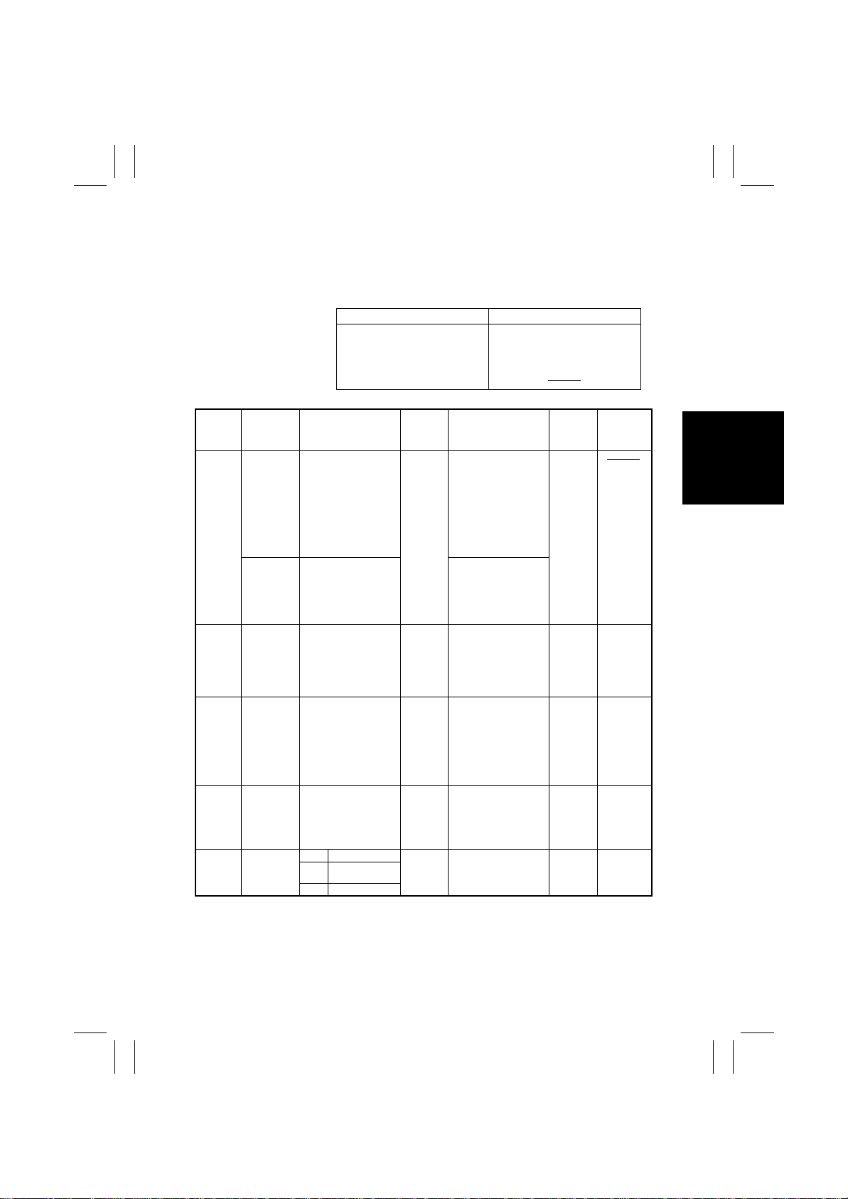
1. SPECIFICATIONS
Type :Multi Staple Finisher with Saddle
Installation :Freestanding
Modes :
Normal Hole Punch (optional)
Non-Sort Non-Sort Hole Punch
Sort Sort Hole Punch
Sort Staple Sort Staple Hole Punch
Saddle Staple
Paper
Mode Paper Type Paper Size
Non-Sort Plain Paper
Recycled
Paper
A6T to A3 Wide
5-1/2 x 8-1/2
8-1/2 x 5-1/2
8-1/2 x 11
11 x 8-1/2
8-1/2 x 14
11 x 17
"
"
"
"
12-1/4 x 18
Post Card
Envelop
OHP Film
Label Paper
Max. Min.
CD311.5mm 86mm
FD457.2mm 139.7mm
Cardboard
Sort Plain Paper A4L, A4C, A3
Sort
Staple
Saddle
Staple
8-1/2 x 11
11 x 8-1/2
8-1/2 x 14
11 x 17
Plain Paper
Cardboard
A4L, A4C, A3
8-1/2 x 11
11 x 8-1/2
8-1/2 x 14
11x17
Plain Paper A4L, A3
8-1/2 x 11
11 x 8-1/2
"
"
"
"
"
"
"
"
"
"
LGL, 11 x 17
Hole
Punch
(optional)
Plain Paper
4 holes A4C, A3L
2 holes 8-1/2 x 11",11 x 8-1/2"
8-1/2 x 14", 11 x 17"
3 holes 8-1/2 x 11'', 11 x 17''
"
"
"
"
Weight
(g/m2)
64 to 256
g/m2
64 to 90
g/m2
Normal Mode
64 to 90
g/m2
64 to 90
g/m2
64 to 209
g/m2
Tray Capacity Exit Tray
64 to 90g/m2 Elevator
A4L / LTR
No. of
or smaller
Sheets
1000
Height
150mm
Controlled by whichever
reached earlier
20 sheets
A4L / LTR
or smaller
No. of
1000
Sheets
150mm
Height
Controlled by whichever
reached earlier
A4L / LTR
No. of
or smaller
Sheets
Height
150mm
No. of
Sets
Controlled by which-
ever reached earlier
10 sets
(No. of Sheets to be Stapled: 6 to 10)pages
20 sets
(No. of Sheets to be Stapled: 2 to 5)pages
(Booklet)
1000
30
LGL or
larger
500
75mm
LGL or
larger
500
75mm
LGL or
larger
500
75mm
30
Tray
Elevator
Tray
Elevator
Tray
Booklet
Tray
Elevator
Tray
No. of
Sheets to
be Stapled
Normal Mode *1
LGL
A4L / LTR
or smaller or
larger
2 to 50 2 to 25
2 to 10
sheets
(Max. 40
pages)
*1: The number of Sheets to be Stapled is limited for hi gh-density images. (Color Wise: 3 t o
20 sheets)
G-1
Page 10

FrameMaker Ver.5.5E(PC) FS-231 OPTION For 8020/8031
02.08.23
Registration
No. of Holes (optional)
Stapling
Staple Filling Mode
Staple Detection
Stapling Position
Stapled Paper Size
Manual Staple
Folding Mode
Folding Position
Power Requirement
Power Consumption
Dimensions
Weight
Environmental Requirements
Supplies
:
Center
:
Metric: 4holes, Inch: 2holes / 3holes
:
Dedicated Staple Cartridge Mode (5000 staples)
:
Available (Nearly Empty: 40 remaining staples)
:
Rear: Parallel 1 point
:
Front: Parallel 1 point
:
Center: Parallel 2 points
:
A4L, A4C, A3, 8-1/2 x 11", 11 x 8-1/2", 8-1/2 x 14", 11 x 17"
:
None
:
Roller Pressure Folding
:
Center of Paper
:
DC24V (supplied from the copier)
:
DC5V (generated within the FS)
:
65W or less
:
601mm (W)x933mm (H)x603mm (D)
:
41.6kg
:
Same as the copier
:
Staple Cartridge
G-2
Page 11
FrameMaker Ver.5.5E(PC) FS-231 OPTION For 8020/8031
02.08.23
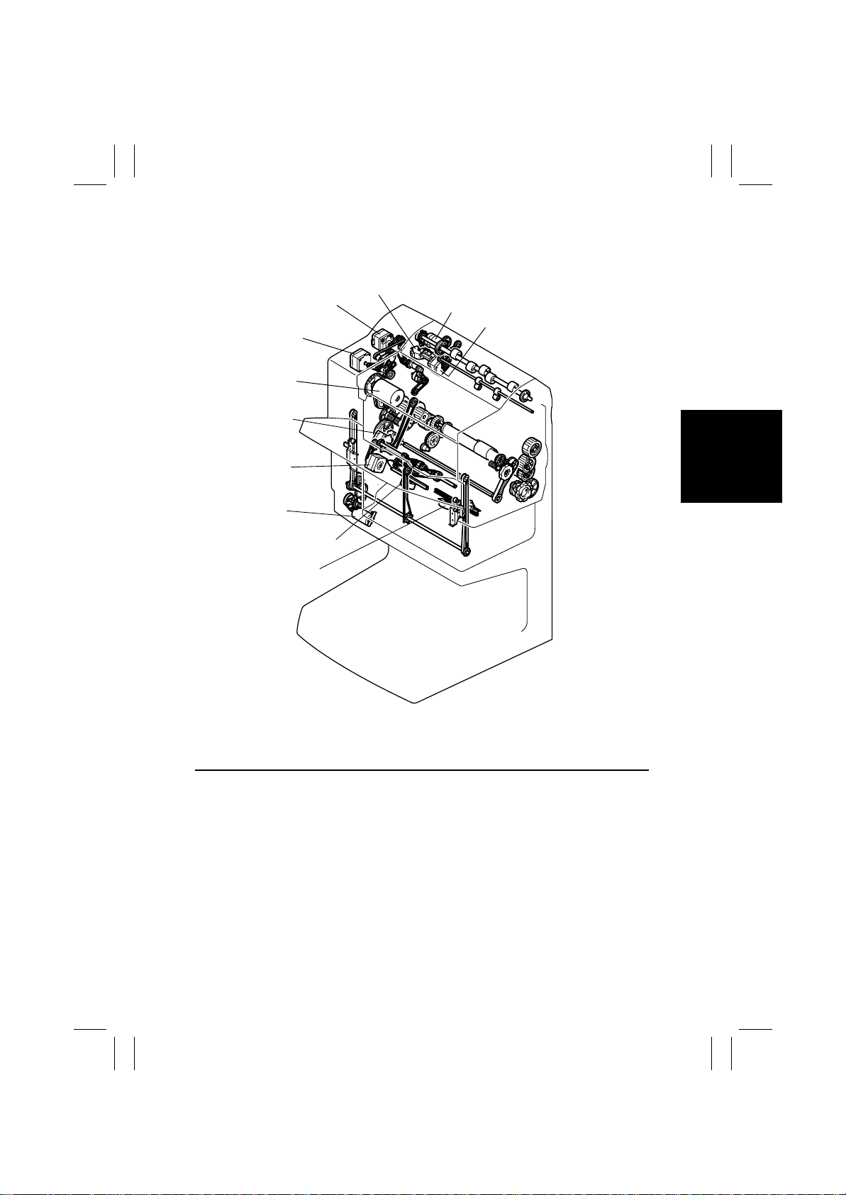
2. ELECTRICAL COMPONENT LAYOUT
M2P
M1
M2
M7
M8
M3
M6
M5
M1P
M9
M4
Symbol Name
M1 Transp ort Motor
M2 Paddle Motor
M3 Exit Motor
M4 Front Aligning Motor
M5 Rear Aligning Motor
M6 Shift Motor
M7 Staple / Folding Motor
M8 Slide Motor
M9 Entrance Motor
4583-301-03
G-3
Page 12
FrameMaker Ver.5.5E(PC) FS-231 OPTION For 8020/8031
02.08.23
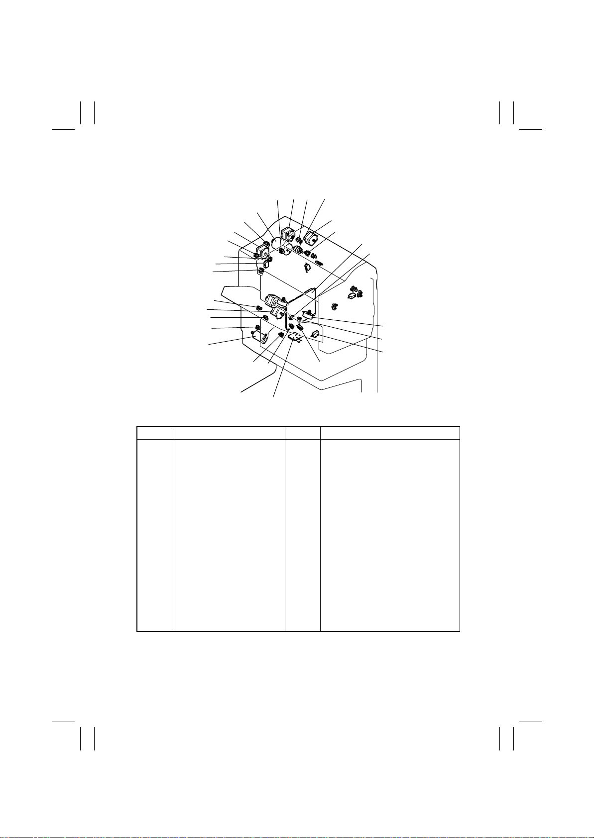
3. DRIVE SYSTEM
M7
PI14
M2
PI15
PI2
MS3
PI5
PI16
M8
PI24
PI17
M6
PI13
M3
PI9
MS2
M5
PI8
CL1PI1M1PI3
PI11
PI10
PI4
M9
PI12
MS1
PCB-CONT
PI7
PI23
PI22
M4
PI6
MS4
4583-301-03
PI18
Symbol Name Symbol Name
PCBCONT
M1
M2
M3
M4
M5
M6
M7
M8
M9
SL1
PI1
PI2
PI3
PI4
PI5
PI6
Finisher Control Boar d
Transport Motor
Paddle Motor
Exit Motor
Front Aligning Motor
Rear Aligning Motor
Shift Motor
Staple / Folding Motor
Slide Motor
Entrance Motor
Entrance Switching Solenoid
Entrance Sensor
Paddle Home Position Sensor
Swing Guide Home Position
Sensor
Front Aligning Plate Home Position Sensor
Rear Aligning Plate Home Position Sensor
Finisher Tray Sensor
PI7
PI8
PI9
PI10
PI11
PI12
PI13
PI14
PI15
PI16
PI17
PI18
PI22
PI23
PI24
MS1
MS2
MS3
MS4
Exit Belt Home Position Sensor
Exit Tray Sensor
Exit Home Position Sensor
Folding Position Sensor
Folding Home Position Sensor
Folding Roller Home Position Sensor
Saddle Tray Sensor
Staple / Folding Motor Clock Sensor
Shift Upper Limit Sensor
Shift Lower Limit Sensor
Shift Motor Clock Sensor
Slide Home Position Sensor
Front Door Open Sensor
Upper Cover Open Sensor
Stack Full Sensor
Front Door Open Sensor
Joint Open Sensor
Staple Safety Sensor (Rear)
Staple Safety Sensor (Front)
G-4
Page 13

FrameMaker Ver.5.5E(PC) FS-231 OPTION For 8020/8031
02.08.23
SWITCHES ON PCB
Page 14

FrameMaker Ver.5.5E(PC) FS-231 OPTION For 8020/8031
02.08.23
Blank page
Page 15
FrameMaker Ver.5.5E(PC) FS-231 OPTION For 8020/8031
02.08.23
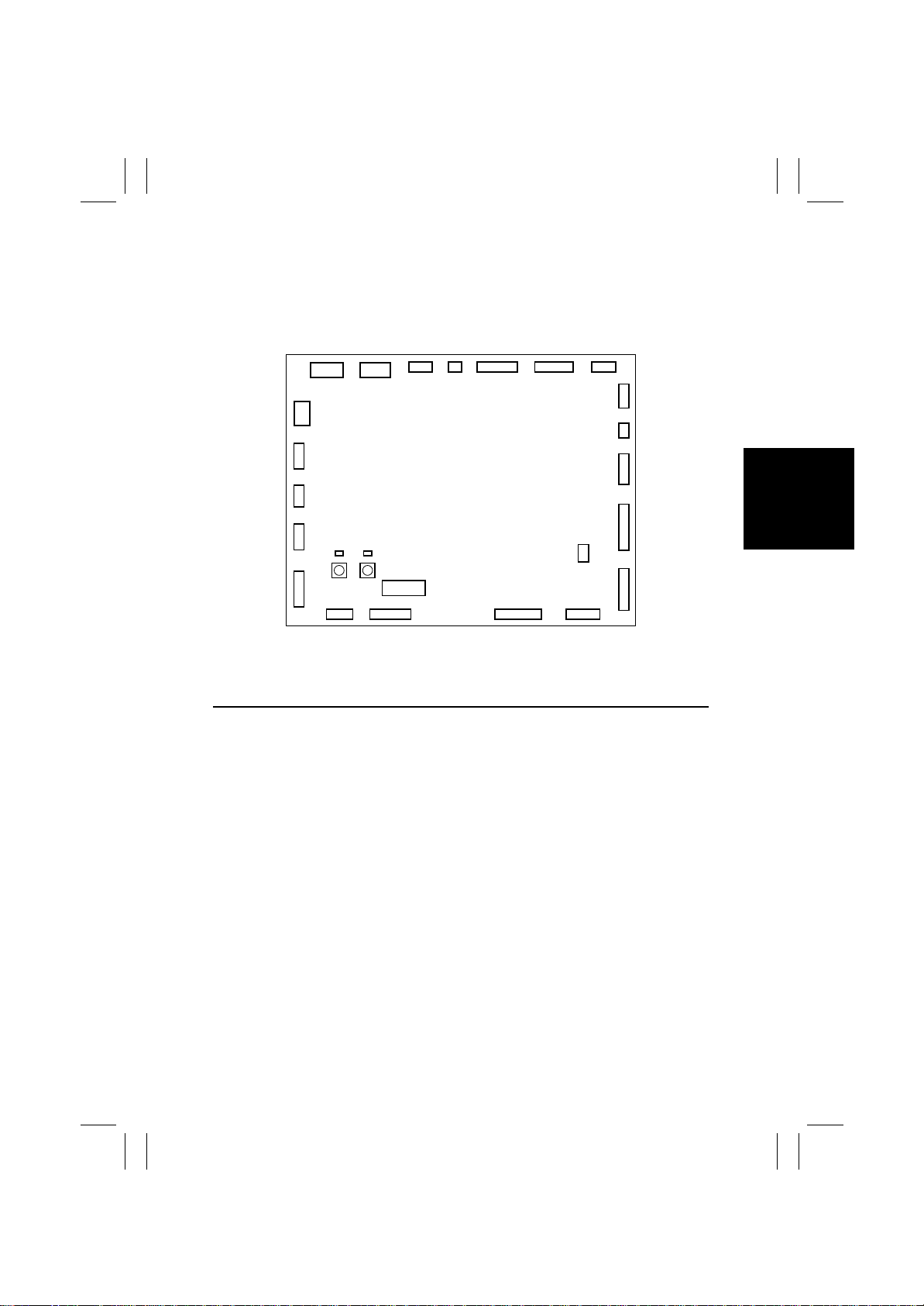
1. CONTROL BOARD
1-1. Finisher Control Board
6
1
41
3
CN1
1
5114151 12
LED2
LED1
CN16CN12CN17CN14
PSW2
PSW1
CN2 CN21 CN9 CN11
5111 112 1 6
CN6CN8
SW1
119711114
4583-301-03
CN10CN18CN22
102
CN19
17319 1 1 11215
CN13CN3
CN7 CN20 CN5
CN4
CN15
Switch Function
SW1 Used to adjust the folding position and adjust the center 2-point stapling position.
PSW1 Used to adjust the folding position and adjust the center 2-point stapling position.
PSW2 Used to adjust the folding position and adjust the center 2-point stapling position.
S-1
Page 16
FrameMaker Ver.5.5E(PC) FS-231 OPTION For 8020/8031
02.08.23
1-2. SW1/PSW1/PSW2
By using SW1, PSW1 and PSW2 on the Control Board, basic adjustment for the folding
positions and the stapling positions can be made independently from the Finisher.
(1) Adjustment of the Folding Positions
When a folding position is adjusted, adjust the folding position to the stapling position.
Make this adjustment after replacing the Finisher Control Board or when the folding position must be changed for some reason.
NOTES
Depending on the type of paper, both the folding position and the stapling position may be
inaccurate. In this case, make adjustment independently from the Finisher. In this independent adjustment from the Finisher, set the adjustment value of "Center Stapling Position"
and "Folding Position" in the service mode to +/- 0mm on the copier.
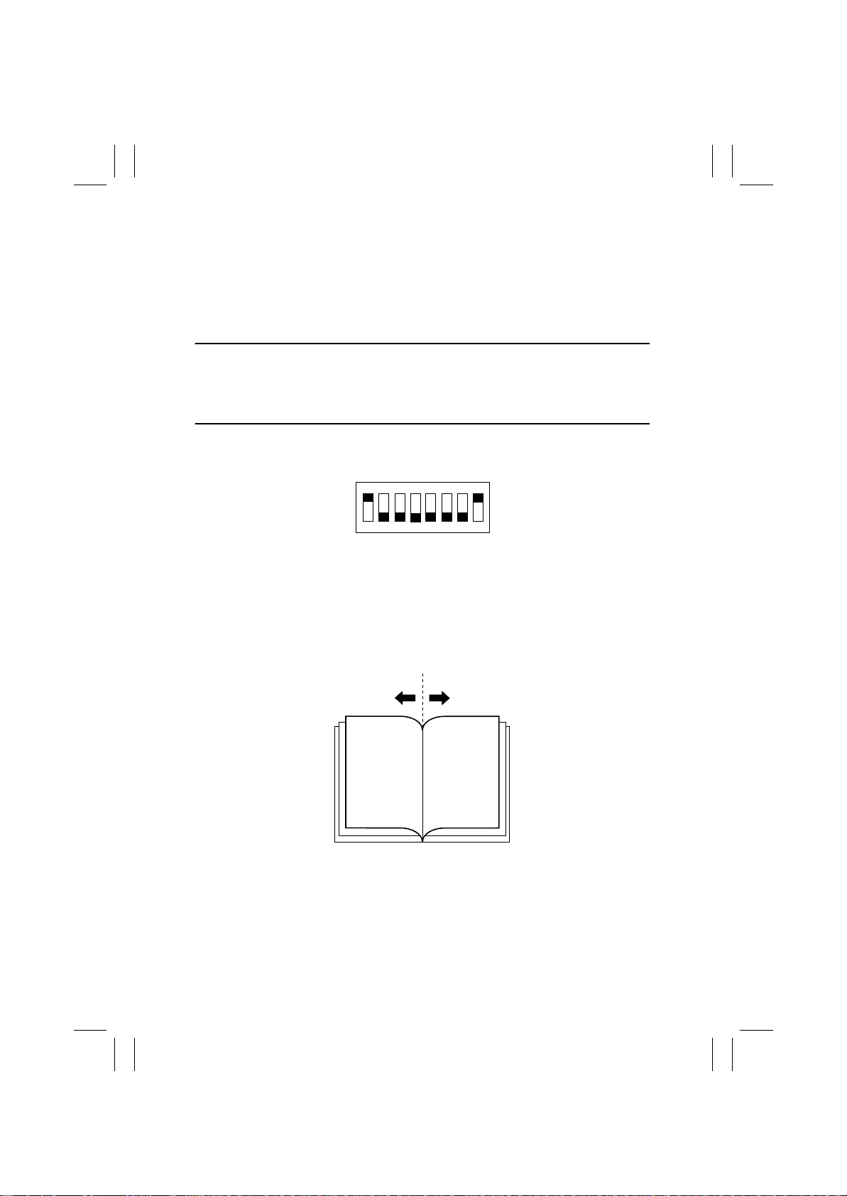
1. Set SW1 on the Finisher Control Board as shown below:
ON
12345678
4583-101-16
2. Press PSW1 or PSW2 on the Finisher Control Board for the required times to adjust the
folding position. One pressing of the switch moves the folding position by approx.
0.16mm.
• Press PSW1 to move the folding position in the "-" direction.
• Press PSW2 to move the folding position in the "+" direction.
• Press PSW1 and PSW2 simultaneously to clear the present set adjustment value.
"-" direction
4583-101-26
"+" direction
3. After setting the adjustment value of the folding position, set all bits of SW1 on the Finisher Control Board to OFF.
4. Perform the "Booklet Creation" on the copier, and confirm that the folding position has
been correctly adjusted. If not, redo the adjustment.
S-2
Page 17
FrameMaker Ver.5.5E(PC) FS-231 OPTION For 8020/8031
02.08.23
(2) Adjustment of the Center Stapling Position
When a stapling position is adjusted, adjust the stapling position to the folding position.
Make this adjustment after replacing the Finisher Control Board or when the stapling position must be changed for some reason.
NOTES
Depending on the type of paper, both the folding position and the stapling position may be
inaccurate. In this case, make adjustment independently from the Finisher. In this independent adjustment from the Finisher, set the adjustment value of "Center Stapling Position"
and "Folding Position" in the service mode to +/- 0mm on the copier.
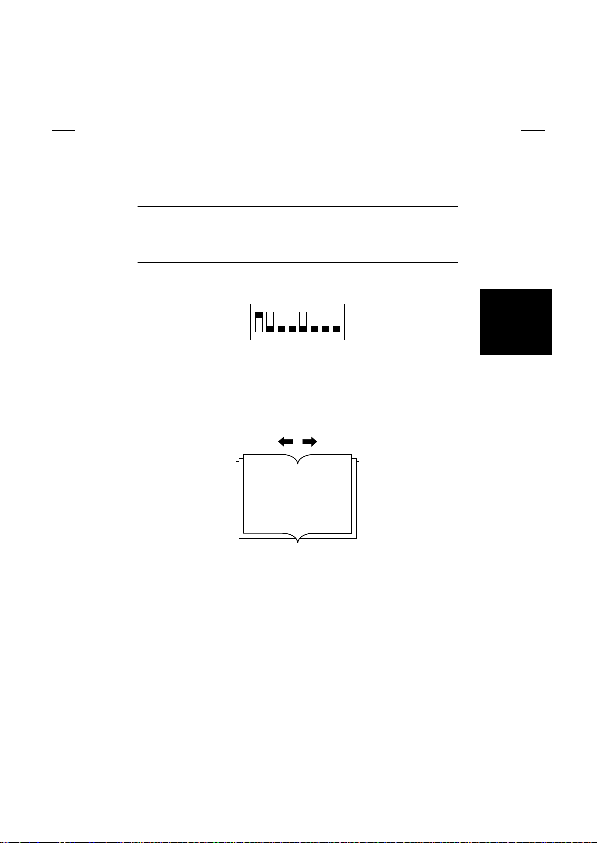
1. Set SW1 on the Finisher Control Board as shown below:
ON
12345678
4583-101-18
2. Press PSW1 or PSW2 on the Finisher Control Board for the required times to adjust the
stapling position. One pressing of the switch moves the stapling position by approx.
0.14mm.
• Press PSW1 to move the stapling position in the "-" direction.
• Press PSW2 to move the stapling position in the "+" direction.
• Press PSW1 and PSW2 simultaneously to clear the present set adjustment value.
"-" direction
4583-101-26
"+" direction
3. After setting the adjustment value of the stapling position, set al l bits of SW1 on the Finisher Control Board to OFF.
4. Perform the "Booklet Creation" on the copier, and confirm that the stapling position has
been correctly adjusted. If not, redo the adjustment.
S-3
Page 18
FrameMaker Ver.5.5E(PC) FS-231 OPTION For 8020/8031
02.08.23
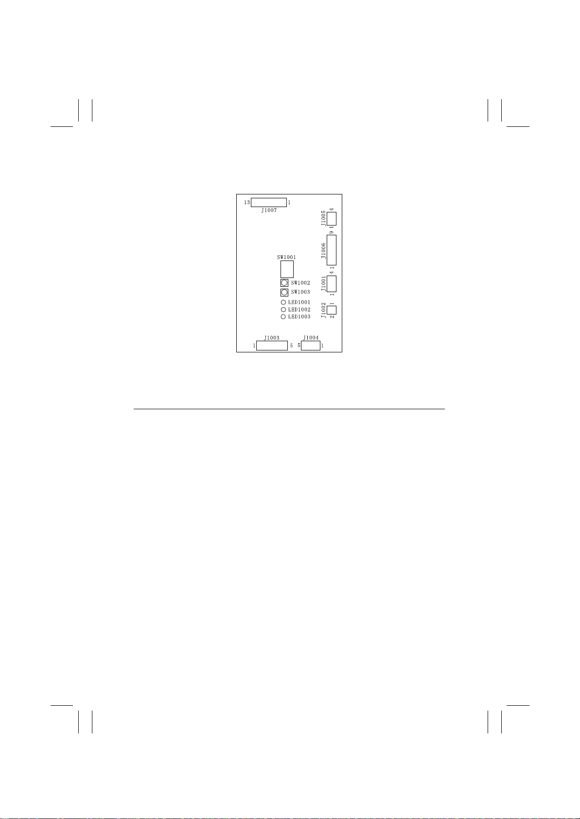
1-3. Punch Control Board
4583-602-01
Switch Function
SW1001 Used to register the number of punched holes and adjust the sensor output.
SW1002 Used to register the number of punched holes and adjust the sensor output.
SW1003 Used to register the number of punched holes and adjust the sensor output.
S-4
Page 19
FrameMaker Ver.5.5E(PC) FS-231 OPTION For 8020/8031
02.08.23
(1) Adjustment of the Sensor Outp ut
Be sure to make this adjustment after replacing the Punch Control Board, the Side Registration Sensor (Photosensor Board or LED Board) or the Punch Dust Full Sensor (Punch
Dust Full Sensor Board or Punch Dust Full LED Board).
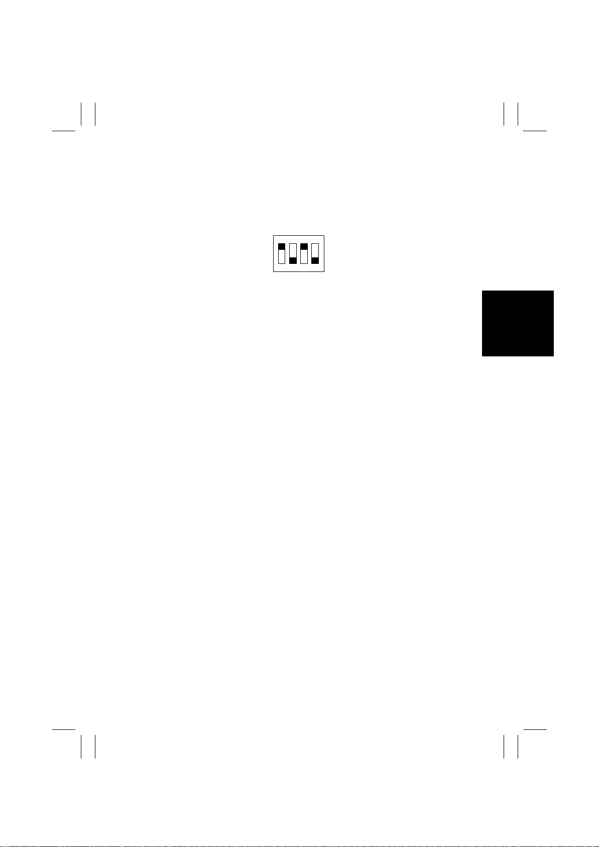
1. Set the bits 1 through 4 of DIPSW1001 on the Punch Control Board as shown below:
ON
1234
4583-102-57
2. Press SW1002 or SW1003 on the Punch Control Board. The sensor output will be automatically adjusted.
• When all LED1001, LED1002 and LED1003 light up, the adjustment has been com-
pleted.
3. Set all bits of DIPSW1001 to OFF.
S-5
Page 20

FrameMaker Ver.5.5E(PC) FS-231 OPTION For 8020/8031
02.08.23
(2) Registration of the Number of Punch Holes
In order for the Finisher to recognize the number of punch holes that can be achieved by
the installed Punch Unit, such number of punch holes is registered in the IC on the Punch
Control Board. Make this registration whenever the Punch Control Board has been
replaced.
• However, this registration is not necessary if the EEP-ROM used on an old board has
been reinstalled to a new board.
1. Set the bits 1 through 4 of DIPSW1001 on the Punch Control Board as shown below:
ON
1234
4583-102-58
2. Press SW1002 on the Punch Control Board to select the number of punch holes.
• Each time SW1002 is pressed, the following display changes in the descending order
shown below:
Number of Punch Holes
2 (Punch Unit J1) ON OFF OFF
2/3 (Punch Unit K1) ON ON OFF
4 (Punch Unit G1) OFF ON OFF
4 (Punch Unit H1) OFF OFF ON
LED
1001
LED
1002
LED
1003
3. Press SW1003 on the Punch Control Board twice. The number of punch holes will be
registered in the Punch Control Board.
• The pressing of SW1003 changes the steady lighting of the LED to flickering, and the
pressing of SW1003 again changes the flickering of the LED to steady lighting. This completes the registration.
4. Set all bits of DIPSW1001 to OFF.
S-6
Page 21

FrameMaker Ver.5.5E(PC) FS-231 OPTION For 8020/8031
02.08.23
(3) Procedure after Replacing the EEP-ROM (IC1002)
1. Turn OFF the POWER switch of the copier.
2. Set the bits 1 through 4 of DIPSW1001 on the Punch Control Board as shown below:
ON
1234
4583-102-59
3. Press SW1002 and SW1003 on the Punch Control Board simultaneously.
• This will initialize the EEP-ROM. After the initialization, all LED1001, LED1002 and
LED1003 light up.
4. Adjust the sensor output, and register the number of punch holes.
5. Set all bits of DIP SW 1001 to OFF.
S-7
Page 22

FrameMaker Ver.5.5E(PC) FS-231 OPTION For 8020/8031
02.08.23
Blank page
S-8
Page 23

FrameMaker Ver.5.5E(PC) FS-231 OPTION For 8020/8031
02.08.23
DIS/REASSEMBLY,
ADJUSTMENT
Page 24

FrameMaker Ver.5.5E(PC) FS-231 OPTION For 8020/8031
02.08.23
Blank page
Page 25

FrameMaker Ver.5.5E(PC) FS-231 OPTION For 8020/8031
02.08.23
1. LIST OF COMPONENTS TO BE PERIODICALLY
CHECKED
• In order for you to always take satisfactory copies from your copier and also to hold your
copier steady for a long time, periodic maintenance is required for the following components:
Component to be Peri-
odically Checked
Roller and Roll at
Paper Transport Sec-
tion
Transport Path:
Guide Plate
Sensor 300 Brush, Blower Brush Detection Error
Cleaning
(K)
300 Alcohol or Water Transport Error
300 Brush, Blower Brush Transp ort Error
Cleaning Means Possible Trouble
D-1
Page 26
FrameMaker Ver.5.5E(PC) FS-231 OPTION For 8020/8031
02.08.23
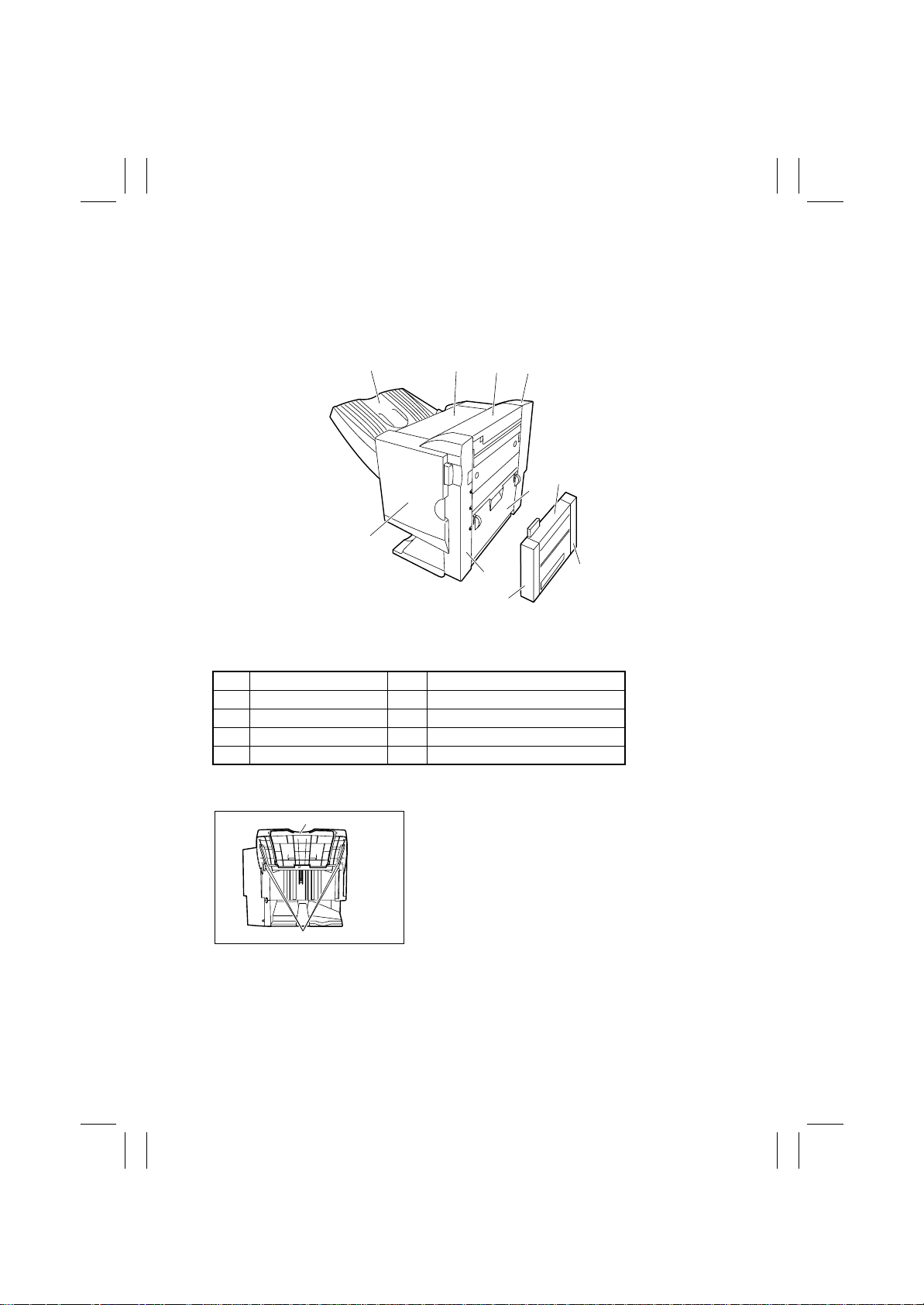
2. STAPLING UNIT (DRIVE SECTION)
2-1. Removal of the External Covers and Components
[1] [2]
[5] [6]
[4]
[3]
[8]
4583-101-01
[1] Exit Tray (4) [2] Rear Cover (3)
[3] Front Cover (4) [4] Front Door
[5] Upper Door [6] Upper Cover (4)
[7] Jam Access Cover [8] Middle Font Cover (2)
[9] Middle Upper Cover [10] Middle Rear Cover (2)
The figure in ( ) indicates the number of fixing screws.
(1) Removal of the Exit Tray
[2]
1. Remove the four screws [1], and remove the Exit
Tray [2].
[9]
[7]
[10]
[1]
4583-101-02
D-2
Page 27
FrameMaker Ver.5.5E(PC) FS-231 OPTION For 8020/8031
02.08.23
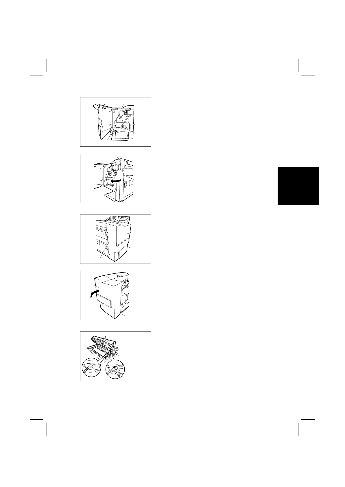
(2) Removal of the Front Cover
[1] [4]
[3]
[2]
[4]
4583-101-03
[6]
[5]
4583-101-04
(3) Removal of the Rear Cover
[3]
[2]
[1]
4583-101-05
1. Remove the Horizontal Transpor t Unit.
2. Remove the Middle Transport Unit.
3. Open the Font Door [1].
4. While pinching the claws [2], remove the Folding
Jam Release Dial [3].
5. Remove the two screws [4].
6. Remove the one screw [5], and remove t he Front
Cover [6].
1. Remove the Horizontal Transpor t Unit.
2. Remove the Middle Transport Unit.
3. Remove the one screw [1] at the Paper Take-Up
Section and the one screw [2] at the Paper Exit
Section, and remove the Rear Cover [3].
[3]
[2]
4583-101-06
(4) Removal of the Upper Door
[1]
Ground Wire
[4]
[3]
[2]
4583-101-31
1. Open the Upper Door [1], remove the Door Band
Holder [2] by turning it clockwise.
2. Remove the Door Band [3]. Remove the screw
[4], and remove the grounding wire.
D-3
Page 28
FrameMaker Ver.5.5E(PC) FS-231 OPTION For 8020/8031
02.08.23
[6]
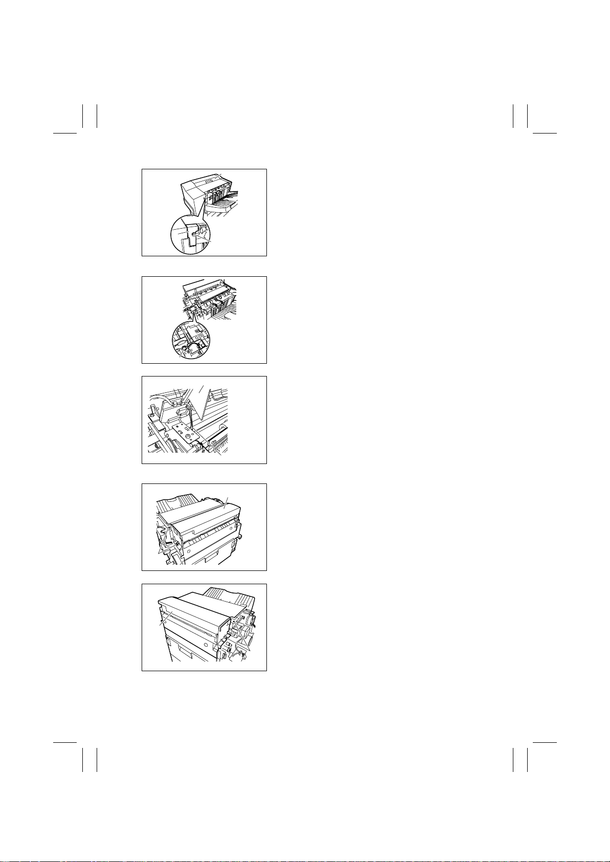
3. Remove the screw [4], remove the Finisher Tray
Rear Cover [5], and remove the Upper Door [6].
[5]
[4]
4583-101-08
(5) Removal of the Finisher Tray Upper Door
1. Remove the Horizontal Transpor t Unit.
2. Remove the Middle Transport Unit.
3. Remove the Front Cover. (Refer to 2-1. (2).)
4. Remove the Rear Cover. (Refer to 2-1. (3).)
5. Remove the Upper Door. (Refer to 2-1. (4).)
6. Unplug the connector [1].
[1]
[3]
4583-101-09
7. Unplug the connector [4] while holding up the
Finisher Tray Upper Door [3], and remove the
Finisher Tray Upper Door [3].
[4]
4583-101-10
(6) Removal of the Upper Cover
[3]
[1]
4583-101-11
[3]
[2]
4583-101-12
Remove the Middle Transport Unit.
1. Remove the Horizontal Transpor t Unit.
2. Remove the Middle Transport Unit.
3. Remove the Front Cover. (Refer to 2-1. (2).)
4. Remove the Rear Cover. (Refer to 2-1. (3).)
5. Remove the two fr ont screws [1] and the two rear
screws [2], and remove the Upper Cover [3].
D-4
Page 29
FrameMaker Ver.5.5E(PC) FS-231 OPTION For 8020/8031
02.08.23
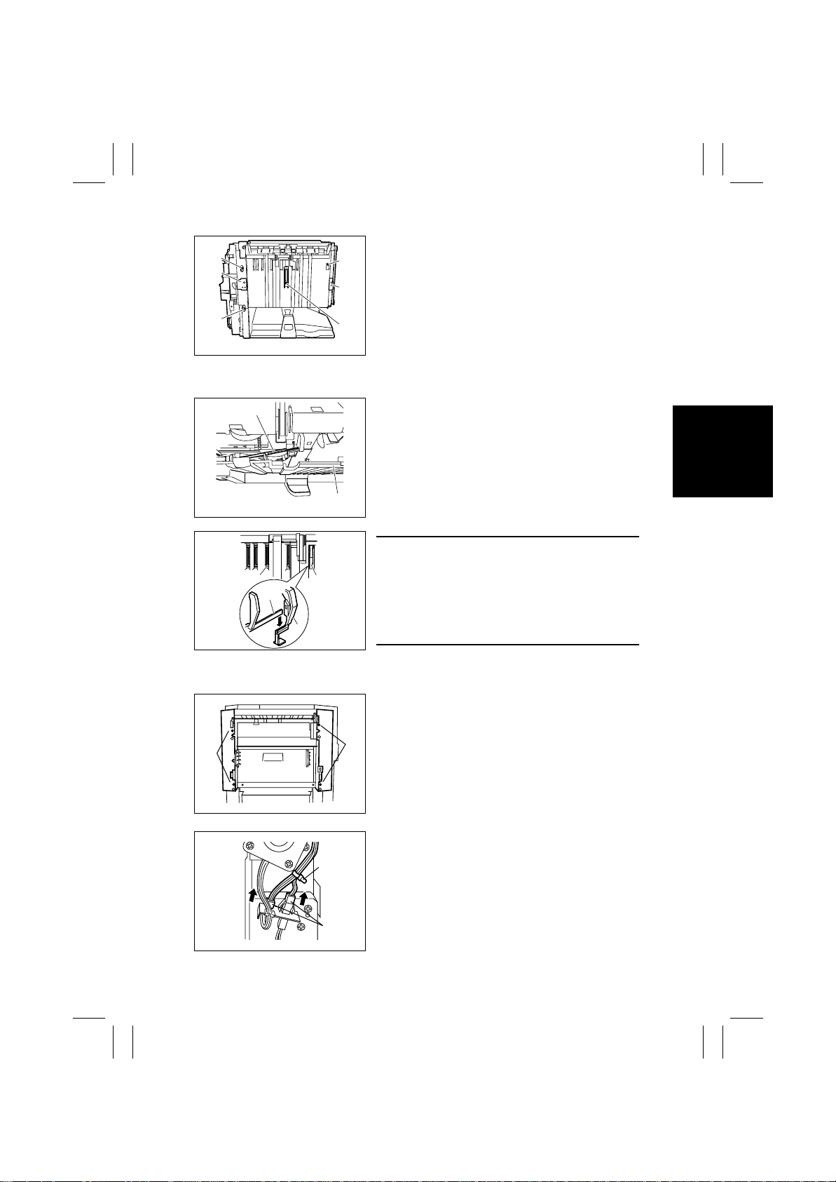
(7) Removal of the Side Guide
[3]
[2]
[3]
[5]
[5]
[5]
[6]
4583-101-13
[4]
4583-101-14
[6]
4583-101-15
[3]
[1]
[3]
1. Remove the Horizontal Transpor t Unit.
2. Remove the Middle Transport Unit
3. Remove the Exit Tray. (Refer to 2-1 (1).)
4. Remove the Front Cover. (Refer to 2-1. (2).)
5. Remove the Rear Cover. (Refer to 2-1. (3).)
6. Derail the Exit Tray Support Plate (Front) [1] and
the Exit Tray Support Plate (Rear) to the outside
off the respective rail grooves.
7. Remove the four screws [3].
8. Pull down the Side Guide [4] lightly, disengage
the Exit Tray Home Position Detecting Lever
(Rear) [5], and then remove the Side Guide [4].
NOTE
In reassembling, ensure of exact installation with the
Exit Tray Home Position Detecting Lever (Rear) [5]
set in the slot of the Exit Tray Home Position Detecting Lever (Center) [6].
After reassembly, press each of these levers for several times to make sure of exact installation.
(8) Removal of the Middle Transport Unit
1. Remove the four screws [1]. Hold up the Middle
Front Cover and the Middle Rear Cover, and
remove them while shifting them back and forth.
[1]
[1]
4583-101-20
2. Unplug the two connectors [2]. Pinch the tie band
[3], and remove it from the sheet metal.
[3]
[2]
4583-101-21
D-5
Page 30
FrameMaker Ver.5.5E(PC) FS-231 OPTION For 8020/8031
02.08.23
[5]
[4]
4583-101-22
3. Remove the two screws [4].
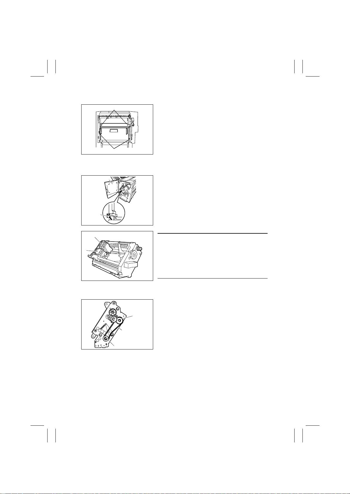
4. Loosen the two screws [5]. Remove the Middle
2-2. Removal of the Sta pler
[1]
[3]
[2]
4583-102-01
[5]
[4]
4583-102-02
1. Open the Front Door [1].
2. Pull out the Stapler [3] while pressing the Stop
NOTE
Do not remove the Stapler from the shaft of the stapler frame, or displacement will be caused between
the position to which the Staple Driver [4] (the lower
unit of the Stapler) feeds staples and the position
from which the Staple Clincher [5] (the upper unit of
the Stapler) receives them.
Transport Unit by sliding it upwards.
Lever [2].
(1) Stapler Phase Adjustment
Gear
Timing Belt
Gear
4583-102-03
Make phase adjustment of the Stapler following the
procedures given below whenever the Gear or Timing Belt in front of the Stapler has been replaced or
removed for some reason, since such replacement or
removal will cause mistiming between the staple driving by the Staple Driver (the lower unit of the Stapler)
and the staple clinching by the Staple Clincher (the
upper unit of the Stapler).
D-6
Page 31
FrameMaker Ver.5.5E(PC) FS-231 OPTION For 8020/8031
02.08.23
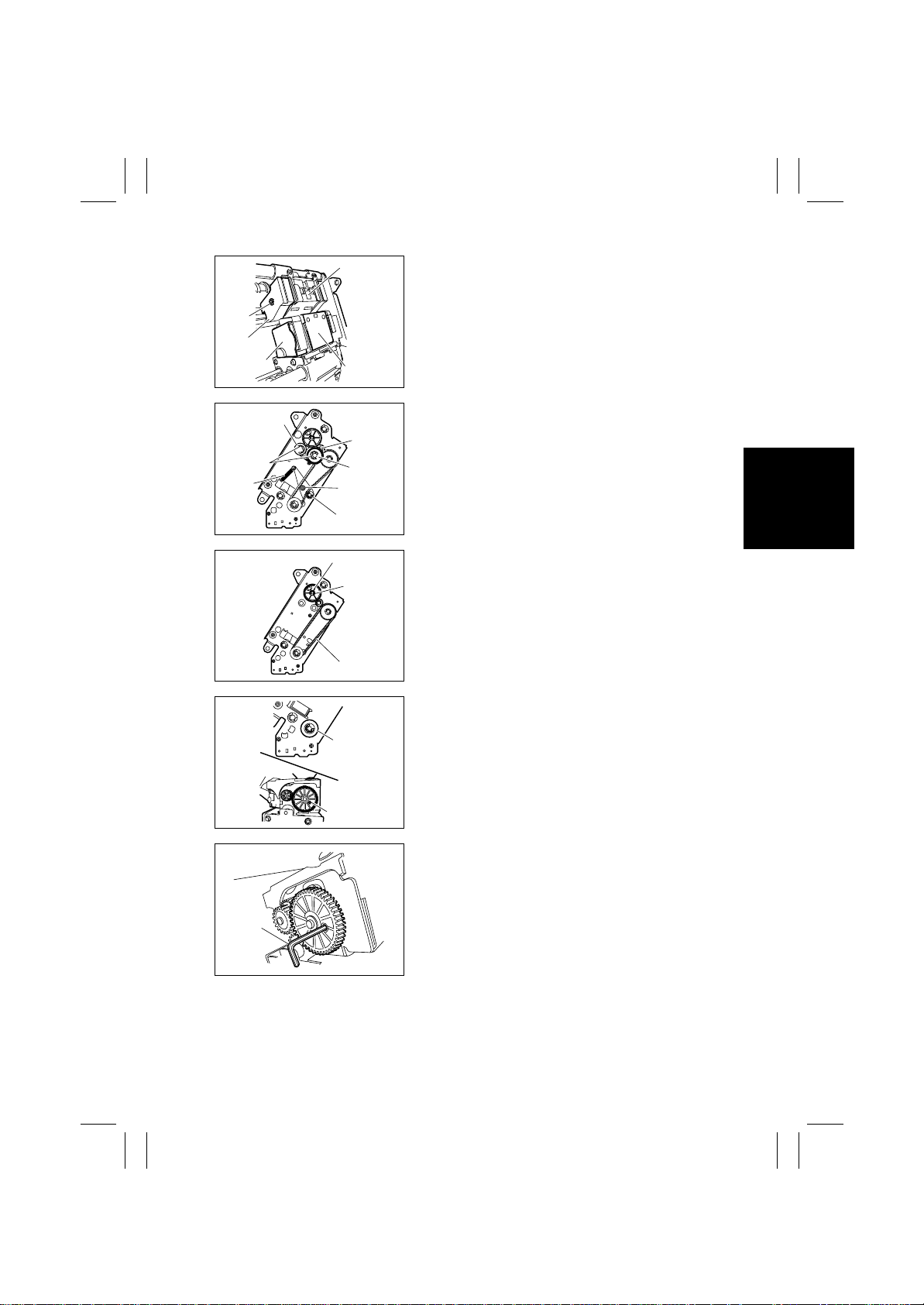
[4]
1. Remove the Gear Cover [2] from the Staple
Driver [1].
2. Remove the E-Ring [3], and remove the Side
[3]
[5]
[2]
[7]
[6]
[11]
[1]
4583-102-04
[8]
[9]
[10]
Cover [5] from the Staple Clincher [4].
3. Remove the two E-Rings [6], and remove the Staple Jam Release Gear [7], the Timing Belt [8] and
the Middle Gear 1 [9]. Also, remove the spacer
and the spring located behind the Staple Jam
Release Gear.
4. Remove the screw [10] and the spring [11], and
remove the Belt Tension Roll [12].
[12]
4583-102-05
[15]
5. Remove the Timing Belt [13].
6. Remove the E-Ring [14], and remove the Staple
[14]
[13]
4583-102-06
Position Confirm Gear [15].
7. Turn the Gear [16] to position the hole [17] in the
Gear of the Staple Driver to the hole behind.
[16]
[18]
[17]
4583-102-07
8. Insert a pin of approx.φ2 [18] (alternatively, 2mm
hexagonal wrench or the like can be preferably
used) into the hole, and fix the Gear.
4583-102-08
D-7
Page 32
FrameMaker Ver.5.5E(PC) FS-231 OPTION For 8020/8031
02.08.23
[19]
[20]
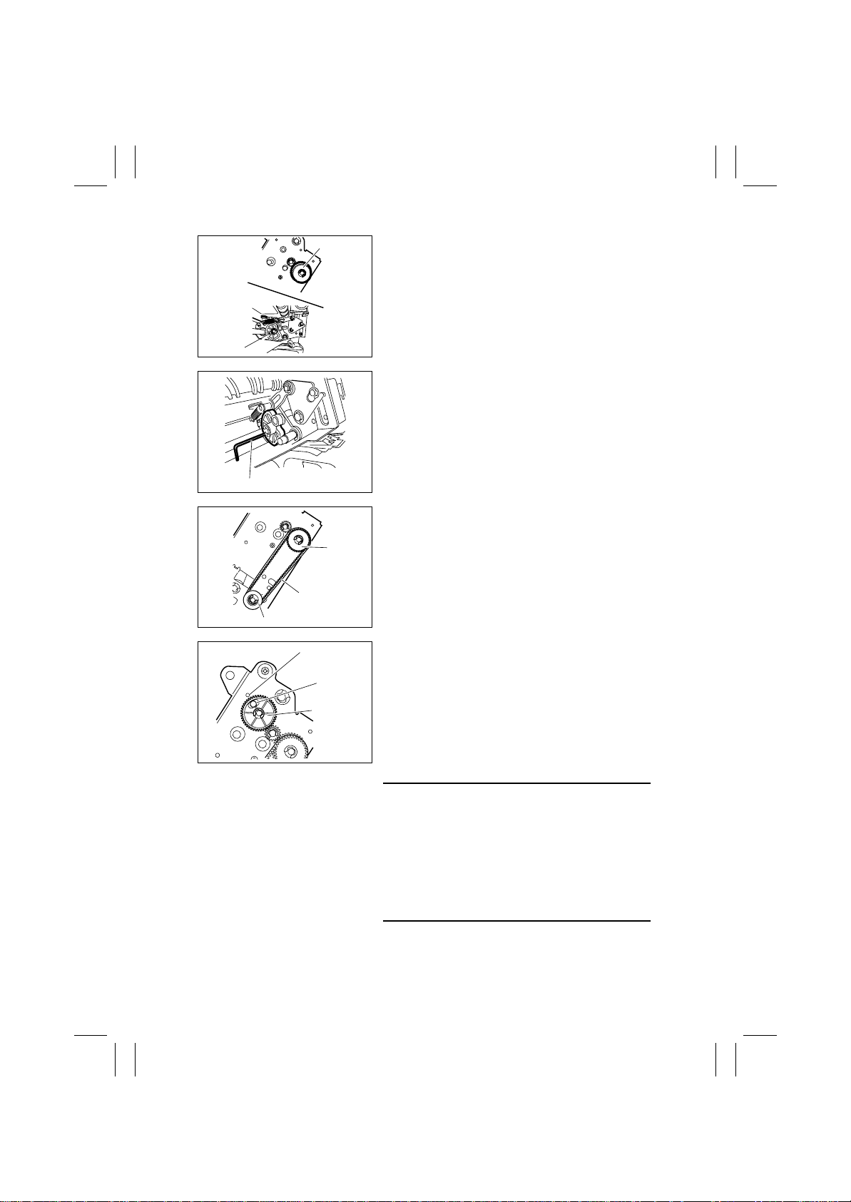
4583-102-09
9. Turn the Gear [19] to position the hole [20] in the
Cam of the Staple Clincher to the hole behind.
10. Insert a pin of approx. φ2 [21] (alternatively, 2mm
hexagonal wrench or the like can be preferably
used) into the hole, and fix the Cam.
[21]
4583-102-10
11. Set the Timing Belt [22] to the Gear [23] and
Gear [24] with the Gear and the Cam in the fixed
[23]
[22]
[24]
4583-102-11
[26]
condition.
12. Install the Staple Position Confirm Gear [27] in
such a way that the blue mark [25] of the Gear
[25]
comes face to face with the hole [26] in the frame.
[27]
4583-102-12
NOTE
The position in which the blue mark meets face to
face with the hole is the home position for stapling. If
the Staple Jam Release Gear is turned for some reason, this home position will shift and the Staple Cartridge will not come off. In this case, the Staple
Position Confirm Gear plays a role of resuming the
stapling home position by referring to the blue mark.
Therefore, the Gear should be set in place correctly.
D-8
Page 33
FrameMaker Ver.5.5E(PC) FS-231 OPTION For 8020/8031
02.08.23
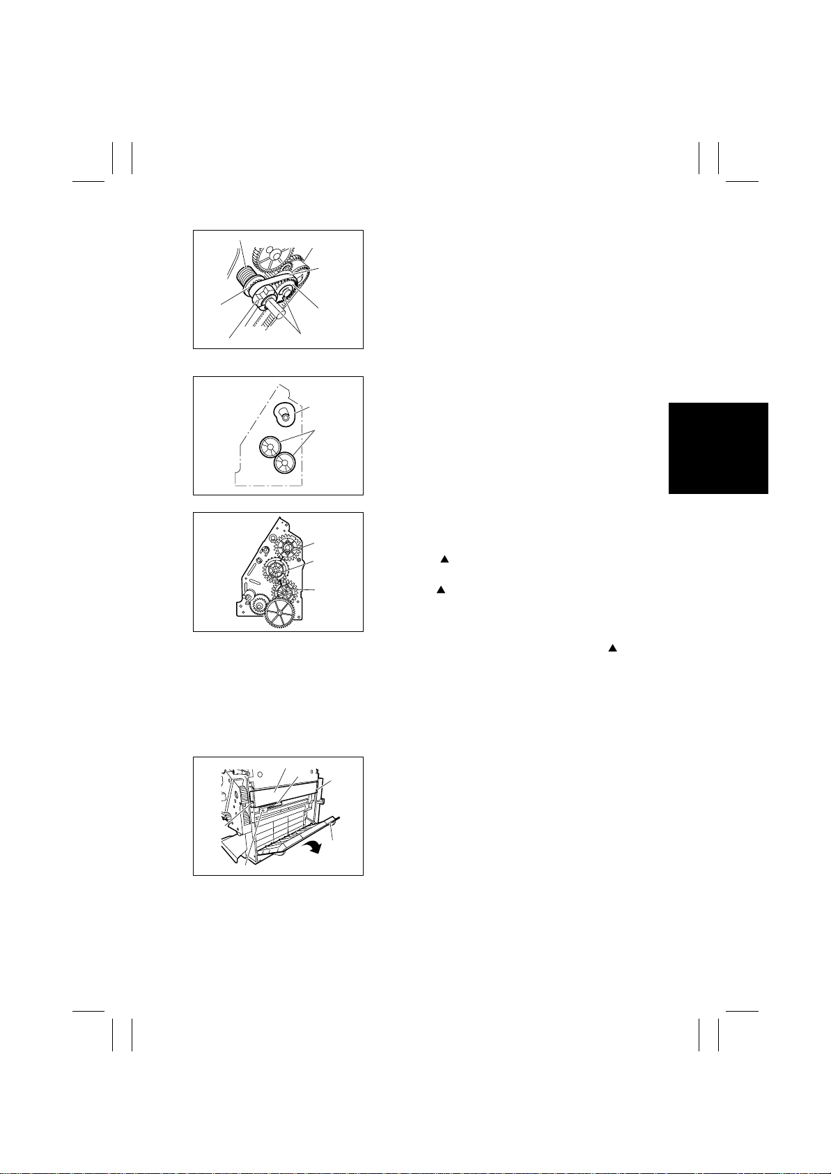
[28]
[31]
[29]
[30]
[33]
[32]
4583-102-13
13. Remove the pin fixing the Gear and the Cam to
14. Set the spring [28], the spacer [29], the Staple
(2) Saddle Gear Phase Adjustment
Whenever the Gear in front of the Saddle or the Fold-
[2]
[1]
4583-102-14
ing Roller has been replaced or removed for some
reason, make gear phase adjustment following the
procedures given below.
1. Set the Folding Roller [1] and Saddle Cam [2]
2. With the Folding Roller and the Saddle Cam posi-
[3]
[4]
[5]
4583-102-15
• The mark on the Saddle Cam Drive Gear [3]
3. With the Saddle Cam Drive Gear [3] and the Mid-
release them.
Jam Release Gear [30], the Timing Belt [31] and
the Middle Gear 1 [32], and fix them with the ERings [33].
within the Saddle as shown in the figure.
tioned as shown in Fig. 4583-102-14, set the
gears as shown in the figure in the following way:
(either of the two marks) comes face to face with
the mark on the Middle Gear [4] (the mark on
the semispherical part with narrow gear face
width).
dle Gear [4] positioned as above, the mark on
the Middle Gear [4] (the mark on the other semispherical part) meets face to face with the rib of
the Folding Roller Drive Gear [5].
2-3. Removal of the Saddle
[3]
[12]
[2]
[1]
[11]
4583-102-16
1. Remove the Horizontal Transpor t Unit.
2. Remove the Middle Transport Unit.
[2]
3. Remove the Front Cover. (Refer to 2-1. (2).)
4. Remove the Rear Cover (Refer to 2-1. (3).)
5. Open the Jam Access Cover [1], remove the two
6. Remove the two screws [11], and remove the
screws [2], and remove the Right Stay [3].
Lever [12].
D-9
Page 34
FrameMaker Ver.5.5E(PC) FS-231 OPTION For 8020/8031
02.08.23
[5]
[4]
4583-102-17
[6]
[7]
[8]
[10] [9]
4583-102-18
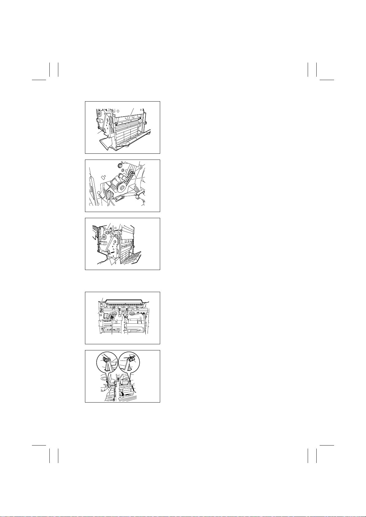
7. Turn the Folding Jam Release Dial [4] to move
the Paper Pressure [5] inside.
8. Remove the Stopper Ring [6], and remove the
Timing Belt [7].
9. Unplug the two connectors [8].
10. Remove the three screws [9], and slightly pull out
the Stapler [10].
11. Pull out and remove the Saddle [11].
[9] [11]
4583-102-19
2-4. Removal of the Finisher Tray
[1]
[2]
[2] [2]
[6]
[4]
1. Remove the Finisher Tray Upper Door. (Refer to
2-1. (5).)
2. Remove the Side Guide. (Refer to 2-1. (7).)
3. Remove the two screws [1], and unplug the five
connectors [2].
[1]
4583-102-20
4. Pull out the Finisher Stopper Base [3], and disengage the front claw [5] and the rear claw [6] of the
[5]
[4]
[3]
4583-102-21
Finisher Stopper [4].
D-10
Page 35
FrameMaker Ver.5.5E(PC) FS-231 OPTION For 8020/8031
02.08.23
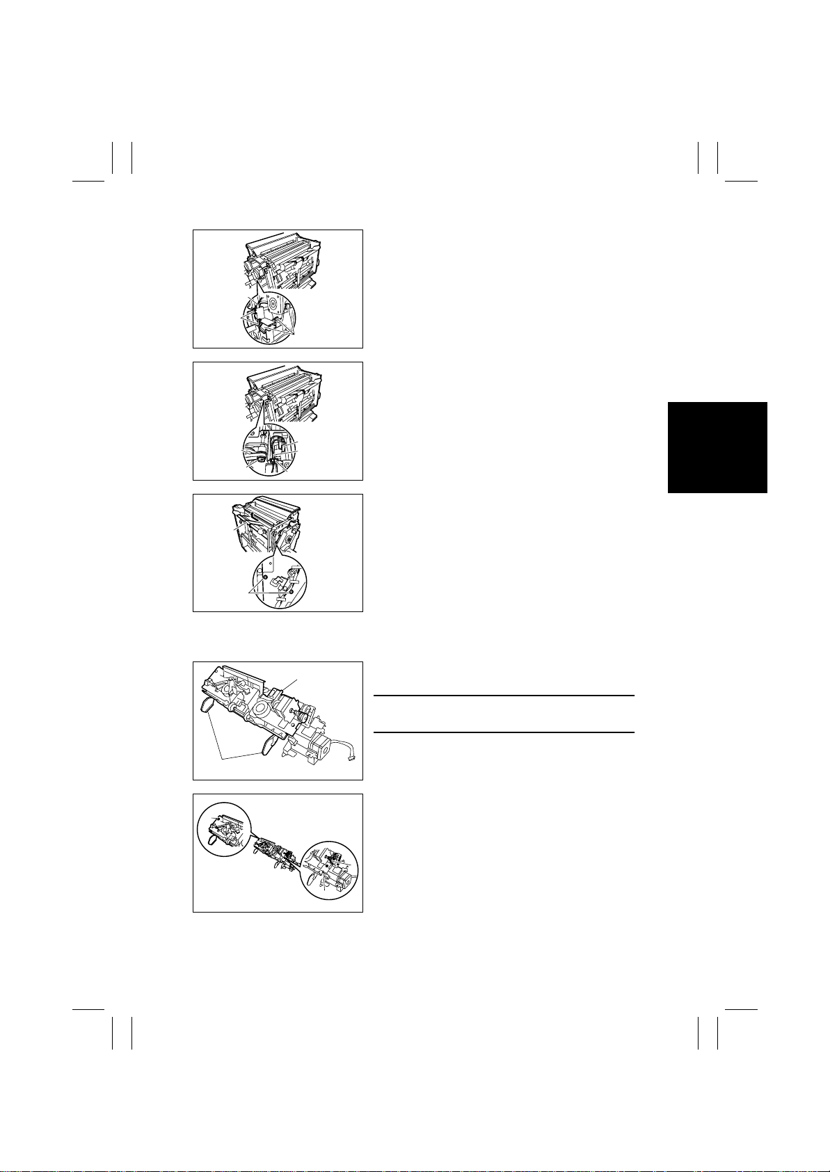
5. Unplug the three connectors [7].
6. Disengage the two claws [8] of the Wire Harness
Clamp, and remove the Motor Wire Harness [9].
[9]
[8]
[7]
4583-102-22
7. Remove the Stopper Ring [10], and remove the
Timing Belt [11].
8. Unplug the connector [12], and remove the Wire
Harness [14] from the Wire Saddle [13].
[11]
[10]
[12]
[14]
4583-102-23
[13]
9. Remove the two screws [15], and remove the
Finisher Tray [16] by sliding it to the far side and
[16]
[15]
4583-102-24
lifting it.
2-5. Removal of the Paddle Section
[1]
[2]
[4]
4583-102-25
1. Remove the Finisher Tray. (Refer to 2-4.)
2. Place the Finisher Tray [1] as shown in the figure.
NOTES
Be careful not to damage the Aligning Plate [2].
3. Remove the Timing Belt [3], and remove the two
screws [4].
[4]
4583-102-26
[3]
D-11
Page 36
FrameMaker Ver.5.5E(PC) FS-231 OPTION For 8020/8031
02.08.23
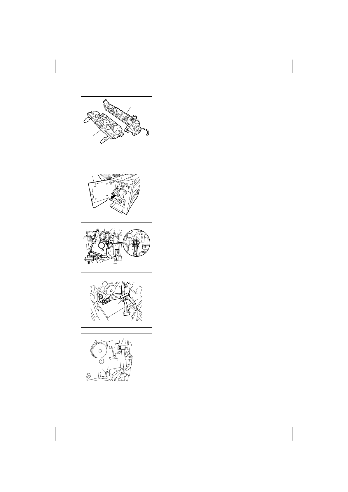
4. Separate the section into the Finisher Tray [5]
[6]
and the Paddle Section [6].
[5]
4583-102-27
2-6. Removal of the Stapler/Folding Drive Unit
1. Open the Front Door [1], and slightly pull out the
stapler section [2].
2. Remove the screw [3], and remove the interface
cable presser [4].
3. 3. Release the six Wire Harness Clamps [5], and
unplug the connector [6].
4. 4. Remove the Wire Harness [7] from the Wire
[8]
Harness Clamp [5].
5. 5. Remove the Wire Harness [7] from the Wire
Saddle [8], and unplug the two connectors [9].
6. 6. Release the Wire Harness Clamp [10], and
unplug the connector [11].
7. 7. Remove the Wire Harness [12] from the Wire
Harness Clamp [10].
8. 8. Remove the Wire Harness [12] from the Wire
Saddle [13], and unplug the two connectors [14].
[13]
[2]
4583-102-28
[9]
[5]
[7]
4583-102-29
[11]
[12]
[10]
[1]
[5]
[6]
[7]
[3]
[7]
[5] [7] [5]
[4]
[14]
[16]
[17]
[15]
4583-102-30
9. Remove the screw [15], and remove the claw of
Wire Harness Guide [17] from the square hole
[16] in the base plate.
4583-102-31
D-12
Page 37
FrameMaker Ver.5.5E(PC) FS-231 OPTION For 8020/8031
02.08.23
[18]
[20]
[18]
[19]
4583-102-32
[21]
[21]
4583-102-33
[21]
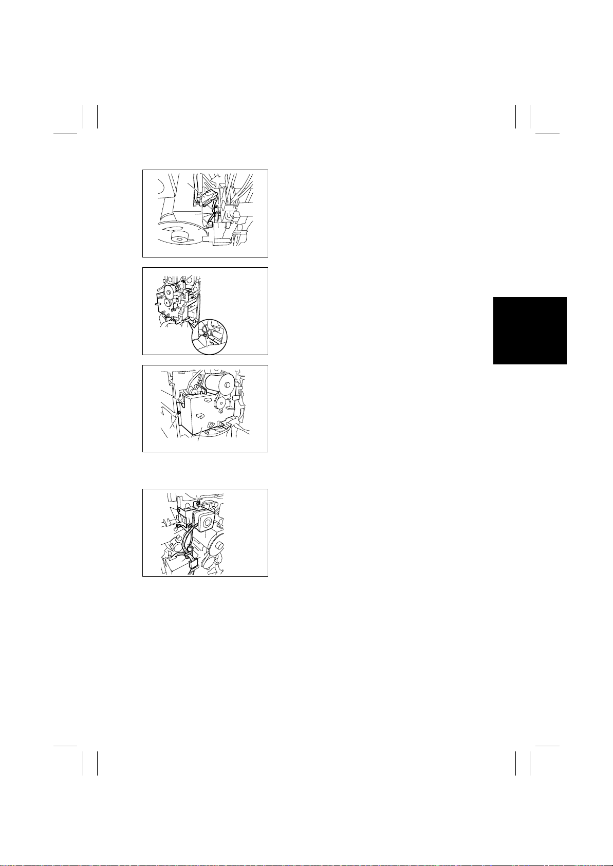
10. Unplug the two connectors [18], and remove the
Wire Harness [20] from the Wire Saddle [19].
11. Remove the three screws [21].
12. Remove the screw [22], and remove the Stapler/
Folding Drive Unit [23].
[22]
[23]
4583-102-34
2-7. Removal of the Transport Motor Unit
[5]
[5]
[3]
1. Remove the Horizontal Transpor t Unit.
2. Remove the Middle Transport Unit.
3. Remove the Rear Cover. (Refer to 2-1. (3).)
4. Open the Wire Harness Clamp [1], and unplug
[4]
[6]
[2]
[1]
4583-102-35
the two connectors [2].
5. Remove the screw [3], and remove the Wire Harness Guide [4].
6. Remove the three screws [5], and remove the
Transport Motor Unit [6].
D-13
Page 38
FrameMaker Ver.5.5E(PC) FS-231 OPTION For 8020/8031
02.08.23
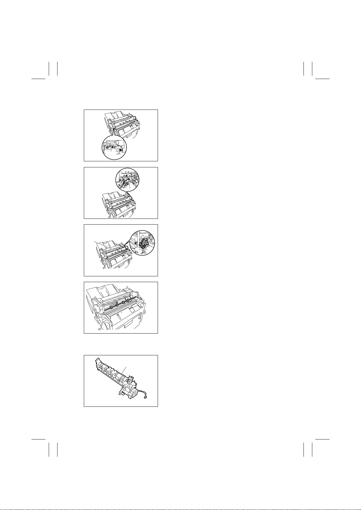
2-8. Removal of the Transport Roller
1. Remove the Upper Door. (Refer to 2-1. (4).)
2. Remove the Upper Cover. (Refer to 2-1. (6).)
3. Remove the Transport Motor Unit. (Refer to 2-7.)
4. Remove the screw [1].
5. Remove the Stopper Ring [2], and remove the
Bushing [3].
[3]
[1]
[2]
4583-102-36
[4]
4583-102-37
6. Remove the two screws [4].
7. Remove the gear [5], and remove the gear [6]
[5]
[8]
[11]
[9]
[10]
[6]
[7]
while disengaging the claw.
8. Remove the Stopper Ring [7], and remove the
Bushing [8].
9. Remove the screw [9], and remove the Entrance
Sensor [10].
10. Remove the Paper Guide (Lower) [11].
4583-102-38
11. Remove the Transport Roller [12].
[12]
4583-102-39
2-9. Removal of the Finisher Exit Roller (Upper)
[1]
1. Remove the Paddle Section. (Refer to 2-5.)
2. Place the Paddle Section [1] as shown in the figure.
4583-102-40
D-14
Page 39
FrameMaker Ver.5.5E(PC) FS-231 OPTION For 8020/8031
02.08.23
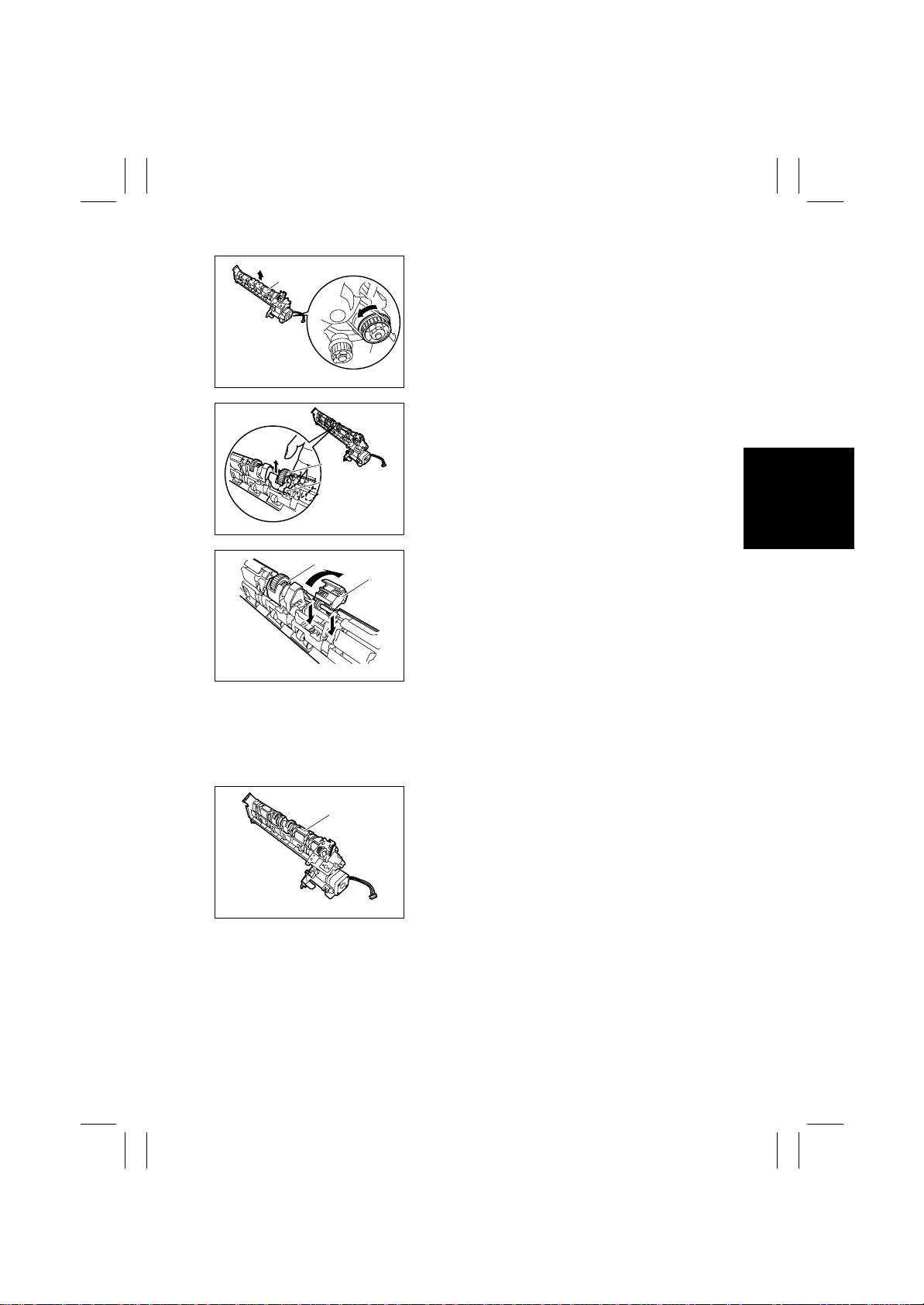
3. Turn the gear [2] in the direction indicated by an
[3]
arrow to move up the Exit Roller (Upper) section
[3].
[2]
4583-102-41
4. Push up the Exit Roller (Upper) [4] from the bottom to release it from the shaft [5].
[4]
[5]
4583-102-42
[6]
4583-102-43
5. Turn up the Exit Roller (Upper) [4], and then push
[4]
6. Remove the front Exit Roller (Upper) [6] as well in
2-10. Removal of the Paddle
1. Remove the Paddle Section. (Refer to 2-5.)
[1]
4583-102-44
2. 2. Place the Paddle Section [1] as shown in the
it down to remove it.
the same way.
figure.
D-15
Page 40
FrameMaker Ver.5.5E(PC) FS-231 OPTION For 8020/8031
02.08.23
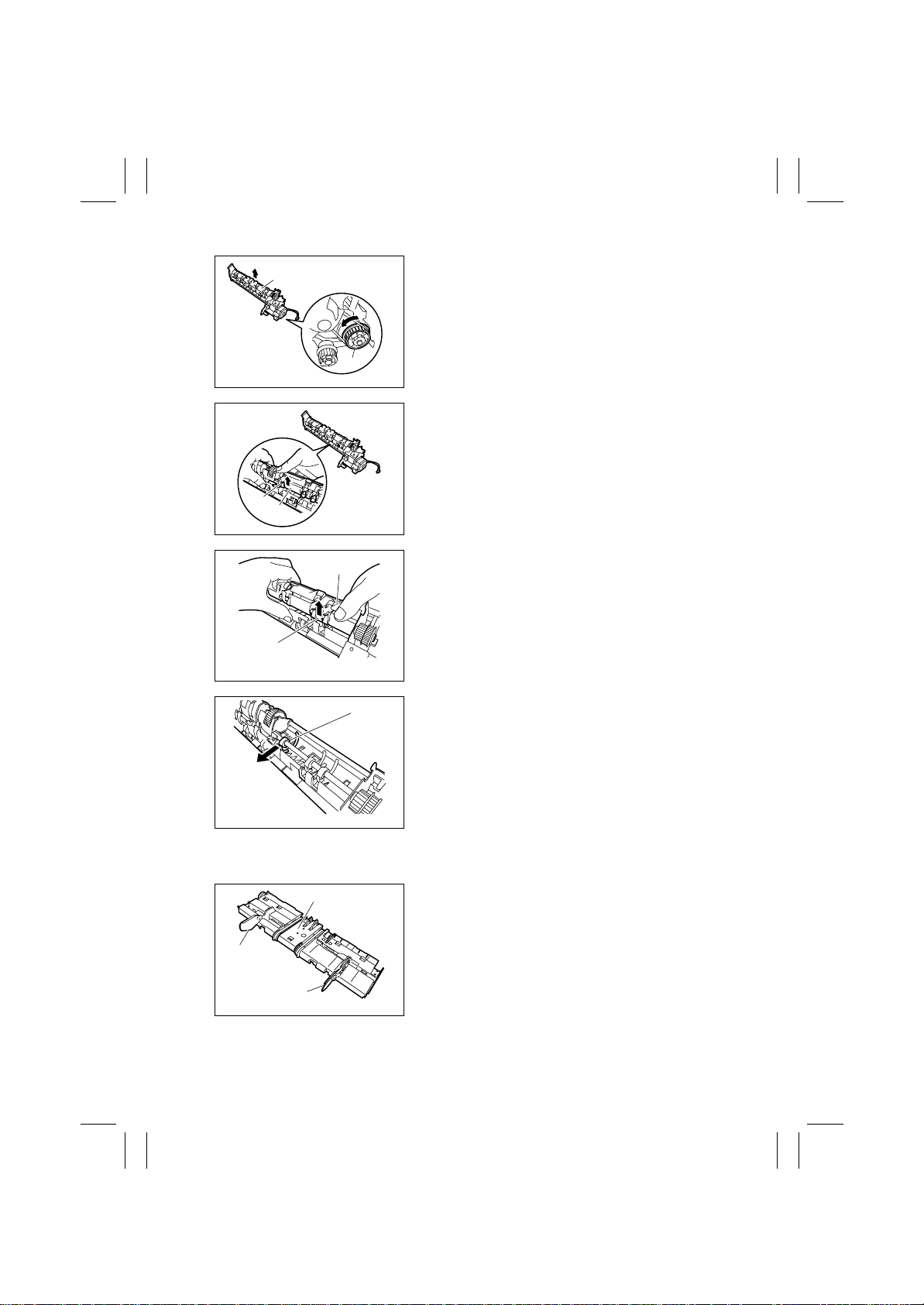
[3]
arrow to move up the Exit Roller (Upper) section
[3].
3. Turn the gear [2] in the direction indicted by an
[2]
4583-102-45
4. Push up the Safety Guide [4] from the bottom to
release it on one side from the shaft [5].
[5]
[4]
[5]
[4]
4583-102-46
4583-102-47
[1]
5. Push up the Safety Guide [4] from the bottom to
release it from the shaft [5] and remove it.
6. Remove the Paddle [6] to the direction indicated
by an arrow.
7. Remove the other Paddles as well in the same
way.
4583-102-48
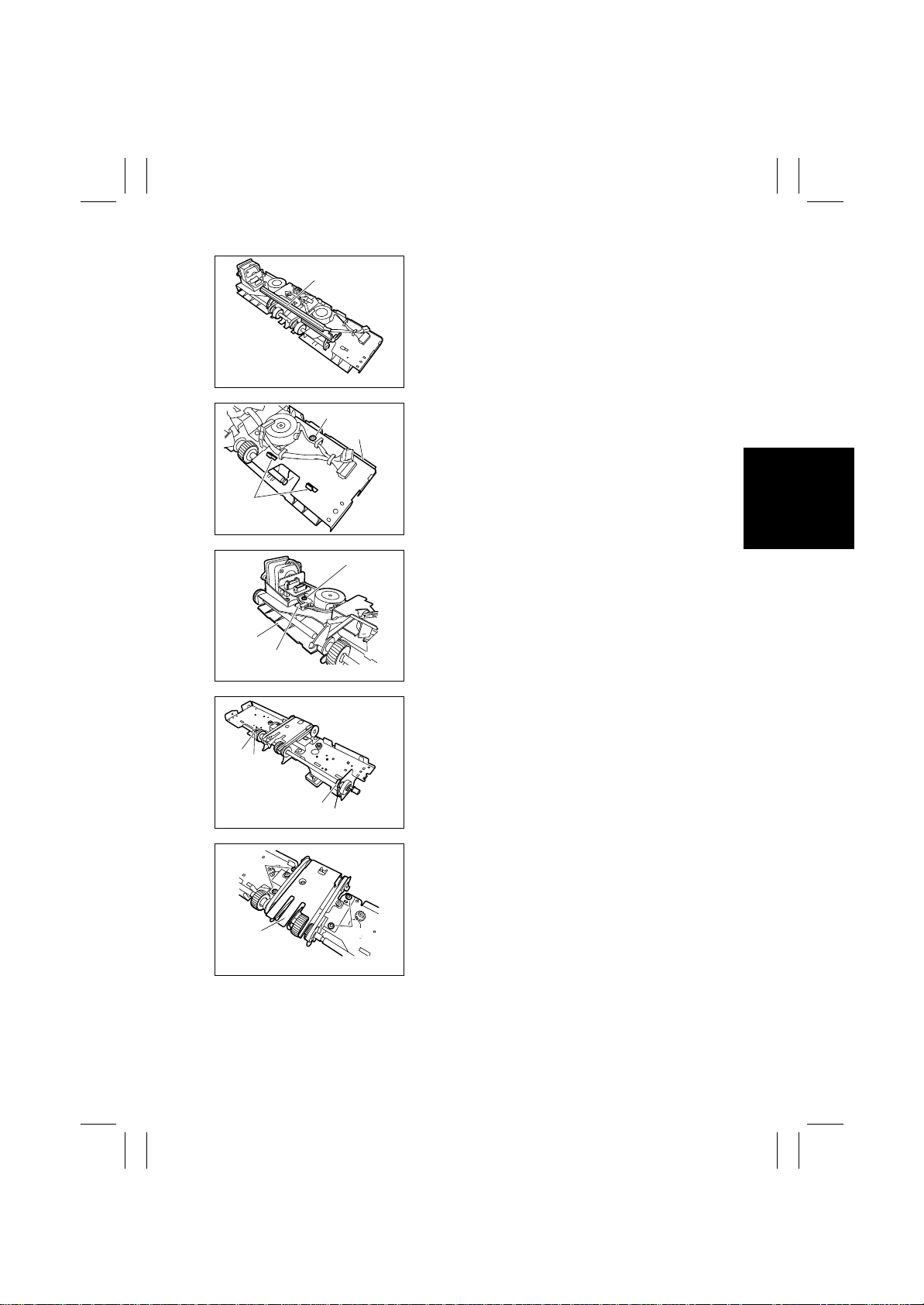
2-11. Removal of the Exit Roller (Lower) and the Paper Exit Belt
[1]
[3]
[2]
4583-102-49
1. Remove the Paddle Section to separate it from
the Finisher Tray. (Refer to 2-5.)
2. 2. Slide the Aligning Plate (Front) [2] and the
Aligning Plate (Rear) [3] outside to remove them
from the Finisher Tray [1].
D-16
Page 41
FrameMaker Ver.5.5E(PC) FS-231 OPTION For 8020/8031
02.08.23
[6]
[10]
[4]
4583-102-50
[5]
[7]
4583-102-51
[8]
[9]
4583-102-52
4. Remove the screw [5], and remove the Paper
Guide (Front) [7] while disengaging the t w o cla ws
[6].
5. Remove the screw [8], and remove the Paper
Guide (Rear) [10] while disengaging the claw [9].
6. Remove the two Stopper Rings [11], and move
the two Bushings [12] inside, respectively.
3. Remove the Finisher Tray Stopper [4].
[12]
[11]
[13]
[14]
[11]
[12]
4583-102-53
7. Remove the four screws [13], and remove the
Exit Roller (Lower) section [14] by lifting it.
[13]
4583-102-54
D-17
Page 42
FrameMaker Ver.5.5E(PC) FS-231 OPTION For 8020/8031
02.08.23
[15]
[16]
4583-102-55
4583-102-56
[17]
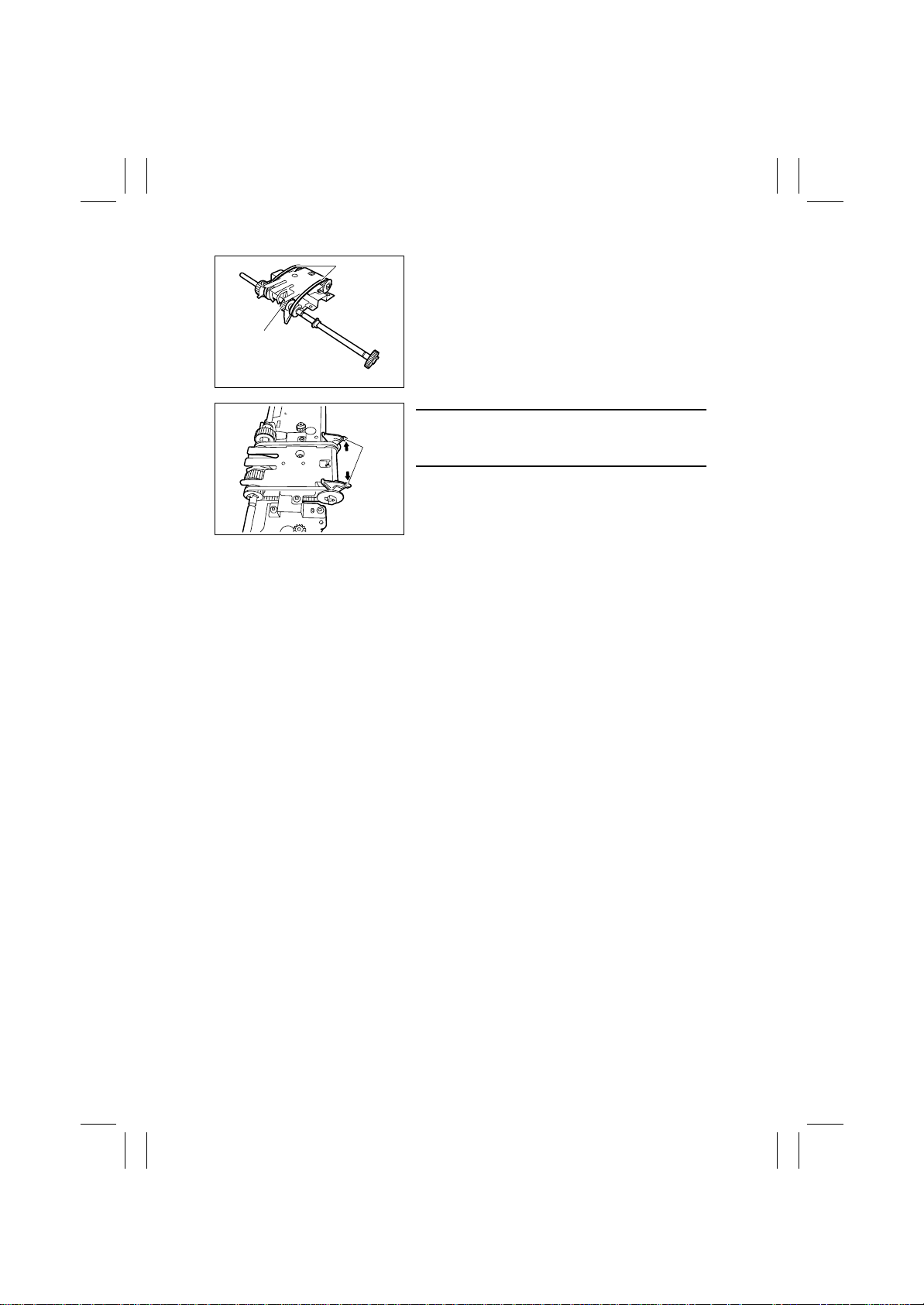
8. Remove the Exit Roller (Lower) [15] and the two
Paper Exit Belts [16].
NOTES
When installing, align the edge of claws of the Paper
Exit Belt [17].
D-18
Page 43
FrameMaker Ver.5.5E(PC) FS-231 OPTION For 8020/8031
02.08.23
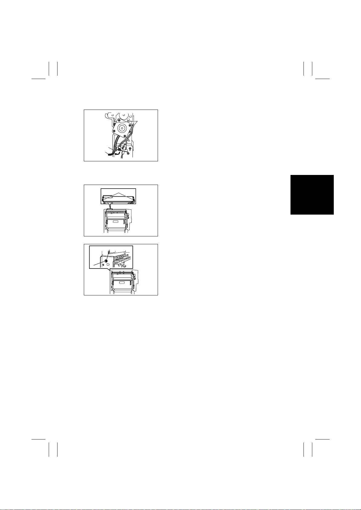
2-12. Removal of the Middle Transport Motor
1. Remove the Middle Rear Cover.
[3]
2. Remove the harness from the Wire Saddle [1],
and remove the harness from the connector [2].
3. Remove the two screws [3].
[1]
[2]
4583-102-60
2-13. Removal of the Middle Transport Roller
[1]
1. Remove the Middle Front and Rear Cover.
2. Remove the screw [1], and remove the Middle
Upper Door.
4583-102-61
[2]
[3]
4583-102-62
3. Remove the Stopper Ring [2], and remove the
Bushing [3].
D-19
Page 44
FrameMaker Ver.5.5E(PC) FS-231 OPTION For 8020/8031
02.08.23
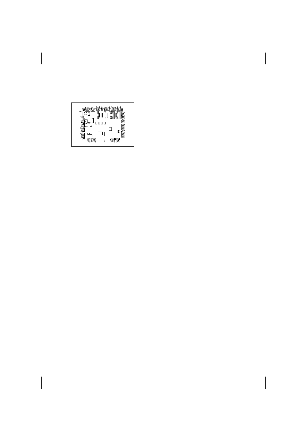
3. Control Board (PCB-CONT)
3-1. Removal of the Finisher Control Board
1. Remove the Rear Cover. (Refer to 2-1. (3).)
2. Unplug the 22 connectors [1], and remove the
[2]
[4]
[3]
screw [2].
3. Release the PCB support [3], and remove the
Finisher Control Board [4].
4583-301-01
D-20
Page 45
FrameMaker Ver.5.5E(PC) FS-231 OPTION For 8020/8031
02.08.23
4. Punch Section (Optional)
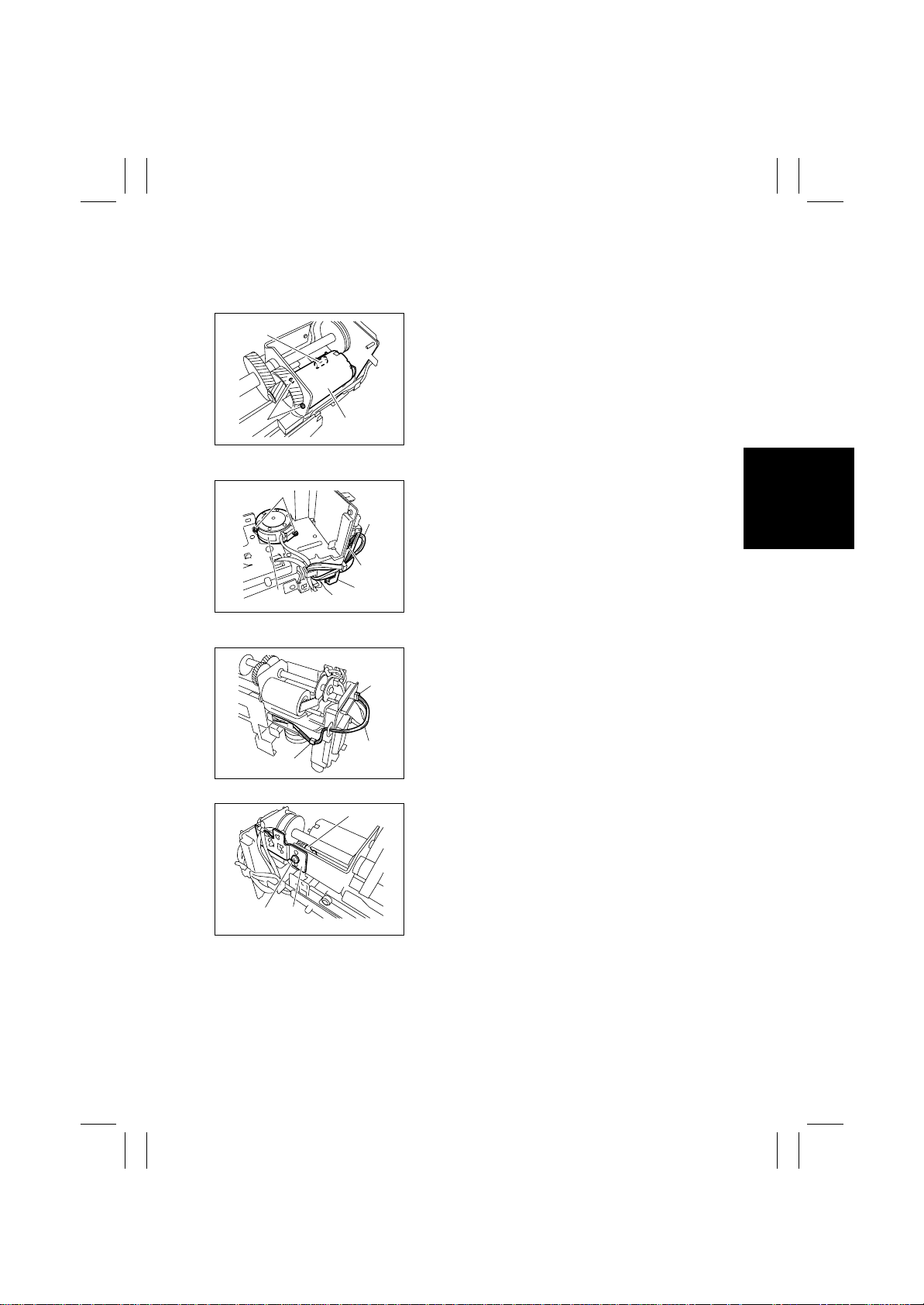
4-1. Removal of the Punch Drive Section
(1) Removal of the Punch Motor
[2]
1. Remove the two screws [1].
2. Unplug the connector [2], and remove the punch
motor [3].
[1]
[3]
4583-401-01
(2) Removal of the Side Registration Motor
[4]
1. Unplug the connector J1001 [1].
2. Remove the Wire Harness [3] from the Wire Harness Guide [2].
3. Remove the two screws [4], and remove the Side
Registration Motor [5].
[3]
[5]
[2]
[1]
4583-401-02
(3) Removal of the Punch Unit
1. Remove the Punch Trash Box.
2. Unplug the connector J1005 [3].
3. Remove the Wire Harness [5] from the Wire Har-
[3]
ness Guide [4].
[5]
[4]
4583-401-04
[6]
4. Unplug the connector [6].
5. Remove the screw [8], and remove the Sensor
Support Plate [7].
[7]
[8]
4583-401-05
D-21
Page 46
FrameMaker Ver.5.5E(PC) FS-231 OPTION For 8020/8031
02.08.23
6. Remove the screw [9] and the washer [10].
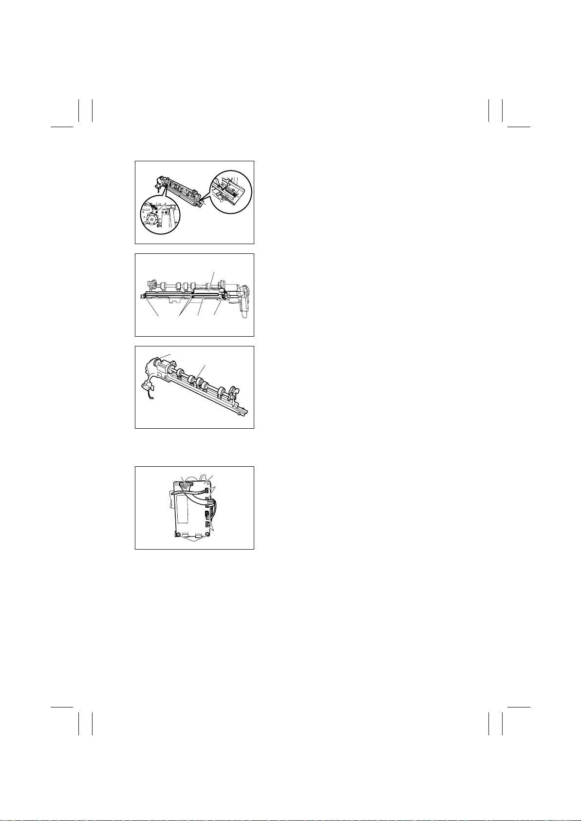
7. Unplug the connector [11].
[9]
8. Remove the two screws [12], and remove the
[11]
[12]
[13]
[10]
4583-401-06
base cover [13].
9. Remove the four screws [14], and remove the
[15]
Sensor Unit (Upper) [15] and the Sensor Unit
(Lower) [16].
[14] [14] [14]
[17]
[16]
[18]
4583-401-07
10. Remove the Punch Unit [18] from the Side Registration Motor section [17].
4583-401-08
4-2. Removal of the Punch Board Section
(1) R e m oval of the Punch Control B oa rd
[2]
[3]
[2]
[2]
[1]
4583-402-01
1. Remove the two screws [1].
2. Unplug the five connectors [2], and remove the
Punch Control Board [3].
D-22
Page 47
FrameMaker Ver.5.5E(PC) FS-231 OPTION For 8020/8031
02.08.23
5. ADJUSTMENT
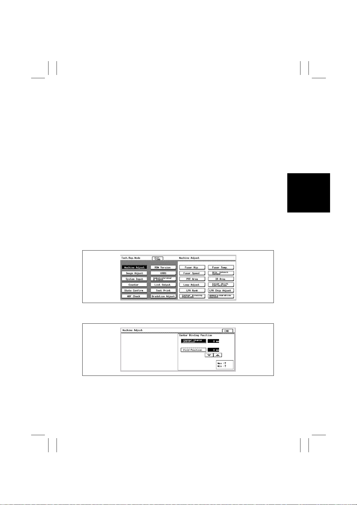
5-1. Adjustment of the Stapling Position
The stapling position is adjusted by aligning the stapling position to the folding position.
This adjustment is made in the Tech. Rep . Mode of the main unit. Since the adjustment is
made in increments of 1mm, this adjustment is useful for eliminating a displacement of
1mm or more.
For the effective adjustment of a minimal displacement smaller than 1mm, refer to
"SWITCHES ON PCB"
Adjustable range: -7 to +7mm (Increment: 1mm)
(1) ADF-equipped machin e
1. Set A3 or 11 x 17" to the Feed Tray.
2. Select Original ‚Copy --> 4in1 / Booklet -->
Booklet Creation --> Booklet.
3. Set five sheets of A3 or 11 x 17" original (blank
paper acceptable) in the Original T ray.These five
sheets are used for adjustment to minimize variation.
4. Press the Start Key.
5. Set the mode to the Tech. Rep. Mode.
6. Touch "Machine Adjust."
7. Touch "Center Binding Position."
8. Touch "Center-Staple Position."
D-23
k4583s031
4583s032
Page 48
FrameMaker Ver.5.5E(PC) FS-231 OPTION For 8020/8031
02.08.23
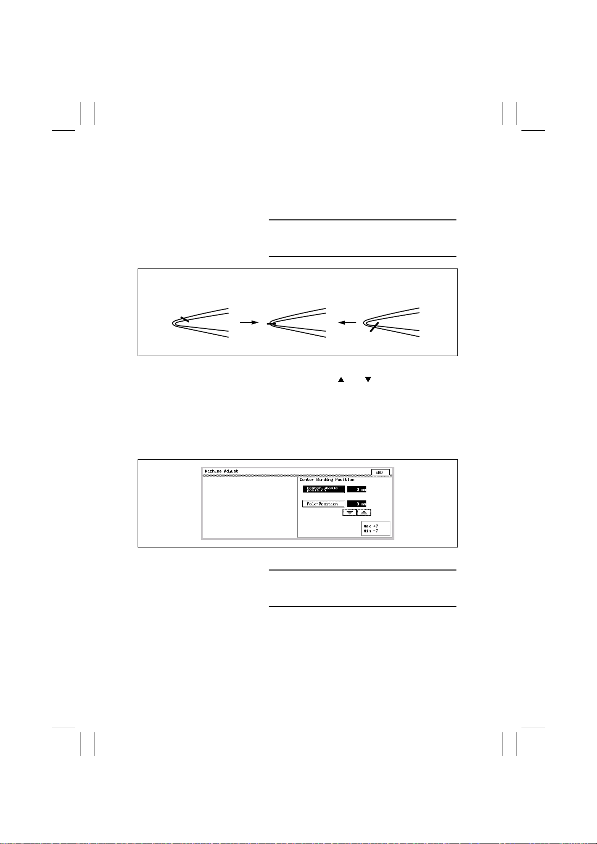
9. Renew the center folding of the finished copies.
• Take the top surface of the finished copies as "A,"
and the under surface as "B."
10. Check the deviation of the stapling position from
the newly folded position.
NOTES
In checking the deviation, refer not to the folded position by the Finisher but to the newly folded position.
Standard:0+/-2mm
<To - side>
<Standard>
A
<To + side>
AA
B
4698U068AA 4698U069AA
BB
11. Press the Clear Key.
12. Adjust with the and Keys.When the stapling position is shifted to the direction A: Adjust
the value to the - side.When the stapling position
is shifted to the direction B: Adjust the value to
the + side.
13. Touch "OK."
14. Select "Booklet Creation" and take copies.
NOTES
Set five or more sheets of original under the ADF,
and then take copies and bind them into a booklet.
4698U070AA
4583s032
D-24
Page 49

FrameMaker Ver.5.5E(PC) FS-231 OPTION For 8020/8031
02.08.23
(2) ADF-unequipped machine
1. Set A3 or 11 x 17" to the Tray.
2. Select Original‚ Copy --> 4in1 / Booklet -->
Booklet Creation --> Booklet.
3. Set A3 or 11 x 17" original (blank paper acceptable) on the Original Glass.
4. Press the Start Key five times (to cause reading
operation five times) Adjust the variation to the
minimum by using five sheets.
5. Press the "Read End" Key.
6. Press the Start Key.
7. Take the Steps from 5 to 14 of (1) "ADF-equipped
machine" in "5-1. Adjustment of the Stapling
Position."
D-25
Page 50
FrameMaker Ver.5.5E(PC) FS-231 OPTION For 8020/8031
02.08.23
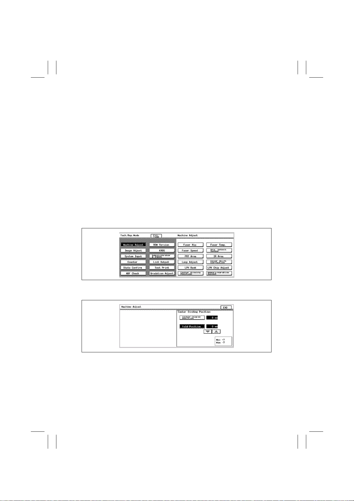
5-2. A djustment of the Folding Position
The folding position is adjusted by aligning the folding position to the stapling position.
This adjustment is made in Tech. Rep. Mode of the main body of the copier when any PCB
in the Finisher Controller has been replaced or the folding position has to be changed for
some reasons.
Adjustment range: -7 to +7mm (Increment: 1mm)
(1) ADF-equipped machin e
1. Return to the basic screen.
2. Select Original ‚Copy --> 4in1 / Booklet -->
Booklet Creation --> Booklet.
3. Set five sheets of A3 or 11 x 17" original (blank
paper acceptable) in the Original T ray.These five
sheets are used for adjustment to minimize variation.
4. Press the Start Key.
5. Set the mode to the Tech. Rep. Mode.
6. Touch "Machine Adjust."
7. Touch "Center Binding Position."
8. Touch "Fold-Position."
D-26
k4583s031
4583s033
Page 51
FrameMaker Ver.5.5E(PC) FS-231 OPTION For 8020/8031
02.08.23
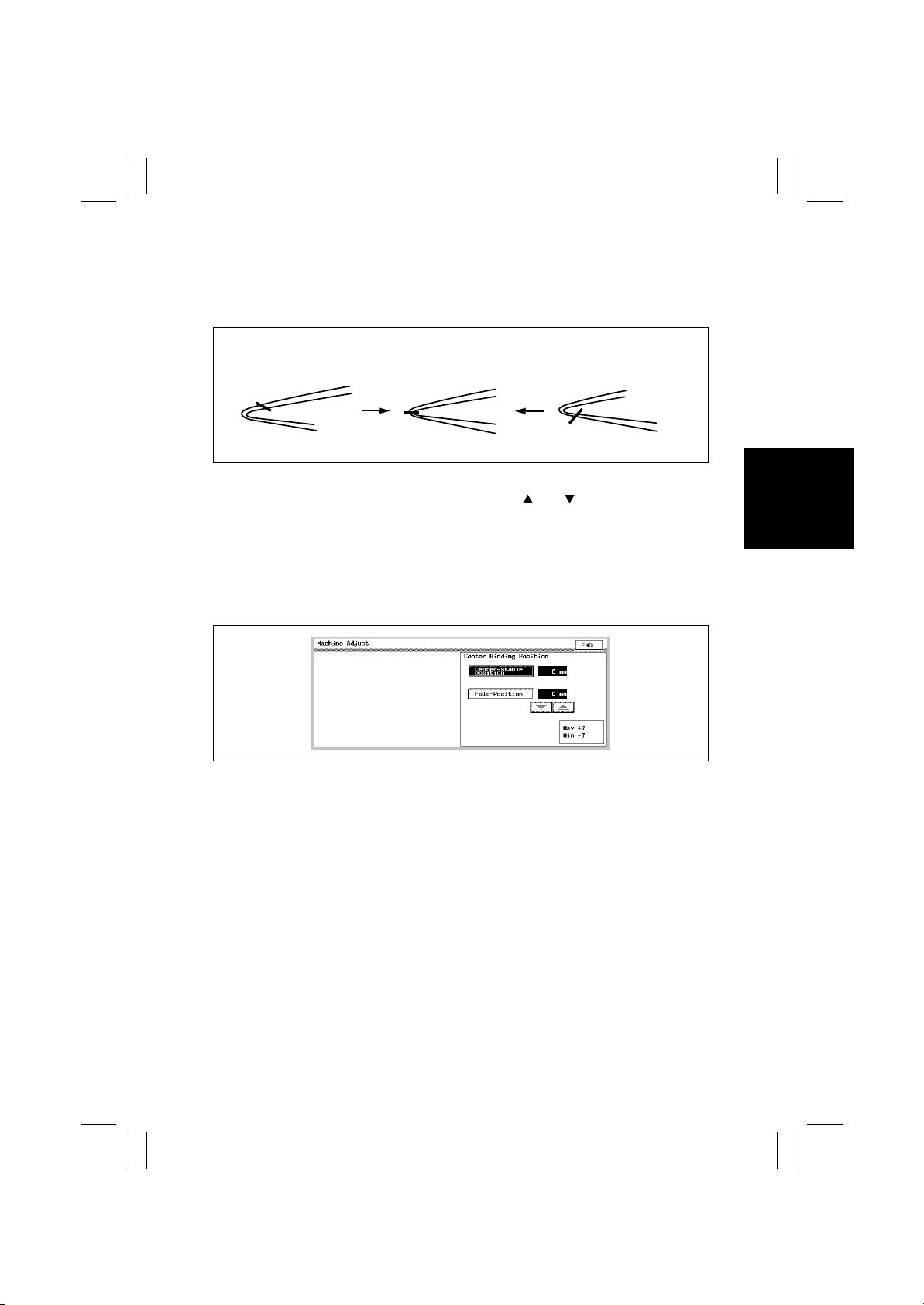
9. Check the finished copies for deviation of the stapling position of from the newly folded position.
• Take the top surface of the finished copies as "A,"
and the under surface as "B."
Standard : 0
2mm
+/-
<To + side>
A
B
4698U112AA 4698U069AA
10. Press the Clear Key.
11. Adjust with the and Keys.When the sta-
12. Touch "OK."
13. Select the booklet of "Booklet Creation" and take
<Standard>
A
B
<To - side>
A
B
4698U113AA
pling position is shifted to the direction A: Adjust
the value to the + side.When the stapling position
is shifted to the direction B: Adjust the value to
the - side.
4583s032
copies. Check the stapling position. If the posi tion
is displaced, redo the procedure from Step 5.
D-27
Page 52

FrameMaker Ver.5.5E(PC) FS-231 OPTION For 8020/8031
02.08.23
(2) ADF-unequipped machine
1. Return to the basic screen.
2. Select Original ‚Copy --> 4in1 / Booklet -->
Booklet Creation --> Booklet.
3. Set A3 or 11 x 17" original (blank paper acceptable) in the tray for original.
4. Press the Start Key five times (to cause reading
operation five times) Adjust the variation to the
minimum by using five sheets.
5. Touch the "Finish" of the panel.
6. Press the Start Key.
7. Take the Steps from 5 to 13 of (1) "ADF-equipped
machine" in "5-2. Adjustment of the Folding Position."
D-28
Page 53
FrameMaker Ver.5.5E(PC) FS-231 OPTION For 8020/8031
02.08.23
5-3. Adjustment of Height and Inclination
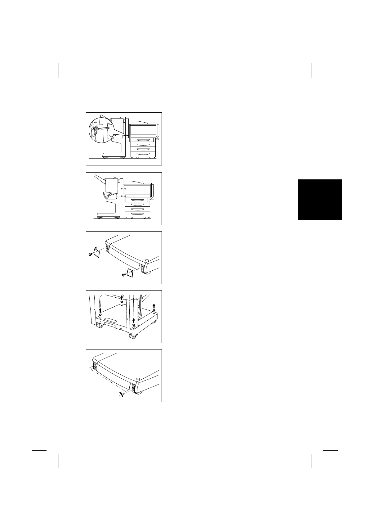
1. Bring Finisher slowly closer to the main unit, and
check to confirm the following points:
• The positioning pin is on a level with the hole in the
Finisher.
4698U061AA
• The Horizontal Transport section is not on the
extreme slant.
A
B
4698U060AA
• The clearances A and B are uniform.
Make the necessary adjustments by using the following order:
2. Remove the Finisher from the main unit, and
remove the two caster covers.
4698U062AA
4698U063AA
4698U064AA
3. Remove the four adjustment screw covers.
4. Loosen the four caster fixing screws, two f or each
caster.
D-29
Page 54
FrameMaker Ver.5.5E(PC) FS-231 OPTION For 8020/8031
02.08.23
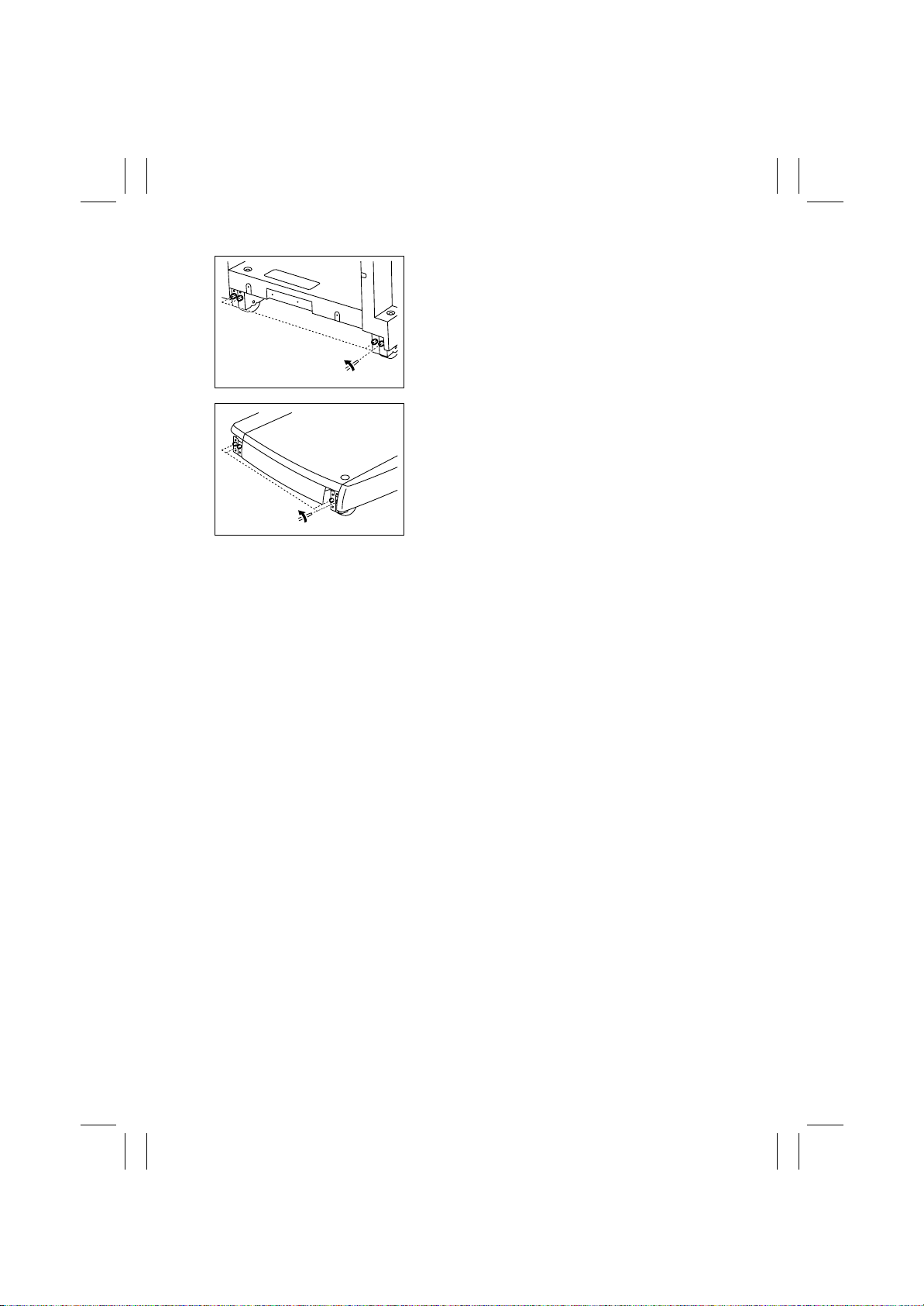
4698U099AA
5. Turn the adjustment screw to make adjustment.
• To heighten: Turn the screw counterclockwise.
• To br ing down: Turn the screw clockwise.
6. Fasten the caster fixing screws.
7. Install the caster covers and the adjustment
screw covers.
4698U064AA
D-30
Page 55

FrameMaker Ver.5.5E(PC) FS-231 OPTION For 8020/8031
02.08.23
TROUBLESHOOTING
Page 56

FrameMaker Ver.5.5E(PC) FS-231 OPTION For 8020/8031
02.08.23
Blank page
Page 57
FrameMaker Ver.5.5E(PC) FS-231 OPTION For 8020/8031
02.08.23
1. SENSOR CHECK
• To ensure an easy and safe check for sensor operation, signals can be checked whether
they are properly input or not by checking the sensor input data when the machine is in
the standby state (including misfeed, malfunction and setting failure conditions).
1-1. Sensor Check Screen
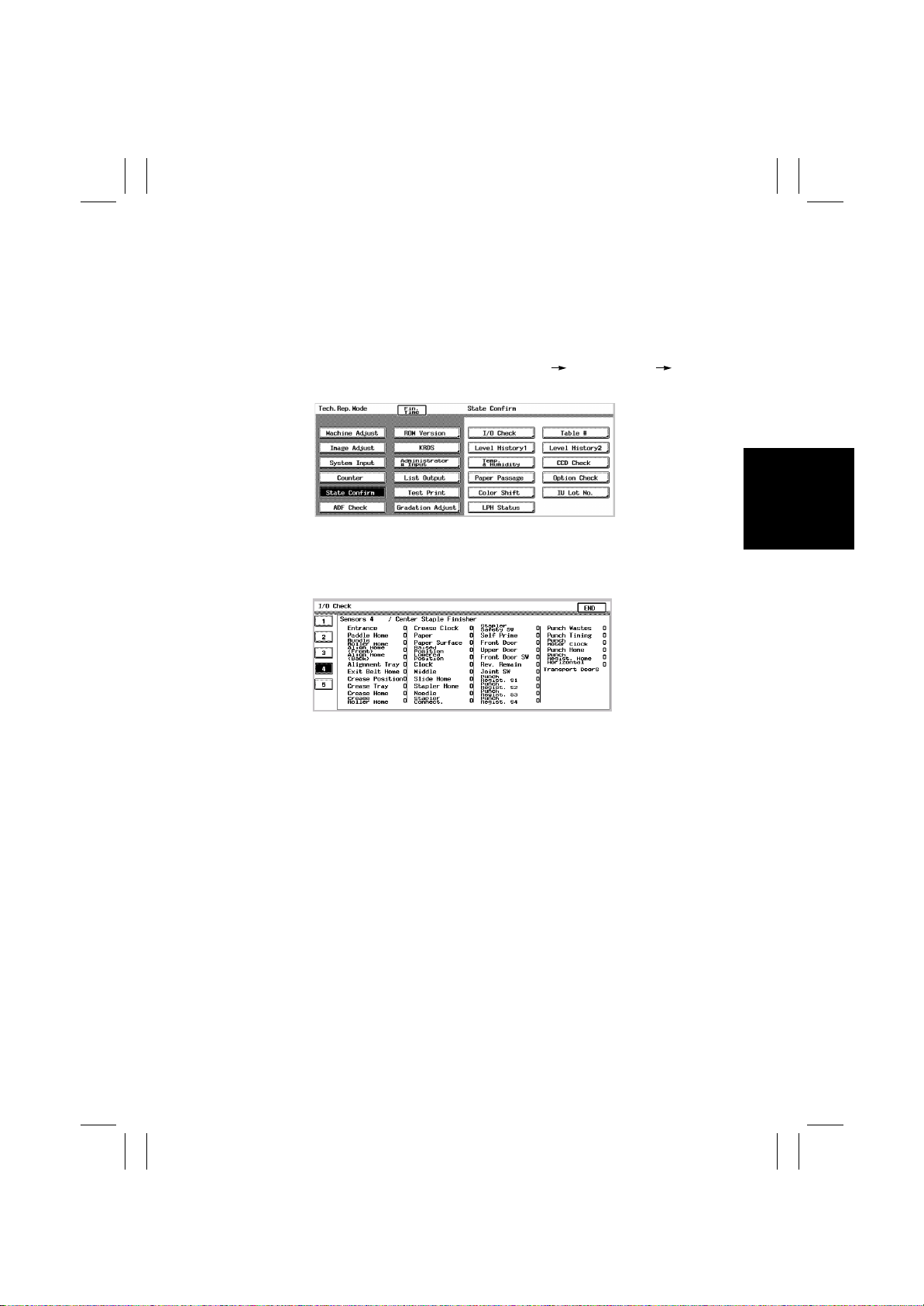
• Select the function in the following order: Tech. Rep. Mode State Confirm I/O
Check.
k4583S034
• A sample screen is shown below. Note that the port data may not be displayed e xactly as
shown.
<Sensor Monitor 4>
T-1
4583S035
Page 58

FrameMaker Ver.5.5E(PC) FS-231 OPTION For 8020/8031
02.08.23
1-2. Sensor Check Procedure
1. When a misfeed or malfunction occurs, select the function in the following order:
2. Tech. Rep. Mode St ate Confir m I/O Check Sensors 4.
3. Check the input of the sensor that is probably defective.
(Example)
When a misfeed occurs, the First Tray Exit Sensor is considered to be defective:
<Procedure>
1. Remove the sheet of misfed paper to reset the misfeed.
2. Select the function in the following order: Tech. Rep. Mode State Confirm I/O
Check Sensors 4.
3. Check that the data of "First Tray Exit S" is "0" on the screen.
4. Check that the data has changed from "0" to "1" by blocking the light f or the First Tray
Exit Sensor (PC1).
1: PC1 is operational. 0: PC1 is faulty.
T-2
Page 59
FrameMaker Ver.5.5E(PC) FS-231 OPTION For 8020/8031
02.08.23
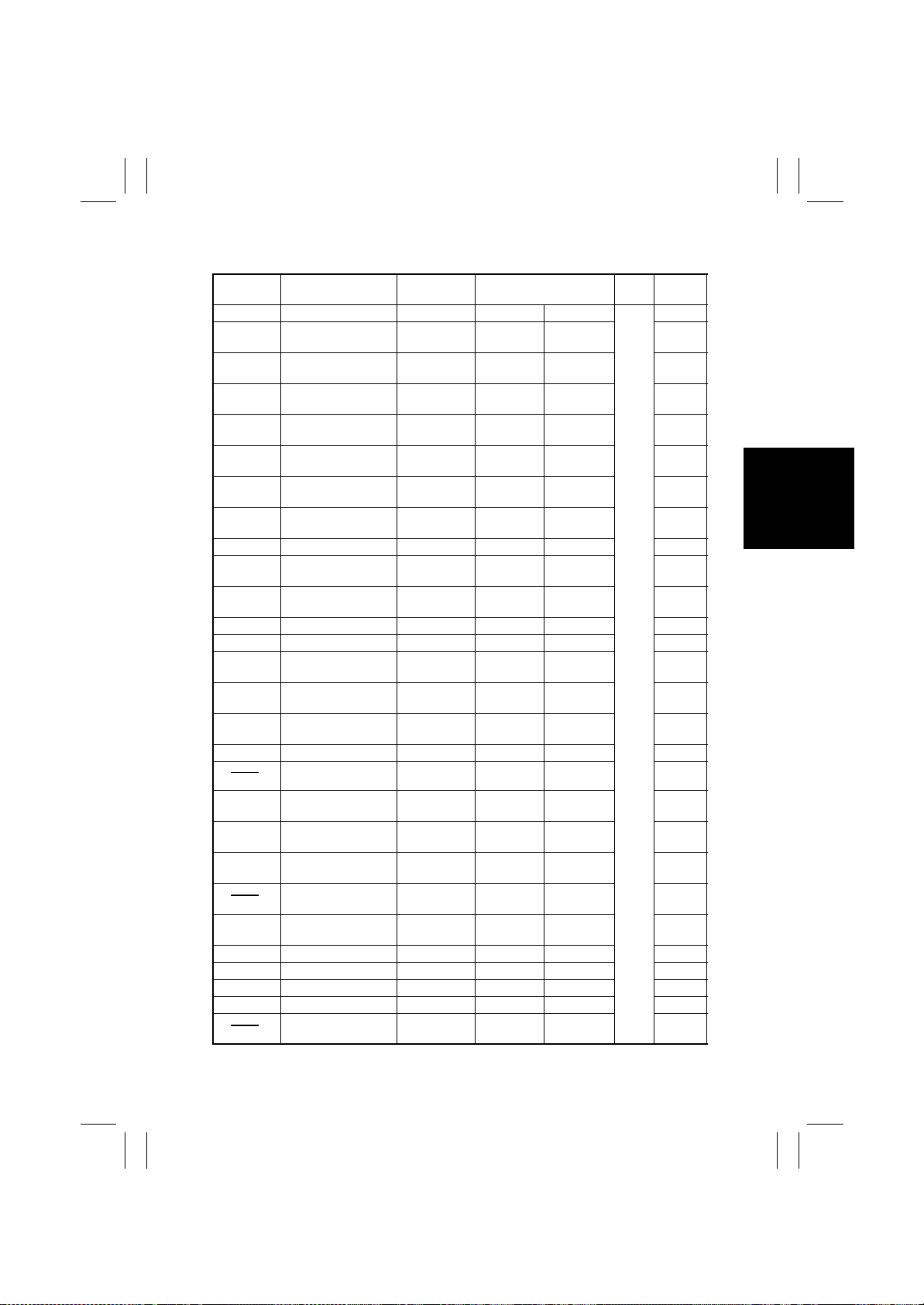
1-3. Sensor Check List
Symbol Panel Display Signal Name
PI1
PI2
PI3
PI4
PI5
PI6
PI7
PI10
PI13
PI11
PI12
PI14
PI8
PI9
PI15
PI16
PI17
PI18
PI19
PI20
MS3
PI21
PI22
PI23
MS1
Entrance Sensor ENT-S
Paddle Home
Position Sensor
Bundle Roller Home
Position Sensor
Align Home Position
Sensor
Rear Align Home
Position Sensor
Alignment Tray
Sensor
Exit Belt Home
Position Sensor
Crease Position
Sensor
Crease Tray Sensor BIND-EMPS
Crease Home
Position Sensor
Crease Roller Home
Position Sensor
Crease Clock Sensor BIND- CLK
Paper Sensor TRAY-EMPS
Paper Surface
Detecting Sensor
Raised (Upper Limit)
Position Sensor
Lowered (Lower
Limit) Position Sensor
Lift Clock Sensor SIFT-CLK
Lift Middle Sensor
Slide Home Position
Sensor
Stapler Home
Position Sensor
Staple Detecting
Sensor
Stapler Connecting
Sensor
Stapler Safety Switch STPLSAFE-
Self Prime Sensor SELF-P
Front Door Sensor FDOOR-S
Upper Door Switch TOPCOV-S
Front Door Switch FDOOR-SW
Reverse Remain Sen-
sor
PDL-HP
BDL-ROL-HP
FJOG-HP
RJOG-HP
ADJ-TRAY-S
EJCT-BLT-HP
BIND-POS
BIND-HP
BIDL-ROLHP
LVL-S
SIFT-UPLMT
SIFT-DNLMT
SLID-HP
STPL-HP
HOOK-S
STPL-CNCT
SW
Operational Characteris-
tics /Panel Display
SUPPLIED EMPTY
HP CN9-3
HP CN9-4
HP CN4-3
HP CN5-15
EMPTY SUPPLIED CN5-3
HP CN5-6
EMPTY SUPPLIED CN16-2/3
EMPTY SUPPLIED CN15-3
HP CN16-6
HP CN16-9
EMPTY SSUPPLIED CN5-9
DETECTED CN5-12
UPPER
LIMIT
LOWER
LIMIT
FULL CN
HP CN11-3
HP CN11-4
EMPTY SUPPLIED CN11-5
DETECTED CN11-1
OPEN CN8-1
READY CN11-6
OPEN CN4-9
OPEN CN4-6
OPEN CN8-2/3
HORIZON-
TAL
Input
PCB
PCB
CONT
CN/PJ
No.
CN16-12
CN9-5
CN15-9
CN15-12
CN15-6
T-3
Page 60
FrameMaker Ver.5.5E(PC) FS-231 OPTION For 8020/8031
02.08.23
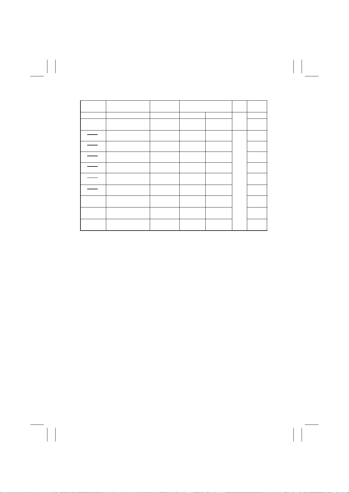
Symbol Panel Display Signal Name
MS2
PC4
PI3P
PI1P
PI2P
Joint Switch JOINT-SW
Horizontal Unit Door
Sensor
Punch Regist. S1
Punch Regist. S2
Punch Regist. S3
Punch Regist. S4
Punch Wastes
Sensor
Punch Timing Sensor PNCH-TIM-S
Punch Motor Clock
Sensor
Punch Home
Position Sensor
Punch Regist. Home
Position Sensor
HTD
CLOCK
PUNCH
SLIDE
Operational Characteris-
tics /Panel Display
OPEN CN8-4/5
OPEN CN21-8
FULL
BLOCK J1006-9
HP J1006-6
HP J1006-3
Input
PCB
PCB
P
CONT
CN/PJ
No.
CN12-5
T-4
Page 61
FrameMaker Ver.5.5E(PC) FS-231 OPTION For 8020/8031
02.08.23
2. MISFEED DETECTION AND TROUBLESHOOTING PROCEDURES
2-1. Outline
The check timing for detecting misfeed at the Finisher Saddle Punch (optional) is registered
beforehand in the microcomputer (CPU) on the Finisher Control Board. With this check timing, the occurrence of misfeed is determined by judging whether there is paper in the sensor sections. When misfeed occurs, the Finisher Control Board sends the details of the
misfeed to the units.
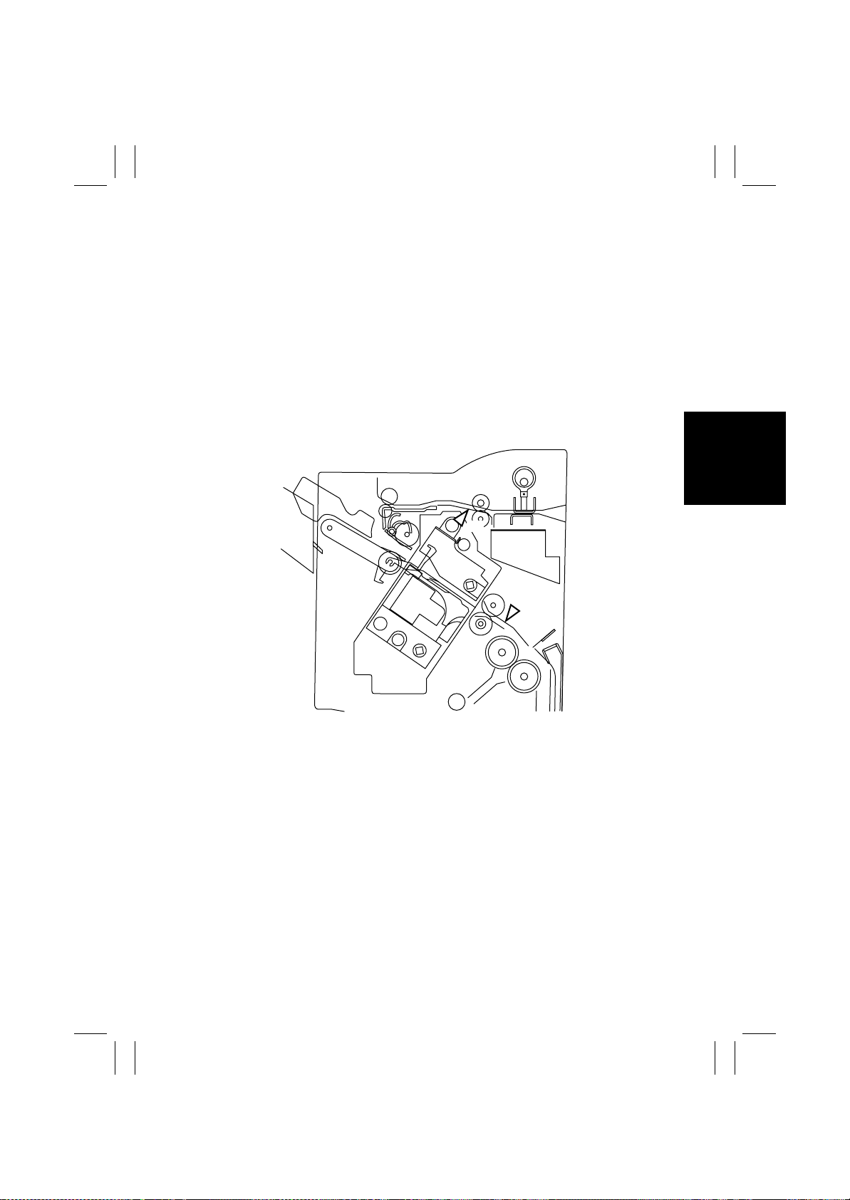
2-2. Locations of the Misfeed Sensors
PI1
PI1: Entrance Sensor
PI10: Crease Position Sensor
PI10
4583-202-02
T-5
Page 62
FrameMaker Ver.5.5E(PC) FS-231 OPTION For 8020/8031
02.08.23
2-3. Misfeed Detection
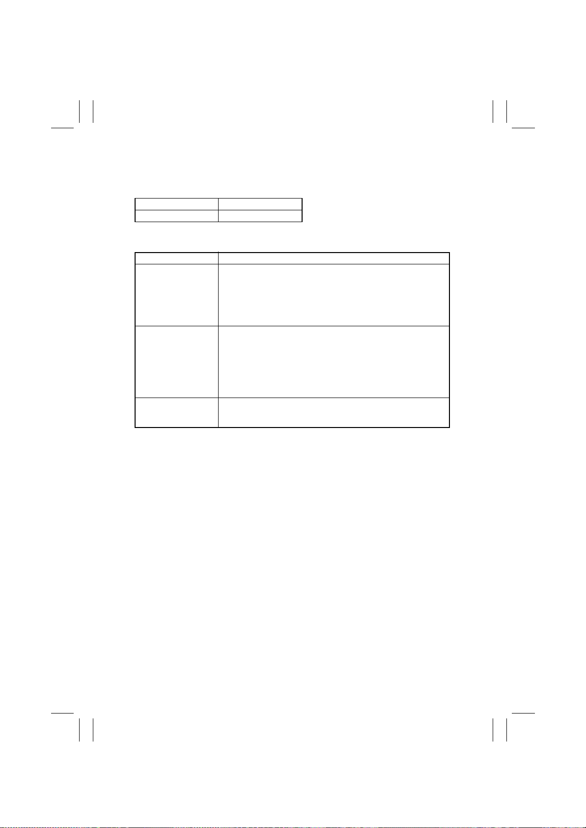
• When misfeed occurs, message, misfeed location and paper location are displayed on
the Touch Panel of the copier.
Misfeed location Blinking.
Paper location Lighting.
• The misfeed display can be released by resetting this unit to the copier.
Type Detection Timing
Transport misfeed
Folding position misfeed
Stapler misfeed The Stapler Home Position Sensor (PI19) is not turned OFF or does not
• The Entrance Sensor does not detect paper even after the
lapse of approx. 1.5 sec. after the Entrance Sensor has
received the paper exit signal from the main unit.
• Paper is not removed from the Entrance Sensor (PS1) even
after the lapse of approx. 2 sec. after the Entrance Sensor has
detected paper edge.
• The Crease Position Sensor does not detect paper even after
the lapse of 1200 msec. after the paper has been fed from the
Transport Booklet Tray to the stapling position during stapling
operation.
• Paper is not removed from the Crease Position Sensor ev en
after the lapse of approx. 10.5 sec. after the Stapler/Folding
Monitor has been driven during stapling operation.
return to its home position even after the lapse of 600 msec. after the stapler has been driven.
T-6
Page 63

FrameMaker Ver.5.5E(PC) FS-231 OPTION For 8020/8031
02.08.23
3. MALFUNCTIONS DETECTION AND TROUBLESHOOTING PROCEDURES
3-1. Malfunctions Detection
• Any of the following operational failures are detected, and the malfunction codes are
shown on the panel display of the main unit.
• Open/close the Front Door of the main unit for troubleshooting.
Note:
Before starting the troubleshooting in relation to the Punch Mechanism C0B7X, be sure to
turn OFF the POWER switch of the main unit.
Code Description
COB0X
COB2X
COB3X
COB4X
COB5X
COB7X
COB81
Finisher/Sorter Transport Drive
Stapler Unit Drive
Finisher Alignment System
Finisher Booklet Transport Mechanism
Stapler Mec hanism
Punch Mechanism
Shift Mechanism
T-7
Page 64
FrameMaker Ver.5.5E(PC) FS-231 OPTION For 8020/8031
02.08.23
3-2. Troub leshooting Procedures for Each Malfunction Code
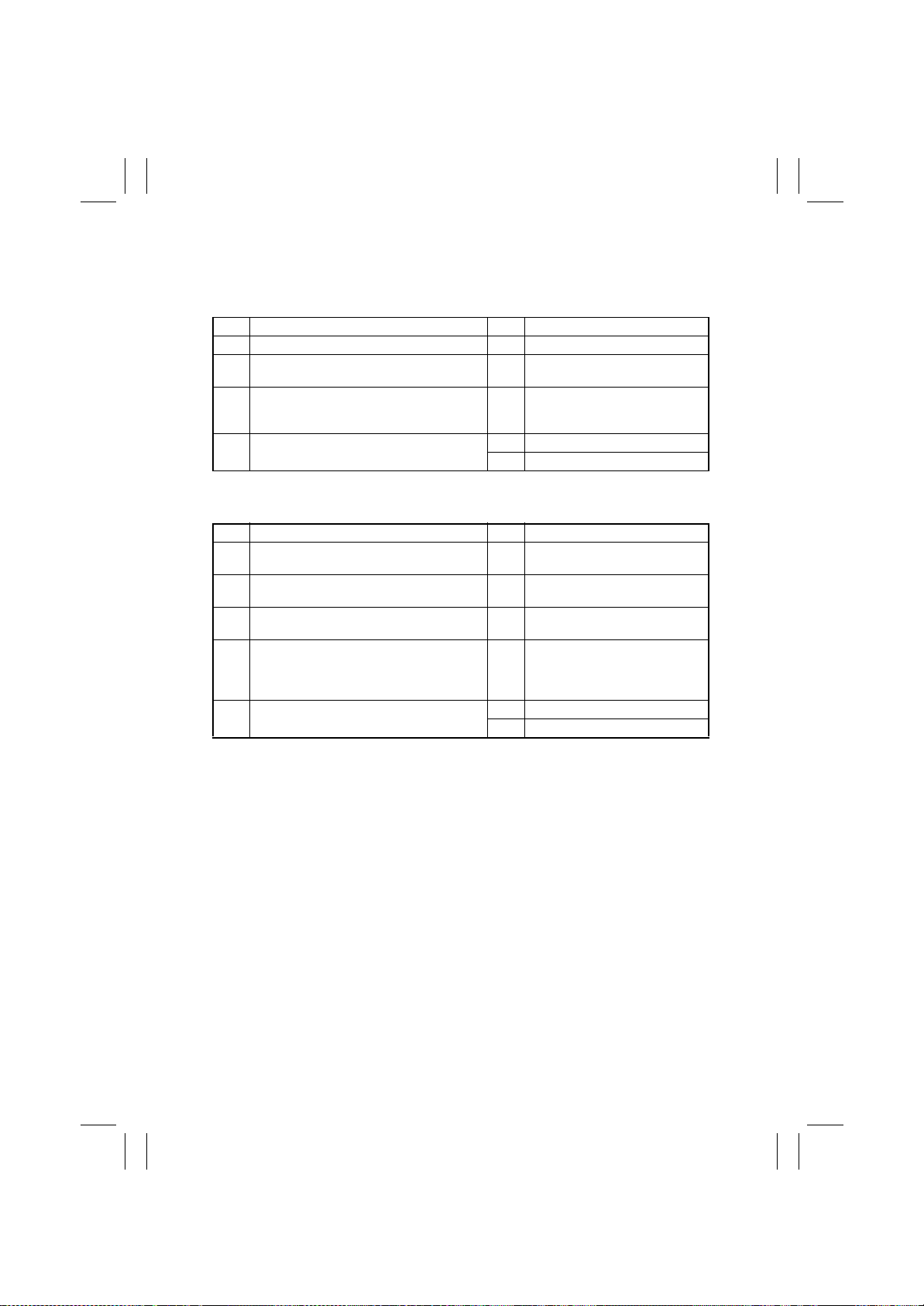
(1) C0B00 Transport System Drive malfunctions
Step Check Item Result Action
Does the sensor operate normally? NO Replace the sensor.
1
Is the wiring between the Control Board and
2
the Transport Motor correct?
When the Booklet Transport Roller Shaft is
turned manually, does the Booklet Roller move
3
up/down normally?
Is the malfunction fixed when the Transport
4
Motor is replaced?
(2) C0B05 Paddle Motor malfunctions
Step Check Item Result Action
Does the Paddle Home Position Sensor oper-
1
ate normally?
Does the Oscillating Guide Home Position Sen-
2
sor operate normally?
Is the wiring between the Control Board and
3
the Paddle Motor correct?
When the Paddle Motor is turned forward/
backward manually, is the rotation of the Pad-
4
dle or up/down movement of the Oscillating
Guide caught mechanicall y?
Is the malfunction fixed when the Paddle Motor
5
is replaced?
NO Correct the wiring.
NO Adjust the mechanism.
YES End.
NO Replace the Control Board.
Replace the sensor.
NO
Replace the sensor.
NO
Correct the wiring.
NO
Adjust the mechanism.
YES
End.
YES
Replace the Control Board.
NO
T-8
Page 65
FrameMaker Ver.5.5E(PC) FS-231 OPTION For 8020/8031
02.08.23
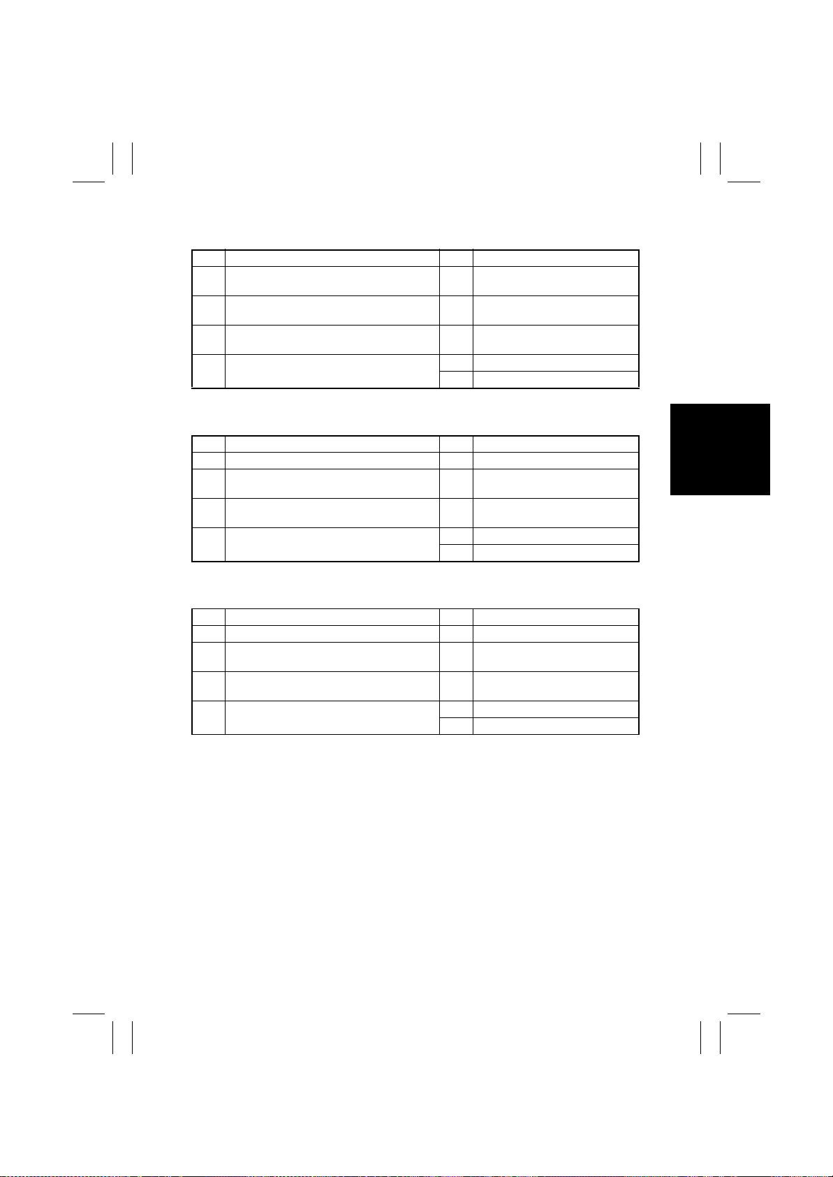
(3) C0B25 Stapler Unit Slide Motor malfunctions
Step Check Item Result Action
Does the Slide Home Position Sensor operate
1
normally?
Is the wiring between the Control Board and
2
the Slide Motor correct?
Is the movement of the Stapler caught mechan-
3
ically in its route?
Is the malfunction fixed when the Slide Motor is
4
replaced?
Replace the sensor.
NO
Correct the wiring.
NO
Adjust the mechanism.
YES
End.
YES
Replace the Control Board.
NO
(4) C0B39 Front Aligning Plate Motor malfunctions
Step Check Item Result Action
Does the sensor operate normally? NO Replace the sensor.
1
Is the wiring between the Control Board and
2
the Front Aligning Motor correct?
Is the movement of the Aligning Pate caught
3
mechanically in its route?
Is the malfunction fixed when the Front Aligning
4
Motor is replaced?
NO Correct the wiring.
YES Adjust the mechanism.
YES End.
NO Replace the Control Board.
(5) C0B3A Rear Aligning Plate Motor malfunctions
Step Check Item Result Action
1 Does the sensor operate normally?
2 Is the wiring between the Control Board and
the Rear Aligning Motor correct?
3 Is the movement of the Aligning Pate caught
mechanically in its route?
4 Is the malfunction fixed when the Rear Aligning
Motor is replaced?
Replace the sensor.
NO
Correct the wiring.
NO
Adjust the mechanism.
YES
End.
YES
Replace the Control Board.
NO
T-9
Page 66
FrameMaker Ver.5.5E(PC) FS-231 OPTION For 8020/8031
02.08.23
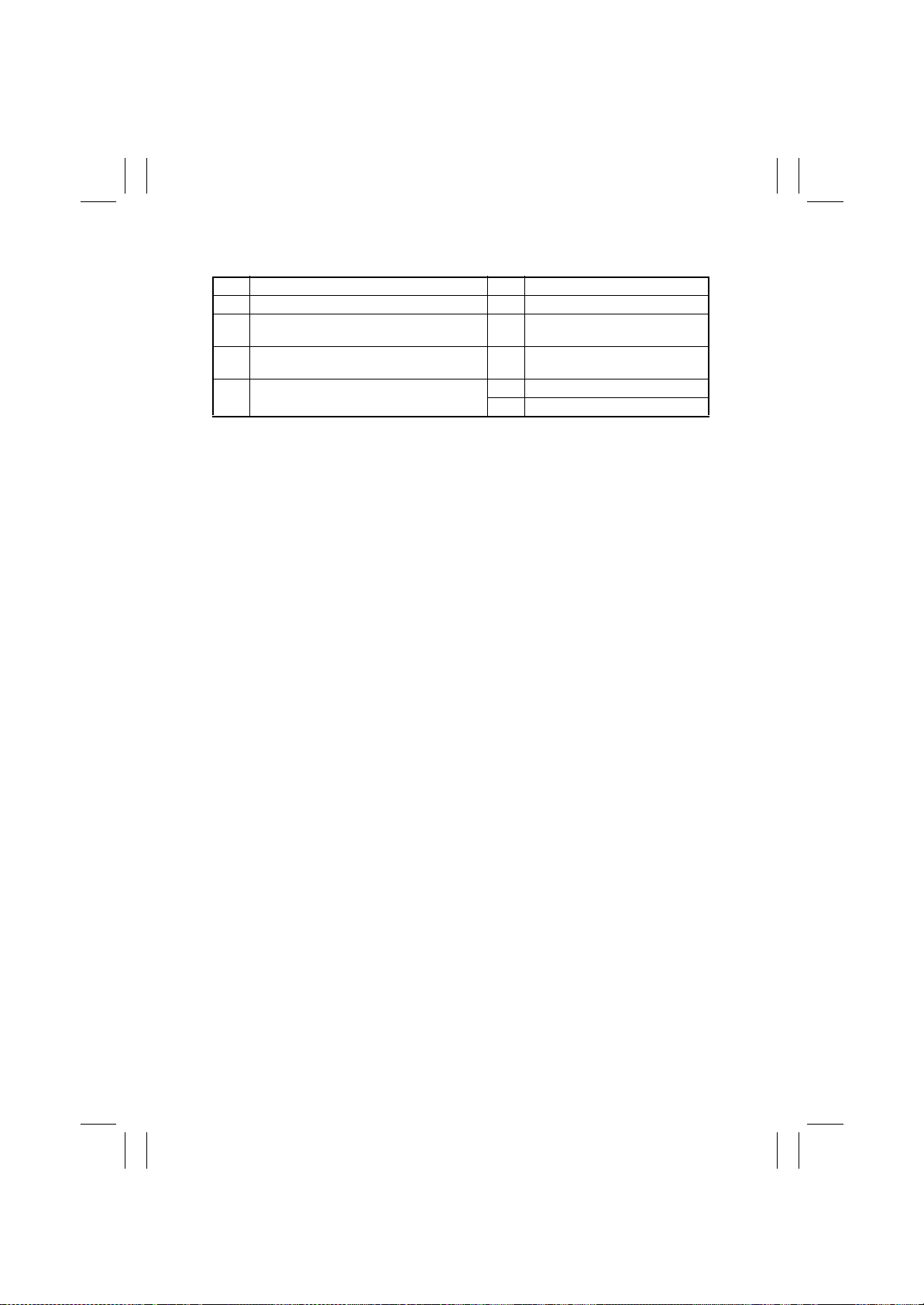
(6) C0B4C Booklet Exit Motor malfunctions
Step Check Item Result Action
Does the sensor operate normally?
1
Is the wiring between the Control Board and
2
the Booklet Exit Motor correct?
When the Booklet Exit Belt is turned manually,
3
does the belt turn smoothly?
Is the malfunction fixed when the Booklet Exit
4
Motor is replaced?
Replace the sensor.
NO
Correct the wiring.
NO
Adjust the mechanism.
NO
End.
YES
Replace the Control Board.
NO
T-10
Page 67
FrameMaker Ver.5.5E(PC) FS-231 OPTION For 8020/8031
02.08.23
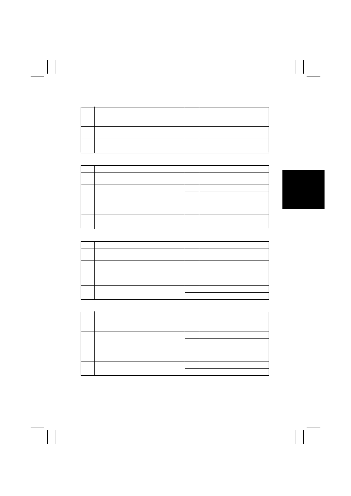
(7) C0B55 Stapler/Folding Motor malfunctions
• Wiring
Step Check Item Result Action
Is the wiring between the Control Boar d and
1
the Stapler/Folding Motor correct?
When turned, is the Staple Jam Release Dial
2
caught mechanically?
Is the malfunction fixed when the Stapler/Fold-
3
ing Motor is replaced?
Correct the wiring.
NO
Adjust the mechanism.
YES
End.
YES
Replace the Control Board.
NO
• Stapler/Crease Clock Sensor (Stapler Section)
Step Check Item Result Action
Does the Stapler/Crease Clock Sensor operate
1
normally?
Does the Stapler/Folding Motor operate with
the preset timing?
2
Is the malfunction fixed when the Stapler/Fold-
3
ing Motor is replaced?
Replace the sensor.
NO
Replace the Control Board.
YES
Check the Stapler Section Drive
Mechanism. If any malfunctions,
NO
repair it. If no malfunctions, go to
Step 3.
End.
YES
Replace the Control Board.
NO
• Home Position Sensor
Step Check Item Result Action
Does the Crease Home Position Sensor oper-
1
ate normally?
Is the wiring between the Control Boar d and
2
the Stapler/Folding Motor correct?
When turned, is the Folding Jam Release Dial
3
caught mechanically?
Is the malfunction fixed when the Stapler/ Fold-
4
ing Motor is fixed?
Replace the sensor.
NO
Correct the wiring.
NO
Adjust the mechanism.
YES
End.
YES
Replace the Control Board.
NO
• Stapler/Crease Clock Sensor (Saddle Section)
Step Check Item Result Action
Does the Stapler/Crease Clock Sensor operate
1
normally?
Does the Stapler/Folding Motor operate with
the preset timing?
2
Is the malfunction fixed the Stapler/Folding
3
Motor is replaced?
Replace the sensor.
NO
Replace the Control Board.
YES
Check the Saddle Section Drive
mechanism. If any malfunctions,
NO
repair it. If no malfunctions, go to
Step 3.
Completed.
YES
Replace the Control Board.
NO
T-11
Page 68
FrameMaker Ver.5.5E(PC) FS-231 OPTION For 8020/8031
02.08.23
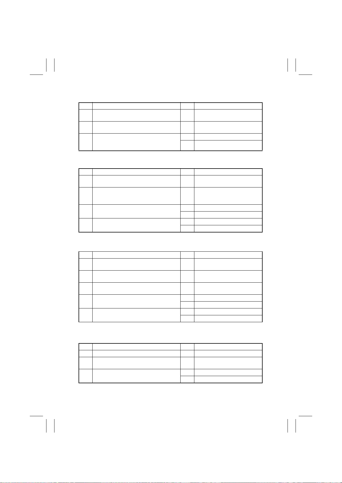
(8) C0B75 Punch Control Board malfunctions
Step Check Item Result Action
Is the malfunction fixed when POWER ON is
1
renewed?
Is the wiring between the Control Board and
2
the Punch Unit correct?
Measure the voltage between CN14-5 (+) and
CN14-3 (-) of the Control Board. Is the voltage
3
24VDC?
End.
YES
Correct the wiring.
NO
Replace the Punch Unit Board.
YES
Replace the Control Board.
NO
(9) C0B76 Punch Side Registration Motor malfunctions
Step Check Item Result Action
Does the Side R eg is t r a ti on Ho m e Position Se n-
1
sor operate normally?
Is the wiring between the Punch Unit Board
and the Side Registration Home Position Sen-
2
sor correct?
Does the Side Registration Mechanism operate
3
normally?
Is the malfunction fixed when the Punch Unit
4
Board is replaced?
Replace the sensor.
NO
Correct the wiring.
NO
Replace the Side Registration Motor.
YES
Adjust the Side Registration Mechanism.
NO
End.
YES
Replace the Control Board.
NO
(10) C0B77 Punch Motor malfunctions
Step Check Item Result Action
Does the Punch Home Position Sensor operate
1
normally?
Does the Punch Motor Clock Sensor operate
2
normally?
Is the wiring between the Punch Unit Board
3
and each sensor correct?
Is there any malfunction in the Punch Mecha-
4
nism?
Is the malfunction fixed when the Punch Unit
5
Board is replaced?
Replace the sensor.
NO
Replace the sensor.
NO
Correct the wiring.
NO
Repair the Punch mechanism.
YES
Replace the Punch Motor.
NO
End.
YES
Replace the Control Board.
NO
(11) C0B79 Punch Sensor malfunctions
• Side Registration Sensor
Step Check Item Result Action
Does the Side Registration Sensor operate normally?
1
Is the wiring between the Punch Unit Board
2
and the Side Registration Sensor correct?
Is the malfunction fixed when the Punch Unit
3
Board is replaced?
Replace the sensor.
NO
Correct the wiring.
NO
End.
YES
Replace the Control Board.
NO
T-12
Page 69
FrameMaker Ver.5.5E(PC) FS-231 OPTION For 8020/8031
02.08.23
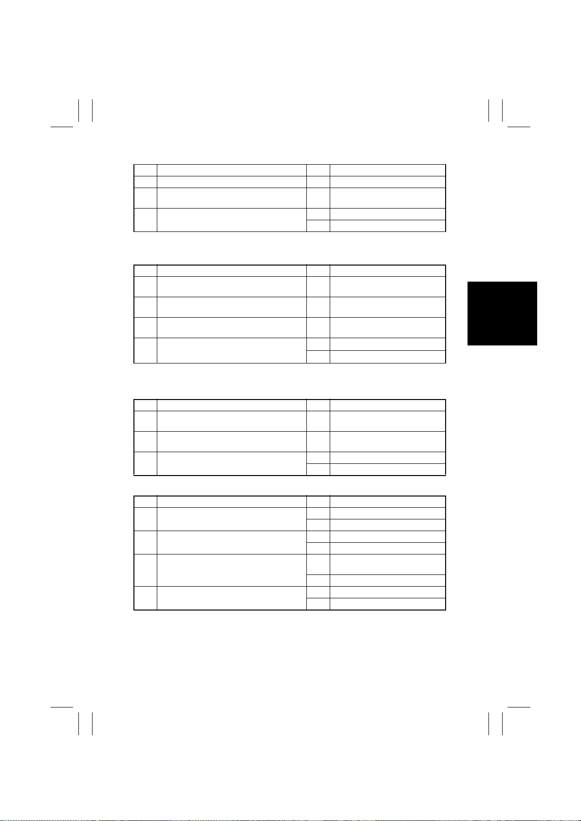
• Wastes Full Sensor
Step Check Item Result Action
Does the Wastes Full Sensor operate normally?
1
Is the wiring between the Punch Unit PCB and
2
the Wastes Full Sensor correct?
Is the malfunction fixed when the Punch Unit
3
Board is replaced?
Replace the sensor.
NO
Correct the wiring.
NO
End.
YES
Replace the Control Board.
NO
(12) C0B81 Shift Mechanism malfunctions
Step Check Item Result Action
Does the Paper Surface Sensor operate nor-
1
mally?
Does the Tray Elevator Mechanism operate
2
normally?
Is 24VDC supplied from the Control Board to
3
the Shift Motor with the tray drive timing?
Is the wiring between the Control Board and
4
the Shift Motor correct?
NO
Replace the sensor.
NO
Repair the mechanism.
NO
Replace the Control Board.
YES
Replace the Shift Motor.
NO
Correct the wiring.
(13) C0BA0 Elevate Mechanism malfunctions
• Upper Limit Sensor
Step Check Item Result Action
Has the tray reached the Upper limit Sensor
1
position?
Does the Upper Limit Sensor operate nor-
2
mally?
Is the wiring between the Control Board and
3
the Raised Position Sensor correct?
Lower the Tr ay.
YES
Replace the sensor.
NO
Replace the Control Board.
YES
Replace or correct the wiring.
NO
• Control Board
Step Check Item Result Action
Is the tray moving up?
1
Is 24VDC supplied from the Control Board to
2
the Motor with the Tray up/down timing?
Is there any malfunction in the Tray up/down
Mechanism?
3
Does the Shift Motor Clock Sensor operate nor-
4
mally?
Go to Step 4.
YES
Go to Step 2.
NO
Go to Step 3.
YES
Replace the Control Board.
NO
Repair the Tray up/down Mecha-
YES
nism.
Replace the Tray up/down Motor.
NO
Replace the Control Board.
YES
Replace the Sensor.
NO
T-13
Page 70
FrameMaker Ver.5.5E(PC) FS-231 OPTION For 8020/8031
02.08.23
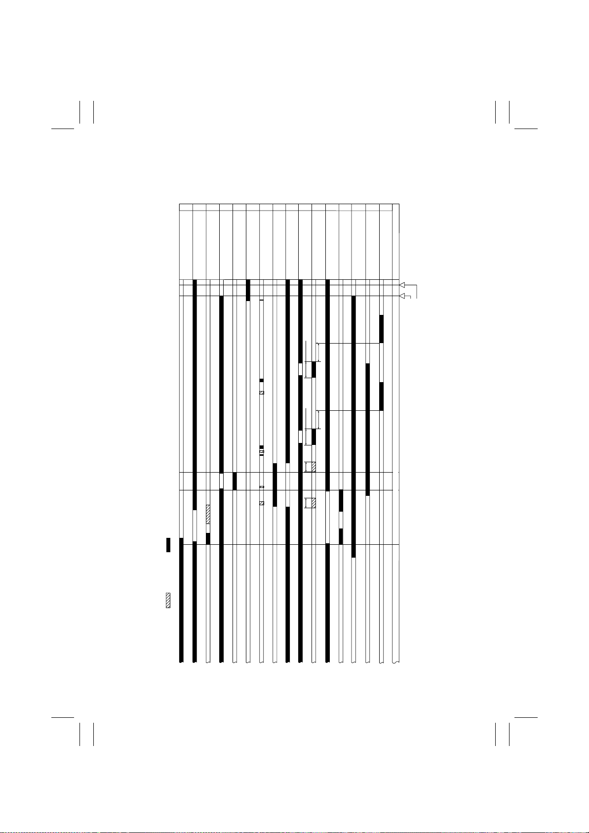
4. Overall Timing Chart
4-1. Finisher Section
Staple A-4 size paper, Two originals, Rear binding at a point.
Exit Home
Position Sensor (PI9)
Exit Tray Sensor (PI8)
141615
Shift Motor (M6)
Staple Home
Position Sensor (PI19)
121113
10
9
Staple / Folding Motor (M7)
Staple Safey Switch (MS3)
Front Aligning Motor (M4)
Front Aligning Plate Home
Position Sensor (PI4)
6
8
7
Paddle Motor (M2)
Paddle Home
Position Sensor (PI2)
Swing Guide Home
Position Sensor (PI3)
Paddle Rotation
630msec
5
Exit Belt Home
Position Sensor (PI7)
4
3
Transport Motor (M1)
Exit Motor (M3)
2
1
Entrance Sensor (PI1)
Finisher Tray Sensor (PI6)
Operation
Operation Start Signal
Exit Signal From Connected Units
: Motor Rotation : Motor Reverse Rotation
Paddle Rotation
360msec
Lower
Staple
Upper
Booklet Exit
T-14
Page 71
FrameMaker Ver.5.5E(PC) FS-231 OPTION For 8020/8031
02.08.23
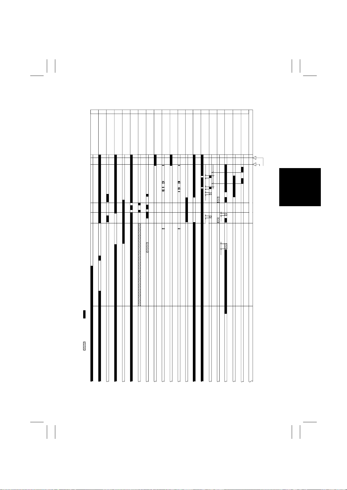
4-2. Saddle Section
Booklet Creation LTR Size Paper, Two Original Feeds, One Copies.
17
18
19
20
Sensor (PI11)
Suddle Tray Sensor (PI13)
Folding Roller Home
Position Sensor (PI12)
Saddle Clutch (CL1)
Folding Home Position
Folding Position Sensor (PI10)
Staple Home
Position Sensor (PI19)
121113
141615
Staple / Folding Motor (M7)
Rear Ailgning Plate Home
Position Sensor (PI5)
Slide Motor (M8)
Rear Aligning Motor (M5)
10
9
8
Staple Safey Switch (MS3)
Front Aligning Motor (M4)
Front Aligning Plate Home
Position Sensor (PI4)
5
6
7
Paddle Motor (M2)
Paddle Home
Position Sensor (PI2)
Swing Guide Home
Position Sensor (PI3)
Paddle Rotation
4
Exit Motor (M3)
360msec
2
1
3
Entrance Sensor (PI1)
Finisher Tray Sensor (PI6)
Transport Motor (M1)
Operation
Operation Start Signal
Exit Signal From Connected Units
: Motor Rotation : Motor Reverse Rotation
Lower
Upper
Staple (Rear,Front)
Lower
Upper
Folding, Exit
T-15
Page 72
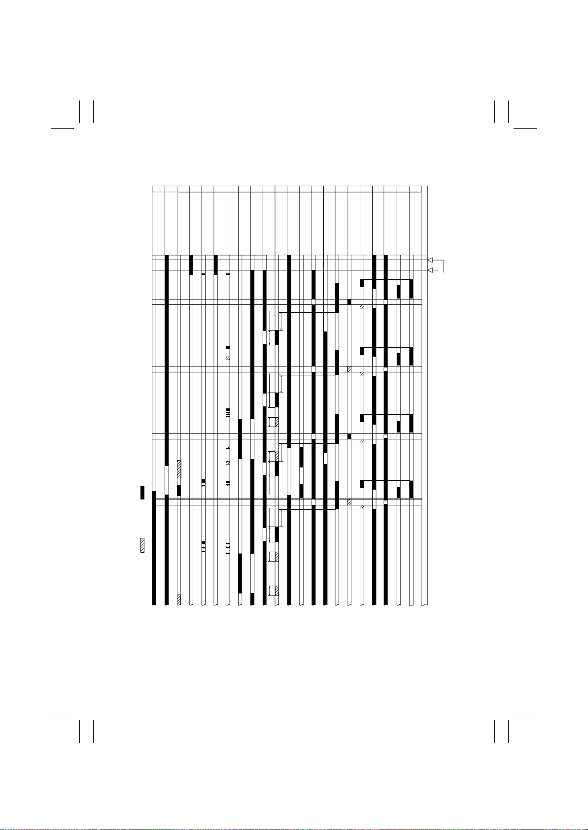
FrameMaker Ver.5.5E(PC) FS-231 OPTION For 8020/8031
02.08.23
4-3. Punch Section (Option)
Punch A-4 Size Paper, Two Original Feeds, Two Copies.
22
21
Exit Tray Sensor (PI8)
Exit Home Position Sensor (PI9)
18
20
19
Rear Ailgning Plate
Home Position Sensor (PI5)
Home Position Sensor (PI4)
Rear Aligning Plate Motor (M5)
Shift Motor (M6)
17
Front Aligning Motor (M4)
Front Aligning Plate
121113
141615
Swing Guide Home
Position Sensor (PI3)
Paddle Motor (M2)
Paddle Home
Position Sensor (PI2)
Staple Safey Switch (MS3)
10
9
Transport Moto r(M1)
Exit Motor (M3)
Exit Belt Home
Position Sensor (PI7)
8
7
Entrance Sensor (PI1)
Finisher Tray Sensor (PI6)
5
6
4
Punch Motor (M1P)
Registration Motor (M2P)
Registration Home
Position Sensor (PI2P)
2
3
Registration Sensor
(LED1 to 4,PT1 to 4)
Punch Home Position
Sensor (PI1P)
1
Tailing Edge Sensor (LED5,PT5)
Operation
Operation Start Signal
Exit Signal Connected Units
: Motor Rotation : Motor Reverse Rotation
Paddle Rotation
630msec
360msec
Paddle Rotation
Lower Upper
630msec
Paddle Rotation
Paddle Rotation
360msec
Lower Upper
Punch
Punch Punch
PunchBooklet Exit
T-16
 Loading...