

Page 1

FrameMaker Ver.5.5(PC) FS-135 OPTION FOR 8020/8031
02.08.23
FS-135
SERVICE MANUAL
Page 2

FrameMaker Ver.5.5(PC) FS-135 OPTION FOR 8020/8031
02.08.23
Blank page
Page 3

FrameMaker Ver.5.5(PC) FS-135 OPTION FOR 8020/8031
02.08.23
CONTENTS
GENERAL
1. SPECIFICATIONS ........................................................................................... G-1
2. DRIVE SYSTEM ..............................................................................................G-3
3. ELECTRICAL COMPONENTS LAYOUT ........................................................G-4
SWITCHES ON PWB, TEST MODE
1. SWITCHES ON PWB ......................................................................................S-1
2. TEST MODE .................................... ............................ ....................................S-2
2-1. Test Mode Setting Procedure ..................................................................S-2
2-2. Test Mode Operations .............................................................................S-2
2-3. Operation in Each Test Mode Operation .................................................S-3
(1) 1st Tray Exit .....................................................................................S-3
(2) Elevator Tray Exit ..................... ...................................................... .S-3
(3) Finisher Tray Exit .............................................................................S-3
(4) 3rd Tray Exit ............ ........................... ........................... ..................S-4
(5) Shifting Operation ............................... ........................... ..................S-4
(6) Aligning Plate Operation ..................................................................S-4
(7) Stapling Unit CD Movement ............................................................S-5
(8) Exit Roller/Rolls Spacing .................... ............... ............... .............. .S-5
(9) Storage Roller/Rolls Spacing ...........................................................S-5
(10) Ele v a to r Tray Operation ................... ........................... ............... .....S-6
(11) Se n sor Test ............... ........................... ............................ ...............S-6
DIS/REASSEMBLY, ADJUSTMENT
1. DISASSEMBLY AND REASSEMBLY ............................. ........................... .....D-1
1-1. Maintenance Schedule ............................................................................D-1
1-2. Removal of the Exterior Parts .................................................................. D-1
1-3. Removal of the Stapling Unit ...................................................................D-2
2. ADJUSTMENTS ..............................................................................................D-3
2-1. Adjustment of the Solenoids ....................................................................D-3
(1) Adjustment of the Upper/Lower Entrance Switching Solenoid
(SL1) .............................................................................................D-3
(2) Adjustment of the 1st Tray Entrance Selecting Solenoid (SL2) .......D-3
2-2. Timing Belt Tension Adjustment ..............................................................D-4
(1) Adjustment of the Upper Entrance Motor (M4) Timing Belt .............D-4
(2) Adjustment of the Lower Entrance Motor (M2) Timing Belt .............D-4
(3) Adjustment of the Exit Motor (M3) Timing Belt ..................... ...........D-4
2-3. Adjustment of the Elevator Tray Upper Limit Sensor ...............................D-5
TROUBLESHOOTING
1. SENSOR CHECK .................. ........................... ........................... ....................T-1
1-1. Sensor Check Scre en ......................... ........................... ..........................T-1
1-2. Sensor Check List .......................................................... ..........................T-2
1-3. Sensor Check Proc edu r e ......................................... ........................... .....T-4
2. MISFEED DETECTION AND TROUBLESHOOTING PROCEDURES ...........T-5
2-1. Misfeed Detecting Sensor Layout ............................................................T-5
i
Page 4

FrameMaker Ver.5.5(PC) FS-135 OPTION FOR 8020/8031
02.08.23
2-2. Misfeed Detection ....................................................................................T-6
2-3. Misfeed Troubleshooting Procedures ......................................................T-7
(1) Transport misfeed ............................................................................T-7
(2) Misfeed at the 1st Tray exit .............................................................T-7
(3) Misfeed at the 3rd Tray exit (FT-331) ..............................................T-8
(4) Misfeed at the Elevator Tray exit .....................................................T-8
(5) Paper stack exit misfeed .................................................................T-8
(6) Staple misfeed ................................................................................. T-9
3. MALFUNCTION DETECTION AND TROUBLESHOOTING PROCEDURES .T-10
3-1. Malfunction Detection ..............................................................................T-10
3-2. Malfunction Troubleshooting Procedures ................................................ T-1 1
(1) C0B20 .............................................................................................T-11
(2) C0B30 .............................................................................................T-11
(3) C0B48 .............................................................................................T-11
(4) C0B4A ............................................................................................. T-11
(5) C0B50 .............................................................................................T-12
(6) C0B80 .............................................................................................T-12
(7) C0BA0 .............................................................................................T-12
ii
Page 5

FrameMaker Ver.5.5(PC) FS-135 OPTION FOR 8020/8031
02.08.23
GENERAL
Page 6

FrameMaker Ver.5.5(PC) FS-135 OPTION FOR 8020/8031
02.08.23
Blank page
Page 7
FrameMaker Ver.5.5(PC) FS-135 OPTION FOR 8020/8031
02.08.23
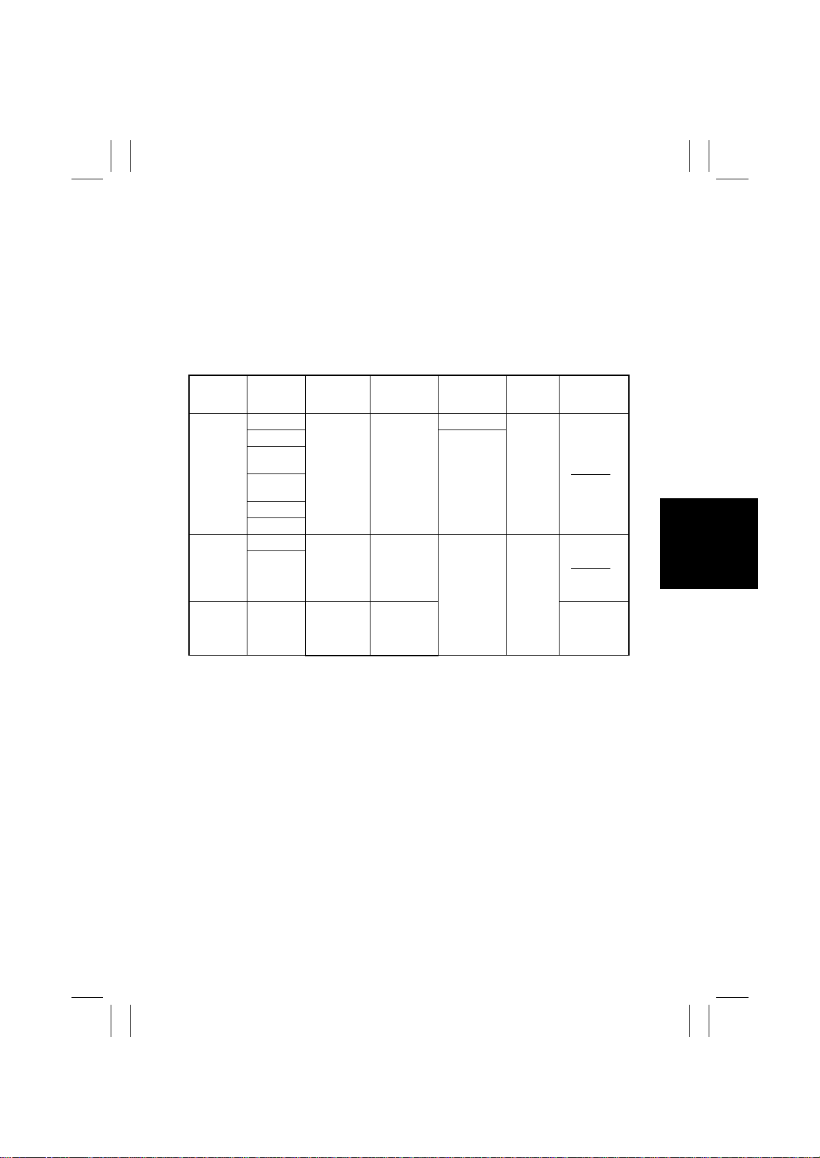
1. SPECIFICATIONS
Type : Single Staple Finisher
Installation : Freestanding
Modes : Non-Sort Copier
Non-Sort, Sort, Group
Sort Staple, Group Staple PC Print
Copy Medium
Mode Paper Type Paper Size Paper Weight Capacity
250 sheets
2
20 sheets
Non-Sort
Plain paper
Thick paper
Transparen-
cies
Translucent
paper
Envelopes
A3W to A6L
18”
12-1/4
×
to
8-1/2”
5-1/2
×
60 to 256 g/m
16 to 68-1/4 lb
Output
st
1
Tray
Tray
Max. No. of
Sheets to be
Stapled
Plain paper A3W to A4L/
Sort, Group
Sort Staple,
Group
Staple
✽
: 20 sheets if originals of high ID (Color Wise 3) is used.
Thick paper
Plain paper
A4C
12-1/4 ×18”
to
8-1/2 × 11”
A3 to A4L/
A4C
11 × 17” to
8-1/2 × 11”
60 to 209 g/m
16 to 55-1/2 lb
60to 90 g/m
16 to 24 lb
2
1,000 sheets
(A4L. 8-1/2 or
smaller);
500 sheets
(B4L . 8-1/2 or
2
larger)
: 15 sheets when using Color Copy 90 paper.
✽
: 20 sheets when using Radiant White paper.
Registration : Center
No. of Holes : 2, 3 or 4 holes
Power Requirements : DC 24 V (supplied from copier)
DC 5 V (generated by Finisher)
Power Consumption : 63 W
Dimensions : Width: 538 mm, 21-1/4”
Depth: 637mm, 25-1/16”
Height: 978 mm, 38-1/2”
Mass : 35.5 kg, 78-1/4 lb
Environmental Require-
: Same as copier
ments
Supplies : Staple Cartridge
Elevator
Tray
30 sheets
(60 to 80 g/m2,
16 to 21 lb)
✽
G-1
Page 8
FrameMaker Ver.5.5(PC) FS-135 OPTION FOR 8020/8031
02.08.23
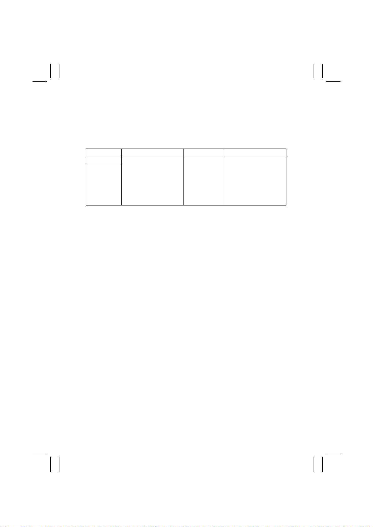
<FT-331>
Name :
rd
3
Tray
Installation : Fixed to Finisher
Modes : Non-Sort (in the fax or printer output mode)
Copy Medium
Paper Type Paper Size Paper Weight Capacity
Plain paper
100 sheets:
A4C, 8-1/2 × 11”
2
Recycled
paper
A3L to AaC/A4L
11 × 17” to 5-1/2 × 8-1/2”
60 to 90 g/m
16 lb to 24 lb
(80 g/m
2
50 sheets:
except A4C, 8-1/2 × 11”
(80 g/m
, 20 lb)
2
, 20 lb)
(Height: up to 28 mm, 1 lb)
Registration : Center
Power Requirements : DC 5 V, DC 24 V (supplied from Finisher)
Dimensions : Width: 341 mm, 13-1/2
Depth: 527 mm, 20-3/4
Height: 149 mm, 5-3/4
Mass : 1.75 kg, 3-3/4 lb
Environmental Require-
: Same as copier
ments
G-2
Page 9
FrameMaker Ver.5.5(PC) FS-135 OPTION FOR 8020/8031
02.08.23
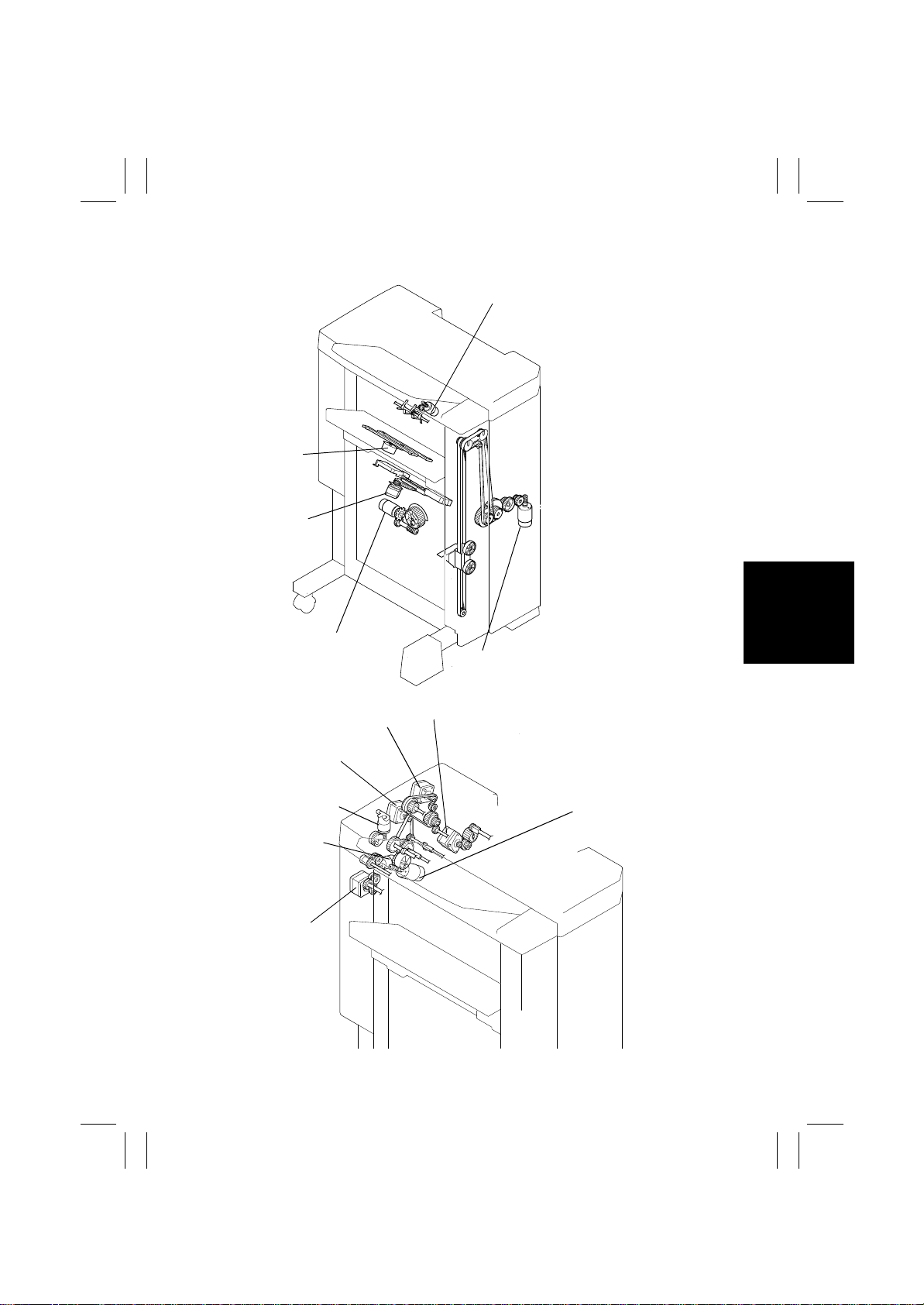
2. DRIVE SYSTEM
Lower Paddle Motor (M9)
CD Aligning
Motor (M5)
Stapling Unit
Moving Motor (M6)
Shift Motor (M8)
Upper Entrance Motor (M4)
Lower Entrance Motor (M2)
Exit Roller/Rolls
Spacing Motor (M13)
Upper Paddle
Motor (M15)
Exit Motor (M3)
Elevator Motor (M7)
Entrance Motor (M1)
G-3
4643M003AC
Storage Roller/Rolls
Spacing Motor (M12)
4643M004AA
Page 10
FrameMaker Ver.5.5(PC) FS-135 OPTION FOR 8020/8031
02.08.23
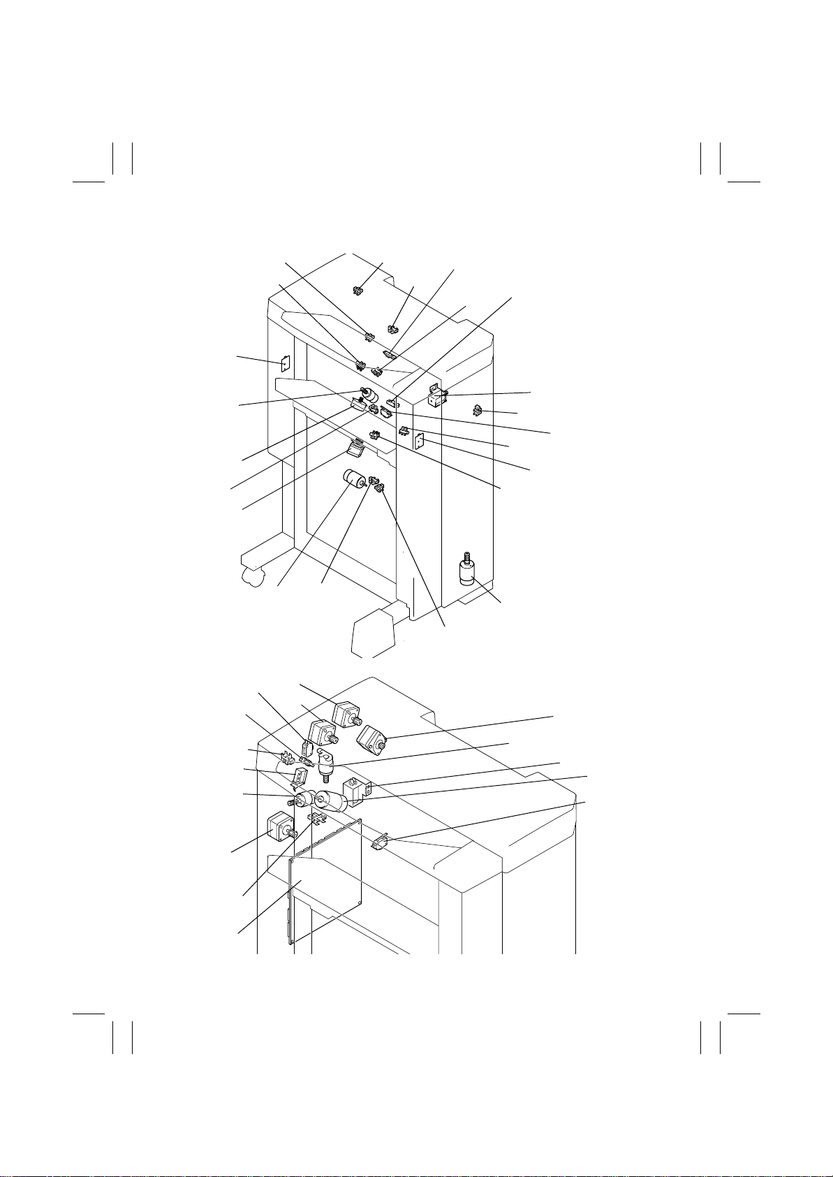
3. ELECTRICAL COMPONENTS LAYOUT
PWB-D
M9
PC8
M5
M6
PC6
PC4
M8
PC11
PC18
PC1
PC2
PC10
PC3
PC5
SL2
PC17
S2
PC9
PWB-C
PC14
M7
4643M005AC
PC13
SL3
M15
M3
PC12
PWB-A
PC7
S3
M4
M2
M1
M13
SL1
M12
S1
4643M006AA
G-4
Page 11
FrameMaker Ver.5.5(PC) FS-135 OPTION FOR 8020/8031
02.08.23
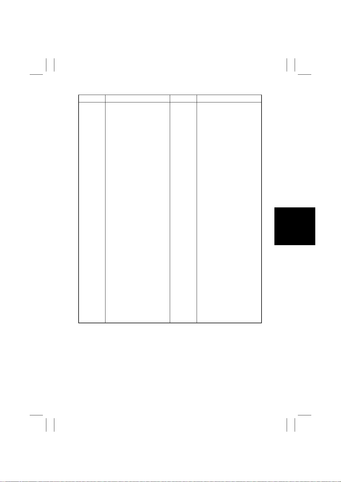
Symbol Name Symbol Name
PWB-A Control Board PC1
PWB-C Elevator Tray Upper Limit Sen-
sor LED
PWB-D Elevator Tray Upper Limit Sen-
sor PQ
PC2 Lower Entrance Sensor
PC3 Storage Sensor
PC4 Upper Entrance Sensor
PC5 Finisher Tray Paper Detecting
st
Tray Exit Sensor
1
SensorM1 Entrance Motor
M2 Lower Entrance Motor PC6
st
Tray Full Detecting Sensor
1
M3 Exit Motor PC7 Elevator Tray Full Detecting
M4 Upper Entrance Motor
Sensor
M5 CD Aligning Motor PC8 Elevator Tray Paper Detecting
M6 Stapling Unit Moving Motor
Sensor
M7 Elevator Motor PC9 CD Aligning Home Position
M8 Shift Motor
Sensor
M9 Lower Paddle Motor PC10 Shift Home Position Sensor
M12 Storage Roller/Rolls Spacing
Motor
PC11 Shift Motor Pulse Sensor
PC12 Storage Roller Home Position
SensorM13 Exit Roller/Rolls Spacing
Motor
M15 Upper Paddle Motor PC13 Exit Roller Home Position Sen-
sor
SL1 Upper/Lower Entrance Switch-
ing Solenoid
SL2
st
Tray Entrance Selecting
1
Solenoid
SL3 Upper Paddle Solenoid PC20
SL4
rd
Tray Entrance Selecting
3
Solenoid
PC14 Staple Home Position Sensor
PC17 Front Door Detecting Sensor
PC18 Upper Cover Detecting Sensor
PC19
PC21
rd
Tray Exit Sensor
3
rd
Tray Full Detecting Sensor
3
3rd Tray Open/Close Sensor
S1 Set Switch
S2 Elevator Tray Upper Limit
Switch
G-5
Page 12

FrameMaker Ver.5.5(PC) FS-135 OPTION FOR 8020/8031
02.08.23
Blank page
G-6
Page 13

FrameMaker Ver.5.5(PC) FS-135 OPTION FOR 8020/8031
02.08.23
SWITCHES ON PWB,
TEST MODE
Page 14

FrameMaker Ver.5.5(PC) FS-135 OPTION FOR 8020/8031
02.08.23
Blank page
Page 15
FrameMaker Ver.5.5(PC) FS-135 OPTION FOR 8020/8031
02.08.23
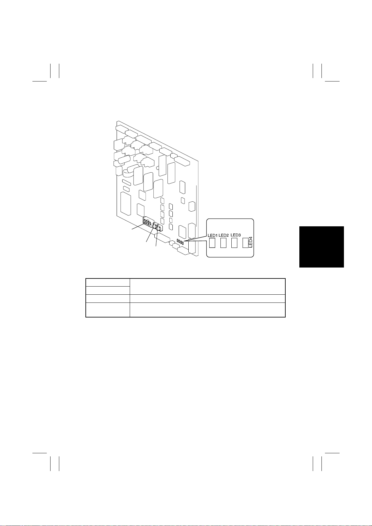
1. SWITCHES ON PWB
S3
S2
S1
S1
S2
S3 DIP switch used to set the Test Mode operation.
LED1~4
Used to run the Test Mode operation.
Turn ON or OFF, or blink to indicate a specific condition during Test
Mode operations.
4643S001AB
S-1
Page 16
FrameMaker Ver.5.5(PC) FS-135 OPTION FOR 8020/8031
02.08.23
2. TEST MODE
2-1. Test Mode Setting Procedure
<Setting Procedure>
1. Turn OFF the Power Switch of the copier.
2. Flip keys of the DIP switch into the ON or OFF position as necessary. (See Table
below.)
3. Turn ON the Power Switch of the copier.
4. This sets the Finisher into the corresponding Test Mode operation.
<Resetting Procedure>
• Flip all keys of the DIP switch to their respective initial positions and turn OFF, then ON,
the Power Switch of the copier.
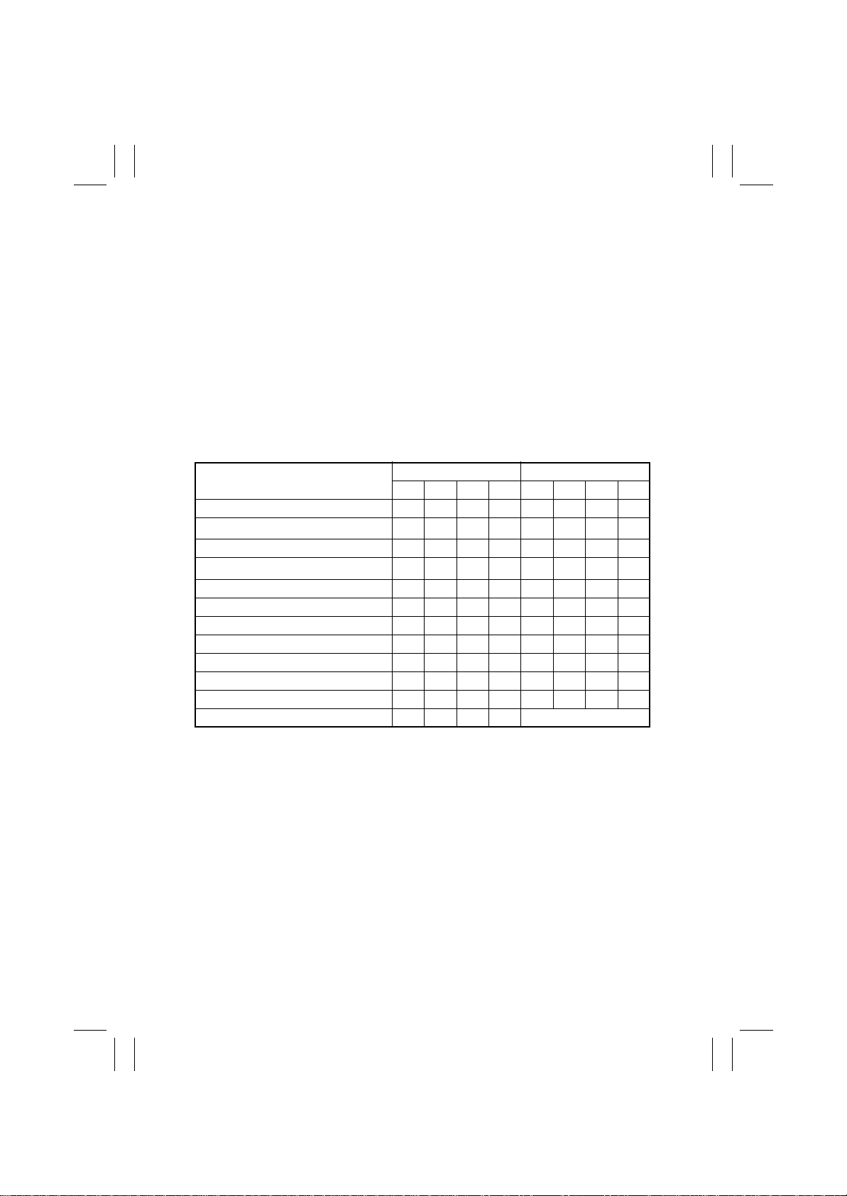
2-2. Test Mode Operations
Test Mode Operation
Online
st
Tray exit
1
Elevator Tray exit ON
rd
3
Tray exit
Finisher Tray exit ON ON
Shifting operation ON ON
Aligning Plate operation ON ON
Stapling Unit CD movement ON ON ON
Exit Roller/Rolls spacing ON
Storage Roller/Rolls spacing ON ON
Elevator Tray operation ON ON
Sensor test ON ON ON Indicates sensor state
●
✽
Whenever the Control Board (PWB-A) is to be replaced, take note of the initial positions
of all keys of the DIP switch. After the replacement procedure has been completed, be
sure to flip all keys of the DIP switch on the new Control Board (PWB-A) to their respective initial positions.
DIP Switch (S3) LED
12341234
❍❍❍●
ON
ON
●❍❍❍
❍●❍❍
❍❍●❍
●●❍❍
●❍●❍
❍●●❍
●●●❍
❍❍❍●
●❍❍●
❍●❍●
: Blinking ❍: OFF
S-2
Page 17
FrameMaker Ver.5.5(PC) FS-135 OPTION FOR 8020/8031
02.08.23
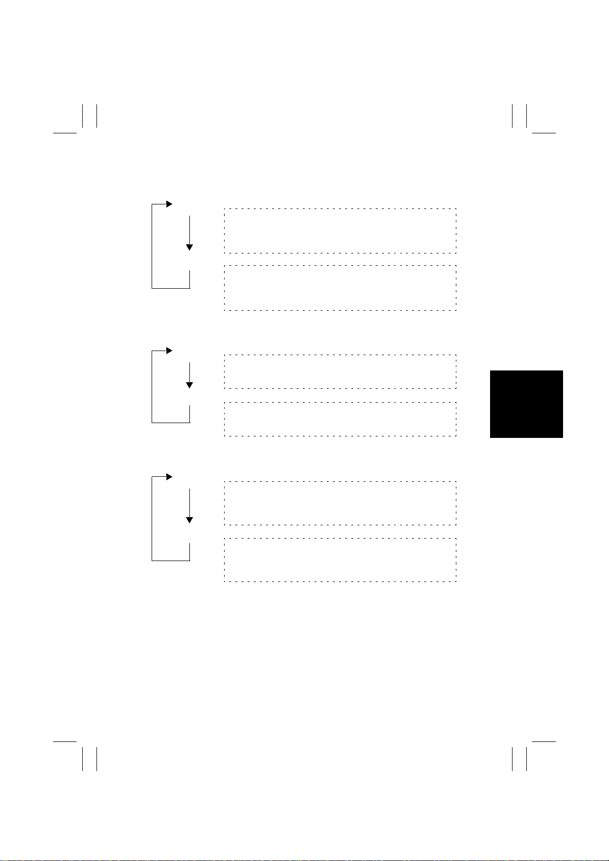
2-3. Operation in Each Test Mode Operation
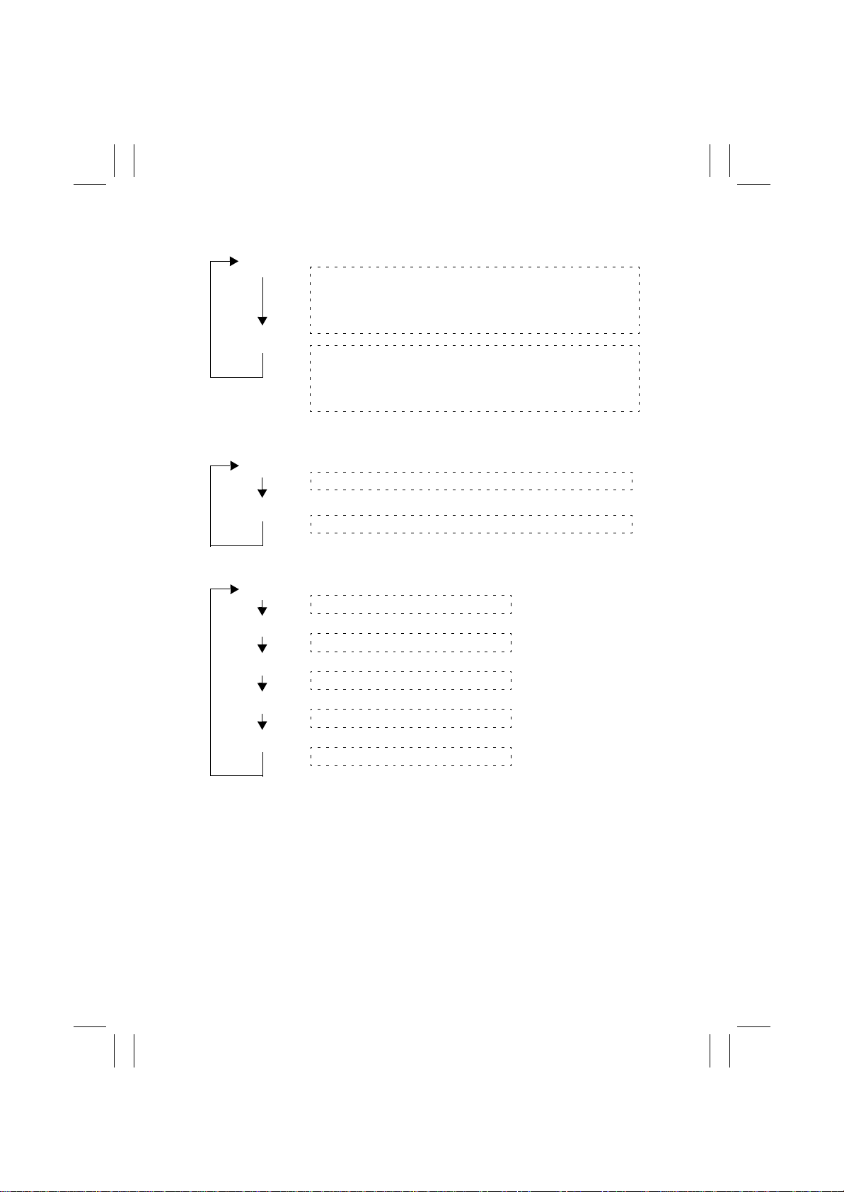
(1) 1st Tray Exit
S1: ON
S2: ON
(2) Elevator Tray Exit
S1: ON
S2: OFF
(3) Finisher Tray Exit
S1: ON
S2: OFF
Motors and solenoids: Energized
[Entrance Motor (M1), Upper Entrance Motor (M4), Upper/
Lower Entrance Switching Solenoid (SL1), 1
Selecting Solenoid (SL2)]
Motors and solenoids: Deenergized
[Entrance Motor (M1), Upper Entrance Motor (M4), Upper/
Lower Entrance Switching Solenoid (SL1), 1
Selecting Solenoid (SL2)]
Motors: Energized
[Entrance Motor (M1), Lower Entrance Motor (M2), Exit Motor
(M3)]
Motors: Deenergized
[Entrance Motor (M1), Upper Entrance Motor (M4), Lower
Entrance Motor (M2), Exit Motor (M3)]
Motors and solenoids: Energized
[Entrance Motor (M1), Upper Entrance Motor (M4), Lower
Entrance Motor (M2), Exit Motor (M3), Upper/Lower Entrance
Switching Solenoid (SL1)]
Motors and solenoids: Deenergized
[Entrance Motor (M1), Upper Entrance Motor (M4), Lower
Entrance Motor (M2), Exit Motor (M3), Upper/Lower Entrance
Switching Solenoid (SL1)]
st
Tray Entrance
st
Tray Entrance
S-3
Page 18
FrameMaker Ver.5.5(PC) FS-135 OPTION FOR 8020/8031
02.08.23
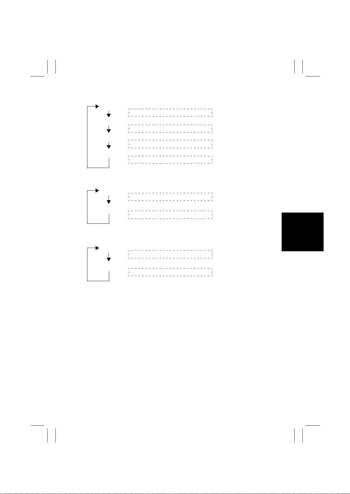
(4) 3rd Tray Exit
S1: ON
Motors and solenoids: Energized
[Entrance Motor (M1), Upper Entrance Motor (M4), Upper/Lower
Entrance Switching Solenoid (SL1), 1
Solenoid (SL2), 3
rd
Tray Entrance Selecting Solenoid (SL4)]
S2: ON
Motors and solenoids: Deenergized
[Entrance Motor (M1), Upper Entrance Motor (M4), Upper/Lower
Entrance Switching Solenoid (SL1), 1
Solenoid (SL2), 3
rd
Tray Entrance Selecting Solenoid (SL4)]
(5) Shifting Operation
st
Tray Entrance Selecting
st
Tray Entrance Selecting
S1: ON
The Elevator Tray shifts to the front.
S2: ON
The Elevator Tray shifts to the rear.
(6) Aligning Plate Operation
S1: ON
At the home position
S1: ON
At a position to align A4C paper
S1: ON
At a position to align Letter C paper
S1: ON
At a position to align A4L paper
S1: ON
At a position to align Letter L paper
S-4
Page 19
FrameMaker Ver.5.5(PC) FS-135 OPTION FOR 8020/8031
02.08.23
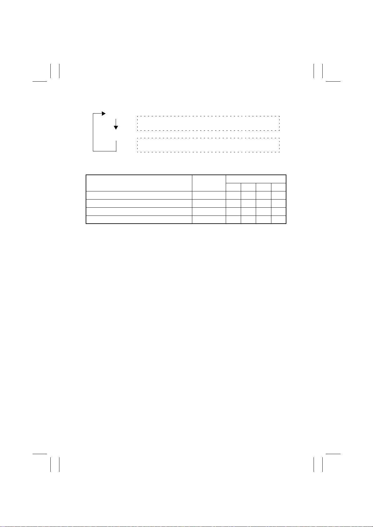
(7) Stapling Unit CD Movement
S1: ON
S1: ON
S1: ON
S1: ON
(8) Exit Roller/Rolls Spacing
S1: ON
S2: ON
(9) Storage Roller/Rolls Spacing
S1: ON
S2: ON
At home position
At a position for A4C corner stapling
At home position
At a position for A4L corner stapling
Pressed
Separated
Pressed
Separated
S-5
Page 20
FrameMaker Ver.5.5(PC) FS-135 OPTION FOR 8020/8031
02.08.23
(10) Elevator Tray Operation
S1: ON
S2: ON
(11) Sensor Test
Elevator Tray Upper Limit Sensor PQ (PWB-D) Unblock ed
Storage Sensor (PC3) Blocked
Lower Entrance Sensor (PC2) Blocked
Upper Entrance Sensor (PC4) Blocked
●
: ON ❍: OFF
Goes up until the Elevator Tray Upper Limit Sensor PQ
(PWB-D) is blocked.
Goes down until the Elevator Tray Upper Limit Sensor PQ
(PWB-D) is unblocked.
Sensor State
LED
1234
❍❍❍●
❍❍●❍
❍●❍❍
●❍❍❍
S-6
Page 21

FrameMaker Ver.5.5(PC) FS-135 OPTION FOR 8020/8031
02.08.23
DIS/REASSEMBLY,
ADJUSTMENT
Page 22

FrameMaker Ver.5.5(PC) FS-135 OPTION FOR 8020/8031
02.08.23
Blank page
Page 23
FrameMaker Ver.5.5(PC) FS-135 OPTION FOR 8020/8031
02.08.23
1. DISASSEMBLY AND REASSEMBLY
1-1. Maintenance Schedule
• To ensure good copies and an extended service life of the Finisher, it is recommended
that the maintenance jobs described in this schedule be carried out.
PM Parts
Rollers/Rolls 300 Alcohol, water Transport failure
Paddles 300 Alcohol, water Transport failure
NOTES
1. This information is subject to change without notice.
2. K = 1,000 copies
3. Upon PM service, check the Punch Trash Box and dump trash as may be necessary.
Cleaning
(K)
Tools Used for
Cleaning
Possible Malfunction Life Counter
Sorter/Finisher
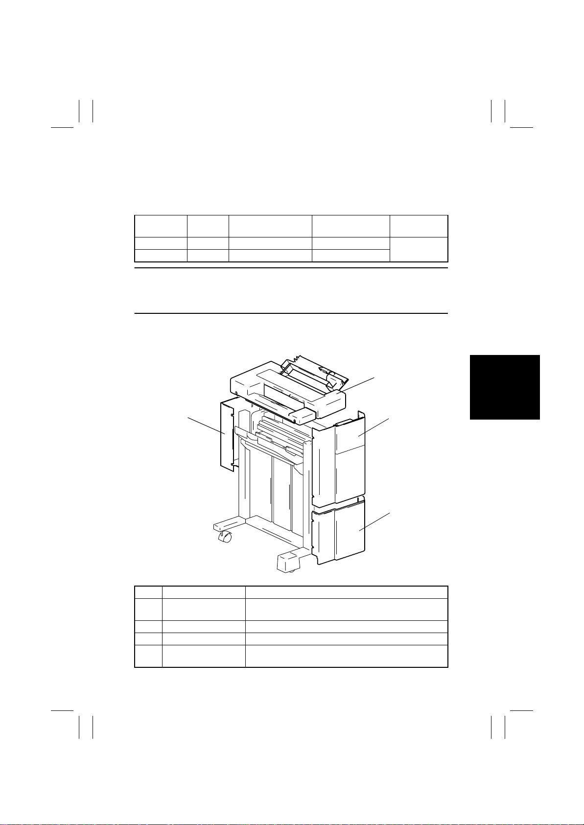
1-2. Removal of the Exterior Parts
1
4
2
3
4643D001AA
No. Part Name Removal Procedure
1 Upper Cover Open the Misfeed Clearing Cover and remo v e one scre w;
2 Upper Front Cover Loosen four screws and take off the cover.
3 Lower Front Cover Loosen two screws and take off the cover.
4 Rear Cover Remove one screw, loosen three screws, and take off the
then loosen three screws and take off the cover.
cover.
D-1
Page 24
FrameMaker Ver.5.5(PC) FS-135 OPTION FOR 8020/8031
02.08.23
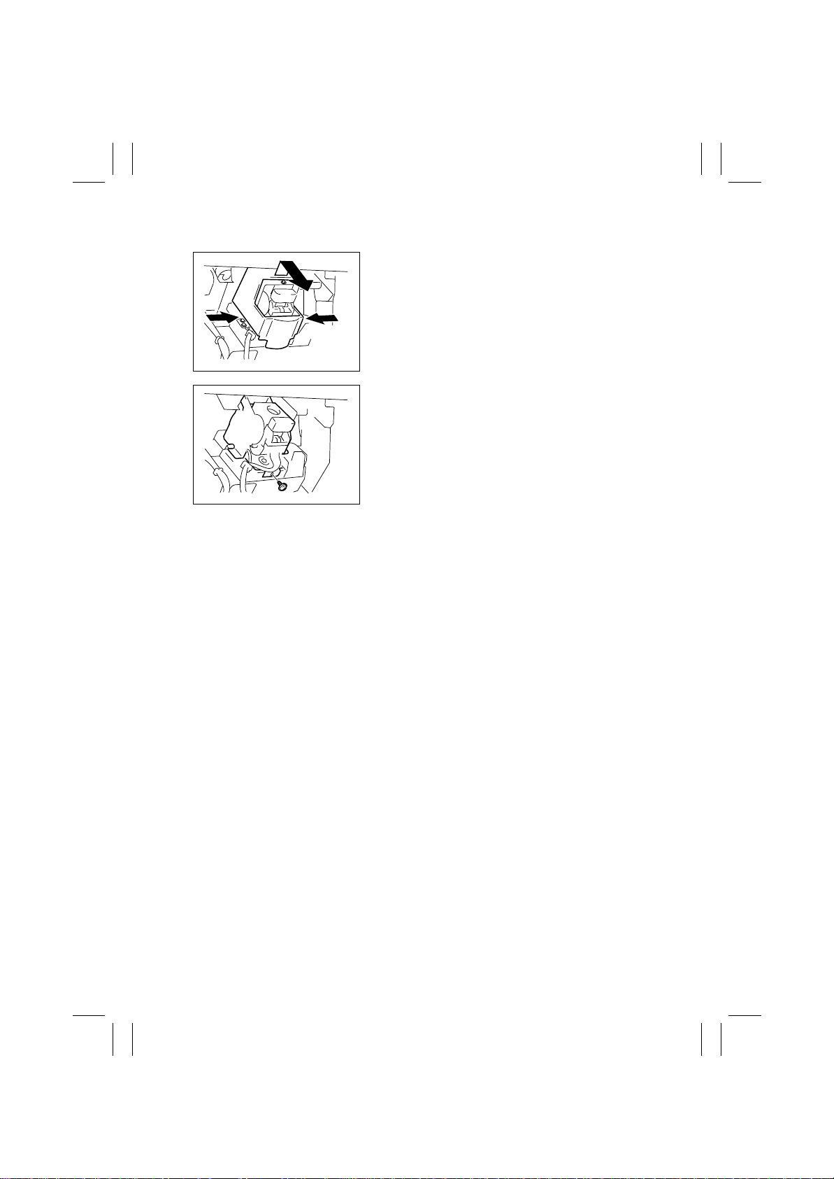
1-3. Removal of the Stapling Unit
1. Holding both sides of the cover, lift the cover up
and take it off.
4643D004AC
2. Remove one screw and remove the Stapling Unit
from the moving cradle.
3. Remove the screw, unplug the connector, and
remove the Stapling Unit.
4643D005AG
D-2
Page 25
FrameMaker Ver.5.5(PC) FS-135 OPTION FOR 8020/8031
02.08.23
2. ADJUSTMENTS
2-1. Adjustment of the Solenoids
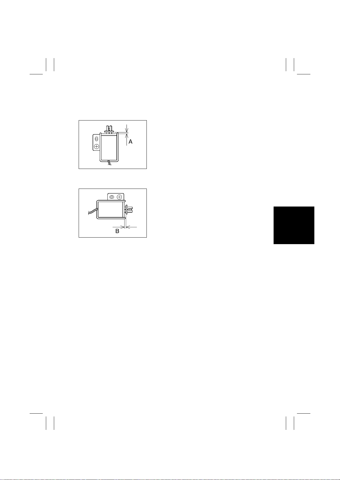
(1) Adjustment of the Upper/Lower Entrance Switching Solenoid (SL1)
1. Loosen one screw that secures the solenoid in
position.
2. Move the solenoid up or down and, when dimension A measures 4.4 mm, tighten the screw.
4643D010AA
(2) Adjustment of the 1
4643D011AA
st
Tray Entrance Selecting Solenoid (SL2)
1. Loosen one screw that secures the solenoid in
position.
2. Move the solenoid to the right or left and, when
dimension B measures 3.6 mm, tighten the screw .
D-3
Page 26

FrameMaker Ver.5.5(PC) FS-135 OPTION FOR 8020/8031
02.08.23
2-2. Timing Belt Tension Adjustment
(1) Adjustment of the Upper Entrance Motor (M4) Timing Belt
1. Loosen two screws.
2. Move the mounting bracket and, when the belt
deflects 4 mm at C, tighten the two screws.
4643D012AB
(2) Adjustment of the Lower Entrance Motor (M2) Timing Belt
1. Loosen two screws.
2. Move the mounting bracket and, when the belt
deflects 2 mm at D, tighten the two screws.
4643D013AB
(3) Adjustment of the Exit Motor (M3) Timing Belt
1. Loosen three screws.
2. Move the mounting bracket and, when the belt
deflects 3 mm at E, tighten the three screws.
4643D014AB
D-4
Page 27
FrameMaker Ver.5.5(PC) FS-135 OPTION FOR 8020/8031
02.08.23
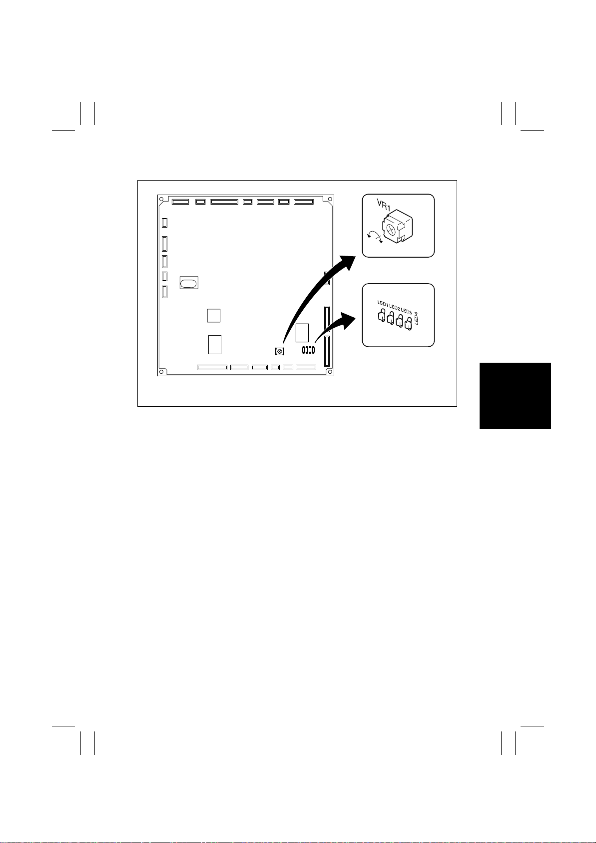
2-3. Adjustment of the Elevator Tray Upper Limit Sensor
4643D015AB
1. Set up the sensor test mode.
2. Turn VR1 on PWB-A fully counterclockwise.
3. Using a sheet of paper, block the Elevator Tray Upper Limit Sensor LED (PWB-C).
4. Check that LED4 on PWB-A turns OFF. If it stays ON, slowly turn VR1 clockwise and
stop turning it as soon as the LED turns OFF.
D-5
Page 28

FrameMaker Ver.5.5(PC) FS-135 OPTION FOR 8020/8031
02.08.23
Blank page
D-6
Page 29

FrameMaker Ver.5.5(PC) FS-135 OPTION FOR 8020/8031
02.08.23
TROUBLESHOOTING
Page 30

FrameMaker Ver.5.5(PC) FS-135 OPTION FOR 8020/8031
02.08.23
Blank page
Page 31
FrameMaker Ver.5.5(PC) FS-135 OPTION FOR 8020/8031
02.08.23
1. SENSOR CHECK
• To permit easy and safe checks of sensors, the sensor input data are checked when the
copier and the Finisher are in the standby state (including a misfeed, malfunction, and
closure failure condition), thereby determining if correct signals are properly input to the
sensors.
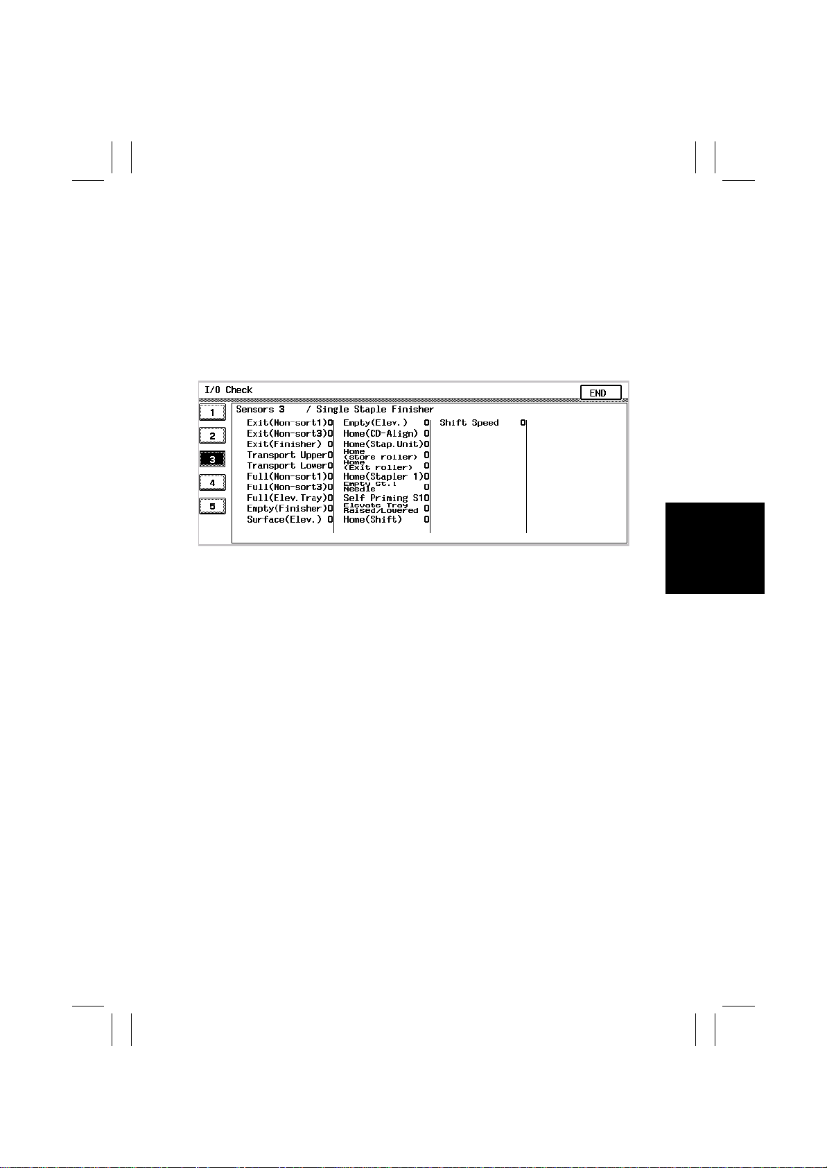
1-1. Sensor Check Screen
• From the “Tech. Rep. Mode” menu, select “State Confirm” and then “I/O Check.”
• The following screens are only typical and port data may look differently on actual copi-
ers.
4684T101
T-1
Page 32
FrameMaker Ver.5.5(PC) FS-135 OPTION FOR 8020/8031
02.08.23
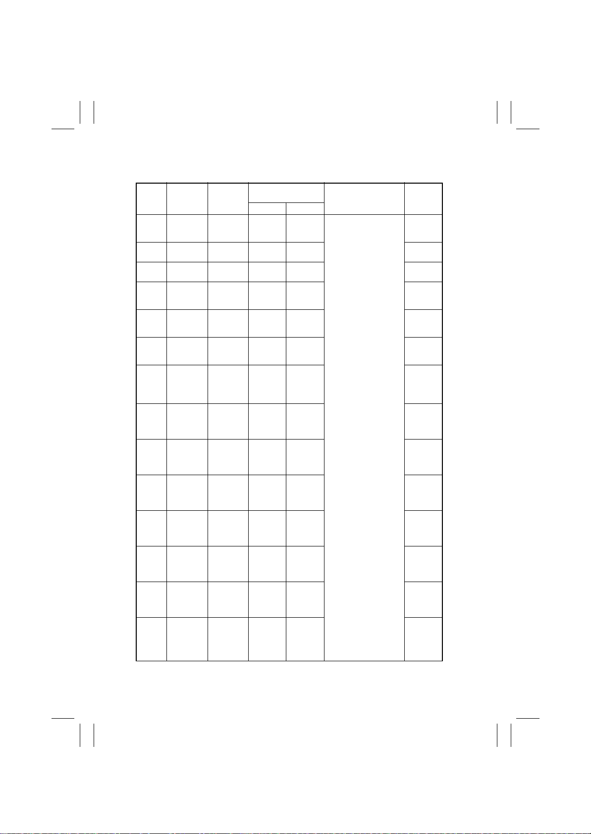
1-2. Sensor Check List
<Sensors 4>
Operation Characteris-
tics/Panel Display
10
Paper
present
Paper
present
Paper
present
Paper
present
Paper
present
Blocked Unblocked PJ19A-3
Paper
present
Blocked Unblocked PJ19A-12
Paper
present
Paper
present
Blocked Unblocked PJ25A-9
Blocked Unblocked PJ25A-6
Blocked Unblocked PJ22A-3
Blocked Unblocked PJ20A-6
Paper not
present
Paper not
present
Paper not
present
Paper not
present
Paper not
present
Paper not
present
Paper not
present
Paper not
present
Symbol
PC1
PC19
PC3
PC4
PC2
PC6
PC20
PC7
PC5
PWB-D
PC8
PC9
PC14
PC12
Panel
Display
Exit
(Non-sort1)
Exit
(Non-sort3)
Exit
(Finisher)
Transport
Upper
Transport
Lower
Full
(Non-sort1)
Full
(Non-sort3)
Full (Elev.
Tray)
Empty
(Finisher)
Surface
(Elev .)
Empty
(Elev .)
Home
(CD-Align)
Home
(Stap. Unit)
Home
(store
roller)
Signal
Name
1st Tray
Exit
Sensor
3rd Tray
Exit Sensor
Storage
Sensor
Upper
Entrance
Sensor
Lower
Entrance
Sensor
1st T ray Full
Detecting
Sensor
3rd Tray
Full
Detecting
Sensor
Elevator
Tray Full
Detecting
Sensor
Finisher
Tray Paper
Detecting
Sensor
Elevator
Tray Up pe r
Limit Sensor PQ
Elevator
Tray Paper
Detecting
Sensor
CD Aligning Home
Position
Sensor
Staple
Home
Position
Sensor
Storage
Roller
Home Position
Sensor
Input Board CN/PJ No.
PJ19A-6
PJ14A-6
PJ20A-3
PJ20A-9
PJ19A-8
PJ14A-3
Control Board (PWB-A)
PJ25A-2
PJ21A-2
T-2
Page 33
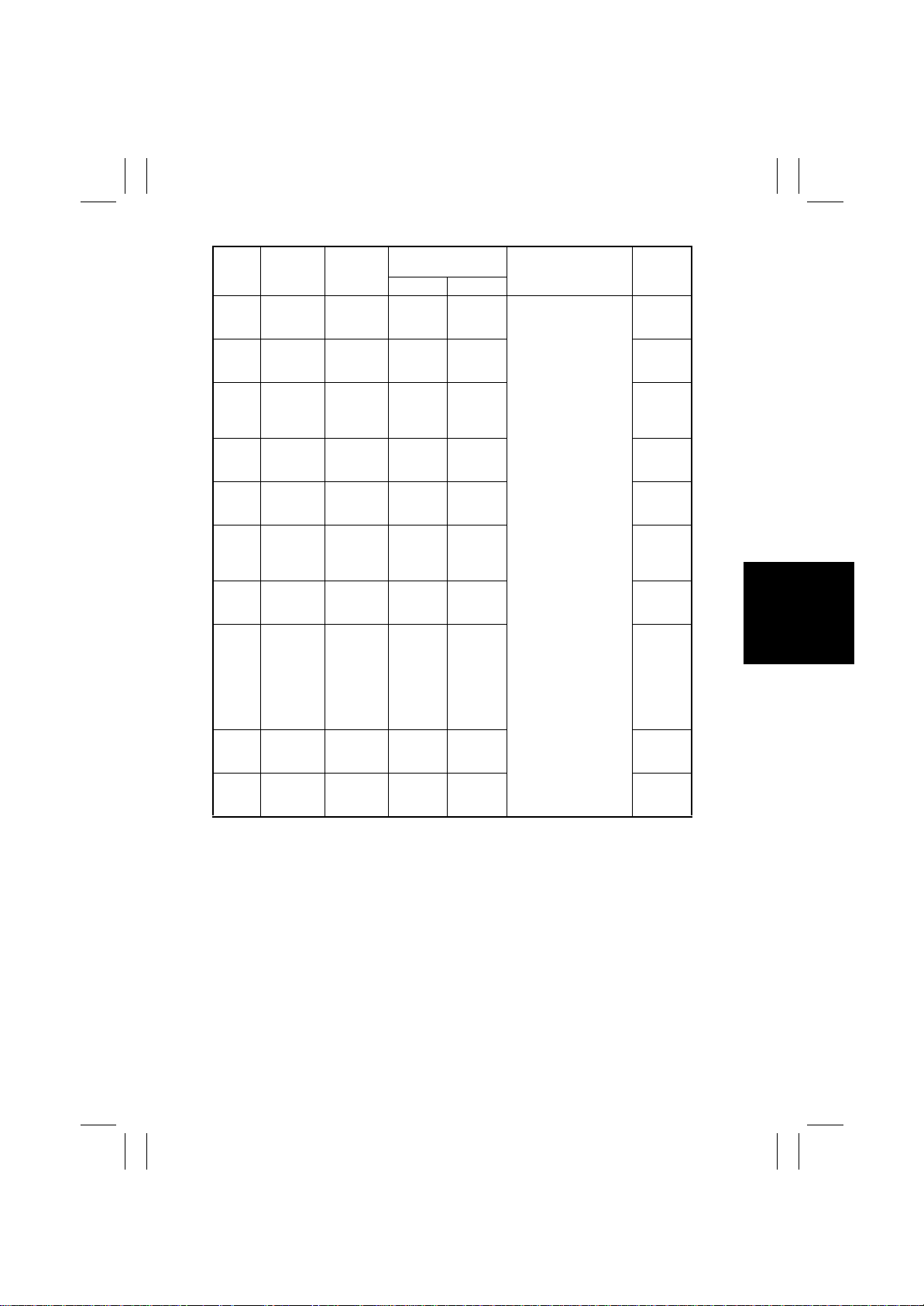
FrameMaker Ver.5.5(PC) FS-135 OPTION FOR 8020/8031
02.08.23
–
–
–
–
–
–
Panel
Display
Home
(Exit roller)
Home
(Stapler 1)
Empty St. 1
Needle
Self
Priming S1
Home
✽
(Stapler 2)
Empty St.
✽
2 Needle
Self
✽
Priming S2
Elevate
Tray
Raised/
Lowered
Home
(Shift)
Symbol
PC13
S2
S3
PC10
PC11 Shift Speed
Signal
Name
Exit Rolls
Home Position Sensor
Stapler
Home
Sensor 1
Staple
Empty
Detecting
Sensor 1
Self-Priming
Sensor 1
Stapler
Home
Sensor 2
Staple
Empty
Detecting
Sensor 2
Self-Priming
Sensor 2
Elevator
Tray Up pe r
Limit Sensor,
Elevator
Tray L ower
Limit Sensor
Shift Home
Position
Sensor
Shift Motor
Pulse Sensor
Operation Characteris-
tics/Panel Display
10
Blocked Unblocked
Unblocked Blocked PJ23A-2
Unblocked Blocked PJ23A-4
Unblocked Blocked PJ23A-3
Unblocked Blocked PJ24A-2
Unblocked Blocked PJ24A-4
Unblocked Blocked PJ24A-3
ON OFF PJ4A-4
Blocked Unblocked PJ25A-12
Unblocked Blocked PJ25A-14
Input Board CN/PJ No.
PJ19A-15
Control Board (PWB-A)
T-3
Page 34

FrameMaker Ver.5.5(PC) FS-135 OPTION FOR 8020/8031
02.08.23
1-3. Sensor Check Procedure
1. When a misfeed or malfunction occurs, select “T ech. Rep. Mode” → “State Confirm” →
“I/O Check” → “Sensors 4.”
2. Check the input of the sensor that is probably faulty.
st
[Example] The 1
<Procedure>
1. Clear the misfeed and reset the misfeed condition.
2. Select “Tech. Rep. Mode” → “State Confirm” → “I/O Check” → “Sensors 4.”
3. Check that the data for “Exit (Non-sort1)” on the screen is “0.”
4. Check that the data changes from “0” to “1” when the 1
blocked.
Tray Exit Sensor is probably responsible for a paper transport misfeed:
st
Tray Exit Sensor (PC1) is
1: PC1 is operational; 0: PC1 is faulty
T-4
Page 35
FrameMaker Ver.5.5(PC) FS-135 OPTION FOR 8020/8031
02.08.23
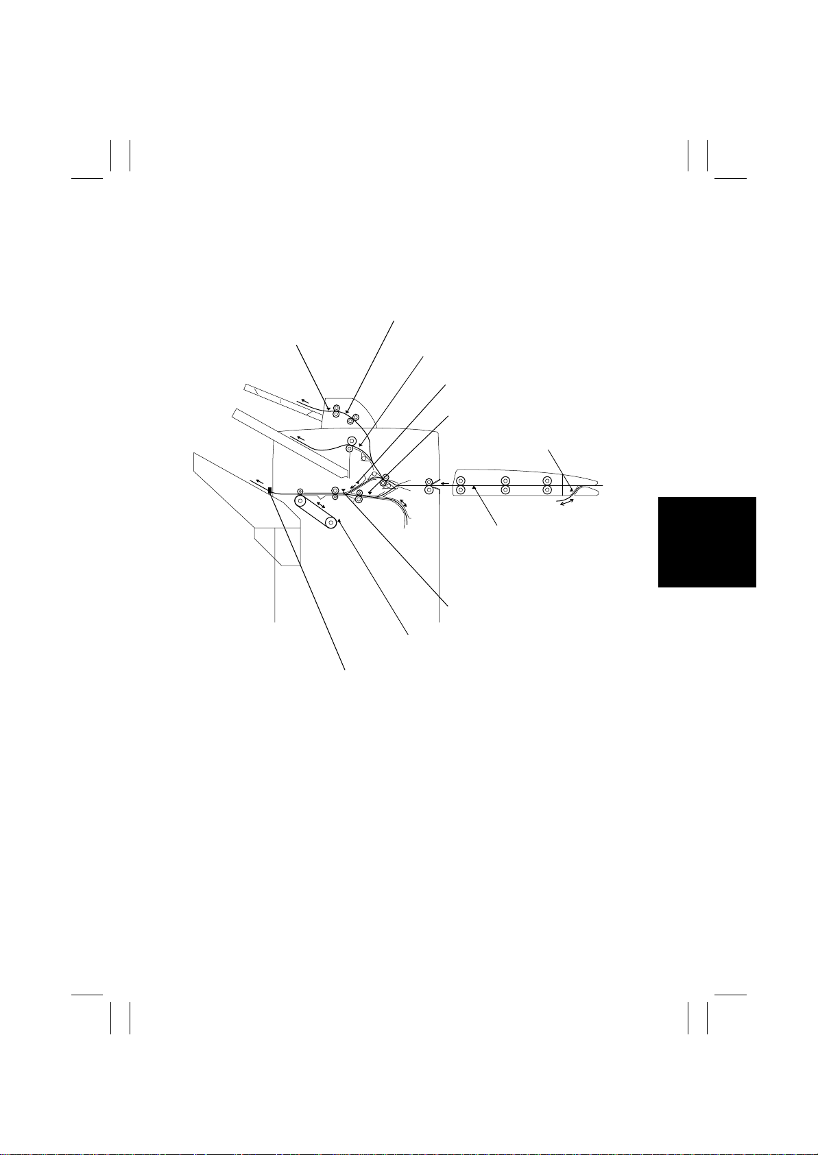
2. MISFEED DETECTION AND TROUBLESHOOTING PROCEDURES
2-1. Misfeed Detecting Sensor Layout
rd
Tray Exit Sensor (PC19)
3
3rd Tray Full Detecting Sensor (PC20)
st
Tray Exit Sensor (PC1)
1
Upper Entrance Sensor (PC4)
Lower Entrance Sensor (PC2)
Turnover Empty Detecting Sensor
(PC6)
Paper Sensor (PC1)
Storage Sensor (PC3)
Finisher Tray Paper Detecting Sensor (PC5)
Elevator Tray Upper Limit Sensor LED/PQ (PWB-C/D)
4653T001AB
T-5
Page 36
FrameMaker Ver.5.5(PC) FS-135 OPTION FOR 8020/8031
02.08.23
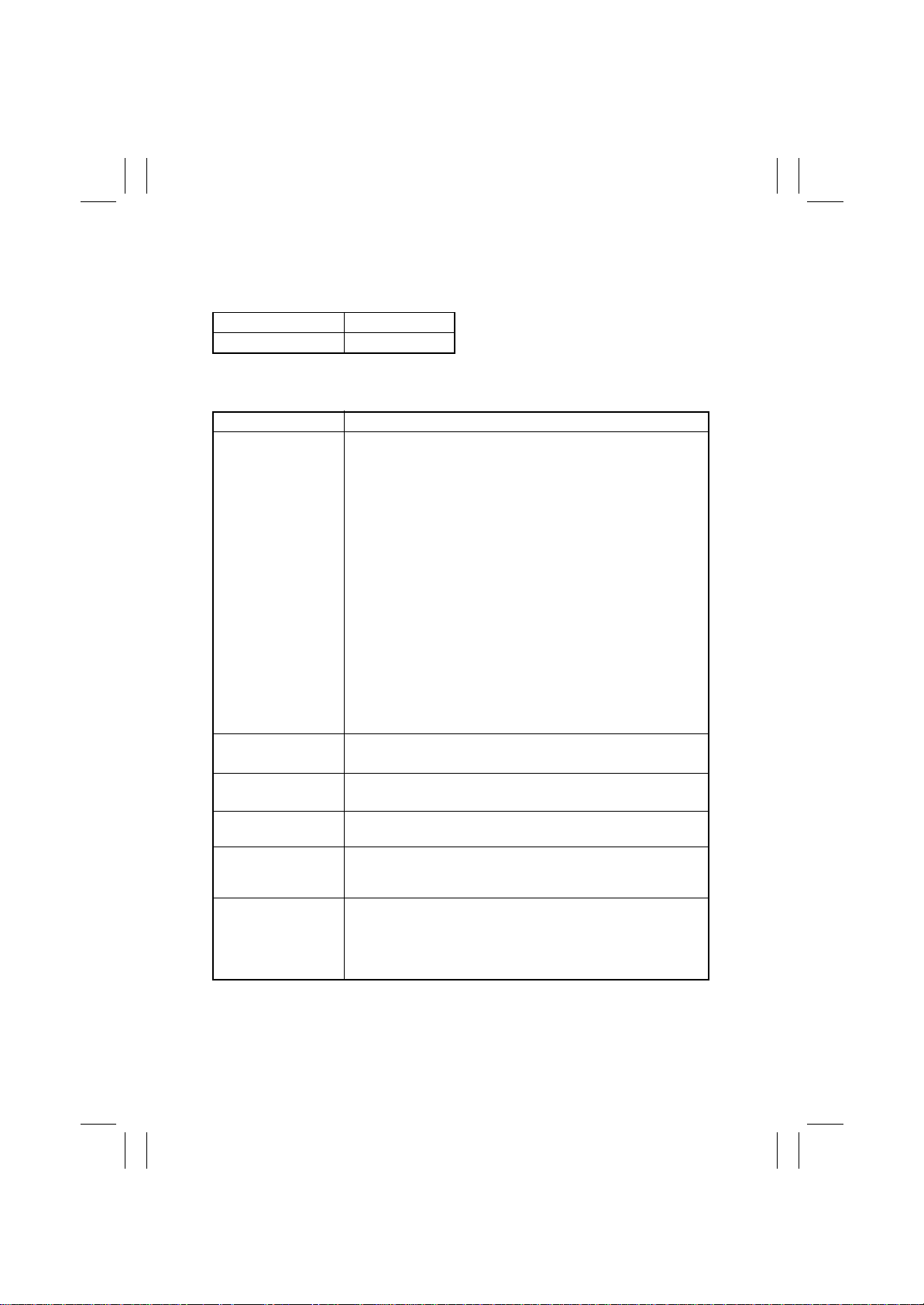
2-2. Misfeed Detection
• When a misfeed occurs, the Touch Panel of the copier gives a message and shows the
locations where the misfeed has occurred and paper is located.
Misfeed location Blinking
Paper location ON
• The misfeed display can be reset by unlocking and sliding the Finisher away from the
copier, and the sliding the Finisher back against the copier.
Type Detection Timing
• The Paper Sensor (PC1) of the Horizontal Transport Unit is not
blocked even after the lapse of a given period of time after the
leading edge of the paper has unblock ed the P aper Exit Sensor
of the copier.
• The Paper Sensor (PC1) of the Horizontal Transport Unit is not
unblocked even after the lapse of a given period of time after
the leading edge of the paper has blocked the sensor.
st
Tray Exit Sensor (PC1) is not blocked even after the
lapse of a given period of time after the leading edge of the
paper has blocked the Paper Sensor (PC1) of the Horizontal
Transport Unit.
lapse of a given period of time after the leading edge of the
paper has blocked the Paper Sensor (PC1) of the Horizontal
Transport Unit.
lapse of a given period of time after the leading edge of the
paper has blocked the Paper Sensor (PC1) of the Horizontal
Transport Unit.
lapse of a given period of time after it has been blocked.
lapse of a given period of time after it has been blocked.
lapse of a given period of time after it has been blocked.
Transport misfeed
st
Misfeed at the 1
exit
Misfeed at the 3
exit (FT-331)
Misfeed at the Elev ator
Tray exit
Paper stack exit
misfeed
Staple misfeed
Tray
rd
Tray
• The 1
• The Upper Entrance Sensor (PC4) is not block ed even after the
• The Lower Entrance Sensor (PC2) is not block ed e ven after the
• The 1st Tray Exit Sensor (PC1) is not unblocked even after the
• The 3rd Tray Exit Sensor (PC19) is not unbloc k ed even after the
• The Storage Sensor (PC3) is not unblocked even after the
The Finisher Tray Paper Detecting Sensor (PC5) remains activated when a copy stack, which has been stapled together, is fed
out.
The Staple Home Position Sensor (PC14) is not blocked ev en
after the lapse of a given period of time after the Stapling Motor
has started turning forward, and the sensor is blocked within a
given period of time after the Stapling Motor has thereafter
started turning backward.
T-6
Page 37
FrameMaker Ver.5.5(PC) FS-135 OPTION FOR 8020/8031
02.08.23
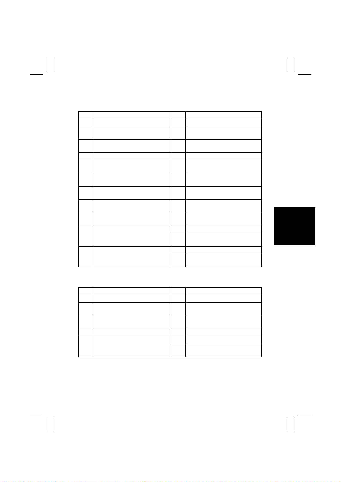
2-3. Misfeed Troubleshooting Procedures
(1) Transport misfeed
Step Check Result Action
1 Paper meets specifications. NO Change paper.
2 Paper is curled, wavy, or damp. YES Change paper.
3 Foreign object on paper path, or dirty
or deformed paper path.
4 Dirty, deformed, or worn roller or roll. YES Clean or change.
5 Entrance Motor (M1) turns after Start
key has been pressed.
6 Upper Entrance Motor (M4) turns
after Start key has been pressed.
7 Lower Entrance Motor (M2) turns
after Start key has been pressed.
8 Paper Sensor (PC1) I/O Check:
Horiz. Transport of Sensors
9 Upper Entrance Sensor (P C4) I/O
Check: Transport Upper of Sensors
10 Lower Entrance Sensor (PC2) I/O
Check: Transport Lower of Sensors
11 Storage Sensor (PC3) I/O Check:
Exit (Finisher) of Sensors
Instruct user in how to store paper.
YES Clean or change.
NO Change M1 or PWB-A.
NO Change M4 or PWB-A.
NO Change M2 or PWB-A.
NO Correct actuator.
Change PC1.
NO Correct actuator.
Change PC4.
YES Change PWB-A.
NO Correct actuator.
Change PC2.
YES Change PWB-A.
NO Correct actuator.
Change PC3.
st
(2) Misfeed at the 1
Step Check Result Action
1 Paper meets specifications. NO Change paper.
2 Paper is curled, wavy, or damp. YES Change paper.
3 Foreign object on paper path, or dirty
or deformed paper path.
4 Dirty, deformed, or worn roller or roll. YES Clean or change.
st
5
Tray Exit Sensor (PC1) I/O Check:
1
Exit (Non-sort) of Sensors
Tra y exit
Instruct user in how to store paper.
YES Clean or change.
YES Change PWB-A.
NO Correct actuator.
Change PC1.
T-7
Page 38
FrameMaker Ver.5.5(PC) FS-135 OPTION FOR 8020/8031
02.08.23
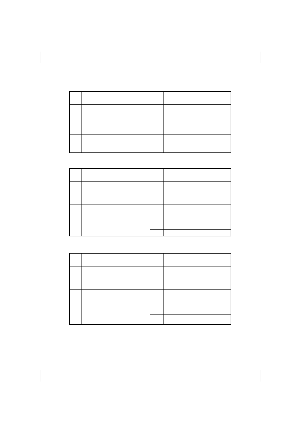
(3) Misfeed at the 3rd Tray exit (FT-331)
Step Check Result Action
1 Paper meets specifications. NO Change paper.
2 Paper is curled, wavy, or damp. YES Change paper.
Instruct user in how to store paper.
3 Foreign object on paper path, or dirty
or deformed paper path.
4 Dirty, deformed, or won roller or roll. YES Clean or change.
rd
5
Tray Exit Sensor (PC19) I/O
3
Check: The 3
(4) Misfeed at the Elevator Tray exit
Step Check Result Action
1 Paper meets specifications. NO Change paper.
2 Paper is curled, wavy, or damp. YES Change paper.
3 Foreign object on paper path, or dirty
or deformed paper path.
4 Dirty, deformed, or worn roller or roll. YES Clean or change.
5 Exit Motor (M3) turns after Start key
has been pressed.
6 Storage Sensor (PC3) I/O Check:
Exit (Finisher) of Sensors
rd
Tray: Exit
YES Clean or change.
YES Change PWB-A.
NO Correct actuator.
Change PC19.
Instruct user in how to store paper.
YES Clean or change.
NO Change M3 or PWB-A.
YES Change PWB-A.
NO Change PC3.
(5) Paper stack exit misfeed
Step Check Result Action
1 Paper meets specifications. NO Change paper.
2 Paper is curled, wavy, or damp. YES Change paper.
Instruct user in how to store paper.
3 Foreign object on paper path, or dirty
or deformed paper path.
4 Dirty, deformed, or worn roller or roll. YES Clean or change.
5 Exit Motor (M3) turns after Start key
has been pressed.
6 Finisher Tra y P aper Detecting Sensor
(PC5) I/O Check: Empty (Finisher) of
Sensors
YES Clean or change.
NO Change M3 or PWB-A.
YES Change PWB-A.
NO Change PC5.
T-8
Page 39

FrameMaker Ver.5.5(PC) FS-135 OPTION FOR 8020/8031
02.08.23
(6) Staple misfeed
Step Check Result Action
1 Stapling Motor is overloaded. YES Check drive couplings.
NO Change Stapling Unit or PWB-A.
T-9
Page 40
FrameMaker Ver.5.5(PC) FS-135 OPTION FOR 8020/8031
02.08.23
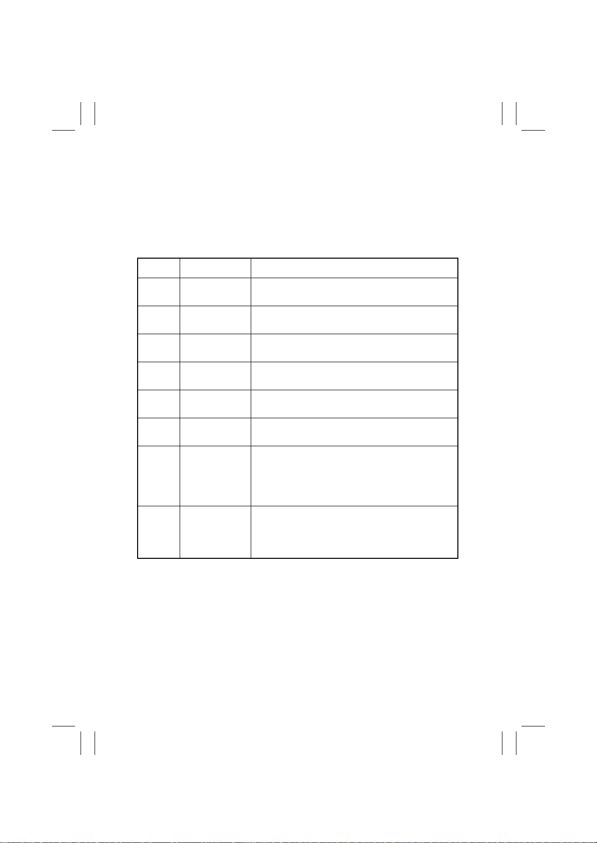
3. MALFUNCTION DETECTION AND TROUBLESHOOTING PROCEDURES
3-1. Malfunction Detection
• Any of the following operation faul ts can be detected and the corresponding malfunction
code is displayed on the copier Touch Panel.
• The malfunction detection can be reset by opening and closing the Front Door of the
copier.
Malfunction
Code
C0B20 Stapling Unit Moving
C0B30 CD Aligning Motor
C0B48 Exit Roller/Rolls
C0B4A Storage Roller/Rolls
C0B50 Stapling Motor 1
C0B54 Stapling Motor 2
C0B80 Shift Motor (M8) drive
C0BA0 Elevator Motor (M7)
Description Detection Timing
Motor (M6) drive malfunction
(M5) drive malfunction
Spacing Motor (M13)
drive malfunction
Spacing Motor (M12)
drive malfunction
drive malfunction
drive malfunction
malfunction
drive malfunction
The Staple Home Position Sensor (PC14) does not go HIGH even
after the lapse of a given period of time after M6 has been energized (to return the Stapling Unit to its home position).
The CD Aligning Home Position Sensor (PC9) does not go LOW
even after the lapse of a given period of time after M5 has been
energized (to return the Aligning Plate to its home position).
The Exit Rolls Home Position Sensor (PC13) does not go HIGH
even after the lapse of a given period of time after M13 has been
energized (to start spacing/pressure sequence).
The Storage Roller Home Position Sensor (PC12) does not go
HIGH even after the lapse of a given period of time after M12 has
been energized (to start spacing/pressure sequence).
Stapling Motor 1 is not deenergized even after the lapse of a given
period of time after it has been energized (to start a stapling
sequence).
Stapling Motor 2 is not deenergized even after the lapse of a given
period of time after it has been energized (to start a stapling
sequence).
• The Shift Home Position Sensor (PC10) does not go HIGH
even after the lapse of a given period of time after M8 has been
energized (to start returning the Elevator Tray to its home position).
• The Shift Home Position Sensor (PC10) does not go LOW even
after the lapse of a given period of time after M8 has been energized (to start moving the Elevator Tray for job offset).
• The Elevator Tray Upper Limit Sensor PQ (PWB-D) is not activated even after the lapse of a given period of time after M7 has
been energized (to start raising the Elevator Tray).
• The Elevator Tray Upper Limit Switch (S2) or Elevator Tray
Lower Limit Switch (S3) is actuated after M7 has been energized.
T-10
Page 41
FrameMaker Ver.5.5(PC) FS-135 OPTION FOR 8020/8031
02.08.23
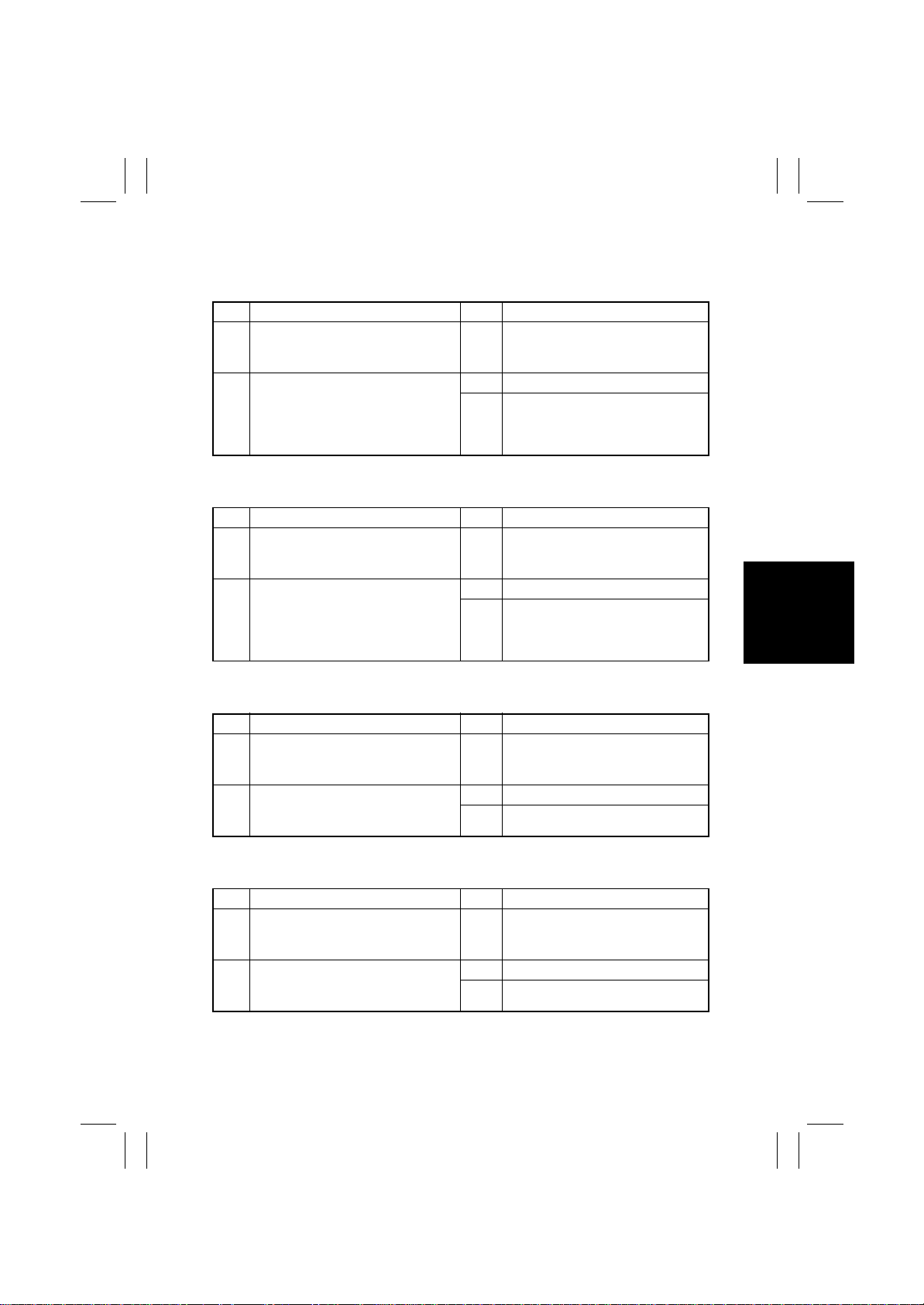
3-2. Malfunction Troubleshooting Procedures
(1) C0B20
Step Check Result Action
1 Staple Home Position Sensor (PC14)
I/O Check: Home (Stap. Unit) of Port
Signals
2 Turn OFF the Power Switch, move
the Stapling Unit out of its home position, and turn ON the Power Switch.
Drive of the Stapling Unit Moving
Motor (M6) at this time
(2) C0B30
Step Check Result Action
1 CD Aligning Home Position Sensor
(PC9) I/O Check: Home (CD Align) of
Port Signals
2 Turn OFF the Power Switch, move
the Aligning Plate out of its home
position, and turn ON the Power
Switch. Drive of the CD aligning
Motor (M6) at this time
NO Change PC14.
YES Change PWB-A.
NO Change M6 or PWB-A.
NO Change PC9.
YES Change PWB-A.
NO Change M5 or PWB-A.
(3) C0B48
Step Check Result Action
1 Exit Rolls Home Position Sensor
(PC13) I/O Check: Home (Exit roller)
of Port Signals
2 Drive of the Exit Roller/Rolls Spacing
Motor (M13) when the Power Switch
is turned OFF and ON
(4) C0B4A
Step Check Result Action
1 Storage Roller Home Position Sensor
(PC12) I/O Check: Home (Store
roller) of Port Signals
2 Drive of the Storage Roller/Rolls
Spacing Motor (M12) when the
Power Switch is turned OFF and ON
NO Change PC13.
YES Change PWB-A.
NO Change M13 or PWB-A.
NO Change PC12.
YES Change PWB-A.
NO Change M12 or PWB-A.
T-11
Page 42
FrameMaker Ver.5.5(PC) FS-135 OPTION FOR 8020/8031
02.08.23
(5) C0B50
Step Check Result Action
1 Stapling Motor 1 is overloaded. YES Check drive coupling.
NO Change Stapling Unit 1 or PWB-A.
(6) C0B80
Step Check Result Action
1 Shift Home Position Sensor (PC10) I/
O Check: Home (Shift) of Port Signals
2 Shift Motor Pulse Sens or (PC11) I/O
Check: Shift Speed of Port Signals
3 Shift Motor (M8) operation:
The voltage across PJ5A-4 on PWBA and GND change from LOW to
HIGH after the Start key has been
pressed in the Sort mode.
NO Change PC10.
NO Change PC11.
YES Change M8.
NO Change PWB-A.
(7) C0BA0
Step Check Result Action
1 Elevator Tray Upper Limit Sensor PQ
(PWB-D) I/O Check: Surface (Elev.)
of Sensors
2 Elevator Tray Upper Limit Switch (S2)
I/O Check: Elevate Tray Raised/Lowered of Port Signals
3 Elevator T r ay Lower Limit Switch (S3)
I/O Check: Elevate Tray Raised/Lowered of Port Signals
4 Elevator Motor (M7) operation:
The voltage across PJ5A-1 on PWBA and GND (when the Elevator Tray
goes down) and that across PJ5A-2
on PWB-A and GND (when the Elevator Tray goes up) goes from LOW
to HIGH after the Start key has been
pressed in the Sort mode.
NO Change PWB-C or PWB-D.
NO Change S2.
NO Change S3.
YES Change M7.
NO Change PWB-A.
T-12
 Loading...