

Page 1
FrameMaker Ver.5.5E(PC) Di350 DIS/REASSEMBLY, ADJUSTMENT
98.12.09
Di350
DIS/REASSEMBLY,
ADJUSTMENT
18605
Page 2

FrameMaker Ver.5.5E(PC) Di350 DIS/REASSEMBLY, ADJUSTMENT
98.12.09
CONTENTS
1. SERVICE INSTRUCTIONS .............................................................................D-1
1-1. IDENTIFICATION OF FUSES AND CIRCUIT BREAKER S ....................D-1
1-2. PRECAUTIONS FOR HANDLING THE LASER EQUIPMENT ...............D-1
1-3. INSTRUCTIONS FOR HANDLING THE PWBs WITH MOS ICs .............D-2
1-4. HANDLING OF THE IMAGING CARTRIDGE ............. ............... .............D-2
1-5. PARTS WHICH MUST NOT BE TOUCHED ...........................................D-3
(1) Red painted Screws ........................................ ........................... .....D-3
(2) Variable Resistors on Board ..................... .......................................D-3
(3) Other Screws ...................................................................................D-3
2. DISASSEMBLY/REASSEMBLY ......................................................................D-4
2-1. DOORS, COVERS, AND EXTERIOR PARTS: IDENTIFICATION AND
REMOVAL PROCEDURES .....................................................................D-4
2-2. REMOVAL OF CIRCUIT BOARDS AND OTHER ELECTRICAL
COMPOMENTS ....................................................................................... D-7
2-3. PAPER TAKE-UP/TRANSPORT SECTION ............................................D-10
(1) Replacement of the Paper Take-Up Roll .........................................D-10
(2) Replacement of the Paper Dust Remover .......................................D-10
(3) Cleaning of the Paper Dust Remover ...................... ........................D-11
(4) Cleaning of the Side Cover ..............................................................D-11
(5) Cleaning of the Duplex Unit Cover ..................................................D-11
2-4. OPTICAL SECTION ............................................................................. ...D-12
(1) Removal of the IR Unit ....................................................................D-12
(2) Removal of the PH Unit ...................................................................D-13
(3) Removal of the CCD Unit ................................................................D-15
(4) Cleaning of the Scanner Rails/Bushings .........................................D-15
(5) Cleaning of the Mirrors .................................................................... D-16
(6) Cleaning of the Lens ................................. ............... ........................D-16
(7) Cleaning of the Original Glass ................ .............................. ...........D-16
(8) Removal of the Scanner ..................................................................D-16
(9) Removal of the Scanner Drive Cables ............................................ D-18
(10) Winding of the Scanner Drive Cables ..............................................D-19
2-5. IMAGE TRANSFER SECTION ................................................................ D-23
(1) Removal of the Image Transfer Roller .............................................D-23
(2) Cleaning of the Comb Electrode ......................................................D-23
(3) Cleaning of the Pre-Image Transfer Guide Plate ................... .........D-24
(4) Replacement of the Ozone Filter .....................................................D-24
2-6. DEVELOPING SECTION ........................................................................D-25
(1) Removal of the Imaging Cartridge ...................................................D-25
2-7. FUSING SECTION ..................................................................................D-26
(1) Removal of the Fusing Unit .............................................................D-26
(2) Removal of the Fusing Roller Heater Lamp, Fusing Right Roller,
Fusing Left Roller, Fusing Roller Thermistor, Fusing Roller
Thermostat, and Fusing Roller Heater Lamp Fuse .........................D-26
3. ADJUSTMENT ................................................................................................. D-29
3-1. ADJUSTMENT JIGS AND TOOLS USED ...............................................D-29
3-2. ADJUSTMENT REQUIREMENT LIST ....................................................D-29
i
Page 3

FrameMaker Ver.5.5E(PC) Di350 DIS/REASSEMBLY, ADJUSTMENT
98.12.09
3-3. ADJUSTMENT OF BELT TENSION ........................................................D-30
3-4. TEST PRINT .................... ............ ............................................................D-31
3-5. ELECTRICAL/IMAGE ADJUST MENT .......... ...................................... .....D-32
(1) Touch Panel Adj. ............... ............................ ........................... .......D-32
(2) Original Size Detecting Sensor Adjustment (F7-1) ..........................D-33
(3) Loop Adjustment .............................................. ........................... .....D-34
(4) Edge Erase ......................................................................................D-35
(5) Registration (CD) (Printer) ...............................................................D-38
(6) Registration (FD) (Printer) ................ ............................. ..................D-40
(7) Registration (IR) ................................. ............... ........................... ...D-42
(8) Zoom Adjust (IR) ........... ............... ........................... ........................D-46
(9) IR-Erasure Width ........................................... ........................... .......D-50
3-6. OTHER ADJUSTMENTS ......................................................................... D-51
4. MISCELLANEOUS ..........................................................................................D-53
4-1. INSTALLATION OF THE KEY COUNTER SOCKET (OPTION) .............D-53
4-2. REMOUNTING THE EEPROM (IC3A) ....................................................D-54
ii
Page 4
FrameMaker Ver.5.5E(PC) Di350 DIS/REASSEMBLY, ADJUSTMENT
98.12.09
1 SERVICE INSTRUCTIONS
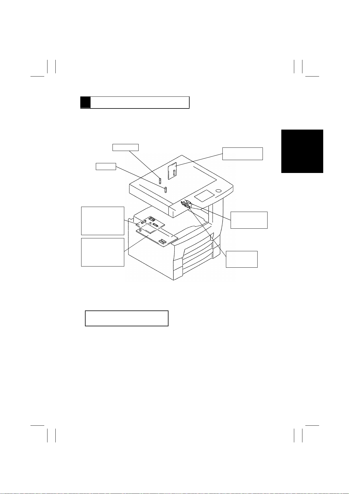
1-1. IDENTIFICATION OF FUSES AND CIRCUIT BREAKERS
125V 3.15A
125V 5A
Master Board
PWB-A125V 3A (F1)
125V 3A (F2)
250V 1A (F3)
250V 1A (F4)
Power Supply Unit 1
PU1 125V 10A (F1)
125V 15A (F2)
250V 3.15A (F3)
250V 3.15A (F4)
Power Supply Unit 2
PU2 125V 5A
Fusing Roller
Heater Lamp Fuse
TF1 125V 15A
Fusing Roller
Thermostat
TS1 250V 10A
1171D016AC
1-2. PRECAUTIONS FOR HANDLING THE LASER EQUIPMENT
•
The laser used in this copier is a semiconductor laser having the following specifications.
Max. power: 5mW
Output wavelength: 770~80nm
•
When laser protective goggles are to be used, select ones with a lens conforming to the
above specifications.
•
When a disassembly job needs to be performed in the laser beam path, such as when
working around the printerhead and PC Drum, be sure first to turn the copier OFF.
•
If the job requires that the copier be left ON, take off your watch and ring and wear laser
protective goggles.
•
A highly reflective tool can be dangerous if it is brought into the laser beam path. Use
utmost care when handling tools on the user’s premises.
•
The printerhead is not maintainable in the field. It is to be replaced as an assembly
including the control board. Never, therefore, attempt t o remo ve the laser diode or adjust
trimmers on the control board.
D-1
Page 5

FrameMaker Ver.5.5E(PC) Di350 DIS/REASSEMBLY, ADJUSTMENT
98.12.09
1-3. INSTRUCTIONS FOR HANDLING THE PWBs WITH MOS ICs
The following precautions must be observed when handling P.W. Boards with MOS
(Metal Oxide Semiconductor) ICs.
During Transportation/Storage:
•
During transportation or when in storage, new P.W. Boards must not be indiscriminately
removed from their protective conductive bags.
•
Do not store or place P.W. Boards in a location exposed to direct sunlight.
•
When it becomes absolutely necessary to remove a Board from its conductive bag or
case, always place it on its conductive mat in an area as free as possible from static electricity.
•
Do not touch the pins of the ICs with your bare hands.
During Replacement:
•
Before unplugging connectors from the P.W. Boards, make sure that the power cord has
been unplugged from the outlet.
•
When removing a Board from its conductive bag or conductive case, do not touch the
pins of the ICs or the printed pattern. Place it in position by holding only the edges of the
Board.
•
Before plugging connectors into the Board, make sure that the power cord has been
unplugged from the power outlet.
During Inspection:
•
Avoid checking the IC directly with a multimeter; use connectors on the Board.
•
Never create a closed circuit across IC pins with a metal tool.
•
When it is absolutely necessary to touch the ICs and other electrical components on the
PW Board, be sure to ground your body.
1-4. HANDLING OF THE IMAGING CARTRIDGE
During Transportation/Storage:
•
Use the specified carton whenever moving or storing the Imaging Cartridge.
•
The storage temperature is in the range between –20°C and +40°C.
•
In summer, avoid leaving the Imaging Cartridge in a car for a long time.
Handling:
•
Ensure that the correct Imaging Cartridge is used.
•
Store the Imaging Cartridge in a site that is not exposed to direct sunlight.
Precautionary Information on the PC Drum Inside the Imaging Cartridge:
•
The PC Drum exhibits greatest light fatigue after being exposed to strong light over an
extended period of time. Never, therefore, expose it to direct sunlight.
•
Use care not to contaminate the surface of the PC Drum with oil-base solvent, fingerprints, and other foreign matter.
•
Do not scratch the surface of the PC Drum.
•
Do not apply chemicals to the surface of the PC Drum.
•
Do not attempt to wipe clean the surface of the PC Drum.
D-2
Page 6
FrameMaker Ver.5.5E(PC) Di350 DIS/REASSEMBLY, ADJUSTMENT
98.12.09
1-5. PARTS WHICH MUST NOT BE TOUCHED
(1) Red painted Screws
Purpose of Application of Red Paint
Red painted screws show that the assembly or unit secured can only be adjusted or set at
the factory and should not be readjusted, set, or removed in the field.
Note that when two or more screws are used on the part in questions, only one representative screw may be marked with red paint.
(2) Variab le Resistors on Board
Do not turn the variable resistors on boards for which no adjusting instructions are given in
“ADJUSTMENT.”
(3) Other Screws
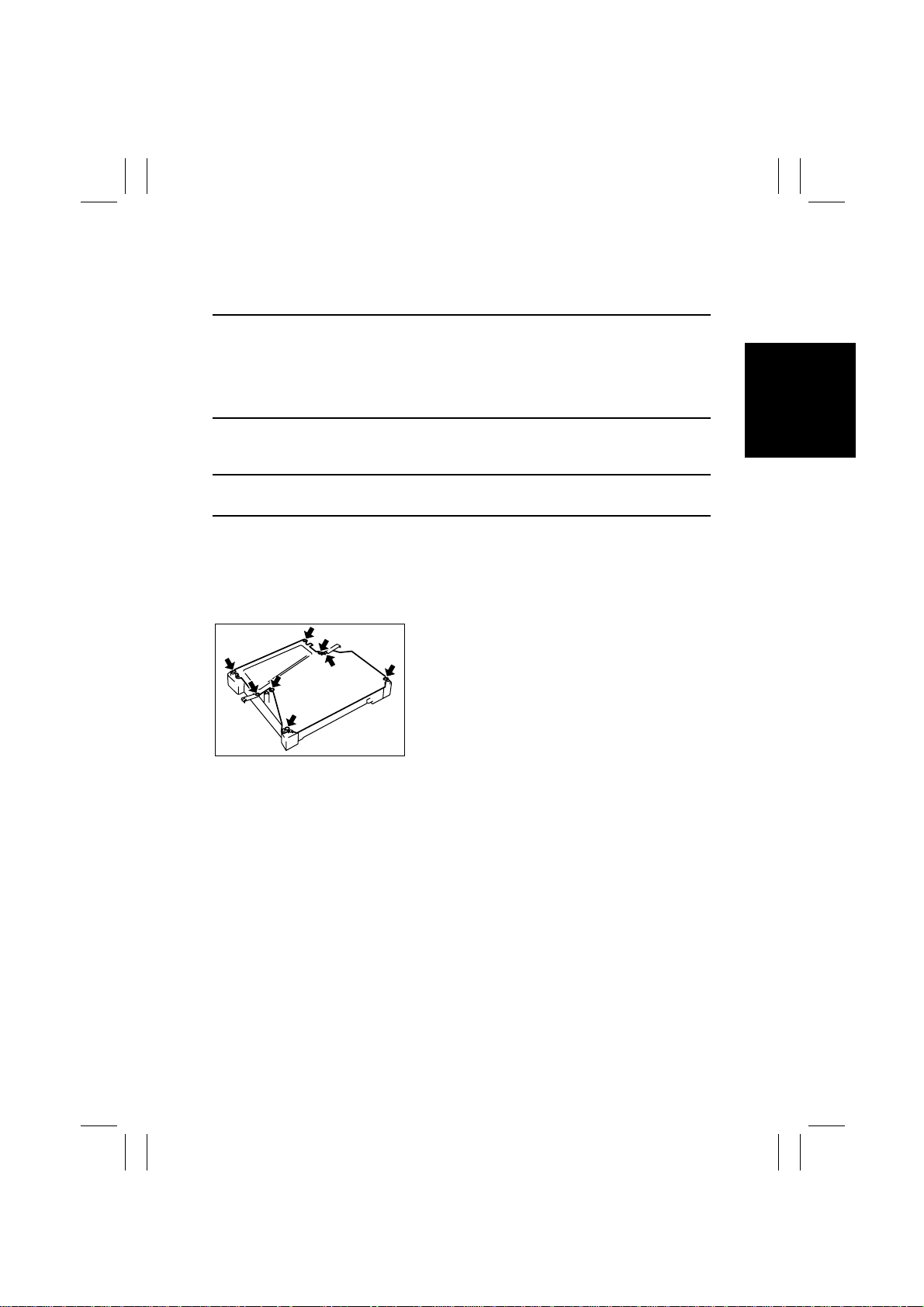
Although not marked with red paint, the following screws must not be loosened or readjusted.
8 screws on the PH Unit Cover
1167D002AB
D-3
Page 7
FrameMaker Ver.5.5E(PC) Di350 DIS/REASSEMBLY, ADJUSTMENT
98.12.09
2 DISASSEMBLY/REASSEMBLY
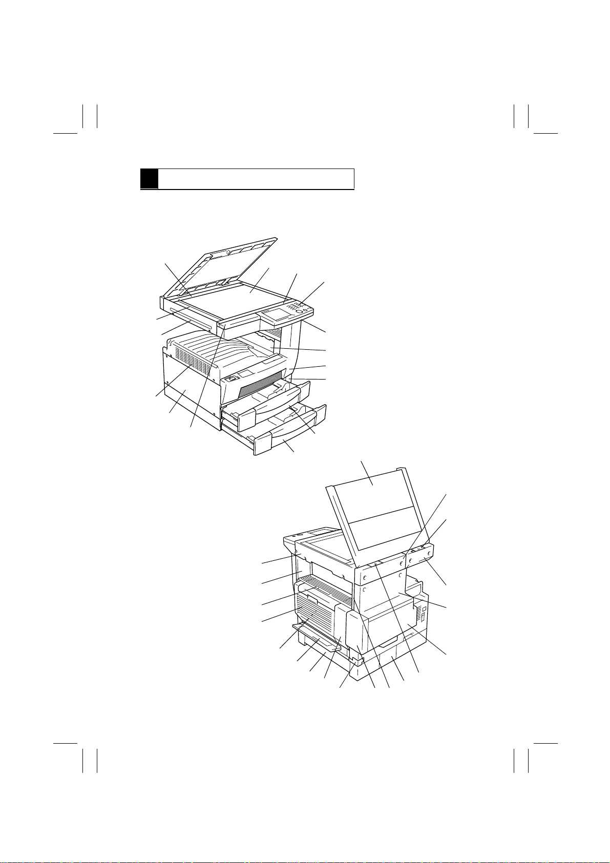
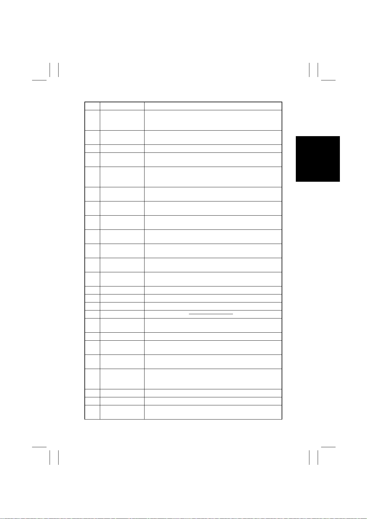
2-1. DOORS, COVERS, AND EXTERIOR PARTS: IDENTIFICA TION
AND REMOVAL PROCEDURES
14
1
15
2
13
12
3
4
5
6
7
8
9
1171D017AA
10
11
16
17
18
34
33
32
31
30
29
D-4
28
27
26
19
20
21
22
23
2425
1171D018AB
Page 8
FrameMaker Ver.5.5E(PC) Di350 DIS/REASSEMBLY, ADJUSTMENT
98.12.09
No. Part Name Removal Procedure
1 ADF Glass Assy. Remove No. 2, 4. → Remove two holding brackets. →
2 Rear Holding
Bracket
3 Original Glass Remove No. 4. → Remove two holding brackets.
4 Front Holding
Bracket
5 Control Panel Remove No. 8. → Remove No. 6. → Remove No. 4. →
6 Front Upper Cover Remove No. 8. → Remove No. 12. → Remove six screws that
7 Exit Lower Cover Remove No. 32. → Remove No. 24. → Unhook the two tabs of
8 Front Cover Slide out No. 10. → Open No. 25. → Remove three screws
9 LED Co ver Slide out No. 10. → Remove one screw that secure the LED
10 MP Cassette Slide out the MP Cassette. → Pushing the tab on the right rail,
11 500-Sheet
Cassette
12 Upper Front Left
Cover
13 Left Cover Remove six screws that secure the Left Cover.
14 Upper Cover Remove two screws that secure the Upper Cover.
15 Left IR Cover Remove two screws that secure the Left IR Cover.
16 Original Cover
17 Rear Right IR
Cover
18 Left Hinge Cover Remove one screw that secure the Left Hinge Cover.
19 Rear Left IR Cover Remove No. 17. → Remove two screws that secure the Rear
20 Rear Upper Cover Remove No. 21. → Remove No. 17. → Remove No. 19. →
21 Rear Lower Cover Remove No. 26. → Remove No. 25. → Open No. 30. → Open
22 Right Hinge Cover Remove one screw that secure the Right Hinge Cover.
23 Connector Cover Remove one screw that secure the Connector Cover.
24 Rear Inside Cover Remove No. 22. → Remove three screws that secure the Rear
Remove two screw caps. → Remove two screws that secure
the ADF Glass Assy.
Remove No. 17, 18. → Remove two screw caps. → Remove
two screws that secure the Rear Holding Bracket.
Remove two screw caps. → Remove two screws that secure
the Front Holding Bracket.
Remove No. 12. → Remove five screws that secure the control
panel and unplug one connector.
secure the Front Upper Cover.
the Exit Lower Cover and remove the Exit Lower Cover.
that secure the Front Cover.
Cover.
pull out the cassette.
Slide out the 500-Sheet Cassette. → Pushing the tabs on both
the right and left rails, pull out the cassette.
Remove No . 4. → Remove two screws that secure the Upper
Front Left Cover.
Remove No . 22. → Remove No. 19. → Remove two screws
that secure the Rear Right IR Cover.
Left IR Cover.
Remove four screws that secure Rear Upper Cover.
No. 32. → Remove five screws that secure the Rear Lower
Cover.
Inside Cover.
D-5
Page 9
FrameMaker Ver.5.5E(PC) Di350 DIS/REASSEMBLY, ADJUSTMENT
98.12.09
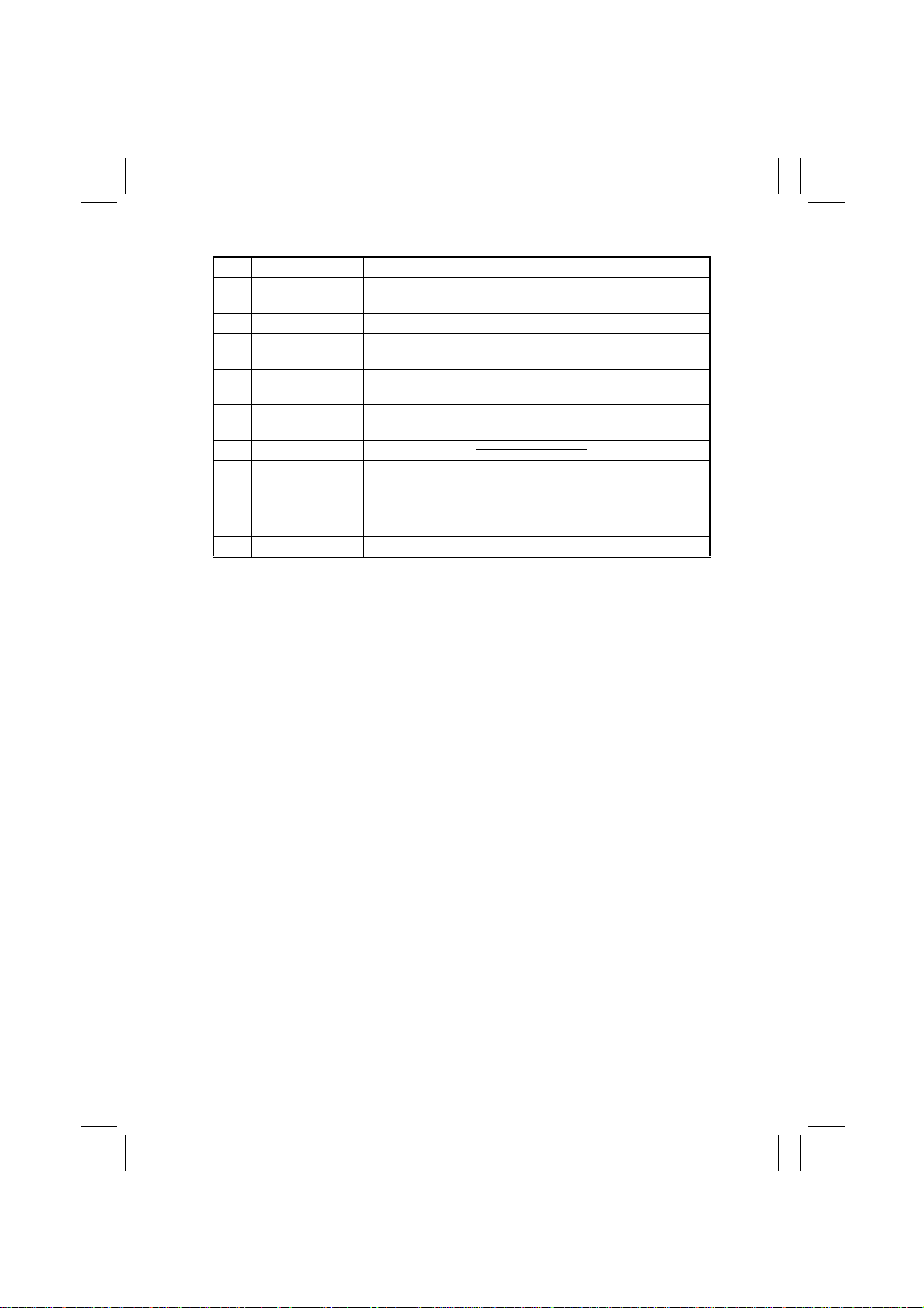
No. Part Name Removal Procedure
25 Toner Bottle Cover Open the Toner Bottle Cover. → Unhook the dowels at four
26 Harness Cover Remove one screw that secure the Harness Cover.
27 Duplex Unit Rear
Cover
28 500-Sheet Cas-
sette Side Cover
29 Manual Bypass
Tray
30 Side Cover
31 Duplex Unit Remove two screws that secure the Duplex Unit.
32 Fusing Unit See D-26.
33 Front Inside Cover Remove No. 8. → Remove No. 32. → Remove two screws that
34 Right IR Cover Remove three screws that secure the Right IR Cover.
places of the Toner Bottle Cover.
Remove No . 31. → Remove two screws that secure the
Duplex Unit Rear Cover.
Open the Side Cover . → Slide the Side Cover to the front and,
at the same time, pull the rear side out of the frame.
Remove No . 26. → Unplug one connector. → Remove three
screws that secure the Manual Bypass Tray.
secure the Front Inside Cover.
D-6
Page 10
FrameMaker Ver.5.5E(PC) Di350 DIS/REASSEMBLY, ADJUSTMENT
98.12.09
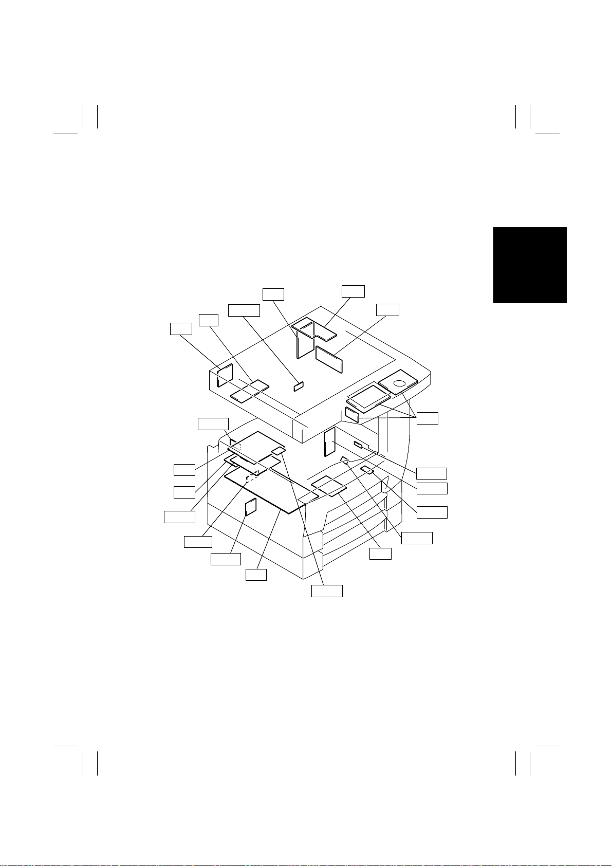
2-2. REMOVAL OF CIRCUIT BOARDS AND OTHER ELECTRICAL
COMPOMENTS
•
When removing a circuit board or other electrical component, refer to “PRECAUTIONS
FOR HANDLING THE PWBs” contained in SWITCHES ON PWBs and follow the corresponding removal procedures.
•
The removal procedures given in the following omit the removal of connectors and
screws securing the circuit board support or circuit board.
•
Where it is absolutely necessary to touch the ICs and other electrical components on the
board, be sure to ground your body.
BCR
UN2
UN3
PWB-A
PWB-I
INV
PWB-L
PWB-A
PWB-R
PU1
PU2
HGB
CCD
UN1
PWB-R
PWB-A
PWB-R
PWB-H
HV1
1171D020AE
PWB-N
D-7
Page 11
FrameMaker Ver.5.5E(PC) Di350 DIS/REASSEMBLY, ADJUSTMENT
98.12.09
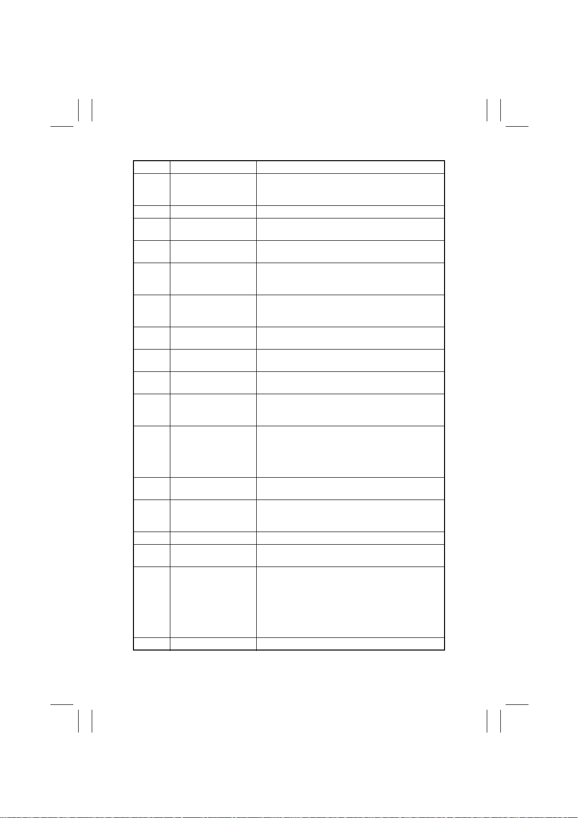
Symbol P art Name Removal Procedure
PWB-A Master Board Remo ve the Upper Cover. → Remove nine screws
PWB-A Cassette Main Board Remove the Connector Cover. → PWB-A
PWB-A Duplex Main Board Remove the Duplex Unit. → Remove the Duplex Unit
PWB-H Double Feed Detecting
Board
PWB-I Paper Size Detecting
Board
PWB-L PPM Switching Board Remove the Harness Cover. → Remove the Rear
PWB-N RAM Board Remove the Upper Cover. → Remove nine screws
PWB-R Fuser Frame Register
Board
PWB-R Pre-Transfer Guide
Plate Register Board 1
PWB-R Pre-Transfer Guide
Plate Register Board 2
PU1 Power Supply Board 1 Remove the Harness Cover. → Remove the Rear
PU2 Power Supply Board 2 Remove the Harness Cover. → Remove the Rear
HV1 High Voltage Unit Open the Side Cover. → Remove the Imaging Car-
INV Inverter Board Remove the Original Glass. → INV
BCR BCR Board Remove the Rear Left IR Cover. → Remove three
HGB HGB Board Remove the Original Glass.
CCD CCD Board See D-15.
and the MFB Box Cover. → Remove two screws and
the MFB Box Assy. → PWB-A
Rear Cover. → PWB-A
Slide out the MP Cassette. → Remove one screw and
the PWB-H Mounting Bracket Assy. → PWB-H
Remove the Harness Cover. → Remove the Rear
Cover. → Remove two screws and the PW Board
Cover. → PWB-I
Cover. → Remove one screw and the PWB-L Mounting Bracket Assy. → PWB-L
and the MFB Box Cover. → PWB-N
Remove the Fusing Unit. → Remove the rear lamp
cover. → PWB-R
Remove the Vertical Transport Unit. → Remove two
screws and two ground plates. → PWB-R
Open the Side Cover. → Remove the Imaging Car-
tridge. → Remove one screw and the PW Board
Cover. → PWB-R
Cover. → Remove the Left Cover. → Remove five
screws and the Reinforcement Bracket. → Remove
three screws and the PU1 Mounting Bracket Assy. →
PU1
Cover. → PU2
tridge. → Remove two screws and the HV1 Cover. →
HV1
screws and the Harness Cover. → BCR
→
→
Cover.
Rear Lower Cover.
→
only)
→
and the HGB Mounting Bracket Assy.
Remove the Optical Cover.
→
Remove the Shielding Plate. (U.S.A. and Canada
→
Remove one screw and the Harness Cover.
Unplug nine connectors. → Remove five screws
Remove the Rear Upper Co ver.
Remove the Right IR
→
Remove the
→
HGB
D-8
Page 12

FrameMaker Ver.5.5E(PC) Di350 DIS/REASSEMBLY, ADJUSTMENT
98.12.09
Symbol P art Name Removal Procedure
UN2 MFB Board Remove the Upper Cover. → Remove nine screws
UN3 Polygon Motor Drive
Board
and the MFB Box Cover. → UN2
Remove the PH Unit. → UN3
D-9
Page 13
FrameMaker Ver.5.5E(PC) Di350 DIS/REASSEMBLY, ADJUSTMENT
98.12.09
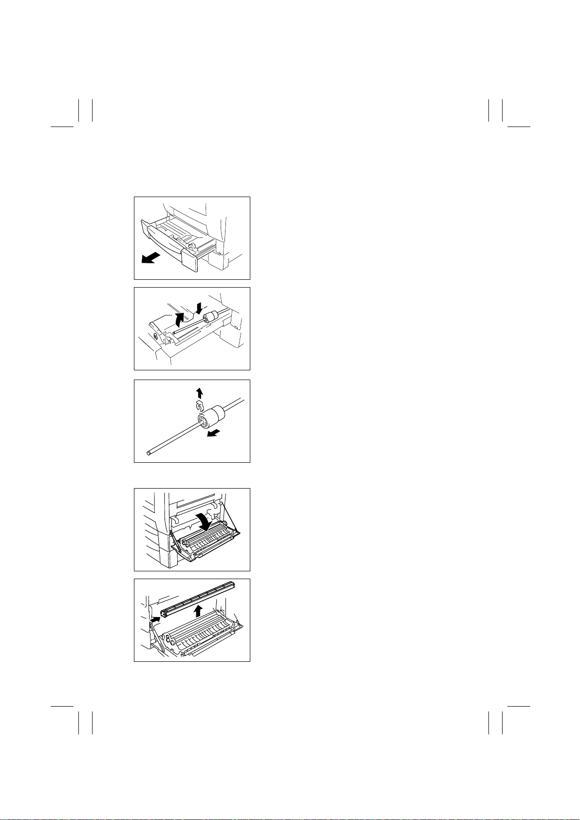
2-3. PAPER TAKE-UP/TRANSPORT SECTION
(1) Replacement of the Paper Take-Up Roll
1. Slide out the MP Cassette.
4108D033AA
2. Lock the Paper Lifting Plate.
3. Snap off one C-clip of the Paper Take-Up Roll
Assy.
4. Slide the Paper Take-Up Roll Assy to the rear so
that it can be pulled off the bushing at the front.
1167D140AA
5. Snap off one C-clip and remove and replace the
Paper Take-Up Roll.
4108D035AA
(2) Replacement of the Paper Dust Remover
1. Open the Side Cover.
1171D021AA
2. Remove the Paper Dust Remover and replace it.
1167D007AB
D-10
Page 14
FrameMaker Ver.5.5E(PC) Di350 DIS/REASSEMBLY, ADJUSTMENT
98.12.09
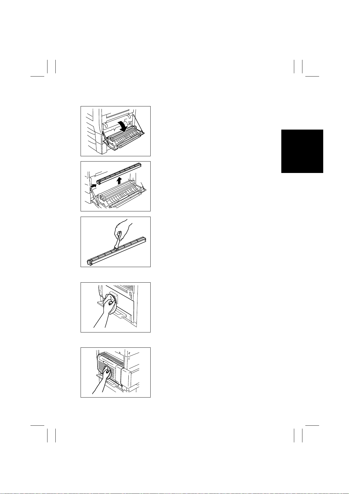
(3) Cleaning of the Paper Dust Remover
1. Open the Side Cover.
1171D021AA
2. Remove the Paper Dust Remover.
1167D007AB
3. Using a brush, whisk dust and dirt off the Paper
Dust Remover.
1167D008AB
(4) Cleaning of the Side Cover
Using a soft cloth dampened with alcohol, wipe the
Side Cover.
1171D052AB
(5) Cleaning of the Duplex Unit Cover
Using a soft cloth dampened with alcohol, wipe the
Duplex Unit Cover.
1171D051AA
D-11
Page 15
FrameMaker Ver.5.5E(PC) Di350 DIS/REASSEMBLY, ADJUSTMENT
98.12.09
2-4. OPTICAL SECTION
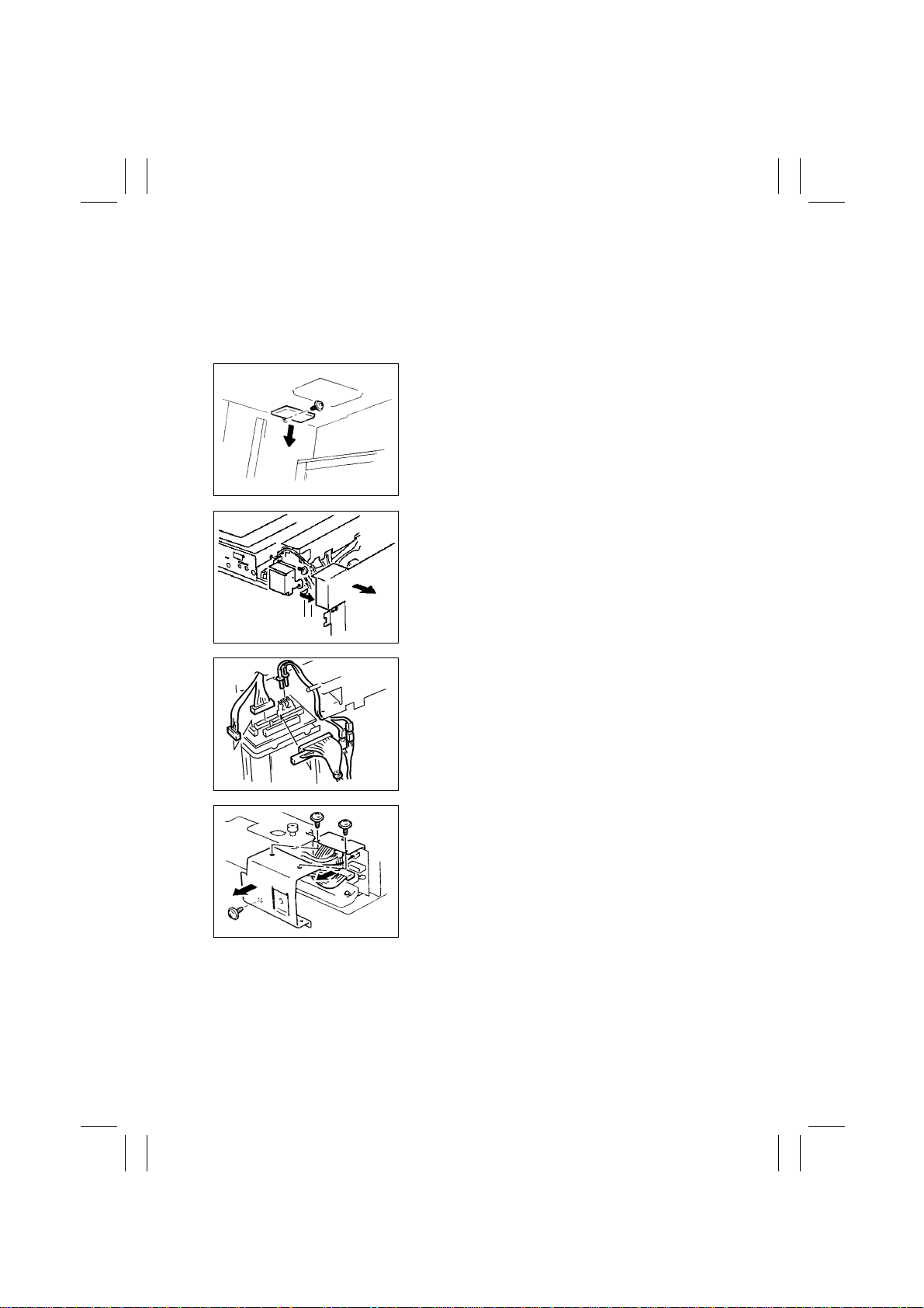
(1) Removal of the IR Unit
1. Remove the Original Cover , Front Holding Brack et, Upper F ront Left Co v er , Front Cover ,
Front Upper Cover, Rear Right IR Cover, Rear Left IR Cover, Rear Lower Cover, Rear
Upper Cover, and Front Inside Cover.
2. Remove one screw and the Motor Cover.
1171D054AA
3. Remove the Shielding Plate. (U.S.A. and Canada
only)
4. Remove one screw and the Harness Cover.
1167D149DA
1167D027AC
1167D032AC
5. Unplug eight connectors of the HGB Board.
6. Remove three screws and the Harness Cover.
7. Unplug one connector of the BCR Board.
D-12
Page 16
FrameMaker Ver.5.5E(PC) Di350 DIS/REASSEMBLY, ADJUSTMENT
98.12.09
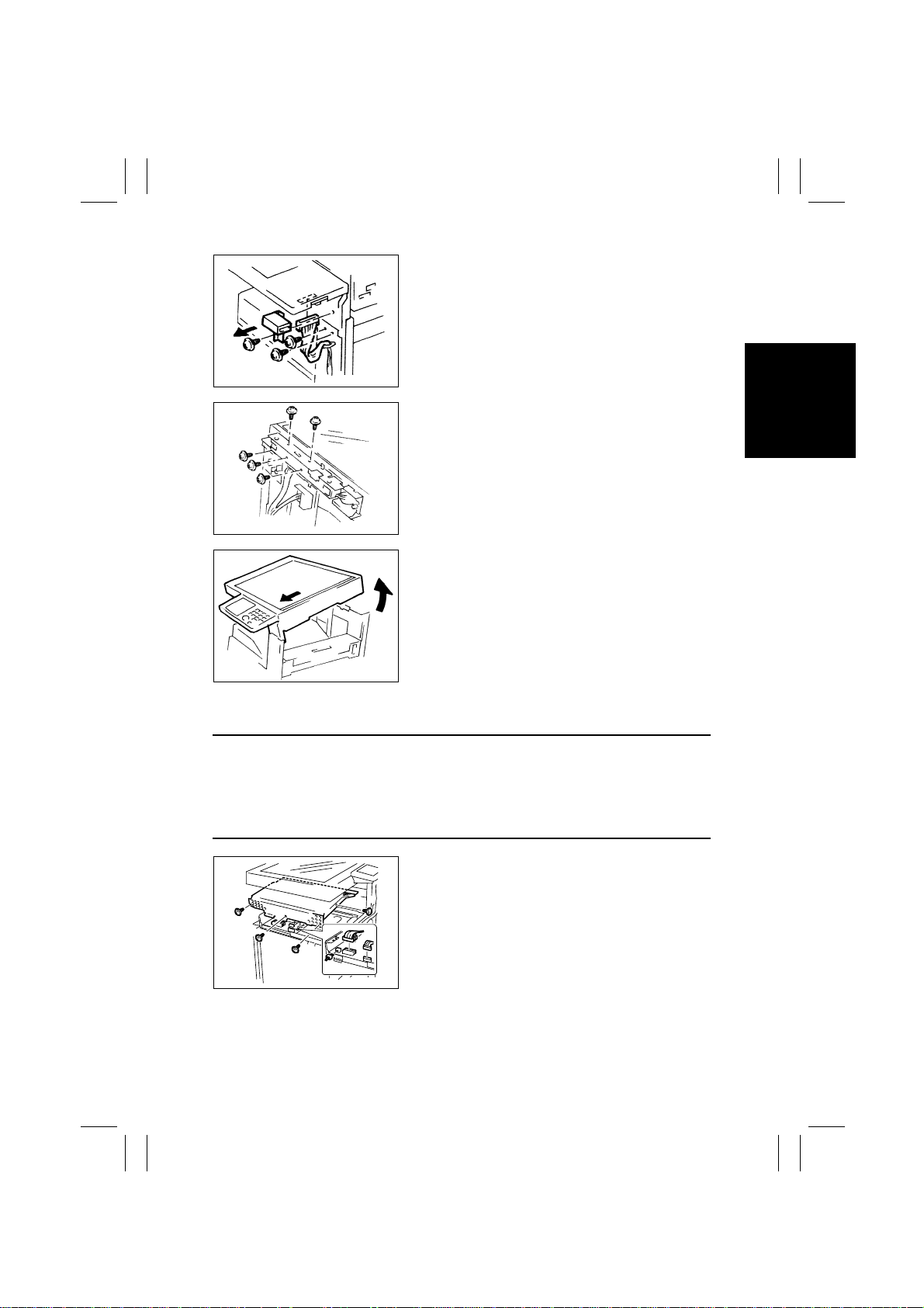
8. Remove one screw and the Total Counter Mounting Bracket Assy.
9. Unplug one connector of the Control Panel.
10. Remove two screws that secure the front end of
the frame.
1167D033AC
11. Remove five screws that secure the rear end of the
frame.
1167D059AC
12. Raise the rear end of the IR Unit and pull the unit
out toward front.
1171D053AA
(2) Removal of the PH Unit
NOTES
•
Do not place the PH Unit upside down or subject it to excessive shock.
•
Replace the PH Unit as one unit.
•
NEVER attempt to disassemble or adjust the PH Unit.
•
Whenever the PH Unit has been removed, make the following adjustments:
Edge Erase, Registration (CD, FD) (Printer), Registration (IR).
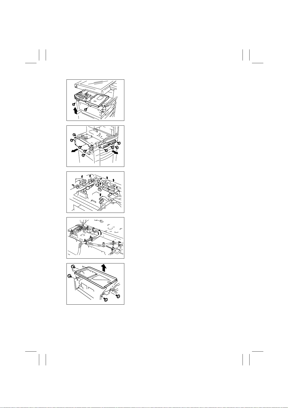
1. Remove the Upper Cover, Front Cover, Left Cover,
and Rear Cover.
2. Remove four screws and the MFB Box Cover.
3. Unplug five connectors of the MFB Board.
1167D058AE
D-13
Page 17
FrameMaker Ver.5.5E(PC) Di350 DIS/REASSEMBLY, ADJUSTMENT
98.12.09
4. Remove two screws and the MFB Box Assy.
1167D028AA
5. Remove five screws and the Reinforcement
Bracket.
6. Remove four screws and the handle.
1167D062AC
7. Unplug all connectors (13) from Master Board
PWB-A.
1167D029AC
1167D030AB
1167D012AA
8. Remove the harness from all cord clamps (12) on
the PH Base Plate.
9. Remove four screws and the PH Unit.
D-14
Page 18
FrameMaker Ver.5.5E(PC) Di350 DIS/REASSEMBLY, ADJUSTMENT
98.12.09
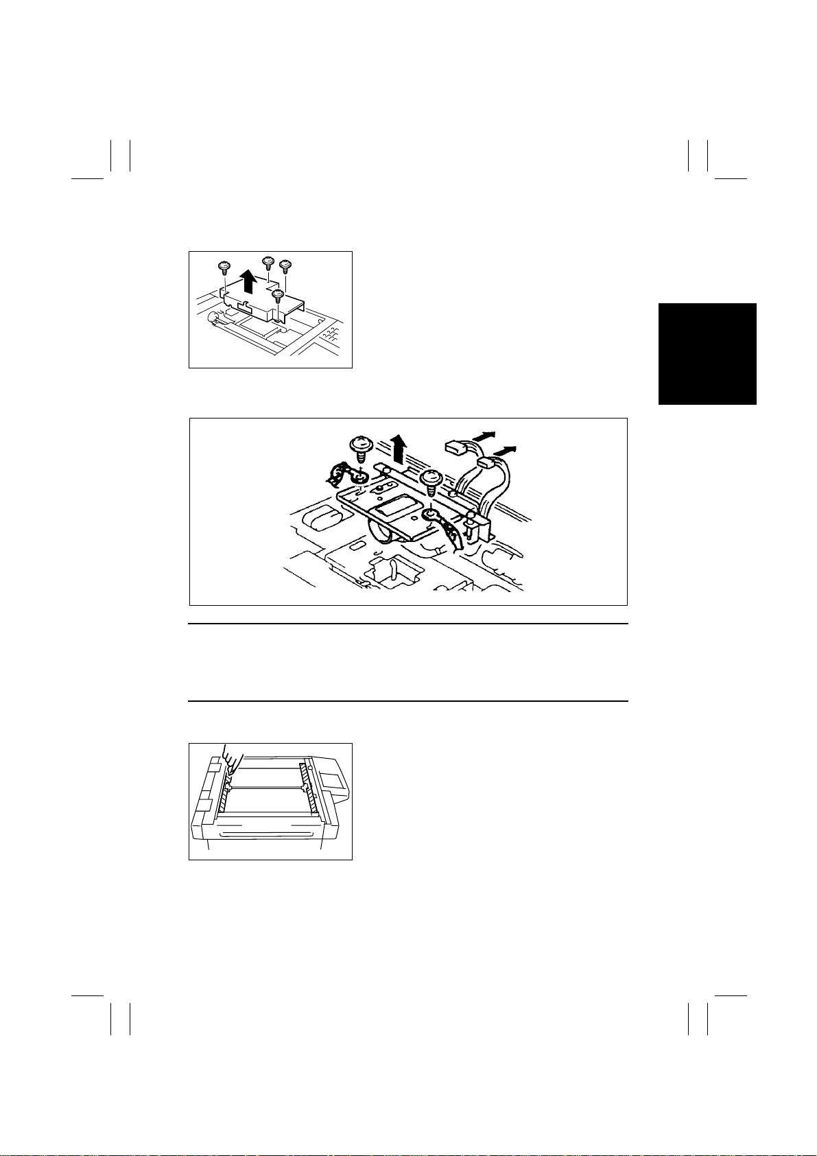
(3) Removal of the CCD Unit
1. Remove the Original Glass.
2. Remove four screws and the Cover.
1167D014AB
3. Unplug two connectors of the CCD Unit.
4. Remove two screws and the CCD Unit.
1171D055AA
NOTES
1. When removing the CCD Unit, remove only those screws and parts that are specified.
(Remove the CCD Unit as one unit.)
2. Whenever the CCD Unit has been replaced, make the following adjustment:
FD of Zoom Adjust (IR).
(4) Cleaning of the Scanner Rails/Bushings
1. Remove the Original Glass.
2. Using a soft cloth, wipe clean the Scanner Rails
and Bushings.
1167D016AB
D-15
Page 19
FrameMaker Ver.5.5E(PC) Di350 DIS/REASSEMBLY, ADJUSTMENT
98.12.09
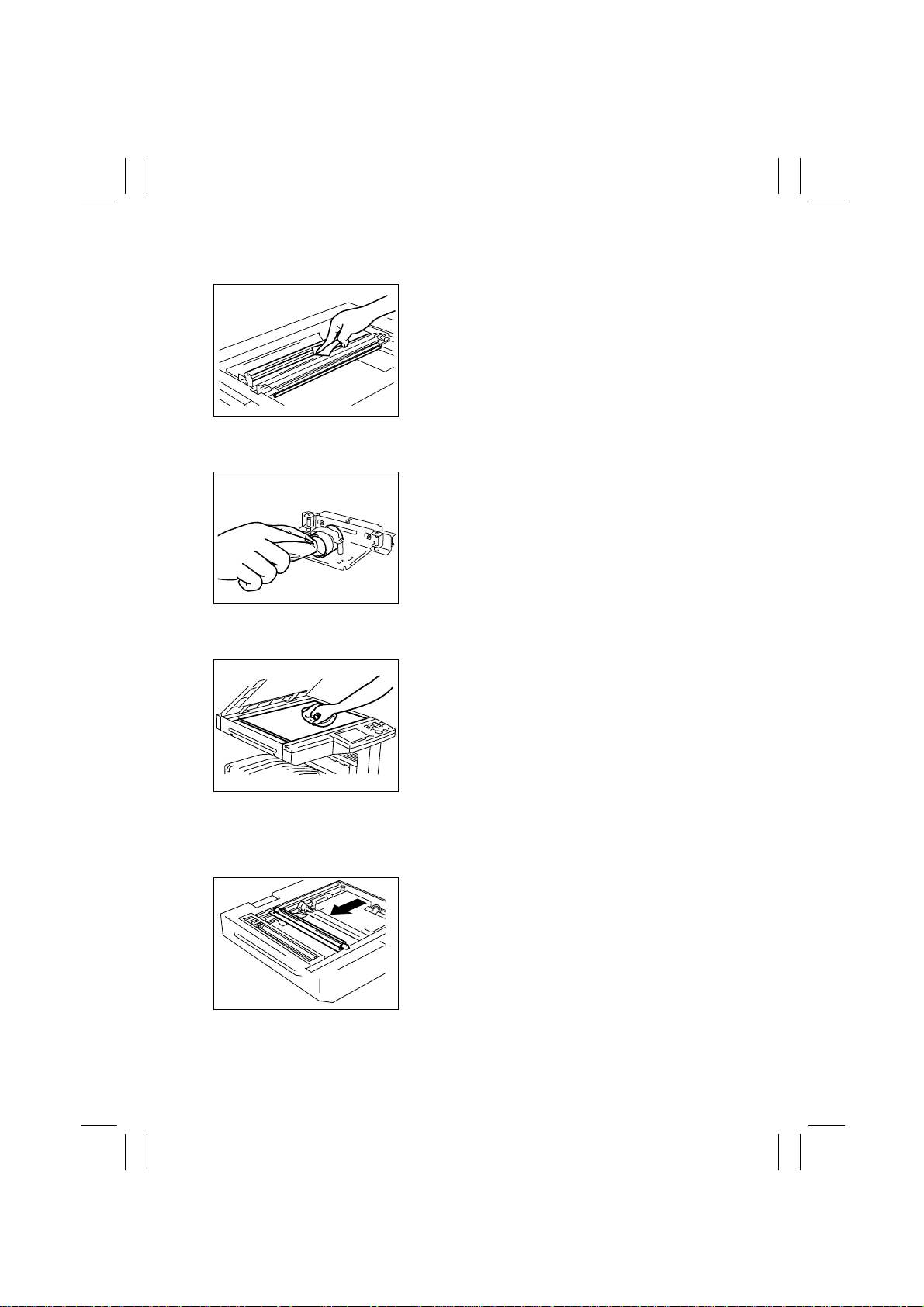
(5) Cleaning of the Mirrors
1. Remove the Original Glass.
2. Wipe clean the Mirrors with a soft cloth.
1167D017AC
(6) Cleaning of the Lens
1. Remove the CCD Unit.
2. Wipe clean the Lens with a soft cloth.
1167D018AB
(7) Cleaning of the Original Glass
Wipe clean the Original Glass with a soft cloth.
1171D050AA
(8) Removal of the Scanner
1. Remove the Original Glass.
2. Remove the Rear Holding Bracket.
3. Slide the Scanner to the position shown.
1167D039AC
D-16
Page 20
FrameMaker Ver.5.5E(PC) Di350 DIS/REASSEMBLY, ADJUSTMENT
98.12.09
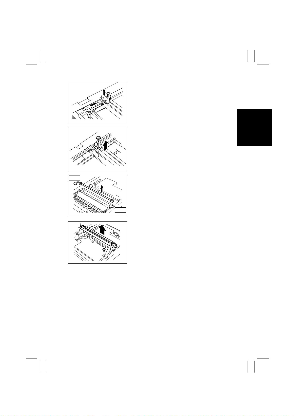
4. Remove one screw and unplug the connector of
the Exposure Lamp.
5. Remove the flat cable of the Exposure Lamp.
1167D037AC
6. Remove one screw and the Lamp Fixing Bracket.
1167D035AD
Rear
7. Slide the Exposure Lamp to the front and remove
it.
Front
1167D036AA
8. Remove two screws and the Scanner.
1167D049AB
D-17
Page 21
FrameMaker Ver.5.5E(PC) Di350 DIS/REASSEMBLY, ADJUSTMENT
98.12.09
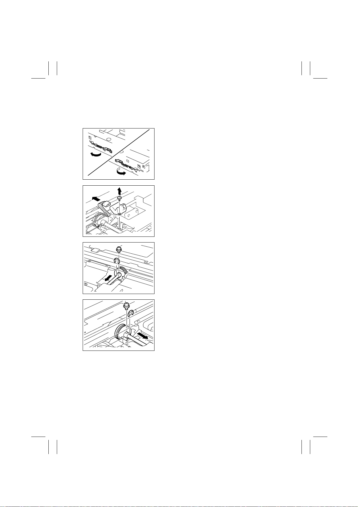
(9) Removal of the Scanner Drive Cables
1. Remove the Original Glass and ADF Glass Assy.
2. Remove the Left IR Cover.
3. Remove the Scanner.
4. Unhook the spring of the cable on the hook side,
one each at the front and in the rear.
1167D044AB
5. Remove one screw and the Original Size Detection
Sensor.
✽
Inch Areas Option.
1167D070AA
6. Snap off one E-ring and remove one mounting
screw from the front pulley and slide the pulley to
the rear.
1167D071AA
7. Snap off one E-ring and remove one mounting
screw from the rear pulley and slide the pulley to
the front.
1167D072AA
8. Remove the Scanner Drive Cable, hook end first.
D-18
Page 22
FrameMaker Ver.5.5E(PC) Di350 DIS/REASSEMBLY, ADJUSTMENT
98.12.09
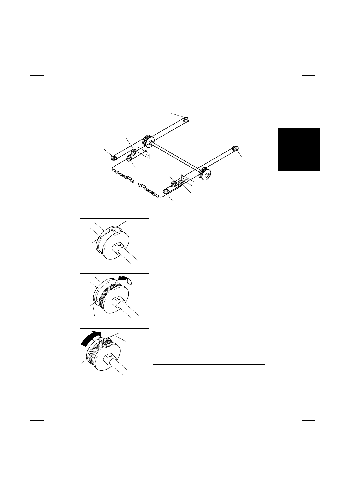
(10) Winding of the Scanner Drive Cables
Pulley H
Pulley F
Pulley E
Pulley G
Pulley B
Pulley C
Pulley A
Front
1. Position the round bead of the Scanner Drive
Cable in the pulley as shown.
Pulley D
1167D047AB
Cable on Hook End
1167D051AC
1167D052AD
Cable on
Bead End
1167D053AD
2. Wind the hook end of the Scanner Drive Cable two
turns counterclockwise from the rear side to the
front.
3. Wind the bead end of the cable four turns clockwise from the front to the rear. Then, secure the
cable with tape.
NOTE
Make sure that no part of the cable rides on the other.
D-19
Page 23
FrameMaker Ver.5.5E(PC) Di350 DIS/REASSEMBLY, ADJUSTMENT
98.12.09
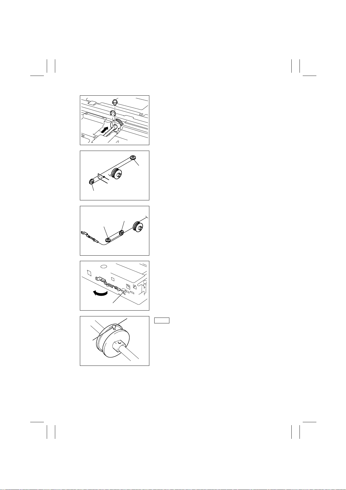
4. Slide the pulley to the front and install one mounting screw and one E-ring.
1167D073AA
5. Wind the bead end of the cable around pulley D
and pulley C, then hook the bead onto the Adjust-
Pulley D
able Anchor.
Pulley C
Pulley A
Pulley B
Cable Guide
1167D056AC
6. Wind the hook end of the cable around pulley A
and pulley B.
1167D057AC
7. Fit the hook end of the cable into the groove in the
Cable Guide and hook the spring.
1167D074AA
Rear
8. Position the round bead of the Scanner Drive
Cable in the pulley as shown.
1167D051AC
D-20
Page 24
FrameMaker Ver.5.5E(PC) Di350 DIS/REASSEMBLY, ADJUSTMENT
98.12.09
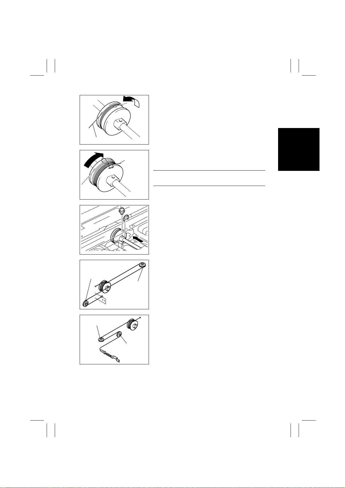
9. Wind the hook end of the cable two turns counterclockwise from the front to the rear.
Cable on Hook End
Pulley G
1167D054AD
Cable on
Bead End
1167D055AD
1167D075AA
Pulley H
1167D076AA
10. Wind the bead end of the cable four turns clockwise from the rear to the front. Then, secure the
cable with tape.
NOTE
Make sure that no part of the cable rides on the other.
11. Slide the pulley toward the rear and install one
mounting screw and one E-ring.
12. Wind the bead end of the cable around pulley H
and pulley G and hook the bead onto the Adjustable Anchor.
Pulley E
13. Wind the hook end of the cable around pulley E
and pulley F.
Pulley F
1167D078AA
D-21
Page 25
FrameMaker Ver.5.5E(PC) Di350 DIS/REASSEMBLY, ADJUSTMENT
98.12.09
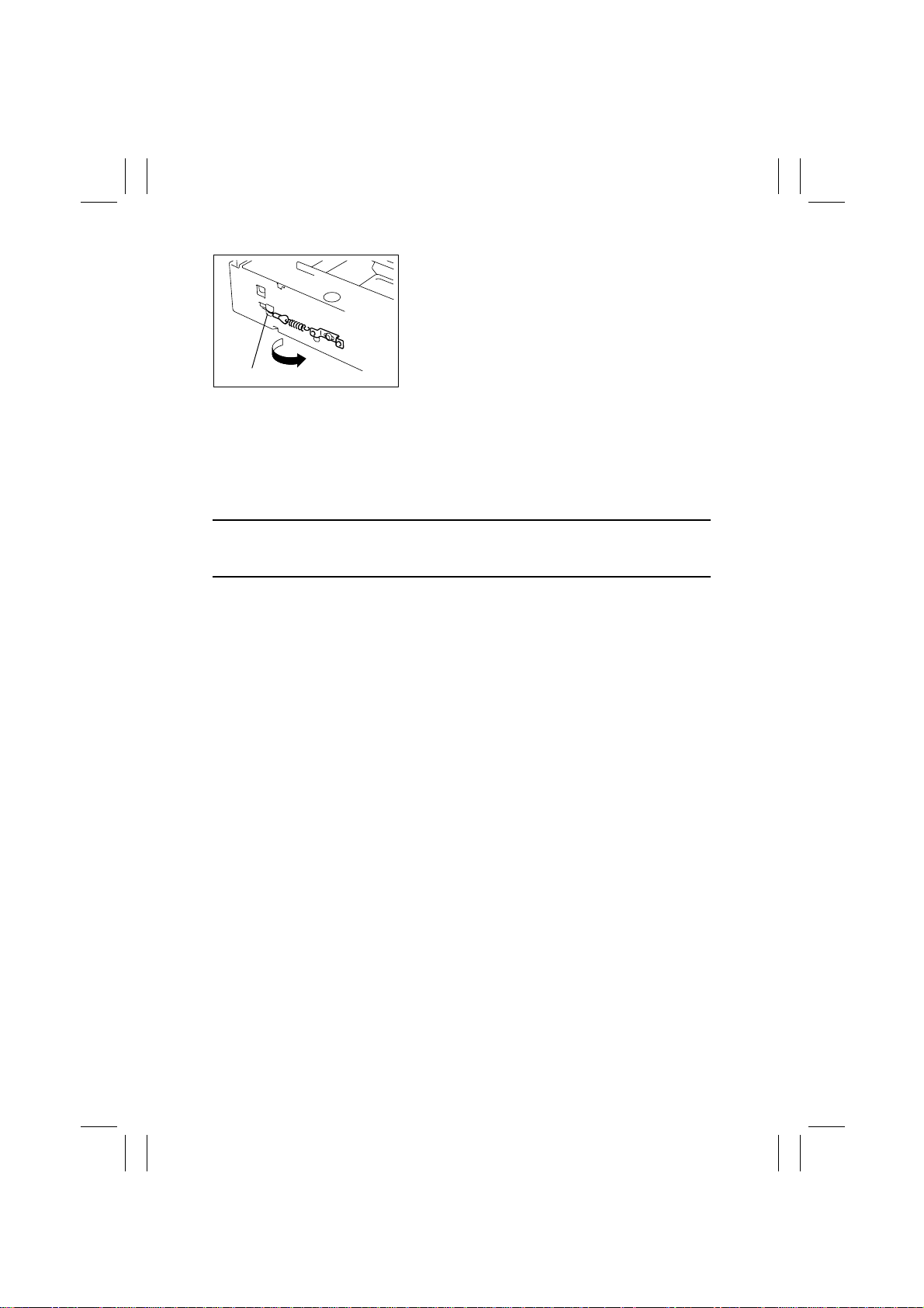
14. Fit the hook end of the cable into the groove in the
Cable Guide and hook the spring.
Cable Guide
15. Peel off the tape from the pulleys at the front and rear.
16. Mount the Scanner.
17. Mount the Original Size Detection Sensor.
18. Reinstall the Left IR Cover.
19. Reinstall the Original Glass and ADF Glass Assy.
20. Perform the Focus-Positioning of the Scanner and 2nd/3rd Mirrors Carriage.
(For details, see ADJUSTMENT.)
1167D077AA
NOTE
Whenever the Scanner Drive Cables have been removed, be sure to make the following
adjustment: CD of Zoom Adjust (IR).
D-22
Page 26
FrameMaker Ver.5.5E(PC) Di350 DIS/REASSEMBLY, ADJUSTMENT
98.12.09
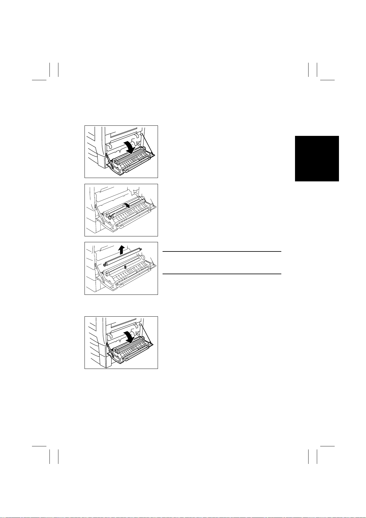
2-5. IMAGE TRANSFER SECTION
(1) Removal of the Image Transfer Roller
1. Open the Side Cover.
1167D006AD
2. Raise the Image Transfer Guide Plate.
1167D061AA
3. Remove the Image Transfer Roller and replace it.
NOTE
Do not touch the surface of the Image Transf er Roller
directly with bare hands.
4108D027AA
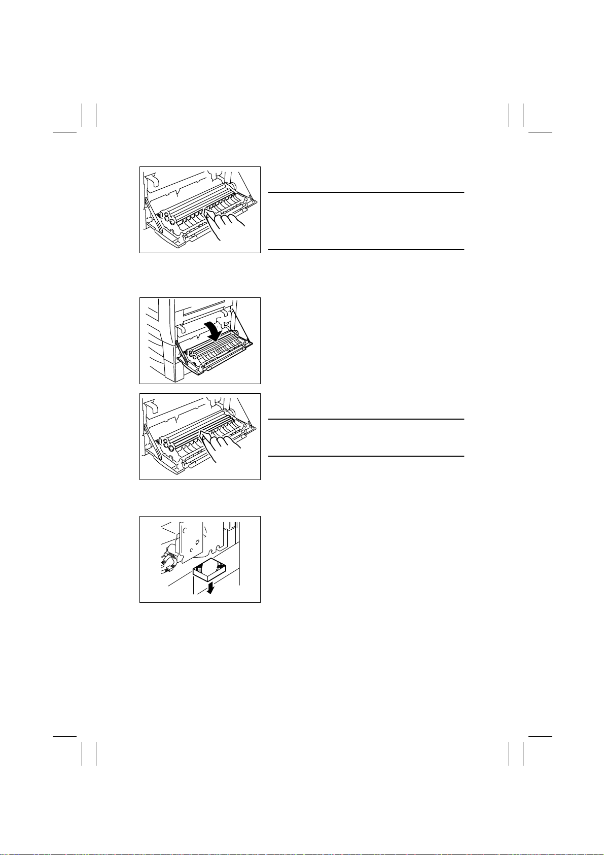
(2) Cleaning of the Comb Electrode
1. Open the Side Cover.
1171D021AA
D-23
Page 27
FrameMaker Ver.5.5E(PC) Di350 DIS/REASSEMBLY, ADJUSTMENT
98.12.09
2. Using a soft cloth dampened with alcohol, wipe the
Comb Electrode.
NOTES
•
Make sure the alcohol does not touch the surface of
the Image Transfer Roller.
•
When wiping the Comb Electrode, make sure the
1167D009AA
cloth is not caught by the ends of the combs.
(3) Cleaning of the Pre-Image Transfer Guide Plate
1. Open the Side Cover.
1171D021AA
2. Using a soft cloth dampened with alcohol, wipe the
NOTE
Make sure the alcohol does not touch the surface of
the Image Transfer Roller.
1167D010AA
(4) Replacement of the Ozone Filter
1. Remove the Rear Lower Cover.
2. Pull out the Ozone Filter and replace it.
1171D022AC
Pre-Image Transfer Guide Plate.
D-24
Page 28
FrameMaker Ver.5.5E(PC) Di350 DIS/REASSEMBLY, ADJUSTMENT
98.12.09
2-6. DEVELOPING SECTION
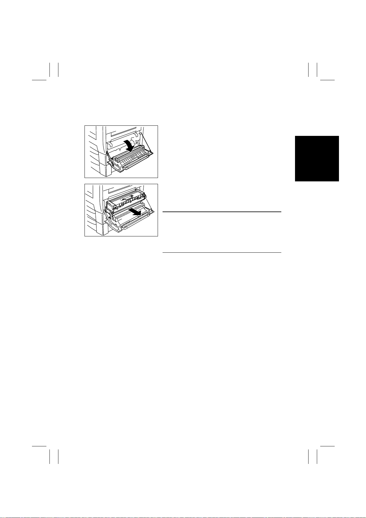
(1) Removal of the Imaging Cartridge
1. Open the Side Cover.
1171D021AA
2. Holding onto the green handles, slide the Imaging
Cartridge part of the way out.
3. Then grasp the handle on top of the cartridge and
pull the cartridge out.
NOTE
When installing the Imaging Cartridge, push it all the
1171D023AA
way into the machine.
If the cartridge is not properly installed, the PC Drum
protective shutter of the cartridge may not be opened
or may even be damaged.
D-25
Page 29
FrameMaker Ver.5.5E(PC) Di350 DIS/REASSEMBLY, ADJUSTMENT
98.12.09
2-7. FUSING SECTION
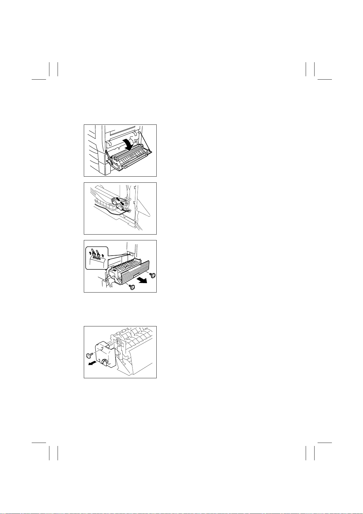
(1) Removal of the Fusing Unit
1. Open the Side Cover.
1171D021AA
2. Remove the Front Cover.
3. Unplug one connector at the front.
1167D020AB
4. Open the Exit Cover and unplug two connectors in
the rear.
5. Close the Exit Cover and remove two screws and
the Fusing Unit.
1167D021AB
(2) Removal of the Fusing Roller Heater Lamp, Fusing Right Roller, Fusing Left
Roller , Fusing Roller Thermistor , Fusing Roller Thermostat, and Fusing Roller
Heater Lamp Fuse
1. Open the Exit Cover.
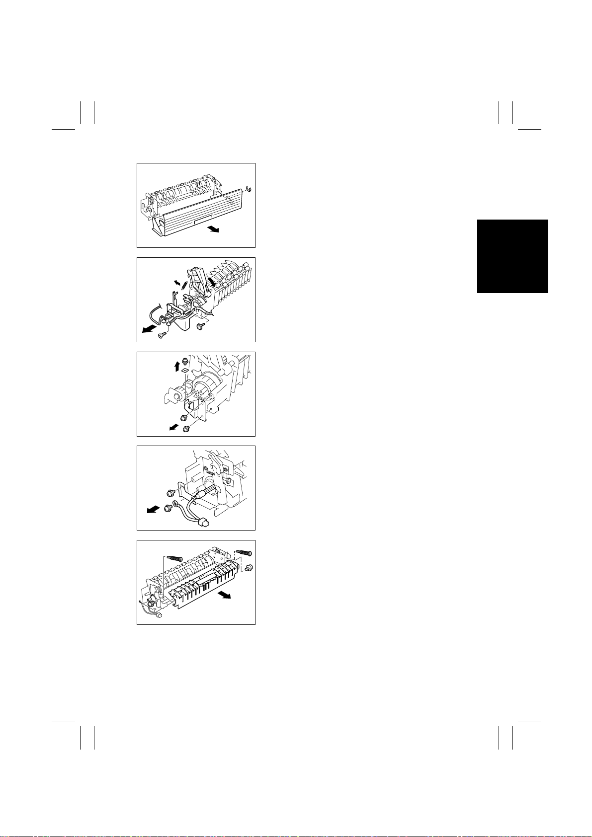
2. Remove one screw and the Fusing Front Cover.
1171D036AA
D-26
Page 30
FrameMaker Ver.5.5E(PC) Di350 DIS/REASSEMBLY, ADJUSTMENT
98.12.09
3. Snap off one E-ring and remove the Exit Cover.
1171D037AA
4. Unhook one spring to free the Idle Lever.
5. Remove two harnesses.
6. Remove two screws and the Rear Cover.
1171D038AA
7. Remove three screws and the rear Lamp Holder.
1171D039AA
1171D041AA
1171D043AA
8. Remove one screw and the front Lamp Holder.
9. Remove one screw and the Fusing Roller Heater
Lamp.
10. Remove two screws and the Fusing Rear Guide
Assy.
11. Remove two pressure springs.
D-27
Page 31
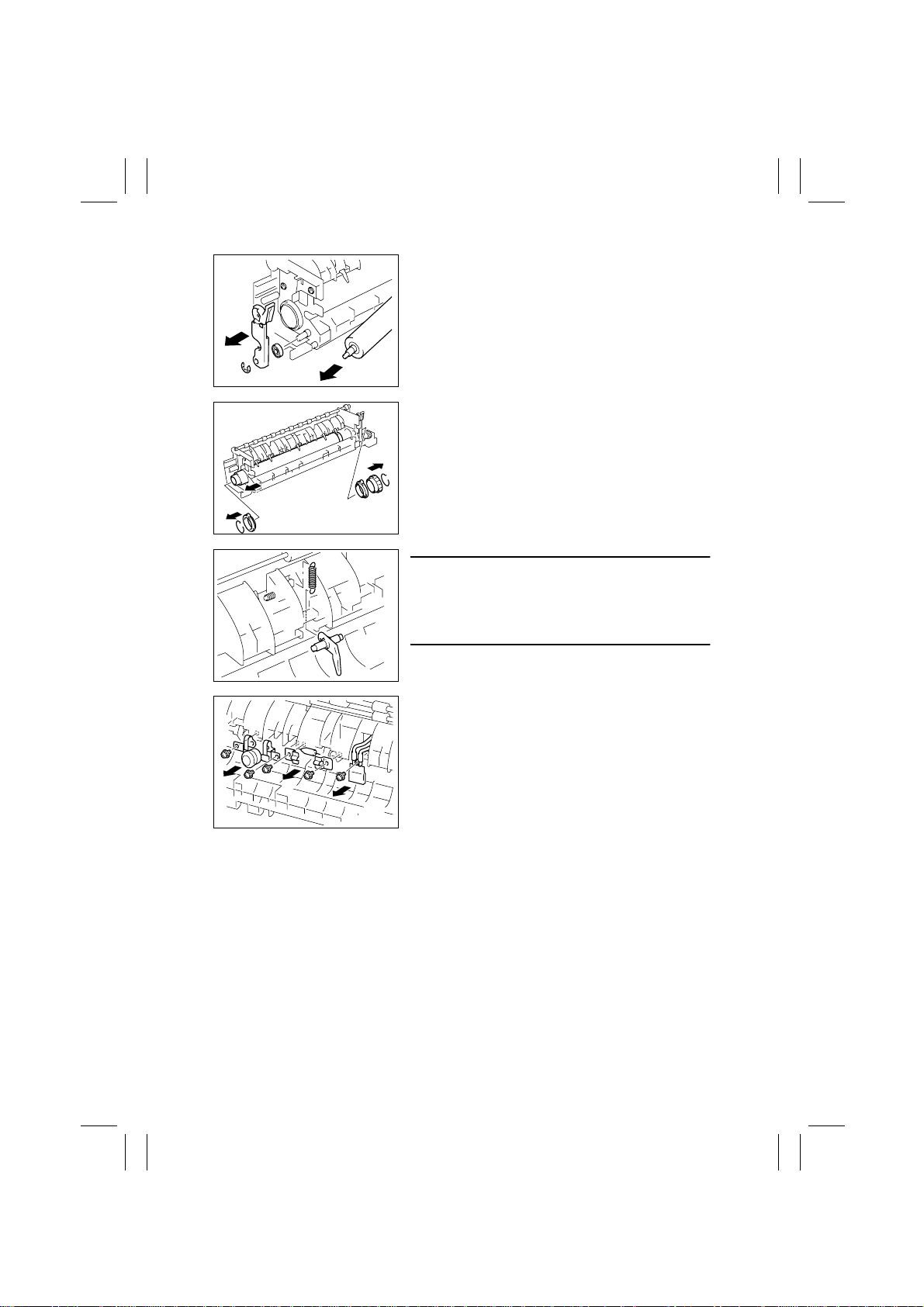
FrameMaker Ver.5.5E(PC) Di350 DIS/REASSEMBLY, ADJUSTMENT
98.12.09
12. Snap off one E-ring and remove the front Misfeed
Clearing Lever Assy and bearing.
13. Remove the Fusing Right Roller.
1171D044AA
14. Snap off two retaining rings.
15. Remove one gear and two bushings.
16. Remove the Fusing Left Roller.
1171D045AA
NOTE
When the Fusing Left Roller is removed, it can cause
the spring to come off the Separator Finger. After the
Fusing Left Roller has later been reinstalled, be sure to
hook the spring onto the Separator Finger.
1171D046AA
1171D047AA
17. Remove one screw and the Fusing Roller Thermistor.
18. Remove two screws and the Fusing Roller Heater
Lamp Fuse.
19. Remove two screws and the Fusing Roller Thermostat.
D-28
Page 32
FrameMaker Ver.5.5E(PC) Di350 DIS/REASSEMBLY, ADJUSTMENT
98.12.09
3 ADJUSTMENT
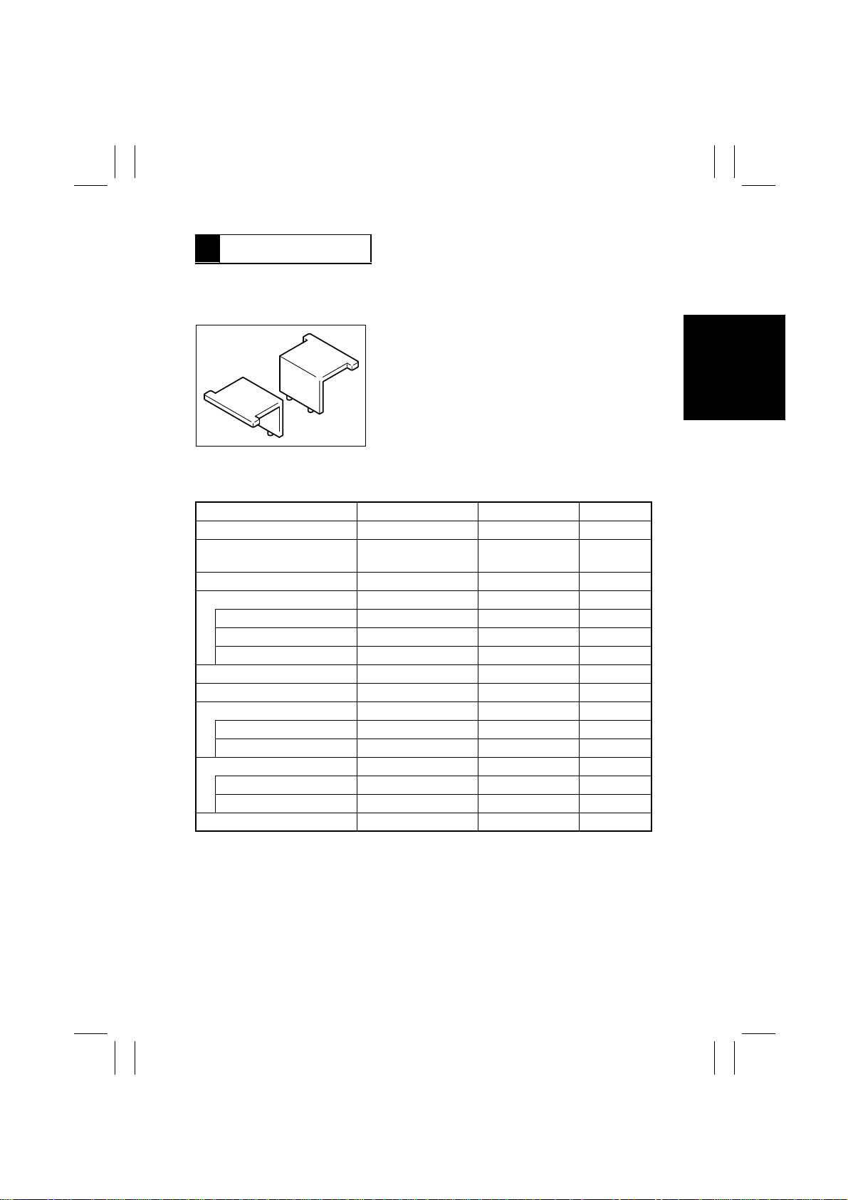
3-1. ADJUSTMENT JIGS AND TOOLS USED
1. Scanner/Mirrors Carriage Positioning Jigs
1167D108AA
3-2. ADJUSTMENT REQUIREMENT LIST
Adjustment Item Requirements Adjustment Point Ref. Page
Touch Panel Adj. Automatically adjusted Control Panel D-32
Original Size Detecting Sensor
Adjustmen t
Loop Adjustment —
Edge Erase
Leading —
Trailing —
Right/Left —
Registration (CD) (Printer) 10 ± 2.0 mm
Registration (FD) (Printer)
Registration (IR)
CD
FD
Zoom Adjust (IR)
CD 200 ±1.0 mm
FD 300 ±1.5 mm
IR-Erasure Width —
↑↑
↑
↑
↑
↑
↑
↑↑
↑↑
↑↑
↑
↑
↑
D-33
D-34
D-35
D-36
D-37
D-38
D-40
D-42
D-44
D-46
D-48
D-50
D-29
Page 33
FrameMaker Ver.5.5E(PC) Di350 DIS/REASSEMBLY, ADJUSTMENT
98.12.09
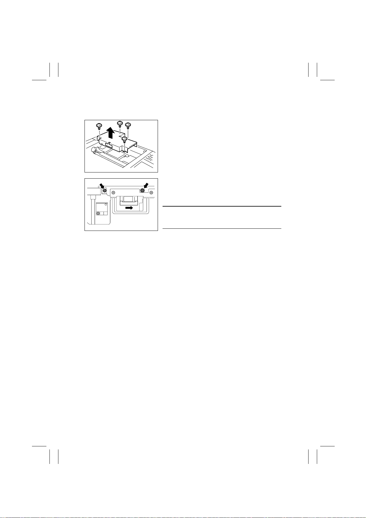
3-3. ADJUSTMENT OF BELT TENSION
•
Adjustment of the Scanner Motor Timing Belt
1. Remove the Original Glass.
2. Remove four screws and the Cover.
1167D014AB
3. Loosen the two screws that secure the Scanner
Motor. Using a bar tension gage, pull the motor to
the right with a tension of 1000 g ±50 g and, at the
same time, tighten the mounting screws.
NOTE
After the adjustment, turn the timing belt to check that
1167D109AB
the belt teeth are in mesh with the pulley grooves.
D-30
Page 34
FrameMaker Ver.5.5E(PC) Di350 DIS/REASSEMBLY, ADJUSTMENT
98.12.09
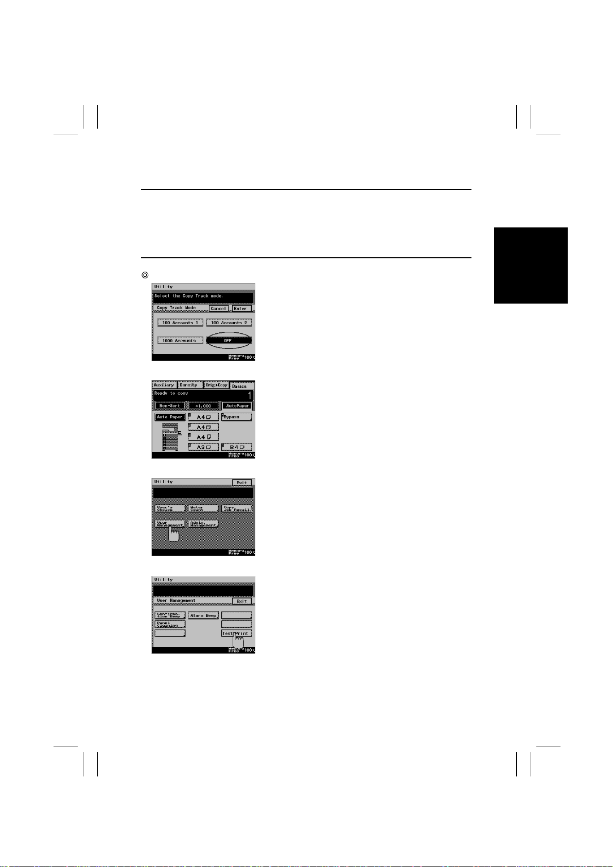
3-4. TEST PRINT
NOTES
This function is used to make the following electrical and image adjustments:
•
Registration (CD) (Printer)
•
Registration (FD) (Printer)
•
Registration (IR)
•
Zoom Adjust (IR)
Adjustment Procedure
1. Check that “Copy Track Mode” of “Copy Track”
under “Admin. Management” available from “Utili ty”
is “OFF.”
1171D026CA
2. Select the paper source for the test print.
1171D027CA
3. Press the Utility key on the control panel and touch
[User Management].
1171D028CA
1171D029CA
4. Touch [Test Print] to produce a test pattern.
D-31
Page 35
FrameMaker Ver.5.5E(PC) Di350 DIS/REASSEMBLY, ADJUSTMENT
98.12.09
3-5. ELECTRICAL/IMAGE ADJUSTMENT
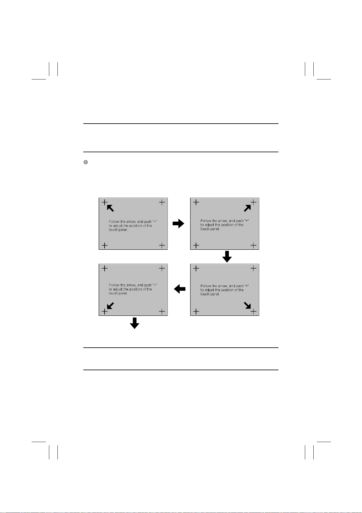
(1) Touch Panel Adj.
NOTE
Make this adjustment after either of the following procedures have been performed:
•
Memory Clear
•
Control Panel replacement
Adjustment Procedure
1. Call the Initial mode to the screen. (For details, see SWITCHES ON PWBs, TECH.
REP. SETTINGS.)
2. Touch [Touch Panel Adj.].
12
1171D056CA
4
“Initial” Screen
3. Touch + on screen 1.
NOTE
At this time, ensure that the very center of “+
similar device.
4. Touch + on screen 2.
5. Touch + on screen 3.
6. Touch + on screen 4.
D-32
1171D057CA
3
1171D058CA1171D059CA
is touched using the tip of a ballpoint pen or
”
Page 36
FrameMaker Ver.5.5E(PC) Di350 DIS/REASSEMBLY, ADJUSTMENT
98.12.09
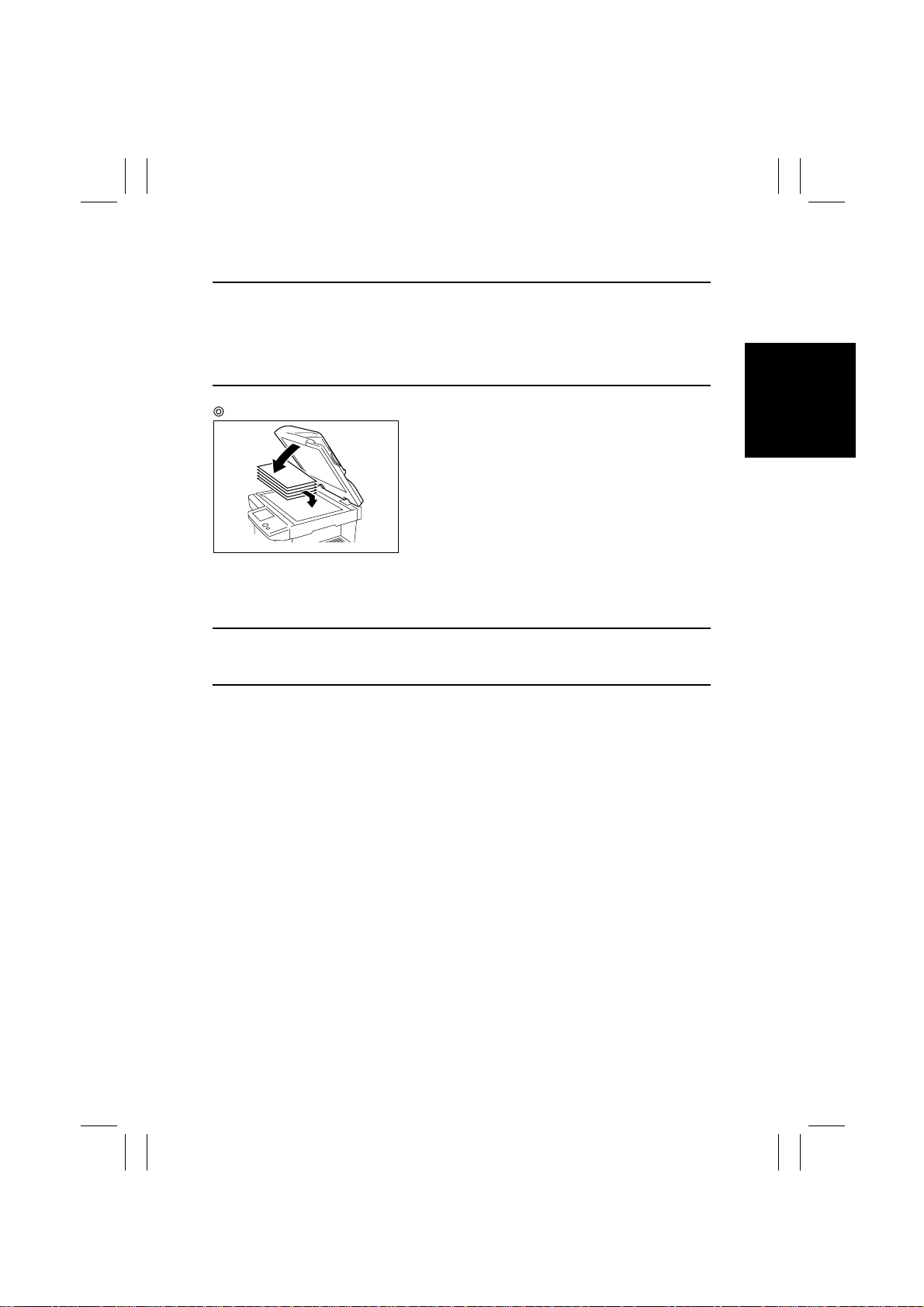
(2) Original Size Detecting Sensor Adjustment (F7-1)
NOTE
Make this adjustment after any of the following procedures have been performed:
•
Memory Clear
•
A faulty original size detection occurs
•
Replacement of the CCD Unit and Scanner parts (including the Exposure Lamp)
•
RAM Board replacement
Adjustment Procedure
1167D110AB
2. Call the Tech. Rep. mode to the screen.
3. Touch [Function] to call the Function menu.
4. Touch F7-1 Original Size Detecting Sensor Adjustment.
5. Press the Start key to run the Original Size Detecting Sensor Adjustment function.
1. Stack five sheets of blank A3 or 11” × 17” paper on
the Original Glass and lower the Original Cover.
NOTE
The Start key remains lit up orange while this function is being run and lights up green as
soon as the sequence is completed.
D-33
Page 37
FrameMaker Ver.5.5E(PC) Di350 DIS/REASSEMBLY, ADJUSTMENT
98.12.09
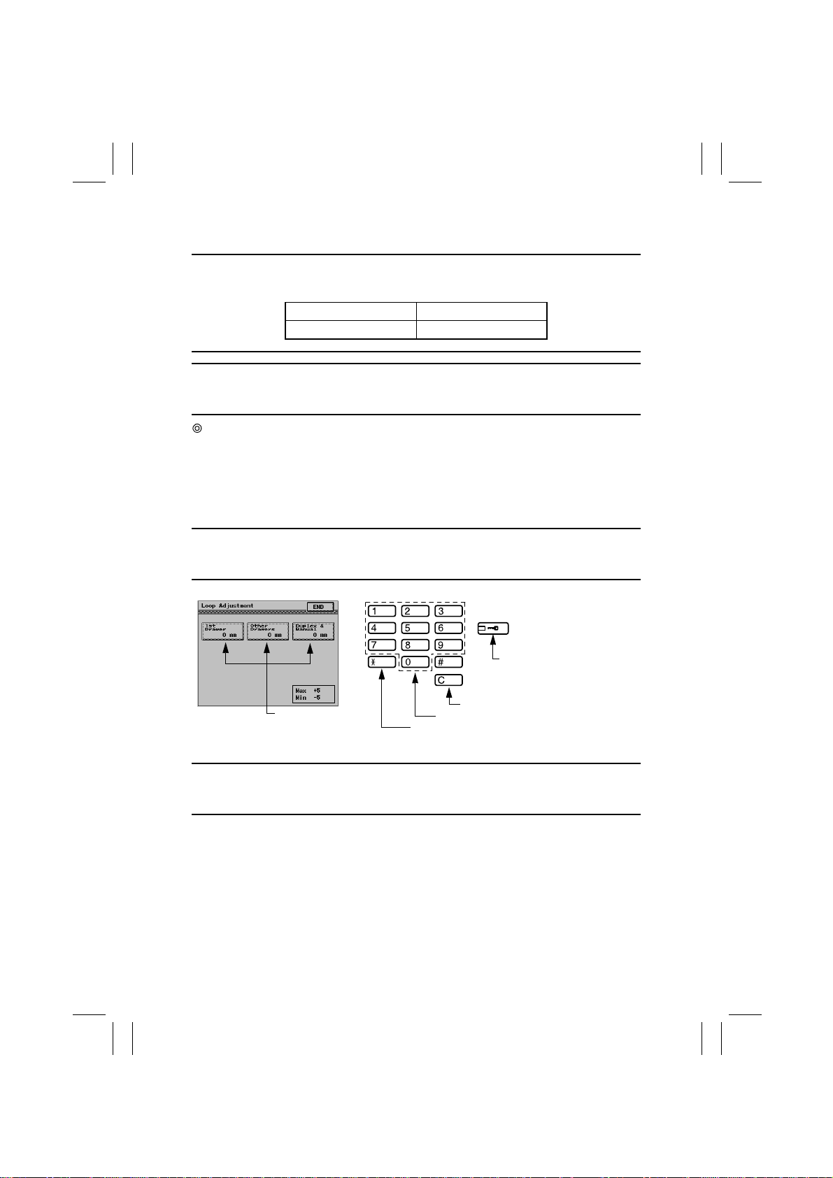
(3) Loop Adjustment
Requirement
Adjust so that a correct loop is formed before the Synchronizing Rollers when paper is fed
through.
Adjust Mode Setting Value
Loop Adjustment -5 to +5
NOTE
This adjustment is to be made when any of the following symptoms occurs: variations in the
amount of print leading edge void, paper skew, and misfeed.
Adjustment Procedure
1. Call the Tech. Rep. mode to the screen.
2. Touch [Tech. Rep. Choice], then [Printer].
3. Touch [Loop Adjustment] to enter the Loop Adjustment mode.
4. Select the paper source for which the adjustment is to be made.
5. Press the Clear key to clear the current setting.
6. Enter the new setting value from the 10-Key Pad.
Setting Instructions
Change the setting value as necessary until there are no variations in the amount of void
image along the leading edge, skewed feeding, dog-ear, or misfeed.
Use to change the + or - sign.
1171D030CA
Setting Value
Use to change the + or - sign.
Use to clear setting value.
Use to enter setting value.
1171D061CA
7. Touch the [END] key to validate the setting value.
Caution
Be sure to touch the END key before returning to normal operation mode. If the Panel
Reset Key is used, the previous setting remains valid.
8. Perform the same steps to adjust for the other paper sources.
D-34
Page 38
FrameMaker Ver.5.5E(PC) Di350 DIS/REASSEMBLY, ADJUSTMENT
98.12.09
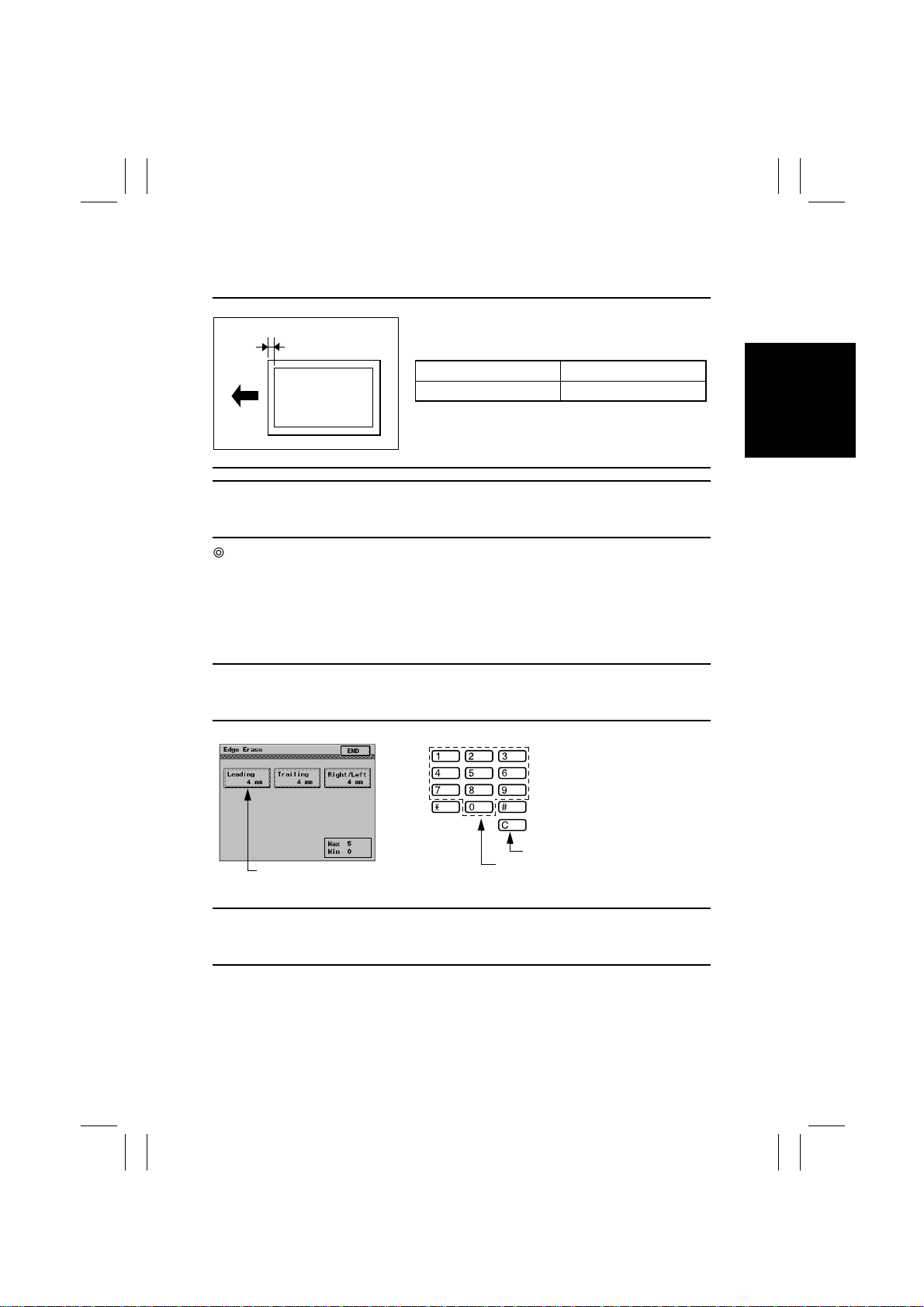
(4) Edge Erase
1. Leading
Requirement
A
Adjust so that the erase width on the leading edge falls
within the range of 0 to 5 mm.
Adjust Mode Setting Range
Edge Erase/Leading 0 to 5
1171D003AA
NOTE
This adjustment must be made when the PH Unit has been replaced and after Registration
(CD/FD) (Printer) has been made.
Adjustment Procedure
1. Call the Tech. Rep. mode to the screen.
2. Touch [Tech. Rep. Choice], then [Printer].
3. Touch [Edge Erase] and then [Leading] to enter the Leading Edge Erase adjustment
mode.
4. Press the Clear key to clear the current setting.
5. Enter the new setting value from the 10-Key Pad.
Setting Instructions
To make the edge erase width smaller, decrease the setting value.
To make the edge erase width greater, increase the setting value.
Use to clear setting value.
Setting Value
1171D031CA
Use to enter setting value.
1167D069AA
6. Touch the [END] key to validate the setting value.
Caution
Be sure to touch the END key before returning to normal operation mode. If the Panel
Reset Key is used, the previous setting remains valid.
D-35
Page 39
FrameMaker Ver.5.5E(PC) Di350 DIS/REASSEMBLY, ADJUSTMENT
98.12.09
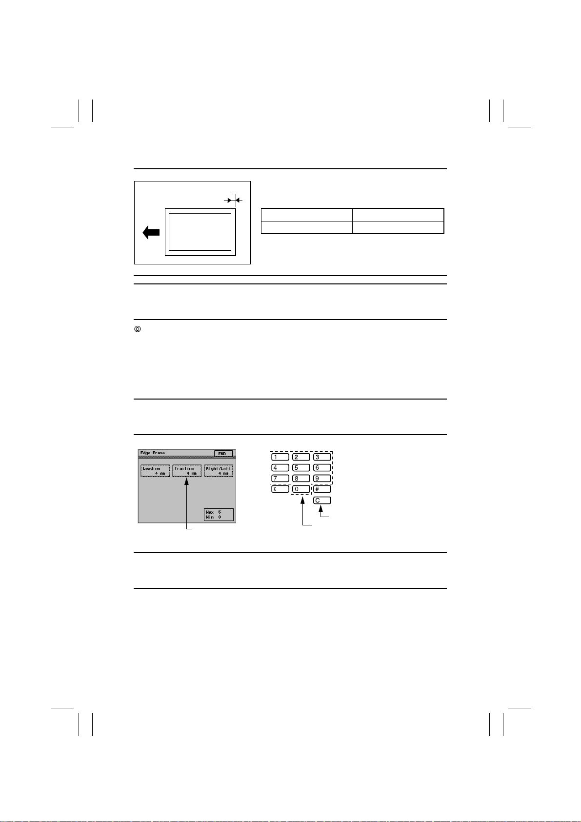
2. Trailing
Requirement
Adjust so that the erase width on the trailing edge falls
A
within the range of 0 to 5 mm.
Adjust Mode Setting Range
Edge Erase/Trailing 0 to 5
1171D004AA
NOTE
This adjustment must be made when the PH Unit has been replaced and after Registration
(CD/FD) (Printer) has been made.
Adjustment Procedure
1. Call the Tech. Rep. mode to the screen.
2. Touch [Tech. Rep. Choice], then [Printer].
3. Touch [Edge Erase] and then [Trailing] to enter the Trailing Edge Erase adjustment
mode.
4. Press the Clear key to clear the current setting.
5. Enter the new setting value from the 10-Key Pad.
Setting Instructions
To make the edge erase width smaller, decrease the setting value.
To make the edge erase width greater, increase the setting value.
Use to clear setting value.
1171D031CA
Setting Value
Use to enter setting value.
1167D069AA
6. Touch the [END] key to validate the setting value.
Caution
Be sure to touch the END key before returning to normal operation mode. If the Panel
Reset Key is used, the previous setting remains valid.
D-36
Page 40

FrameMaker Ver.5.5E(PC) Di350 DIS/REASSEMBLY, ADJUSTMENT
98.12.09
3. Right/Left
Requirement
Adjust so that the erase width on the right/left edge
falls within the range of 0 to 5 mm.
A
Adjust Mode Setting Range
Edge Erase/Right/Left 0 to 5
A
1171D005AA
NOTE
This adjustment must be made when the PH Unit has been replaced and after Registration
(CD) (Printer) have been made.
Adjustment Procedure
1. Call the Tech. Rep. mode to the screen.
2. Touch [Tech. Rep. Choice], then [Printer].
3. Touch [Edge Erase] and then [Right/Left] to enter the Right/Left Edge Erase adjustment
mode.
4. Press the Clear key to clear the current setting.
5. Enter the new setting value from the 10-Key Pad.
Setting Instructions
To make the edge erase width smaller, decrease the setting value.
To make the edge erase width greater, increase the setting value.
Use to clear setting value.
1171D031CA
Setting Value
Use to enter setting value.
1167D069AA
6. Touch the [END] key to validate the setting value.
Caution
Be sure to touch the END key before returning to normal operation mode. If the Panel
Reset Key is used, the previous setting remains valid.
D-37
Page 41
FrameMaker Ver.5.5E(PC) Di350 DIS/REASSEMBLY, ADJUSTMENT
98.12.09
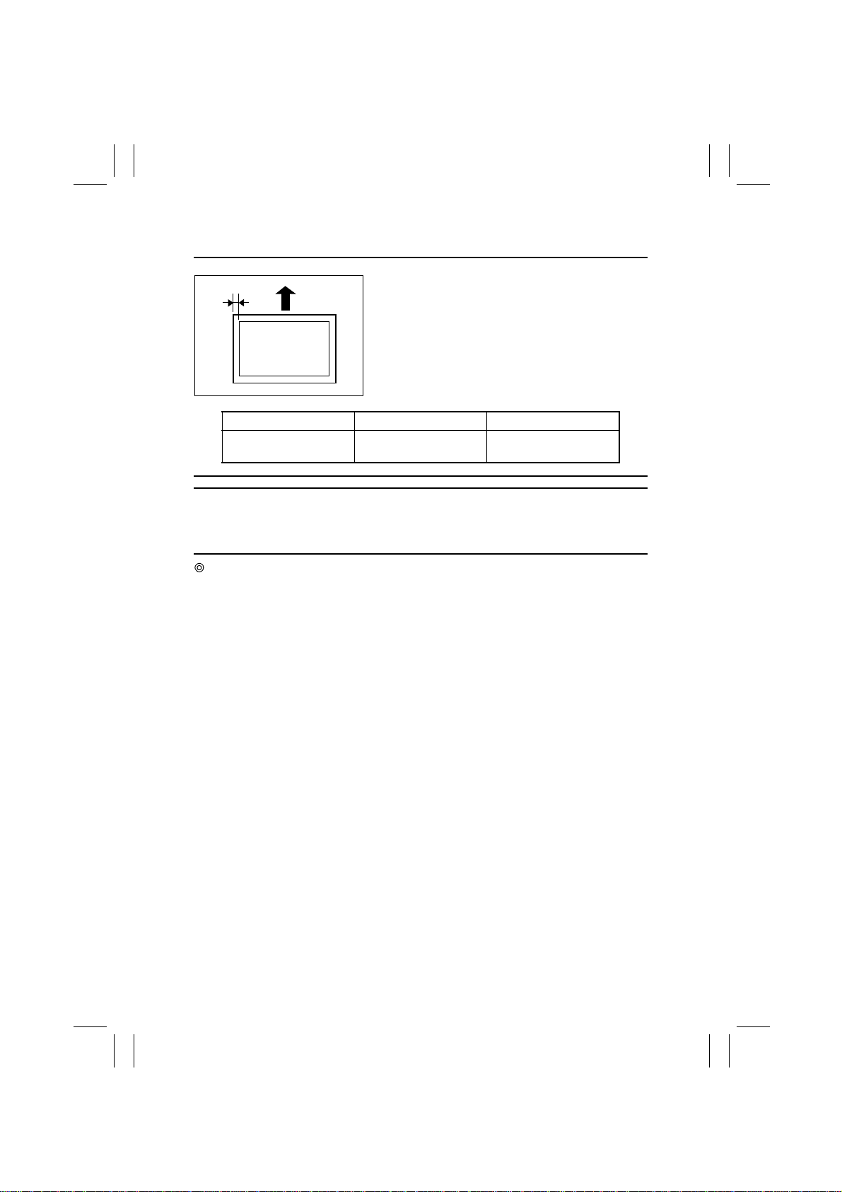
(5) Registration (CD) (Printer)
Requirement
A
1171D006AA
Specification Adjust Mode Setting Range
1-Sided: 10 ±2.0 mm
2-Sided: 10 ±3.0 mm
NOTE
This adjustment must be made when the PH Unit has been replaced and, for 2-sided, af ter
Registration (CD) (Printer) for each paper source for 1-sided and Registration (FD) (Printer)
have been made.
Adjustment Procedure
1. Produce a test pattern. (For details, see 3-4. TEST PRINT.)
2. 1-Sided: Check to see if width A on the test pattern meets the specifications.
2-Sided: Using the test pattern output as the original, make an ordinary 2-sided copy.
Check to see if width A on the second side of the 2-sided copy meets the
specifications.
If width A falls outside the specified range, perform these steps to make the adjustment.
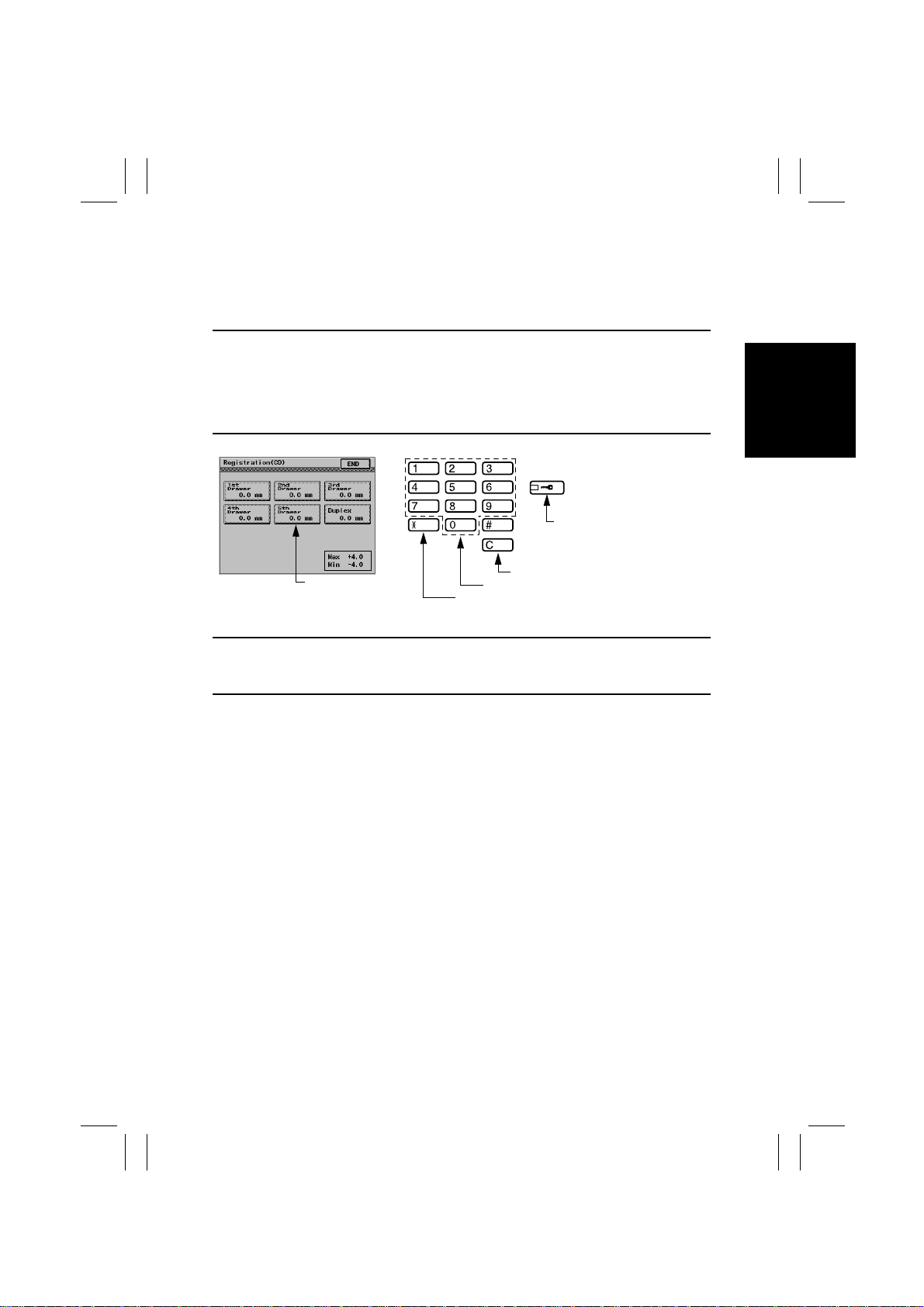
Adjust so that width A on the test pattern output falls
within the following range.
Registration (CD) -4.0 to +4.0
D-38
Page 42
FrameMaker Ver.5.5E(PC) Di350 DIS/REASSEMBLY, ADJUSTMENT
98.12.09
3. Call the Adjust mode to the screen.
4. Touch [Printer] and [Registration (CD)], in that order.
5. Select the paper source for which the adjustment is to be made.
6. Press the Clear key to clear the current setting.
7. Enter the new setting value from the 10-Key Pad.
Setting Instructions
If width A is wider than specifications, make the setting value smaller than the current one.
If width A is narrower than specifications, make the setting value greater than the current
one.
✽
If a single adjustment procedure does not successfully bring width A into the specified
range, try another setting value.
Use to change the + or - sign.
1171D032CA
Setting Value
Use to change the + or - sign.
Use to clear setting value.
Use to enter setting value.
1171D061CA
8. Touch the [END] key to validate the setting value.
Caution
Be sure to touch the END key before returning to normal operation mode. If the Panel
Reset Key is used, the previous setting remains valid.
9. Perform the same steps to adjust for the other paper sources.
D-39
Page 43
FrameMaker Ver.5.5E(PC) Di350 DIS/REASSEMBLY, ADJUSTMENT
98.12.09
(6) Registration (FD) (Printer)
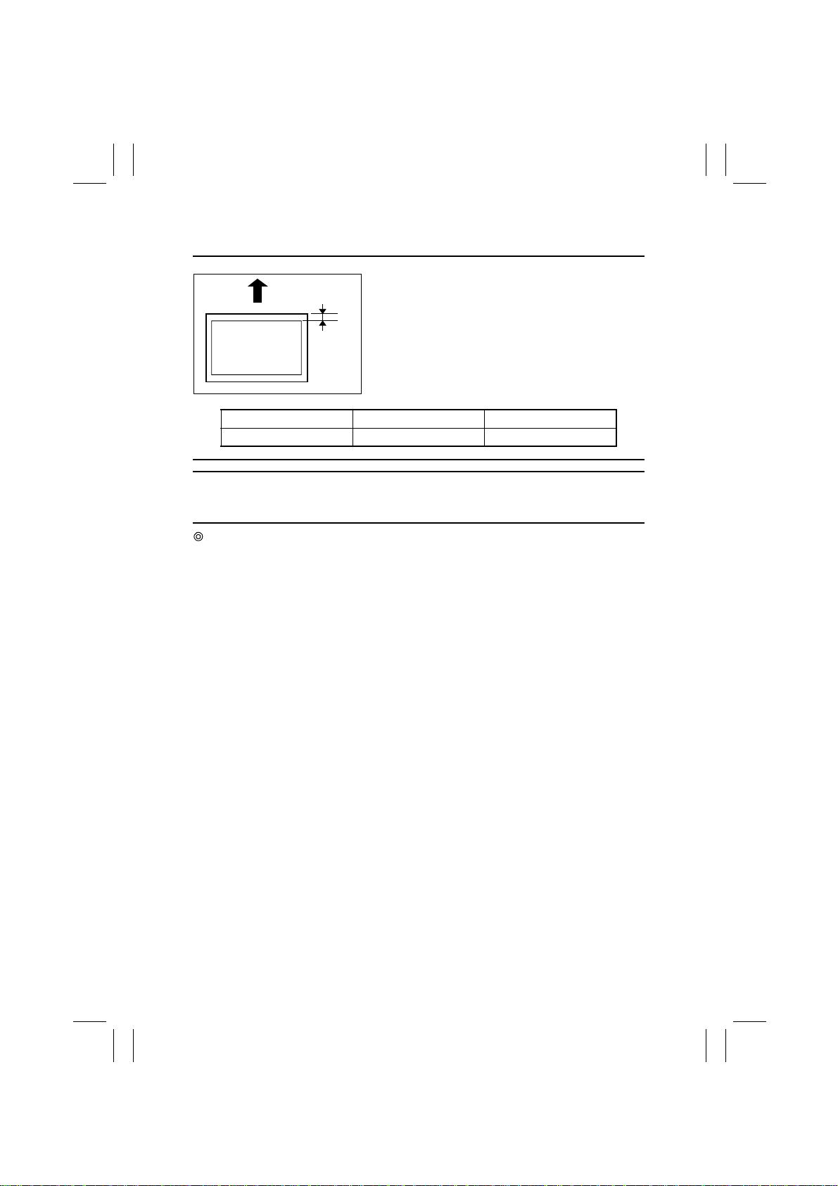
Requirement
Adjust so that width A on the test pattern output falls
within the following range.
A
1171D007AA
Specification Adjust Mode Setting Range
10 ±2.0 mm Registration (FD) -19 to +19
NOTE
This adjustment must be made when the PH Unit has been replaced and after Registration
(CD) (Printer) has been made.
Adjustment Procedure
1. Produce a test pattern. (For details, see 3-4. TEST PRINT.)
2. Check to see if width A on the test pattern meets the specifications.
If width A falls outside the specified range, perform these steps to make the adjustment.
D-40
Page 44
FrameMaker Ver.5.5E(PC) Di350 DIS/REASSEMBLY, ADJUSTMENT
98.12.09
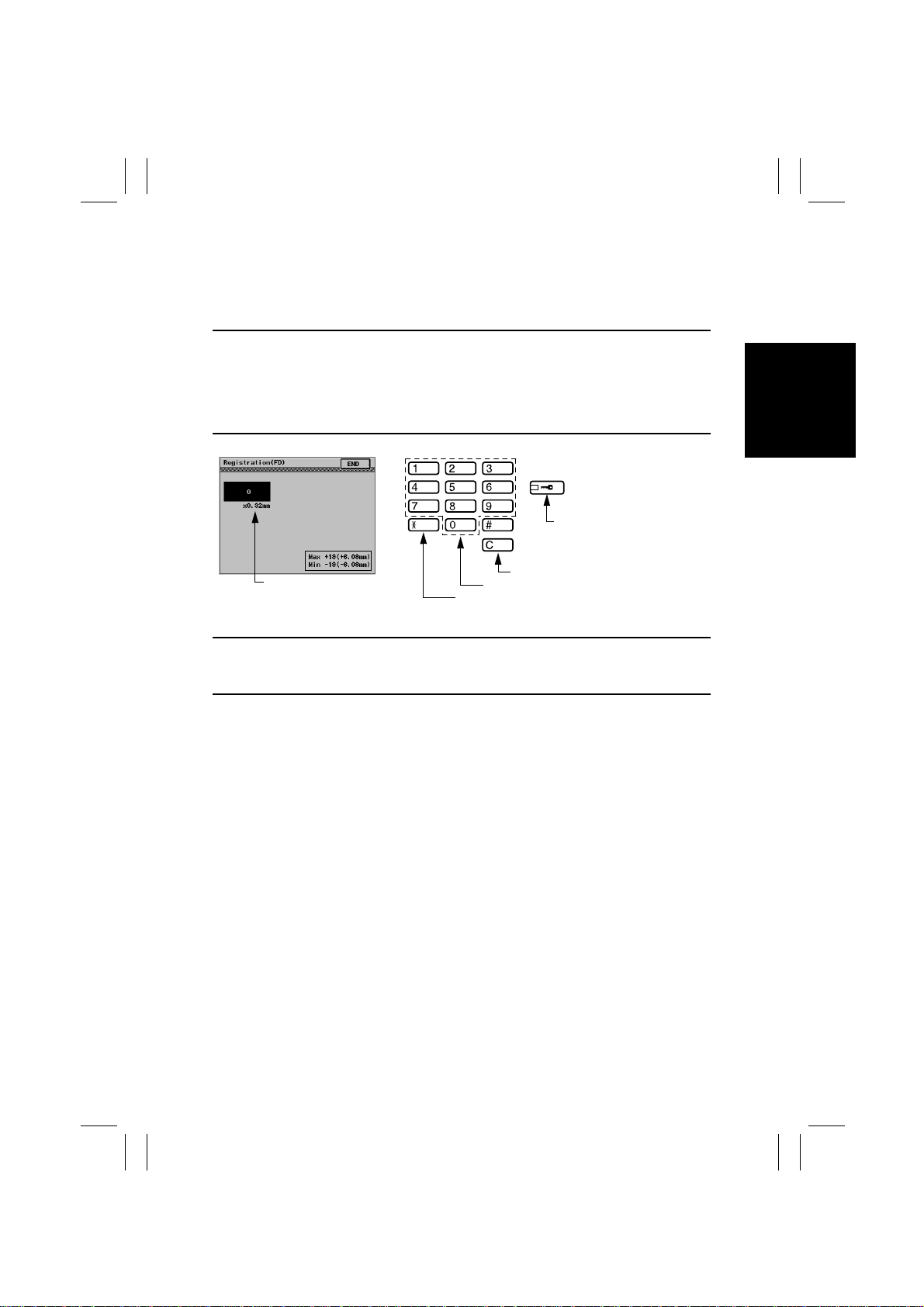
3. Call the Adjust mode to the screen.
4. Touch [Printer] and [Registration (FD)], in that order.
5. Select the paper source for which the adjustment is to be made.
6. Press the Clear key to clear the current setting.
7. Enter the new setting value from the 10-Key Pad.
Setting Instructions
If width A is wider than specifications, make the setting value smaller than the current one.
If width A is narrower than specifications, make the setting value greater than the current
one.
✽
If a single adjustment procedure does not successfully bring width A into the specified
range, try another setting value.
Use to change the + or - sign.
Setting Value
1171D033CA
Use to change the + or - sign.
Use to clear setting value.
Use to enter setting value.
1171D061CA
8. Touch the [END] key to validate the setting value.
Caution
Be sure to touch the END key before returning to normal operation mode. If the Panel
Reset Key is used, the previous setting remains valid.
D-41
Page 45
FrameMaker Ver.5.5E(PC) Di350 DIS/REASSEMBLY, ADJUSTMENT
98.12.09
(7) Registration (IR)
1. CD
Requirement
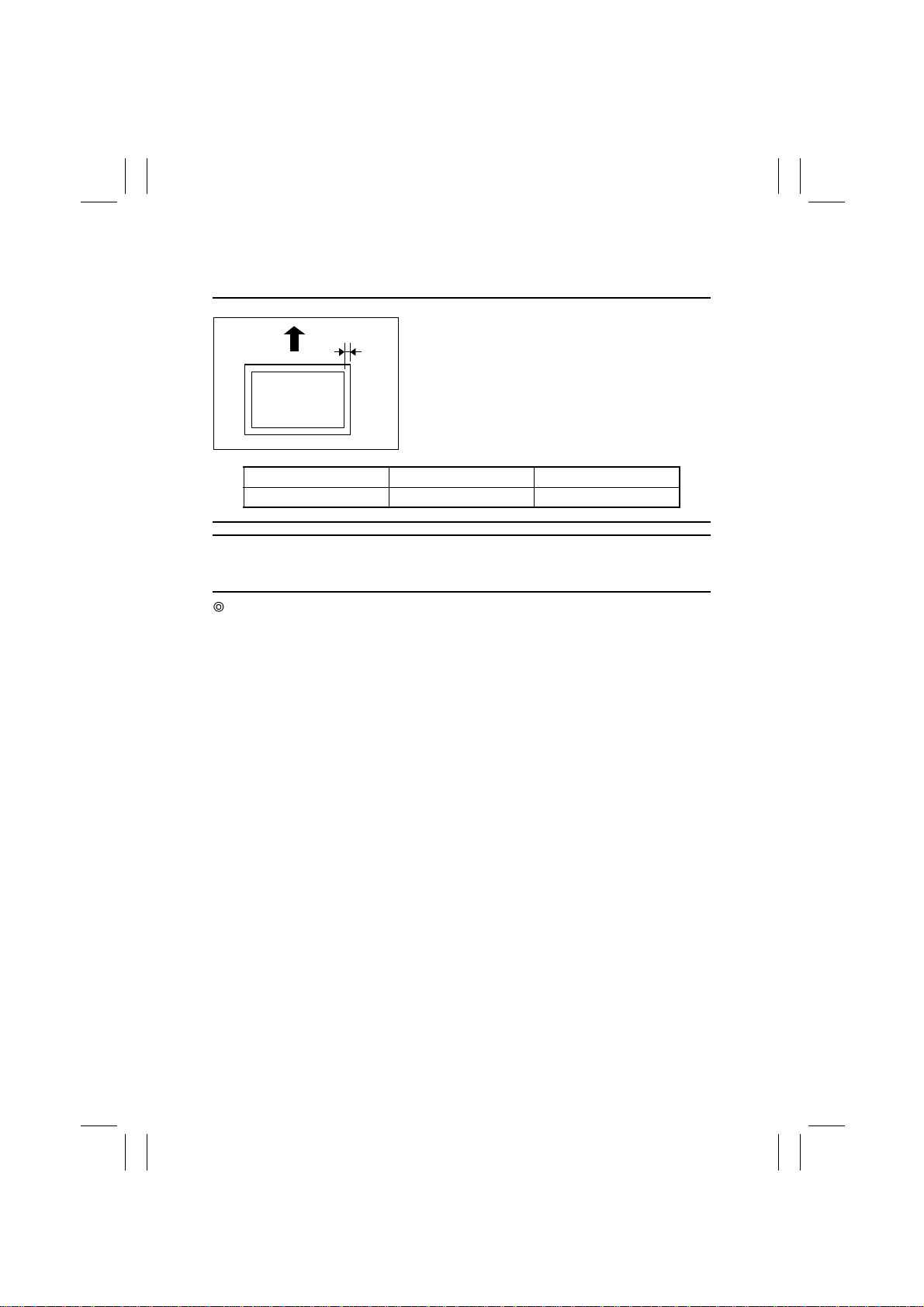
A
1171D009AA
Specification Adjust Mode Setting Range
10 ±2.0 mm Registration (CD) -127 to +127
NOTE
This adjustment must be made when the PH Unit has been replaced and after the adjustments of Registration (CD and FD) (Printer) and CD of Zoom Adjust (IR) have been made.
Adjustment Procedure
1. After the adjustments of Registration (CD and FD) (Printer) and CD of Zoom Adjust (IR)
have been completed, produce a test pattern. (For details, see 3-4. TEST PRINT.)
2. Place the test pattern output on the Original Glass and make a copy of it.
3. Check to see if width A on the test pattern copy meets the specifications.
If width A falls outside the specified range, perform these steps to make the adjustment.
Place the test pattern output after the adjustments of
Registration (CD and FD) (Printer) have been completed on the Original Glass and make a copy of it.
Adjust so that width A on the test pattern copy falls
within the following range.
D-42
Page 46
FrameMaker Ver.5.5E(PC) Di350 DIS/REASSEMBLY, ADJUSTMENT
98.12.09
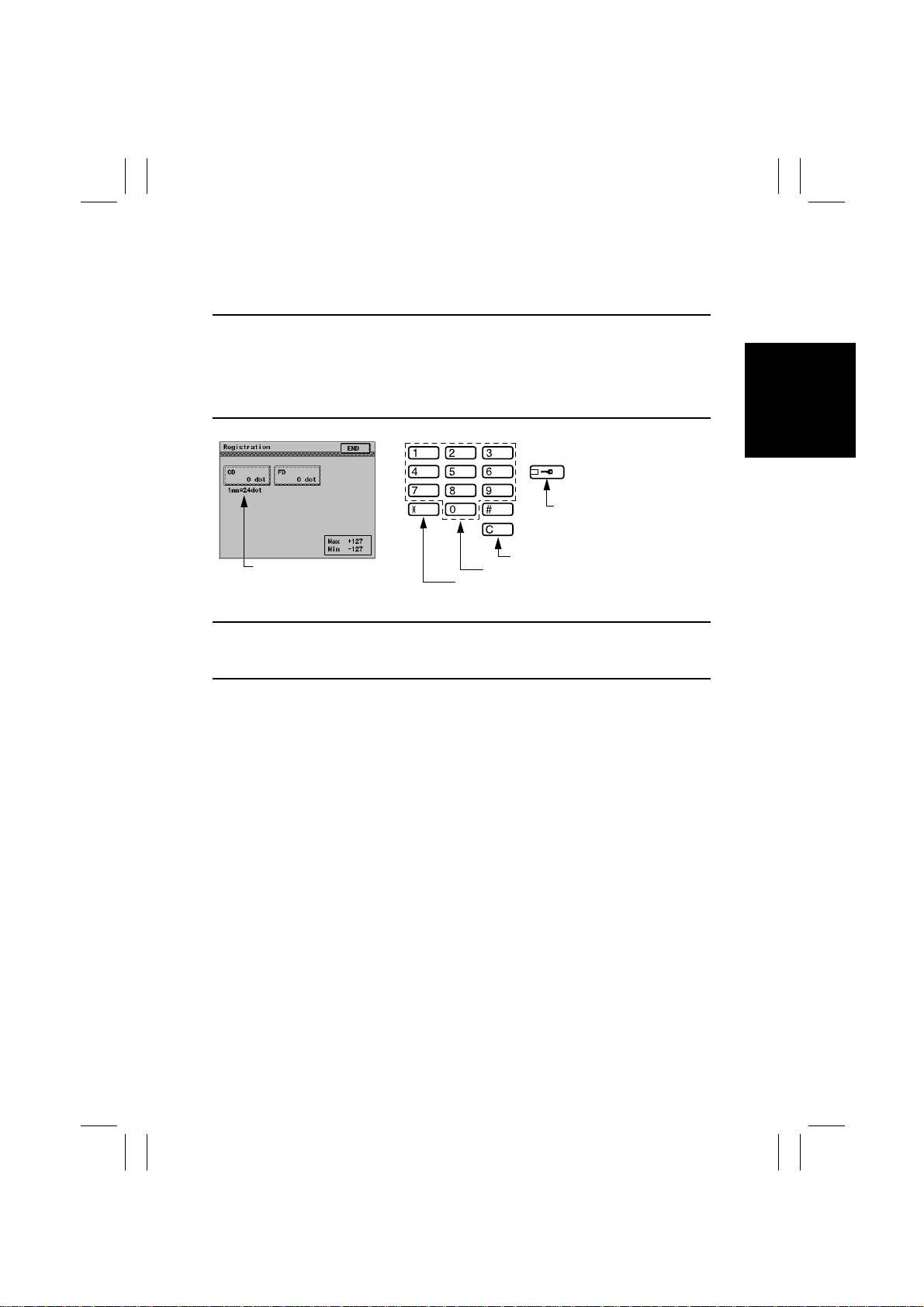
4. Call the Adjust mode to the screen.
5. Touch [IR], [Registration], and [CD], in that order.
6. Press the Clear key to clear the current setting.
7. Enter the new setting value from the 10-Key Pad.
Setting Instructions
If width A is wider than specifications, make the setting value smaller than the current one.
If width A is narrower than specifications, make the setting value greater than the current
one.
✽
If a single adjustment procedure does not successfully bring width A into the specified
range, try another setting value.
Use to change the + or - sign.
Setting Value
1171D034CA
Use to change the + or - sign.
Use to clear setting value.
Use to enter setting value.
1171D061CA
8. Touch the [END] key to validate the setting value.
Caution
Be sure to touch the END key before returning to normal operation mode. If the Panel
Reset Key is used, the previous setting remains valid.
D-43
Page 47
FrameMaker Ver.5.5E(PC) Di350 DIS/REASSEMBLY, ADJUSTMENT
98.12.09
2. FD
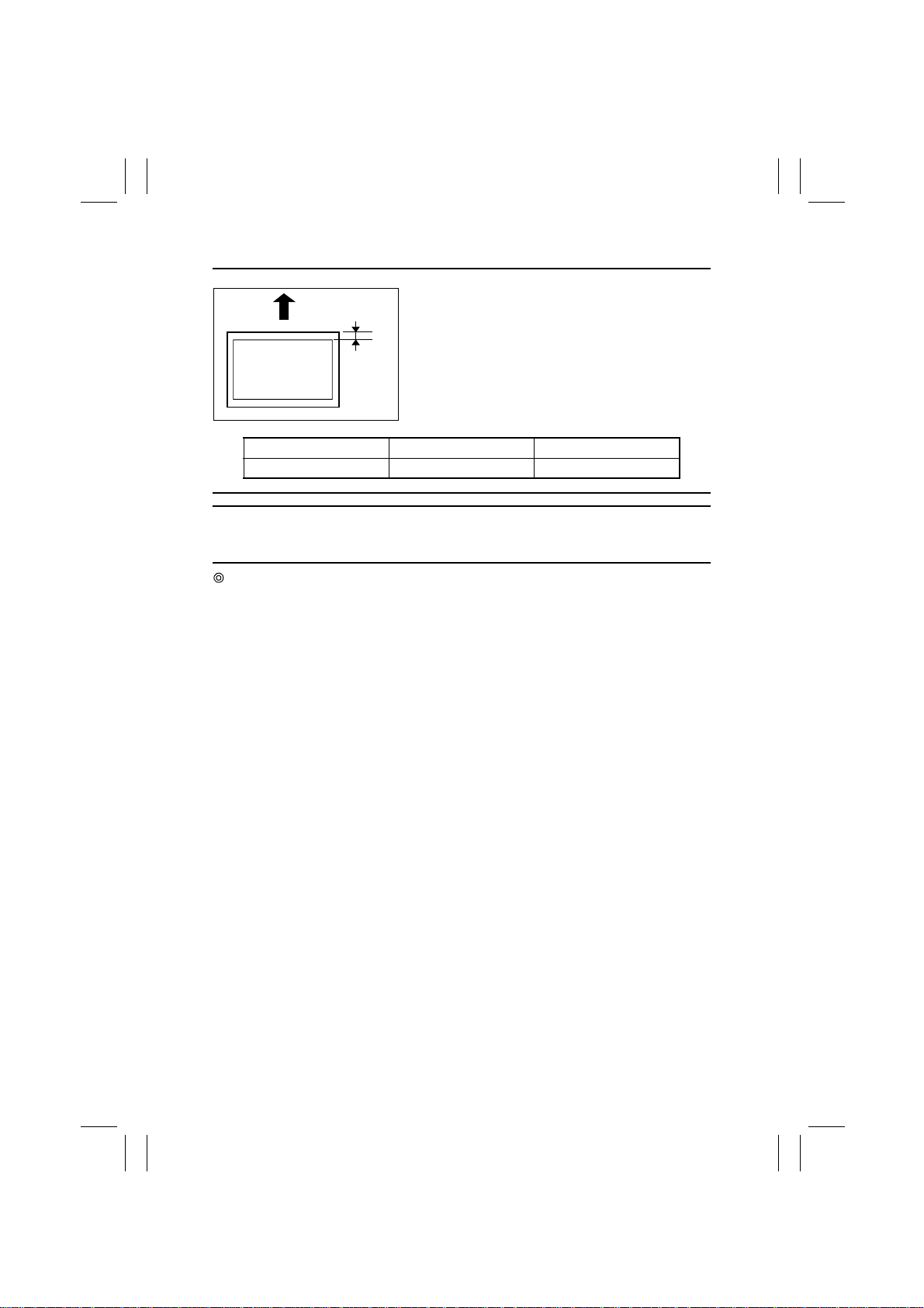
Requirement
1171D007AA
Specification Adjust Mode Setting Range
10 ±2.0 mm Registration (FD) -127 to +127
NOTE
This adjustment must be made when the PH Unit has been replaced and after the adjustments of Registration (CD and FD) (Printer) and FD of Zoom Adjust (IR) have been made.
Adjustment Procedure
1. After the adjustments of Registration (CD and FD) (Printer) and FD of Zoom Adjust (IR)
have been completed, produce a test pattern. (For details, see 3-4. TEST PRINT.)
2. Place the test pattern output on the Original Glass and make a copy of it.
3. Check to see if width A on the test pattern copy meets the specifications.
If width A falls outside the specified range, perform these steps to make the adjustment.
Place the test pattern output after the adjustments of
Registration (CD and FD) (Printer) have been completed on the Original Glass and make a copy of it.
A
Adjust so that width A on the test pattern copy falls
within the following range.
D-44
Page 48
FrameMaker Ver.5.5E(PC) Di350 DIS/REASSEMBLY, ADJUSTMENT
98.12.09
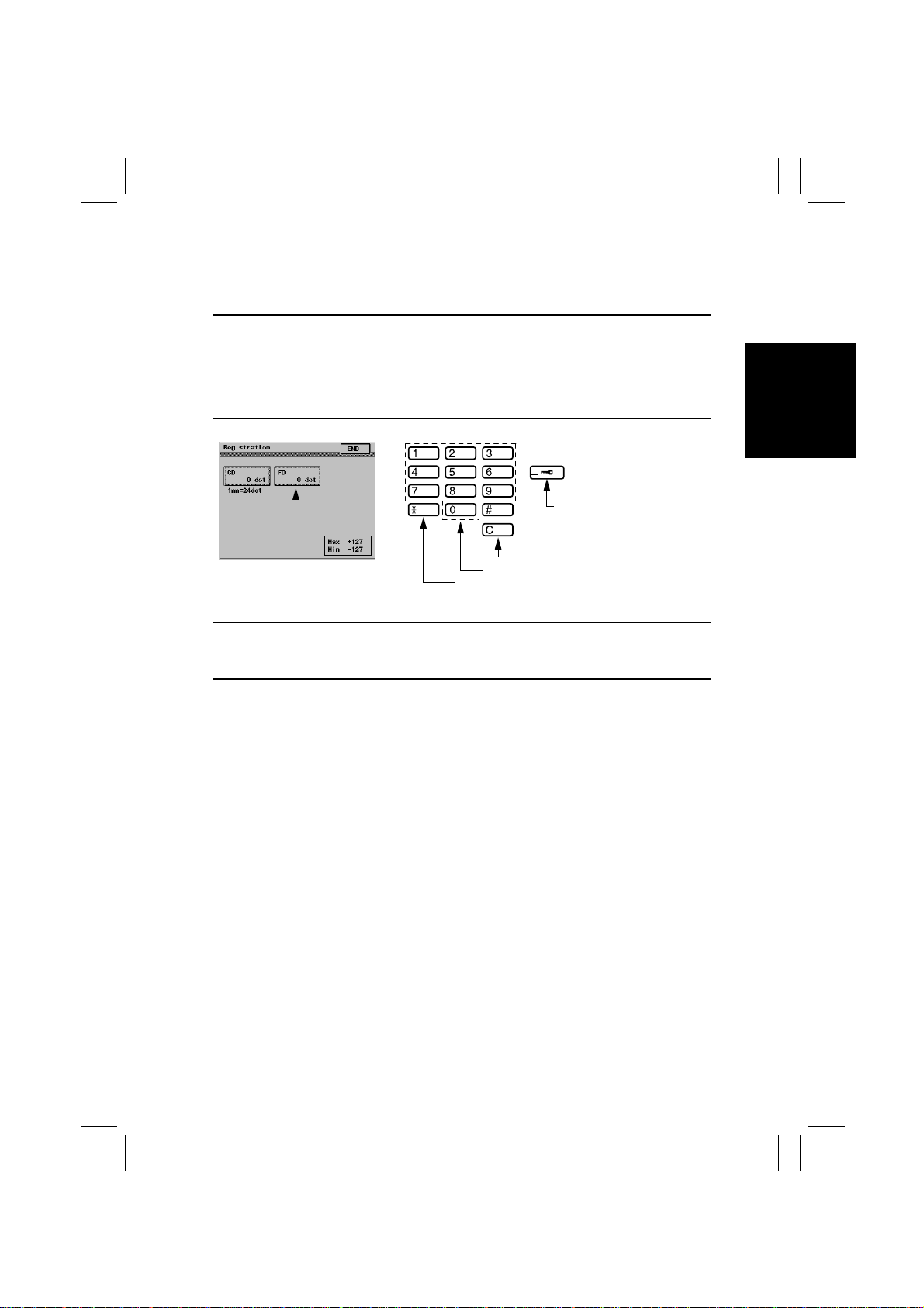
4. Call the Adjust mode to the screen.
5. Touch [IR], [Registration], and [FD], in that order.
6. Press the Clear key to clear the current setting.
7. Enter the new setting value from the 10-Key Pad.
Setting Instructions
If width A is wider than specifications, make the setting value smaller than the current one.
If width A is narrower than specifications, make the setting value greater than the current
one.
✽
If a single adjustment procedure does not successfully bring width A into the specified
range, try another setting value.
Use to change the + or - sign.
1171D034CA
Setting Value
Use to change the + or - sign.
Use to clear setting value.
Use to enter setting value.
1171D061CA
8. Touch the [END] key to validate the setting value.
Caution
Be sure to touch the END key before returning to normal operation mode. If the Panel
Reset Key is used, the previous setting remains valid.
D-45
Page 49
FrameMaker Ver.5.5E(PC) Di350 DIS/REASSEMBLY, ADJUSTMENT
98.12.09
(8) Zoom Adjust (IR)
1. CD
Requirement
1. The difference should be within ±1.0% of the actual length.
2. Adjust so that the following specifications are satisfied with a scale length of 300 mm.
Zoom Ratio Specification Adjust Mode Setting Range
Full size (×1.000) 300 ±3.0 mm Zoom Adjust (CD) 0.990 to 1.010
NOTE
This adjustment must be made when the Scanner Drive Cables have been replaced and
after the adjustments of Registration (CD and FD) (Printer) have been made.
Adjustment Procedure
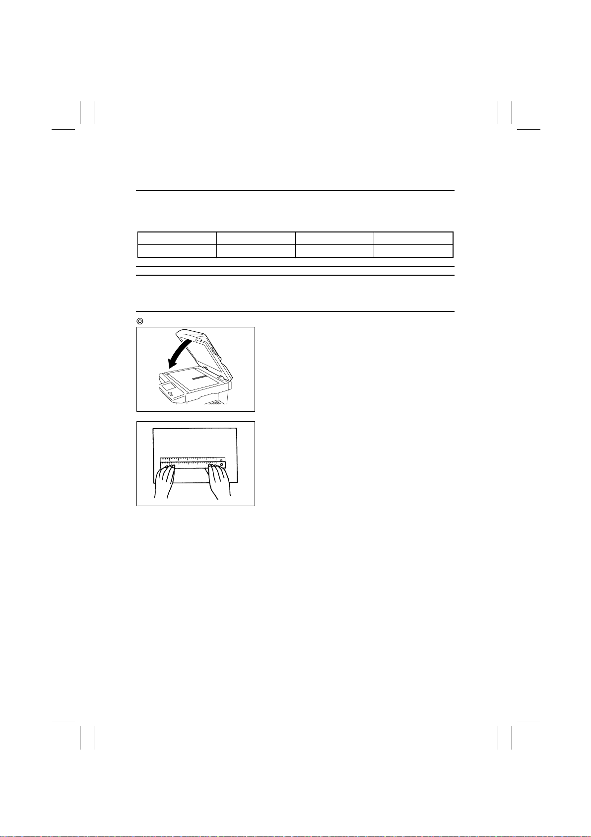
1167D111AA
1138D154AA
1. Place a scale in parallel with the Original Width
Scale and make a copy. (Note that the scale is perpendicular to the Original Length Scale.)
✽
Use the full size (×1.000) mode and A3 or 11” × 17”
paper.
✽
If the scale is of plastic and transparent, place a
blank sheet of paper over it.
2. Measure the length of the scale on the copy to find
the difference.
✽
If the difference is outside the specification, adjust
by following the procedure shown below.
D-46
Page 50
FrameMaker Ver.5.5E(PC) Di350 DIS/REASSEMBLY, ADJUSTMENT
98.12.09
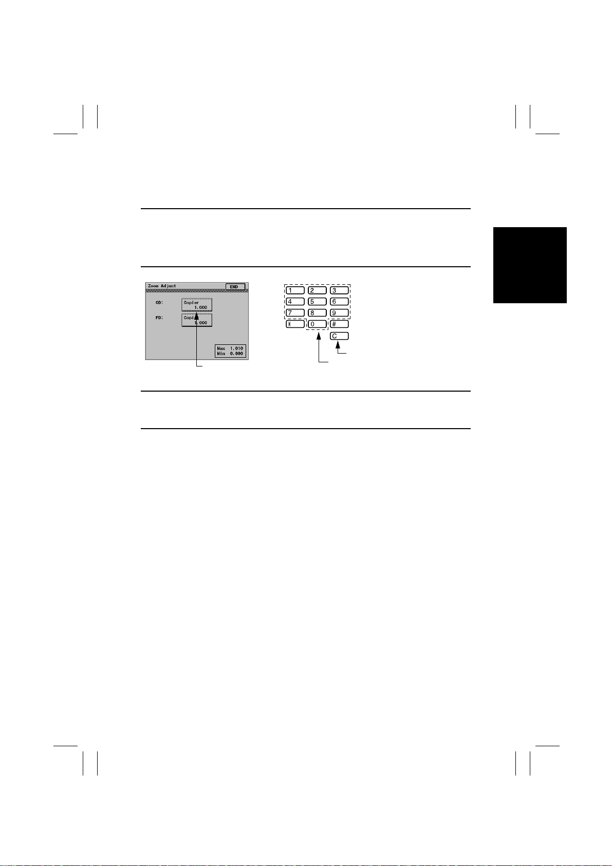
3. Call the Adjust mode to the screen.
4. Touch [IR], [Zoom Adjust], and [CD], in that order.
5. Press the Clear key to clear the current setting.
6. Enter the new setting value from the 10-Key Pad.
Setting Instructions
If the scale on the copy is longer than the actual scale, decrease the setting value.
If the scale on the copy is shorter than the actual scale, increase the setting value.
✽
If the measurement does not fall within the specifications through one setting, try another
setting.
Use to clear setting value.
1171D035CA
Setting Value
Use to enter setting value.
1167D069AA
7. Touch the [END] key to validate the setting value.
Caution
Be sure to touch the END key before returning to normal operation mode. If the Panel
Reset Key is used, the previous setting remains valid.
D-47
Page 51
FrameMaker Ver.5.5E(PC) Di350 DIS/REASSEMBLY, ADJUSTMENT
98.12.09
2. FD
Requirement
1. The difference should be within ±1.0% of the actual length.
2. Adjust so that the following specifications are satisfied with a scale length of 200 mm.
Zoom Ratio Specification Adjust Mode Setting Range
Full size (×1.000) 200 ±2.0 mm Zoom Adjust (FD) 0.990 to 1.010
NOTE
This adjustment must be made when the CCD Unit has been replaced and after the adjustments of Registration (CD and FD) (Printer) have been made.
Adjustment Procedure
1167D112AA
1134D124AA
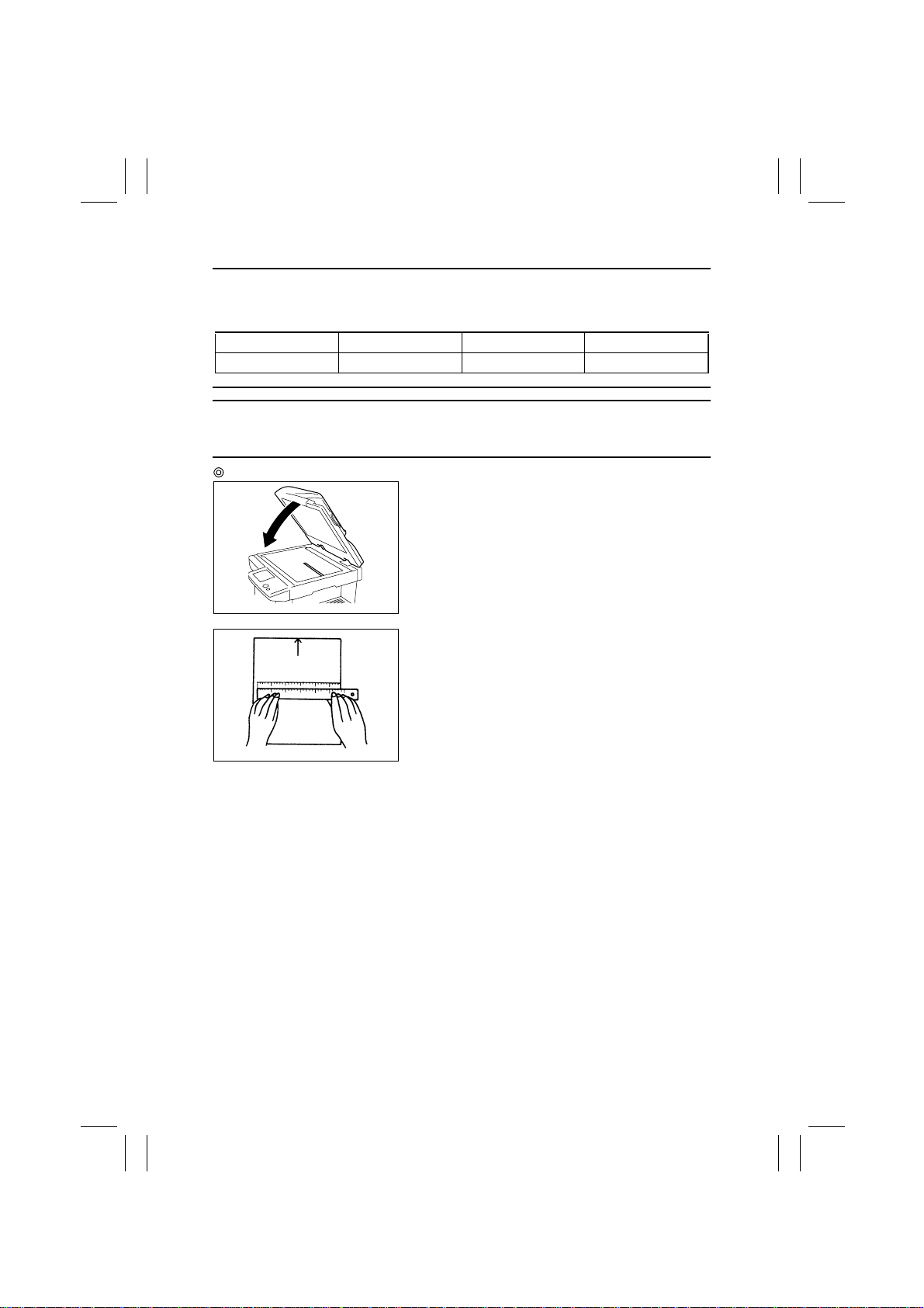
1. Place a scale in parallel with the Original Length
Scale and make a copy.
✽
Use the full size (X1.000) mode and paper with a
width of 200 mm or more.
✽
If the scale is of plastic and transparent, place a
blank sheet of paper over it.
2. Measure the length of the scale on the copy to find
the difference.
✽
If the difference is outside the specification, adjust
by following the procedure shown below.
D-48
Page 52
FrameMaker Ver.5.5E(PC) Di350 DIS/REASSEMBLY, ADJUSTMENT
98.12.09
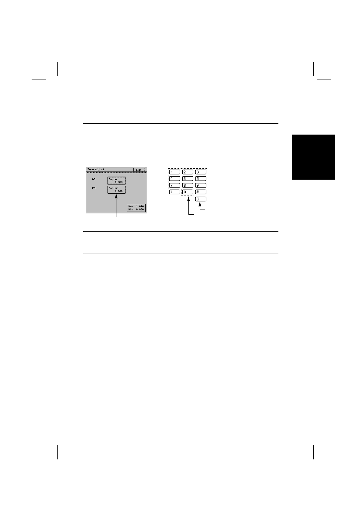
3. Call the Adjust mode to the screen.
4. Touch [IR], [Zoom Adjust], and [FD], in that order.
5. Press the Clear key to clear the current setting.
6. Enter the new setting value from the 10-Key Pad.
Setting Instructions
If the scale on the copy is longer than the actual scale, decrease the setting value.
If the scale on the copy is shorter than the actual scale, increase the setting value.
✽
If the measurement does not fall within the specifications through one setting, try another
setting.
Use to clear setting value.
1171D035CA
Setting Value
Use to enter setting value.
1167D069AA
7. Touch the [END] key to validate the setting value.
Caution
Be sure to touch the END key before returning to normal operating mode. If the Panel
Reset Key is used, the previous setting remains valid.
D-49
Page 53
FrameMaker Ver.5.5E(PC) Di350 DIS/REASSEMBLY, ADJUSTMENT
98.12.09
(9) IR-Erasure Width
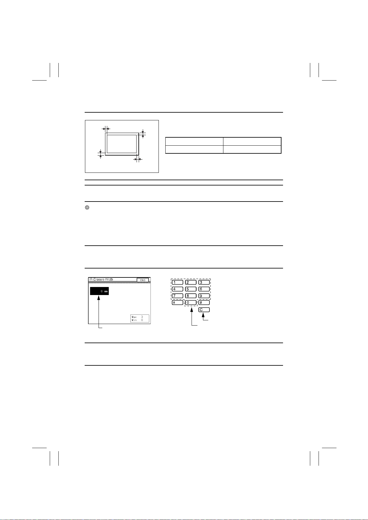
Requirement
A
Set so that the erase width along four edges of the
paper falls within the range of 0 to 3 mm.
A
Adjust Mode Setting Range
IR-Erasure Width 0 to 3
A
A
1171D062AA
NOTE
This adjustment must be made when a shadow is produced from the Original Scale.
Adjustment Procedure
1. Call the Tech. Rep. mode to the screen.
2. Touch [Tech. Rep. Choice].
3. Touch [IR-Erasure Width] to enter the IR-Erasure Width mode.
4. Press the Clear key to clear the current setting.
5. Enter the new setting value from the 10-Key Pad.
Setting Instructions
To make the erase width along four edges of the paper smaller, decrease the setting value.
To make the erase width along four edges of the paper greater, increase the setting value.
Use to clear setting value.
Setting Value
1171D064CA
Use to enter setting value.
1167D069AA
6. Touch the [END] key to validate the setting value.
Caution
Be sure to touch the END key before returning to normal operation mode. If the Panel
Reset Key is used, the previous setting remains valid.
D-50
Page 54
FrameMaker Ver.5.5E(PC) Di350 DIS/REASSEMBLY, ADJUSTMENT
98.12.09
3-6. OTHER ADJUSTMENTS
•
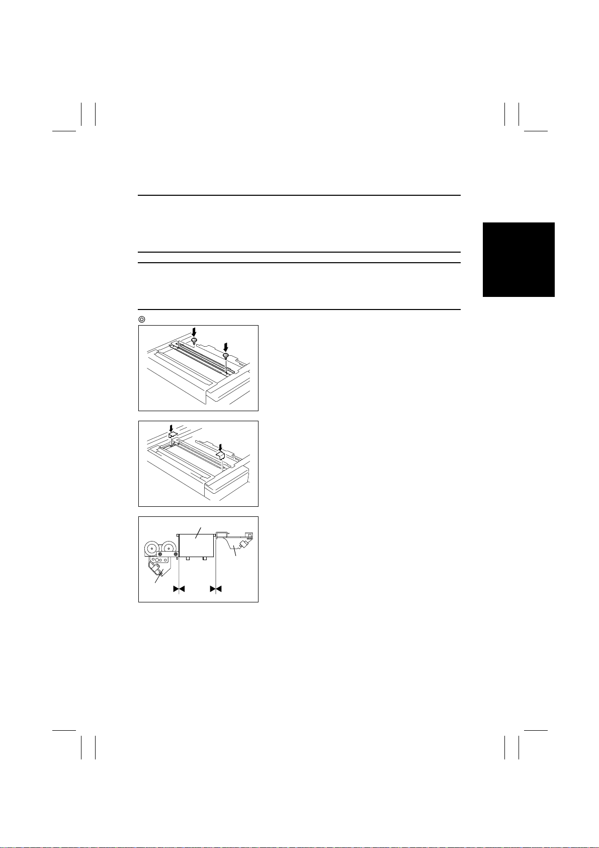
Focus-Positioning of the Scanner and 2nd/3rd Mirrors Carriage
NOTE
Make this adjustment after any of the following procedures has been performed:
•
After the Scanner Drive Cable has been replaced.
•
When the Scanner Fixing Bracket has been removed from the Scanner Drive Cable.
•
When the Scanner Drive Cable comes unwound.
Requirement
With the Scanner fixed to the Scanner Drive Cables, there should be no gap between the
Scanner/Mirrors Carriage Positioning Jig and the Scanner and also between the Scanner/
Mirrors Carriage Positioning Jig and the 2nd/3rd Mirrors Carriage.
Adjustment Procedure
1167D113AA
1167D114AA
Scanner/Mirrors Carriage Positioning Jig
2nd/3rd
Mirrors
Carriage
Scanner
1167D115AC
1. Remove the Exposure Lamp. (For details, see
steps 1 through 7, (8) Removal of the Scanner, 2-4
OPTICAL SECTION.)
2. Temporarily loosen the set screws of the cable
holding plate of the Scanner Drive Cable.
3. Fit the Scanner/Mirrors Carriage Positioning Jigs in
the space between the Scanner and 2nd/3rd Mirrors Carriage.
4. Press the Scanner up against the jig and 2nd/3rd
Mirrors Carriage and, at the same time, tighten the
set screws of the cable holding plate.
D-51
Page 55
FrameMaker Ver.5.5E(PC) Di350 DIS/REASSEMBLY, ADJUSTMENT
98.12.09
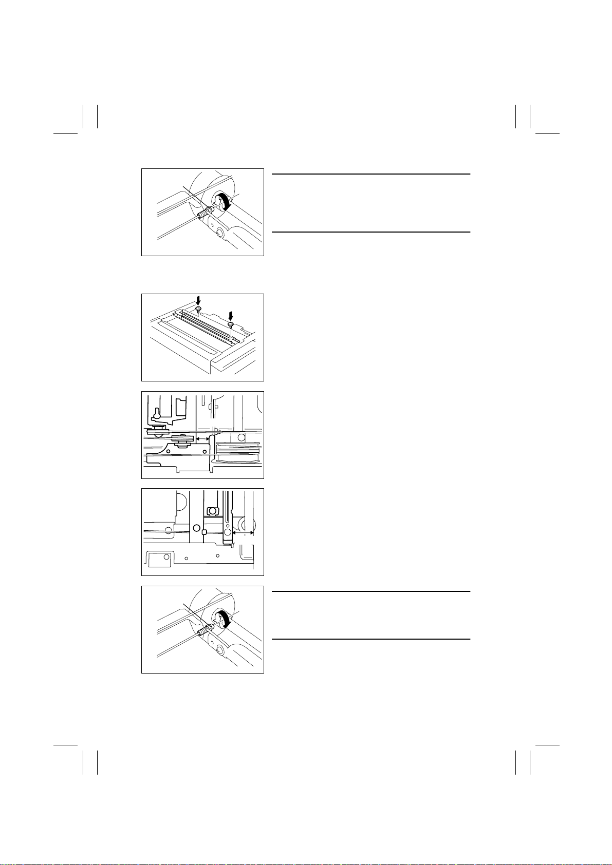
Adjusting Screw
NOTE
If the Scanner does not run parallel with the 2nd/3rd
Mirrors Carriage when the Scanner/Mirrors Carriage
Positioning Jigs are in position, turn the adjusting
screw for the rear Scanner Drive Cable as necessary.
1167D116AB
✽
If the Scanner/Mirrors Carriage Positioning Jigs are not available, follow these steps to
make the adjustment.
1. Temporarily loosen the set screws of the cable
holding plate of the Scanner Drive Cable.
1167D113AA
2. Obtain a distance of 13 mm between the 2nd/3rd
Mirrors Carriage and rail.
13 mm
1167D117AC
Adjusting Screw
3. Secure the Scanner where it is located at a position 21 mm from the right side face.
4. Tighten the set screws of the cable holding plate.
21 mm
1167D118AC
NOTE
If the Scanner does not run parallel with the 2nd/3rd
Mirrors Carriage, turn the adjusting screw for the rear
Scanner Drive Cable as necessary.
1167D116AB
D-52
Page 56
FrameMaker Ver.5.5E(PC) Di350 DIS/REASSEMBLY, ADJUSTMENT
98.12.09
4 MISCELLANEOUS
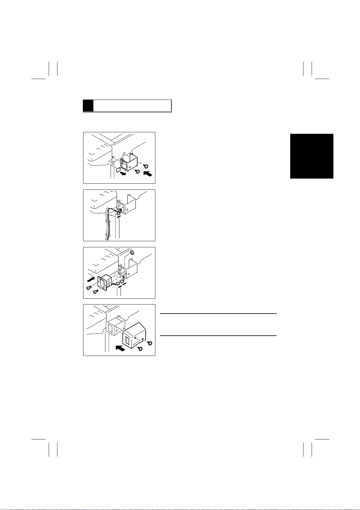
4-1. INSTALLATION OF THE KEY COUNTER SOCKET (OPTION)
1. Remove the Front Cover.
2. Remove the knockout from the Front Upper Cover.
3. Using two screws, secure the Counter Mounting
Bracket.
1167D022AB
4. Route the harness of the Key Counter as shown.
1167D025AB
1167D023AB
1167D024AB
5. Connect the Key Counter Socket connector.
6. Using one screw and one screw and nut, secure
the counter socket.
7. Using two screws, secure the Key Counter Cover.
NOTE
When the Key Counter Socket is mounted, set to “ON
the “Key Counter” available from the Security mode.
”
D-53
Page 57
FrameMaker Ver.5.5E(PC) Di350 DIS/REASSEMBLY, ADJUSTMENT
98.12.09
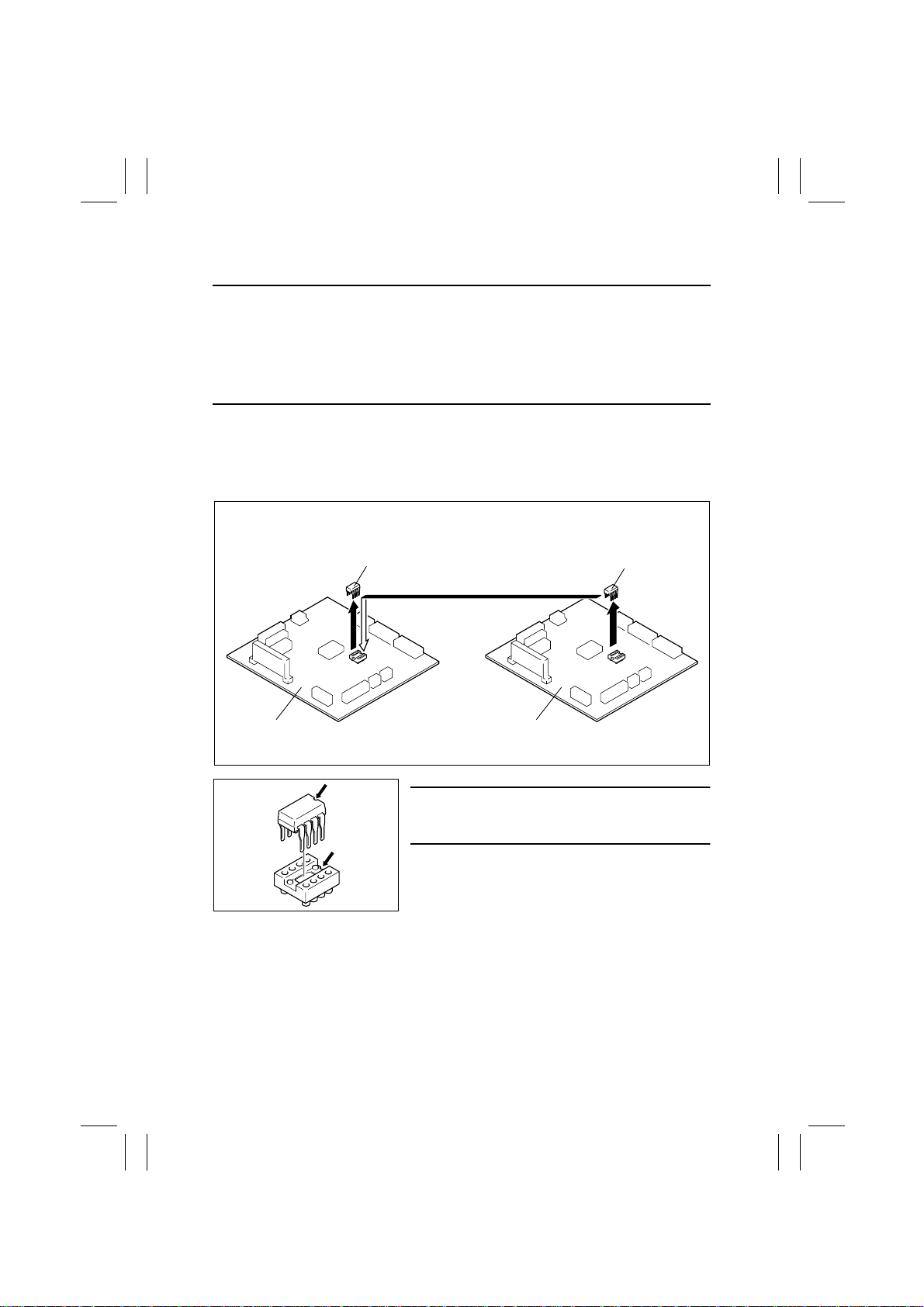
4-2. REMOUNTING THE EEPROM (IC3A)
NOTES
•
If the Imaging Cartridge is not to be replaced after the Master Board has been replaced
with a new one, be sure to remount the EEPROM (IC3A) from the old to new Master
Board.
•
If the Master Board has been replaced with a new one and the EEPROM (IC3A) has not
been remounted, be sure to replace the Imaging Cartridge with a new one. Because the
EEPROM contains no data in this case, make settings and readjustments as necessary.
1. Remove the Master Board. (For details, see 2-2. REMOVAL OF CIRCUIT BOARDS
AND OTHER ELECTRICAL COMPONENTS.)
2. Demount the EEPROM (IC3A) from the new Master Board.
3. Demount the EEPROM (IC3A) from the old Master Board and remount it onto the new
Master Board.
New Master Board
New EEPROM
A
A
1171D049AA
Old EEPROM
Old Master Board
1171D048AA
NOTE
Note the alignment notch on the EEPROM (IC3A)
when mounting the IC.
D-54
 Loading...