

Page 1

HARDWARE MANUAL
9222-2887-11 P-A208
E
Page 2
BEFORE YOU BEGIN
2
This manual may not be copied in part or whole without prior
written permission from Minolta. Every necessary precaution
has been taken to ensure the accuracy of this instruction manual. Minolta is not responsible for any loss or damage caused
from the operation of this product.
Thank you for purchasing this Minolta product.Please take the time to read through this instruction manual so you can enjoy all the features of your new scanner.
This manual contains information regarding products introduced before September, 2002. To
obtain compatibility information for products released after this date, contact a Minolta Service
Facility (www.minoltasupport.com). This product is designed to work with accessories manufactured and distributed by Minolta. Using accessories or equipment not endorsed by Minolta may
result in unsatisfactory performance or damage to the product and its accessories.
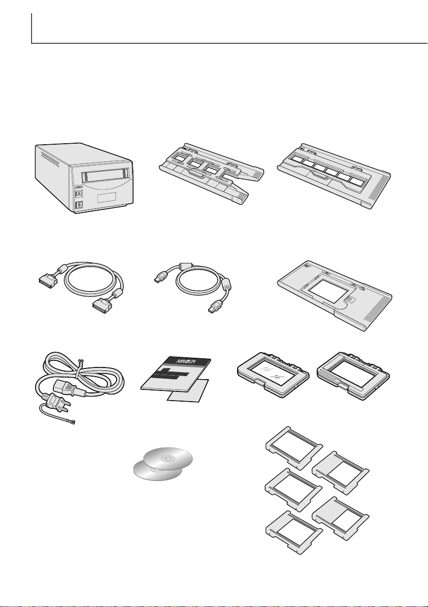
Check the packing list before using this product.If any items are missing, immediately contact
your dealer.
AC power cord
(Shape of plug varies
with destination)
Scanner unit
Slide Mount Holder
SH-P1
35mm Film Holder
FH-P1
Universal Holder
UH-P1
Standard Attachment HA-P1
Glassless Attachment HA-P2
Film Mask Set FM-P1
SCSI cable SC-P1 IEEE 1394 cable FC-P1
DiMAGE Scan Utility CD-ROM,
DiMAGE Instruction Manuals-CD-ROM
Quick Reference Guide
and Minolta International
Warranty Certificate
Page 3

3
FOR PROPER AND SAFE USE
Read and understand all warnings and cautions before using this product.
WARNING
• Use only within the voltage range specified on the unit. Inappropriate current may cause
damage or injury through fire or electric shock.
• Do not disassemble this product. Electric shock may cause injury if a high-voltage circuit inside
the product is touched. Take the product to a Minolta Service Facility when repairs are required.
• Immediately unplug the unit and discontinue use if the product is dropped or subjected to an
impact in which the interior is exposed. The continued use of a damaged product may cause
injuries or fire.
• Store this product out of reach of children. Be careful when around children not to harm them
with the product or parts.
• Do not operate this product or handle the power cord with wet hands. Do not place a container
with liquid near the product. If liquid comes in contact with the product, immediately unplug the
unit. The continued use of a product exposed to a liquid may cause damage or injury through
fire or electric shock.
• Do not insert hands, inflammable objects, or metal objects such as paper clips or staples into
this product. It may cause damage or injury through fire or electric shock. Discontinue use if an
object enters the product.
• Do not use the product near inflammable gases or liquids such as gasoline, benzine, or paint
thinner. Do not use inflammable products such as alcohol, benzine, or paint thinner to clean the
product. The use of inflammable cleaners and solvents may cause an explosion or fire.
• When unplugging the unit, do not pull on the power cord. Hold the plug when removing the cord
from an outlet.
• Do not damage, twist, modify, heat, or place heavy objects on the power cord. A damaged cord
may cause damage or injury through fire or electric shock.
• If the product emits a strange odor, heat, or smoke, discontinue use. Immediately unplug the
product. The continued use of a damaged product or part may cause injuries or fire.
•Take the product to a Minolta Service Facility when repairs are required.
• This product should only be operated in the upright position. Inappropriate placement may result
in fire.
• Damage or injury through fire or electric shock may result if the product is used or stored in the
following conditions:
In humid or dusty environments
In direct sunlight or hot environments
In smoky or oily areas
In unventilated areas
On unstable or unlevel surfaces
• Insert the plug securely into the electrical outlet.
• Do not use if the cord is damaged.
• Do not connect the ground to a gas pipe, telephone ground, or water pipe. Improper grounding
can result in injury from electric shock.
• Unplug the product when cleaning or when the unit is not in use for long periods.
•Periodically check that the power cord is not damaged and the plug is clean. Dust and dirt that
may collect between the prongs of the plugs may result in fire.
CAUTION
Page 4

TABLE OF CONTENTS
4
System requirements......................................................................................................5
Names of parts ..............................................................................................................6
Scanner setup ................................................................................................................7
Removing the optics locking screw ....................................................................7
Tr ansporting the scanner ........................................................................7
Before connecting the scanner to the computer ................................................7
Connecting the SCSI cable ................................................................................8
Connecting the IEEE 1394 (FireWire) cable ......................................................9
Auto Power Save ................................................................................................9
Loading the film holders ..............................................................................................10
Handling film......................................................................................................10
Where is the emulsion? ....................................................................................10
Loading 35mm film strips ..................................................................................10
Loading 35mm mounted slides ........................................................................10
Inserting attachments into the Universal holder................................................11
Using the standard attachment ........................................................................12
Using the glassless attachment ........................................................................12
Multi-format Set HS-P1 (sold separately)..........................................................13
Loading a film holder into the scanner..............................................................15
Ejecting a film holder ........................................................................................15
Scanner notes ..............................................................................................................16
Easy Scan Utility ..............................................................................................16
About the DiMAGE Scan Utility ........................................................................16
Film format and type settings............................................................................16
Disconnecting the scanner................................................................................16
SCSI cable ............................................................................................16
IEEE 1394 (FireWire) cable ..................................................................16
Digital ICE
3
system requirements......................................................................18
Scanner resolution ............................................................................................19
Scanner color profiles ......................................................................................19
Job file lists ..............................................................................................................20
35mm ..............................................................................................................20
6 X 4.5 ..............................................................................................................21
6 X 6 ..............................................................................................................22
6 X 7 ..............................................................................................................23
6 X 8 ..............................................................................................................24
6 X 9 and Multi-format 6 X 9 ............................................................................25
Multi-format 35mm ............................................................................................25
Troubleshooting ............................................................................................................26
Checking software installation - Windows ........................................................27
Technical support ..............................................................................................28
Warranty and product registration ....................................................................28
Image data sheet..........................................................................................................29
Technical specifications ................................................................................................30
This manual contains information specific to this model scanner. This includes hardware setup
and use as well as notes about software operation for this model scanner. See the supplied
DiMAGE Scan Utility software manual for information on the installation and operation of the scanner software.
Page 5

5
SYSTEM REQUIREMENTS
SCSI: Pentium 166MHz or later processor.
IEEE 1394: Pentium II or later processor.
A Pentium III processor is recommended when
scanning with 16-bit color depth. For Digital ICE
3
requirements, see page18.
A minimum of 96 MB of RAM (Windows (128MB with Windows XP)) or 64 MB of RAM (Macintosh) in addition to the requirements for the operating system and applications is required. 256 MB or more is necessary
when scanning with 16-bit color depth; 512 MB or more is recommended.
For Digital ICE
3
requirements, see page18.
A High Color (16bit) 640 x 480 pixel monitor is
required.
1024 x 768 pixels is recommended.
TWAIN driver compatible with Photoshop 4.0.1,
5.0.2, 5.5, 6.0, and 7.0, and PhotoshopLE 5.0.
Recommended SCSI boards: Adaptec SCSI Card
19160, Adaptec SCSI Card 29160, Adaptec SCSI
Card 29160N.
Recommended IEEE boards: Adaptec Fireconnect
4300, PROCOMP SpeedDemon 400P. Standard
OHCI compatible non-DV-dedicated IEEE 1394
ports guarantied by the computer manufacturer can
be used.
PC / AT compatible computers
Operation is not guarantied for custom or home-built machines.
The scanner cannot be used with notebook computers.
SCSI: preinstalled Windows 98, 98 Second Edition,
Me, 2000 Professional, NT 4.0, XP.
IEEE 1394: preinstalled Windows Me, 2000
Professional, XP.
Mac OS 8.6* to 9.2.2, and
OS 10.1.3 to 10.1.5.
A 640 x 480 pixel monitor capable of displaying
32,000 colors is required.
1024 x 768 pixels is recommended.
SCSI: PowerPC 604 or later
FireWire: PowerPC G3 or later.
PowerPC G4 processor is recommended when
scanning with 16-bit color depth. For Digital ICE
3
requirements, see page18.
Plug-in compatible with Photoshop 5.0.2, 5.5, 6.0,
and 7.0, and PhotoshopLE 5.0.
2 GB or more of available hard disk space is required. 6 GB or more of available hard disk space is necessary when scanning with 16-bit color depth; 8 GB or more is recommended.
For Digital ICE
3
requirements, see page18.
Macintosh
Recommended SCSI boards: Adaptec
PowerDomain 29160N, PowerDomain 2930U,
PowerDomain 2940UW, or PowerDomain
2940U2W.**
Only the standard built-in IEEE interface supplied
by Apple Computer, Inc.
* To use preinstalled Mac OS 8.6 with a built-in FireWire port, a Firewire 2.2 to 2.3.3 extension
must be installed. This software can be downloaded free of charge from the apple web site at
http://www.apple.com.
**Boards must be guarantied by the manufacturer to work with the computer and operating sys-
tem.
The computer and the operating system must be guarantied by the manufacturer to support IEEE
1394 (FireWire), or SCSI interface.
Check the Minolta web site for the latest compatibility information:
Europe: http://www.minoltasupport.com
North America: http://www.minoltausa.com.
Page 6
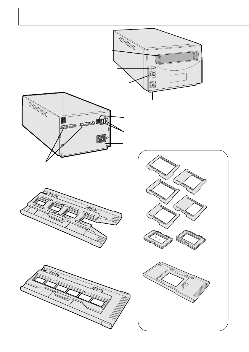
NAMES OF PARTS
6
Slide Mount Holder (p. 10)
35mm Film Holder (p. 10)
Universal Holder (p. 11)
Film attachments
Film masks
Front door
Indicator lamp
Power switch
Eject button
SCSI ID switch
IEEE 1394 (FireWire) ports
Dip switch
AC terminal
SCSI ports
Page 7
7
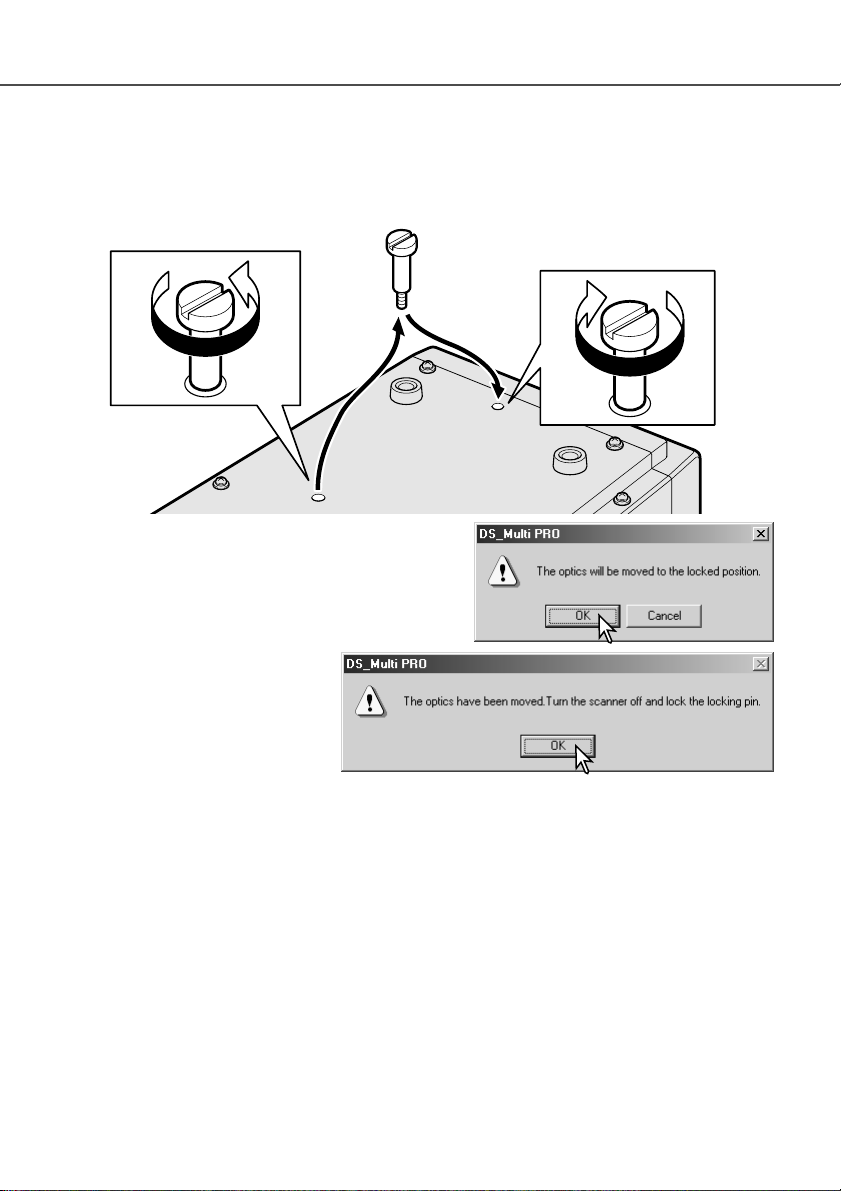
SCANNER SETUP
Transporting the scanner
To prevent damage when transporting the scanner, the
optics locking screw must be used.Before inserting the
screw in the lock position, the scanner must be initialized with the DiMAGE Scan Utility.
With the scanner connected to the
computer and the DiMAGE Scan
Utility running, press the control
(Windows) or command (Macintosh)
key plus the shift and L keys simultaneously. A window indicating the
command will be displayed;click the
OK button to move the optics to the lock position.
A message stating the completion of the operation will be displayed;click the OK button. Turn off
the computer and scanner.Disconnect the cable and power cord from the scanner and screw the
optic locking screw in the lock position.
Removing the optics locking screw
Before the scanner can be used, the optics locking screw on the bottom panel of the scanner
must be removed with a flat-head screwdriver. The locking screw is necessary to transport the
scanner.Place the screw in the storage position toward the front of the scanner body for future
use.
Before connecting the scanner to a computer
Before connecting the scanner to a computer, the the DiMAGE Scan Utility must first be installed.
Read the software instruction manual for the installation procedure.
The scanner should be placed on a level surface free from vibrations. It should be located away
from direct sunlight and in a clean, dry, well-ventilated area.
Page 8
SCANNER SETUP
8
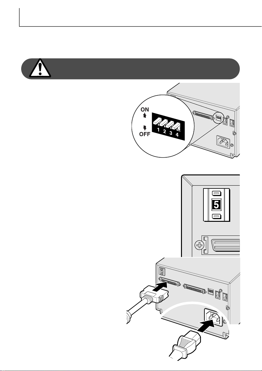
Connecting the SCSI cable
The scanner is supplied with an ultra SCSI D-sub half-pitch 50-pin cable. Contact your dealer if a
different cable is required.
The computer and all peripheral devices must be off
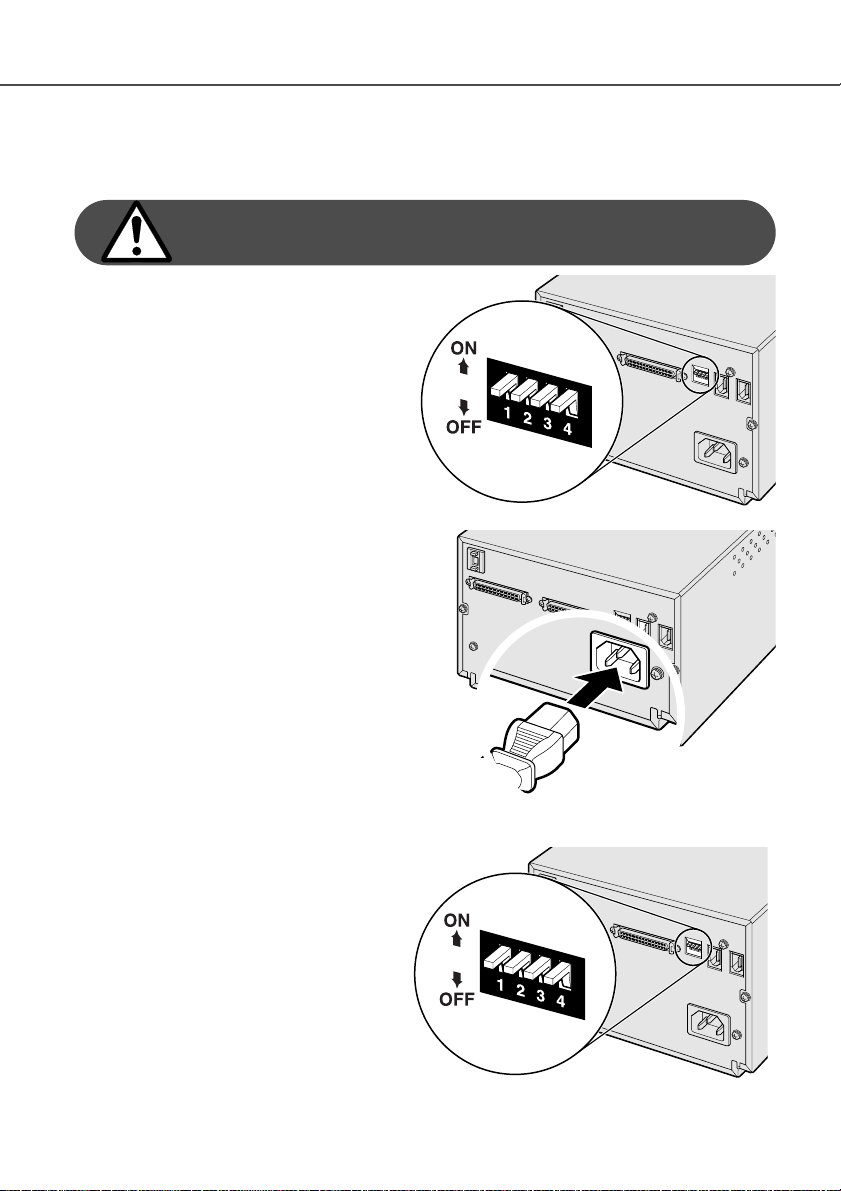
before connecting the scanner.
The terminator dip switch on the back of the
scanner eliminates the need for an external terminator. If the scanner is to be the only SCSI
device connected to the computer or it is the last
device in a daisy chain, switch number 1 should
be in the on position; terminating the SCSI chain
helps to suppress noise, not terminating a chain
can cause slowdowns, data errors, and crashes.
If the scanner is to be connected somewhere
within a daisy chain, switch 1 should be in the
off position. The initial setting for all the switches
is on. Dip switch 4 must be in the on position to
use a SCSI interface.
Connect the scanner to the computer or SCSI
chain with the cable. Either SCSI port can be
used for the connection.
Plug the power cord into the back of the unit.
The other end of the power cord should be
plugged into a grounded outlet.
Set the SCSI ID for the scanner by pressing the buttons above and
below the ID number window. Devices in the same chain must have
unique ID numbers. Depending on the computer system, some SCSI
IDs may already be assigned:
IBM PC/AT 7 - SCSI host adapter
Macintosh 0 - internal hard drive
3 - internal CD-ROM drive
7 - operating system
IDE Macintosh systems do not use SCSI ID 0 for the hard drive. SCSI
ID 3 is available on the external bus on Macintosh systems with a
dual bus.
Page 9
9
Connecting the IEEE1394 (FireWire) cable
The scanner is supplied with an IEEE 1394 (FireWire) cable. Up to 63 devices can be attached to
a computer using this interface. However, the number of devices is limited to 16 when using a
daisy-chain configuration.
The computer and all peripheral devices must be off
before connecting the scanner.
Set dip switch number 4 to the off position to
active the IEEE ports. Switch 4 must be
moved to the on position if a SCSI cable is
used.
Connect the scanner to the computer or
IEEE peripheral chain with the cable. Either
IEEE port can be used for the connection.
Plug the power cord into the back of the unit.
The other end of the power cord should be
plugged into a grounded outlet.
Auto Power Save
The scanner automatically turns the scanning light source off during long periods of
inactivity to save energy and preserve the life
of the fluorescent tube. Though not recommended, the auto-power-save function can
be disabled by setting dip switch number 2 to
the off position.
Page 10
LOADING THE FILM HOLDERS
10
Loading 35mm mounted slides
The Slide Mount Holder SH-P1 is for mounted 35mm film.
Up to four slide can be placed in the holder. Slide mounts
must be between 1mm and 2mm thick to fit the holder.
Glass mounts cannot be used; the glass refracts the light
resulting in distorted and unevenly illuminated scans.
With the cover hinges away from you, open the holder by
lifting on the latch on the cover.
Handling film
To achieve the best possible reproduction from the scanner, the film and film holder should be
free from dust and dirt. Always work with processed film in a clean, dust-free environment. Handle
film by the edges or mount to prevent fingerprints and dirt marring the image area. Special lint
free gloves are available from photographic equipment retailers for film handling as well as antistatic cloths, brushes, and blowers for removing dust. Film cleaner can be used to remove oil,
grease, or dirt from film; carefully follow the manufacturer's instructions and precautions for the
film cleaning solvent.
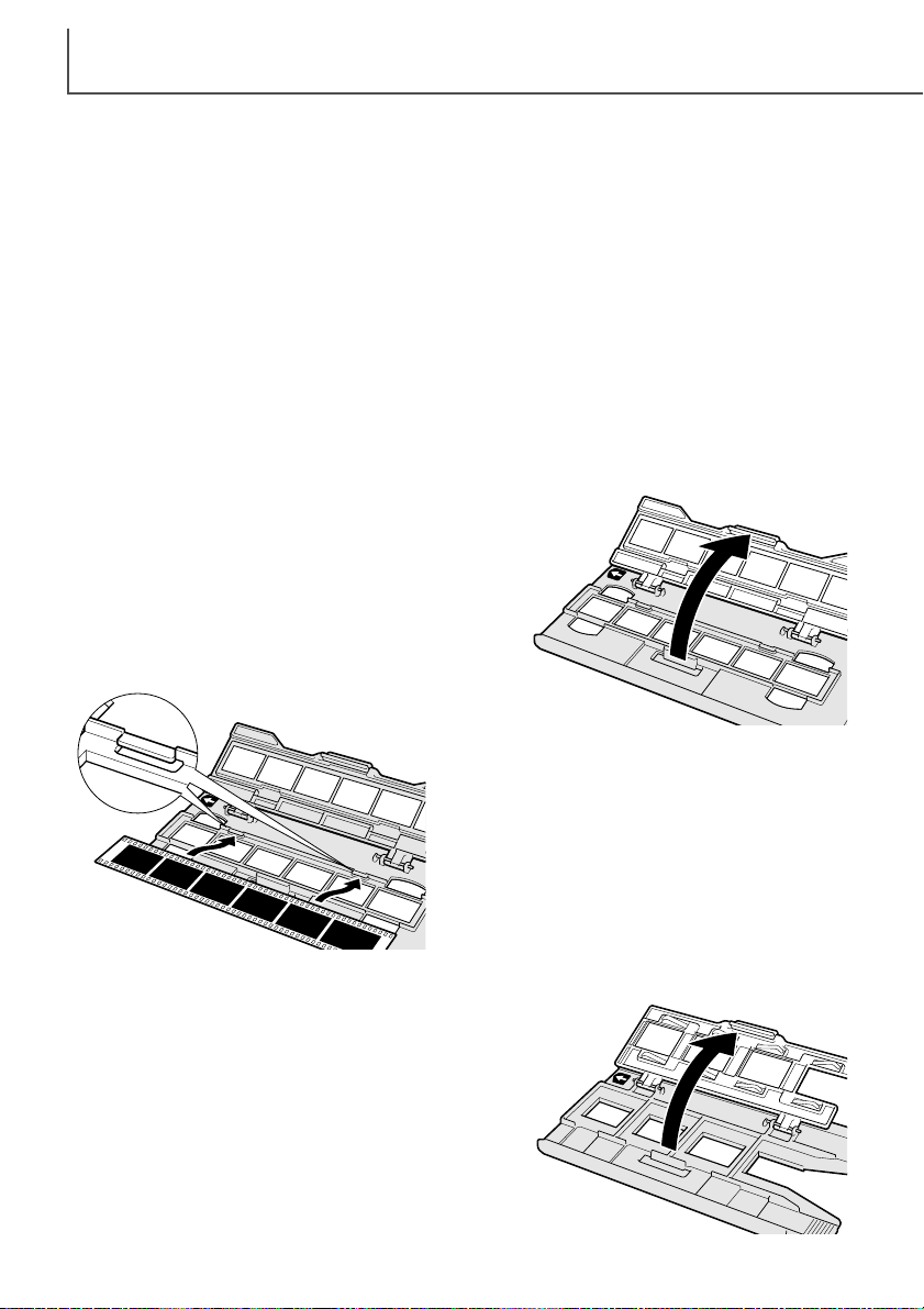
Loading 35mm film strips
The 35mm Film Holder FH-P1 is for unmounted 35mm
film. Film strips up to six frames in length can be placed
in the holder.
With the cover hinges away from you, open the holder by
lifting on the latch on the cover.
With the emulsion down, place the film sideways
into the holder and under the retaining tabs (1).
Align the film frames with the holder windows.
Carefully close the cover until the latch clicks. See
page 15 for instructions on how to load the holder
into the scanner.
1
Where is the emulsion?
When film is scanned, the emulsion side of the film should be down. When viewing the film image,
if the image is orientated correctly rather than a mirror image, the emulsion side is facing down. If
the image is abstract or symmetrical so its orientation is difficult to determine, the emulsion is
down if the frame numbers and edge markings can be read correctly. With mounted slides, the
emulsion is on the same side of the mount as the film manufacturer's or processor’s name is
printed.
Page 11

11
With the emulsion down, place the slide mounts
sideways into the holder. The mount must be
oriented as illustrated otherwise the top and
bottom of the image will be cropped.
Carefully close the cover until the latch clicks.
See page 15 for instructions on how to load the
holder into the scanner.
When the slide mount holder is in the scanner, the
last slide can be removed and a new slide inserted
without ejecting the holder. A prescan should be
made each time a slide is inserted when using the
scanner’s autofocus and auto exposure functions,
see the DiMAGE Scan Utility manual.
Inserting attachments into the Universal Holder
The Universal Holder is used for scanning medium format film. All standard formats from 6X4.5 to
6X9 can be scanned. Two attachments with and without glass are supplied with the holder. An
attachment must be inserted to hold the film.
With the hinge to the top, slide the left side of
the attachment into the holder so the two protrusions on the attachment are aligned to the
two slots in the Universal Holder.
Carefully press the right side of the attachment down until the latch in the Universal
Holder clicks.
To remove an attachment, slide the latch (1)
and lift the attachment from the front right corner.
1
Page 12

Using the glassless attachment
The glassless attachment allows scans without any
extra glass surfaces in the optical path. See page
11 for instructions on how to insert the attachment
into the Universal Holder.
LOADING THE FILM HOLDERS
12
Using the standard attachment
The standard attachment is equipped with glass to hold the film flat. A set of five masks are provided for standard formats: 6X4.5, 6X6, 6X7, 6X8, and 6X9. See page 11 for instructions on how
to insert the attachment into the Universal Holder.
To open, press the latch on the attachment and lift the cover.
Slide the tabs of the appropriate mask
into the corresponding slots on each side
of the attachment hinge. Fit the holes on
the other side of the mask (1) over the
registration pins (2) on the base of the
attachment. Always use a mask when
scanning or newton rings and flare may
degrade the image quality.
With the emulsion down, place the film on the mask.
Align the frame with the mask aperture.
Carefully close the cover until the latch clicks. See
page 15 for instructions on how to load the holder
into the scanner.
To open, press the latch on the attachment and lift the cover.
Adjust the masking bars on the attachment to the film format. White markings
indicate the format positions: 6X4.5, 6X6,
6X7, 6X8, and 6X9.
1
2
Page 13

13
Multi-format Set HS-P1 (sold separately)
The multi-format attachment allows non-standard
film sizes to be scanned. The set includes the
multi-format attachment cover (1), the multi-format
attachment base (2), and a set of three masks
(FM-P2)(3).
With the emulsion down, place the film on the
attachment. Align the frame with the attachment
aperture.
Carefully close the cover until the latch clicks. See
page 15 for instructions on how to load the holder
into the scanner.
1
2
3
Slide the left side of the attachment base into
the Universal Holder so the two protrusions on
the attachment are aligned to the two slots in
the holder.
Carefully press the right side of the base down
until the latch in the Universal Holder clicks.
Insert the two pin on the attachment cover into
the two corresponding holes in the Universal
Holder. Both pins should click into place.
The Multi-format attachment is designed for non-standard film sizes, special technical films, and
non-photographic transparent media. The maximum area that can be scanned at one time is
56.58 mm X 83.82 mm. This attachment can be used for 16 mm film, microfilm, or 24 X 65 mm
panoramic images. TEM (transmission electron microscopy) film can also be scanned. However,
since the image area of some TEM films is larger than the holder aperture, several scans need to
be made and then the image must be reconstructed digitally.
Page 14

LOADING THE FILM HOLDERS
14
With a straight edge and sharp knife, cut the aperture for
the film from one of the masks. The aperture should be
the same dimensions as the image area, not the film size;
the mask should separate the film from the glass base of
the attachment to prevent newton rings, and the aperture
should only show the image area to eliminate flare from
the surrounding clear film.
Slide the tab of the mask into the slot
on the side of the Universal Holder.
Fit the holes on the other side of the
mask (2) over the registration pins on
the base of the the holder on each
side of the cover hinges.
With the emulsion down, place the film on the
mask. Align the image area with the mask aperture.
Carefully close the cover until the latch clicks. See
page 15 for instructions on how to load the holder
into the scanner.
1
To remove the film, slide the latch toward the
center of the holder and lift the cover.
4
To remove the glass base of the attachment, slide
the latch on the Universal Holder (4) and lift the
base from the holder.
To remove the multi-format attachment from the
Universal Holder, slide the latch near the hinge (3)
to remove the cover.
3
2
Page 15

15
Ejecting a film holder
Use the eject button on the scanner body or in
the DiMAGE Scan Utility window to remove the
holder; the scanner automatically ejects the
holder to its initial insertion position. Do not
touch or hinder the holder while it is moving.
When the indicator lamp goes out, remove the
holder from the scanner.
Do not insert the film holder into the scanner while
the DiMAGE Scan Utility is launching or the scanner is initializing (the indicator lamp blinks during
this period).
Loading a film holder into the scanner
Before using the scanner, install the DiMAGE Scan Utility; see the software instruction manual.
Tu rn on the scanner and then start the computer. Launch the DiMAGE Scan Utility before inserting the film holder.
Insert the film holder into the scanner in the direction
indicated by the white arrow. Hold the holder straight
and level when inserting it into the scanner.
Carefully push the holder into the
scanner until the arrow mark (1) is
aligned with the scanner door; the
holder will be automatically fed into
the scanner from that point. Never
touch or hinder the holder while it is
moving.
1
Eject
button
Page 16

SCANNER NOTES
16
Film format and type settings
When scanning, the film type and format as well as the holder type must be selected in the main
window of the DiMAGE Scan Utility. See scanner setup in the basic-scanning section of the software manual.
When using the Slide Mount Holder SH-P1 or the 35 mm Film Holder FH-P1, select the 35 mm
option from the film-format drop-down menu. When scanning medium-format film with the standard or glassless attachment in the universal holder,
select the appropriate format from the drop-down
menu: 6 X 4.5, 6 X 6, 6 X 7, 6 X 8, or 6 X 9. When
using the optional Multi-format attachment HS-P1, two
menu options are available depending on the film
used: Multi Format 35mm and Multi Format 6X9. The
type of holder must also be specified between glass
and glassless from the holder-type drop-down menu
when the Universal Holder is used.
Film type can be selected between color and black
and white, positive and negative film. Film for prints is
negative film. Slide film is positive film. The transparent-media option is for use with the optional Multi-format attachment when scanning specialized
film or non-photographic originals such as microfilm or microscope slides. Also for the Multi-format
attachment, the TEM film option is for transmission electron microscopy film.
Disconnecting the scanner
SCSI cable
The scanner and computer must be turned off before the SCSI cable can be disconnected. If the
scanner is connected to a SCSI chain, all the devices in the chain must be turned off before disconnecting the cable.
IEEE 1394 (FireWire) cable
The easiest and safest way to disconnect the scanner from the computer is to turn both devices
off as well as any peripheral devices and remove the cable. However, the following procedures
can be used depending on the operating system employed.
Easy Scan Utility
The Easy Scan Utility software is a simple scanning interface designed for individuals with no
image processing or DTP experience. This software is not compatible with this scanner. The
DiMAGE Scan Utility’s custom wizard can be used to automate the scanning workflow, see the
software instruction manual.
About the DiMAGE Scan Utility
Prescan size can be selected in the preferences dialog box with this scanner model. See setting
scanner preferences in the advanced scanning section of the DiMAGE Scan Utility manual.
Page 17

17
Quit the DiMAGE Scan Utility. Confirm that the scanner indicator lamp is not blinking. Turn the
scanner off and then disconnect the cable.
Windows 98, 98SE, 2000 professional, XP, and Macintosh
Windows Me
To disconnect the scanner, quit the DiMAGE Scan Utility. Left click on the unplug-oreject-hardware icon located on the task bar. A small window will open indicating the
device to be stopped.
Click on the small window to stop the
device. The safe-to-remove-hardware
window will appear. Click OK. Turn the
scanner off and then disconnect the
cable.
When more than one external device are connected to
the computer, repeat the procedure above except right
click on the unplug-or-eject-hardware icon. This will open
the unplug-or-eject-hardware window after clicking on the
small window indicating the unplug operation.
On the unplug-or-eject-hardware window, the hardware
devices to be stopped will be displayed. Highlight the
device by clicking on it then click the stop button.
A confirmation screen will open to indicate the device to be stopped. Click the
OK button to stop the device.
A third and final screen will appear to
indicate the scanner can be safely disconnected from the computer; click OK.
Tu rn the scanner off and then disconnect
the cable.
Page 18

SCANNER NOTES
18
Digital ICE3system requirements
Digital ICE3is a collection of powerful image-processing tools. To make use of the Digital ROC
and GEM functions, the following system requirements must be met:
Format
Interface
35 mm
Multi-format 35 mm
6 X 9
SCSI
IEEE 1394
Color
depth
8 bit
Minimum system requirements
CPU
Pentium 166MHz or later
RAM
128MB
Hard disk space
1.2GB
35 mm
Multi-format 35 mm
6 X 9
35 mm
Multi-format 35 mm
6 X 9
35 mm
Multi-format 35 mm
6 X 9
16 bit
8 bit
16 bit
Pentium II or later
256MB
128MB
256MB
PC/AT compatible computers
2GB
4GB
2GB
3GB
6GB
1.2GB
2GB
4GB
2GB
3GB
6GB
Recommended system requirements
35 mm
Multi-format 35 mm
6 X 9
SCSI
or
IEEE 1394
8 bit
Pentium III or later
2GB
35 mm
Multi-format 35 mm
6 X 9
16 bit
512MB
4GB
6GB
3GB
4GB
8GB
Macintosh computers
When determining the RAM available for a Macintosh computer, the volume required for the operating system and any application in use must be subtracted from the total memory allocation of
the computer.
35 mm
Multi-format 35 mm
6 X 9
SCSI
or
FireWire
8 bit
PowerPC 604 or later
(SCSI)
PowerPC G3 or later
(FireWire)
96MB1.2GB
35 mm
Multi-format 35 mm
6 X 9
16 bit
192MB
2GB
4GB
2GB
3GB
6GB
Recommended system requirements
35 mm
Multi-format 35 mm
6 X 9
8 bit
PowerPC G4 or later
2GB
35 mm
Multi-format 35 mm
6 X 9
16 bit
512MB
4GB
6GB
3GB
4GB
8GB
256MB
384MB
Page 19

19
Scanner color profiles
When the DiMAGE Scan Utility is installed, the scanner profiles listed below are automatically
installed for this model scanner.These profiles have been included for advanced color matching
with profile-to-profile conversions in sophisticated image-processing or DTP applications. When
using these profiles, the color reproduced may not be the same as the color matching system in
the utility software.
MLTF5000.icc - used with positive film at any color depth other than 16-bit linear.
MLTF5000p.icc - used with positive film with 16-bit linear color depth.
The profiles are located in the following locations:
Scanner resolution
The maximum resolution of this scanner is 4800 X 4800 dpi. The maximum optical resolution
varies with the format of the film: 35 mm film - 4800 X 4800, medium-format film - 3200 X 4800.
Scans of medium-format film can have a final resolution of 4800 X 4800 dpi through interpolation.
The minimum resolution is 300 dpi for 35mm and 200 dpi for medium-format film.
System32 Drivers
System
Mac OS (8, 9)
ColorSync profile
MLTF5000.icc
MLTF5000p.icc
Mac OS X
Users
(User logon
name)
Library ColorSync Profiles
WINNT
Windows (2000)
Spool Color
System32 DriversWindows
Windows (XP)
Spool Color
Windows (98, 98SE, Me)
Windows System Color
Page 20

JOB FILE LISTS
20
35mm
Jobs can be used to make scan settings based on the final use of the image. See making-thefinal-scan section in the DiMAGE Scan Utility manual. The following charts list the parameters of
the scanner’s Job files:
Category Job name Input res. Output res. Mag. Unit Lock (input) Output size Lock (output)
4800 37.08 25.02 7008 4728
Default Default 1200 300 400 pixel 1752 1182 OFF 1752 1182 OFF 1752 1182
ColorLaserPrinter A4Full 4800 600 800 mm 35.38 25.02 OFF 283 200.152 ON 6685 4728
Photosensitive A3Full 4749 400 1187 mm 35.38 25.02 OFF 420 297 ON 6614 4677
Ink-Jet & SuperB 3945 300 1315 mm 36.73 25.02 OFF 483 329 ON 5704 3885
Dye-SubPrinter A3Full 3561 300 1187 mm 35.38 25.02 OFF 420 297 ON 4960 3507
WebPage 1240x836 850 72 1180 pixel 1240 836 OFF 1240 836 ON 1240 836
PhotoCD PhotoCD2048x3072 2105 300 701 pixel 3072 2048 OFF 3072 2048 ON 3072 2048
Screen 1920x1200 1316 72 1827 pixel 1920 1200 OFF 1920 1200 ON 1920 1200
Document A4Half 426 72 591 mm 35.53 25.04 OFF 210 148 ON 595 419
FilmRecorder 4K 2806 2400 116 pixel 4096 2731 OFF 4096 2731 ON 4096 2731
A4Half 3550 600 591 mm 35.53 25.04 OFF 210 148 ON 4960 3496
A4Quarter 2518 600 419 mm 35.32 25.06 OFF 148 105 ON 3496 2480
LetterFull 4800 600 800 inch 1.26 0.99 OFF 10.1 7.88 ON 6060 4728
LetterHalf 3494 600 582 inch 1.46 0.94 OFF 8.5 5.45 ON 5100 3270
LetterQuarter 2589 600 431 inch 1.26 0.99 OFF 5.45 4.25 ON 3270 2550
A4Full 3358 400 839 mm 35.4 25.03 OFF 297 210 ON 4677 3307
A5Full 2366 400 591 mm 35.53 25.04 OFF 210 148 ON 3307 2330
LetterFull 3452 400 863 inch 1.26 0.99 OFF 10.9 8.5 ON 4360 3400
LetterHalf 2329 400 582 inch 1.46 0.94 OFF 8.5 5.45 ON 3400 2180
LetterQuarter 1726 400 431 inch 1.26 0.99 OFF 5.45 4.25 ON 2180 1700
8x10 3249 400 812 inch 1.23 0.99 OFF 10 8 ON 4000 3200
11x14 4460 400 1115 mm 31.93 25.02 OFF 356 279 ON 5606 4393
10x12 4061 400 1015 mm 30.05 25.02 OFF 305 254 ON 4803 4000
2L 2031 400 507 mm 35.11 25.05 OFF 178 127 ON 2803 2000
PostCard4x6 1644 400 411 inch 1.46 0.97 OFF 6 4 ON 2400 1600
A4Full 2518 300 839 mm 35.4 25.03 OFF 297 210 ON 3507 2480
A4Half 1775 300 591 mm 35.53 25.04 OFF 210 148 ON 2480 1748
A4Quarter 1259 300 419 mm 35.32 25.06 OFF 148 105 ON 1748 1240
LetterFull 2589 300 863 inch 1.26 0.99 OFF 10.9 8.5 ON 3270 2550
LetterHalf 1747 300 582 inch 1.46 0.94 OFF 8.5 5.45 ON 2550 1635
LetterQuarter 1295 300 431 inch 1.26 0.99 OFF 5.45 4.25 ON 1635 1275
Photo4x6 1214 300 404 mm 37.13 24.75 OFF 150 100 ON 1771 1181
Photo3x5 1068 300 356 mm 35.67 25 OFF 127 89 ON 1500 1051
1112x750 762 72 1058 pixel 1112 750 OFF 1112 750 ON 1112 750
984x663 674 72 936 pixel 984 663 OFF 984 663 ON 984 663
792x534 543 72 754 pixel 792 534 OFF 792 534 ON 792 534
760x512 521 72 723 pixel 760 512 OFF 760 512 ON 760 512
600x404 411 72 570 pixel 600 404 OFF 600 404 ON 600 404
320x240 300 72 416 pixel 320 240 OFF 320 240 ON 320 240
PhotoCD1024x1536 1053 300 351 pixel 1536 1024 OFF 1536 1024 ON 1536 1024
PhotoCD512x768 527 300 175 pixel 768 512 OFF 768 512 ON 768 512
1600x1200 1219 72 1693 pixel 1600 1200 OFF 1600 1200 ON 1600 1200
1280x1024 1040 72 1444 pixel 1280 1024 OFF 1280 1024 ON 1280 1024
1280x960 975 72 1354 pixel 1280 960 OFF 1280 960 ON 1280 960
1152x870 884 72 1227 pixel 1152 870 OFF 1152 870 ON 1152 870
1024x768 780 72 1083 pixel 1024 768 OFF 1024 768 ON 1024 768
832x624 837 72 1162 pixel 832 824 OFF 832 824 ON 832 824
800x600 610 72 847 pixel 800 600 OFF 800 600 ON 800 600
640x480 488 72 677 pixel 640 480 OFF 640 480 ON 640 480
A4Quarter 302 72 419 mm 35.32 25.06 OFF 148 105 ON 419 297
A4Eighth 300 72 416 mm 25.24 17.79 OFF 105 74 ON 297 209
LetterHalf 420 72 583 inch 1.46 0.93 OFF 8.5 5.45 ON 612 392
LetterQuarter 311 72 431 inch 1.26 0.99 OFF 5.45 4.25 ON 392 306
LetterEighth 300 72 416 inch 1.02 0.65 OFF 4.25 2.72 ON 306 195
2K 1403 2400 58 pixel 2048 1365 OFF 2048 1365 ON 2048 1365
Input size Input pixels
WH WH W H
1.460 0.985
Page 21

21
6 X 4.5
Category Job name Input res. Output res. Mag. Unit Lock (input) Output size Lock (output)
3200 42.67 56.58 5376 7128
Default Default 800 300 266 pixel 1344 1782 OFF 1344 1782 OFF 1344 1782
ColorLaserPrinter A3Full 4454 600 742 mm 40.03 56.6 OFF 297 420 ON 7015 9921
Photosensitive A3Full 2970 400 742 mm 40.03 56.6 OFF 297 420 ON 4677 6614
Ink-Jet & SuperB 2561 300 853 mm 38.57 56.62 OFF 329 483 ON 3885 5704
Dye-SubPrinter A3Full 2227 300 742 mm 40.03 56.6 OFF 297 420 ON 3507 4960
WebPage 1240x935 557 72 773 pixel 935 1240 OFF 935 1240 ON 935 1240
PhotoCD PhotoCD2048x3072 1380 300 460 pixel 2048 3072 OFF 2048 3072 ON 2048 3072
Screen 1920x1200 862 72 1197 pixel 1200 1920 OFF 1200 1920 ON 1200 1920
Document A4Half 268 72 372 mm 39.79 56.45 OFF 148 210 ON 419 595
A4Full 3150 600 525 mm 40 56.57 OFF 210 297 ON 4960 7015
A4Half 2227 600 371 mm 39.89 56.6 OFF 148 210 ON 3496 4960
A4Quarter 1570 600 261 mm 40.23 56.71 OFF 105 148 ON 2480 3496
LetterFull 3036 600 506 inch 1.68 2.15 OFF 8.5 10.9 ON 5100 6540
LetterHalf 2290 600 381 inch 1.43 2.23 OFF 5.45 8.5 ON 3270 5100
LetterQuarter 1518 600 253 inch 1.68 2.15 OFF 4.25 5.45 ON 2550 3270
A4Full 2100 400 525 mm 40 56.57 OFF 210 297 ON 3307 4677
A5Full 1485 400 371 mm 39.89 56.6 OFF 148 210 ON 2330 3307
LetterFull 2024 400 506 inch 1.68 2.15 OFF 8.5 10.9 ON 3400 4360
LetterHalf 1527 400 381 inch 1.43 2.23 OFF 5.45 8.5 ON 2180 3400
LetterQuarter 1012 400 253 inch 1.68 2.15 OFF 4.25 5.45 ON 1700 2180
8x10 1905 400 476 inch 1.68 2.1 OFF 8 10 ON 3200 4000
11x14 2615 400 653 mm 42.73 54.52 OFF 279 356 ON 4393 5606
10x12 2381 400 595 mm 42.69 51.26 OFF 254 305 ON 4000 4803
2L 1259 400 314 mm 38.22 56.69 OFF 120 178 ON 1889 2803
PostCard4x6 1078 400 269 inch 1.49 2.23 OFF 4 6 ON 1600 2400
A4Full 1575 300 525 mm 40 56.57 OFF 210 297 ON 2480 3507
A4Half 1114 300 371 mm 39.89 56.6 OFF 148 210 ON 1748 2480
A4Quarter 785 300 261 mm 40.23 56.71 OFF 105 148 ON 1240 1748
LetterFull 1518 300 506 inch 1.68 2.15 OFF 8.5 10.9 ON 2550 3270
LetterHalf 1145 300 381 inch 1.43 2.23 OFF 5.45 8.5 ON 1635 2550
LetterQuarter 759 300 253 inch 1.68 2.15 OFF 4.25 5.45 ON 1275 1635
Photo4x6 796 300 265 mm 37.74 56.6 OFF 100 150 ON 1181 1771
Photo3x5 674 300 224 mm 39.73 56.7 OFF 89 127 ON 1051 1500
1112x839 500 72 694 pixel 839 1112 OFF 839 1112 ON 839 1112
984x742 442 72 613 pixel 742 984 OFF 742 984 ON 742 984
792x597 356 72 494 pixel 597 792 OFF 597 792 ON 597 792
760x573 342 72 475 pixel 573 760 OFF 573 760 ON 573 760
600x452 270 72 375 pixel 452 600 OFF 452 600 ON 452 600
320x240 200 72 277 pixel 240 320 OFF 240 320 ON 240 320
PhotoCD1024x1536 690 300 230 pixel 1024 1536 OFF 1024 1536 ON 1024 1536
PhotoCD512x768 345 300 115 pixel 512 768 OFF 512 768 ON 512 768
1600x1200 719 72 998 pixel 1200 1600 OFF 1200 1600 ON 1200 1600
1280x1024 610 72 847 pixel 1024 1280 OFF 1024 1280 ON 1024 1280
1280x960 575 72 798 pixel 960 1280 OFF 960 1280 ON 960 1280
1152x870 518 72 719 pixel 870 1152 OFF 870 1152 ON 870 1152
1024x768 460 72 638 pixel 768 1024 OFF 768 1024 ON 768 1024
832x624 374 72 519 pixel 624 832 OFF 624 832 ON 624 832
800x600 360 72 500 pixel 600 800 OFF 600 800 ON 600 800
640x480 288 72 400 pixel 480 640 OFF 480 640 ON 480 640
A4Quarter 200 72 277 mm 37.91 53.43 OFF 105 148 ON 297 419
A4Eighth 200 72 277 mm 26.71 37.91 OFF 74 105 ON 209 297
LetterHalf 275 72 381 inch 1.43 2.23 OFF 5.45 8.5 ON 392 612
LetterQuarter 200 72 277 inch 1.53 1.97 OFF 4.25 5.45 ON 306 392
LetterEighth 200 72 277 inch 0.98 1.53 OFF 2.72 4.25 ON 195 306
Input size Input pixels
WH WH WH
1.68 2.23
Page 22

JOB FILE LISTS
22
6 X 6
Category Job name Input res. Output res. Mag. Unit Lock (input) Output size Lock (output)
3200 56.58 56.58 7128 7128
Default Default 800 300 266 pixel 1782 1782 OFF 1782 1782 OFF 1782 1782
ColorLaserPrinter A3Full 3150 600 525 mm 56.57 56.57 OFF 297 297 ON 7015 7015
Photosensitive A3Full 2100 400 525 mm 56.57 56.57 OFF 297 297 ON 4677 4677
Ink-Jet & SuperB 1745 300 581 mm 56.63 56.63 OFF 329 329 ON 3885 3885
Dye-SubPrinter A3Full 1575 300 525 mm 56.57 56.57 OFF 297 297 ON 3507 3507
WebPage 1240x1240 557 72 773 pixel 1240 1240 OFF 1240 1240 ON 1240 1240
PhotoCD PhotoCD2048x3072 1380 300 460 pixel 3072 2048 OFF 3072 2048 ON 3072 2048
Screen 1920x1200 862 72 1197 pixel 1920 1200 OFF 1920 1200 ON 1920 1200
Document A4Half 200 72 277 mm 53.43 53.43 OFF 148 148 ON 419 419
A4Full 2227 600 371 mm 56.6 56.6 OFF 210 210 ON 4960 4960
A4Half 1570 600 261 mm 56.71 56.71 OFF 148 148 ON 3496 3496
A4Quarter 1114 600 185 mm 56.76 56.76 OFF 105 105 ON 2480 2480
LetterFull 2290 600 381 inch 2.23 2.23 OFF 8.5 8.5 ON 5100 5100
LetterHalf 1469 600 244 inch 2.23 2.23 OFF 5.45 5.45 ON 3270 3270
LetterQuarter 1145 600 190 inch 2.24 2.24 OFF 4.25 4.25 ON 2550 2550
A4Full 1485 400 371 mm 56.6 56.6 OFF 210 210 ON 3307 3307
A5Full 1047 400 261 mm 56.71 56.71 OFF 148 148 ON 2330 2330
LetterFull 1527 400 381 inch 2.23 2.23 OFF 8.5 8.5 ON 3400 3400
LetterHalf 979 400 244 inch 2.23 2.23 OFF 5.45 5.45 ON 2180 2180
LetterQuarter 764 400 191 inch 2.23 2.23 OFF 4.25 4.25 ON 1700 1700
8x10 1437 400 359 inch 2.23 2.23 OFF 8 8 ON 3200 3200
14x17 2517 400 629 mm 56.6 56.6 OFF 356 356 ON 5606 5606
11x14 1973 400 493 mm 56.59 56.59 OFF 279 279 ON 4393 4393
10x12 1796 400 449 mm 56.57 56.57 OFF 254 254 ON 4000 4000
2L 898 400 224 mm 56.7 56.7 OFF 127 127 ON 2000 2000
PostCard4x6 719 400 179 inch 2.23 2.23 OFF 4 4 ON 1600 1600
A4Full 1114 300 371 mm 56.6 56.6 OFF 210 210 ON 2480 2480
A4Half 785 300 261 mm 56.71 56.71 OFF 148 148 ON 1748 1748
A4Quarter 557 300 185 mm 56.76 56.76 OFF 105 105 ON 1240 1240
LetterFull 1145 300 381 inch 2.23 2.23 OFF 8.5 8.5 ON 2550 2550
LetterHalf 735 300 245 inch 2.22 2.22 OFF 5.45 5.45 ON 1635 1635
LetterQuarter 573 300 191 inch 2.23 2.23 OFF 4.25 4.25 ON 1275 1275
Photo4x6 531 300 177 mm 56.5 56.5 OFF 100 100 ON 1181 1181
Photo3x5 472 300 157 mm 56.69 56.69 OFF 89 89 ON 1051 1051
1112x1112 500 72 694 pixel 1112 1112 OFF 1112 1112 ON 1112 1112
984x984 442 72 613 pixel 984 984 OFF 984 984 ON 984 984
792x792 356 72 494 pixel 792 792 OFF 792 792 ON 792 792
760x760 342 72 475 pixel 760 760 OFF 760 760 ON 760 760
600x600 270 72 375 pixel 600 600 OFF 600 600 ON 600 600
320x240 200 72 277 pixel 320 240 OFF 320 240 ON 320 240
PhotoCD1024x1536 690 300 230 pixel 1536 1024 OFF 1536 1024 ON 1536 1024
PhotoCD512x768 345 300 115 pixel 768 512 OFF 768 512 ON 768 512
1600x1200 719 72 998 pixel 1600 1200 OFF 1600 1200 ON 1600 1200
1280x1024 575 72 798 pixel 1280 1024 OFF 1280 1024 ON 1280 1024
1280x960 575 72 798 pixel 1280 960 OFF 1280 960 ON 1280 960
1152x870 518 72 719 pixel 1152 870 OFF 1152 870 ON 1152 870
1024x768 460 72 638 pixel 1024 768 OFF 1024 768 ON 1024 768
832x624 374 72 519 pixel 832 624 OFF 832 624 ON 832 624
800x600 360 72 500 pixel 800 600 OFF 800 600 ON 800 600
640x480 288 72 400 pixel 640 480 OFF 640 480 ON 640 480
A4Quarter 200 72 277 mm 37.91 37.91 OFF 105 105 ON 297 297
A4Eighth 200 72 277 mm 26.71 26.71 OFF 74 74 ON 209 209
LetterHalf 200 72 277 inch 1.97 1.97 OFF 5.45 5.45 ON 392 392
LetterQuarter 200 72 277 inch 1.53 1.53 OFF 4.25 4.25 ON 306 306
LetterEighth 200 72 277 inch 0.97 0.97 OFF 2.69 2.69 ON 193 193
Input size Input pixels
WH W H WH
2.23 2.23
Page 23

23
6 X 7
Category Job name Input res. Output res. Mag. Unit Lock (input) Output size Lock (output)
3200 70.10 56.58 8832 7128
Default Default 800 300 266 pixel 2208 1782 OFF 2208 1782 OFF 2208 1782
ColorLaserPrinter A3Full 3595 600 599 mm 70.12 49.58 OFF 420 297 ON 9921 7015
Photosensitive A3Full 2397 400 599 mm 70.12 49.58 OFF 420 297 ON 6614 4677
Ink-Jet & SuperB 2756 400 689 mm 70.1 47.75 OFF 483 329 ON 7606 5181
Dye-SubPrinter A3Full 2397 400 599 mm 70.12 49.58 OFF 420 297 ON 6614 4677
WebPage 1240x1000 450 72 625 pixel 1240 1000 OFF 1240 1000 ON 1240 1000
PhotoCD PhotoCD2048x3072 1114 300 371 pixel 3072 2048 OFF 3072 2048 ON 3072 2048
Screen 1920x1200 696 72 966 pixel 1920 1200 OFF 1920 1200 ON 1920 1200
Document A4Half 215 72 298 mm 70.13 49.33 OFF 209 147 ON 592 416
A4Full 2542 600 423 mm 70.21 49.65 OFF 297 210 ON 7015 4960
A4Half 1798 600 299 mm 70.23 49.5 OFF 210 148 ON 4960 3496
A4Quarter 1267 600 211 mm 70.14 49.76 OFF 148 105 ON 3496 2480
LetterFull 2370 600 395 inch 2.76 2.15 OFF 10.9 8.5 ON 6540 5100
LetterHalf 1848 600 308 inch 2.76 1.77 OFF 8.5 5.45 ON 5100 3270
LetterQuarter 1185 600 197 inch 2.77 2.16 OFF 5.45 4.25 ON 3270 2550
A4Full 1695 400 423 mm 70.21 49.65 OFF 297 210 ON 4677 3307
A5Full 1199 400 299 mm 70.23 49.5 OFF 210 148 ON 3307 2330
LetterFull 1580 400 395 inch 2.76 2.15 OFF 10.9 8.5 ON 4360 3400
LetterHalf 1232 400 308 inch 2.76 1.77 OFF 8.5 5.45 ON 3400 2180
LetterQuarter 790 400 197 inch 2.77 2.16 OFF 5.45 4.25 ON 2180 1700
8x10 1450 400 362 inch 2.76 2.21 OFF 10 8 ON 4000 3200
14x17 2517 400 629 mm 68.68 56.6 OFF 432 356 ON 6803 5606
11x14 2032 400 508 mm 70.08 54.92 OFF 356 279 ON 5606 4393
10x12 1796 400 449 mm 67.93 56.57 OFF 305 254 ON 4803 4000
2L 1016 400 254 mm 70.08 50 OFF 178 127 ON 2803 2000
PostCard4x6 870 400 217 inch 2.77 1.84 OFF 6 4 ON 2400 1600
A4Full 1271 300 423 mm 70.21 49.65 OFF 297 210 ON 3507 2480
A4Half 899 300 299 mm 70.23 49.5 OFF 210 148 ON 2480 1748
A4Quarter 634 300 211 mm 70.14 49.76 OFF 148 105 ON 1748 1240
LetterFull 1185 300 395 inch 2.76 2.15 OFF 10.9 8.5 ON 3270 2550
LetterHalf 924 300 308 inch 2.76 1.77 OFF 8.5 5.45 ON 2550 1635
LetterQuarter 593 300 197 inch 2.77 2.16 OFF 5.45 4.25 ON 1635 1275
Photo4x6 642 300 214 mm 70.09 46.73 OFF 150 100 ON 1771 1181
Photo3x5 544 300 181 mm 70.17 49.17 OFF 127 89 ON 1500 1051
1112x897 403 72 559 pixel 1112 897 OFF 1112 897 ON 1112 897
984x794 357 72 495 pixel 984 794 OFF 984 794 ON 984 794
792x639 287 72 398 pixel 792 639 OFF 792 639 ON 792 639
760x613 276 72 383 pixel 760 613 OFF 760 613 ON 760 613
600x484 218 72 302 pixel 600 484 OFF 600 484 ON 600 484
320x240 200 72 277 pixel 320 240 OFF 320 240 ON 320 240
PhotoCD1024x1536 557 300 185 pixel 1536 1024 OFF 1536 1024 ON 1536 1024
PhotoCD512x768 279 300 93 pixel 768 512 OFF 768 512 ON 768 512
1600x1200 580 72 805 pixel 1600 1200 OFF 1600 1200 ON 1600 1200
1280x1024 464 72 644 pixel 1280 1024 OFF 1280 1024 ON 1280 1024
1280x960 464 72 644 pixel 1280 960 OFF 1280 960 ON 1280 960
1152x870 418 72 580 pixel 1152 870 OFF 1152 870 ON 1152 870
1024x768 372 72 516 pixel 1024 768 OFF 1024 768 ON 1024 768
832x624 302 72 419 pixel 832 624 OFF 832 624 ON 832 624
800x600 290 72 402 pixel 800 600 OFF 800 600 ON 800 600
640x480 232 72 322 pixel 640 480 OFF 640 480 ON 640 480
A4Quarter 200 72 277 mm 53.07 37.55 OFF 147 104 ON 416 294
A4Eighth 200 72 277 mm 37.55 26.53 OFF 104 73.5 ON 294 208
LetterHalf 222 72 308 inch 2.76 1.77 OFF 8.5 5.45 ON 612 392
LetterQuarter 200 72 277 inch 1.97 1.53 OFF 5.45 4.25 ON 392 306
LetterEighth 200 72 277 inch 1.53 0.97 OFF 4.25 2.7 ON 306 194
Input size Input pixels
WH WH WH
2.76 2.23
Page 24

JOB FILE LISTS
24
6 X 8
Category Job name Input res. Output res. Mag. Unit Lock (input) Output size Lock (output)
3200 77.15 56.58 9720 7128
Default Default 800 300 266 pixel 2430 1782 OFF 2430 1782 OFF 2430 1782
ColorLaserPrinter A3Full 3200 600 533 mm 77.2 55.72 OFF 411.48 297 ON 9720 7015
Photosensitive A3Full 2178 400 544 mm 77.21 54.6 OFF 420 297 ON 6614 4677
Ink-Jet & SuperB 1878 300 626 mm 77.16 52.56 OFF 483 329 ON 5704 3885
Dye-SubPrinter A3Full 1633 300 544 mm 77.21 54.6 OFF 420 297 ON 4960 3507
WebPage 1240x909 409 72 568 pixel 1240 909 OFF 1240 909 ON 1240 909
PhotoCD PhotoCD2048x3072 1012 300 337 pixel 3072 2048 OFF 3072 2048 ON 3072 2048
Screen 1920x1200 633 72 879 pixel 1920 1200 OFF 1920 1200 ON 1920 1200
Document A4Half 200 72 277 mm 75.81 53.43 OFF 210 148 ON 595 419
A4Full 2310 600 385 mm 77.14 54.55 OFF 297 210 ON 7015 4960
A4Half 1633 600 272 mm 77.21 54.41 OFF 210 148 ON 4960 3496
A4Quarter 1151 600 191 mm 77.49 54.97 OFF 148 105 ON 3496 2480
LetterFull 2290 600 381 inch 2.86 2.23 OFF 10.9 8.5 ON 6540 5100
LetterHalf 1680 600 280 inch 3.04 1.95 OFF 8.5 5.45 ON 5100 3270
LetterQuarter 1145 600 190 inch 2.87 2.24 OFF 5.45 4.25 ON 3270 2550
A4Full 1540 400 385 mm 77.14 54.55 OFF 297 210 ON 4677 3307
A5Full 1089 400 272 mm 77.21 54.41 OFF 210 148 ON 3307 2330
LetterFull 1527 400 381 inch 2.86 2.23 OFF 10.9 8.5 ON 4360 3400
LetterHalf 1120 400 280 inch 3.04 1.95 OFF 8.5 5.45 ON 3400 2180
LetterQuarter 764 400 191 inch 2.85 2.23 OFF 5.45 4.25 ON 2180 1700
8x10 1437 400 359 inch 2.79 2.23 OFF 10 8 ON 4000 3200
14x17 2517 400 629 mm 68.68 56.6 OFF 432 356 ON 6803 5606
11x14 1973 400 493 mm 72.21 56.59 OFF 356 279 ON 5606 4393
10x12 1796 400 449 mm 67.93 56.57 OFF 305 254 ON 4803 4000
2L 923 400 230 mm 77.39 55.22 OFF 178 127 ON 2803 2000
PostCard4x6 791 400 197 inch 3.05 2.03 OFF 6 4 ON 2400 1600
A4Full 1155 300 385 mm 77.14 54.55 OFF 297 210 ON 3507 2480
A4Half 817 300 272 mm 77.21 54.41 OFF 210 148 ON 2480 1748
A4Quarter 576 300 192 mm 77.08 54.69 OFF 148 105 ON 1748 1240
LetterFull 1145 300 381 inch 2.86 2.23 OFF 10.9 8.5 ON 3270 2550
LetterHalf 840 300 280 inch 3.04 1.95 OFF 8.5 5.45 ON 2550 1635
LetterQuarter 573 300 191 inch 2.85 2.23 OFF 5.45 4.25 ON 1635 1275
Photo4x6 584 300 194 mm 77.32 51.55 OFF 150 100 ON 1771 1181
Photo3x5 494 300 164 mm 77.44 54.27 OFF 127 89 ON 1500 1051
1112x815 367 72 509 pixel 1112 815 OFF 1112 815 ON 1112 815
984x721 324 72 450 pixel 984 721 OFF 984 721 ON 984 721
792x580 261 72 362 pixel 792 580 OFF 792 580 ON 792 580
760x557 251 72 348 pixel 760 557 OFF 760 557 ON 760 557
600x440 200 72 277 pixel 600 440 OFF 600 440 ON 600 440
320x240 200 72 277 pixel 320 240 OFF 320 240 ON 320 240
PhotoCD1024x1536 506 300 168 pixel 1536 1024 OFF 1536 1024 ON 1536 1024
PhotoCD512x768 253 300 84 pixel 768 512 OFF 768 512 ON 768 512
1600x1200 539 72 748 pixel 1600 1200 OFF 1600 1200 ON 1600 1200
1280x1024 460 72 638 pixel 1280 1024 OFF 1280 1024 ON 1280 1024
1280x960 431 72 598 pixel 1280 960 OFF 1280 960 ON 1280 960
1152x870 391 72 543 pixel 1152 870 OFF 1152 870 ON 1152 870
1024x768 345 72 479 pixel 1024 768 OFF 1024 768 ON 1024 768
832x624 281 72 390 pixel 832 624 OFF 832 624 ON 832 624
800x600 270 72 375 pixel 800 600 OFF 800 600 ON 800 600
640x480 216 72 300 pixel 640 480 OFF 640 480 ON 640 480
A4Quarter 200 72 277 mm 53.43 37.91 OFF 148 105 ON 419 297
A4Eighth 200 72 277 mm 37.91 26.71 OFF 105 74 ON 297 209
LetterHalf 202 72 280 inch 3.04 1.95 OFF 8.5 5.45 ON 612 392
LetterQuarter 200 72 277 inch 1.97 1.53 OFF 5.45 4.25 ON 392 306
LetterEighth 200 72 277 inch 1.53 0.98 OFF 4.25 2.72 ON 306 195
Input size Input pixels
WH WH WH
3.04 2.23
Page 25

25
6 X 9 and Multi-format 6 X 9
Multi-format 35mm
Category Job name Input res. Output res. Mag. Unit Lock (input) Output size Lock (output)
3200 83.82 56.58 10560 7128
Default Default 800 300 266 pixel 2640 1782 OFF 2640 1782 OFF 2640 1782
ColorLaserPrinter A3Full 3150 600 525 mm 80 56.57 OFF 420 297 ON 9921 7015
Photosensitive A3Full 2100 400 525 mm 80 56.57 OFF 420 297 ON 6614 4677
Ink-Jet & SuperB 1745 300 581 mm 83.13 56.63 OFF 483 329 ON 5704 3885
Dye-SubPrinter A3Full 1575 300 525 mm 80 56.57 OFF 420 297 ON 4960 3507
WebPage 1240x837 376 300 125 pixel 1240 837 OFF 1240 837 ON 1240 837
PhotoCD PhotoCD2048x3072 931 300 310 pixel 3072 2048 OFF 3072 2048 ON 3072 2048
Screen 1920x1200 582 72 808 pixel 1920 1200 OFF 1920 1200 ON 1920 1200
Document A4Half 200 72 277 mm 75.81 53.43 OFF 210 148 ON 595 419
A4Full 2227 600 371 mm 80.05 56.6 OFF 297 210 ON 7015 4960
A4Half 1570 600 261 mm 80.46 56.71 OFF 210 148 ON 4960 3496
A4Quarter 1114 600 185 mm 80 56.76 OFF 148 105 ON 3496 2480
LetterFull 2290 600 381 inch 2.86 2.23 OFF 10.9 8.5 ON 6540 5100
LetterHalf 1546 600 257 inch 3.31 2.12 OFF 8.5 5.45 ON 5100 3270
LetterQuarter 1145 600 190 inch 2.87 2.24 OFF 5.45 4.25 ON 3270 2550
A4Full 1485 400 371 mm 80.05 56.6 OFF 297 210 ON 4677 3307
A5Full 1047 400 261 mm 80.46 56.71 OFF 210 148 ON 3307 2330
LetterFull 1527 400 381 inch 2.86 2.23 OFF 10.9 8.5 ON 4360 3400
LetterHalf 1031 400 257 inch 3.31 2.12 OFF 8.5 5.45 ON 3400 2180
LetterQuarter 764 400 191 inch 2.85 2.23 OFF 5.45 4.25 ON 2180 1700
8x10 1437 400 359 inch 2.79 2.23 OFF 10 8 ON 4000 3200
14x17 2517 400 629 mm 68.68 56.6 OFF 432 356 ON 6803 5606
11x14 1973 400 493 mm 72.21 56.59 OFF 356 279 ON 5606 4393
10x12 1796 400 449 mm 67.93 56.57 OFF 305 254 ON 4803 4000
2L 898 400 224 mm 79.46 56.7 OFF 178 127 ON 2803 2000
PostCard4x6 728 400 182 inch 3.3 2.2 OFF 6 4 ON 2400 1600
A4Full 1114 300 371 mm 80.05 56.6 OFF 297 210 ON 3507 2480
A4Half 785 300 261 mm 80.46 56.71 OFF 210 148 ON 2480 1748
A4Quarter 557 300 185 mm 80 56.76 OFF 148 105 ON 1748 1240
LetterFull 1145 300 381 inch 2.86 2.23 OFF 10.9 8.5 ON 3270 2550
LetterHalf 773 300 257 inch 3.31 2.12 OFF 8.5 5.45 ON 2550 1635
LetterQuarter 573 300 191 inch 2.85 2.23 OFF 5.45 4.25 ON 1635 1275
Photo4x6 537 300 179 mm 83.8 55.87 OFF 150 100 ON 1771 1181
Photo3x5 472 300 157 mm 80.89 56.69 OFF 127 89 ON 1500 1051
1112x751 338 300 112 pixel 1112 751 OFF 1112 751 ON 1112 751
984x664 299 300 99 pixel 984 664 OFF 984 664 ON 984 664
792x534 240 300 80 pixel 792 534 OFF 792 534 ON 792 534
760x513 231 300 77 pixel 760 513 OFF 760 513 ON 760 513
600x405 200 300 66 pixel 600 405 OFF 600 405 ON 600 405
320x240 200 300 66 pixel 320 240 OFF 320 240 ON 320 240
PhotoCD1024x1536 466 300 155 pixel 1536 1024 OFF 1536 1024 ON 1536 1024
PhotoCD512x768 233 300 77 pixel 768 512 OFF 768 512 ON 768 512
1600x1200 539 72 748 pixel 1600 1200 OFF 1600 1200 ON 1600 1200
1280x1024 460 72 638 pixel 1280 1024 OFF 1280 1024 ON 1280 1024
1280x960 431 72 598 pixel 1280 960 OFF 1280 960 ON 1280 960
1152x870 391 72 543 pixel 1152 870 OFF 1152 870 ON 1152 870
1024x768 345 72 479 pixel 1024 768 OFF 1024 768 ON 1024 768
832x624 281 72 390 pixel 832 624 OFF 832 624 ON 832 624
800x600 270 72 375 pixel 800 600 OFF 800 600 ON 800 600
640x480 216 72 300 pixel 640 480 OFF 640 480 ON 640 480
A4Quarter 200 72 277 mm 53.43 37.91 OFF 148 105 ON 419 297
A4Eighth 200 72 277 mm 37.91 26.71 OFF 105 74 ON 297 209
LetterHalf 200 72 277 inch 3.07 1.97 OFF 8.5 5.45 ON 612 392
LetterQuarter 200 72 277 inch 1.97 1.53 OFF 5.45 4.25 ON 392 306
LetterEighth 200 72 277 inch 1.53 0.98 OFF 4.25 2.72 ON 306 195
Input size Input pixels
WH WH W H
3.30 2.23
Category Job name Input res. Output res. Mag. Unit Lock (input) Output size Lock (output)
4800 83.82 25.02 15840 4728
Default Default 1200 300 400 pixel 3960 1182 OFF 3960 1182 OFF 3960 1182
Input size Input pixels
WH WH WH
3.30 0.99
Page 26

TROUBLESHOOTING
26
This section covers minor problems with scanner operation. For major problems or damage, or if a
problem continues to reoccur frequently, contact your dealer or a Minolta service facility.
The computer will not start up after
connecting the scanner.
Symptom or message
The scanner does not appear in the
import list of an application.
Confirm the DiMAGE Scan Utility plug-in has been
placed in the application’s plug-in import folder, see
the DiMAGE Scan Utility manual.
Tu rn off the computer and any devices in the SCSI or
IEEE (FireWire) chain. Check the scanner cable and
power cord are connected correctly and the dip
switches are in the correct position for the interface.
Solution
The scanner indicator lamp is off
and the unable-to-establish-connection message appears
Tu rn on the scanner and restart the computer.
The setup-remove-holder message
appears.
Eject the film holder and click the OK button. Wait for
the DiMAGE Scan Utility to open before inserting the
film holder.
Indicator lamp is red.
Confirm the optic locking screw is removed from the
lock position on the bottom panel of the scanner (p. 7).
If the screw is removed and the lamp is still red, contact a Minolta service facility.
The set-film message appears. Confirm film has been loaded into the holder.
The set-film-holder message
appears.
The holder in the scanner and the film type selected in
the main window of the DiMAGE Scan Utility do not
match. Change the holder or film type option.
The insufficient-memory message
appears.
Increase the memory allocation for the host application. If multiple images have been selected for scanning, close and relaunch the application.
The setup-remove-holder message
appears when no holder is in the
scanner.
The scanner lamp must be replaced. Contact a
Minolta service facility.
Scanning time is unusually long.
With Windows 98 or Me operating systems, scanning
images larger than 950MB can cause long scanning
times. Change the input resolution to reduce the file
size, see the DiMAGE Scan Utility manual. With
Macintosh, scanning time can be reduced by opening
the utility through an image-processing application.
Page 27

27
Checking software installation – Windows
If the scanner was connected to the computer before the DiMAGE Scan Utility was installed, the
computer may not recognize the scanner unit. Windows 2000 Professional and XP users should
log on with the administrator privilege. With Windows 2000 Professional and XP, the “Digital signatures not found” message may appear when the computer first detects the scanner. The additional
message “Installing hardware...Window log test is not passed” may appear when Windows XP is
launched. Simply click the OK (2000) or continue button (XP).
1. Turn off the computer and disconnect the scanner. Restart the computer.
2. Windows 98, 2000, Me: right click on the My-computer icon. Select properties from the dropdown menu.
Windows XP: from the start menu go to the control panel. Click on the performance and maintenance category. Click the system button to open the system properties window.
3. Windows 2000 and XP: select the hardware tab in the properties window and click the devicemanager button.
Windows 98 and Me: click the device-manager tab in the properties window.
4. The driver file should be located in the imaging-device location of the device manager. Click on
the location to display the files. When using a SCSI interface with Windows 98 or Me,
Minolta#2887 should be listed as the imaging device. For Windows 2000 Professional and XP,
Minolta DiMAGE Scan Multi PRO should be listed as the imaging device. When using an IEEE
interface, Minolta DiMAGE Scan Multi PRO should be listed as the imaging device.
If these files are not located in the imaging-device location, open the other-devices location of
the device manager. If Minolta#2887, Minolta DiMAGE Scan Multi PRO, or minolta SCANNER
2887 IEEE 1394 SBP2 Device is listed, follow steps 5 through 9 to delete and reinstall the correct driver.
5. Click on the driver to select it for deletion.
6. Windows 2000 and XP: click on the action button to display the drop-down menu. Select uninstall. A confirmation screen will appear. Clicking the yes button will remove the driver from the
system.
Windows 98 and Me: click the remove button. A confirmation screen will appear. Clicking the
yes button will remove the driver from the system.
7. Restart the computer.
8. Install the DiMAGE Scan software; refer the software manual.
9. Turn off the computer and connect the scanner.
If the computer does not recognize the scanner, repeat steps 1 through 4 to confirm the correct
driver was installed in the imaging-device location of the device manager.
Page 28

TROUBLESHOOTING
28
Technical support
Please contact your dealer for information regarding installation, SCSI or IEEE 1394 interface recommendations, or application compatibility. If your dealer is unable to help you, contact an authorized Minolta service facility listed on the back cover. Please have the following information ready
when calling Minolta technical support:
1. The name and model of your computer.
2. The available application RAM.
3. Other connected IEEE 1394 or SCSI devices.
4. DiMAGE Scan Utility version number. The version number is displayed by placing the mouse
pointer on the status bar in the main window.
5. A description of the problem.
6. Any message that appears on the screen when the problem occurs.
7. The frequency of occurrence.
Warranty and product registration
Please take the time to fill in the warranty and product registration card. Technical support, scanner software upgrades, and product information are available when the product is registered.
Image data sheet
On the following page you find a data sheet.
Keeping records when scanning is important. It allows for results to be reproduced as well as a
good reference for settings when new images are scanned. Records are also a useful learning
tool; they document both successes and failures.
The data sheet may be copied and used to record scanner settings.
Details on the film, exposure, and any special filters or processing used can be noted.
Page 29

IMAGE DATA SHEET
Image: Date:
Film: Exposure: Filtration: Processing:
Image processing
Brightness, contrast, &
color balance palette
Hue, saturation & lightness palette
Selective-color paletteUnsharp mask
Brightness:
Contrast:
Red:
Green:
Blue:
Hue:
Saturation:
Lightness:
Cyan:
Magenta:
Yellow
Black:
Amount:
Radius:
Threshold:
Shadow:
Image-correction Job:
Digital ICE: Digital ROC: Digital GEM:
Exposure control
Exposure-control setting file:
Master: Red: Green: Blue:
Scan settings
Job name:
Input resolution:
Input size (W): Input size (H): Magnification:
Output resolution:
Output size (W): Output size (H): Unit:
Color space: ICC profile:
Color matching
Auto exposure:
Color depth: Multi-sample scan:
Preferences
Notes:
R/ G/ B/ C/ M/ Y/
R/ G/ B/ C/ M/ Y/
R/ G/ B/ C/ M/ Y/
R/ G/ B/ C/ M/ Y/
Page 30

TECHNICAL SPECIFICATIONS
30
Type: Multi-format film scanner
Scan method: Fixed film, moving sensor, single-pass scan
Light source: Three wavelength cold cathode fluorescent
Imaging sensor: Three-line RGB CCD with 7,260 pixels per line
Maximum scan resolution: 4,800 X 4,800
Scanning dimensions: 35 mm - 25.0 X 37.1 mm
Medium format - 56.58 X 83.82 mm
Film types: Negative or positive, color or monochrome 35 mm,
120, and 220 film (6X4.5, 6X6, 6X7, 6X8, 6X9)
Color depth: Input - 16 bit, output - 8 or 16 bit
Dynamic range: 4.2 (tested)
Scan times (approximate):
Specifications are based on the latest information available at the time of printing and are subject
to change without notice.
Focus control: Automatic or manual
Interface: Ultra SCSI or IEEE 1394
Power supply: 100 - 240V AC, 50/60 Hz
Power consumption: 40W maximum
Dimensions: 168 (W) X 128 (H) X 377 (D) mm
6.6 (W) X 5.0 (H) X 14.8 (D) in.
Weight: Approximately 4kg / 8.8lb
Operating environment: 10° - 35°C / 50° - 95°F, 15% - 80% humidity
Film Scan type Time (IBM PC/AT) Time (Macintosh)
35mm color positive
6 X 9 color positive
Prescan
Scan
Prescan
Scan
9 seconds
49 seconds
13 seconds
3 minutes
10 seconds
56 seconds
16 seconds
3 minutes 50 seconds
Test conditions:
IBM PC/AT: Pentium IV 1.8 GHz CPU, 1GB RAM, Windows
2000 Professional operating system, IEEE1394
interface with an Adaptec AFW-4300 board, Adobe
Photoshop 7.0, no auto-exposure, no Digital ICE
3
processing.
Macintosh PowerPC G4 533MHz CPU, 1.5GB RAM, Mac OS
9.2.2, FireWire interface, Adobe Photoshop 7.0, no
auto-exposure, no Digital ICE
3
processing.
Times listed above do not include transfer time to the computer. Scanning times change according
to the preferences settings used. Scan times for negative film can be longer than positive film.
Page 31

31
MINOLTA HISTORY
The sound pressure level is less than 70dB according to ISO 3744 or ISO 7779.
This Class B digital apparatus complies with Canadian ICES-003.
Cet appareil numérique de la classe B est conforme à la norme NMB-003 du Canada.
Tested by the Minolta Corporation 101 Williams Drive Ramsey, New Jersey 07446 USA
This device complies with Part 15 of the FCC Rules. Operation
is subject to the following conditions: (1) This device may not
cause harmful interference, and (2) this device must accept
any interference received, including interference that may
cause undesired operation. Do not remove the ferrite cores
from the cables.
This mark certifies that this product meets the requirements of the EU
(European Union) concerning interference causing equipment regulations. CE
stands for Conformité Européenne.
As an ENERGY STAR Partner, Minolta has determined that this product meets
the ENERGY STAR guidelines for energy efficiency.
Microsoft, Windows, Windows 98, Windows Me, Windows 2000 Professional, and Windows NT are registered trademarks of the Microsoft Corporation. Macintosh, Apple, and Power Macintosh are registered trademarks of Apple Computer, Inc. Adobe and Photoshop are registered trademarks of Adobe Systems
Incorporated. Digital ICE
3
, Digital ICE, Digital ROC, and Digital GEM are trademarks of registered trademarks and technologies of Applied Science Fiction,Inc in U. S. A. Other corporate and product names are
the trademarks and registered trademarks of their respective companies.
Why does a manufacturer of high-quality 35 mm
cameras produce a medium-format scanner? This is
not as strange as it may seem. After all, Minolta’s
first product was a roll-film camera.
The Nifcarette folding camera started the company
in 1926. Minolta was also the first Japanese manufacture to make a twin lens reflex (TLR) camera in
1937, the Minolta Flex. We continued to design and
produce medium-format cameras until the mid 60s.
The last TLR released by Minolta was the 1965
Autocord CdS.
1927 Nifcarette - Minolta’s first camera
1937 Minolta Flex
Page 32

9222-2887-11 P-A208
Printed in Germany
© 2002 Minolta Co., Ltd. under the Berne Convention
and the Universal Copyright Convention.
0-43325-53110-1
 Loading...