

Page 1

SERVICE MANUAL
FIELD SERVICE
2008.092008.09
Ver. 1.0Ver. 1.0
Page 2

FIELD SERVICE TOTAL CONTENTS
SAFETY AND IMPORTANT WARNING ITEMS ..............................................................S-1
IMPORTANT NOTICE ................................................................................................S-1
DESCRIPTION ITEMS FOR DANGER, WARNING AND CAUTION .........................S-1
SAFETY WARNINGS .................................................................................................S-2
WARNING INDICATIONS ON THE MACHINE ........................................................S-19
MEASURES TO TAKE IN CASE OF AN ACCIDENT ....................................................S-22
Composition of the service manual ................................................................................. C-1
Notation of the service manual ....................................................................................... C-2
bizhub C20 Main body
Outline ............................................................................................................................ 1
Maintenance ................................................................................................................... 5
Adjustment/Setting...................................................................................................... 115
Troubleshooting........................................................................................................... 321
Appendix..................................................................................................................... 379
Auto Document Feeder Unit
Outline ............................................................................................................................ 1
Maintenance ................................................................................................................... 3
Adjustment/Setting........................................................................................................ 15
Troubleshooting............................................................................................................. 25
Lower Feeder Unit
Outline ............................................................................................................................ 1
Maintenance ................................................................................................................... 3
Adjustment/Setting........................................................................................................ 13
Troubleshooting............................................................................................................. 15
i
Page 3

Blank Page
ii
Page 4
SAFETY AND IMPORTANT WARNING ITEMS
SAFETY AND IMPORTANT WARNING ITEMS
Read carefully the safety and important warning Items described below to understand them
before doing service work.
IMPORTANT NOTICE
Because of possible hazards to an inexperienced person servicing this product as well as
the risk of damage to the product, KONICA MINOLTA BUSINESS TECHNOLOGIES, INC.
(hereafter called the KMBT) strongly recommends that all servicing be performed only by
KMBT-trained service technicians.
Changes may have been made to this product to improve its performance after this Service
Manual was printed. Accordingly, KMBT does not warrant, either explicitly or implicitly, that
the information contained in this service manual is complete and accurate.
The user of this service manual must assume all risks of personal injury and/or damage to
the product while servicing the product for which this service manual is intended.
Therefore, this service manual must be carefully read before doing service work both in the
course of technical training and even after that, for performing maintenance and control of
the product properly.
Keep this service manual also for future service.
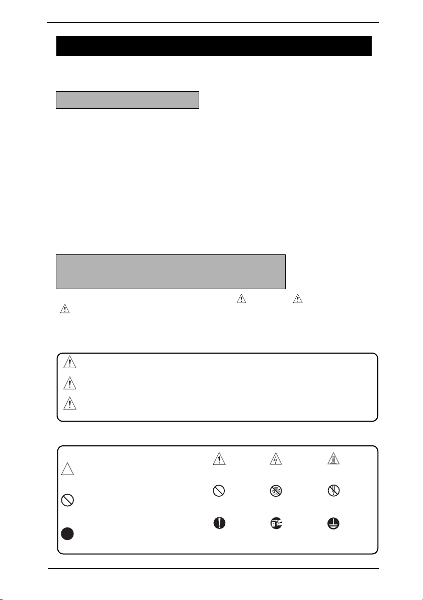
DESCRIPTION ITEMS FOR DANGER, WARNING AND CAUTION
In this service manual, each of three expressions “ DANGER”, “ WARNING”, and
“ CAUTION” is defined as follows together with a symbol mark to be used in a limited
meaning.
When servicing the product, the relevant works (disassembling, reassembling, adjustment,
repair, maintenance, etc.) need to be conducted with utmost care.
DANGER: Action having a high possibility of suffering death or serious injury
WARNING: Action having a possibility of suffering death or serious injury
CAUTION: Action having a possibility of suffering a slight wound, medium
trouble, and property damage
Symbols used for safety and important warning items are defined as follows:
:Precaution when servicing the
product.
:Prohibition when servicing the
product.
:Direction when servicing the
product.
General
precaution
General
prohibition
General
instruction
Electric hazard High temperature
Do not touch
with wet hand
Unplug Ground/Earth
Do not
disassemble
S-1
Page 5
SAFETY AND IMPORTANT WARNING ITEMS
SAFETY WARNINGS
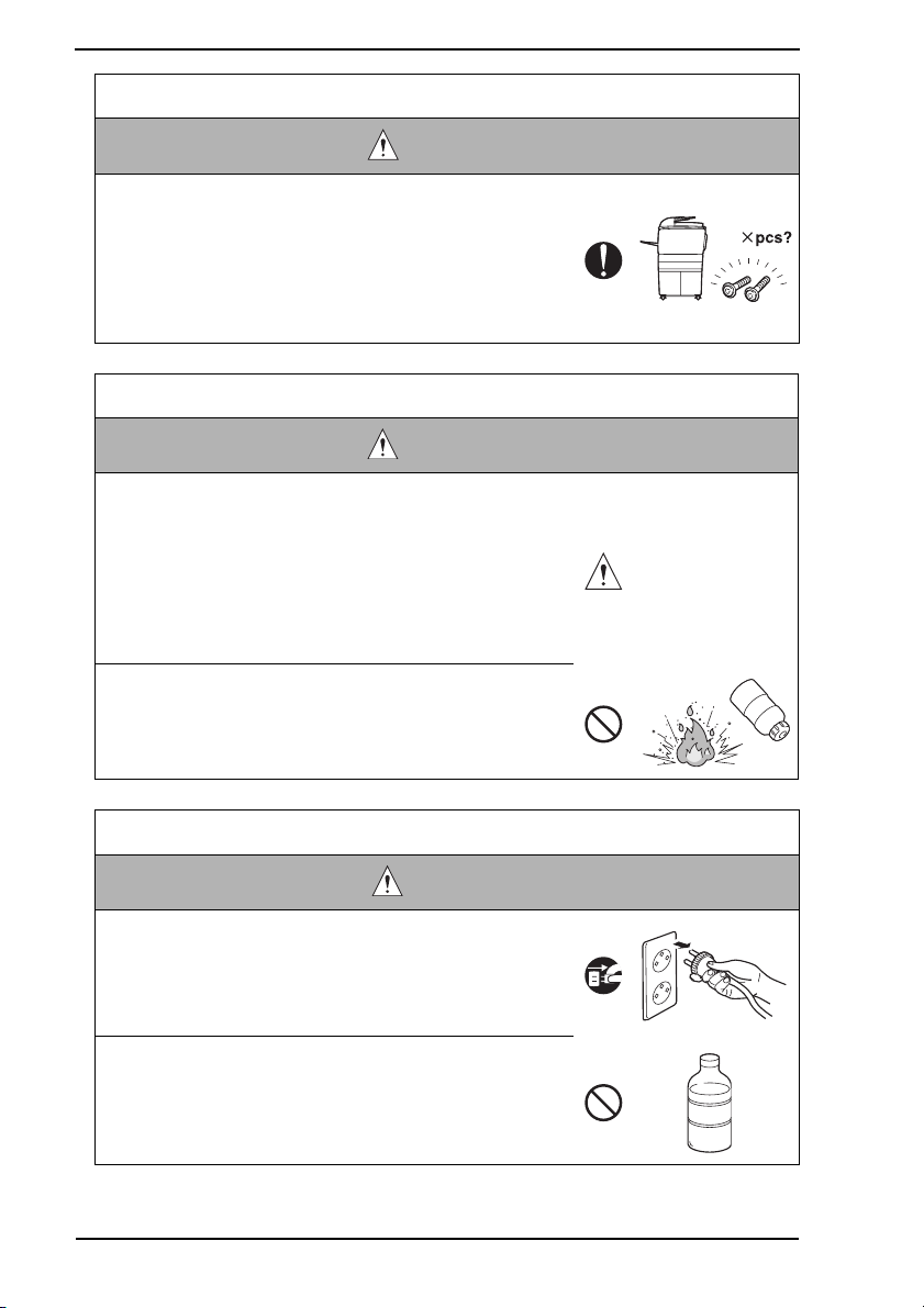
[1] MODIFICATIONS NOT AUTHORIZED BY KONICA MINOLTA
BUSINESS TECHNOLOGIES, INC.
KONICA MINOLTA brand products are renowned for their high reliability. This reliability is
achieved through high-quality design and a solid service network.
Product design is a highly complicated and delicate process where numerous mechanical,
physical, and electrical aspects have to be taken into consideration, with the aim of arriving
at proper tolerances and safety factors. For this reason, unauthorized modifications involve
a high risk of degradation in performance and safety. Such modifications are therefore
strictly prohibited. the points listed below are not exhaustive, but they illustrate the reasoning behind this policy.
Prohibited Actions
DANGER
• Using any cables or power cord not specified by KMBT.
• Using any fuse or thermostat not specified by KMBT.
Safety will not be assured, leading to a risk of fire and
injury.
• Disabling fuse functions or bridging fuse terminals with
wire, metal clips, solder or similar object.
• Disabling relay functions (such as wedging paper between
relay contacts)
• Disabling safety functions (interlocks, safety circuits, etc.)
Safety will not be assured, leading to a risk of fire and
injury.
• Making any modification to the product unless instructed
by KMBT
• Using parts not specified by KMBT
S-2
Page 6

SAFETY AND IMPORTANT WARNING ITEMS
[2] POWER PLUG SELECTION
In some countries or areas, the power plug provided with the product may not fit wall outlet
used in the area. In that case, it is obligation of customer engineer (hereafter called the CE)
to attach appropriate power plug or power cord set in order to connect the product to the
supply.
Power Cord Set or Power Plug
WARNING
• Use power supply cord set which meets the following
criteria:
- provided with a plug having configuration intended for
the connection to wall outlet appropriate for the product's rated voltage and current, and
- the plug has pin/terminal(s) for grounding, and
- provided with three-conductor cable having enough current capacity, and
- the cord set meets regulatory requirements for the area.
Use of inadequate cord set leads to fire or electric shock.
• Attach power plug which meets the following criteria:
- having configuration intended for the connection to wall
outlet appropriate for the product's rated voltage and
current, and
- the plug has pin/terminal(s) for grounding, and
- meets regulatory requirements for the area.
Use of inadequate cord set leads to the product connecting to inadequate power supply (voltage, current capacity,
grounding), and may result in fire or electric shock.
• Conductors in the power cable must be connected to terminals of the plug according to the following order:
• Black or Brown: L (line)
• White or Light Blue: N (neutral)
• Green/Yellow: PE (earth)
Wrong connection may cancel safeguards within the
product, and results in fire or electric shock.
kw
S-3
Page 7
SAFETY AND IMPORTANT WARNING ITEMS
[3] CHECKPOINTS WHEN PERFORMING ON-SITE SERVICE
KONICA MINOLTA brand products are extensively tested before shipping, to ensure that all
applicable safety standards are met, in order to protect the customer and customer engineer (hereafter called the CE) from the risk of injury. However, in daily use, any electrical
equipment may be subject to parts wear and eventual failure. In order to maintain safety
and reliability, the CE must perform regular safety checks.
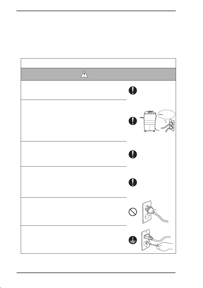
1. Power Supply
Connection to Power Supply
WARNING
• Check that mains voltage is as specified.
Connection to wrong voltage supply may result in fire or
electric shock.
• Connect power plug directly into wall outlet having same
configuration as the plug.
Use of an adapter leads to the product connecting to
inadequate power supply (voltage, current capacity,
grounding), and may result in fire or electric shock.
If proper wall outlet is not available, advice the customer
to contact qualified electrician for the installation.
• Plug the power cord into the dedicated wall outlet with a
capacity greater than the maximum power consumption.
If excessive current flows in the wall outlet, fire may
result.
• If two or more power cords can be plugged into the wall
outlet, the total load must not exceed the rating of the wall
outlet.
If excessive current flows in the wall outlet, fire may
result.
• Make sure the power cord is plugged in the wall outlet
securely.
Contact problems may lead to increased resistance,
overheating, and the risk of fire.
kw
• Check whether the product is grounded properly.
If current leakage occurs in an ungrounded product, you
may suffer electric shock while operating the product.
Connect power plug to grounded wall outlet.
S-4
Page 8
SAFETY AND IMPORTANT WARNING ITEMS
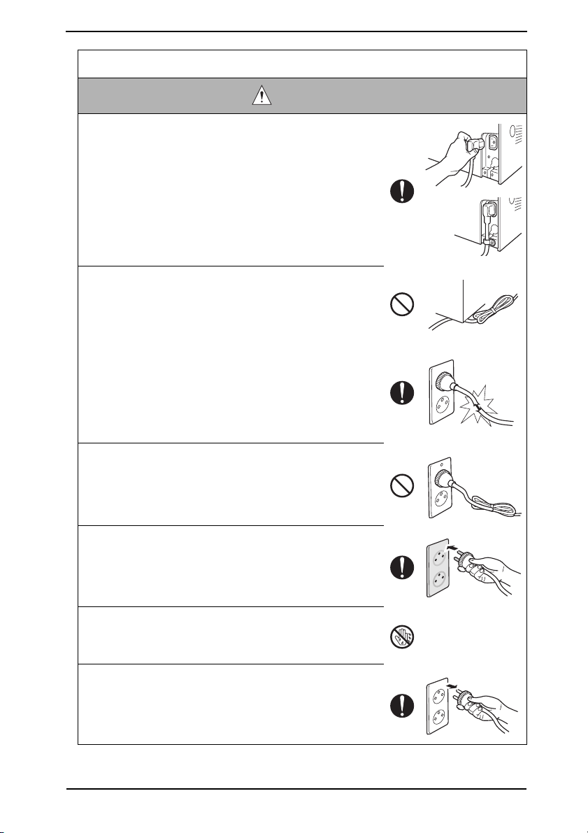
Power Plug and Cord
WARNING
• When using the power cord set (inlet type) that came with
this product, make sure the connector is securely inserted
in the inlet of the product.
When securing measure is provided, secure the cord with
the fixture properly.
If the power cord (inlet type) is not connected to the product securely, a contact problem may lead to increased
resistance, overheating, and risk of fire.
• Check whether the power cord is not stepped on or
pinched by a table and so on.
Overheating may occur there, leading to a risk of fire.
• Check whether the power cord is damaged. Check
whether the sheath is damaged.
If the power plug, cord, or sheath is damaged, replace
with a new power cord (with plug and connector on each
end) specified by KMBT. Using the damaged power cord
may result in fire or electric shock.
• Do not bundle or tie the power cord.
Overheating may occur there, leading to a risk of fire.
• Check whether dust is collected around the power plug
and wall outlet.
Using the power plug and wall outlet without removing
dust may result in fire.
• Do not insert the power plug into the wall outlet with a wet
hand.
The risk of electric shock exists.
• When unplugging the power cord, grasp the plug, not the
cable.
The cable may be broken, leading to a risk of fire and
electric shock.
S-5
Page 9
SAFETY AND IMPORTANT WARNING ITEMS
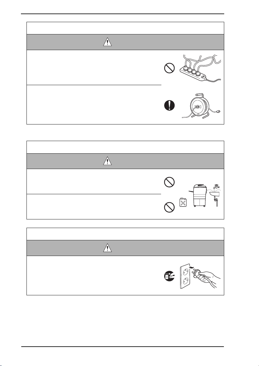
Wiring
WARNING
• Never use multi-plug adapters to plug multiple power cords
in the same outlet.
If used, the risk of fire exists.
• When an extension cord is required, use a specified one.
Current that can flow in the extension cord is limited, so
using a too long extension cord may result in fire.
Do not use an extension cable reel with the cable taken
up. Fire may result.
2. Installation Requirements
Prohibited Installation Places
WARNING
• Do not place the product near flammable materials or volatile materials that may catch fire.
A risk of fire exists.
• Do not place the product in a place exposed to water such
as rain.
A risk of fire and electric shock exists.
When not Using the Product for a long time
WARNING
• When the product is not used over an extended period of
time (holidays, etc.), switch it off and unplug the power
cord.
Dust collected around the power plug and outlet may
cause fire.
S-6
Page 10
SAFETY AND IMPORTANT WARNING ITEMS
Ventilation
CAUTION
• The product generates ozone gas during operation, but it
will not be harmful to the human body.
If a bad smell of ozone is present in the following cases,
ventilate the room.
a. When the product is used in a poorly ventilated room
b. When taking a lot of copies
c. When using multiple products at the same time
Stability
CAUTION
• Be sure to lock the caster stoppers.
In the case of an earthquake and so on, the product may
slide, leading to a injury.
Inspection before Servicing
CAUTION
• Before conducting an inspection, read all relevant documentation (service manual, technical notices, etc.) and
proceed with the inspection following the prescribed procedure in safety clothes, using only the prescribed tools.
Do not make any adjustment not described in the documentation.
If the prescribed procedure or tool is not used, the product may break and a risk of injury or fire exists.
• Before conducting an inspection, be sure to disconnect
the power plugs from the product and options.
When the power plug is inserted in the wall outlet, some
units are still powered even if the POWER switch is
turned OFF. A risk of electric shock exists.
• The area around the fixing unit is hot.
You may get burnt.
S-7
Page 11
SAFETY AND IMPORTANT WARNING ITEMS
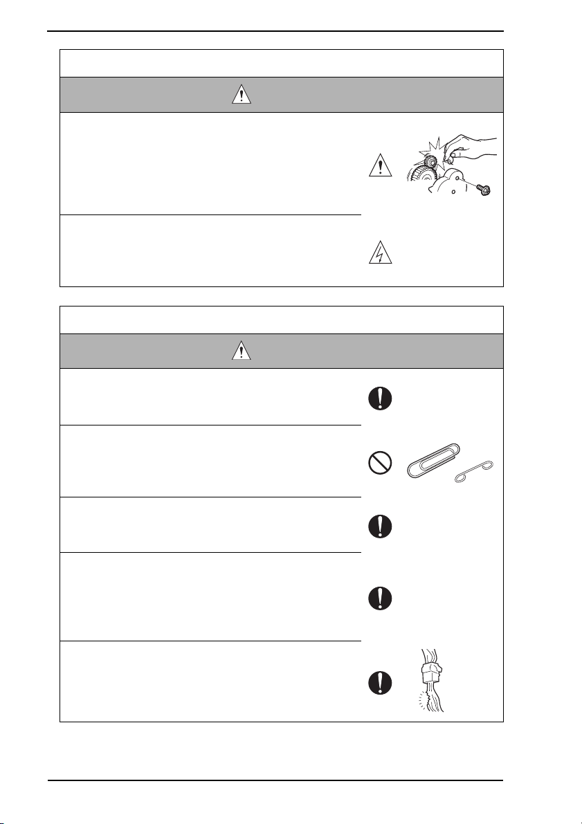
Work Performed with the Product Powered On
WARNING
• Take every care when making adjustments or performing
an operation check with the product powered.
If you make adjustments or perform an operation check
with the external cover detached, you may touch live or
high-voltage parts or you may be caught in moving gears
or the timing belt, leading to a risk of injury.
• Take every care when servicing with the external cover
detached.
High-voltage exists around the drum unit. A risk of electric shock exists.
Safety Checkpoints
WARNING
• Check the exterior and frame for edges, burrs, and other
damage.
The user or CE may be injured.
• Do not allow any metal parts such as clips, staples, and
screws to fall into the product.
They can short internal circuits and cause electric shock
or fire.
• Check wiring for squeezing and any other damage.
Current can leak, leading to a risk of electric shock or
fire.
• Carefully remove all toner remnants and dust from electrical parts and electrode units such as a charging corona
unit.
Current can leak, leading to a risk of product trouble or
fire.
• Check high-voltage cables and sheaths for any damage.
Current can leak, leading to a risk of electric shock or
fire.
S-8
Page 12
SAFETY AND IMPORTANT WARNING ITEMS
Safety Checkpoints
WARNING
• Check electrode units such as a charging corona unit for
deterioration and sign of leakage.
Current can leak, leading to a risk of trouble or fire.
• Before disassembling or adjusting the write unit (P/H unit)
incorporating a laser, make sure that the power cord has
been disconnected.
The laser light can enter your eye, leading to a risk of
loss of eyesight.
• Do not remove the cover of the write unit. Do not supply
power with the write unit shifted from the specified mounting position.
The laser light can enter your eye, leading to a risk of
loss of eyesight.
• When replacing a lithium battery, replace it with a new lithium battery specified in the Parts Guide Manual. Dispose
of the used lithium battery using the method specified by
local authority.
Improper replacement can cause explosion.
• After replacing a part to which AC voltage is applied (e.g.,
optical lamp and fixing lamp), be sure to check the installation state.
A risk of fire exists.
• Check the interlock switch and actuator for loosening and
check whether the interlock functions properly.
If the interlock does not function, you may receive an
electric shock or be injured when you insert your hand in
the product (e.g., for clearing paper jam).
• Make sure the wiring cannot come into contact with sharp
edges, burrs, or other pointed parts.
Current can leak, leading to a risk of electric shock or
fire.
S-9
Page 13
SAFETY AND IMPORTANT WARNING ITEMS
Safety Checkpoints
WARNING
• Make sure that all screws, components, wiring, connectors, etc. that were removed for safety check and maintenance have been reinstalled in the original location. (Pay
special attention to forgotten connectors, pinched cables,
forgotten screws, etc.)
A risk of product trouble, electric shock, and fire exists.
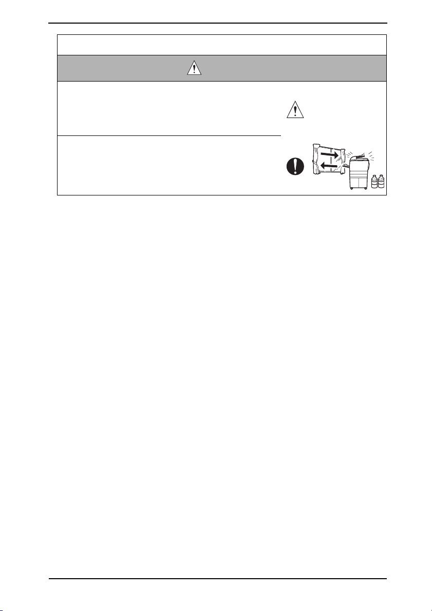
Handling of Consumables
WARNING
• Toner and developer are not harmful substances, but care
must be taken not to breathe excessive amounts or let the
substances come into contact with eyes, etc. It may be
stimulative.
If the substances get in the eye, rinse with plenty of water
immediately. When symptoms are noticeable, consult a
physician.
• Never throw the used cartridge and toner into fire.
You may be burned due to dust explosion.
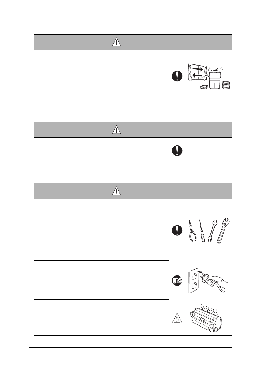
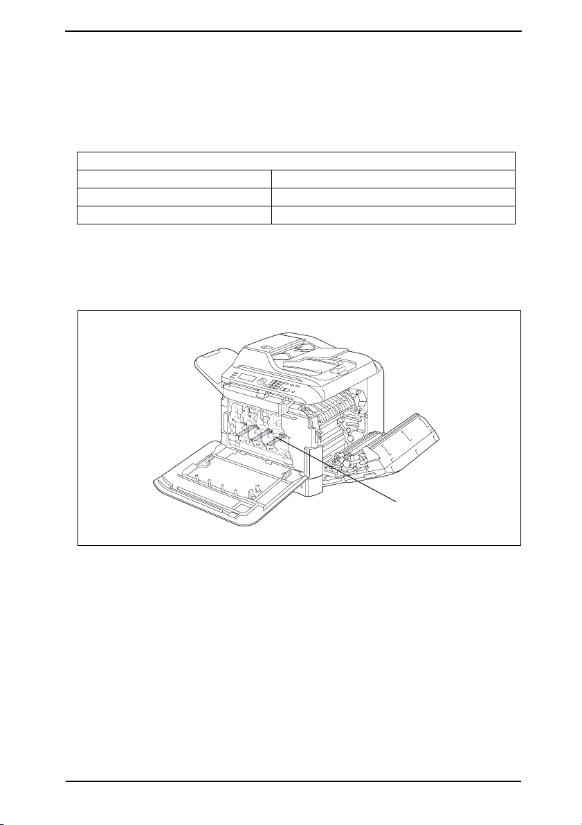
Handling of Service Materials
CAUTION
• Unplug the power cord from the wall outlet.
Drum cleaner (isopropyl alcohol) and roller cleaner (acetone-based) are highly flammable and must be handled
with care. A risk of fire exists.
• Do not replace the cover or turn the product ON before
any solvent remnants on the cleaned parts have fully
evaporated.
A risk of fire exists.
S-10
Page 14
SAFETY AND IMPORTANT WARNING ITEMS
Handling of Service Materials
CAUTION
• Use only a small amount of cleaner at a time and take
care not to spill any liquid. If this happens, immediately
wipe it off.
A risk of fire exists.
• When using any solvent, ventilate the room well.
Breathing large quantities of organic solvents can lead to
discomfort.
S-11
Page 15

SAFETY AND IMPORTANT WARNING ITEMS
[4] Used Batteries Precautions
ALL Areas
CAUTION
Danger of explosion if battery is incorrectly replaced.
Replace only with the same or equivalent type recommended by the manufacturer.
Dispose of used batteries according to the manufacturer’s instructions.
Germany
VORSICHT!
Explosionsgefahr bei unsachgemäßem Austausch der Batterie.
Ersatz nur durch denselben oder einen vom Hersteller empfohlenen gleichwertigen Typ.
Entsorgung gebrauchter Batterien nach Angaben des Herstellers.
France
AT TE N T IO N
Il y a danger d’explosion s’il y a remplacement incorrect de la batterie.
Remplacer uniquement avec une batterie du même type ou d’un type équivalent recommandé par le constructeur.
Mettre au rebut les batteries usagées conformément aux instructions du fabricant.
Denmark
Lithiumbatteri - Eksplosionsfare ved fejlagtig håndtering.
Udskiftning må kun ske med batteri af samme fabrikat og type.
Levér det brugte batteri tilbage til leverandøren.
Finland, Sweden
Paristo voi räjähtää, jos se on virheellisesti asennettu.
Vaihda paristo ainoastaan laitevalmistajan suosittelemaan tyyppiin.
Hävitä käytetty paristo valmistajan ohjeiden mukaisesti.
ADVARSEL!
VAROlTUS
VARNING
Explosionsfara vid felaktigt batteribyte.
Använd samma batterityp eller en ekvivalent typ som rekommenderas av apparattillverkaren.
Kassera använt batteri enligt fabrikantens instruktion.
Norway
Eksplosjonsfare ved feilaktig skifte av batteri.
Benytt samme batteritype eller en tilsvarende type anbefalt av apparatfabrikanten.
Brukte batterier kasseres i henhold til fabrikantens instruksjoner.
ADVARSEL
S-12
Page 16
SAFETY AND IMPORTANT WARNING ITEMS
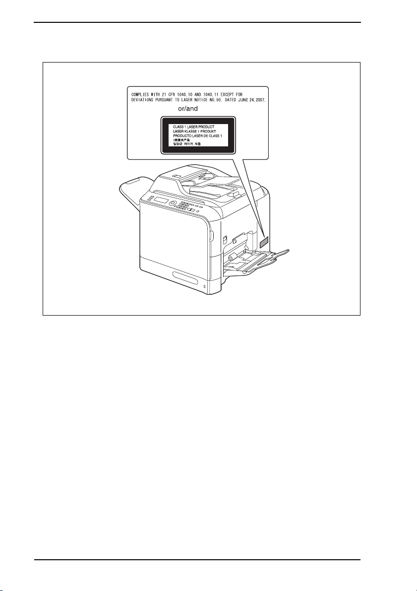
[5] Laser Safety
• This is a digital machine certified as a Class 1 laser product. There is no possibility of
danger from a laser, provided the machine is serviced according to the instruction in this
manual.
5.1 Internal Laser Radiation
semiconductor laser
Maximum power of the laser diode 15 mW
Maximum average radiation power (*) 8.5 µW
Wavelength 770-800 nm
*at laser aperture of the Print Head Unit
• This product employs a Class 3B laser diode that emits an invisible laser beam. The
laser diode and the scanning polygon mirror are incorporated in the print head unit.
• The print head unit is NOT A FIELD SERVICEABLE ITEM. Therefore, the print head unit
should not be opened under any circumstances.
Laser Aperture of
the Print Head Unit
A0FDP0C502DA
S-13
Page 17

SAFETY AND IMPORTANT WARNING ITEMS
U.S.A., Canada
(CDRH Regulation)
• This machine is certified as a Class 1 Laser product under Radiation Performance Standard according to the Food, Drug and Cosmetic Act of 1990. Compliance is mandatory
for Laser products marketed in the United States and is reported to the Center for
Devices and Radiological Health (CDRH) of the U.S. Food and Drug Administration of
the U.S. Department of Health and Human Services (DHHS). This means that the device
does not produce hazardous laser radiation.
• The label shown on page S-16 indicates compliance with the CDRH regulations and
must be attached to laser products marketed in the United States.
.
CAUTION
• Use of controls, adjustments or performance of procedures other than those
specified in this manual may result in hazardous radiation exposure.
semiconductor laser
Maximum power of the laser diode 15 mW
Wavelength 770-800 nm
All Areas
CAUTION
• Use of controls, adjustments or performance of procedures other than those
specified in this manual may result in hazardous radiation exposure.
semiconductor laser
Maximum power of the laser diode 15 mW
Wavelength 770-800 nm
Denmark
ADVARSEL
• Usynlig laserstråling ved åbning, når sikkerhedsafbrydere er ude af funktion.
Undgå udsættelse for stråling. Klasse 1 laser produkt der opfylder IEC60825-1
sikkerheds kravene.
halvlederlaser
Laserdiodens højeste styrke 15 mW
bølgelængden 770-800 nm
S-14
Page 18

SAFETY AND IMPORTANT WARNING ITEMS
Finland, Sweden
LUOKAN 1 LASERLAITE
KLASS 1 LASER APPARAT
VAR OITU S!
• Laitteen käyttäminen muulla kuin tässä käyttöohjeessa mainitulla tavalla saattaa altistaa käyttäjän turvallisuusluokan 1 ylittävälle näkymättömälle lasersäteilylle.
puolijohdelaser
Laserdiodin suurin teho 15 mW
aallonpituus 770-800 nm
VARNING!
• Om apparaten används på annat sätt än i denna bruksanvisning specificerats,
kan användaren utsättas för osynlig laserstrålning, som överskrider gränsen för
laserklass 1.
halvledarlaser
Den maximala effekten för laserdioden 15 mW
våglängden 770-800 nm
VAR O!
• Avattaessa ja suojalukitus ohitettaessa olet alttiina näkymättomälle lasersäteilylle. Älä katso säteeseen.
VARNING!
• Osynlig laserstråining när denna del är öppnad och spärren är urkopplad.
Betrakta ej stråien.
Norway
ADVERSEL
• Dersom apparatet brukes på annen måte enn spesifisert i denne bruksanvisning, kan brukeren utsettes för unsynlig laserstrålning, som overskrider grensen
for laser klass 1.
halvleder laser
Maksimal effekt till laserdiode 15 mW
bølgelengde 770-800 nm
S-15
Page 19
SAFETY AND IMPORTANT WARNING ITEMS
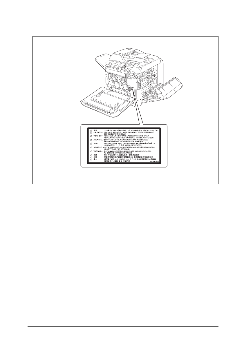
5.2 Laser Safety Label
• A laser safety label is attached to the inside of the machine as shown below.
S-16
A0FDP0E500DA
Page 20
SAFETY AND IMPORTANT WARNING ITEMS
5.3 Laser Caution Label
• A laser caution label is attached to the outside of the machine as shown below.
A0FDP0E501DA
S-17
Page 21

SAFETY AND IMPORTANT WARNING ITEMS
5.4 PRECAUTIONS FOR HANDLING THE LASER EQUIPMENT
• When laser protective goggles are to be used, select ones with a lens conforming to the
above specifications.
• When a disassembly job needs to be performed in the laser beam path, such as when
working around the printerhead and PC Drum, be sure first to turn the printer OFF.
• If the job requires that the printer be left ON, take off your watch and ring and wear laser
protective goggles.
• A highly reflective tool can be dangerous if it is brought into the laser beam path. Use
utmost care when handling tools on the user’s premises.
• The Print Head is not to be disassembled or adjusted in the field. Replace the Unit or
Assembly including the Control Board. Therefore, remove the Laser Diode, and do not
perform Control Board trimmer adjustment.
S-18
Page 22
SAFETY AND IMPORTANT WARNING ITEMS
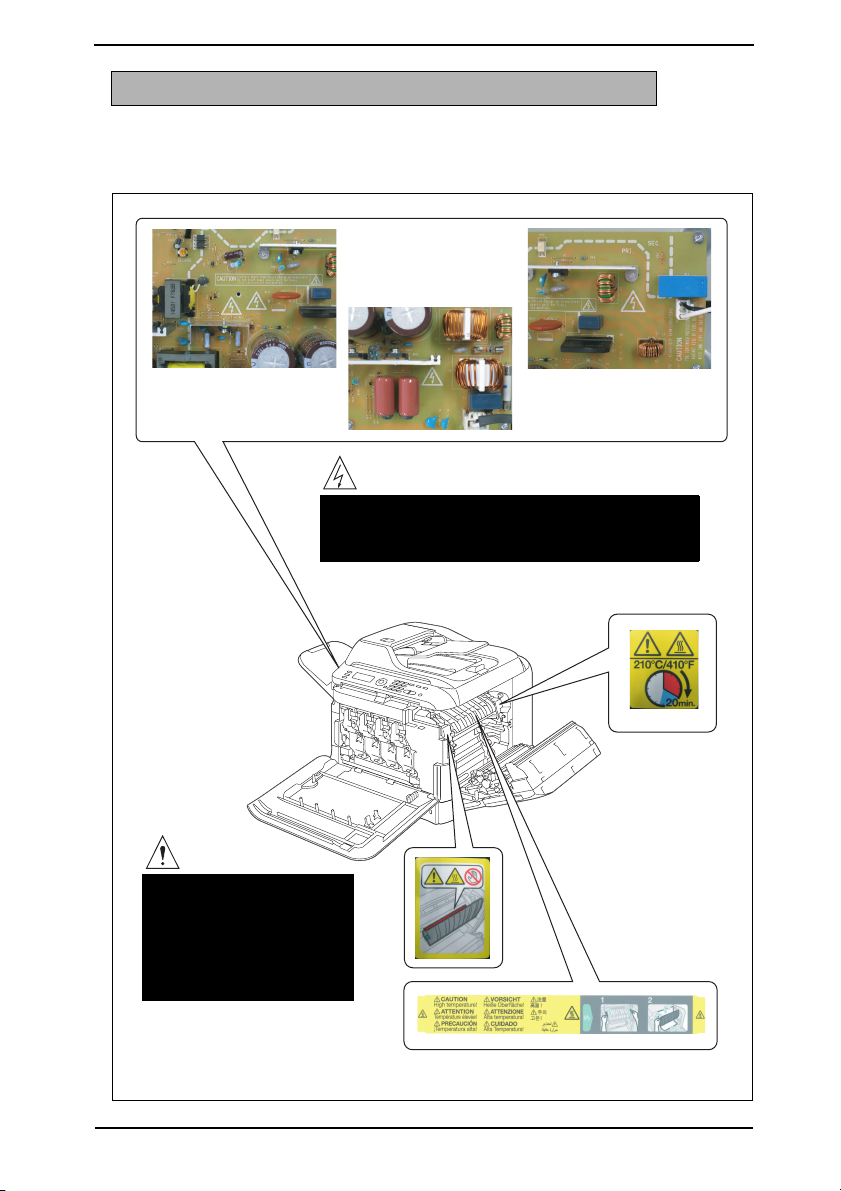
WARNING INDICATIONS ON THE MACHINE
Caution labels shown are attached in some areas on/in the machine.
When accessing these areas for maintenance, repair, or adjustment, special care should
be taken to avoid burns and electric shock.
High voltage
• This area generates high voltage.
Be careful not to touch here when the power is
turned ON to avoid getting an electric shock.
CAUTION
• The area around the
Fuser Unit is extremely
hot.
Touching any part other
than those indicated
may result in burns.
A0FDP0C503DA
S-19
Page 23
SAFETY AND IMPORTANT WARNING ITEMS
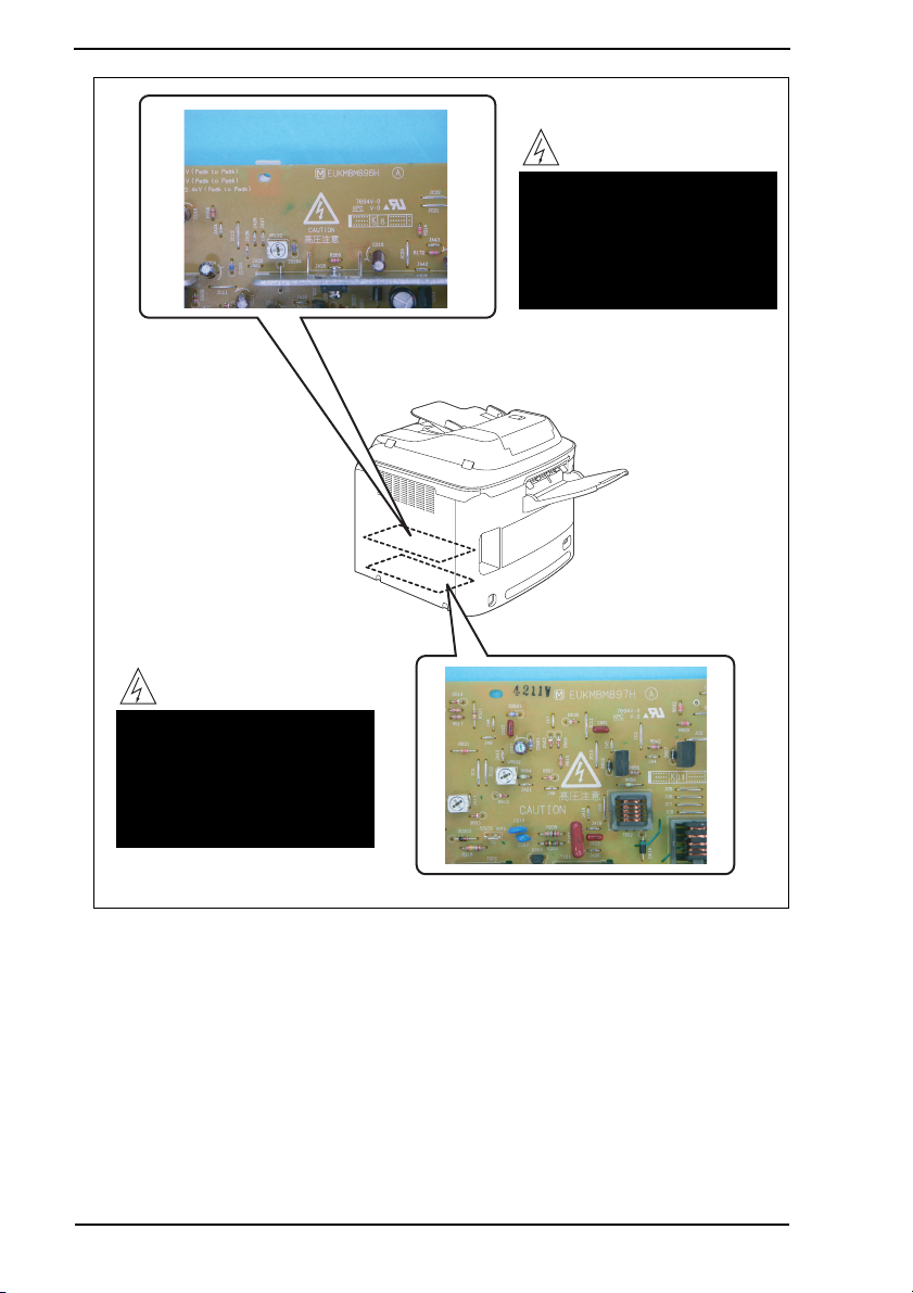
High voltage
• This area generates high
voltage.
Be careful not to touch here
when the power is turned
ON to avoid getting an electric shock.
High voltage
• This area generates high
voltage.
Be careful not to touch here
when the power is turned
ON to avoid getting an electric shock.
S-20
A0FDP0C504DA
Page 24
SAFETY AND IMPORTANT WARNING ITEMS
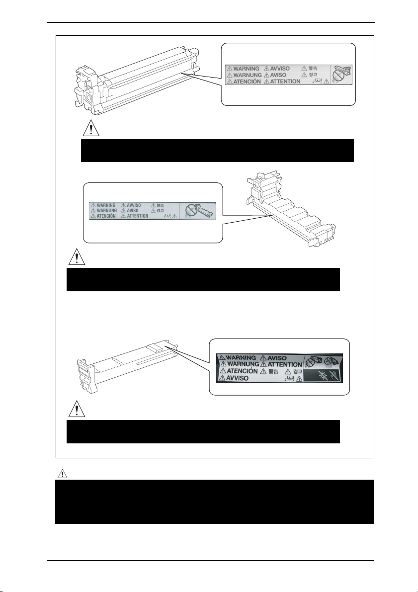
P
U
S
H
Y
WARNING
• Do not burn used Print Units.
Toner expelled from the fire is dangerous.
WARNING
• Do not burn used Waste Toner Bottle.
Toner expelled from the fire is dangerous.
Y
WARNING
• Do not burn used Toner Cartridge.
Toner expelled from the fire is dangerous.
A00FP0C504DA
CAUTION:
• You may be burned or injured if you touch any area that you are advised by any
caution label to keep yourself away from. Do not remove caution labels. And also,
when the caution label is peeled off or soiled and cannot be seen clearly, replace
it with a new caution label.
S-21
Page 25

MEASURES TO TAKE IN CASE OF AN ACCIDENT
MEASURES TO TAKE IN CASE OF AN
ACCIDENT
1. If an accident has occurred, the distributor who has been notified first must immediately
take emergency measures to provide relief to affected persons and to prevent further
damage.
2. If a report of a serious accident has been received from a customer, an on-site evaluation must be carried out quickly and KMBT must be notified.
3. To determine the cause of the accident, conditions and materials must be recorded
through direct on-site checks, in accordance with instructions issued by KMBT.
4. For reports and measures concerning serious accidents, follow the regulations specified by every distributor.
S-22
Page 26

Composition of the service manual
This service manual consists of Theory of Operation section and Field Service section to
explain the main machine and its corresponding options.
Theory of Operation section gives, as information for the CE to get a full understanding of
the product, a rough outline of the object and role of each function, the relationship
between the electrical system and the mechanical system, and the timing of operation of
each part.
Field Service section gives, as information required by the CE at the site (or at the customer’s premise), a rough outline of the service schedule and its details, maintenance
steps, the object and role of each adjustment, error codes and supplementary information.
The basic configuration of each section is as follows. However some options may not be
applied to the following configuration.
<Theory of Operation section>
OUTLINE: Explanation of system configuration,
product specifications, unit configuration, and paper path
COMPOSITION/OPERATION: Explanation of configuration of each unit,
operating system, and control system
<Field service section>
OUTLINE: Explanation of system configuration, and product
specifications
MAINTENANCE: Explanation of service schedule, maintenance steps, ser-
vice tools, removal/reinstallation methods of major parts,
and firmware version up method etc.
ADJUSTMENT/SETTING: Explanation of utility mode, service mode, and mechanical
adjustment etc.
TROUBLESHOOTING: Explanation of lists of jam codes and error codes, and
their countermeasures etc.
APPENDIX: Parts layout drawings, connector layout drawings, timing
chart, overall layout drawing are attached.
C-1
Page 27

Notation of the service manual
A. Product name
In this manual, each of the products is described as follows:
bizhub C20 Main body
(1)
(2) Microsoft Windows NT 4.0: Windows NT 4.0 or Windows NT
Microsoft Windows 2000: Windows 2000
Microsoft Windows XP: Windows XP
Microsoft Windows Vista: Windows Vista
When the description is made in combination of the OS’s mentioned above:
Windows NT 4.0/2000
Windows NT/2000/XP/Vista
B. Brand name
The company names and product names mentioned in this manual are the brand name or
the registered trademark of each company.
C. Feeding direction
• When the long side of the paper is parallel with the feeding direction, it is called short
edge feeding. The feeding direction which is perpendicular to the short edge feeding is
called the long edge feeding.
• Short edge feeding will be identified with [S (abbreviation for Short edge feeding)] on the
paper size. No specific notation is added for the long edge feeding.
When the size has only the short edge feeding with no long edge feeding, [S] will not be
added to the paper size.
<Sample notation>
Paper size Feeding direction Notation
A4
A3 Short edge feeding A3
Long edge feeding A4
Short edge feeding A4S
C-2
Page 28

SERVICE MANUAL
FIELD SERVICE
Main body
2008.09
Ver. 1.0
Page 29

Revision history
After publication of this service manual, the parts and mechanism may be subject to change for
improvement of their performance.
Therefore, the descriptions given in this service manual may not coincide with the actual machine.
When any change has been made to the descriptions in the service manual, a revised version will be
issued with a revision mark added as required.
Revision mark:
• To indicate clearly a section revised, is shown at the left margin of the revised section.
The number inside represents the number of times the revision has been made.
1
1
• To indicate clearly a page that contains the revision, is shown near the page number of the
corresponding page.
The number inside represents the number of times the revision has been made.
NOTE
Revision marks shown in a page are restricted only to the latest ones with the old ones deleted.
• When a page revised in Ver. 2.0 has been changed in Ver. 3.0:
The revision marks for Ver. 3.0 only are shown with those for Ver. 2.0 deleted.
• When a page revised in Ver. 2.0 has not been changed in Ver. 3.0:
The revision marks for Ver. 2.0 are left as they are.
1
1
2008/09 1.0 — Issue of the first edition
Date Service manual Ver. Revision mark Descriptions of revision
Page 30

Field Service Ver. 1.0 Sep. 2008
CONTENTS
bizhub C20 Main body
Outline
1. System configuration............................................................................................... 1
2. Product specifications ............................................................................................. 2
2.1 Fax specifications ................................................................................................. 4
Maintenance
3. Periodical check ...................................................................................................... 5
3.1 Maintenance items................................................................................................ 5
3.1.1 Parts to be replaced by users (CRU) ............................................................ 5
3.1.2 Parts to be replaced by a service engineer (FRU) ........................................ 6
3.2 Maintenance parts ................................................................................................ 6
3.2.1 Replacement parts ........................................................................................ 6
3.3 Concept of parts life.............................................................................................. 7
3.4 Maintenance Procedure (periodical check parts) .................................................8
3.4.1 Replacing the tray 2 feed roller ..................................................................... 8
3.4.2 Replacing the tray 1 feed roller ..................................................................... 9
3.4.3 Replacing the ozone filter............................................................................ 12
3.4.4 Replacing the toner cartridge (C/M/Y/K)..................................................... 13
3.4.5 Replacing the imaging unit (C,M,Y,K) ......................................................... 16
3.4.6 Replacing the waste toner bottle................................................................. 20
3.4.7 Replacing the transfer roller ........................................................................ 21
3.4.8 Replacing the transfer belt .......................................................................... 23
3.4.9 Replacing the fuser unit .............................................................................. 26
4. Service tool ........................................................................................................... 28
4.1 Service material list ............................................................................................ 28
4.2 CE tool list........................................................................................................... 28
5. Remote Setup Utility ............................................................................................. 29
5.1 About RSU.......................................................................................................... 29
5.2 Outline ................................................................................................................ 29
5.2.1 Corresponding OS ...................................................................................... 29
5.2.2 PC environments......................................................................................... 29
5.3 Connection methods........................................................................................... 29
5.3.1 Remote connection (Phone line connection) .............................................. 29
5.3.2 Local connection (USB connection) ............................................................ 30
bizhub C20Outline
MaintenanceAdjustment / Setting
Troubleshooting
Appendix
i
Page 31

5.4 Setup.................................................................................................................. 30
5.4.1 Setup of PC ................................................................................................ 30
5.4.2 Connection and access of user machine.................................................... 30
bizhub C20
5.5 Operation............................................................................................................ 32
5.5.1 Job list......................................................................................................... 32
5.5.2 New (Dial setting) ....................................................................................... 32
5.5.3 Open File .................................................................................................... 35
5.5.4 Update Firmware ........................................................................................ 36
5.5.5 Clear Memory Data .................................................................................... 37
Outline
5.5.6 Clear SRAM Data ....................................................................................... 38
5.6 Function setting.................................................................................................. 39
5.7 Troubleshooting .................................................................................................. 41
5.7.1 Error message list....................................................................................... 41
6. Firmware upgrade................................................................................................. 42
6.1 Controller firmware upgrading ............................................................................ 42
6.1.1 Preparations for firmware upgrading........................................................... 42
MaintenanceAdjustment / Setting
6.1.2 Upgrading procedure .................................................................................. 42
6.2 Firmware upgrading procedure by updater ........................................................ 44
6.2.1 Updating method ........................................................................................ 44
7. Other ..................................................................................................................... 57
7.1 Disassembly/adjustment prohibited items .......................................................... 57
7.2 Disassembly/assembly/cleaning list (other parts) .............................................. 58
7.2.1 Disassembly/assembly parts list ................................................................. 58
7.2.2 Cleaning parts list....................................................................................... 59
7.3 Disassembly/assembly procedure...................................................................... 60
7.3.1 Front cover.................................................................................................. 60
7.3.2 Right front cover.......................................................................................... 60
7.3.3 Operation panel .......................................................................................... 61
7.3.4 Left cover .................................................................................................... 61
7.3.5 Rear cover .................................................................................................. 62
Troubleshooting
7.3.6 Right rear cover .......................................................................................... 62
7.3.7 Tray 2 .......................................................................................................... 63
7.3.8 MFP board/2 (MFPB/2)............................................................................... 63
7.3.9 NCU board (NCUB) .................................................................................... 64
7.3.10 MFP board/1 (MFPB/1)............................................................................... 65
Appendix
7.3.11 Print control board (PRCB) ......................................................................... 66
7.3.12 DC power supply (DCPU)........................................................................... 68
7.3.13 High voltage unit/1 (HV1)............................................................................ 71
Field Service Ver. 1.0 Sep. 2008
ii
Page 32

Field Service Ver. 1.0 Sep. 2008
7.3.14 High voltage unit/2 (HV2)............................................................................ 72
7.3.15 Relay board (REYB).................................................................................... 73
7.3.16 Toner level sensor board (TLSB) ................................................................ 75
7.3.17 PH unit ........................................................................................................ 78
7.3.18 Driving unit .................................................................................................. 85
7.3.19 Scanner unit................................................................................................ 86
7.3.20 Exposure unit .............................................................................................. 87
7.3.21 Backup Battery............................................................................................ 89
7.3.22 PWB box ..................................................................................................... 90
7.3.23 PWB box lower cover .................................................................................. 94
7.3.24 Color PC drum motor (M2).......................................................................... 94
7.3.25 Transport motor (M3) .................................................................................. 95
7.3.26 Fusing motor (M4)....................................................................................... 95
7.3.27 K Developing motor (M5) ............................................................................ 95
7.3.28 Toner supply motor/Y, M (M6) ..................................................................... 96
7.3.29 Toner supply motor/C, K (M7) ..................................................................... 96
7.3.30 Scanner motor (M100) ................................................................................ 97
7.3.31 Media feed clutch assy................................................................................ 99
7.3.32 Registration roller clutch (CL3).................................................................. 100
7.3.33 1st image transfer pressure/retraction clutch (CL4).................................. 101
7.3.34 2nd image transfer pressure/retraction clutch (CL5)................................. 102
7.3.35 Switchback roller feed clutch (CL11)......................................................... 103
7.3.36 Switchback roller reverse clutch (CL12).................................................... 105
7.3.37 Duplex transport roller clutch (CL13) ........................................................ 106
7.3.38 Temperature/ humidity sensor (TEM/HUMS) ............................................ 108
7.3.39 IDC sensor board/Re, IDC sensor board/Fr (IDCSB/R, IDCSB/L)............ 109
7.3.40 Speaker (SP1)........................................................................................... 110
7.3.41 Memory (DIMM) ........................................................................................ 110
7.3.42 Hard disk................................................................................................... 111
7.4 Cleaning procedure .......................................................................................... 112
7.4.1 Tray 1 feed roller........................................................................................ 112
7.4.2 Tray 2 feed roller........................................................................................ 112
7.4.3 Vertical transport roller .............................................................................. 113
7.4.4 Laser irradiation section ............................................................................ 113
bizhub C20Outline
MaintenanceAdjustment / Setting
Troubleshooting
Adjustment/Setting
8. How to use the adjustment section ..................................................................... 115
9. Description of the control panel........................................................................... 116
Appendix
iii
Page 33

9.1 Control panel display........................................................................................ 116
9.1.1 Main screen .............................................................................................. 116
9.1.2 Print screen............................................................................................... 116
bizhub C20
9.1.3 Toner supply screen.................................................................................. 117
10. REPORT/STATUS mode..................................................................................... 118
10.1 REPORT/STATUS mode function tree ............................................................. 118
10.2 TOTAL PRINT................................................................................................... 119
10.2.1 TOTAL PRINT ........................................................................................... 119
10.2.2 MONO COPY ........................................................................................... 119
Outline
10.2.3 COLOR COPY.......................................................................................... 119
10.2.4 MONO PRINT........................................................................................... 119
10.2.5 COLOR PRINT ......................................................................................... 119
10.2.6 FAX PRINT ............................................................................................... 119
10.2.7 TOTAL SCAN............................................................................................ 119
10.3 SUPPLY STATUS ............................................................................................. 120
10.3.1 C TONER.................................................................................................. 120
MaintenanceAdjustment / Setting
10.3.2 M TONER ................................................................................................. 120
10.3.3 Y TONER.................................................................................................. 120
10.3.4 K TONER.................................................................................................. 120
10.3.5 C I-UNIT.................................................................................................... 120
10.3.6 M I-UNIT ................................................................................................... 120
10.3.7 Y I-UNIT.................................................................................................... 120
10.3.8 K I-UNIT.................................................................................................... 120
10.4 TX/RX RESULT ................................................................................................ 121
10.5 REPORT........................................................................................................... 121
10.5.1 TX RESULT REPORT............................................................................... 121
10.5.2 RX RESULT REPORT .............................................................................. 121
10.5.3 ACTIVITY REPORT.................................................................................. 121
10.5.4 MEMORY DATA LIST................................................................................ 121
Troubleshooting
10.5.5 MEMORY IMAGE PRINT ......................................................................... 121
10.5.6 FAVORITE LIST........................................................................................ 121
10.5.7 SPEED DIAL LIST .................................................................................... 122
10.5.8 GROUP DIAL LIST ................................................................................... 122
10.5.9 UTILITY MAP............................................................................................ 122
10.5.10 PS/PCL MENU MAP................................................................................. 122
Appendix
10.5.11 CONFIGURATION PAGE.......................................................................... 122
10.5.12 PS FONT LIST.......................................................................................... 126
10.5.13 PCL FONT LIST ....................................................................................... 126
Field Service Ver. 1.0 Sep. 2008
iv
Page 34

Field Service Ver. 1.0 Sep. 2008
10.5.14 DIRECTORY LIST..................................................................................... 126
11. UTILITY mode..................................................................................................... 127
11.1 UTILITY mode function tree.............................................................................. 127
11.2 MACHINE SETTING......................................................................................... 131
11.2.1 AUTO PANEL RESET ............................................................................... 131
11.2.2 PREHEAT MODE...................................................................................... 131
11.2.3 ENERGY SAVE MODE............................................................................. 131
11.2.4 LCD CONTRAST ...................................................................................... 131
11.2.5 KEY SPEED.............................................................................................. 131
11.2.6 LANGUAGE .............................................................................................. 132
11.2.7 LAMP OFF TIME ...................................................................................... 132
11.2.8 LAMP WARMUP TIME ............................................................................. 132
11.2.9 BUZZER VOLUME.................................................................................... 132
11.2.10 INITIAL MODE .......................................................................................... 133
11.2.11 TONER EMPTY ........................................................................................133
11.2.12 TONER NEAR EMPTY .............................................................................133
11.2.13 I-UNIT NEAR EMPTY ............................................................................... 133
11.2.14 AUTO CONTINUE..................................................................................... 133
11.2.15 CALIBRATION .......................................................................................... 134
11.3 PAPER SETUP................................................................................................. 135
11.3.1 TRAY1 PAPER .......................................................................................... 135
11.3.2 TRAY2 PAPER .......................................................................................... 135
11.4 ADMIN. MANAGEMENT .................................................................................. 136
11.4.1 ADMINISTRATOR NO............................................................................... 136
11.4.2 REMOTE MONITOR................................................................................. 136
11.4.3 NETWORK SETTING ............................................................................... 136
11.4.4 E-MAIL SETTING ..................................................................................... 142
11.4.5 LDAP SETTING ........................................................................................ 145
11.4.6 CAMERA DIRECT .................................................................................... 147
11.4.7 USB SETTING .......................................................................................... 148
11.4.8 COMM. SETTING ..................................................................................... 148
11.4.9 USER SETTING ....................................................................................... 149
11.4.10 AUTO REDIAL .......................................................................................... 150
11.4.11 SUPPLIES REPLACE............................................................................... 150
11.5 COPY SETTING............................................................................................... 151
11.5.1 PAPER PRIORITY .................................................................................... 151
11.5.2 QUALITY PRIORITY................................................................................. 151
11.5.3 DENSITY PRIORITY ................................................................................ 151
bizhub C20Outline
MaintenanceAdjustment / Setting
Troubleshooting
Appendix
v
Page 35

11.5.4 DENSITY LEVEL ...................................................................................... 151
11.5.5 OUTPUT PRIORITY ................................................................................. 152
11.5.6 4IN1 COPY ORDER ................................................................................. 152
bizhub C20
11.5.7 DUPLEX COPY ........................................................................................ 152
11.6 DIAL REGISTER .............................................................................................. 153
11.6.1 FAVORITE ................................................................................................ 153
11.6.2 SPEED DIAL............................................................................................. 153
11.6.3 GROUP DIAL............................................................................................ 153
11.7 FAX TX OPERATION ....................................................................................... 153
Outline
11.7.1 DENSITY LEVEL ...................................................................................... 153
11.7.2 QUALITY PRIORITY................................................................................. 154
11.7.3 DEFULT TX............................................................................................... 154
11.7.4 HEADER................................................................................................... 154
11.8 FAX RX OPERATION ....................................................................................... 155
11.8.1 MEMORY RX MODE................................................................................ 155
11.8.2 NO. of RINGS ........................................................................................... 155
MaintenanceAdjustment / Setting
11.8.3 REDUCTION RX ...................................................................................... 155
11.8.4 RX PRINT ................................................................................................. 160
11.8.5 RX MODE ................................................................................................. 160
11.8.6 FORWARD ............................................................................................... 161
11.8.7 FOOTER................................................................................................... 161
11.8.8 SELECT TRAY.......................................................................................... 162
11.9 REPORTING .................................................................................................... 162
11.9.1 ACTIVITY REPORT.................................................................................. 162
11.9.2 TX RESULT REPORT............................................................................... 162
11.9.3 RX RESULT REPORT .............................................................................. 162
11.10 SCAN SETTING ............................................................................................... 163
11.10.1 RESOLUTION .......................................................................................... 163
11.10.2 IMAGE FORMAT....................................................................................... 163
Troubleshooting
11.10.3 CODING METHOD ................................................................................... 163
11.10.4 FILE SIZE ................................................................................................. 163
11.10.5 QUALITY PRIORITY................................................................................. 163
11.10.6 DENSITY LEVEL ...................................................................................... 164
11.11 DIRECT PRINT ................................................................................................ 164
11.11.1 IMAGE QUALITY...................................................................................... 164
Appendix
11.11.2 PAPER SIZE ............................................................................................. 164
11.11.3 N-UP LAYOUT .......................................................................................... 164
12. PS/PCL PRINT mode ......................................................................................... 165
Field Service Ver. 1.0 Sep. 2008
vi
Page 36

Field Service Ver. 1.0 Sep. 2008
12.1 PS/PCL PRINT mode function tree .................................................................. 165
12.2 PROOF/PRINT MENU...................................................................................... 167
12.3 PAPER MENU .................................................................................................. 167
12.3.1 ANY TRAY SETTING................................................................................ 167
12.3.2 TRAY CHAINING ...................................................................................... 168
12.3.3 TRAY MAPPING ....................................................................................... 168
12.3.4 DUPLEX.................................................................................................... 169
12.3.5 COPIES .................................................................................................... 169
12.3.6 COLLATE .................................................................................................. 169
12.4 QUALITY MENU............................................................................................... 170
12.4.1 COLOR MODE ......................................................................................... 170
12.4.2 BRIGHTNESS........................................................................................... 170
12.4.3 HALFTONE............................................................................................... 170
12.4.4 EDGE ENHANCEMENT ........................................................................... 171
12.4.5 EDGE STRENGTH ................................................................................... 171
12.4.6 ECONOMY PRINT.................................................................................... 172
12.4.7 PCL SETTING .......................................................................................... 172
12.4.8 PS SETTING............................................................................................. 174
12.4.9 CALIBRATION .......................................................................................... 178
12.5 SYS DEFAULT MENU ...................................................................................... 179
12.5.1 EMULATION ............................................................................................. 179
12.5.2 PAPER ...................................................................................................... 181
12.5.3 GRAYSCALE PAGE.................................................................................. 182
12.5.4 STARTUP OPTIONS................................................................................. 182
12.5.5 HOLD JOB TIMEOUT............................................................................... 183
12.5.6 HDD FORMAT .......................................................................................... 183
12.5.7 CARD FORMAT ........................................................................................ 183
13. User service mode .............................................................................................. 184
13.1 User service mode function tree ....................................................................... 184
13.2 FAX MAINTENANCE ........................................................................................ 187
13.3 ADJUST............................................................................................................ 187
13.3.1 TOP ADJUSTMENT.................................................................................. 187
13.3.2 LEFT ADJ. (FRONT)................................................................................. 187
13.3.3 LEFT ADJ. (BACK) ................................................................................... 187
13.3.4 TRANSFER POWER ................................................................................ 187
13.4 AIDC MODE ..................................................................................................... 187
13.5 CRU USAGE..................................................................................................... 187
13.5.1 TRANSFER BELT ..................................................................................... 187
bizhub C20Outline
MaintenanceAdjustment / Setting
Troubleshooting
Appendix
vii
Page 37

13.5.2 FUSER UNIT ............................................................................................ 187
13.5.3 TRANSFER ROLLER ............................................................................... 187
13.6 SUPPLIES REPLACE ...................................................................................... 187
bizhub C20
13.7 MAINTENANCE MENU.................................................................................... 188
13.7.1 PRINT MENU ........................................................................................... 188
13.7.2 IMG ADJ THICK ....................................................................................... 189
13.7.3 IMG ADJ BLACK....................................................................................... 189
14. SERVICE MODE................................................................................................. 190
14.1 SERVICE MODE entry procedure.................................................................... 190
Outline
14.2 SERVICE MODE function tree ......................................................................... 190
14.3 SERVICE’S CHOICE........................................................................................ 195
14.3.1 TX SPEED ................................................................................................ 195
14.3.2 RX SPEED................................................................................................ 195
14.3.3 TX LEVEL ................................................................................................. 195
14.3.4 RX LEVEL................................................................................................. 195
14.3.5 DTMF LEVEL............................................................................................ 195
MaintenanceAdjustment / Setting
14.3.6 CNG LEVEL.............................................................................................. 196
14.3.7 CED LEVEL .............................................................................................. 196
14.3.8 ECM MODE .............................................................................................. 196
14.3.9 CODING SCHEME ................................................................................... 196
14.3.10 TONER EMPTY REPORT ........................................................................ 197
14.3.11 PROTOCOL REPORT .............................................................................. 197
14.3.12 TWAIN TIMEOUT ..................................................................................... 197
14.3.13 ENERGY SAVE MODE ............................................................................ 198
14.3.14 ENABLE WARNING ................................................................................. 198
14.4 ADJUST ........................................................................................................... 198
14.4.1 CCD MAIN ZOOM .................................................................................... 199
14.4.2 CCD SUB ZOOM...................................................................................... 200
14.4.3 CCD MAIN REGIST.................................................................................. 201
Troubleshooting
14.4.4 CCD SUB REGIST ................................................................................... 202
14.4.5 ADF 1ST SUB ZOOM............................................................................... 203
14.4.6 ADF 1ST MAIN REG ................................................................................ 203
14.4.7 ADF 1ST SUB REG.................................................................................. 204
14.4.8 ADF 2ND SUB ZOOM .............................................................................. 204
14.4.9 ADF 2ND MAIN REG................................................................................ 204
Appendix
14.4.10 ADF 2ND SUB REG ................................................................................. 205
14.4.11 ADF LOOP................................................................................................ 205
14.4.12 FLICKER................................................................................................... 205
Field Service Ver. 1.0 Sep. 2008
viii
Page 38

Field Service Ver. 1.0 Sep. 2008
14.4.13 TOP ADJUSTMENT.................................................................................. 206
14.4.14 LEFT ADJ. (FRONT)................................................................................. 206
14.4.15 LEFT ADJ. (BACK) ................................................................................... 206
14.4.16 TRANSFER POWER ................................................................................207
14.4.17 IMG ADJ THICK........................................................................................ 208
14.4.18 IMG ADJ BLACK....................................................................................... 208
14.4.19 IMAGE ADJ PARAM ................................................................................. 208
14.4.20 MAXIMUM DENSITY ................................................................................209
14.4.21 FUSER SPEED......................................................................................... 209
14.4.22 TEMPERATURE ....................................................................................... 210
14.4.23 AIDC MODE.............................................................................................. 210
14.4.24 SUPPLIES REPLACE............................................................................... 210
14.4.25 BK CLEAR ................................................................................................ 211
14.5 COUNTER........................................................................................................ 211
14.5.1 TOTAL PRINT ........................................................................................... 211
14.5.2 FAX COUNTER......................................................................................... 212
14.5.3 SCAN COUNTER ..................................................................................... 212
14.5.4 TRAY COUNTER ...................................................................................... 212
14.5.5 PAPER SIZE COUNTER .......................................................................... 212
14.5.6 PAPER TYPE COUNTER ......................................................................... 213
14.5.7 APPLICATION COUNT. ............................................................................ 213
14.5.8 SUPPLIES STATUS .................................................................................. 213
14.5.9 CRU USAGE............................................................................................. 213
14.5.10 JAM COUNTER ........................................................................................214
14.5.11 TROUBLE COUNTER .............................................................................. 214
14.6 DISPLAY........................................................................................................... 214
14.6.1 MAIN F/W VER. ........................................................................................ 214
14.6.2 ENGINE F/W VER. ................................................................................... 214
14.6.3 MAIN RAM SIZE ....................................................................................... 214
14.6.4 SERIAL NO............................................................................................... 214
14.6.5 PP F/W VER. ............................................................................................ 214
14.6.6 PP BOOT VER.......................................................................................... 214
14.6.7 PRINTER RAM SIZE ................................................................................ 215
14.6.8 HARD DISK .............................................................................................. 215
14.6.9 CARD........................................................................................................ 215
14.7 FUNCTION ....................................................................................................... 216
14.7.1 PAPER FEED TEST ................................................................................. 216
14.7.2 PRN TEST PATTERN ............................................................................... 216
bizhub C20Outline
MaintenanceAdjustment / Setting
Troubleshooting
Appendix
ix
Page 39

14.7.3 ADF FEED TEST...................................................................................... 217
14.7.4 COPY ADF GLASS .................................................................................. 217
14.7.5 FAX RES. COPY TEST ............................................................................ 217
bizhub C20
14.7.6 SCAN TEST.............................................................................................. 217
14.7.7 PRINTER TEST........................................................................................ 218
14.7.8 ADF TEST ................................................................................................ 220
14.8 SOFT SWITCH................................................................................................. 221
14.8.1 KEY DEFINITION FOR SOFT SWITCH................................................... 221
14.9 REPORT........................................................................................................... 221
Outline
14.9.1 SERVICE DATA LIST ................................................................................ 221
14.9.2 ERROR CODE LIST................................................................................. 224
14.9.3 T.30 PROTOCOL LIST.............................................................................. 225
14.10 ADMIN. REGISTRATION ................................................................................. 227
14.11 FIXED ZOOM CHANGE................................................................................... 227
14.12 FACTORY TEST............................................................................................... 227
14.13 CLEAR DATA.................................................................................................... 228
MaintenanceAdjustment / Setting
14.13.1 SRAM CLEAR .......................................................................................... 228
14.13.2 MEMORY CLEAR..................................................................................... 228
14.14 PS/PCL............................................................................................................. 229
14.14.1 PRINT MENU ........................................................................................... 229
14.14.2 SOFT SWITCH ......................................................................................... 236
15. SOFT SWITCH set ............................................................................................. 237
15.1 Description ....................................................................................................... 237
15.2 Default setting................................................................................................... 237
15.2.1 Country for each marketing area .............................................................. 237
15.2.2 Soft switch list ........................................................................................... 238
15.2.3 Default soft switch setting for each market area....................................... 242
15.3 Soft switch definition......................................................................................... 264
15.3.1 SOFT SWITCH: #01 ................................................................................. 264
15.3.2 SOFT SWITCH: #02 ................................................................................. 265
Troubleshooting
15.3.3 SOFT SWITCH: #03 ................................................................................. 266
15.3.4 SOFT SWITCH: #04 ................................................................................. 267
15.3.5 SOFT SWITCH: #05 ................................................................................. 268
15.3.6 SOFT SWITCH: #06 ................................................................................. 269
15.3.7 SOFT SWITCH: #07 ................................................................................. 269
Appendix
15.3.8 SOFT SWITCH: #08 ................................................................................. 270
15.3.9 SOFT SWITCH: #09 ................................................................................. 270
15.3.10 SOFT SWITCH: #10 ................................................................................. 271
Field Service Ver. 1.0 Sep. 2008
x
Page 40

Field Service Ver. 1.0 Sep. 2008
15.3.11 SOFT SWITCH: #11 ................................................................................. 272
15.3.12 SOFT SWITCH: #12 ................................................................................. 273
15.3.13 SOFT SWITCH: #13 ................................................................................. 274
15.3.14 SOFT SWITCH: #14 ................................................................................. 274
15.3.15 SOFT SWITCH: #15 ................................................................................. 275
15.3.16 SOFT SWITCH: #16 ................................................................................. 275
15.3.17 SOFT SWITCH: #17 ................................................................................. 276
15.3.18 SOFT SWITCH: #18 ................................................................................. 277
15.3.19 SOFT SWITCH: #19 ................................................................................. 278
15.3.20 SOFT SWITCH: #20 ................................................................................. 278
15.3.21 SOFT SWITCH: #21 ................................................................................. 279
15.3.22 SOFT SWITCH: #22 ................................................................................. 280
15.3.23 SOFT SWITCH: #23 ................................................................................. 280
15.3.24 SOFT SWITCH: #24 (Part 1) .................................................................... 281
15.3.25 SOFT SWITCH: #24 (Part 2) .................................................................... 282
15.3.26 SOFT SWITCH: #24 (Part 3) .................................................................... 283
15.3.27 SOFT SWITCH: #25 ................................................................................. 283
15.3.28 SOFT SWITCH: #26 ................................................................................. 284
15.3.29 SOFT SWITCH: #27 ................................................................................. 284
15.3.30 SOFT SWITCH: #28 ................................................................................. 285
15.3.31 SOFT SWITCH: #29 ................................................................................. 286
15.3.32 SOFT SWITCH: #30 ................................................................................. 287
15.3.33 SOFT SWITCH: #31 ................................................................................. 288
15.3.34 SOFT SWITCH: #32 ................................................................................. 288
15.3.35 SOFT SWITCH: #33 ................................................................................. 289
15.3.36 SOFT SWITCH: #34 ................................................................................. 289
15.3.37 SOFT SWITCH: #35 ................................................................................. 290
15.3.38 SOFT SWITCH: #36 ................................................................................. 291
15.3.39 SOFT SWITCH: #37 ................................................................................. 292
15.3.40 SOFT SWITCH: #38 ................................................................................. 292
15.3.41 SOFT SWITCH: #39 ................................................................................. 293
15.3.42 SOFT SWITCH: #40 ................................................................................. 294
15.3.43 SOFT SWITCH: #41 ................................................................................. 295
15.3.44 SOFT SWITCH: #42 ................................................................................. 296
15.3.45 SOFT SWITCH: #43 ................................................................................. 296
15.3.46 SOFT SWITCH: #44 ................................................................................. 296
15.3.47 SOFT SWITCH: #45 ................................................................................. 297
bizhub C20Outline
MaintenanceAdjustment / Setting
Troubleshooting
Appendix
xi
Page 41

15.3.48 SOFT SWITCH: #46 ................................................................................. 297
15.3.49 SOFT SWITCH: #47 ................................................................................. 298
15.3.50 SOFT SWITCH: #48 ................................................................................. 298
bizhub C20
Outline
MaintenanceAdjustment / Setting
15.3.51 SOFT SWITCH: #49 ................................................................................. 299
15.3.52 SOFT SWITCH: #50 ................................................................................. 299
15.3.53 SOFT SWITCH: #51 ................................................................................. 300
15.3.54 SOFT SWITCH: #52 ................................................................................. 300
15.3.55 SOFT SWITCH: #53 ................................................................................. 301
15.3.56 SOFT SWITCH: #54 ................................................................................. 301
15.3.57 SOFT SWITCH: #55 ................................................................................. 302
15.3.58 SOFT SWITCH: #56 ................................................................................. 302
15.3.59 SOFT SWITCH: #57 ................................................................................. 302
15.3.60 SOFT SWITCH: #58 ................................................................................. 303
15.3.61 SOFT SWITCH: #59 (Part 1) .................................................................... 304
15.3.62 SOFT SWITCH: #59 (Part 2) .................................................................... 305
15.3.63 SOFT SWITCH: #59 (Part 3) .................................................................... 306
15.3.64 SOFT SWITCH: #60 ................................................................................. 307
15.3.65 SOFT SWITCH: #61 ................................................................................. 307
15.3.66 SOFT SWITCH: #62 ................................................................................. 308
15.3.67 SOFT SWITCH: #63 ................................................................................. 308
15.3.68 SOFT SWITCH: #64 ................................................................................. 309
16. Fax Protocols ...................................................................................................... 310
16.1 G3 ECM (G3 Error Correction Mode)............................................................... 310
16.2 Line control....................................................................................................... 311
16.2.1 Procedure of G3 mode communication .................................................... 311
16.3 Table of reference code.................................................................................... 312
16.4 How to analyze the T30 protocol monitor ......................................................... 313
Field Service Ver. 1.0 Sep. 2008
Troubleshooting
Troubleshooting
Appendix
17. Jam display ......................................................................................................... 321
17.1 Misfeed display................................................................................................. 321
17.2 Sensor layout.................................................................................................... 322
17.3 Solution ............................................................................................................ 323
xii
17.1.1 Misfeed display resetting procedure ......................................................... 321
17.3.1 Initial check items ..................................................................................... 323
17.3.2 Misfeed at tray 2 paper feed section ......................................................... 323
17.3.3 Misfeed at fusing section .......................................................................... 324
17.3.4 Misfeed at transfer section........................................................................ 325
Page 42

Field Service Ver. 1.0 Sep. 2008
17.3.5 Misfeed at duplex paper feed section........................................................ 326
17.3.6 Misfeed at duplex paper transport section ................................................ 327
17.3.7 Misfeed at tray1 paper feed section .......................................................... 328
17.3.8 Misfeed at horizontal transport section ..................................................... 328
17.3.9 Misfeed at exit section............................................................................... 329
17.3.10 Misfeed at switch back section.................................................................. 329
18. Malfunction code ................................................................................................. 330
18.1 Trouble codes (service call) ..............................................................................330
18.1.1 Trouble code list ........................................................................................ 330
18.2 Resetting a malfunction .................................................................................... 334
18.3 Solution............................................................................................................. 335
18.3.1 0010: Color PC drum motor malfunction................................................... 335
18.3.2 0017: Transport motor malfunction ........................................................... 335
18.3.3 0018: K developing motor malfunction...................................................... 336
18.3.4 001B: Color developing motor malfunction ............................................... 336
18.3.5 0045: Defogger fan motor malfunction...................................................... 337
18.3.6 0046: Fusing fan motor malfunction.......................................................... 337
18.3.7 004A: Duplex cooling fan motor malfunction............................................. 337
18.3.8 004C: Ozone ventilation fan motor malfunction ........................................ 338
18.3.9 004E: DC power supply fan motor malfunction......................................... 338
18.3.10 0060: Fusing motor malfunction................................................................ 339
18.3.11 0094: 2nd image transfer pressure/retraction failure................................. 339
18.3.12 0096: 1st image transfer pressure/retraction failure.................................. 340
18.3.13 0300: Polygon motor malfunction.............................................................. 340
18.3.14 0310: Laser malfunction............................................................................ 341
18.3.15 0500: Heating roller warm-up failure ......................................................... 341
18.3.16 0502: Thermistor open-circuit failure ........................................................ 341
18.3.17 0503: Thermistor resistance failure........................................................... 341
18.3.18 0510: Abnormally low heating roller temperature ..................................... 341
18.3.19 0520: Abnormally high heating roller temperature ....................................341
18.3.20 0F50: OHP sensor malfunction ................................................................. 341
18.3.21 0F52: Toner level sensor /Y malfunction ................................................... 342
18.3.22 0F53: Toner level sensor /M malfunction .................................................. 342
18.3.23 0F54: Toner level sensor /C malfunction................................................... 342
8.3.24 0F55: Toner level sensor /K malfunction ................................................... 342
1
18.3.25 13C0: Print control board malfunction....................................................... 342
18.3.26 13DD: Backup data error .......................................................................... 342
18.3.27 13F0: Engine control failure ......................................................................343
bizhub C20Outline
MaintenanceAdjustment / Setting
Troubleshooting
Appendix
xiii
Page 43

18.3.28 13E2: Engine flash ROM write error ......................................................... 343
18.3.29 13E3: Engine flash ROM device fault ....................................................... 343
18.3.30 SCANNER MOTION ERROR CHECK SCANNER LOCK ........................ 343
bizhub C20
18.3.31 14A3: IR lamp malfunction........................................................................ 344
18.3.32 1038: Engine connect error ...................................................................... 344
18.3.33 3FFF: Flash ROM write error .................................................................... 345
18.3.34 4FFF: Controller connect error ................................................................. 345
18.3.35 C002: RAM error at startup (standard memory)
Outline
18.3.36 C013: MAC address error at startup
18.3.37 C025: Controller ROM error (Configuration information error)
18.3.38 C050: HDD access error........................................................................... 347
18.3.39 C051: HDD full error ................................................................................. 348
MaintenanceAdjustment / Setting
18.3.40 C052: Compact flash access error ........................................................... 348
18.3.41 C053: Compact flash full error .................................................................. 349
18.3.42 C060: Firmware update error.................................................................... 349
18.3.43 FFFF: Interface communication error ....................................................... 350
19. Power supply troubles......................................................................................... 351
19.1 Machine is not energized at all (DCPU operation check) ................................. 351
19.2 Control panel indicators do not light ................................................................. 351
19.3 Fusing heaters do not operate ......................................................................... 352
20. Image quality problems....................................................................................... 353
20.1 Printer system .................................................................................................. 353
20.1.1 White lines/bands, colored lines/bands in sub scan direction................... 353
20.1.2 White lines/bands, colored lines/bands in main scan direction................. 354
20.1.3 Uneven density in sub scan direction ....................................................... 355
20.1.4 Uneven density in main scan direction ..................................................... 356
Troubleshooting
20.1.5 Low image density .................................................................................... 357
20.1.6 Gradation reproduction failure .................................................................. 358
20.1.7 Foggy background .................................................................................... 359
20.1.8 Poor color reproduction............................................................................. 360
20.1.9 Void areas, white spots ............................................................................. 361
Appendix
20.1.10 Colored spots............................................................................................ 362
20.1.11 Blurred image ........................................................................................... 363
20.1.12 Blank copy, black copy.............................................................................. 364
Field Service Ver. 1.0 Sep. 2008
C003: RAM error at startup (expanded memory) ..................................... 346
C015: BOOT ROM error at startup
C022: NVRAM error at startup ................................................................. 346
C026: Controller ROM error (Access error)
C027: Controller ROM error (Data error) .................................................. 347
xiv
Page 44

Field Service Ver. 1.0 Sep. 2008
20.1.13 Incorrect color image registration.............................................................. 365
20.1.14 Poor fusing performance, offset ................................................................ 366
20.1.15 Brush effect ............................................................................................... 367
20.1.16 Back marking ............................................................................................ 368
20.1.17 Uneven pitch ............................................................................................. 369
21. FAX error ............................................................................................................. 370
21.1 Communication error ........................................................................................ 370
21.2 Outline .............................................................................................................. 370
21.3 Error occurring during transmission.................................................................. 371
21.3.1 Error occurring during reception ............................................................... 371
21.4 Error code ......................................................................................................... 372
21.4.1 Reception.................................................................................................. 372
21.4.2 Transmission ............................................................................................. 374
22. Scan error ........................................................................................................... 377
Appendix
23. Parts layout drawing ............................................................................................ 379
23.1 Main body ......................................................................................................... 379
23.2 Auto Document Feeder Unit ............................................................................. 382
23.3 Lower feeder unit (option)................................................................................. 383
24. Connector layout drawing.................................................................................... 384
bizhub C20Outline
MaintenanceAdjustment / Setting
xv
Troubleshooting
Appendix
Page 45

bizhub C20
Outline
MaintenanceAdjustment / Setting
Field Service Ver. 1.0 Sep. 2008
Blank Page
Troubleshooting
Appendix
xvi
Page 46

Field Service Ver. 1.0 Sep. 2008 1. System configuration
Outline
1. System configuration
Machine front view
[1]
[2]
A0FDF1C500DA
[1] bizhub C20 [2] Lower feeder unit
bizhub C20Outline
1
Page 47

2. Product specifications Field Service Ver. 1.0 Sep. 2008
2. Product specifications
A. Type
Type Desktop tandem full-color A4 laser beam printer
bizhub C20
Outline
Printing system Semiconductor laser and electrostatic image transfer to plain paper
Exposure system 4 laser diode and 1 polygon mirror
PC drum type OPC (organic photo conductor)
Photoconductor
cleaning
Scan resolution 600 x 600 dpi, 600 x 300 dpi
Print resolution 600 x 600 dpi x 4bit
Copy resolution 600 x 600 dpi, 1200 x 600 dpi
Platen Stationary
Registration Rear left edge
Paper feeding system
Developing system Single-element developing system
Charging system Needle charging system (with Ozone suction feature)
Image transfer
system
Paper separating
system
Fusing system Belt fusing
Paper exit system Face down (Output tray capacity: 250 sheets)
Blade cleaning system
Tray1: 100 sheets
Tray2: 250 sheets
Tray3: 500 sheets (Option)
Intermediate transfer belt system
Curvature separation + charge-neutralizing system
B. Functions
Cold start: 58 seconds
Warm-up time
Process speed
First-page-out-time 18.0 second (Full-color mode, A4S/LetterS, 1-sided mode, plain paper)
Print speed
Sleep-mode to ready: 40 seconds
(Power on to ready, at ambient temperature of 23 °C/73.4 °F and rated source
voltage)
144 mm/sec (plain paper, Monochrome/full color mode)
72 mm/sec (thick paper/OHP, Monochrome/full color mode)
24 pages/min. (A4S, 1-sided print, plain paper)
25 pages/min. (LetterS, 1-sided print, plain paper)
12 pages/min. (A4S, 1-sided print, thick paper)
12.5 pages/min. (LetterS, 1-sided print, thick paper)
2
Page 48

Field Service Ver. 1.0 Sep. 2008 2. Product specifications
C. Media
Paper source (maximum tray capacity)
Tray 1 Tray 2
100 sheets 250 sheets
20 sheets
92 to 216 mm
(3.6 to 8.5 inch)
148 to 356 mm
(5.8 to 14.0 inch)
92 to 216 mm
(3.6 to 8.5 inch)
148 to 297 mm
(5.8 to 11.7 inch)
⎯
Media type
Media
dimensions
Ty pe
Plain paper
(60 to 90 g/m
Thick 1 (91 to 150 g/m
Thick 2 (151 to 210 g/m
2
; 16 to 24 lb)
2
)
2
)
OHP
Label
Letterhead
Transparencies
Glossy 1 (100 to 128 g/m
Glossy 2 (129 to 158 g/m
2
)
2
)
Postcard
Envelope 10 sheets
Width
Length
D. Maintenance
Machine durability 400,000 prints or 5 years, whichever comes first
E. Machine specifications
Power requirements
Max power consumption
Dimensions
Weight
Operating noise
Voltage: AC 100V, 120 V, 220 to 240 V
Frequency: 50 to 60 Hz ± 3 Hz
1,250 W or less
25 W less (Energy saver mode)
539 (W) x 590 (D) x 578 (H) mm
21.23 (W) x 23.23 (D) x 22.75 (H) inch
50.0 kg (110.3 lb) or less without consumables
55.0 kg (121.3 lb) or less with consumables
During standby : 39 dB (A) or less
During printing : 53.5 dB (A) or less
During copying : 54.5 dB (A) or less (with ADF)
bizhub C20Outline
F. Operating environment
Temperature 10 °C to 35 °C / 50 °F to 95 °F (with a fluctuation of 10 °C / 18 °F or less per hour)
Humidity 15% to 85% (with a fluctuation of 20% or less per hour)
3
Page 49

2. Product specifications Field Service Ver. 1.0 Sep. 2008
G. Print functions
Type Built-in type controller
Pentium II: 400 MHz or higher
bizhub C20
Outline
Personal computer
Operating system Microsoft Windows Vista Home Basic/Home Premium/Ultimate/Business/
Standard memory Printer: 256 MB, Copier: 256MB
I/O Interfaces 10Base-T/100Base-TX/1000Base-T Ethernet interface port
PowerPC G3 or later (G4 or later is recommended)
Macintosh equipped with an Intel processor
Enterprise, Windows Vista Home Basic /Home Premium /Ultimate/Business /
Enterprise x64 Edition, Windows XP Home Edition/Professional (Service Pack
2 or later), Windows XP Professional x64 Edition, Windows Server 2003, Windows Server 2003 x64 Edition, Windows 2000 (Service Pack 4 or later)
Mac OS X (10.2.8 or later; We recommend installing the newest patch)
Red Hat Linux 9.0, SuSE Linux 8.2
USB (PictBride1.0, USB Device Printing) RJ-45 connector
NOTE
• These specifications are subject to change without notice.
2.1 Fax specifications
Standard (203 dpi x 98 dpi)
Resolution
Halftone level
Automatic reduction
Compatibility ECM/Super G3
Modem speed V.34 (up to 33.6 Kbps)
Transmit speed 3 second/page (at V.34)
Compression MH/MR/MMR/JBIG
Memory for receiving 6 MB for Fax-RX (approx. 250 pages), (included in 32 MB NAND flash)
Remote setting Available via Tel line and USB
Paper size A4S, LegalS, LetterS
Paper type Plain paper, recycled paper
Functions
Fine (203 dpi x 196 dpi)
Super fine (203 dpi x 392 dpi)
Standard/Fine/Super fine
Halftone standard/Halftone fine/Halftone super fine
Receive Supported
Transmit Supported
Speed dial 220
Group dial 20 groups (50 destination stations for one group)
Broadcast
Other supported
functions
Available maximum 255 stations.
(Speed dial 220 stations, full dial 16 stations)
Timer transmission, address book, real time clock, auto
redial, reduce/split, smoothing
4
Page 50

Field Service Ver. 1.0 Sep. 2008 3. Periodical check
Maintenance
3. Periodical check
3.1 Maintenance items
3.1.1 Parts to be replaced by users (CRU)
No Class Part to be replaced Number of prints Clean Replace Description
1
2
Processing
section
3 Imaging unit (C, M, Y, K)
4 Ozone filter *4 120,000
Tray 2
5
media feed
section
Tray 1
6
media feed
section
7
Image
8 Transfer roller *4
transfer
section
9 Waste toner bottle
Fusing
10
section
Standard in-box toner cartridge (C, M, Y, K)
High-capacity toner
cartridge (C, M, Y, K)
Feed roller
Feed roller
Transfer belt unit
Fuser unit
*1 : 2 pages/job
*2 : When printed in black only
*3 : When printed in color only
*4 : The transfer roller and ozone filter are available as a kit and must be replaced at the
same time
8,000 (Continuous
printing)
8,000 (Continuous
printing)
30,000 (Continuous
printing)
When malfunction
occurs
When malfunction
occurs
120,000 (Continuous
printing, 2P/J *1)
120,000 (Continuous
printing, 2P/J *1)
36,000 (K *2)
9,000 (Y,M,C,K *3)
120,000 (Continuous
printing)
100,000 (2P/J *1)
bizhub C20
Maintenance
5
Page 51

3. Periodical check Field Service Ver. 1.0 Sep. 2008
3.1.2 Parts to be replaced by a service engineer (FRU)
No Class Part to be replaced Number of prints Clean Replace Description
Tray 2
1
bizhub C20
media feed
2
media feed
3
feeder unit
section
Tray 1
section
Lower
Feed roller 300,000
Feed roller 300,000
Feed roller 300,000
3.2 Maintenance parts
• To ensure that the machine produces good prints and to extend its service life, it is recommended that the maintenance jobs described in this schedule be carried out as
instructed.
• The replacing time is to be determined by the total counter value.
• Maintenance conditions are based on A4S or letterS,1-side print.
3.2.1 Replacement parts
A. Main body
Maintenance
No Class Maintenance parts
1 Tray 2 Feed roller 1 300,000 4138 3032 ## P. 8
2 Tray 1 Feed roller 1 300,000 4138 3032 ## P. 9
Quan
tity
Actual
durable cycle
Parts No.
Descrip-
tion
Ref.page
B. Option
No Class Maintenance parts
Lower
1
feeder unit
Feed roller 1 300,000 4128 3214 ## *1
Quan
tity
Actual
durable cycle
*1: For details, see the optional lower feeder unit service manual.
6
Parts No.
Descrip-
tions
Ref.page
Page 52

Field Service Ver. 1.0 Sep. 2008 3. Periodical check
3.3 Concept of parts life
Waste toner
bottle
Fuser unit
Ozone filter ⎯ 120,000 prints
Transfer roller • Based on the number of pages printed, the life is detected. 120,000 prints
Transfer belt
Imaging unit
• Detected by the waste toner full sensor.
• A waste toner full condition is detected when about 1,500
color printed pages are produced after a waste toner near
full condition has been detected.
• Based on the fusing motor rotation data, the fuser unit driving time is counted.
Comparing the fuser unit driving time count value with the
number of pages printed, the machine detects the one that
reaches its life value earlier.
• Base on the intermediate transport motor rotation data, the
transfer belt driving time is counted and the life is detected.
• Base on the color PC drum motor or intermediate transport
motor rotation data, the imaging unit driving time is
counted.
Comparing the imaging unit driving time count value and
the number of pages printed, the machine detects the one
that reaches its life value earlier.
Description Life value
Monochrome:
36,000 prints
Color: 9,000 prints
120,000 prints
(Continuous printing)
100,000 prints (2P/J)
120,000 prints
30,000 prints
(Continuous printing)
20,000 prints (2P/J)
A. Conditions for life specifications values
• The life specification values represent the number of pages printed or figures equivalent
to it when the given conditions (see the table given below) are met. They may be more or
less, depending on the machine operating conditions of each individual user.
Item Description
Job type 2 consecutive pages (2 pages/job)
Media size A4S or LetterS
Color ratio Black to Color = 6 : 4
Original density C/W ratio = 5% each color
bizhub C20
Maintenance
7
Page 53

3. Periodical check Field Service Ver. 1.0 Sep. 2008
3.4 Maintenance Procedure (periodical check parts)
3.4.1 Replacing the tray 2 feed roller A. Periodically replaced parts/cycle
• Tray 2 feed roller: Every 300,000 prints
bizhub C20
B. Procedure
1. Slide out the tray 2.
[2]
[2][3]
2. Lock the media lift plate [1].
3. Remove two C-rings [2], and remove
the bearing [3] at the front.
Maintenance
[1]
[1]
[2]
A0FDF2C001DA
4. Remove the C-ring [1], and remove
the feed roller [2].
A0FDF2C002DA
NOTE
• When reinstalling the feed roller [1],
make sure that it is mounted in the
direction shown in the illustration
on the left.
[1]
A011F2C501DA
8
Page 54

Field Service Ver. 1.0 Sep. 2008 3. Periodical check
3.4.2 Replacing the tray 1 feed roller A. Periodically replaced parts/cycle
• Tray 1 feed roller: Every 300,000 prints
B. Procedure
1. Open the right door.
2. Remove two screws [1].
bizhub C20
[1]
[2]
[1]
[1]
[1]
A0FDF2C003DA
A00FF2C004DA
Maintenance
3. Remove two screws [1], and remove
the cover [2].
4. Remove two screws [1], and remove
two springs [2].
[2]
[2]
[1]
A00FF2C005DA
9
Page 55

3. Periodical check Field Service Ver. 1.0 Sep. 2008
bizhub C20
Maintenance
[1]
[1]
[1]
[2]
[2]
5. Remove the screw [1], and remove
the cover [2].
A00FF2C006DA
6. Pull the hook part [1] in the direction
of the arrow and remove it.
Remove the transport unit [2].
A0FDF2C004DA
7. Remove four screws [1], and remove
the tray 1 feed roller unit [2].
10
[2]
A0FDF2C005DA
Page 56

Field Service Ver. 1.0 Sep. 2008 3. Periodical check
[2]
[1]
[1]
[1]
[2]
[2]
[3]
8. Remove the E-ring [1] and remove
the bearing [2]. Then, slide the tray 1
feed roller assy [3] in the direction of
the arrow shown.
bizhub C20
A00FF2C009DA
NOTE
• When reinstalling the tray 1 feed
roller assy, make sure that the shaft
[2] sits on the front side of the stopper [1] as shown in the illustration.
Maintenance
[2] [3]
[1]
A00FF2C507DA
9. Remove the E-ring [1], and remove
the clutch [2] and the feed roller [3].
A00FF2C010DA
11
Page 57

3. Periodical check Field Service Ver. 1.0 Sep. 2008
NOTE
• When reinstalling the feed roller [1]
and the clutch, make sure that it is
mounted in the direction shown in
bizhub C20
[1]
A011F2C503DA
the illustration on the left.
3.4.3 Replacing the ozone filter A. Periodically replaced parts/cycle
• Ozone filter: Every 120,000 prints
B. Procedure
1. Hold onto the handle of the ozone fil-
ter [1] and slide it out of the machine.
Maintenance
[1]
A0FDF2C500DA
2. Install a new ozone filter in the machine.
3. Replace the transfer roller.
See P.21
12
Page 58

Field Service Ver. 1.0 Sep. 2008 3. Periodical check
3.4.4 Replacing the toner cartridge (C/M/Y/K) A. Periodically replaced parts/cycle
• Toner cartridge furnished with the machine (C, M, Y, K): Every 8,000 prints
• High-capacity toner cartridge (C, M, Y, K): Every 8,000 prints
B. Removal procedure
1. Open the front cover.
2. Slide the lock lever [1] to the right.
[1]
Y
A0FDF2C501DA
3. Pull down the lock lever to unlock the
toner cartridge.
Y
bizhub C20
Maintenance
[1]
[2]
Y
[1]
A0FDF2C502DA
4. Grasp the toner cartridge handle [1]
and pull the toner cartridge [2] out.
Y
Y
A0FDF2C503DA
13
Page 59

3. Periodical check Field Service Ver. 1.0 Sep. 2008
C. Reinstallation procedure
1. Take the toner cartridge out of its plastic bag.
2. Gently shake the toner cartridge [1]
three times to agitate the toner.
bizhub C20
Maintenance
[2]
[1]
A00FF2C119DA
3. Grasp the toner cartridge handle [1]
and slide the toner cartridge [2] in.
[1]
Y
Y
A0FDF2C504DA
4. Remove the protective sheet by pull-
[1]
Y
Y
A0FDF2C505DA
ing it.
14
Page 60

Field Service Ver. 1.0 Sep. 2008 3. Periodical check
5. Raise the lock lever [1].
Y
Y
[1]
A0FDF2C506DA
6. Slide the lock lever [1] to the left to
lock the toner cartridge.
[1]
Y
A0FD2C507DA
7. Close the front cover.
NOTE
• When removing or reinstalling the toner cartridge while it is being used or after it
has been used up, do not hold it or place it upside down, as spilled toner could
result.
bizhub C20
Maintenance
15
Page 61

3. Periodical check Field Service Ver. 1.0 Sep. 2008
K
3.4.5 Replacing the imaging unit (C,M,Y,K) A. Periodically replaced parts/cycle
• Imaging unit: Every 3,000 prints
B. Removal procedure
bizhub C20
1. Open the front cover.
2. Slide the lock lever [1] to the right.
K
Maintenance
[1]
[1]
[2]
A0FDF2C508DA
3. Pull down the lock lever [1] to unlock
the imaging unit.
[1]
K
K
A0FDF2C509DA
4. Press down the “Push” marked place
[1].
5. Pull the imaging unit [2] out.
K
A0FDF2C510DA
16
Page 62

Field Service Ver. 1.0 Sep. 2008 3. Periodical check
C. Reinstallation procedure
1. After removing the plastic bag, hold
the imaging unit [1] with your hands
and shake it two times as shown in
the left illustration.
P
US
H
K
[1]
P
U
S
H
Y
bizhub C20
P
U
S
H
Y
Maintenance
A00FF2C127DA
2. Take the imaging unit [1] out of the
[1]
plastic bag and remove the shipping
tape.
PU
S
H
K
A00FF2C128DA
17
Page 63

3. Periodical check Field Service Ver. 1.0 Sep. 2008
bizhub C20
Maintenance
[1]
P
U
SH
A00FF2C129DA
4. Slide the imaging unit [1] in.
3. Remove the protective cover [1].
[1]
K
A0FDF2C511DA
5. Raise the lock lever [1].
18
K
[1]
K
A0FDF2C512DA
Page 64

Field Service Ver. 1.0 Sep. 2008 3. Periodical check
6. Slide the lock lever [1] to the left to
lock the imaging unit.
K
bizhub C20
[1]
7. Close the front cover.
[1]
A0FDF2C513DA
NOTE
• When installing and removing the
imaging unit, take care not to touch
the surface of the PC drum [1].
Maintenance
A00FF2C133DA
19
Page 65

3. Periodical check Field Service Ver. 1.0 Sep. 2008
3.4.6 Replacing the waste toner bottle A. Periodically replaced parts/cycle
• Waste toner bottle: Every 36,000 prints (when printed in black only) /
9,000 prints (when printed in color only)
B. Removal procedure
bizhub C20
1. Open the front cover.
2. Turn the lever [1] to unlock the waste
toner bottle.
Lock Unlock
Maintenance
[1]
[2]
[1]
4. To reinstall, reverse the order of removal.
A0FDF2C514DA
3. Holding the left and right handles [1],
remove the waste toner bottle [2].
A0FDF2C515DA
20
Page 66

Field Service Ver. 1.0 Sep. 2008 3. Periodical check
3.4.7 Replacing the transfer roller A. Periodically replaced parts/cycle
• Transfer roller: Every 120,000 prints
B. Removal procedure
1. Open the right door.
2. Hold onto the tab [1] and raise the
[2]
transfer roller assy [2] in the direction
shown by the arrow.
[1]
A00FF2C508DA
bizhub C20
[1]
[1]
A00FF2C509DA
[2]
A00FF2C510DA
3. Unlock the lock lever [1].
Maintenance
4. Hold onto the tab and raise the transfer roller [2] in the direction shown by
the arrow.
21
Page 67

3. Periodical check Field Service Ver. 1.0 Sep. 2008
5. Remove the transfer roller [1].
[1]
bizhub C20
A00FF2C511DA
6. To reinstall, reverse the order of removal.
[2]
[1]
Maintenance
A00FF2C512DA
NOTE
• When reinstalling the transfer roller
[1], do that while unlocking the lock
lever [2] as shown on the left.
7. Replacing the ozone filter.
See P.12
8. From the Menu, select [MAINTENANCE MENU] → [SUPPLIES REPLACE] →
[TRANSFER ROLLER] and execute this function to reset the transfer roller counter
value.
For details, see “Adjustment/Setting.”
9. From the Menu, select [MAINTENANCE MENU] → [AIDC MODE] and execute this
function.
For details, see “Adjustment/Setting.”
22
Page 68

Field Service Ver. 1.0 Sep. 2008 3. Periodical check
3.4.8 Replacing the transfer belt A. Periodically replaced parts/cycle
• Transfer belt: Every 120,000 prints
B. Removal procedure
1. Turn OFF the power switch.
2. Open the front cover.
3. Remove the waste toner bottle.
See P.20
4. Remove the imaging unit (C, M, Y, K).
See P.16
5. Remove the left cover.
See P.61
6. Open the right door.
[1] [1]
A00FF2C138DA
7. Loosen two screws [1], and unlock
the transfer belt.
bizhub C20
Maintenance
[1]
A0FDF2C516DA
8. Open the left side cover [1].
23
1
Page 69

3. Periodical check Field Service Ver. 1.0 Sep. 2008
bizhub C20
Maintenance
[1]
9. Slide the shutter lever [1] to the front.
A0FDF2C517DA
10. Grasp the transfer belt [1] handle
and pull the transfer belt [1] out.
[1]
A0FDF2C518DA
11. Remove the packing materials from
the new transfer belt.
NOTE
• Use care not to touch the belt of the
transfer belt.
24
A00FF2C141DA
Page 70

Field Service Ver. 1.0 Sep. 2008 3. Periodical check
[1][1]
12. Insert the transfer belt [2] along the
rails [1].
NOTE
• When inserting the unit, use care
not to allow the docking gear to hit
against the rail or other mechanism
to prevent damage.
[2]
A0FDF2C519DA
13. To reinstall, reverse the order of removal.
14. From the Menu, select [MAINTENANCE MENU] → [SUPPLIES REPLACE] →
[TRANSFER BELT] and execute this function to reset the transfer belt counter value.
For details, see “Adjustment/Setting.”
15. From the Menu, select [MAINTENANCE MENU] → [AIDC MODE] and execute this
function.
For details, see “Adjustment/Setting.”
bizhub C20
Maintenance
25
Page 71

3. Periodical check Field Service Ver. 1.0 Sep. 2008
3.4.9 Replacing the fuser unit
CAUTION
• The temperature gets high in the vicinity of the fuser unit. You may get
bizhub C20
burned when you come into contact with the area. Before replacement
operations, make sure that more than 20 minutes have elapsed since the
main and sub power switches were turned off.
A. Periodically replacing parts/cycle
• Fuser unit: Every 120,000 prints (continuous printing) / Every 100,000 prints (2P/J)
B. Procedure
1. Turn OFF the power switch, unplug the power cord from the power outlet, and let the
machine to stand idle for about 20 min.
2. Open the front cover.
[1]
Maintenance
A0FDF2C520DA
3. Open the scanner unit [1].
4. Open the right door.
26
5. Using a coin, remove the two screws
[1] on the left side.
[1][1]
A00FF2C143DA
Page 72

Field Service Ver. 1.0 Sep. 2008 3. Periodical check
[1]
A0FDF2C521DA
6. Remove the fuser unit [1].
7. Install the new fuser unit.
8. From the Menu, select [MAINTENANCE MENU] → [SUPPLIES REPLACE] → [FUSER
UNIT] and execute this function to reset the fuser unit counter value.
For details, see “Adjustment/Setting.”
bizhub C20
Maintenance
27
Page 73

4. Service tool Field Service Ver. 1.0 Sep. 2008
4. Service tool
4.1 Service material list
bizhub C20
Cleaning pad 000V-18-1 10pcs/1pack
Isopropyl alcohol ⎯
4.2 CE tool list
Maintenance
Laser lens cleaning tool 1 A011 1901 ##
Laser lens cleaning tool pad 1 4138 2018 ##
Tool name Shape Material No. Remarks
A02EF2C526DA
A00KF2C506DA
Tool name Shape Quantity Parts No.
A00FF2C504DA
A00FF2C505DA
28
Page 74

Field Service Ver. 1.0 Sep. 2008 5. Remote Setup Utility
5. Remote Setup Utility
5.1 About RSU
• RSU software (Remote Setup Utility) provides utility setting and also service setting with
ease through the intermediary of PC.
• The PC is connected to user machine via the phone line or standard USB interface port.
• Using the RSU software allows checking the user machine conditions from a distance
place.
5.2 Outline
5.2.1 Corresponding OS
• Windows 2000, Windows XP, Windows Server 2003, Windows Vista.
5.2.2 PC environments
• Modem built-in PC or the PC on which external modem is connected where communication is possible using modem.
5.3 Connection methods
• The connection methods include the following two ones:
bizhub C20
Remote connection (service side)
PC
PC
5.3.1 Remote connection (Phone line connection)
• Connecting to the phone line where the PC is connected to user machine via the modem
and switching device allows user machine conditions to be checked from a distant place.
NOTE
• When the phone line connection is to be made, set [ADMIN. MANAGEMENT] [REMOTE MONITOR] to [ON].
See P.136
• RSU does not allow FAX communication. It should be notified to the user that FAX
transmission, and the operation and setting of other user machines are not
allowed during use of RSU.
• You should not carry out local connection through other ports during remote connection with the PC, which is being currently used.
Remote
USB
A0FDF2C533DA
Maintenance
29
Page 75

5. Remote Setup Utility Field Service Ver. 1.0 Sep. 2008
5.3.2 Local connection (USB connection)
• Local connection allows the user machine conditions to be checked through connecting
to the user machine directly via the USB port.
NOTE
bizhub C20
• You should install the TWAIN driver before performing local connection.
5.4 Setup
5.4.1 Setup of PC
(1) Installing the RSU software
• You should download the RSU software beforehand into the computer where RSU is running.
1. Open the RSU software folder, which was downloaded before.
2. Double-click [RSU V0xx.exe].
Maintenance
5.4.2 Connection and access of user machine
(1) Connection through phone line (remote connection)
1. Verify that user machine can run fax communication (communication standby status)
2. Connect the PC modem with the phone line.
3. Boot the RSU software in PC.
4. Select the [Remote Connect] from the menu.
5. Click [Next].
A0FDF2C534DA
30
A0FDF2E535DA
Page 76

Field Service Ver. 1.0 Sep. 2008 5. Remote Setup Utility
6. Enter the telephone number of the destination party.
7. Click [OK].
A0FDF2E541DA
(2) Local connect (USB connect)
1. You should install TWAIN driver beforehand.
2. Connect the PC with user machine.
3. Boot the RSU software in PC.
4. Select the [USB Connect] from the menu.
5. Click [Next].
bizhub C20
Maintenance
A0FDF2E536DA
6. The message [ADMINISTERED BY PC PLEASE WAIT!] appears on the machine
screen.
ADMINISTERED BY PC
PLEASE WAIT!
A0FDF2E537DA
31
Page 77

5. Remote Setup Utility Field Service Ver. 1.0 Sep. 2008
5.5 Operation
5.5.1 Job list
Setting Description Refer
bizhub C20
Maintenance
New Create a new dial setting. P. 3 2
Open File Read the setting information previously saved. P. 3 5
USB Connect Connect machine by USB.
Remote Connect Connect machine by Remote.
Update Firmware Update firmware to machine. P. 3 6
Clear Memory Data Clear all the contents of a memory. P. 3 7
Clear SRAM Data Clear all image memory. P. 3 8
P. 3 0
5.5.2 New (Dial setting)
1. Select the [New] from the menu.
2. Click [Next].
32
A0FDF2E538DA
Page 78

Field Service Ver. 1.0 Sep. 2008 5. Remote Setup Utility
(1) Favorite
NOTE
• Before registering destinations in the favorite list, register them as [Speed Dial] or [Group Dial]
destinations.
1. Select the [Favorite] tab and double-click the “Favorite list” to be set.
bizhub C20
2. Select either “Speed Dial List” or “Group Dial List” and click [Save].
A0FDF2E551DA
Maintenance
A0FDF2E552DA
33
Page 79

5. Remote Setup Utility Field Service Ver. 1.0 Sep. 2008
• To delete a Favorite list
Select the “Favorite list” to be deleted and click [Delete].
• To print a Favorite list
Click [Print].
3. Click [Next].
bizhub C20
Maintenance
4. Select [Upload by USB] or [Upload by Remote Connect] according to the connection
with the user machine.
5. Click [Next].
A0FDF2E553DA
A0FDF2E549DA
34
Page 80

Field Service Ver. 1.0 Sep. 2008 5. Remote Setup Utility
5.5.3 Open File
1. Select the [Open File] from the menu.
2. Click [Next].
A0FDF2E542DA
3. Select open KONICA MINOLTA bizhub C20 RSU format file (*.DAT).
bizhub C20
Maintenance
A0FDF2E543DA
35
Page 81

5. Remote Setup Utility Field Service Ver. 1.0 Sep. 2008
5.5.4 Update Firmware
1. Select the [Update Firmware] from the menu.
2. Click [Next].
bizhub C20
3. Select open KONICA MINOLTA bizhub C20 RSU format file (*.BIN).
Maintenance
A0FDF2E544DA
36
A0FDF2E545DA
Page 82

Field Service Ver. 1.0 Sep. 2008 5. Remote Setup Utility
5.5.5 Clear Memory Data
1. Select the [Clear Memory Data] from the menu.
2. Click [Next].
A0FDF2E546DA
3. Select [Upload by USB] or [Upload by Remote Connect] according to the connection
with the user machine.
4. Click [Next].
bizhub C20
Maintenance
A0FDF2E547DA
37
Page 83

5. Remote Setup Utility Field Service Ver. 1.0 Sep. 2008
5.5.6 Clear SRAM Data
1. Select the [Clear SRAM Data] from the menu.
2. Click [Next].
bizhub C20
3. Select [Upload by USB] or [Upload by Remote Connect] according to the connection
Maintenance
with the user machine.
4. Click [Next].
A0FDF2E548DA
38
A0FDF2E547DA
Page 84

Field Service Ver. 1.0 Sep. 2008 5. Remote Setup Utility
5.6 Function setting
1. Select the function.
A0FDF2E539DA
NOTE
• For details of each menu, see “Adjustment/Setting” and make the settings as nec-
essary.
See P.127
2. Click [Next].
bizhub C20
Maintenance
A0FDF2E540DA
39
Page 85

5. Remote Setup Utility Field Service Ver. 1.0 Sep. 2008
3. Select [Upload by USB] or [Upload by Remote Connect] according to the connection
with the user machine.
4. Click [Next].
bizhub C20
5. This completes the setting change procedure for the user machine.
Maintenance
A0FDF2E549DA
40
A0FDF2E550DA
Page 86

Field Service Ver. 1.0 Sep. 2008 5. Remote Setup Utility
5.7 Troubleshooting
5.7.1 Error message list
Error Message list Causes
File format is error! Please select valid format ! • The format of file name list is incorrect.
Error opening USB Port !
Machine busy
Machine timeout
Connect error !
Change to off-line edit mode.
Please input [Dial Number] !
Connect Fail ! • Remote connection has been failed.
“ ” is not a valid integer value !
Invalid password : must be within 0000 to 9999 !
Invalid password : must be within 000000 to 999999 !
Phone number must be specified ! • Telephone number must be specified.
E-Mail address must be specified ! • Nothing is entered in E-mail address.
E-Mail address is invalid ! • E-mail address is incorrect.
Password is not correct !
Group name Required !
Data List is empty !
THE PARTY IS FULL
• The USB port, which was specified, cannot
be used for the computer that is in use.
• Since user machine is in use, it does not
enable connection.
• Timeout occurs during connection with user
machine.
• Connection is not established because the
USB cable is disconnected during USB connection or the user machine is turned OFF.
• No number is entered into the phone number
list.
• The characters other than numeric value are
entered.Or nothing is entered as being blank.
• The password entered is not correct.
• Since password is incorrect in “Administrator”
of “Utility Setting”, it does not enable connection.
• Nothing is entered into group name list.
• There is no group location list when registering the group.
• When trying to register destinations more
than 50.
bizhub C20
Maintenance
41
Page 87

6. Firmware upgrade Field Service Ver. 1.0 Sep. 2008
6. Firmware upgrade
6.1 Controller firmware upgrading
6.1.1 Preparations for firmware upgrading
bizhub C20
NOTE
• Make sure that the scanner driver has been installed in the PC.
• Before updating the firmware, print Configuration Page to confirm the current
Controller Firmware Version.
See P.122
6.1.2 Upgrading procedure
1. Connect the machine and PC using the USB cable.
2. Turn ON the machine's main switch pressing Menu/Select key.
3. Confirm that [*BOOTROM MODE*] appears on the screen.
2008/08/01 V0.13
BOOTROM MODE
Maintenance
2008/08/01 V0.13
SAPPHIRE BOOTROM
A0FDF2C576DA
4. Copy the firmware data and upgrading program in any arbitrary directory of the PC.
5. Double-click “Update.exe”.
6. Click [Browse] and select File path, “XXXXX.bin".
7. Click [Update].
A0FDF2C591DA
42
Page 88

Field Service Ver. 1.0 Sep. 2008 6. Firmware upgrade
8. Firmware updating starts.
FIRMWARE UPDATE
PLEASE WAITING
UPDATE FAX F/W
FIRMWARE UPDATE
FIRMWARE UPDATE
A0FDF2C529DA
9. When [Transfer Successfully!] message appears on the screen, click [OK] to close the
execution tool.
bizhub C20
Maintenance
A0FDF2C530DA
10. Confirm that [FIRMWARE UPDATE OK] message has been displayed, and turn OFF/
ON the machine's main switch.
FIRMWARE UPDATE
FIRMWARE UPDATE OK
MACHINE POWER OFF/ON
A0FDF3C531DA
11. Print [CONFIGURATION PAGE] to confirm the Controller Firmware Version.
See P.122
43
Page 89

6. Firmware upgrade Field Service Ver. 1.0 Sep. 2008
6.2 Firmware upgrading procedure by updater
6.2.1 Updating method
• To update the firmware, perform “Firmware Updater.”
bizhub C20
A. System requirements
• PC with a Pentium 2, 400 MHz or faster processor
(A Pentium 3, 500 MHz or faster processor is recommended.)
• Apple Macintosh computer with a PowerPC G3 or later processor (A PowerPC G4 or later is recommended.)
• MacOS X 10.2 or later
(We recommend installing the newest patch.)
• 10Base-T/100Base-TX/1000Base-T Ethernet
• USB 2.0 (High Speed) compliant
• Parallel (IEEE 1284)
Maintenance
Computer
OS
Available
hard disk space
Memory • 128 MB or more
Interface
Windows
Macintosh
Windows • Microsoft Windows Windows 2000 or later
Macintosh
Windows • Approximately 20 to 26 MB
Macintosh • Approximately 30 to 42 MB
Windows
Macintosh • 10Base-T/100Base-TX/1000Base-T Ethernet
44
Page 90

Field Service Ver. 1.0 Sep. 2008 6. Firmware upgrade
B. Connection for Windows
(1) Starting the firmware updater
NOTE
• Before starting the firmware updater, turn on the printer, and make sure that it is
correctly connected.
1. Download the firmware updater.
2. Double-click “xxxxxxxxxxxx.exe.”
3. The printer name and firmware version are displayed. Click the [Next].
A011F2E555DA
bizhub C20
Maintenance
4. The license agreement is displayed. Select “I agree”, and then click the [Next].
A011F2E556DA
45
Page 91

6. Firmware upgrade Field Service Ver. 1.0 Sep. 2008
5. The list of printer drivers is displayed. Select the appropriate connection for the environment where the printer is being used.
bizhub C20
• For a network connection: Select “Network port.”
See P.47
• For a local connection: Select “Local port.”
Maintenance
See P.50
• When specifying the IP address of the printer: Select “Printer IP address.”
See P.51
NOTE
• If you select “Network port” or “Local port”, make sure that the printer driver has
been installed.
• If you select “Printer IP address”, the firmware can be updated even if a printer
driver is not already installed.
A011F2E557DA
46
Page 92

Field Service Ver. 1.0 Sep. 2008 6. Firmware upgrade
(2) For a network connection
1. When “Network port” is selected, a list of printer drivers for the network port appears.
2. Select the printer driver, and then click the [Next].
A011F2E558DA
3. A message appears, requesting confirmation to update the firmware. Click the [Start] to
begin transferring the firmware.
NOTE
• Do not turn off the printer while its firmware is being updated.
bizhub C20
Maintenance
A011F2E559DA
47
Page 93

6. Firmware upgrade Field Service Ver. 1.0 Sep. 2008
4. The result of the firmware transfer is displayed. Click the [Exit].
bizhub C20
5. If the firmware was successfully updated, the printer will automatically restar t.
Maintenance
A011F2E560DA
48
Page 94

Field Service Ver. 1.0 Sep. 2008 6. Firmware upgrade
<If spooling of the data fails>
NOTE
• If spooling fails, data may remain in the printer spooler. Delete this data, and then
try again.
1. If spooling of the data fails, the following message appears.
2. Click [OK].
A011F2E561DA
3. Check that the printer is ready and that it is correctly connected, and then click the
[Update again].
bizhub C20
Maintenance
A011F2E562DA
49
Page 95

6. Firmware upgrade Field Service Ver. 1.0 Sep. 2008
(3) For a local connection
1. When “Local port” is selected, a list of printer drivers for the local port appears.
2. Select the printer driver, and then click the [Next].
bizhub C20
3. A message appears, requesting confirmation to update the firmware. Click the [Start] to
Maintenance
begin transferring the firmware.
NOTE
• Do not turn off the printer while its firmware is being updated.
A011F2E563DA
50
A011F2E564DA
Page 96

Field Service Ver. 1.0 Sep. 2008 6. Firmware upgrade
4. The result of the firmware transfer is displayed. Click the [Exit].
A011F2E565DA
5. If the firmware was successfully updated, the printer will automatically restart.
<If spooling of the data fails>
For details, see “For a network connection.”
See P.49
(4) When specifying the IP address of the printer
1. When “Printer IP address” is selected, the “Printer IP address” box becomes available.
2. Type in the IP address, and then click the [Next].
bizhub C20
Maintenance
A011F2E566DA
51
Page 97

6. Firmware upgrade Field Service Ver. 1.0 Sep. 2008
3. A message appears, requesting confirmation to update the firmware. Click the [Start] to
begin transferring the firmware.
NOTE
• Do not turn off the printer while its firmware is being updated.
bizhub C20
Maintenance
4. The result of the firmware transfer is displayed. Click the [Exit].
A011F2E567DA
5. If the firmware was successfully updated, the printer will automatically restar t.
52
A011F2E565DA
Page 98

Field Service Ver. 1.0 Sep. 2008 6. Firmware upgrade
<If transferring of the data fails>
1. If transferring of the data fails, the following message appears.
2. Click [OK].
A011F2E569DA
3. Check that the printer is ready and that it is correctly connected, and then click the
[Update again].
bizhub C20
Maintenance
A011F2E570DA
53
Page 99

6. Firmware upgrade Field Service Ver. 1.0 Sep. 2008
C. Connection for Macintosh
(1) Starting the firmware updater and the updating procedure
NOTE
• Before starting the firmware updater, turn on the printer, and make sure that it is
bizhub C20
correctly connected.
1. Download the firmware updater.
2. Double-click “xxxxxxxxxxxx.”
3. The printer name and firmware version are displayed. Click the [Next].
Maintenance
4. The license agreement is displayed. Select “I agree”, and then click the [Next].
A011F2E571DA
54
A011F2E572DA
Page 100

Field Service Ver. 1.0 Sep. 2008 6. Firmware upgrade
5. The screen for specifying the IP address of the printer appears.
A011F2E573DA
6. Type in the IP address, and then click the [Next].
bizhub C20
Maintenance
A011F2E574DA
7. A message appears, requesting confirmation to update the firmware. Click the [Start] to
begin transferring the firmware.
NOTE
• Do not turn off the printer while its firmware is being updated.
A011F2E575DA
55
 Loading...