

MINOLTA ALPHA SWEET DIGITAL, ALPHA 5 DIGITAL, MAXXUM 5D, DYNAX 5D Service Manual Troubleshooting Chart
Page 1

(2186) 1
TROUBLESHOOTING CHART
This section consists of the following items.
CONTENTS page
■Precautions --------------------------------------------------------------------------------------------------------------------- 1
■Caution for Battery and Circuit board disposal ------------------------------------------------------------------------- 1
■Caution for Product disposal ------------------------------------------------------------------------------------------------ 1
■Trouble code -------------------------------------------------------------------------------------------------------------------- 2
■Map of Electrical Elements-------------------------------------------------------------------------------------------------- 5
(1) I/O FPC ASSY (#0406) --------------------------------------------------------------------------------------------------- 5
(2) FLASH PCB ASSY (#0473)---------------------------------------------------------------------------------------------- 5
(3) TOP COVER FPC ASSY (#0407) -------------------------------------------------------------------------------------- 6
(4) SW FPC-1 ASSY (#0408)------------------------------------------------------------------------------------------------- 7
(5) SW FPC-2 ASSY (#0420)------------------------------------------------------------------------------------------------- 7
(6) GYRO FPC ASSY (#0414) ----------------------------------------------------------------------------------------------- 7
(7) AF CHARGE ASSY (#0521) --------------------------------------------------------------------------------------------- 8
(8) DC JACK PCB ASSY (#0427) ------------------------------------------------------------------------------------------- 9
(9) SLIDER ASSY (#0901) --------------------------------------------------------------------------------------------------- 9
(10) PENTA ASSY (#0580) --------------------------------------------------------------------------------------------------- 9
■■
■ Precautions
■■
(1)To check voltage, use digital Multimeter or an apparatus which input impedance of
10MΩ or greater.
(2)To check conductivity, use a circuit tester of 3V or less.
(3)Check mainly soldering at lead wires or electrical elements and switch operation,
since elements (IC, diode, transistor, resistor, or condenser) seldom cause the
trouble.
(4)When checking, do not push elements or pull lead wires strongly.
(5)When checking voltage at patterns where switch operates, be careful not to prevent
switch operation or to scratch patterns.
(6)Before removing electrical parts, be sure to disconnect Power Supply.
(7)Since this model uses lead-free solder, a soldering iron tip temperature of 280 - 350°C is sufficient.
But when it cannot melt solder, use a higher temperature for a short period of time.
Be sure to control soldering iron tips used for lead-free solder and those for leaded solder so they are
managed separately.
This is because mixing lead-free solder and leaded solder will cause detachment phenomenon.
(8)When handling ICs avoid static electricity.
Caution for Battery and Circuit board disposal
Always follow local regulations for disposal.
Tape over the lithium-ion battery contacts to avoid short-circuiting during disposal.
Caution for Product disposal
Do not dispose of this product together with your household waste.
Please refer to the information of your local community or contact our dealers regarding the proper
handling of end-of-life electric and electronic equipment.
Recycling of this product will help to conserve natural resources and prevent potential negative
consequences for the environment and human health caused by inappropriate waste handling.
TROUBLE-SHOOTING CHART
Page 2
2 (2186)
Trouble code
(1)Check
Equipment required
PC with 2186 adjustment program installed
USB-2 (USB cable)
AC-11
Procedure
1. Set camera to adjustment mode.
Refer to Starting up the 2186 adjustment program (in the adjustment mode) in pg. 37 of Repair
guide.
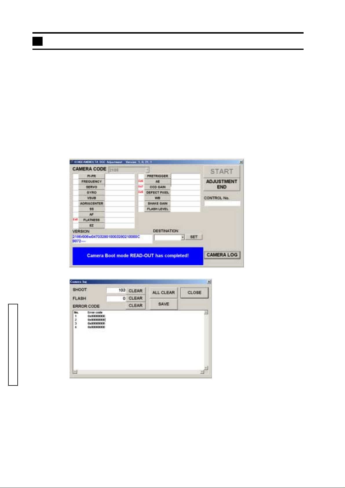
2. Click CAMERA LOGof the adjustment menu. (Fig. 1)
Check the items in the CAMERA LOG dialog. (Fig. 2)
■■
Fig. 1Fig. 1
■
Fig. 1
■■
Fig. 1Fig. 1
■■
Fig. 2Fig. 2
■
Fig. 2
■■
Fig. 2Fig. 2
TROUBLE-SHOOTING CHART
ERROR CODE: Refer to the error code list (listed in hex).
SHOOT: number of shutter-release for still images
FLASH: number of flash burst
SHOOT CLEAR: CLEAR THE SHUTTER-RELEASE LOG.
FLASH CLEAR: CLEAR THE FLASH BURST LOG.
ERROR CODE CLEAR: CLEAR THE ERROR CODE LOG.
ALL CLEAR: CLEAR THE LOG OF ERROR CODE, NUMBER OF RELEASE, AND
NUMBER OF FLASH BURST.
Page 3
(2)Trouble Code List
Condition Major Cause Camera
code
50
SCAM2 never become OFF within 150ms af ter charge mo to r
driving on mirror up.
52
FP pulse number is short m ore than 32 p uls e af te r ap er ture
stabilized.
53
SCAM1 never become ON wit hin 2s aft er charge mo tor
driving on charging.
54
SCAM2 never become ON wit hin 2s aft er charge mo tor
driving on charging.
56
XON already ON at t he beginning of releas e (be fo re m irr or Shutter undercharge
57
XON already ON just bef or e s ut te r re leas e. Shutter undercharge
58
XON never become ON between 1st curtain release and 2nd
curtain running complete.
59
XON become OFF when just before charging. (after about
18ms from 2nd curtain running
5A
FP-pulse never stop within 2s after aperture open drive Aperture mechanism NG.
5B
In aperture driving , FP pulse cannot reach a target pulse
within 130ms.
60
SCAM2 already OFF before mirror up d riving st art . Charge overrun in last
61
SCAM2 become OFF after final brake finished (moto r of f )
on charging.
B0
AF/MF cannot change within 2s after AFM motor driving
start.
01
ADT never output within 80μs on CCD 2nd initialization.
(Normaly, it comes within about 13μs)
02
Output of AE-IC (LMOUT) c annot be com e 2. 3V - 2. 6V.
(when battery on)
03
IO/IC standard voltage (1.55V) is out of range on FP gain
adjustment.
05
FP1 amplitude cannot reach the limit on FP gain
adjustment.
06
FP2 amplitude cannot reach the limit on FP gain
adjustment.
07
AFMPR amplitude cannot reach the limit on AFM gain
adjustment.
)
Charging mechanism NG. After all motors
Aperture mechanism NG.
Charging mechanism NG.
Charging mechanism NG.
Shutter undercharge
XON sw contact NG.
1st curtain rebound.
XON sw contact NG.
Aperture mechanism NG.
Aperture PI NG.
Charge overrun.
AF/MF PR NG.
AF/MF changeover
mechanism NG.
AF-CCD N G.
AF-FPC connection NG.
AE-IC NG.
AE-FPC connection NG.
IC304 NG.
Aperture PI NG.
Aperture PI-FPC connection
Aperture PI NG.
Aperture PI-FPC connection
AF/MF PR NG.
AF/MF PR-FPC connection
(2186) 3
Operation
brake for 50ms,
system down.
↑
↑
↑
↑
↑
↑
↑
↑
↑
↑
↑
↑
↑
↑
↑
↑
↑
↑
TROUBLE-SHOOTING CHART
Page 4

4 (2186)
Trouble Code List
Condition Major Cause Camera
code
30
Bilt-in flash charging err or. (charging cannot finish wi t hin
30s)
31
Built-in Flash cannot fir e. Fuse has blown.
32
Bilt-in flash charging err or. (voltage cannot reach 50V
within 5s)
33
Bilt-in flash charging err or. (2.75s later fr om once reach
290V, the voltage dropped bel ow 290V again)
A0
Unexpected Err on digital se ct io n (ASIC). Software probrem .
A1
Cannot receive r e ply from TEBURE IC. TEBURE IC NG.
Fuse has blown.
Flash charging circuit has
damaged.
IGBT NG.
Flash charging circuit has
damaged.
IGBT NG.
Fuse has blown.
Flash charging circuit has
damaged.
IGBT NG.
Fuse has blown.
Flash charging circuit has
damaged.
IGBT NG.
TEBURE IC connection NG.
Operation
After all motors
brake for 50ms,
system down.
↑
↑
↑
↑
↑
TROUBLE-SHOOTING CHART
Page 5

(2186) 5
TROUBLE-SHOOTING CHART
Page 6

6 (2186)
TROUBLE-SHOOTING CHART
Page 7

(2186) 7
TROUBLE-SHOOTING CHART
Page 8

8 (2186)
TROUBLE-SHOOTING CHART
Page 9

(2186) 9
TROUBLE-SHOOTING CHART
 Loading...