

Page 1

FrameMaker Ver.5.5(PC) AD-231 OPTION FOR 8020/8031
02.08.26
AD-231
SERVICE MANUAL
Page 2

FrameMaker Ver.5.5(PC) AD-231 OPTION FOR 8020/8031
02.08.26
Blank page
Page 3

FrameMaker Ver.5.5(PC) AD-231 OPTION FOR 8020/8031
02.08.26
CONTENTS
GENERAL,
MECHANICAL/ELECTRICAL
1. SPECIFICATIONS ...........................................................................................M-1
2. PARTS IDENTIFICATION ........................ ........................... ............................M-1
3. CROSS-SECTIONAL VIEW ............................................................................M-2
4. DRIVE SYSTEM ..............................................................................................M-3
5. ELECTRICAL COMPONENTS LAYOUT ........................................................M-3
6. MECHANICAL OPERATIONS .........................................................................M-4
6-1. Switchback Mechanism ...........................................................................M-4
(1) Switchback Operation ......................................................................M-4
(2) Paper Exit Roller Drive Coupling Mechanism . .................................M-4
(3) Switchback Motor Control ................................................................M-4
6-2. Transport and Duplex Paper Take-Up Mechanism .................................M-5
(1) Transport and Duplex Paper Take-Up Operation ............................ M-5
(2) Duplex Unit Transport Motor Contro l ............................. ..................M-5
6-3. 2-Sided Copying Method ......................................................................... M-6
(1) Operations in 2-sided copying with a single sheet
of paper resident in the system .......................................................M-6
(2) Operations in 2-sided copying with two sheets
of paper resident in the system .......................................................M-8
DIS/REASSEMBLY, ADJUSTMENT
1. DISASSEMBLY ...............................................................................................D-1
1-1. Maintenance Schedule ............................................................................D-1
1-2. Removal of the Duplex Unit ..................................................................... D-1
1-3. Cleaning of Duplex Unit Transport Roller 1 and 2 and Duplex Unit
Transport Roll 1 and 2 .............................................................................D-1
2. ADJUSTMENT .................................................................................................D-2
2-1. Changing the Cable Tension Strength (Replacement of the Spring) .......D-2
2-2. Reference Position Adjustment ............................... ........................... .....D-3
MISFEED DETECTION
1. MISFEED DETECTION .................................... ........................... ....................T- 1
1-1. Location of Misfeed Detecting Sensors ...................................................T-1
1-2. Misfeed Detection Timing ........ ............. ...... ...... ............. .... ............. ...... ...T-1
i
Page 4

FrameMaker Ver.5.5(PC) AD-231 OPTION FOR 8020/8031
02.08.26
Blank page
ii
Page 5

FrameMaker Ver.5.5(PC) AD-231 OPTION FOR 8020/8031
02.08.26
GENERAL,
MECHANICAL/ELECTRICAL
Page 6

FrameMaker Ver.5.5(PC) AD-231 OPTION FOR 8020/8031
02.08.26
Blank page
Page 7
FrameMaker Ver.5.5(PC) AD-231 OPTION FOR 8020/8031
02.08.26
1. SPECIFICATIONS
Type : Switchback and Circulating Duplex Unit
Installation : Mounted on the right side door of copier
Type of Copy Paper : Plain paper
Paper Sizes : A5L to A3Wide or 5-1/2 × 8-1/2L to 11 × 17L
Paper Weight :
Registration : Center
Power Requirements : DC24 V ± 10 %, DC5.1 V ± 5% (supplied from copier)
Max. Power Consumption : 17 W
Dimensions : Width ... 139 mm or 5-1/2 in
Weight : 3.1 kg or 6-3/4 lbs.
Environmental Requirements : Same as copier
64 to 90 g/m
Depth ... 440 mm or 17-1/4 in
Height ... 365 mm or 14-1/4 in
2
or 17 to 24 lbs.
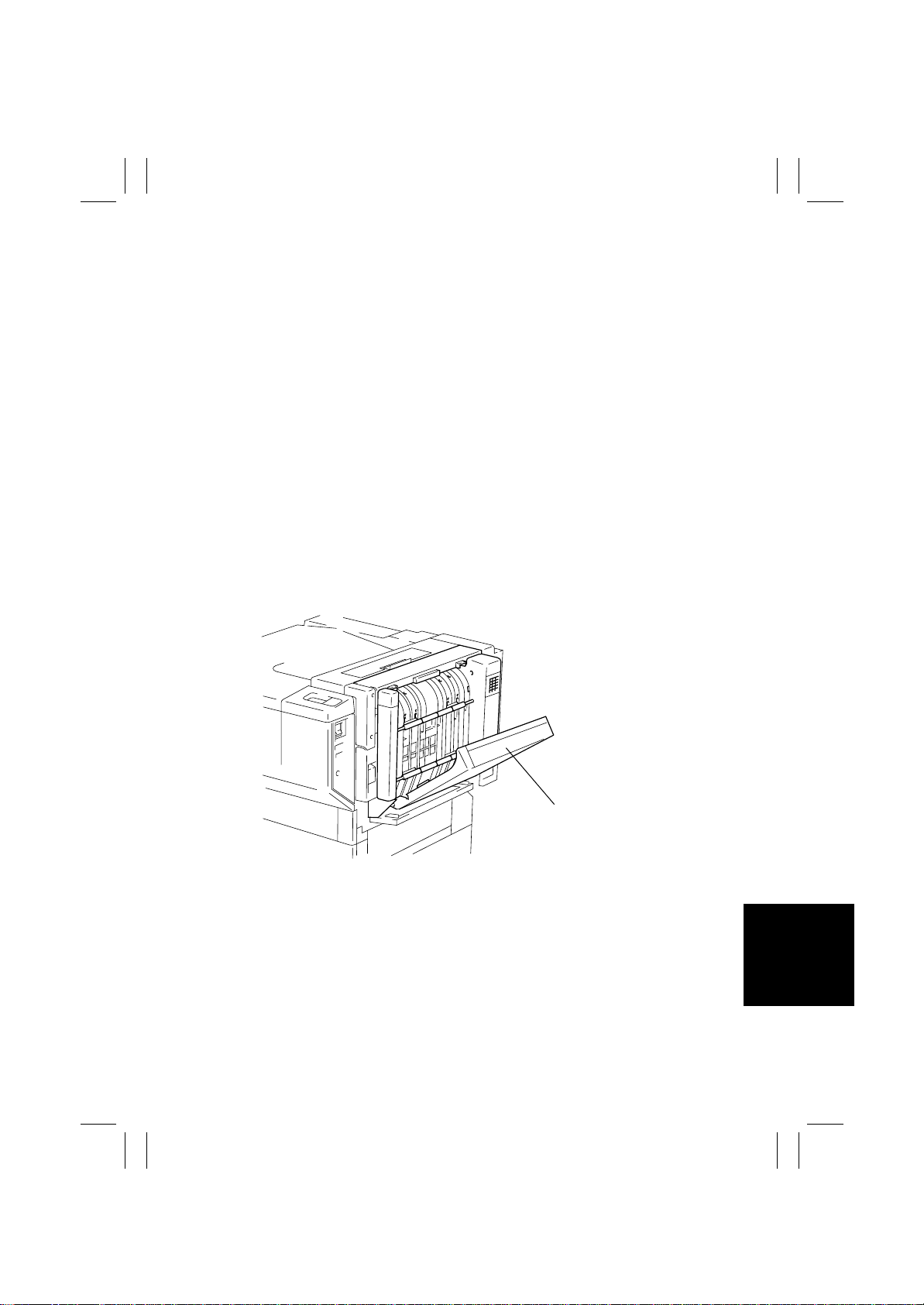
2. PARTS IDENTIFICATION
M-1
Duplex Unit Door
4657M001AA
Page 8
FrameMaker Ver.5.5(PC) AD-231 OPTION FOR 8020/8031
02.08.26
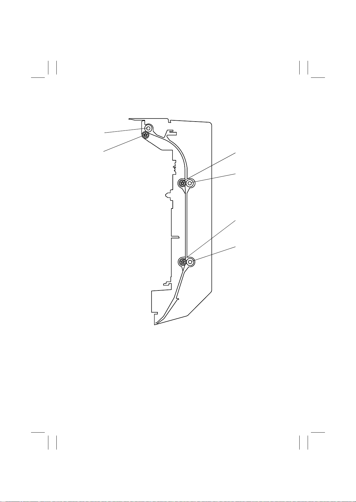
3. CROSS-SECTIONAL VIEW
6
5
1
2
3
4
4657M002AA
1. Duplex Unit Transport Roll 2
2. Duplex Unit Transport Roller 2
3. Duplex Unit Transport Roll 3
4. Duplex Unit Transport Roller 3
5. Duplex Unit Transport Roll 1
6. Duplex Unit Transport Roller 1
M-2
Page 9
FrameMaker Ver.5.5(PC) AD-231 OPTION FOR 8020/8031
02.08.26
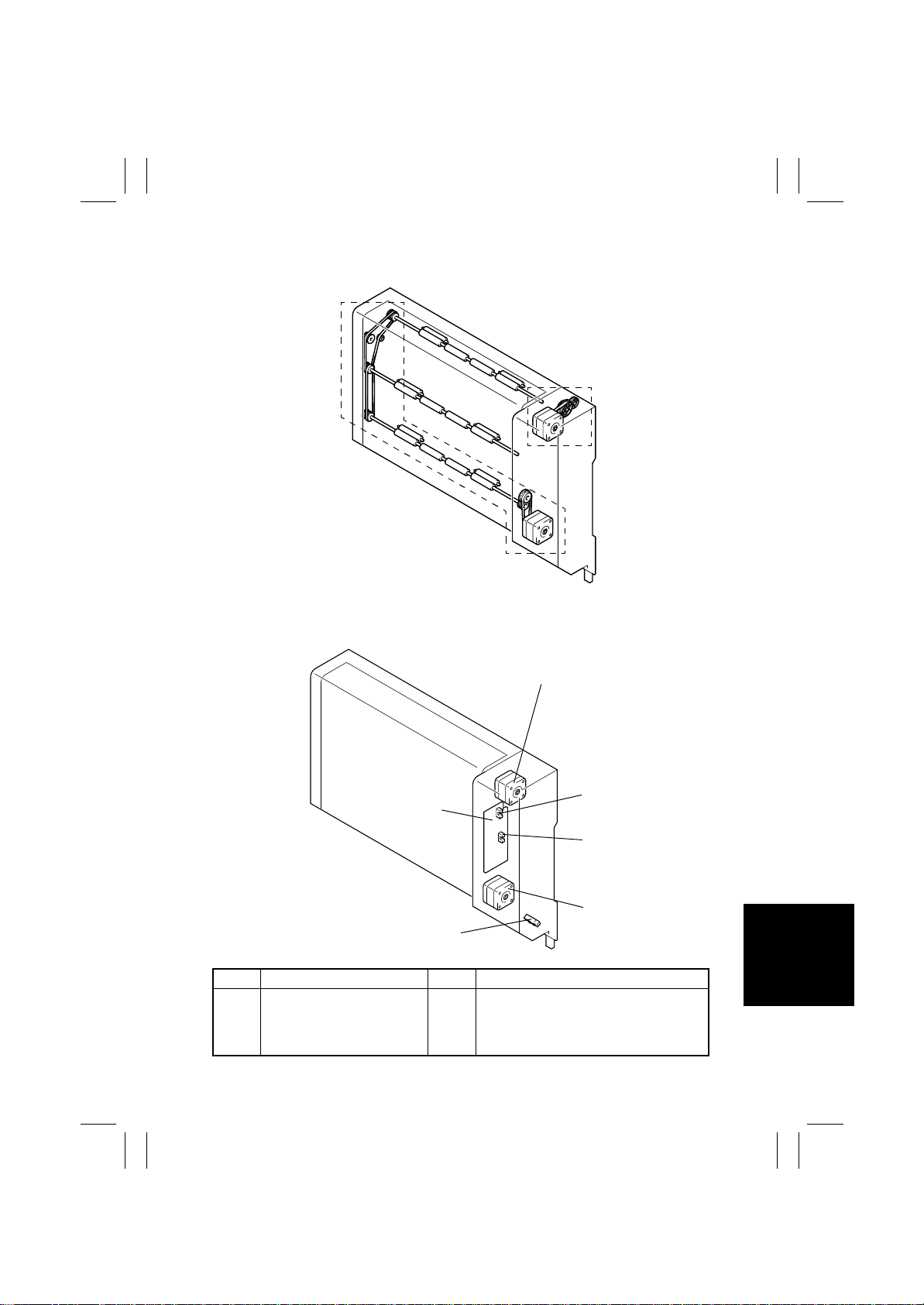
4. DRIVE SYSTEM
Duplex Unit Transport
Drive Mechanism
Switchback Drive
Mechanism
4657M003AA
5. ELECTRICAL COMPONENTS LAYOUT
M1
PWB-A
PC1
Symbol Name Symbol Name
PWB-A
Duplex Control Board
M1
Switchback Motor
M2
Duplex Unit Transport Motor
PC1
Duplex Unit Transport Sensor 2
PI1
Duplex Unit Transport Sensor 1
(in PWB-A)
PI2
Duplex Unit Door Set Sensor (in PWB-A)
PI2
PI1
M2
4657M004AB
M-3
Page 10
FrameMaker Ver.5.5(PC) AD-231 OPTION FOR 8020/8031
02.08.26
6. MECHANICAL OPERATIONS
6-1. Switchback Mechanism
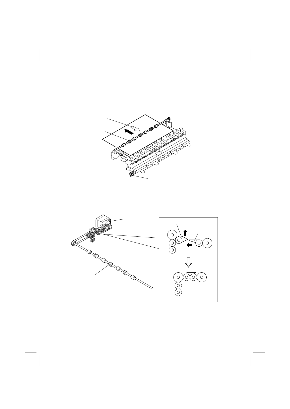
(1) Switchback Operation
The Paper Exit Roller of the copier is used to subject the 1-sided copy to a switchback
sequence so that the 1-sided copy is to be transported through the Duplex Unit.
Feeding the Paper into Duplex Unit
Paper Exit Roller
Paper Exit Sensor PC10
(2) Paper Exit Roller Drive Coupling Mechanism
When the Duplex Unit is mounted, the tip of the Duplex Unit Lever raises the Idle Lever to
cut off the drive from the copier (Fusing Rollers) and the Paper Exit Roller is driven by the
Switchback Motor.
Switchback Motor
M1
Paper Exit Roller
(3) S w itchback Motor Control
Rotation of the Switchback Motor is controlled by the signals output from pins 1 to 4 of
PJ2A on the Duplex Control Board.
Idle Lever
4657M005AB
Duplex Unit
Lever
4657M514AA4657M526AA
M-4
Page 11
FrameMaker Ver.5.5(PC) AD-231 OPTION FOR 8020/8031
02.08.26
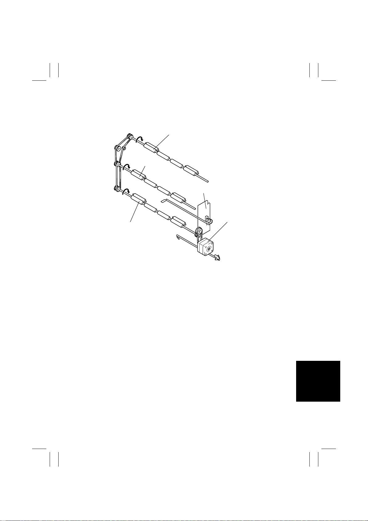
6-2. Transport and Duplex Paper Take-Up Mechanism
(1) Transport and Duplex Paper Take-Up Operati on
Drive for the Duplex Unit is provided by the Duplex Unit Transport Motor.
Duplex Unit Transport Roller 1
Duplex Unit
Transport Roller 2
Duplex Control Board PWB-A
Duplex Unit Transport
Duplex Unit Transport Roller 3
Motor M2
4657M007AB
(2) Duplex Unit Tran sp ort Motor Control
Rotation of the Duplex Unit Transport Motor is controlled by the signals output from pins 1
to 4 of PJ3A on the Duplex Control Board.
M-5
Page 12

FrameMaker Ver.5.5(PC) AD-231 OPTION FOR 8020/8031
2
02.08.26
6-3. 2-Sided Copying Method
• The following two types of 2-sided copying methods are available.
2-sided copying with a single sheet of paper resident
2-Sided Copying Methods
(1) Operations in 2-sided copying with a single sheet of paper resident in the sys-
tem
in the system
2-sided copying with two sheets of paper resident in
the system (FD length 215.9 mm or less)
Operation 1
• The first sheet of paper is taken up and fed in from the
copier drawer and the copier starts the first copy cycle to
produce the copy image of the second page of the original.
Operation 2
• Immediately before the 1-sided copy leaves the Paper Exit
Roller, the direction of rotation of the Paper Exit Roller is
reversed and the 1-sided copy is transported toward and
into the Duplex Unit.
Operation 3
• The 1-sided copy moves through the Duplex Unit and is
directly subject to the second copy cycle without being
stopped.
Paper Exit
Roller
2
4657M521AA
4657M522AA
2
4657M523AA
M-6
Page 13
FrameMaker Ver.5.5(PC) AD-231 OPTION FOR 8020/8031
1 2
1
2
4
02.08.26
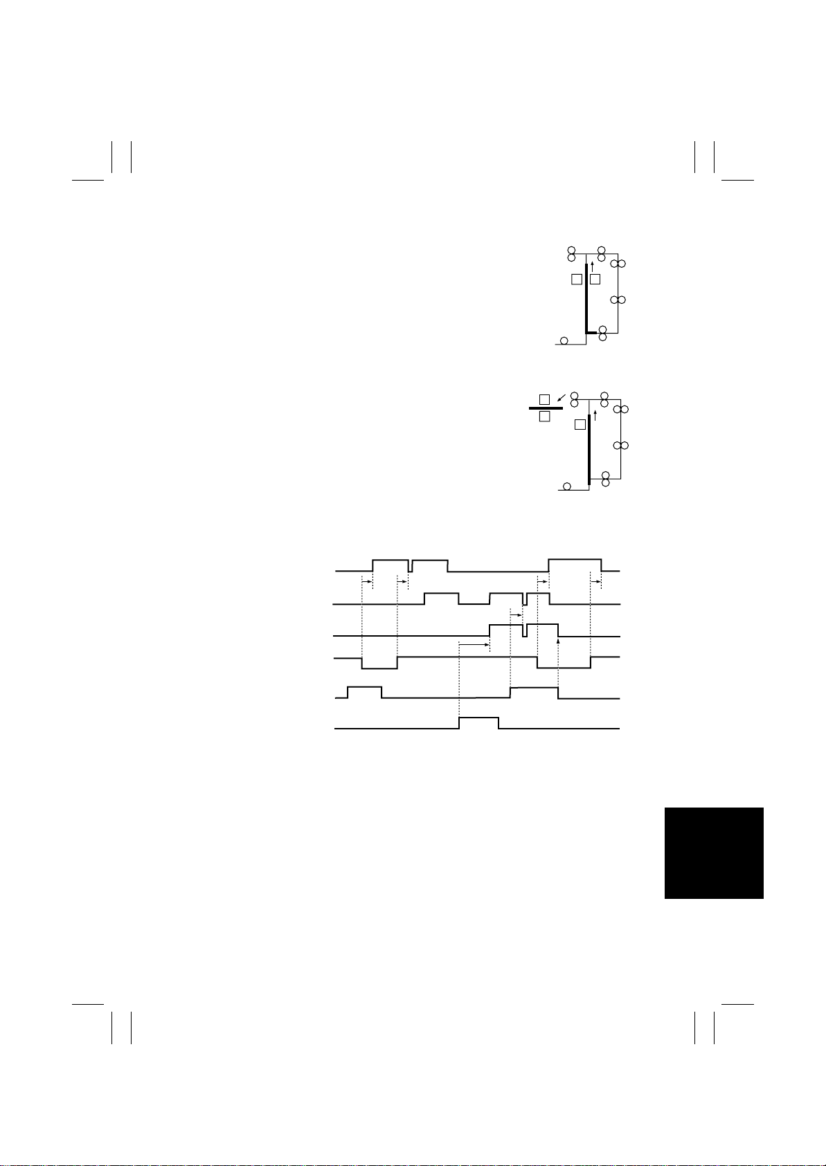
Operation 4
• The copier carries out the second copy cycle to produce
the copy image of the first page of the original on the other
side of the 1-sided copy.
Operation 5
• While feeding the first 2-sided copy out of itself, the copier
carries out the first copy cycle for the second sheet of
paper to produce the copy image of the fourth page of the
original.
✽
Steps 2 through 5 are repeated.
4657M524AA
4657M525AA
witchback Motor
1
uplex Unit
ransport Motor M2
anual Feed Paper
ake-Up Clutch CL3
xit Sensor PC10
ynchronizing Roller
ensor PC17
uplex Unit Transport
ensor 2 PC1
ON
OFF
ON
OFF
ON
OFF
H
L
H
L
H
L
Forward
Rotation
Backward
Rotation
Forward
Rotation
4657M513CA
M-7
Page 14

FrameMaker Ver.5.5(PC) AD-231 OPTION FOR 8020/8031
2
2
1
2
3
4
02.08.26
(2) Operations in 2-sided copying with two sheets of paper resident in the system
Operation 1
• The first sheet of paper is taken up and fed in from the
copier drawer and the copier starts the first copy cycle to
produce the copy image of the second page of the original.
Operation 2
• Immediately before the first 1-sided copy leaves the Paper
Exit Roller, the direction of rotation of the P aper Exit Roller
is reversed and the first 1-sided copy is transported toward
and into the Duplex Unit.
• At the same time, the second sheet of paper is taken up
and fed into the copier.
Operation 3
• The copier carries out the first cop y cycle for the second
sheet of paper to produce the copy image of the fourth
page of the original.
• At the same time, the first 1-sided copy is transported
through the Duplex Unit.
Paper Exit
Roller
4657M515AA
4657M516AA
4
2
4657M517AA
Operation 4
• The copier produces the copy image of the first page of the
original on the first 1-sided copy that has been fed through
the Duplex Unit.
142
• At the same time, the second sheet of paper is subjected
to a switchback sequence at the exit section and fed into
the Duplex Unit. It is then fed through the Duplex Unit without being stopped and into the copier again.
4657M518AA
Operation 5
• While feeding the first sheet of paper out, the copier carries
out a copy cycle for the second sheet of paper to produce
the copy image of the third page of the original.
4657M519AA
M-8
Page 15

FrameMaker Ver.5.5(PC) AD-231 OPTION FOR 8020/8031
3
4
6
1
2
02.08.26
Operation 6
• While feeding the second sheet of paper out, the copier
takes up and feeds the third sheet of paper to produce the
copy image of the sixth page of the original on the third
sheet of paper.
✽
Steps 2 through 6 are repeated.
4657M520AA
M-9
Page 16

FrameMaker Ver.5.5(PC) AD-231 OPTION FOR 8020/8031
02.08.26
Blank page
M-10
Page 17

FrameMaker Ver.5.5(PC) AD-231 OPTION FOR 8020/8031
02.08.26
DIS/REASSEMBLY,
ADJUSTMENT
Page 18

FrameMaker Ver.5.5(PC) AD-231 OPTION FOR 8020/8031
02.08.26
Blank page
Page 19
FrameMaker Ver.5.5(PC) AD-231 OPTION FOR 8020/8031
02.08.26
1. DISASSEMBLY
1-1. Maintenance Schedule
• To ensure good copies and an extended service life of the Duplex Unit, it is recommended that the maintenance jobs described in this schedule be carried out.
Maintenance
PM Parts
Duplex Unit Transport Roller 1, 2
Duplex Unit Transport Roll 1, 2
✽
Cleaning (indicated by “❍” in the above schedule) should be performed when a paper
transport failure occurs.
✽
The above information is subject to change without notice.
Schedule Cycle
Clean Replace
❍
❍
Tools
Used for
Cleaning
–
Cloth,
alcohol
––4
Parts No. QTY
– 2
Reference
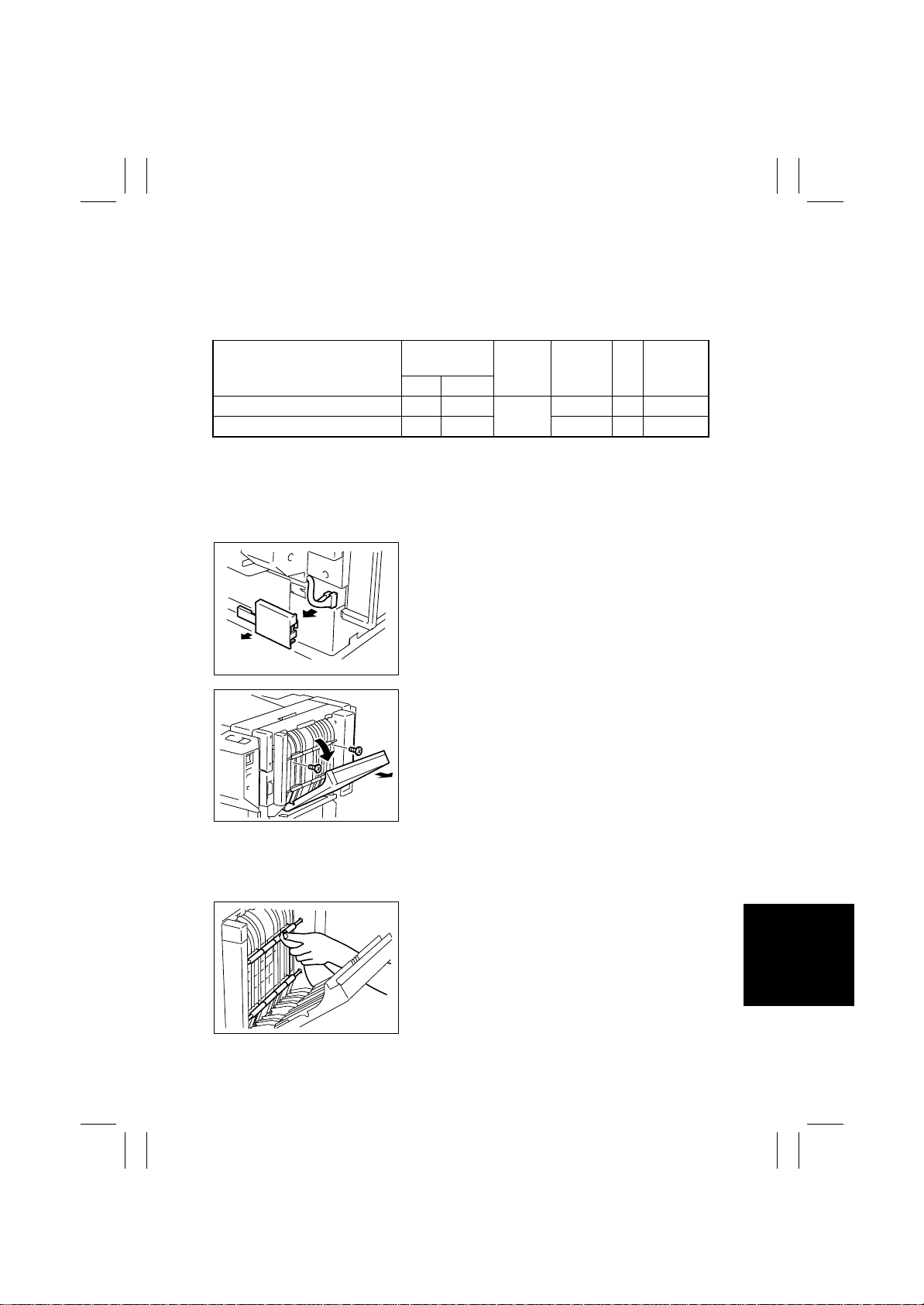
1-2. Removal of the Duplex Unit
1. Remove the wiring cover and disconnect two connectors.
4657D001AA
2. Open the Duplex Unit Door.
3. Remove two shoulder screws and the Duplex Unit.
Page
☞
☞
D-1
D-1
4657D002AA
1-3. Cleaning of Duplex Unit Transport Roller 1 and 2 and Duplex
Unit Transport Roll 1 and 2
1. Open the Duplex Unit Door.
2. Wipe the surfaces of Duplex Unit Transport Roller
1 and 2 and Duplex Unit Transport Roll 1 and 2
clean with a soft cloth dampened with alcohol.
4657D003AA
D-1
Page 20
FrameMaker Ver.5.5(PC) AD-231 OPTION FOR 8020/8031
02.08.26
2. ADJUSTMENT
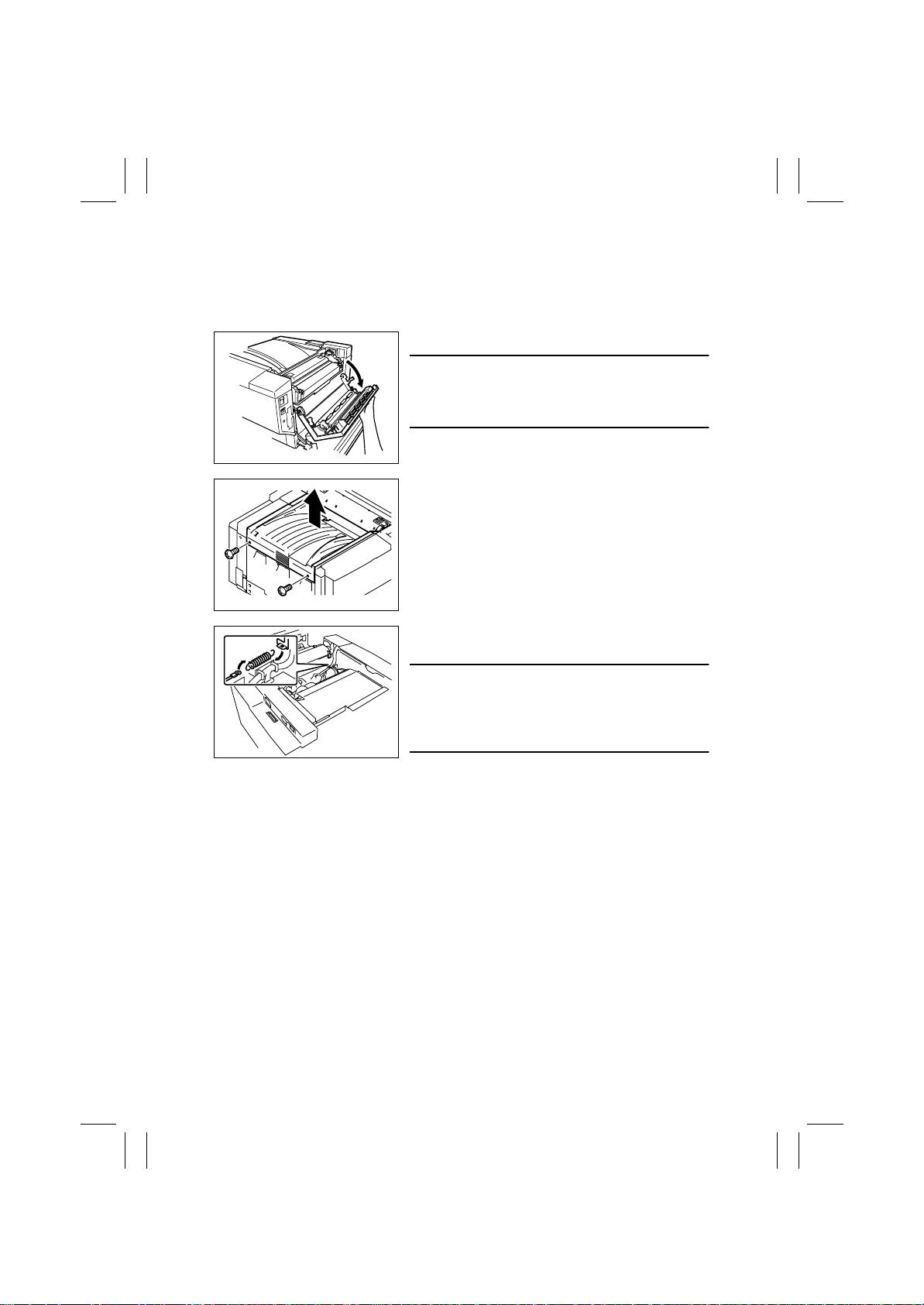
2-1. Changing the Cable Tension Strength (Replacement of the
Spring)
1. Open the Upper Right Door of the copier.
NOTE
• Do not jerk the Upper Right Door open, as a mal-
function could result. Be sure to hold onto the door
with both hands and open it gently.
4657D503AA
2. Remove two screws and the Exit Cover of the
copier.
4657D006AA
4657D007AA
3. Remove the spring and, instead, install the spring
furnished with the Duplex Unit in position.
NOTE
• When the Duplex Unit is mounted, the Right Door of
the copier can jerk open by its own weight as it is
opened, damaging the copier. Be sure to replace the
spring to change the tension strength of the cable.
D-2
Page 21
FrameMaker Ver.5.5(PC) AD-231 OPTION FOR 8020/8031
02.08.26
2-2. Reference Position Adjustment
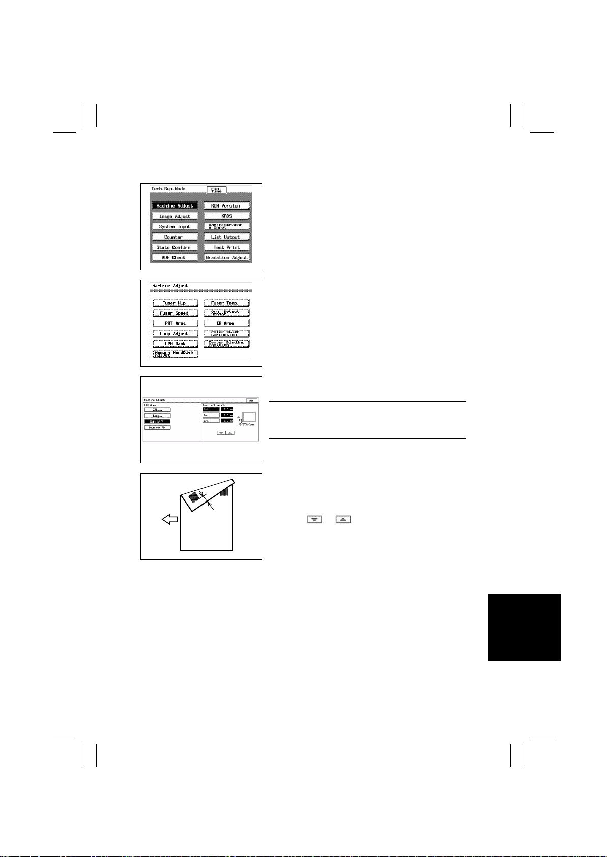
1. Press the Utility key and touch “Meter Count.”
2. Press the following keys in this order to show the
Tech. Rep. mode screen: Stop → 0 → 0 → Stop →
0 → 1.
3. Touch “Machine Adjust.”
k4659P004CA
4. Touch “PRT Area.”
4659P005CA
5. Touch “Dup. Left Margin.”
6. Touch “1st.”
Feeding
Direction
4657D201AA copy
A
4657D502AA
NOTE
• Use the same procedures that follow for “2nd,” “3rd,”
and “4th.”
7. Press the Start key to produce a test print.
8. Measure dimension A on the second side to see if
it falls within the specifications.
✽
Specifications: 3.0 ± 1.0 mm
9. Using or key, input the difference
between the measured value of dimension A and
the specifications.
10. Produce another test print and make a check
again.
D-3
Page 22

FrameMaker Ver.5.5(PC) AD-231 OPTION FOR 8020/8031
02.08.26
Blank page
D-4
Page 23

FrameMaker Ver.5.5(PC) AD-231 OPTION FOR 8020/8031
02.08.26
MISFEED DETECTION
Page 24

FrameMaker Ver.5.5(PC) AD-231 OPTION FOR 8020/8031
02.08.26
Blank page
Page 25
FrameMaker Ver.5.5(PC) AD-231 OPTION FOR 8020/8031
02.08.26
1. MISFEED DETECTION
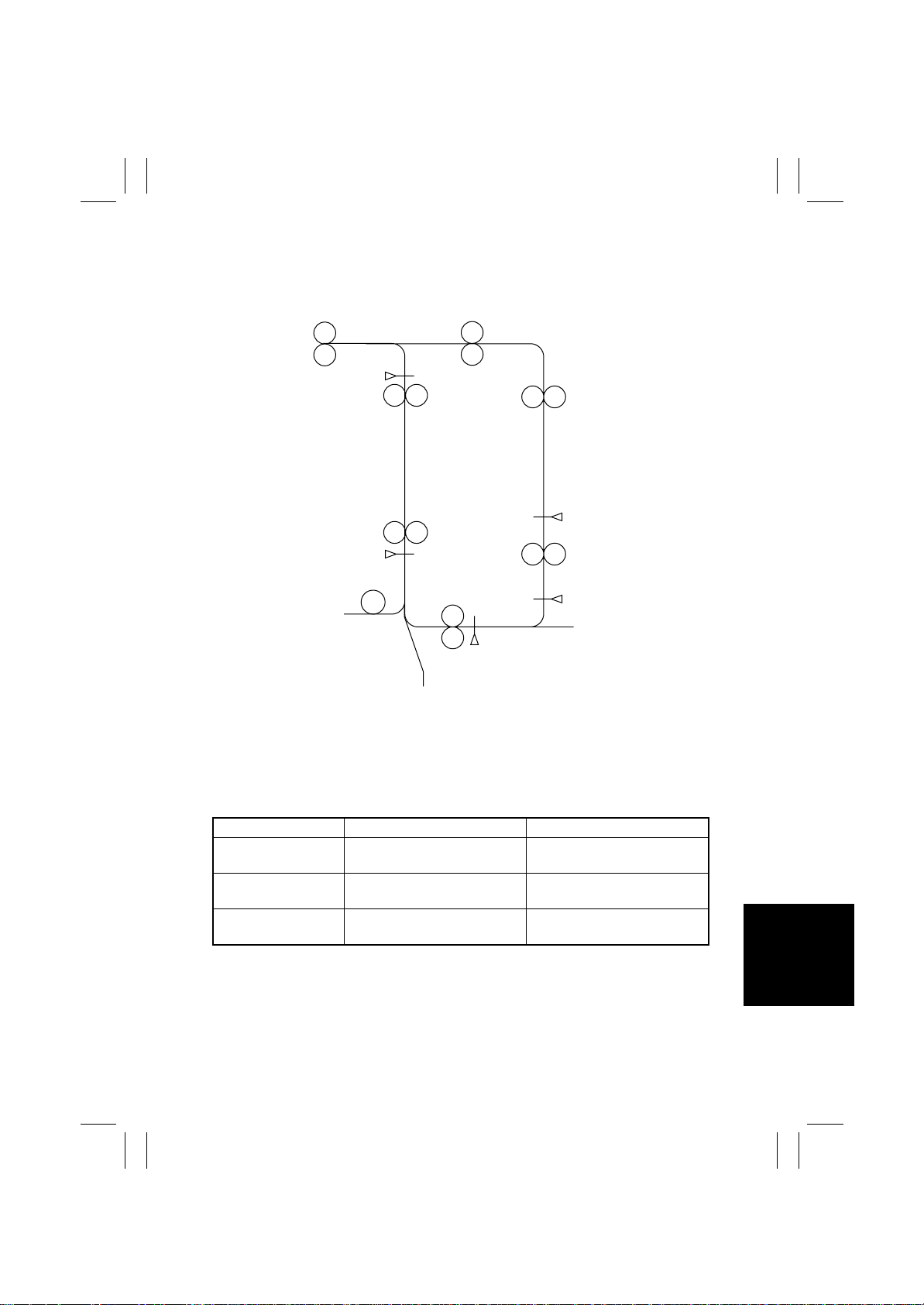
1-1. Location of Misfeed Detecting Sensors
Synchronizing Roller Sensor
PC17
Duplex Unit Transport
Sensor 1 PI1
Duplex Unit Transport
Sensor 2 PI2
4657T501AA
1-2. Misfeed Detection Timing
• The following lists the types of misfeed detection and detection timings for different misfeed locations.
• The symbol “L” (for the leading edge) and “T” (for the trailing edge) given in ( ) indicate
the particular edge of the paper detected by the sensor.
Type Detection Start Detection
Paper left Power Switch ON
Paper take-up fail ure
Misfeed during
transport through unit
Manual Feed Paper Take-Up
Clutch ON
Duplex Unit Transport Sensor 1
(L)
Duplex Unit Transpor t Sensor 1
ON
Synchronizing Roller Sensor (L)
Duplex Unit Transpor t Sensor 2
(L)
T-1
Page 26

FrameMaker Ver.5.5(PC) AD-231 OPTION FOR 8020/8031
02.08.26
Blank page
T-2
 Loading...