

Page 1

FrameMaker Ver.5.5E(PC) 8020/8031 TROUBLESHOOT ING
02.08.19
TR OUBLESHOOTING
Page 2

FrameMaker Ver.5.5E(PC) 8020/8031 TROUBLESHOOT ING
02.08.19
Blank page
Page 3
FrameMaker Ver.5.5E(PC) 8020/8031 TROUBLESHOOT ING
02.08.19
1. INTRODUCTION
• Information required for troubleshooting and steps that must be performed are described
in this chapter.
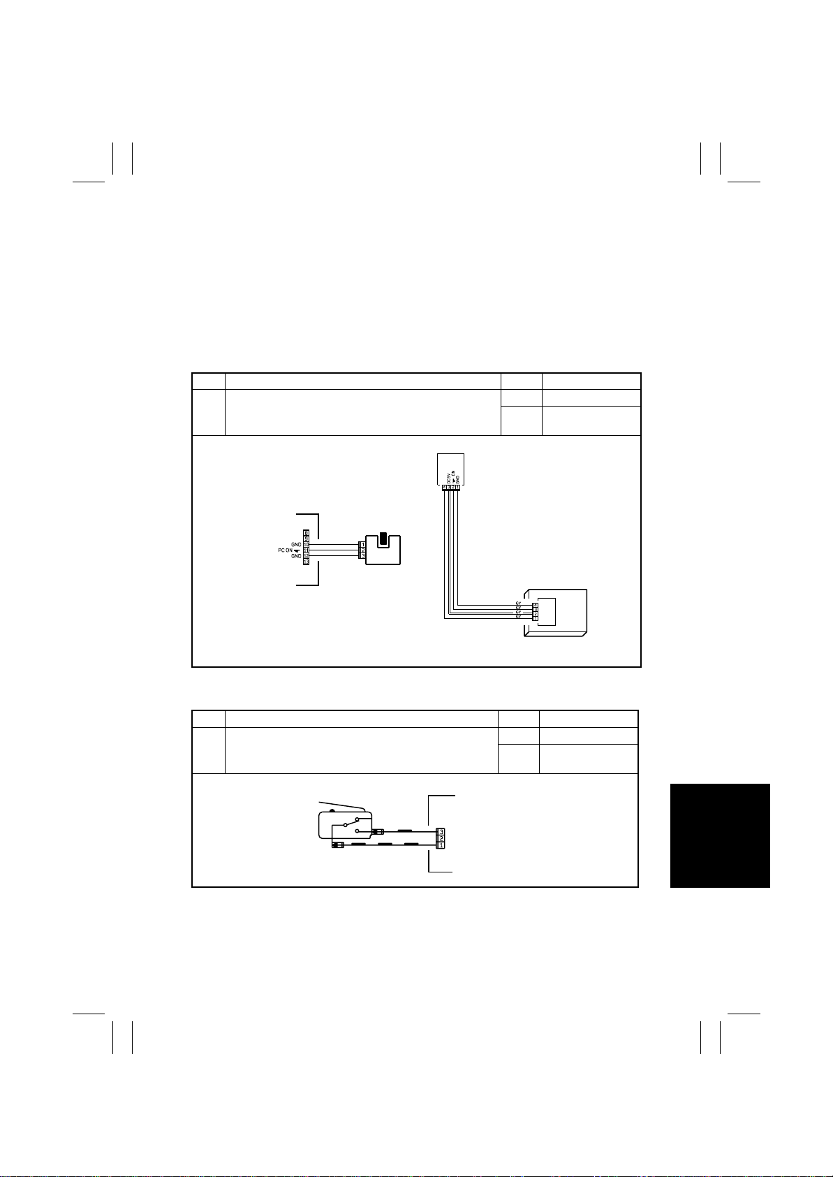
1-1. Checking the electrical components
• If a paper misfeed or malfunction occurs, perform the following operation to check the
condition of the electrical components.
(1) Sensor
Step Check Result Action
Does the input signal of the master board change (H→L,
1
L→H) when the sensor light is interrupted?
NO Replace the sensor.
Replace the control
YES
board.
4025T520AA
4025T521AA
(2) Switch
Step Check Result Action
Does the input signal (NO) of the master board change from
1
L to H when the switch is turned on?
COM
Not Use
NO
NO Replace the switch.
Replace the control
YES
board.
4025T523AA
T-1
Page 4
FrameMaker Ver.5.5E(PC) 8020/8031 TROUBLESHOOT ING
02.08.19
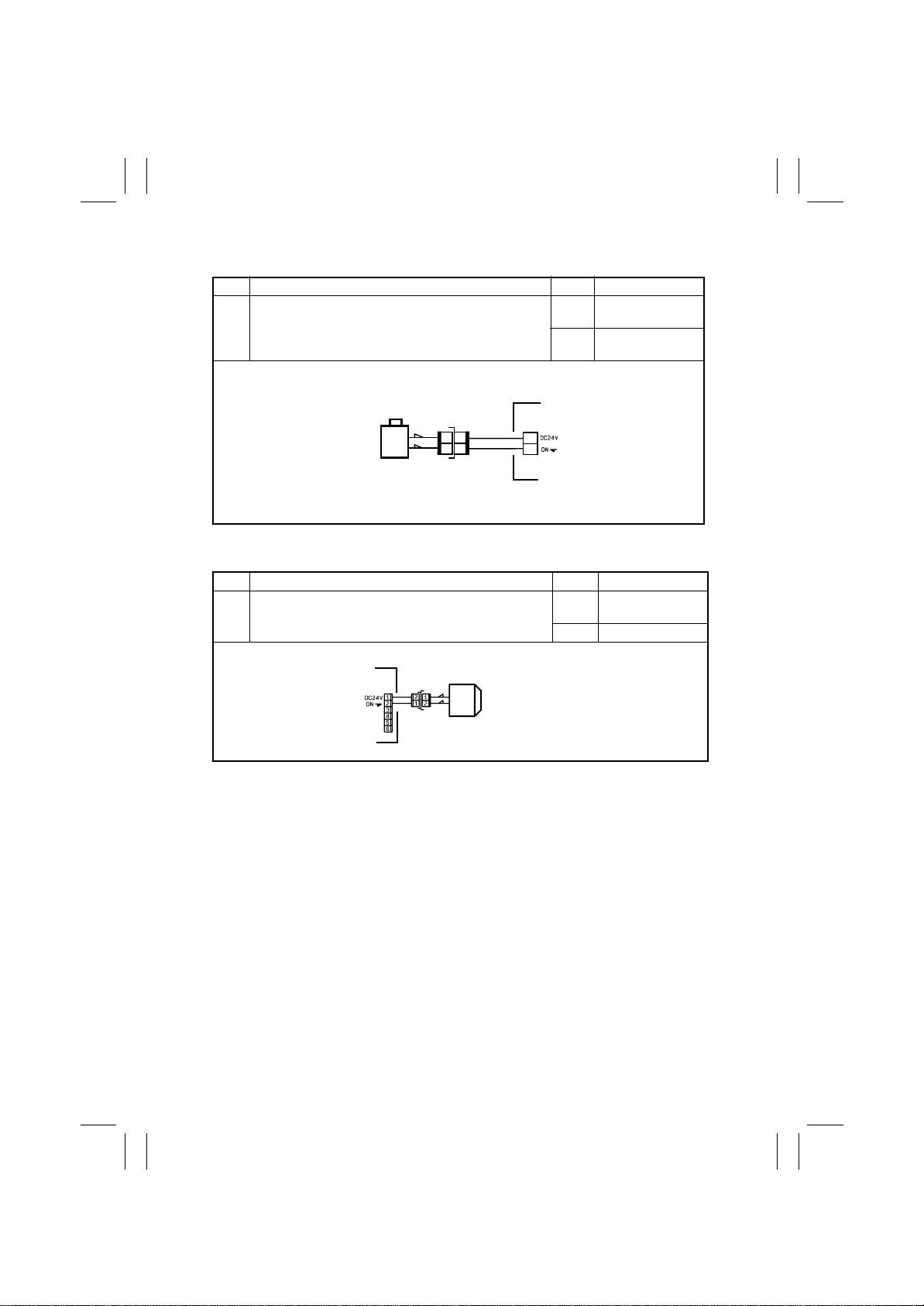
(3) Solenoid
Step Check Result Action
Replace the control
NO
YES
board.
Replace the sole-
noid.
Does the output signal of the master board change from H to
1
L when the solenoid is turned on?
2
1
1
2
1
2
4025T522AA
(4) Clutch
Step Check Result Action
Replace the control
Does the output signal of the master board change from H to
1
L when the clutch is activated?
NO
board.
YES Replace the clutch.
T-2
4025T528AA
Page 5
FrameMaker Ver.5.5E(PC) 8020/8031 TROUBLESHOOT ING
02.08.19
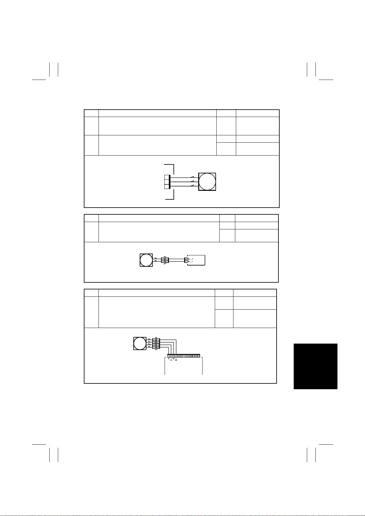
(5) Motor
Step Check Result Action
Does the LOCK signal switch to H when the machine goes
1
into standby?
Does the REM signal of the master board change from H to
2
L when the motor is turned on?
1
GND
2
REM
LOCK
3
4025T526AA
Step Check Result Action
Does the input signal of the master board change from H to L
1
when the motor is turned on?(The input signal differs depending on the rotation direction.)
Replace the control
NO
board. Replace the
motor.
YES Replace the motor.
Replace the control
NO
board.
YES Replace the motor.
Replace the control
NO
board.
4025T525AA
Step Check Result Action
Replace the motor
YES
Are the relay connector of the motor and the print jack on
1
the master board correctly connected?
or the control board.
Connect the con-
NO
nector or the print
jack.
4025T527AA
T-3
Page 6

FrameMaker Ver.5.5E(PC) 8020/8031 TROUBLESHOOT ING
02.08.19
1-2. I/O CHECK
(1) Check Procedure
To allow sensors to be check ed for operation easily and safel y, data applied to the IC on the
board can be checked on the panel with the copier in the standby state (including a misfeed, malfunction, and closure failure condition).
<Electrical Components Check Procedure Through Input Data Check>
Example
When a paper misfeed occurs in the paper take-up section of the copier, the 2nd Drawer
Paper Take-Up Sensor is considered to be responsible for it.
<Procedure>
1. Remove the sheet of paper misfeed.
2. From the I/O Check List that follows, check the panel display of the 2nd Drawer Paper
Take-Up Sensor. For the 2nd Drawer Paper Take-Up Sensor, you check the data of
“Take- Up” of “2nd Drawer.”
3. Call the Tech. Rep. mode to the screen.
→
4. Select “State Confirm”
Up” under “2nd Drawer.” For “Take-U p” under “2nd Drawer,” select “1” on the left-hand
side of the screen.
5. Check that the data for “Take-Up ” under “2nd Drawer” is “0” (sensor blocked).
6. Move the actuator to unblock the 2nd Drawer Paper Take-Up Sensor.
7. Check that the data for “Take-Up ” under “2nd Drawer” changes from “0” to “1” on the
screen.
8. If the input data is “0,” change the sensor.
“I/O Check” and then select the screen that contains “Take-
T-4
Page 7
FrameMaker Ver.5.5E(PC) 8020/8031 TROUBLESHOOT ING
02.08.19
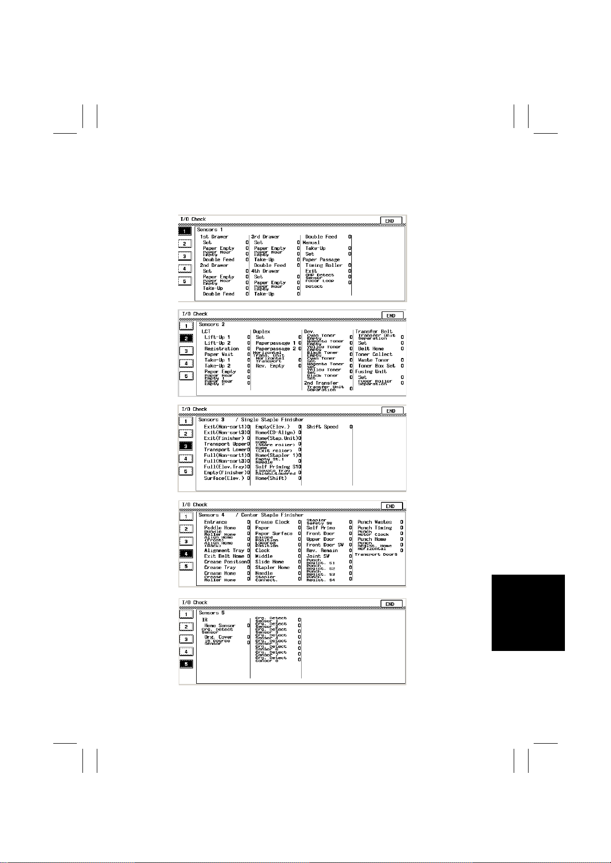
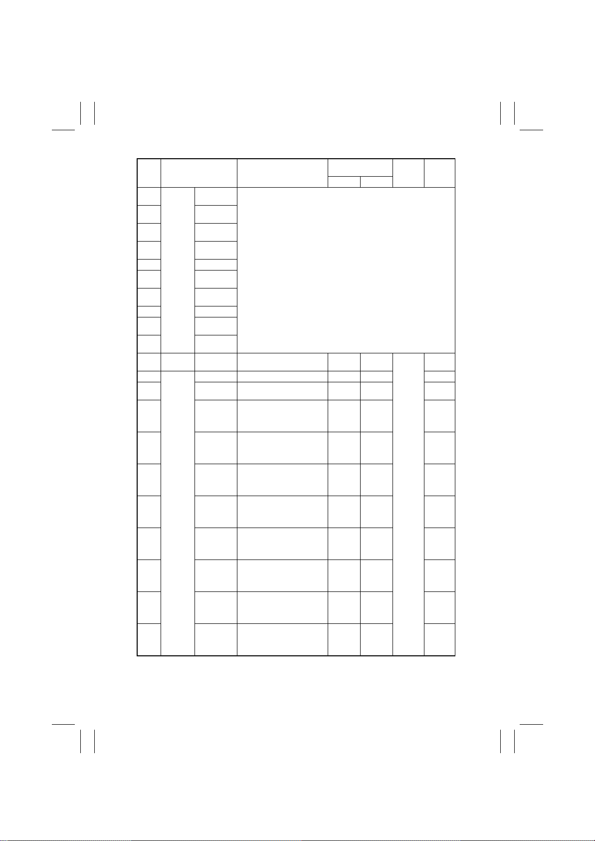
(2) I/O Check List
<I/O Check Screens>
• These are only typical screens which may be different f rom what are shown on each individual copier.
4025T560CA
k4025T561CA
4025T562CA
4025T563CA
4025T564CA
T-5
Page 8
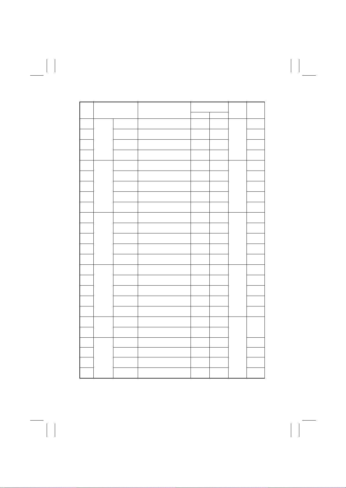
FrameMaker Ver.5.5E(PC) 8020/8031 TROUBLESHOOT ING
02.08.19
<I/O Check List>
Operation Characteris-
Symbol Panel Display Part/Signal Name
PC3 1st Drawer Set 1st Dr awer Set
PC6 Paper Empty 1st Drawer Paper Empty Sensor Paper not
PC4 Paper Near
PC13 Double Feed 1st Drawer Double Feed Sensor Paper
SW D 2nd
Drawer
PC102 Paper Empty 2nd Drawer Paper Empty Sen-
PC103 Paper Near
PC101 Take-Up 2nd Drawer Paper Take-Up Sen-
PC105 Double Feed 2nd Dra we r Doub l e Feed Sensor Paper
SW D 3rd Drawer Set Drawer Set Switch In position Out of
PC2 Paper Empty Drawer Paper Empty Sensor Paper not
PC3 Paper Near
PC1 Take-Up Drawer Paper Take-Up Sensor Paper
PC5 Double Feed Drawer Double Feed Sensor Paper
SW D 4th Drawer Set Drawer Set Switch In position Out of
PC2 Paper Empty Drawer Paper Empty Sensor Paper not
PC3 Paper Near
PC1 Take-Up Drawer Paper Take-Up Sensor Paper
PC5 Double Feed Drawer Double Feed Sensor Paper
PC15 Manual Take-Up Manual Feed Paper Take-Up
PC15 Set Manual Feed Paper Take-Up
PC17 Paper
Passage
PC10 Exit Exit Sensor Paper
PC19 OHP Detect
PC9 Fuser Loop
Empty
Empty
Empty
Empty
Timing Roller Synchronizing Roller Sensor Paper
Sensor
Detect
Sensor
1st Drawer Paper Near-Empty
Sensor
Set 2nd Drawer Set Switch In position Out of
sor
2nd Drawer Paper Near-Empty
Sensor
sor
Drawer Paper Near-Empty Sensor
Drawer Paper Near-Empty Sensor
Sensor
Sensor
OHP Detecting
Sensor
Fusing Paper Loop Detecting
Sensor
tics/Panel Display
10
In position Out of
present
Blocked Unblocked PJ18IO-
present
Paper not
present
Blocked Unblocked PJ3A-11A
Paper
present
present
present
Blocked Unblocked PJ3A-11A
present
present
present
Blocked Unblocked PJ3A-11A
present
present
Paper
present
In position Out of
present
present
present
present
OHP
Loop
position
Paper
present
Paper not
present
position
Paper
present
Paper not
present
Paper not
present
position
Paper
present
Paper not
present
Paper not
present
position
Paper
present
Paper not
present
Paper not
present
Paper not
present
position
Paper not
present
Paper not
present
OHP not
present
Loop not
present
Input
Board
IO Board
(PWB-IO)
2nd
Drawer
Control
Board
(PWB-A)
3rd
Drawer
Control
Board
(PWB-A)
4th
Drawer
Control
Board
(PWB-A)
IO Board
(PWB-IO)
CN/PJ
No.
PJ18IO-
6B
PJ11IO-
3A
3B
PJ11IO-
5B
PJ3A-4B
PJ3A-14A
PJ3A-5A
PJ3A-8A
PJ3A-4B
PJ3A-14A
PJ3A-5A
PJ3A-8A
PJ3A-4B
PJ3A-14A
PJ3A-5A
PJ3A-8A
PJ10IO-2
PJ3IO-9B
PJ11IO-
9A
PJ3IO-2B
PJ4IO-14
T-6
Page 9
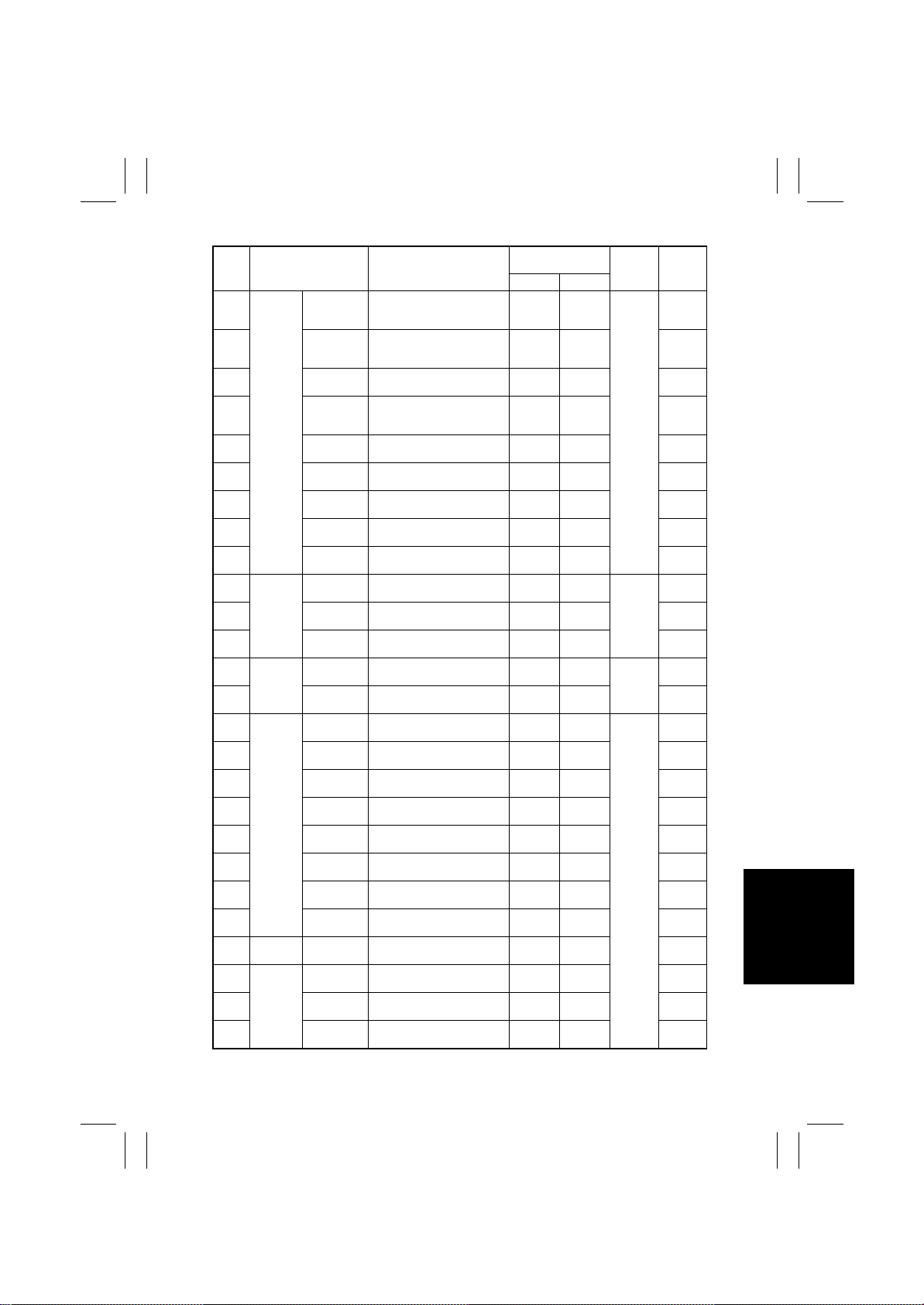
FrameMaker Ver.5.5E(PC) 8020/8031 TROUBLESHOOT ING
02.08.19
Operation Characteris-
Symbol Panel Display Part/Signal Name
LS1 LCT Lift-Up 1 Lift-Up Sensor 1 At raised
LS2 Lift-Up 2 Lift-Up Sensor 2 At raised
RSEN Registration Registration Sensor Paper
S1 Paper Wait Paper Standby
PPS0 Take-Up 1 LCT Paper Take-Up Sensor Paper
PPS1 Take-Up 2 Paper Empty Sensor 1 Paper
EMP Paper Empty Paper Empty Sensor 2 Paper not
RS1 Paper Near
RS2 Paper Near
PWB-A
Duplex Set Duplex Unit Door Set Sensor (in
PI2
PWB-A
PI1
PC1 Paper
PC1 Horizontal
Trans. Unit
PC6 Rev. Empty Turnover Empty Detecting Sen-
PC45 Dev. Cyan Toner
PC43 Magenta
PC41 Yellow Toner
PC47 Black Toner
PC50 Cyan Toner
PC49 Magenta
PC48 Yellow Toner
PC51 Black Toner
PC23 2nd
Transfer
PC28 Transfer
PC12 Belt Home Image Transfer Belt Reference
Belt
- Set - In position Out of
Empty 1
Empty 2
Paper
passage 1
passage 2
Horizontal
Transport
Empty
Toner Empty
Empty
Empty
Toner Set
Transfer Unit
Separation
Transfer Unit
Separation
Position Sensor
Paper Near Empty Sensor 1 Unblocked Blocked CN6A-12
Paper Near Empty Sensor 2 Unblocked Blocked CN5A-5
PWB-A)
Duplex Unit
Transport Sensor 1 (in PWB-A)
Duplex Unit
Transport Sensor 2
Paper Sensor Paper not
sor
Toner Near-Empty Sensor PQ C Toner not
Toner Near-Empty Sensor PQ M Toner not
Toner Near-Empty Sensor PQ Y Toner not
Toner Near-Empty Sensor PQ BkToner not
TC Set Sensor C Out of
Set
TC Set Sensor M Out of
TC Set Sensor Y Out of
Set
TC Set Sensor Bk Out of
Set
2nd Image Transfer Pressure
Position Sensor
1st Image Transfer Retraction
Position Sensor
Position Sensor
tics/Panel Display
10
position
position
present
At standby
position
present
present
present
Close Open Duplex
Paper
present
Paper
present
present
Paper
present
present
present
present
present
position
position
position
position
Not
Retracted
Not
Retracted
Unblocked Blocked PJ11IO-
Input
Board
Not at
LCT Con-
raised
trol Board
position
position
Paper not
present
standby
position
Paper not
present
Paper not
present
present
Paper not
present
Paper not
present
present
Paper not
present
present
present
present
present
In position PJ15IO-
In position PJ15IO-
In position PJ15IO-
In position PJ15IO-
Retracted PJ3IO-6B
Retracted PJ18IO-
position
Not at
raised
Not at
Paper
Paper
Toner
Toner
Toner
Toner
(PWB-A)
Control
Board
Control
Board
(PWB-A)
IO Board
(PWB-IO)
CN/PJ
No.
CN4A-6
CN4A-9
CN4A-2
CN3A-5
CN4A-11
CN3A-2
CN3A-8
PJ1A-3
PJ1A-12
PJ4A-3
PJ15A-4
PJ12-2
PJ15A-12
PJ13-2
PJ15IO-
1A
PJ15IO-
3A
PJ15IO-
5A
PJ15IO-
7A
11A
14A
11B
14B
6A
PJ2IO-3A
3B
T-7
Page 10
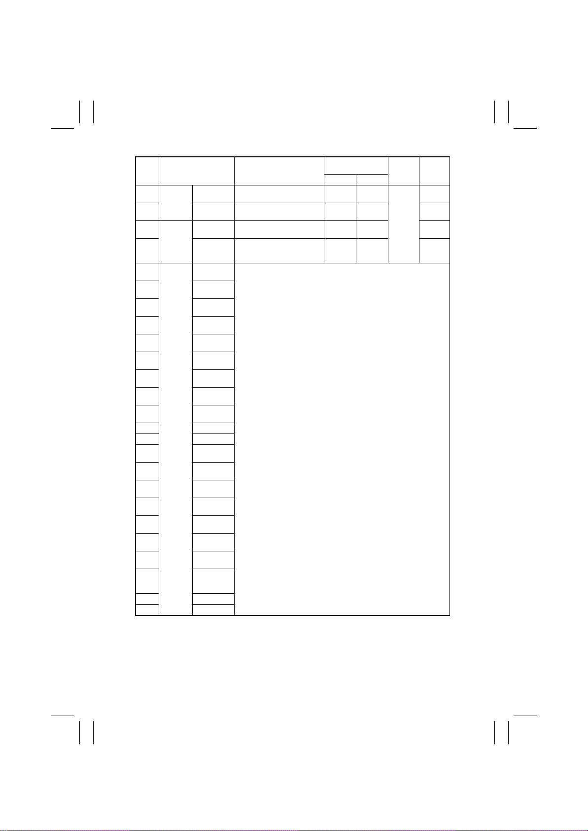
FrameMaker Ver.5.5E(PC) 8020/8031 TROUBLESHOOT ING
02.08.19
Operation Characteris-
Symbol Panel Display Part/Signal Name
PC29 Toner
Collect
PC18 Toner Box Set Waste Toner Bottle Set Sensor In position Out of
- Fusing
PC7 Fuser Roller
PC1 Single
Finisher
PC19 Exit
PC3 Exit
PC4 Transport
PC2 Transport
PC6 Full
PC20 Full
PC7 Full
PC5 Empty
PWB-D Surface (Elev.)
PC8 Empty (Elev.)
PC9 Home
PC14 Home
PC12 Home
PC13 Home
- Home
- Empty St. 1
-Self
S2
S3
PC10 Home (Shift)
PC11 Shift Speed
Waste Toner Waste Toner Full Detecting Sen-
Unit
Separation
Staple
(Non-sort 1)
(Non-sort 3)
(Finisher)
Upper
Lower
(Non-sort 1)
(Non-sort 3)
(Elev. Tray)
(Finisher)
(CD-Align)
(Stap. Unit)
(store roller)
(Exit roller)
(Stapler 1)
Needle
Priming S1
Elevate Tray
Raised/Low-
sor
Set Fusing Unit In position Out of
Fusing Pressure Posi tion Sensor Pressed State
Exit
ered
See the FS-135 service manual
tics/Panel Display
10
Unblocked Blocked IO Bo ard
position
position
other than
pressed
Input
Board
(PWB-IO)
CN/PJ
No.
PJ24IO-
1B
PJ24IO-
4B
PJ4IO-6
PJ4IO-3
T-8
Page 11
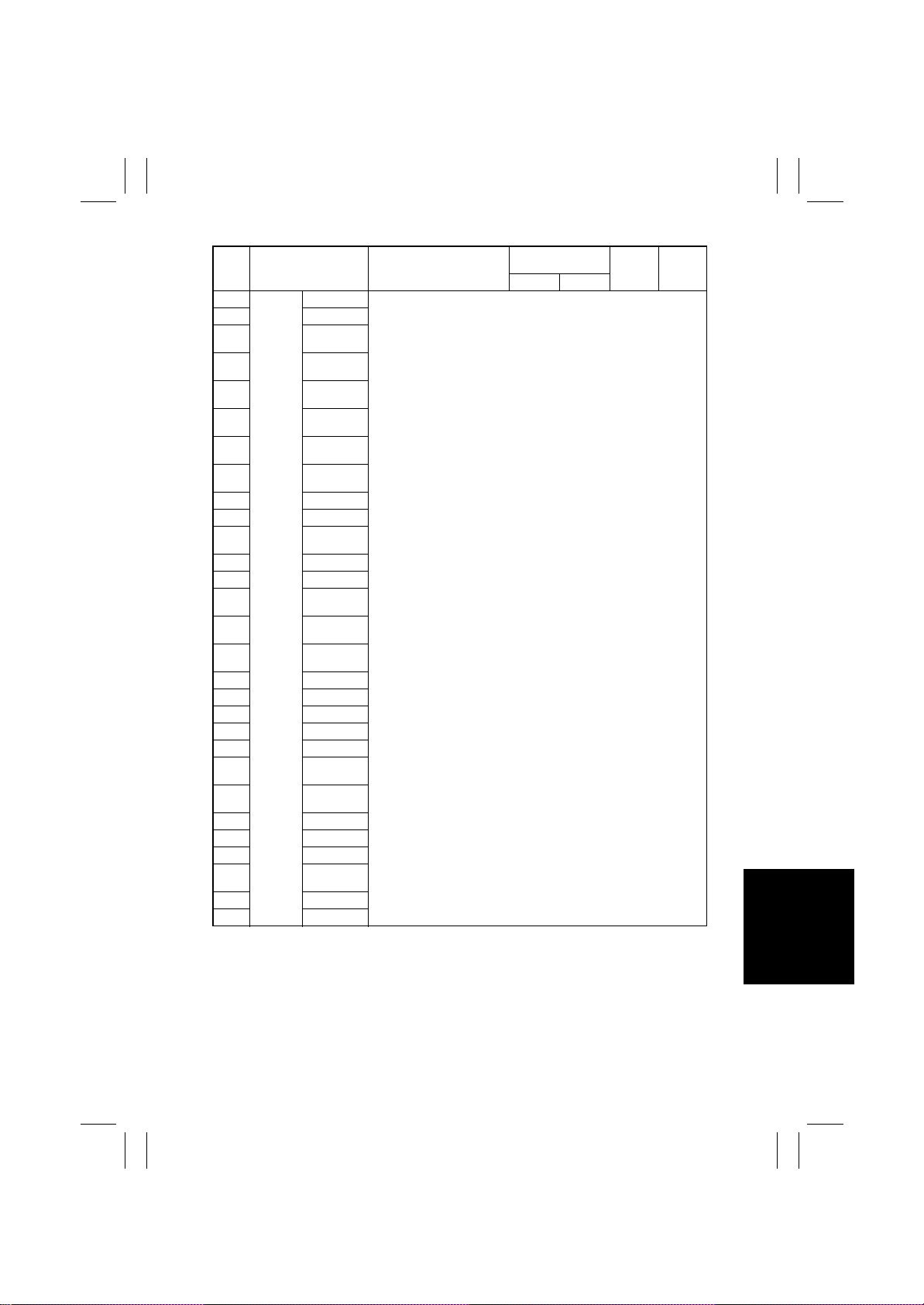
FrameMaker Ver.5.5E(PC) 8020/8031 TROUBLESHOOT ING
02.08.19
Symbol Panel Display Part/Signal Name
PI1 Center
Staple
PI2 Paddle Home
Finisher
PI3 Bundle Roller
PI4 Align Home
PI5 Align Home
PI6 Alignment
PI7 Exit Belt
PI10 Crease
PI13 Crease Tray
PI11 Crease Home
PI12 Crease Roller
PI14 Crease Clock
PI8 Paper
PI9 Paper
PI15 Raised
PI16 Lowered Posi-
PI17 Clock
- Middle
PI18 Slide Home
PI19 Stapler Home
PI20 Needle
- Stapler
MS3 Stapler Safety
PI21 Self Prime
PI22 Front Door
PI23 Upper Door
MS1 Front Door
- Rev. Remain
MS2 Joint SW
Entrance
Home
(Front)
(Back)
Tray
Home
Position
Home
Surface
Position
tion
Connect
SW
SW
See the FS-231 service manual
Operation Characteris-
tics/Panel Display
10
Input
Board
CN/PJ
No.
T-9
Page 12
FrameMaker Ver.5.5E(PC) 8020/8031 TROUBLESHOOT ING
02.08.19
Symbol Panel Display Part/Signal Name
- Center
Staple
Finisher
- Punch Reg-
- Punch Reg-
- Punch Reg-
- Punch Wastes
- Punch Tim-
PI3P Punch Motor
PI1P Punch Home
PI2P Punch Reg-
PC4 Transport
PC201 IR Home
SW201 Org.
Detect
PC202 15 Degree
Sensor
PC203 Org. Detect
PC204 Org. Detect
PC204 Org. Detect
PC206 Org. Detect
PC206 Org. Detect
PC205 Org. Detect
PC205 Org. Detect
PC207 Org. Detect
Punch Reg-
ist. S1
ist. S2
ist. S3
ist. S4
See the FS-231 service manual
ing
Clock
ist. Home
Doors
Sensor
Org. Cover Size Reset Switch Lowered Raised PJ11C-9
Sensor
Sensor 1
Sensor 2
Sensor 3
Sensor 4
Sensor 5
Sensor 6
Sensor 7
Sensor 8
Scanner Home Sensor At home Out of
Original Cover Detecting Sensor Less than
Original Size
Detecting Sensor FD1
Original Size
Detecting Sensor FD2
Original Size
Detecting Sensor FD2
Original Size
Detecting Sensor FD3
Original Size
Detecting Sensor FD3
Original Size
Detecting Sensor CD1
Original Size
Detecting Sensor CD1
Original Size
Detecting Sensor CD2
Operation Characteris-
tics/Panel Display
10
home
15° or
15°
Original
loaded,
not
mounted
Original
loaded,
not
mounted
Original
loaded,
not
mounted
Original
loaded,
not
mounted
Original
loaded,
not
mounted
Original
loaded,
not
mounted
Original
loaded,
not
mounted
Original
loaded,
not
mounted
more
Original
not loaded
Original
not loaded
Original
not loaded
Original
not loaded
Original
not loaded
Original
not loaded
Original
not loaded
Original
not loaded
Input
Board
Image
Process-
ing Board
(PWB-C)
CN/PJ
No.
PJ11C-7
PJ8C-
12B
PJ8C-1A
PJ8C-9A
PJ8C-9A
PJ7C-5
PJ7C-5
PJ11C-5
PJ11C-5
PJ10C-5
T-10
Page 13
FrameMaker Ver.5.5E(PC) 8020/8031 TROUBLESHOOT ING
02.08.19
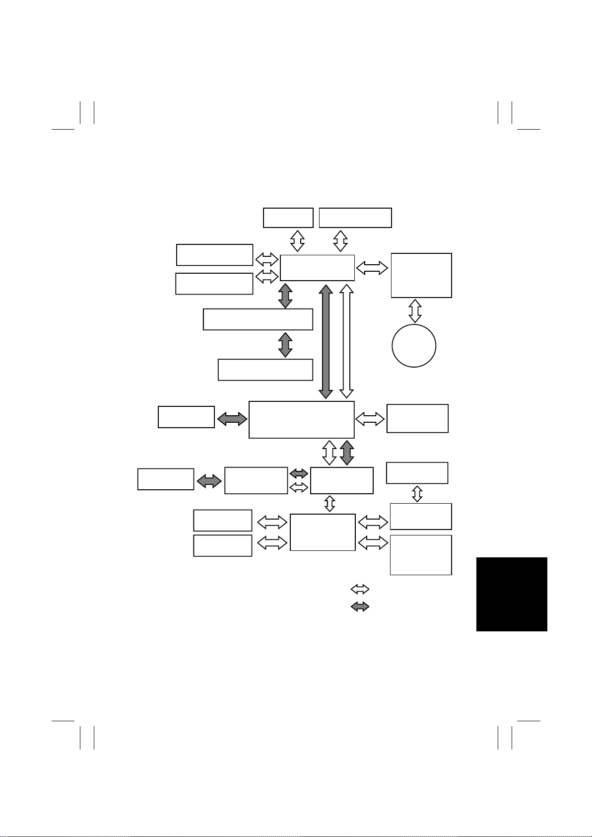
1-3. System Control Block Diagram
• Understanding the system control block diagram will help make easier the troubleshooting procedures for paper misfeeds, malfunctions, and image problems.
IR
Engine
LPH Assy
DC Power Supply
3 PU201
Scanner Assy
Printer
Controller
DF-332
Image Processing
Board PWB-C
Image Processing Interface
Board PWB-B
CCD Sensor Board
PWB-A
Image Control Board
PWB-F
LED Drive Board
PWB-LED
Control Panel
UN201
PIC Board
PWB-PIC
Scanner Motor
Drive Board
PWB-IC
Scanner
Motor
M201
Option Interface
Board PWB-G
Paper Source
Option
4025T001AC
AD-231
Output
Option
T-11
IO Board
PWB-IO
Control Board
PWB-A
DC Power
Supply 1
PU1
Control System Line
Image Bus Line
Page 14
FrameMaker Ver.5.5E(PC) 8020/8031 TROUBLESHOOT ING
02.08.19
2. PAPER MISFEED
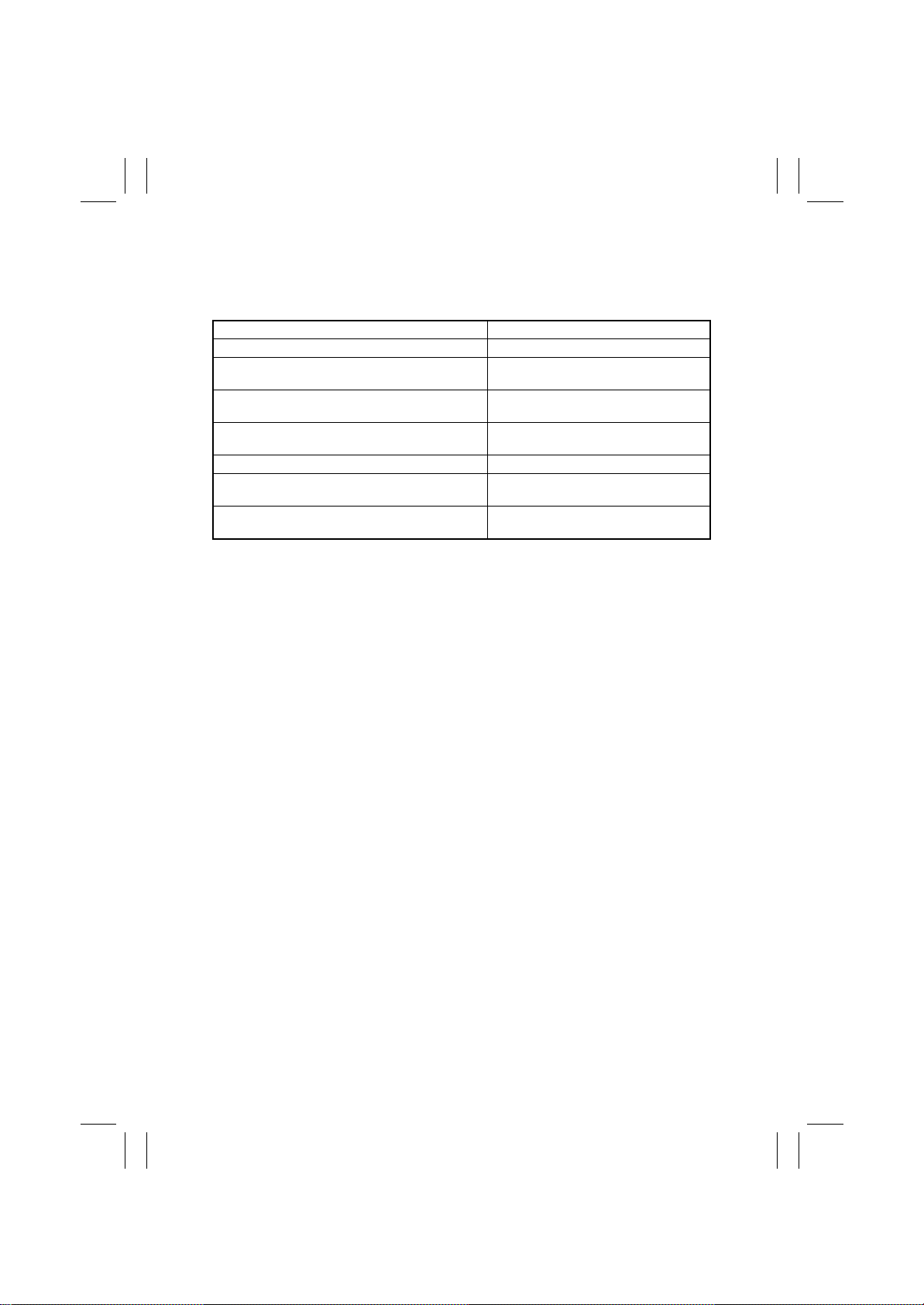
2-1. Initial Check Items
• When a paper misfeed occurs, first make checks of the following initial check items.
Check Item Action
Does paper meet product specifications? Change paper.
Is paper curled, wavy, or damp.
Is a foreign object present along the paper path, or is
the paper path deformed or worn?
Are the Paper Separator Fingers dirty, deformed, or
worn?
Are rolls/rollers dirty, deformed, or worn? Clean or change the defective roll/roller.
Are the Edge Guide and Trailing Edge Stop at correct
position to accommodate paper?
Are actuators found operational as checked for correct
operation?
Change paper.
Instruct user in correct paper storage.
Clean or change the paper path.
Clean or change the defective Paper Sepa-
rator Fi nger.
Set as necessary.
Correct or change the defective actuator.
T-12
Page 15
FrameMaker Ver.5.5E(PC) 8020/8031 TROUBLESHOOT ING
02.08.19
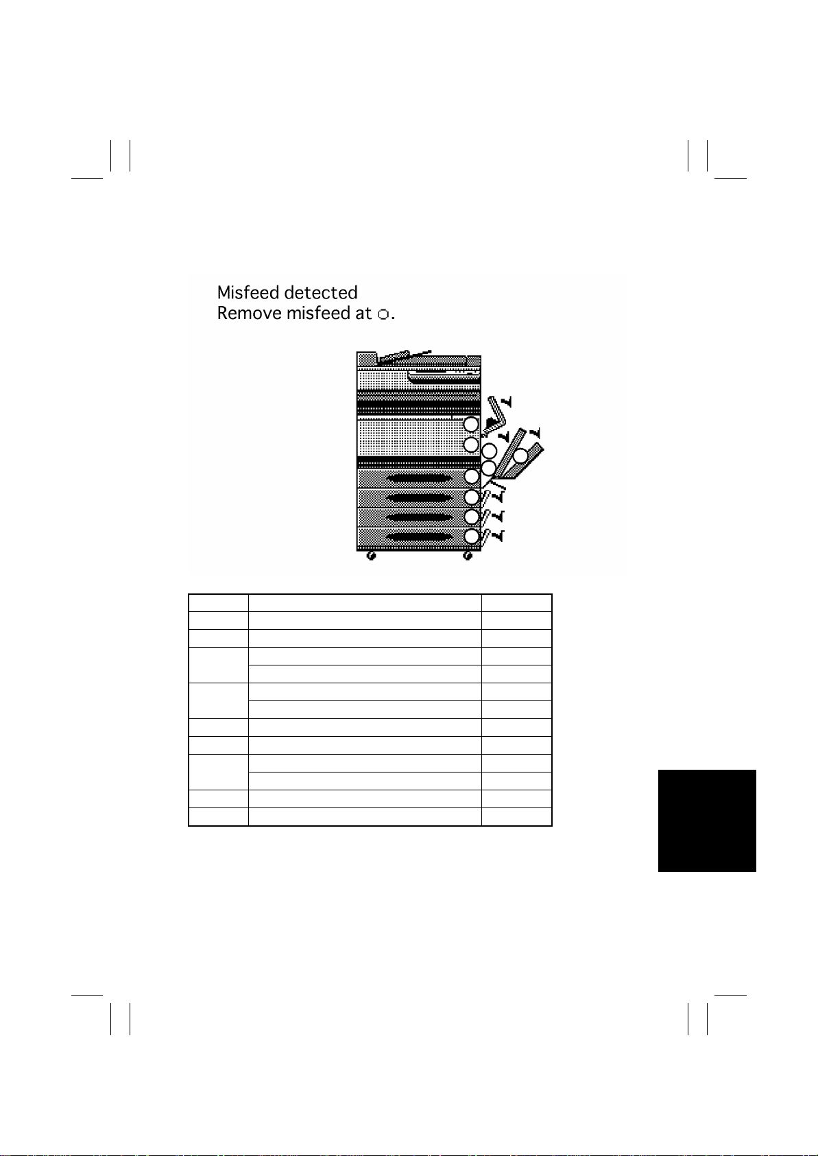
2-2. Misfeed Display
• When a paper misfeed occurs, the misfeed message, misfeed location, and paper location are displayed on the Touch Panel of the copier.
I
H
E
F
G
A
B
C
D
Display Misfeed Location Action
A1st Drawer take-up
B 2nd Drawer take-up
3rd Drawer take-up
C
LCT take-up
4th Drawer take-up
D
LCT Lift 2 to 1 paper transport
E Manual Bypass take-up
F Duplex Unit transport
Vertical Transport
G
Duplex Unit take-up
H 2nd Image Transfer
I Fusing/Exit
<Misfeed Display Resetting Procedure>
• Open the corresponding door, clear the sheet of paper misfeed, and close the door.
☞
☞
☞
☞
☞
☞
☞
☞
☞
☞
☞
☞
T-1 6
T-1 7
T-1 8
T-1 9
T-2 0
T-2 1
T-2 2
T-2 7
T-2 3
T-2 6
T-2 8
T-2 9
T-13
Page 16
FrameMaker Ver.5.5E(PC) 8020/8031 TROUBLESHOOT ING
02.08.19
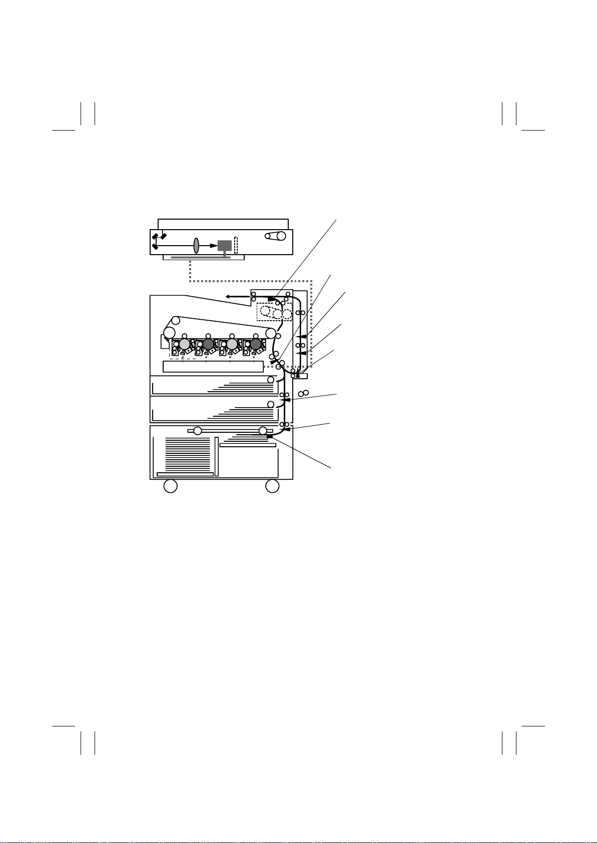
2-3. Misfeed Detecting Sensor Layout
• System Mounted with AD-231 and DB-432
Exit Sensor PC10
Synchronizing Roller Sensor PC14
Duplex Unit Transport
Sensor 1 PI1
Duplex Unit Transport
Sensor 2 PC1
Manual Feed Paper Take-Up
Sensor PC15
4025T003AA
2nd Drawer Paper Take-Up
Sensor PC101
LCT Registration Sensor
RSEN
LCT Paper Take-Up Sensor
PPS0
T-14
Page 17
FrameMaker Ver.5.5E(PC) 8020/8031 TROUBLESHOOT ING
02.08.19
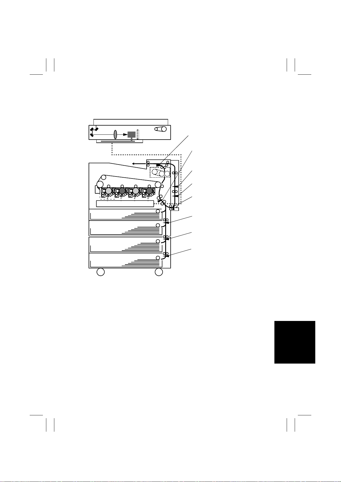
• System Mounted with AD-231 and PF-232
Exit Sensor PC10
Synchronizing Roller Sensor PC14
Duplex Unit Transport
Sensor 1 PI1
Duplex Unit Transport
Sensor 2 PC1
Manual Feed Paper Take-Up
Sensor PC15
2nd Drawer Paper Take-Up
Sensor PC101
4025T004AA
3rd Drawer Paper Take-Up
Sensor PC1
4th Drawer Paper Take-Up
Sensor PC1
T-15
Page 18
FrameMaker Ver.5.5E(PC) 8020/8031 TROUBLESHOOT ING
02.08.19
2-4. Misfeed Detection Timing/Troubleshooting Procedures
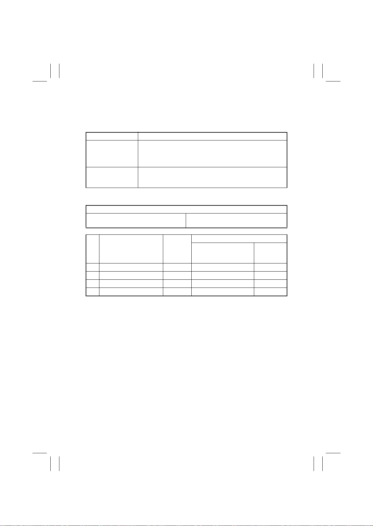
(1) 1st Drawer Paper Take-Up Misfeed
<Detection Timing>
Type Description
The leading edge of the paper does not block the Synchronizing
Paper take-up fail ure
detection
1st Drawer size error
detection
<Action>
Synchronizing Roller Sensor (PC14)
1st Drawer Paper Take-Up Clutch (CL1)
Step Action Ref. Page
1 Initial check items T-12 ——
2 PC14 I/O check T-4 to T-10 — 2-I
3 CL1 operation check T-2 PWB-IO PJ10IO-8 (ON) 8-A
4 Change PWB-IO. —— —
Roller Sensor (PC14) even after the lapse of a given period of time
after the 1st Drawer Paper Take-Up Clutch (CL1) has been ener-
gized.
The Synchronizing Roller Sensor (PC14) is not unblocked even
after the lapse of a given period of time after it has been blocked
by the paper.
Relevant Electrical Parts
IO Board (PWB-IO)
WIRING DIAGRAM
Control Signal
Location
(Electrical
Component)
T-16
Page 19
FrameMaker Ver.5.5E(PC) 8020/8031 TROUBLESHOOT ING
02.08.19
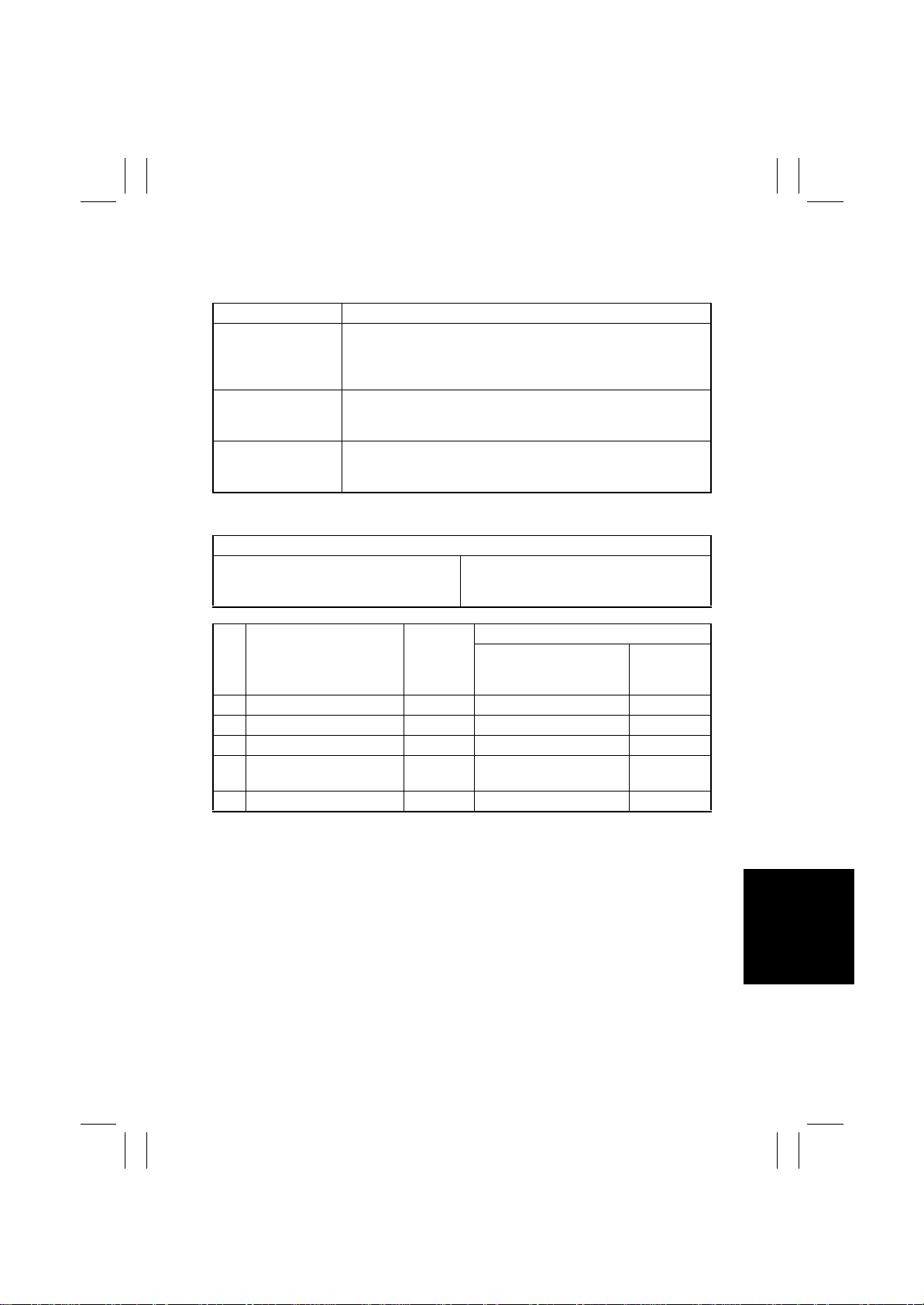
(2) 2nd Drawer Paper Take-Up Misfeed
<Detection Timing>
Type Description
Paper take-up fail ure
detection
2nd Drawer size error
detection
Detection of paper left
in 2nd Drawer
<Action>
2nd Drawer Take-Up Sensor (PC10 1)
2nd Drawer Take-Up Clutch (CL101)
2nd Drawer Take-Up Motor (M101)
The leading edge of the paper does not block the 2nd Drawer
Paper Tak e-Up Sensor (PC101) even after the lapse of a given
period of time after the 2nd Drawer Paper Take-Up Clutch (CL101)
has been energized.
The 2nd Drawer Paper Take-Up Sensor (PC101) is not unblocked
even after the lapse of a given period of time after it has been
blocked by the paper.
The 2nd Drawer Paper Take-Up Sensor (PC101) is blocked when
the Power Switch is turned ON, a door or cover is opened and
closed, or a misfeed or malfunction is reset.
Relevant Electrical Parts
2nd Drawer Control Board (PWB-A)
WIRING DIAGRAM
Step Action Ref. Page
1 Initial check items T-12 ——
2 PC101 I/O check T-4 to T-10 — 6-H
3 CL101 operation check T-2 PWB-A PJ3A-14B (ON) 5-I
4 M101 operation check T-3
5 Change PWB-A. —— —
Control Signal
PWB-A PJ5A-1 to 4
(Pulse Output)
Location
(Electrical
Component)
6-G
T-17
Page 20
FrameMaker Ver.5.5E(PC) 8020/8031 TROUBLESHOOT ING
02.08.19
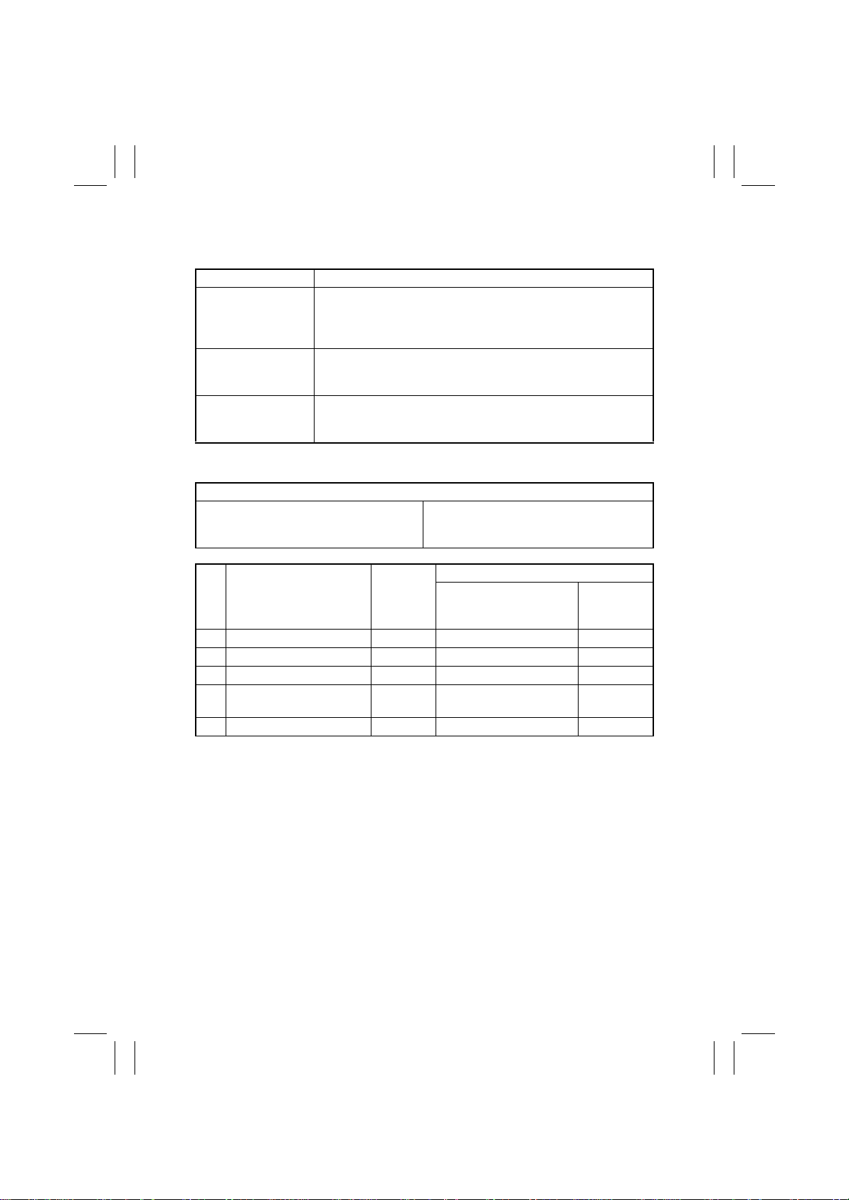
(3) 3rd Drawer Paper Take-Up Misfeed (PF-232)
<Detection Timing>
Type Description
Paper take-up fail ure
detection
3rd Drawer size error
detection
Detection of paper left
in 3rd Drawer
<Action>
3rd Drawer Ta ke-Up Sensor (PC1)
3rd Drawer Ta ke-Up Clutch (CL1)
3rd Drawer Ta ke-Up Motor (M1)
The leading edge of the paper does not block the 3rd Drawer
Paper Tak e-Up Sensor (PC1) even after the lapse of a given period
of time after the 3rd Drawer Paper Take-Up Clutch (CL1) has been
energized.
The 3rd Drawer Paper Take-Up Sensor (PC1) is not unblocked
even after the lapse of a given period of time after it has been
blocked by the paper.
The 3rd Drawer Paper Take-Up Sensor (PC1) is blocked when the
Power Switch is turned ON, a door or cover is opened and closed,
or a misfeed or malfunction is reset.
Relevant Electrical Parts
3rd Drawer Control Board (PWB-A)
WIRING DIAGRAM
Step Action Ref. Page
1 Initial check items T-12 ——
2 PC1 I/O check T-4 to T-10 — 2-D
3 CL1 operation check T-2 PWB-A PJ3A-14B (ON) 2-I
4 M1 operation check T-3
5 Change PWB-A. —— —
Control Signal
PWB-A PJ5A-1 to 4
(Pulse Output)
Location
(Electrical
Component)
2-A
T-18
Page 21
FrameMaker Ver.5.5E(PC) 8020/8031 TROUBLESHOOT ING
02.08.19
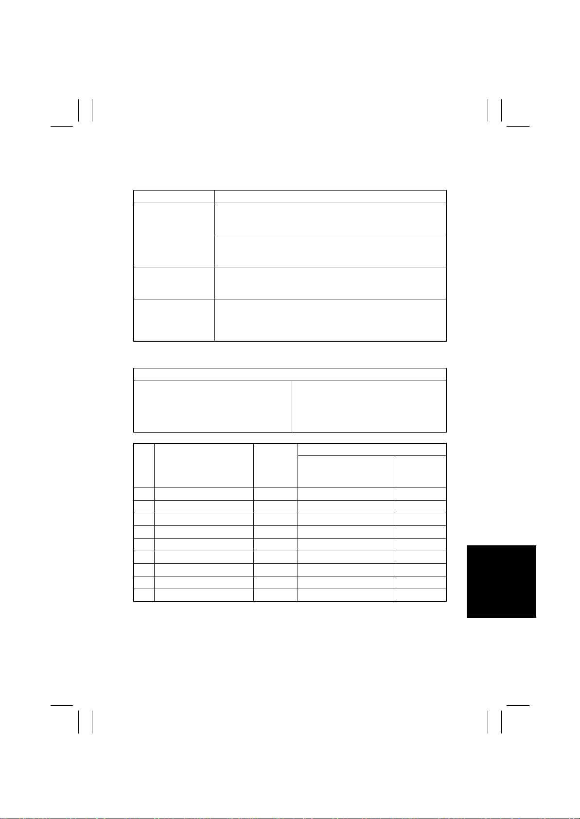
(4) LCT Paper Take-Up Misfeed (DB-432)
<Detection Timing>
Type Description
The LCT Exit signal does not turn ON even after the lapse of a
given period of time after an LCT paper take-up request has been
LCT paper take-up
failure detection
LCT size error detection
Detection of paper left
in LCT
<Action>
LCT Paper Take-Up Sensor (PP S0)
LCT Registration Sensor (RSEN)
2nd Drawer Paper Take-Up Sensor (PC101)
LCT Paper Take-Up Clutch1 (P1CL)
LCT Paper Take-Up Clutch2 (P2CL)
issued.
The LCT Registration Sensor (RSEN) is not blocked even after the
lapse of a given period of time after an LCT paper take-up request
has been issued.
The 2nd Drawer Paper Take-Up Sensor (PC101) is not blocked
even after the lapse of a given period of time after it has been
blocked by the paper.
The LCT Registration Sensor (RSEN) or 2nd Drawer Paper Take-
Up Sensor (PC101) is blocked when the Power Switch is turned
ON, a door or cover is opened and closed, or a misfeed or mal-
function is reset.
Relevant Electrical Parts
LCT Separator Clutch (BCL)
LCT Registration Clutch (RCL)
LCT Control Board (PWB-A)
WIRING DIAGRAM
Step Action Ref. Page
1 Initial check items T-12 ——
2 PPS0 I/O check T-4 to T-10 — 7-D
3 RSEN I/O check T-4 to T-10 — 7-E
4 PC101 I/O check T-4 to T-10 — 6-H (Copier)
5 P1CL operation check T-2 PWB-A CN7A-8 (ON) 7-B
6 P2CL operation check T-2 PWB-A CN7A-6 (ON) 7-B
7 BCL operation check T-2 PWB-A CN7A-2 (ON) 7-C
8 RCL operation check T-2 PWB-A CN7A-4 (ON) 7-C
9 Change PWB-A. —— —
Control Signal
Location
(Electrical
Component)
T-19
Page 22
FrameMaker Ver.5.5E(PC) 8020/8031 TROUBLESHOOT ING
02.08.19
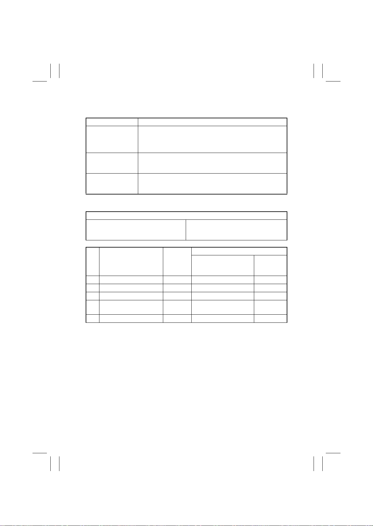
(5) 4th Drawer Paper Take-Up Misfeed (PF-232)
<Detection Timing>
Type Description
Paper take-up fail ure
detection
4th Drawer size error
detection
Detection of paper left
in 4th Drawer
<Action>
4th Drawer Take-Up Sensor (PC1)
4th Drawer Take-Up Clutch (CL1)
4th Drawer Take-Up Motor (M1)
The leading edge of the paper does not block the 4th Drawer
Paper Tak e-Up Sensor (PC1) even after the lapse of a given period
of time after the 4th Drawer Paper Tak e-Up Clutch (CL1) has been
energized.
The 4th Drawer Paper Take-Up Sensor (PC1) is not unblocked
even after the lapse of a given period of time after it has been
blocked by the paper.
The 4th Drawer Paper Take-Up Sensor (PC1) is blocked when the
Power Switch is turned ON, a door or cover is opened and closed,
or a misfeed or malfunction is reset.
Relevant Electrical Parts
4th Drawer Control Board (PWB-A)
WIRING DIAGRAM
Step Action Ref. Page
1 Initial check items T-12 ——
2 PC1 I/O check T-4 to T-10 — 2-D
3 CL1 operation check T-2 PWB-A PJ3A-14B (ON) 2-I
4 M1 operation check T-3
5 Change PWB-A. —— —
Control Signal
PWB-A PJ5A-1 to 4
(Pulse Output)
Location
(Electrical
Component)
2-A
T-20
Page 23
FrameMaker Ver.5.5E(PC) 8020/8031 TROUBLESHOOT ING
02.08.19
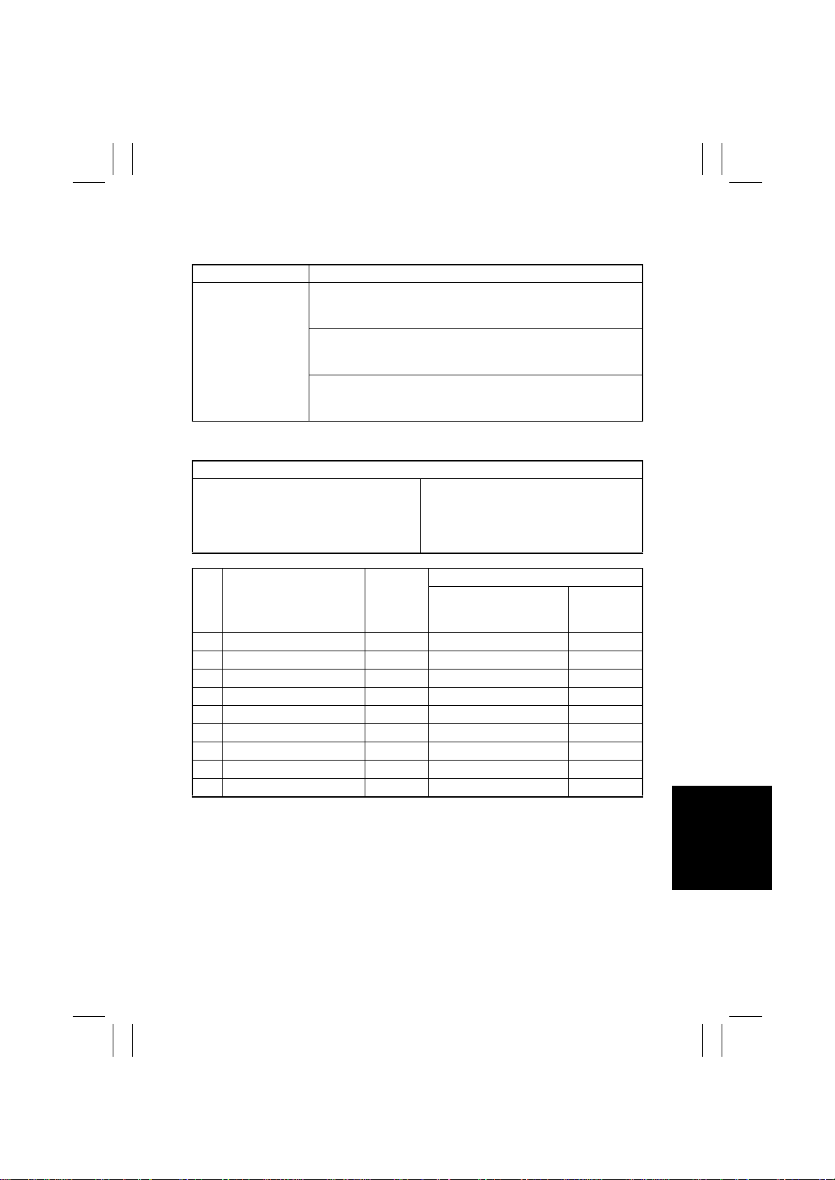
(6) LCT Lift 2 to 1 paper transport Misfeed (DB-432)
<Detection Timing>
Type Description
The LCT Paper Take-Up Sensor (PPS0) is not blocked even after
the lapse of a given period of time after an LCT paper take-up
request has been issued.
Lift 2 to 1 misfeed
detection
<Action>
LCT Paper Take-Up Sensor (PP S0)
Paper Standby Position Sensor (S1)
LCT Registration Sensor (RSEN)
LCT Paper Take-Up Clutch1 (P1CL)
LCT Paper Take-Up Clutch2 (P2CL)
The LCT Registration Sensor (RSEN) is not blocked even after the
lapse of a given period of time after an LCT paper take-up request
has been issued.
The Paper Standby Position Sensor (S1) is not block ed even after
the lapse of a given period of time after an LCT paper take-up
request has been issued.
Relevant Electrical Parts
LCT Separator Clutch (BCL)
LCT Registration Clutch (RCL)
LCT Control Board (PWB-A)
WIRING DIAGRAM
Step Action Ref. Page
1 Initial check items T-12 ——
2 PPS0 I/O check T-4 to T-10 — 7-D
3 RSEN I/O check T-4 to T-10 — 7-E
4 S1 I/O check T-4 to T-10 — 7-G
5 P1CL operation check T-2 PWB-A CN7A-8 (ON) 7-B
6 P2CL operation check T-2 PWB-A CN7A-6 (ON) 7-B
7 BCL operation check T-2 PWB-A CN7A-2 (ON) 7-C
8 RCL operation check T-2 PWB-A CN7A-4 (ON) 7-C
9 Change PWB-A. —— —
Control Signal
Location
(Electrical
Component)
T-21
Page 24
FrameMaker Ver.5.5E(PC) 8020/8031 TROUBLESHOOT ING
02.08.19
(7) Manual Bypass Take-Up Misfeed
<Detection Timing>
Type Description
Manual bypass paper
take-up failure detection
Manual bypass size
error detection
Detection of paper left
in Manual Bypass
Table
<Action>
Manual Feed Paper Take-Up Sensor (PC15)
Synchronizing Roller Sensor (PC14)
Manual Feed Paper Take-Up Clutch (CL3)
The Synchronizing Roller Sensor (PC14) is not blocked even after
the lapse of a given period of time after the Manual Feed Paper
Take-Up Sensor (PC15) has been blocked by the paper.
The Synchronizing Roller Sensor (PC14) is not unblocked even
after the lapse of a given period of time after it has been blocked
by the paper.
The Manual Feed Paper Take-Up Sensor (PC15) is blocked when
the Power Switch is turned ON, a door or cover is opened and
closed, or a misfeed or malfunction is reset.
Relevant Electrical Parts
IO Board (PWB-IO)
WIRING DIAGRAM
Step Action Ref. Page
1 Initial check items T-12 ——
2 PC15 I/O check T-4 to T-10 — 1-B
3 PC14 I/O check T-4 to T-10 — 2-I
4 CL3 operation check T-2 PWB-IO PJ10IO-1 (ON) 1-A
5 Change PWB-IO. —— —
Control Signal
Location
(Electrical
Component)
T-22
Page 25
FrameMaker Ver.5.5E(PC) 8020/8031 TROUBLESHOOT ING
02.08.19
(8) Vertical Transport Misfeed
<Detection Timing>
Type Description
(Copier)
The Synchronizing Roller Sensor (PC14) is not blocked even after
the lapse of a given period of time after the 2nd Drawer Paper
Take-Up Sensor (PC101) has been blocked by the paper .
(PF-232)
The 2nd Drawer Paper Take-Up Sensor (PC101) is not blocked
even after the lapse of a given period of time after the 3rd Drawer
Vertical Transport mis-
feed detection
Paper Tak e-Up Sensor (PC1) has been blocked by the paper.
(PF-232)
The 3rd Drawer Paper Take-Up Sensor (PC1) is not blocked even
after the lapse of a given period of time after the 4th Drawer Paper
Take-Up Sensor (PC1) has been blocked by the paper.
(DB-432)
The 2nd Drawer Paper Take-Up Sensor (PC101) is not blocked
even after the lapse of a given period of time after an LCT paper
take-up request has been issued.
<Action>
Copier
Relevant Electrical Parts
2nd Drawer Paper Take-Up Sensor (PC101)
Synchronizing Roller Sensor (PC14)
2nd Drawer Paper Take-Up Clutch (CL101)
2nd Drawer Paper Take-Up Motor (M101)
Step Action Ref. Page
1 Initial check items T-12 ——
2 PC101 I/O check T-4 to T-10 — 6-H
3 PC14 I/O check T-4 to T-10 — 2-I
4 CL101 operation check T- 2 PWB-A PJ13A-14B (ON) 5-I
5 M101 operation check T-3
6 Change PWB-A. —— —
2nd Drawer Control Board (PWB-A)
WIRING DIAGRAM
Control Signal
PWB-A PJ5A-1 to 4
(Pulse Output)
Location
(Electrical
Component)
6-G
T-23
Page 26
FrameMaker Ver.5.5E(PC) 8020/8031 TROUBLESHOOT ING
02.08.19
PF-232
Relevant Electrical Parts
2nd Drawer Paper Take-Up Sensor (PC101)
3rd Drawer Paper Take-Up Sensor (PC1)
4th Drawer Paper Take-Up Sensor (PC1)
3rd Drawer Paper Take-Up Clutch (CL1)
4th Drawer Paper Take-Up Clutch (CL1)
Step Action Ref. Page
1 Initial check items T-12 ——
2 PC101 I/O check T-4 to T-10 — 6-H (Copier)
3 PC1(3rd Drawer) I/O check T-4 to T-10 — 2-D
4 PC1(4th Drawer) I/O check T-4 to T-10 — 2-D
CL1(3rd Drawer)
5
operation check
CL1(4th Drawer)
6
operation check
M1(3rd Drawer)
7
operation check
M1(4th Drawer)
8
operation check
Change PWB-A
9
(3rd Drawer).
Change PWB-A
10
(4th Drawer).
3rd Drawer Paper Take-Up Motor (M1)
4th Drawer Paper Take-Up Motor (M1)
3rd Drawer Control Board (PWB-A)
4th Drawer Control Board (PWB-A)
WIRING DIAGRAM
Control Signal
T-2 PWB-A PJ3A-14B (ON) 2-I
T-2 PWB-A PJ3A-14B (ON) 2-I
T-3
T-3
—— —
—— —
PWB-A PJ5A-1 to 4
(Pulse Output)
PWB-A PJ5A-1 to 4
(Pulse Output)
Location
(Electrical
Component)
2-A
2-A
T-24
Page 27
FrameMaker Ver.5.5E(PC) 8020/8031 TROUBLESHOOT ING
02.08.19
DB-432
Relevant Electrical Parts
LCT Paper Take-Up Sensor (PP S0)
LCT Registration Sensor (RSEN)
2nd Drawer Paper Take-Up Sensor (PC101)
LCT Paper Take-Up Clutch1 (P1CL)
LCT Paper Take-Up Clutch2 (P2CL)
Step Action Ref. Page
1 Initial check items T-12 ——
2 PC101 I/O check T-4 to T-10 — 6-H (Copier)
3 PPS0 I/O check T-4 to T-10 — 7-D
4 RSEN I/O check T-4 to T-10 — 7-E
5 P1CL operation check T-2 PWB-A CN7A-8 (ON) 7-B
6 P2CL operation check T-2 PWB-A CN7A-6 (ON) 7-B
7 BCL operation check T-2 PWB-A CN7A-2 (ON) 7-C
8 RCL operation check T-2 PWB-A CN7A-4 (ON) 7-C
9 Change PWB-A. —— —
LCT Separator Clutch (BCL)
LCT Registration Clutch (RCL)
LCT Control Board (PWB-A)
WIRING DIAGRAM
Control Signal
Location
(Electrical
Component)
T-25
Page 28
FrameMaker Ver.5.5E(PC) 8020/8031 TROUBLESHOOT ING
02.08.19
(9) Duplex Paper Take-Up Misfeed (AD-231)
<Detection Timing>
Type Description
Duplex paper take-up
misfeed detection
<Action>
Synchronizing Roller Sensor (PC14)
Duplex Unit Motor (M2)
Step Action Ref. Page
1 Initial check items T-12 ——
3 PC14 I/O check T-4 to T-10 — 2- I (Copier)
4 M2 operation check T-3
5 Change PWB-A. —— —
6 Change PWB-IO. —— —
The Synchronizing Roller Sensor (PC14) is not blocked even after
the lapse of a given period of time after a Duplex paper take-up
sequence has been started.
Relevant Electrical Parts
Duplex Control Board (PWB-A)
IO Board (PWB-IO)
WIRING DIAGRAM
Control Signal
PWB-A PJ2A-1 to 4
(Pulse Output))
Location
(Electrical
Component)
2-H
T-26
Page 29
FrameMaker Ver.5.5E(PC) 8020/8031 TROUBLESHOOT ING
02.08.19
(10) Duplex Paper Transport Misfeed (AD-231)
<Detection Timing>
Type Description
The Manual Feed Paper Take-Up Sensor (PC15) is not blocked
even after the lapse of a given period of time after a Duplex paper
Duplex transport mis-
feed detection
Detection of paper left
in Duplex
<Action>
Manual Feed Paper Take-Up Sensor (PC15)
Duplex Unit Transport Sensor 1 (PI1)
Duplex Unit Transport Sensor 2 (PC1)
Switchback Motor (M1)
Duplex Unit Motor (M2)
take-up sequence has been started.
The Duplex Unit Transport Sensor 2 (PC1) is not blocked even
after the lapse of a given period of time after the Duplex Unit
Transport Sensor 1 (PI1) has been blocked by the paper.
The Duplex Unit Transport Sensor 1 (PI1) or Duplex Unit T r ansport
Sensor 2 (PC1) is blocked when the Power Switch is turned ON, a
door or cover is opened and closed, or a misfeed or malfunction is
reset.
Relevant Electrical Parts
Duplex Control Board (PWB-A)
IO Board (PWB-IO)
WIRING DIAGRAM
Step Action Ref. Page
1 Initial check items T-12 ——
2 PC15 I/O check T-4 to T-10 — 1-B (Copier)
3 PI1 I/O check T-4 to T-10 — 4-H
4 PC1 I/O check T-4 to T-10 — 2-C
5 M1 operation check T-3
6 M2 operation check T-3
7 Change PWB-A. —— —
8 Change PWB-IO. —— —
Control Signal
PWB-A PJ3A-1 to 4
(Pulse Output))
PWB-A PJ2A-1 to 4
(Pulse Output))
Location
(Electrical
Component)
7-D
2-H
T-27
Page 30
FrameMaker Ver.5.5E(PC) 8020/8031 TROUBLESHOOT ING
02.08.19
(11) 2nd Image Transfer Misfeed
<Detection Timing>
Type Description
The Synchronizing Roller Sensor (PC14) is not unblocked even
after the lapse of a given period of time after it has been blocked
2nd Image Transfer
misfeed detection
Detection of paper left
at 2nd Image Transfer
<Action>
Synchronizing Roller Sensor (PC14)
Exit Sensor (PC10)
OHP Detecting Sensor (PC19)
by the paper.
The Exit Sensor (PC10) is not blocked even after the lapse of a
given period of time after the Synchronizing Roller Sensor (PC14)
has been blocked by the paper.
The Synchronizing Roller Sensor (PC14) is blocked when the
Power Switch is turned ON, a door or cover is opened and closed,
or a misfeed or malfunction is reset.
The OHP Detecting Sensor (PC19) is blocked when the Power
Switch is turned ON, a door or cover is opened and closed, or a
misfeed or malfunction is reset.
Relevant Electrical Parts
IO Board (PWB-IO)
WIRING DIAGRAM
Step Action Ref. Page
1 Initial check items T-12 ——
2 PC14 I/O check T-4 to T-10 — 2-I
3 PC10 I/O check T-4 to T-10 — 8-F
4 PC19 I/O check T-4 to T-10 — 2-I
5 Change PWB-IO. —— —
Control Signal
Location
(Electrical
Component)
T-28
Page 31
FrameMaker Ver.5.5E(PC) 8020/8031 TROUBLESHOOT ING
02.08.19
(12) Fusing/Exit Misfeed
<Detection Timing>
Type Description
The Exit Sensor (PC10) is not unblocked even after the lapse of a
Fusing/Exit misfeed
detection
Detection of paper left
at Fusing/Exit
<Action>
Exit Sensor (PC10)
Duplex Unit Transport Sensor 1 (PI1)
Step Action Ref. Page
1 Initial check items T-12 ——
2 PC10 I/O check T-4 to T-10 — 8-F
3 PI1 I/O check T-4 to T-10 — 4-H (AD-231)
4 Change PWB-IO. —— —
given period of time after it has been blocked by the paper.
The Duplex Unit Tr ansport Sensor 1 (PI1) is not blocked e v en af ter
the lapse of a given period of time after the Exit Sensor (PC10)
has been unblocked by the paper during a switchback sequence.
The Exit Sensor (PC10) is blocked when the Power Switch is
turned ON, a door or cover is opened and closed, or a misfeed or
malfunction is reset.
Relevant Electrical Parts
IO Board (PWB-IO)
WIRING DIAGRAM
Control Signal
Location
(Electrical
Component)
T-29
Page 32
FrameMaker Ver.5.5E(PC) 8020/8031 TROUBLESHOOT ING
02.08.19
3. MALFUNCTIONS
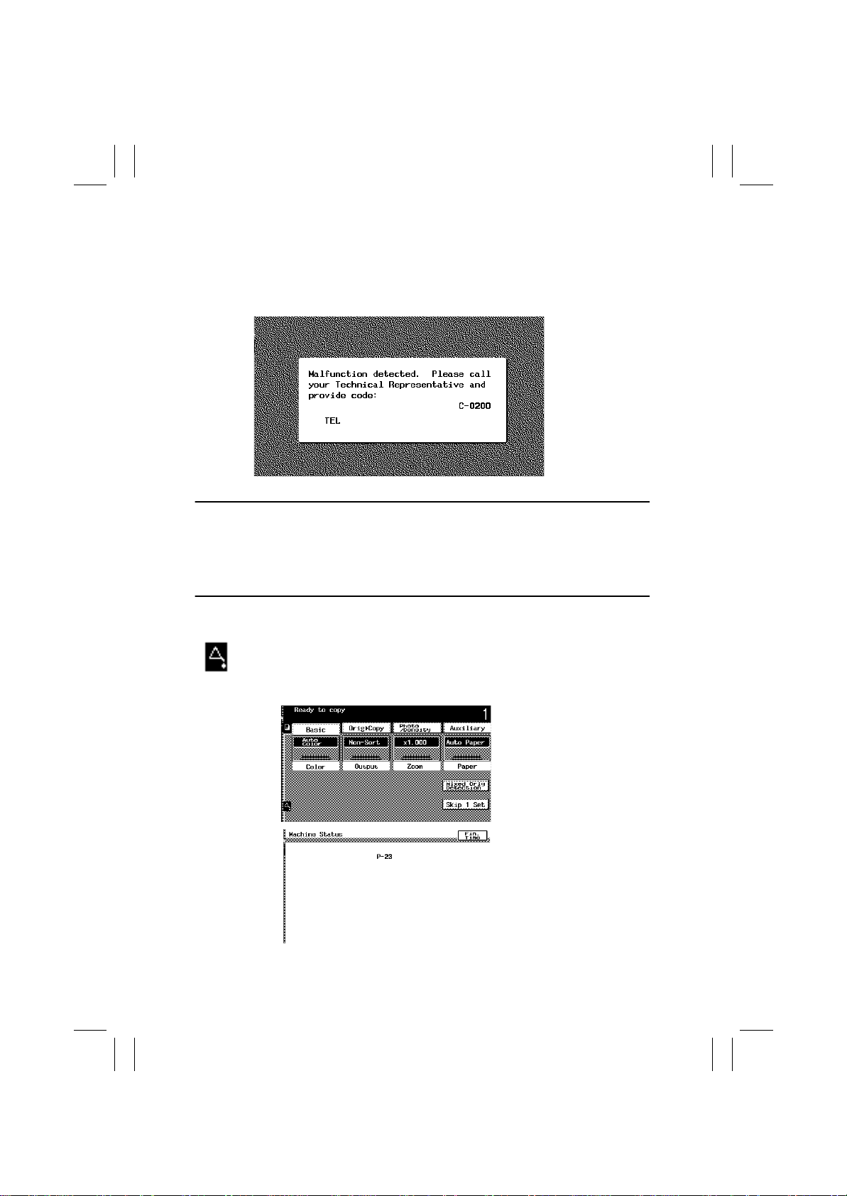
• The copier’s CPU performs a self-diagnostics function that, on detecting a malfunction,
gives the corresponding malfunction code and maintenance call mark on the Touch
Panel.
4025T565CA
Resetting a Malfunction
• Press the Trouble Reset Switch on the Tech. Rep . Setting Switches Board to reset the following malfunctions: scanner-related malfunctions, fusing-related malfunctions, e xposure
lamp-related malfunctions and C3FFF.
• For any other malfunctions, open and close the Front Door or turn OFF and ON the
Power Switch.
<Warning>
When a warning condition is detected, the maintenance call mark will be displayed
on the Touch Panel. Touching the maintenance call mark will display the corresponding warning code on the State Confirm screen.
k4025T566CA
4025T567CA
T-30
Page 33
FrameMaker Ver.5.5E(PC) 8020/8031 TROUBLESHOOT ING
02.08.19
3-1. Warning Detection Timing and Troubleshooting Procedure
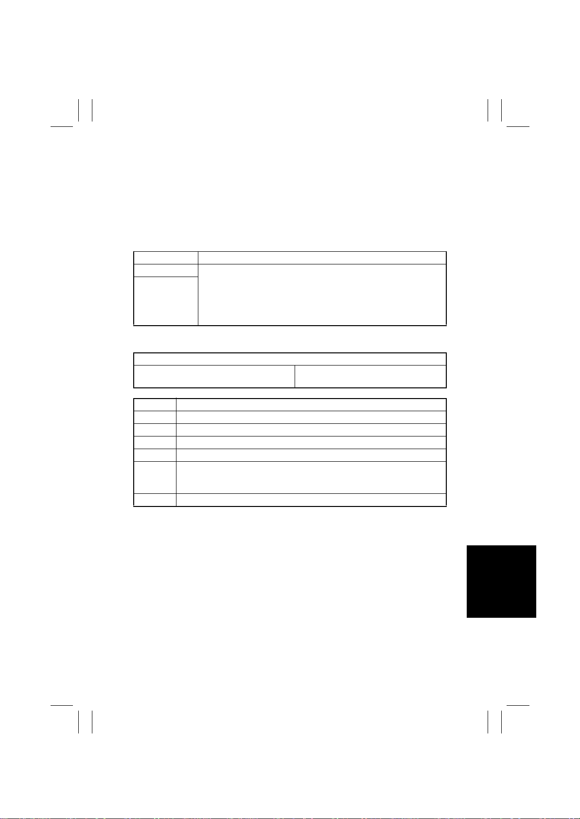
• If an image stabilization or IR-related fault occurs, the corresponding warning code
appears.
(1) P-5: AIDC Sensor (Front) failure
(2) P-28 AIDC Sensor (Back) failure
<Detection Timing>
Warning Code Description
P-5 • The output from the photoreceiver of the AIDC Sensor that takes a
P-28
<Action>
AIDC Sensor 1 (UN20)
AIDC Sensor 2 (UN21)
reading of a point of a bare surface on the Transfer Belt is 4.5 V or
more during an adjustment of the AIDC Sensor.
• The output from the photoreceiver of the AIDC Sensor that takes a
reading of a point in a toner pattern on the Transfer Belt is 1.0 V or
less after the adjustment has been completed.
Relevant Electrical Parts
IO Board (PWB-IO)
Image Transfer Belt Unit
Step Action
1 Wipe clean the surface of the Transfer Belt with a soft cloth, if it is dirty.
2 Change the Image Transfer Belt Unit if the Transfer Belt is damaged.
3 Reinstall or reconnect UN20 or UN21 if it is installed or connected improperly.
4 Clean UN20 or UN21 if it is dirty.
Open and close the Left Door, run an image stabilization sequence, and
5
select “State Confirm” -> “Level History 1” to check the AIDC value.
If the value is 1.0 V or less, change UN20 or UN21.
6 Change PWB-IO.
T-31
Page 34
FrameMaker Ver.5.5E(PC) 8020/8031 TROUBLESHOOT ING
02.08.19
(3) P-6: Cyan IU failure
(4) P-7: Magenta IU failure
(5) P-8: Yellow IU failure
(6) P-9: Black IU failure
<Detection Timing>
Warning Code Description
P-6
P-7
P-8
P-9
<Action>
IU (C)
IU (M)
IU (Y)
IU (Bk)
All density readings taken from the density pattern produced on the
Transfer Belt are 0.4 V (AIDC Sensor photoreceiver output) or less
during max. density adjustment (Vg/Vb adjustment).
Relevant Electrical Parts
Image Transfer Belt Unit
Step Action
→
Select “Image Adjust”
1
tive, readjust.
2 Check the drive transmission portion of the IU and correct as necessary.
3 Clean the AIDC Sensor window if dirty.
4 Clean the contact of the IU connector if dirty.
5 Change IU.
6 Change the Image Transfer Belt Unit.
“PRT Max Density” and, if the setting value is nega-
T-32
Page 35
FrameMaker Ver.5.5E(PC) 8020/8031 TROUBLESHOOT ING
02.08.19
(7) P-21: Color Shift Test Pattern failure
<Detection Timing>
Warning Code Description
• The number of points detected in the CD direction is more or less
P-21
<Action>
Image Transfer Belt Unit
Step Action
1 Wipe clean the surface of the Transfer Belt with a soft cloth, if it is dirty.
2 Change the Image Transfer Belt Unit if the Transfer Belt is damaged.
(8) P-22: Color Shift Adjust failure
than the specified value during CD registration correction.
• The number of points detected in the FD direction is more or less
than the specified value during FD registration correction.
Relevant Electrical Parts
<Detection Timing>
Warning Code Description
• The color shift amount is greater than the specified range during
P-22
<Action>
Regist Sensor 1 (UN20) Regist Sensor 2 (UN21)
Step Action
Check the LED retraction lever for locked position and, if there is any faulty
1
condition evident, slide out the IU and reinstall it in position.
2 Reinstall or reconnect UN20 or UN21 if it is installed or connected improperly.
Check the V ertical Transport Guide for installed position and correct as neces-
3
sary.
CD registration correction.
• The color shift amount is greater than the specified range during FD
registration correction.
• The skew correction amount is greater than the specified value.
Relevant Electrical Parts
T-33
Page 36
FrameMaker Ver.5.5E(PC) 8020/8031 TROUBLESHOOT ING
02.08.19
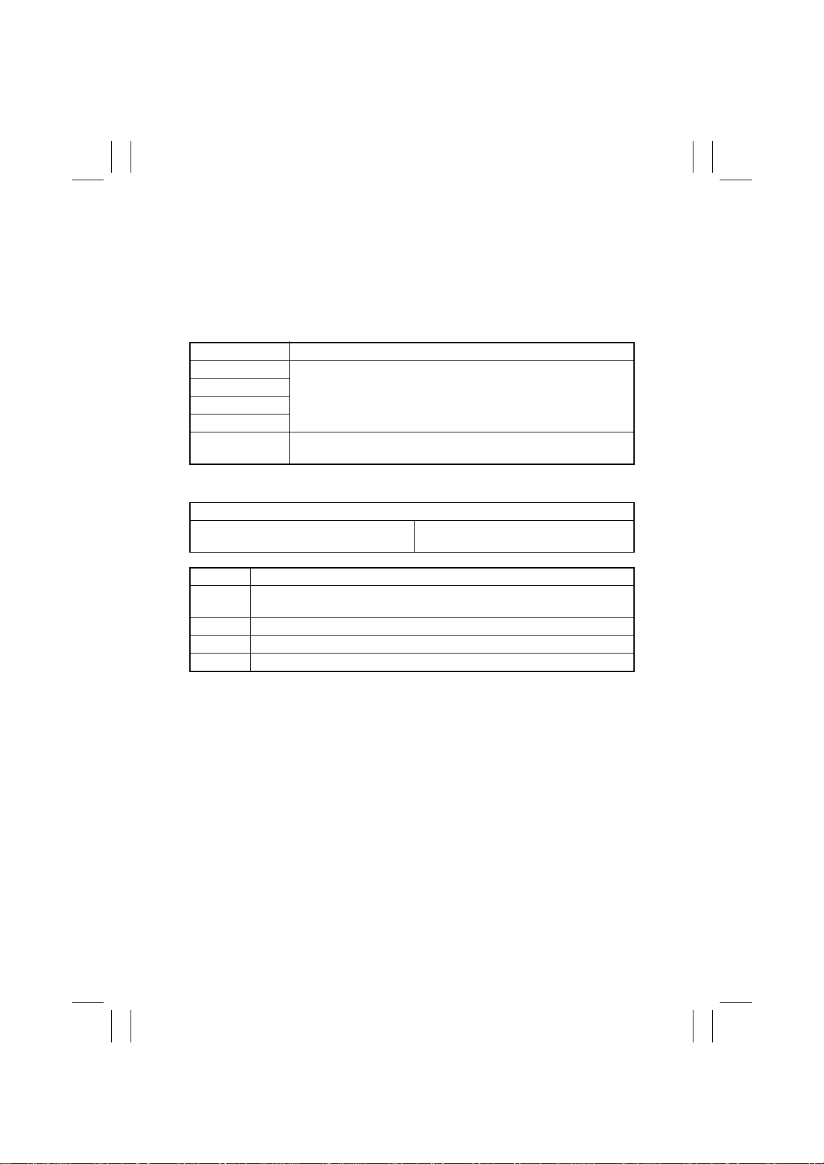
(9) P-23: ATVC(C) failure
(10) P-24: ATVC(M) failure
(11) P-25: ATVC(Y) failure
(12) P-26: ATVC(Bk) failure
(13) P-27: ATVC(2nd) failure
<Detection Timing>
Warning Code Description
P-23
P-24
P-25
P-26
P-27
<Action>
High Voltage Unit
(Image Transfer, Neutralizing) HV2
An abnormal average value is detected during an adjustment of the
first image transfer ATVC value of each color.
An abnormal average value is detected during an adjustment of the
second image transfer ATVC value.
Relevant Electrical Parts
IO Board (PWB-IO)
Image Transfer Belt Unit
Step Action
Check the contact of the Transf er Belt Unit and that of HV2 f or connection and
1
clean or correct the contact as necessary.
2 Change the Image Transfer Belt Unit.
3 Change HV2.
4 Change PWB-IO.
T-34
Page 37
FrameMaker Ver.5.5E(PC) 8020/8031 TROUBLESHOOT ING
02.08.19
3-2. Malfunction Detection Timing and Troubleshooting Proce-
dure
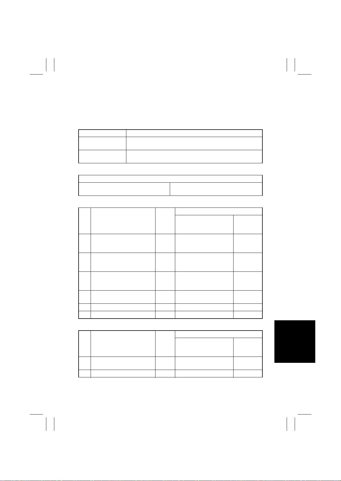
(1) C0000: Main Motor’s failure to turn
(2) C0001: Main Motor Turning at abnormal timing
<Detection Timing>
Malfunction Code Description
C0000
C0001
<Action>
Main Motor (M13) IO Board (PWB-IO)
✽
C0000
Step Action
Check the M13 connector for
1
proper connection and correct
as necessary.
Check M13 for proper drive
2
coupling and correct as necessary.
Check the PU1 connector for
3
proper connection and correct
as necessary.
4 M13 operation check T-3
5 Change PWB-IO. —— —
6 Change PU1. —— —
The Main Motor Lock signal remains HIGH for a predetermined
continuous period of time while the Main Motor is turning.
The Main Motor Lock signal remains LOW for a predetermined
continuous period of time while the Main Motor remains stationary.
Relevant Electrical Parts
DC Power Supply 1 (PU1)
WIRING DIAGRAM
Ref.
Page
—— —
—— —
— PU1 PJ6 PU1-1 (DC24V) 28-G
Control Signal
PWB-IO PJ5IO-1A (LOCK)
PWB-IO PJ5IO-4A (RE M)
Location
(Electrical
Component)
35-A
✽
C0001
WIRING DIAGRAM
Step Action
1 M13 operation check T-3
2 Change PWB-IO. —— —
Ref.
Page
Control Signal
PWB-IO PJ5IO-1A (LOCK)
PWB-IO PJ5IO-4A (RE M)
Location
(Electrical
Component)
35-A
T-35
Page 38
FrameMaker Ver.5.5E(PC) 8020/8031 TROUBLESHOOT ING
02.08.19
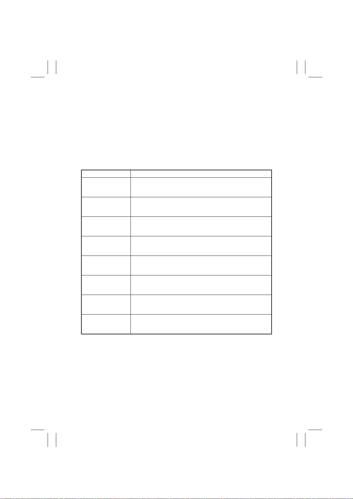
(3) C0010: Imaging Unit Motor C’s failure to turn
(4) C0011: Imaging Unit C turning at abnormal timing
(5) C0012: Imaging Unit Motor M’s failure to turn
(6) C0013: Imaging Unit M turning at abnormal timing
(7) C0014: Imaging Unit Motor Y’s failure to turn
(8) C0015: Imaging Unit Y turning at abnormal timing
(9) C0016: Imaging Unit Motor Bk’s failure to turn
(10) C0017: Imaging Unit Bk turning at abnormal timing
<Detection Timing>
Malfunction Code Description
The Imaging Unit Motor C Lock signal remains HIGH for a prede-
C0010
C0011
C0012
C0013
C0014
C0015
C0016
C0017
termined continuous period of time while the Imaging Unit Motor C
is turning.
The Imaging Unit Motor C Lock signal remains LOW for a predetermined continuous period of time while the Imaging Unit Motor C
remains stationary.
The Imaging Unit Motor M Lock signal remains HIGH for a predetermined continuous period of time while the Imaging Unit Motor M
is turning.
The Imaging Unit Motor M Lock signal remains LOW for a predetermined continuous period of time while the Imaging Unit Motor M
remains stationary.
The Imaging Unit Motor Y Lock signal remains HIGH for a predetermined continuous period of time while the Imaging Unit Motor Y
is turning.
The Imaging Unit Motor Y Lock signal remains LOW for a predetermined continuous period of time while the Imaging Unit Motor Y
remains stationary.
The Imaging Unit Motor Bk Lock signal remains HIGH for a predetermined continuous period of time while the Imaging Unit Motor
Bk is turning.
The Imaging Unit Motor Bk Lock signal remains LOW for a predetermined continuous period of time while the Imaging Unit Motor
Bk remains stationary.
T-36
Page 39
FrameMaker Ver.5.5E(PC) 8020/8031 TROUBLESHOOT ING
02.08.19
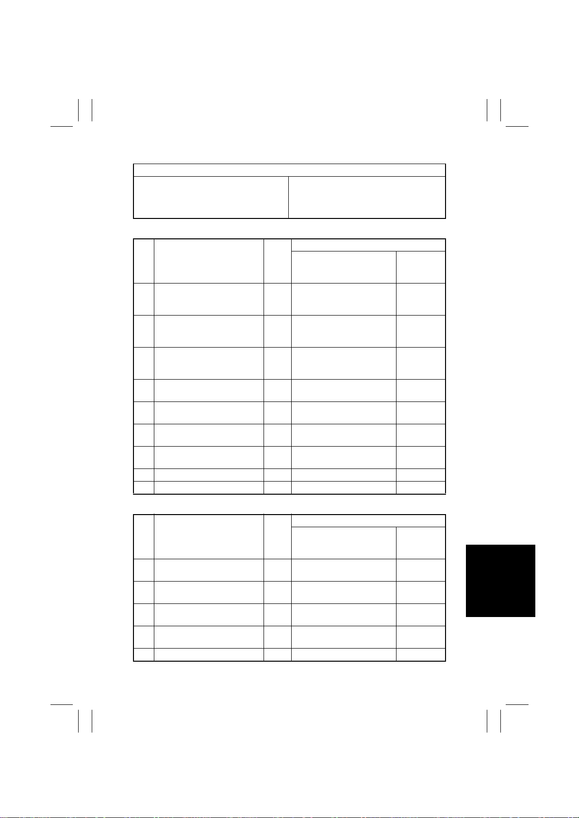
<Action>
Relevant Electrical Parts
IU Motor C (M17)
IU Motor M (M1 6)
IU Motor Y (M15)
IU Motor Bk (M 18)
✽
C0010, C0012, C0014, C0016
Step Action
Check the connector of each
1
motor for proper connection
and correct as necessary.
Check the connector of each
2
motor for proper drive cou-
pling and correct as necessary.
Check the PU1 connector for
3
proper connection and correct
as necessary.
4 M15 operation check T-3
5 M16 operation check T-3
6 M17 operation check T-3
7 M18 operation check T-3
8 Change PWB-IO. —— —
9 Change PU1. —— —
IO Board (PWB-IO)
DC Power Supply 1 (PU1)
WIRING DIAGRAM
Ref.
Page
—— —
—— —
— PU1 PJ7PU1-1 (DC24V) 28-G
Control Signal
PWB-IO PJ17IO-5A (LOCK)
PWB-IO PJ17IO-6A (REM)
PWB-IO PJ17IO-11A(LO CK)
PWB-IO PJ17IO-12A (REM)
PWB-IO PJ17IO-5B (LOCK)
PWB-IO PJ17IO-6B(REM)
PWB-IO PJ17IO-11B(LO CK)
PWB-IO PJ17IO-12B (REM)
Location
(Electrical
Component)
16-A
17-B
16-C
18-C
✽
C0011, C0013, C0015, C0017
WIRING DIAGRAM
Step Action
1 M15 operation check T-3
2 M16 operation check T-3
3 M17 operation check T-3
4 M18 operation check T-3
5 Change PWB-IO. —— —
Ref.
Page
Control Signal
PWB-IO PJ17IO-5A (LOCK)
PWB-IO PJ17IO-6A(REM)
PWB-IO PJ17IO-11A(LO CK)
PWB-IO PJ17IO-12A (REM)
PWB-IO PJ17IO-5B (LOCK)
PWB-IO PJ17IO-6B(REM)
PWB-IO PJ17IO-11B(LO CK)
PWB-IO PJ17IO-12B (REM)
Location
(Electrical
Component)
16-A
17-B
16-C
18-C
T-37
Page 40
FrameMaker Ver.5.5E(PC) 8020/8031 TROUBLESHOOT ING
02.08.19
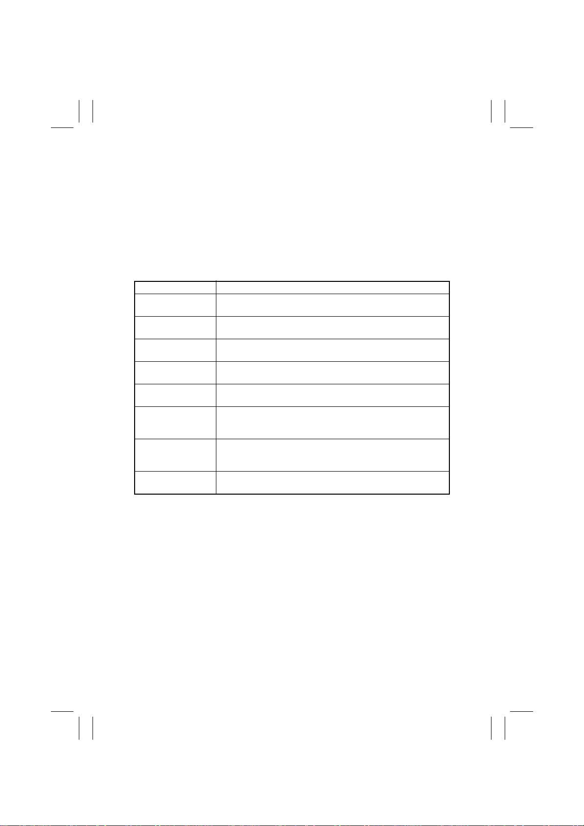
(11) C0040: Suction Fan Motor’s failure to turn
(12) C0043: Cooling Fan Motor 1’s failure to turn
(13) C0044: Cooling Fan Motor 3’s failure to turn
(14) C0045: Cooling Fan Motor 4/5’s failure to turn
(15) C0046: Fusing Cooling Fan Motor’s failure to turn
(16) C004C: Ozone Ventilation Fan Motor’s failure to turn
(17) C004E: Power Supply Cooling Fan Motor’s failure to turn
(18) C004F: Cooling Fan Motor 2’s failure to turn
<Detection Timing>
Malfunction Code Description
C0040
C0043
C0044
C0045
C0046
C004C
C004E
C004F
The Fan Lock signal remains HIGH for a predetermined continuous period of time while the Suction Fan Motor is turning.
The Fan Lock signal remains HIGH for a predetermined continuous period of time while the Cooling Fan Motor 1 is turning.
The Fan Lock signal remains HIGH for a predetermined continuous period of time while the Cooling Fan Motor 3 is turning.
The Fan Lock signal remains HIGH for a predetermined continuous period of time while the Cooling Fan Motor 4/5 is turning.
The Fan Lock signal remains HIGH for a predetermined continuous period of time while the Fusing Cooling Fan Motor is turning.
The Fan Lock signal remains HIGH for a predetermined continuous period of time while the Ozone Ventilation Fan Motor is turning.
The Fan Lock signal remains HIGH for a predetermined continuous period of time while the Power Supply Cooling Fan Motor is
turning.
The Fan Lock signal remains HIGH for a predetermined continuous period of time while the Cooling Fan Motor 2 is turning.
T-38
Page 41
FrameMaker Ver.5.5E(PC) 8020/8031 TROUBLESHOOT ING
02.08.19
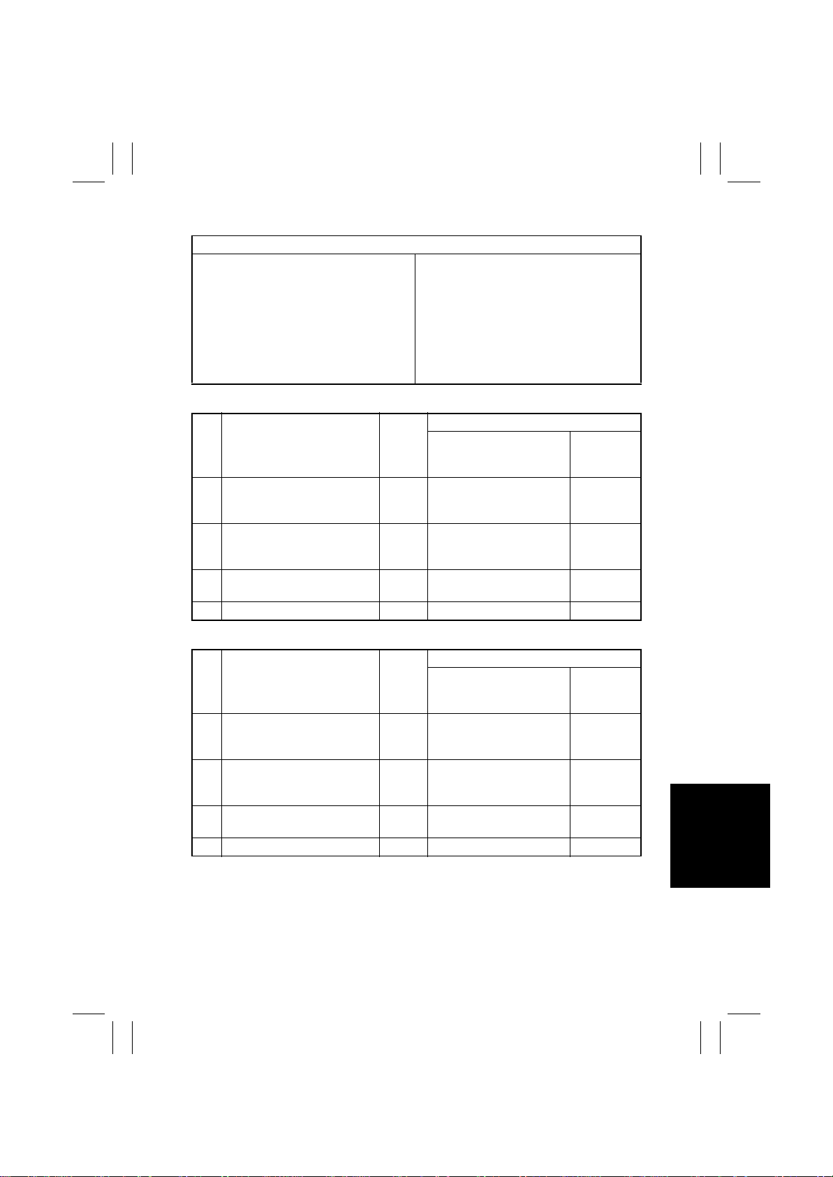
<Action>
Relevant Electrical Parts
Suction Fan Motor (M23)
Cooling Fan Motor 1 (M25)
Cooling Fan Motor 2 (M26)
Cooling Fan Motor 3 (M27)
Cooling Fan Motor 4 (M28)
Cooling Fan Motor 5 (M29)
Fusing Cooling Fan Motor (M24)
Ozone Ventilation Fan Motor (M22)
Power Supply Cooling Fan Motor (M21)
✽
C0040
Step Action
Check the motor connector for
1
proper connection and correct
as necessary.
Check the fan for possible
2
overload and correct as neces-
sary.
3 M23 operation check T-3
4 Change PWB-IO. —— —
High Voltage Unit (Developing Bias) HV3
IO Board (PWB-IO)
DC Power Supply 1 (PU1)
DC Power Supply 2 (PU2)
WIRING DIAGRAM
Ref.
Page
—— —
—— —
Control Signal
PWB-IO PJ10IO-13(LOCK)
PWB-IO PJ10IO-11(REM)
Location
(Electrical
Component)
2-H
✽
C0043
WIRING DIAGRAM
Step Action
Check the motor connector for
1
proper connection and correct
as necessary.
Check the fan for possible
2
overload and correct as neces-
sary.
3 M25 operation check T-3
4 Change PWB-IO. —— —
Ref.
Page
—— —
—— —
Control Signal
PWB-IO PJ6IO-14(LOCK)
PWB-IO PJ6IO-12(REM)
Location
(Electrical
Component)
35-A
T-39
Page 42
FrameMaker Ver.5.5E(PC) 8020/8031 TROUBLESHOOT ING
02.08.19
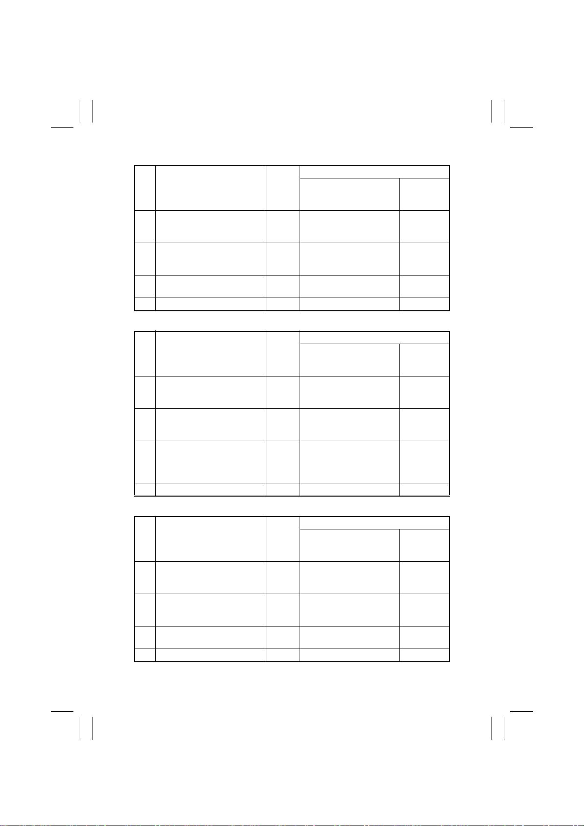
✽
C0044
WIRING DIAGRAM
Step Action
Check the motor connector for
1
proper connection and correct
as necessary.
Check the fan for possible
2
overload and correct as neces-
sary.
3 M27 operation check T-3
4 Change PWB-IO. —— —
✽
C0045
Step Action
Check the motor connector for
1
proper connection and correct
as necessary.
Check the fan for possible
2
overload and correct as neces-
sary.
3 M28, M29 operation check T-3
4 Change PWB-IO. —— —
Ref.
Page
—— —
—— —
Ref.
Page
—— —
—— —
Control Signal
PWB-IO PJ29IO-3(LOCK)
PWB-IO PJ29IO-1(R E M )
WIRING DIAGRAM
Control Signal
PJ25IO-4B(LOCK): M28
PJ25IO-2B(REM): M28
PJ25IO-9B(LOCK): M29
PJ25IO-7B(REM): M29
Location
(Electrical
Component)
35-B
Location
(Electrical
Component)
35-B: M28
35-C: M29
✽
C0046
WIRING DIAGRAM
Step Action
Check the motor connector for
1
proper connection and correct
as necessary.
Check the fan for possible
2
overload and correct as neces-
sary.
3 M24 operation check T-3
4 Change PU2. —— —
Ref.
Page
—— —
—— —
Control Signal
PU2 CN2PU2-9(LOCK)
PU2 CN2PU2-7(REM)
Location
(Electrical
Component)
2-F
T-40
Page 43
FrameMaker Ver.5.5E(PC) 8020/8031 TROUBLESHOOT ING
02.08.19
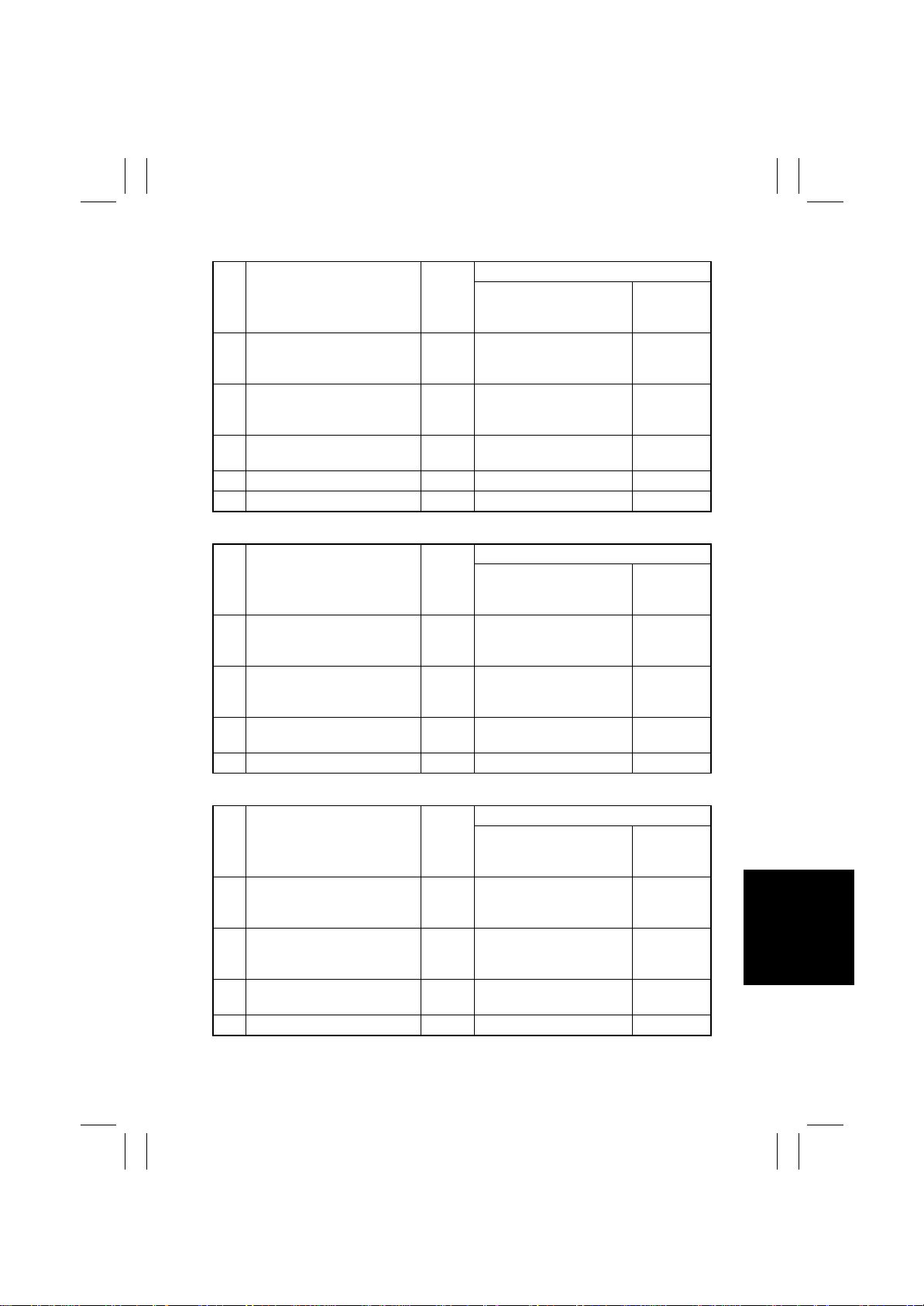
✽
C004C
WIRING DIAGRAM
Step Action
Check the motor connector for
1
proper connection and correct
as necessary.
Check the fan for possible
2
overload and correct as neces-
sary.
3 M22 operation check T-3
4 Change PWB-IO. —— —
5 Change HV3. ——19-B, C
✽
C004E
Step Action
Check the motor connector for
1
proper connection and correct
as necessary.
Check the fan for possible
2
overload and correct as neces-
sary.
3 M21 operation check T-3
4 Change PU1. —— —
Ref.
Page
—— —
—— —
Ref.
Page
—— —
—— —
Control Signal
PWB-IO PJ23IO-15(LOCK)
PWB-IO PJ23IO-14(REM)
WIRING DIAGRAM
Control Signal
PU1 PJ12PU1-1(LOCK)
PU1 PJ12PU1-3(REM)
Location
(Electrical
Component)
19-A
Location
(Electrical
Component)
29-I
✽
C004F
WIRING DIAGRAM
Step Action
Check the motor connector for
1
proper connection and correct
as necessary.
Check the fan for possible
2
overload and correct as neces-
sary.
3 M26 operation check T-3
4 Change PWB-IO. —— —
Ref.
Page
—— —
—— —
Control Signal
PWB-IO PJ28IO-9(LOCK)
PWB-IO PJ28IO-7(R E M )
Location
(Electrical
Component)
35-B
T-41
Page 44
FrameMaker Ver.5.5E(PC) 8020/8031 TROUBLESHOOT ING
02.08.19
(19) C0060: Fusing Drive Motor’s failure to turn
(20) C0061: Fusing Drive Motor turning at abnormal timing
<Detection Timing>
Malfunction Code Description
C0060
C0061
<Action>
Fusing Drive Motor (M14) IO Board (PWB-IO)
✽
C0060
Step Action
Check the M14 connector for
1
proper connection and correct
as necessary.
Check the Fusing Unit drive for
2
possible overload and correct
as necessary.
Check the PU1 connector for
3
proper connection and correct
as necessary.
4 M14 operation check T-3
5 Change PWB-IO. —— —
6 Change PU1. —— —
The Fusing Drive Motor Lock signal remains HIGH for a predetermined continuous period of time while the Fusing Drive Motor is
turning.
The Fusing Drive Motor Lock signal remains LOW for a predetermined continuous period of time while the Fusing Drive Motor
remains stationary.
Relevant Electrical Parts
DC Power Supply 1 (PU1)
WIRING DIAGRAM
Ref.
Page
—— —
—— —
— PU1 PJ 6PU1- 1(DC24V ) 28-G
Control Signal
PWB-IO PJ5IO-7A(L OCK)
PWB-IO PJ5IO-10A(REM )
Location
(Electrical
Component)
2-E
✽
C0061
WIRING DIAGRAM
Step Action
1 M14 operation check T-3
2 Change PWB-IO. —— —
Ref.
Page
Control Signal
PWB-IO PJ5IO-7A(L OCK)
PWB-IO PJ5IO-10A(REM )
Location
(Electrical
Component)
2-E
T-42
Page 45
FrameMaker Ver.5.5E(PC) 8020/8031 TROUBLESHOOT ING
02.08.19
(21) C0094: 2nd Image Transfer Roller pressure/retraction failure
<Detection Timing>
Malfunction Code Description
• The 2nd Image Transfer Pressure Position Sensor is not activated (retracted position) within 2 sec. after the 2nd Image
Transfer Pressure/Retraction Motor has started turning during a
C0094
<Action>
2nd Image Transfer Pressure Position
Sensor (PC23)
2nd Image Transfer Pressure/Retraction
Motor (M12)
Step Action
Check the M12 connector for
1
proper connection and correct
as necessary.
2 PC23 I/O check
3 M12 operation check T-3 PWB-IO PJ1 0IO-9(RE M) 5-D
4 Change PWB-IO. —— —
sequence of the 2nd Image T r ansfer Roller's retracting motion.
• The 2nd Image Transfer Pressure Position Sensor is not deactivated (pressed position) within 2 sec. after the 2nd Image Transfer Pressure/Retraction Motor has started turning during a
sequence of the 2nd Image T r ansfer Roller's pressing motion.
Relevant Electrical Parts
IO Board (PWB-IO)
WIRING DIAGRAM
Ref.
Page
—— —
T-4 t o
T-1 0
Control Signal
— 5-E
Location
(Electrical
Component)
T-43
Page 46
FrameMaker Ver.5.5E(PC) 8020/8031 TROUBLESHOOT ING
02.08.19
(22) C0096: Image Transfer Belt pressure/retraction failure
<Detection Timing>
Malfunction Code Description
• The 1st Image Transfer Retraction Position Sensor is not activated (retracted position) within 3 sec. after the 1st Image Transfer Pressure/Retraction Motor has started turning during a
C0096
<Action>
1st Image Transfer Retraction Position
Sensor (PC28)
1st Image Transfer Pressure/Retraction
Motor (M11)
Step Action
Check the M11 connector for
1
proper connection and correct
as necessary.
2 PC28 I/O check
3 M11 operation check T-3
4 Change PWB-IO. —— —
sequence of the Transfer Belt's retracting motion.
• The 1st Image Transfer Retraction Position Sensor is not deactivated (pressed position) within 1 sec. after the 1st Image Transfer Pressure/Retraction Motor has started turning during a
sequence of the Transfer Belt's pressing motion.
Relevant Electrical Parts
IO Board (PWB-IO)
WIRING DIAGRAM
Ref.
Page
—— —
T-4 t o
T-1 0
Control Signal
— 5-E
PWB-IO PJ16IO-1 to 4
(Pulse Output)
Location
(Electrical
Component)
5-D
T-44
Page 47
FrameMaker Ver.5.5E(PC) 8020/8031 TROUBLESHOOT ING
02.08.19
(23) C0098: Fusing Pressure Roller pressure/retraction failure
<Detection Timing>
Malfunction Code Description
• No change is observed in the encoder pulse of the Fusing Pressure/Retraction Motor even after the lapse of 0.5 sec. after the
motor has started turning for a sequence of the Fusing Pressure
Roller's retracting motion.
• No change is observed in the encoder pulse of the Fusing Pres-
C0098
<Action>
Fusing Pressure/Retraction Motor (M8)
sure/Retraction Motor even after the lapse of 0.5 sec. after the
motor has started turning for a sequence of the Fusing Pressure
Roller's pressing motion.
• The Fusing Pressure Position Sensor is not activated (pressed
position) even when 21 encoder pulses of the Fusing Pressure/
Retraction Motor are counted after the motor has started turning
for a sequence of the Fusing Pressure Roller's pressing motion.
Relevant Electrical Parts
IO Board (PWB-IO)
Fusing Unit
WIRING DIAGRAM
Step Action
Check the M8 connector for
1
proper connection and correct
as necessary.
2 M8 operation check T-3 PWB-IO PJ13IO-4, 5 2-E
3 Change Fusing Unit. —— —
4 Change PWB-IO. —— —
Ref.
Page
—— —
Control Signal
Location
(Electrical
Component)
T-45
Page 48
FrameMaker Ver.5.5E(PC) 8020/8031 TROUBLESHOOT ING
02.08.19
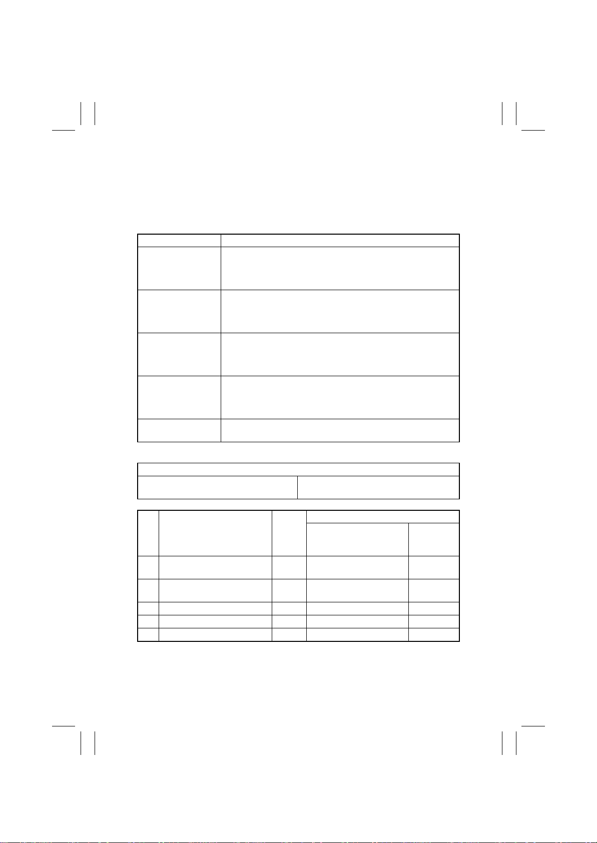
(24) C0200: Cyan PC Drum Charge Corona malfunction
(25) C0202: Magenta PC Drum Charge Corona malfunction
(26) C0204: Yellow PC Drum Charge Corona malfunction
(27) C0206: Black PC Drum Charge Corona malfunction
(28) C0208: PC Drum Charge Corona malfunction
<Detection Timing>
Malfunction Code Description
The SCD signal is detected for a continuous 0.7-sec. period when
C0200
C0202
C0204
C0206
C0208
the Cyan PC Drum Charge Corona is automatically energized as
the malfunction is reset after C0208 (PC Drum Charge Corona
malfunction) has been detected.
The SCD signal is detected for a continuous 0.7-sec. period when
the Magenta PC Drum Charge Corona is automatically energized
as the malfunction is reset after C0208 (PC Drum Charge Corona
malfunction) has been detected.
The SCD signal is detected for a continuous 0.7-sec. period when
the Yellow PC Drum Charge Corona is automatically energized as
the malfunction is reset after C0208 (PC Drum Charge Corona
malfunction) has been detected.
The SCD signal is detected for a continuous 0.7-sec. period when
the Black PC Drum Charge Corona is automatically energized as
the malfunction is reset after C0208 (PC Drum Charge Corona
malfunction) has been detected.
The SCD signal is detected for a continuous 0.7-sec. period while
the PC Drum Charge Corona is being energized.
<Action>
Relevant Electrical Parts
IU C/M/Y/Bk High Voltage Unit (PC Drum CH.) HV1
Step Action
Check the IU contact and cor1
rect or clean as necessary.
Check the HV1 contact and
2
correct or clean as necessary.
3 Change IU. —— —
4 Change HV1. —— —
5 Change PWB-IO —— —
IO Board (PWB-IO)
WIRING DIAGRAM
Ref.
Page
—— —
—— —
Control Signal
Location
(Electrical
Component)
T-46
Page 49
FrameMaker Ver.5.5E(PC) 8020/8031 TROUBLESHOOT ING
02.08.19
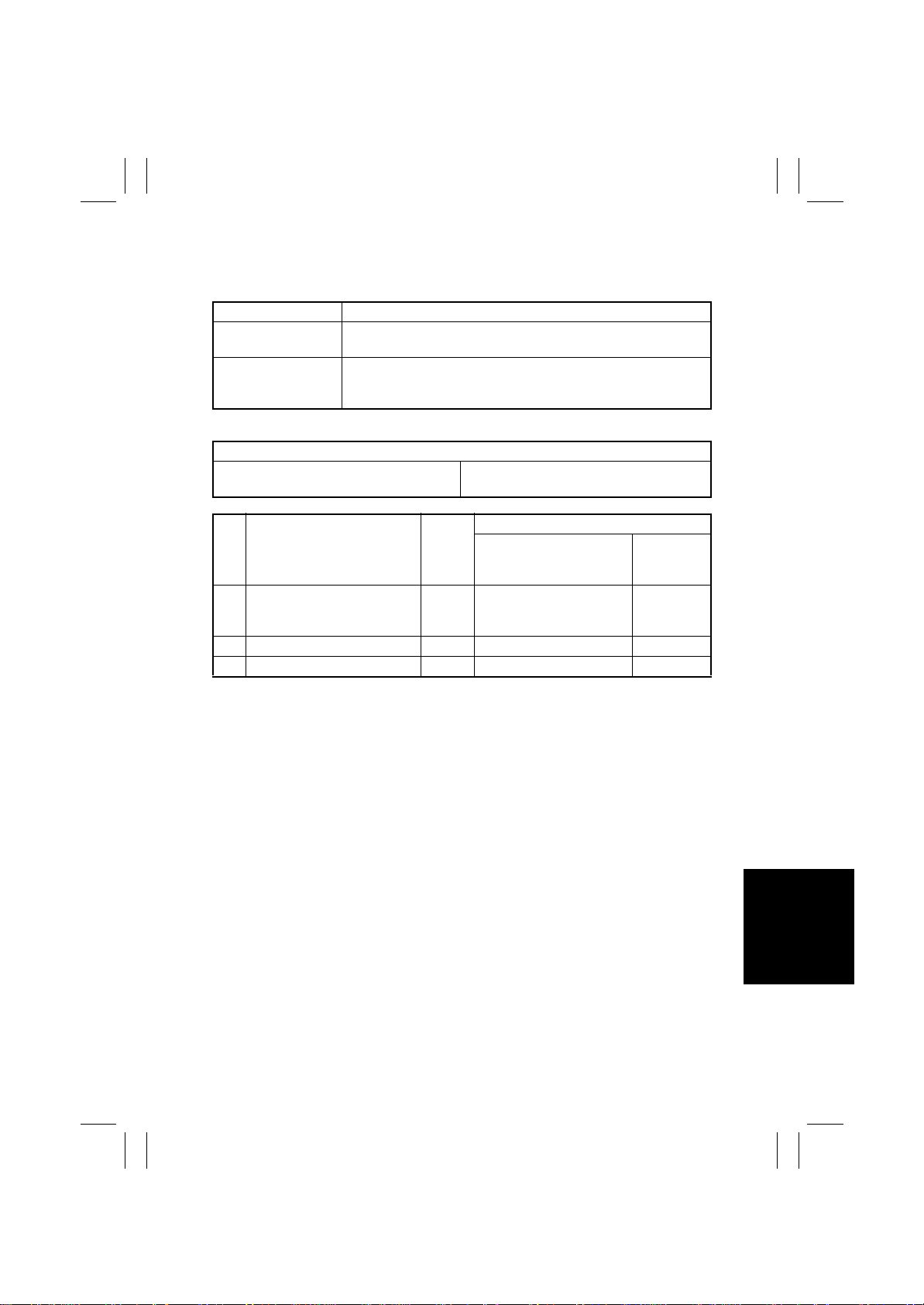
(29) C0400: Exposure Lamp’s failure to turn ON
(30) C0410: Exposure Lamp turning ON at abnormal timing
<Detection Timing>
Malfunction Code Description
C0400
C0410
<Action>
Scanner Assy
Flat Cable
Step Action
Check the flat cable for proper
1
connection and correct or
change as necessary.
2 Change Scanner Assy. —— —
3 Change PWB-C. —— —
The output from the CCD Sensor is a predetermined value or less
during CCD Sensor gain adjustment.
The average output value of the CCD Sensor with the Scanner at
its standby position is a predetermined value or more at the end of
a scan job.
Relevant Electrical Parts
Image Processing Board (PWB-C)
WIRING DIAGRAM
Ref.
Page
—— —
Control Signal
Location
(Electrical
Component)
T-47
Page 50
FrameMaker Ver.5.5E(PC) 8020/8031 TROUBLESHOOT ING
02.08.19
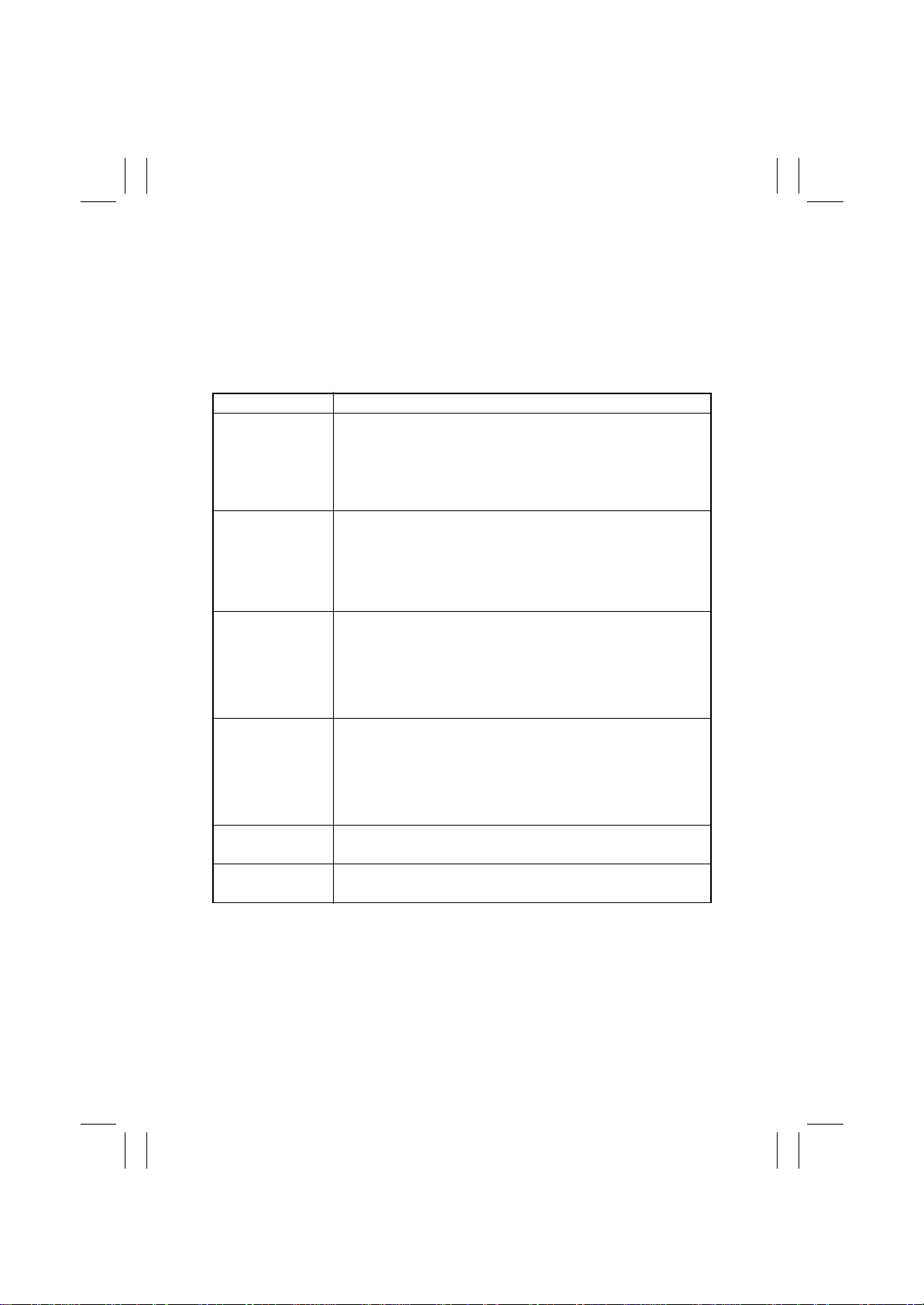
(31) C0500: Heating Roller warm-up failure
(32) C0501: Fusing Pressure Roller warm-up failure
(33) C0510: Heating Roller abnormally low temperature
(34) C0511: Fusing Pressure Roller abnormally low temperature
(35) C0520: Heating Roller abnormally high temperature
(36) C0521: Fusing Pressure Roller abnormally high temperature
<Detection Timing>
Malfunction Code Description
• The Heating Roller Thermistor does not detect a predetermined
temperature within 550 sec. after a warm-up cycle has been
C0500
C0501
C0510
C0511
C0520
C0521
started and thus the copier does not complete the warm-up cycle.
• The output from the Heating Roller Thermistor does not rise
beyond a predetermined level within 30 sec. after the Heating
Roller Heater Lamps have lit up.
• The temperature detected by the Fusing Pressure Roller Ther-
°
mistor does not reach 100
cycle has been started.
• The output from the Heating Roller Thermistor does not rise
beyond a predetermined level within 120 sec. after the Fusing
Pressure Roller Heater Lamp has lit up.
• The Heating Roller Thermistor detects 160
more while the copier is in the standby state.
• The Heating Roller Thermistor detects 160
more while the copier is in a print cycle.
• The Heating Roller Thermistor detects 70
more while the copier is in the Low Power mode.
• The Fusing Pressure Roller Thermistor detects 100
1 sec. or more while the copier is in the standby state.
• The Fusing Pressure Roller Thermistor detects 100
1 sec. or more while the copier is in a print cycle.
• The Fusing Pressure Roller Thermistor detects 100
1 sec. or more while the copier is in the Low Power mode.
The Heating Roller Thermistor detects 220
more.
The Fusing Pressure Roller Thermistor detects 215
sec. or more.
C within 230 sec. after a warm-up
°
°
°
C or less for 1 sec. or
°
C or more for 1 sec. or
C or less for 1 sec. or
C or less for 1 sec. or
°
C or less for
°
C or less for
°
C or less for
°
C or more for 1
T-48
Page 51
FrameMaker Ver.5.5E(PC) 8020/8031 TROUBLESHOOT ING
02.08.19
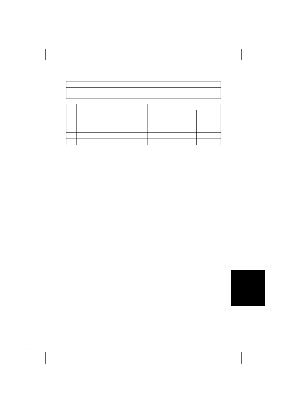
<Action>
Relevant Electrical Parts
Fusing Unit DC Power Supply 1 (PU1)
Step Action
1 Change PWB-IO. —— —
2 Change Fusing Unit. —— —
3 Change PU1. —— —
IO Board (PWB-IO)
Ref.
Page
WIRING DIAGRAM
Control Signal
Location
(Electrical
Component)
T-49
Page 52
FrameMaker Ver.5.5E(PC) 8020/8031 TROUBLESHOOT ING
02.08.19
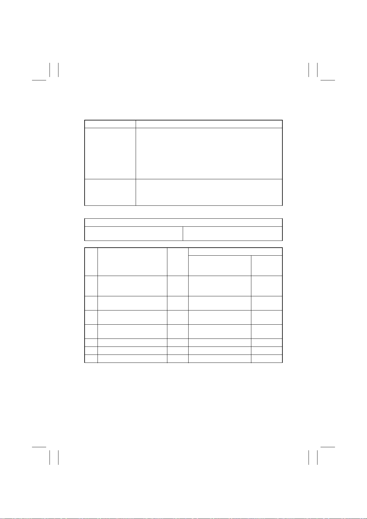
(37) C0650: Scanner Home Sensor malfunction
(38) C0660: Scanner overrun failure
<Detection Timing>
Malfunction Code Description
• The Scanner Home Sensor is unable to detect a Scanner when
the Scanner is at a position to block the sensor.
• The Scanner Home Sensor is unable to detect a Scanner
C0650
C0660
<Action>
Scanner Home Sensor (PC201)
Scanner Motor (M201)
despite the fact that the Scanner Motor has been energized to
move the Scanner over the maximum traveling distance.
• The Scanner Home Sensor detects a Scanner when the Scanner has moved a distance of 5 mm away from the position, at
which it blocks the sensor.
The Scanner Home Sensor detects the Scanner at its home position during a period of time that begins with the time when a prescan command and a scan preparation command are executed and
ends when a home return command is executed.
Relevant Electrical Parts
Scanner Motor Drive Board (PWB-IC)
Image Processing Board (PWB-C)
WIRING DIAGRAM
Step Action
Correct or change the Scanner
1
drive (cable, pulley, gear, belt)
if it is faulty.
Correct the Scanner Motor set
2
screw if loose.
Adjust “Top Image” and “FD-
3
Mag.”
4 PC201 I/O check
5 Change M201. —— 22-G
6 Change PWB-IC. —— —
7 Change PWB-C. —— —
Ref.
Page
—— —
—— —
D-68 ——
T-4 t o
T-1 0
Control Signal
— 26-G
Location
(Electrical
Component)
T-50
Page 53
FrameMaker Ver.5.5E(PC) 8020/8031 TROUBLESHOOT ING
02.08.19
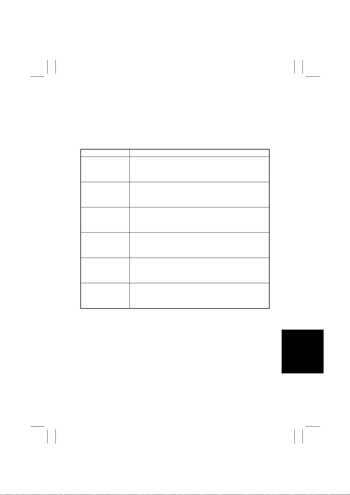
(39) C0F30: Abnormally low toner density detected Cyan ATDC Sensor
(40) C0F31: Abnormally high toner density detected Cyan AT DC Sensor
(41) C0F32: Abnormally low toner density detected Magenta ATDC Sensor
(42) C0F33: Abnormally high toner density detected Magenta ATDC Sensor
(43) C0F34: Abnormally low toner density detected Yellow ATDC Sensor
(44) C0F35: Abnormally high toner de ns ity detected Yellow ATDC Sensor
<Detection Timing>
Malfunction Code Description
Toner density that is 3% or more lower than the target level is
C0F30
C0F31
C0F32
C0F33
C0F34
C0F35
detected ten consecutive times while the Developing Unit is being
energized during a print cycle, ATVC, or image stabilization
sequence.
Toner density that is 4% or more higher than the target level is
detected ten consecutive times while the Developing Unit is being
energized during a print cycle, ATVC, or image stabilization
sequence.
Toner density that is 3% or more lower than the target level is
detected ten consecutive times while the Developing Unit is being
energized during a print cycle, ATVC, or image stabilization
sequence.
Toner density that is 4% or more higher than the target level is
detected ten consecutive times while the Developing Unit is being
energized during a print cycle, ATVC, or image stabilization
sequence.
Toner density that is 3% or more lower than the target level is
detected ten consecutive times while the Developing Unit is being
energized during a print cycle, ATVC, or image stabilization
sequence.
Toner density that is 4% or more higher than the target level is
detected ten consecutive times while the Developing Unit is being
energized during a print cycle, ATVC, or image stabilization
sequence.
T-51
Page 54
FrameMaker Ver.5.5E(PC) 8020/8031 TROUBLESHOOT ING
02.08.19
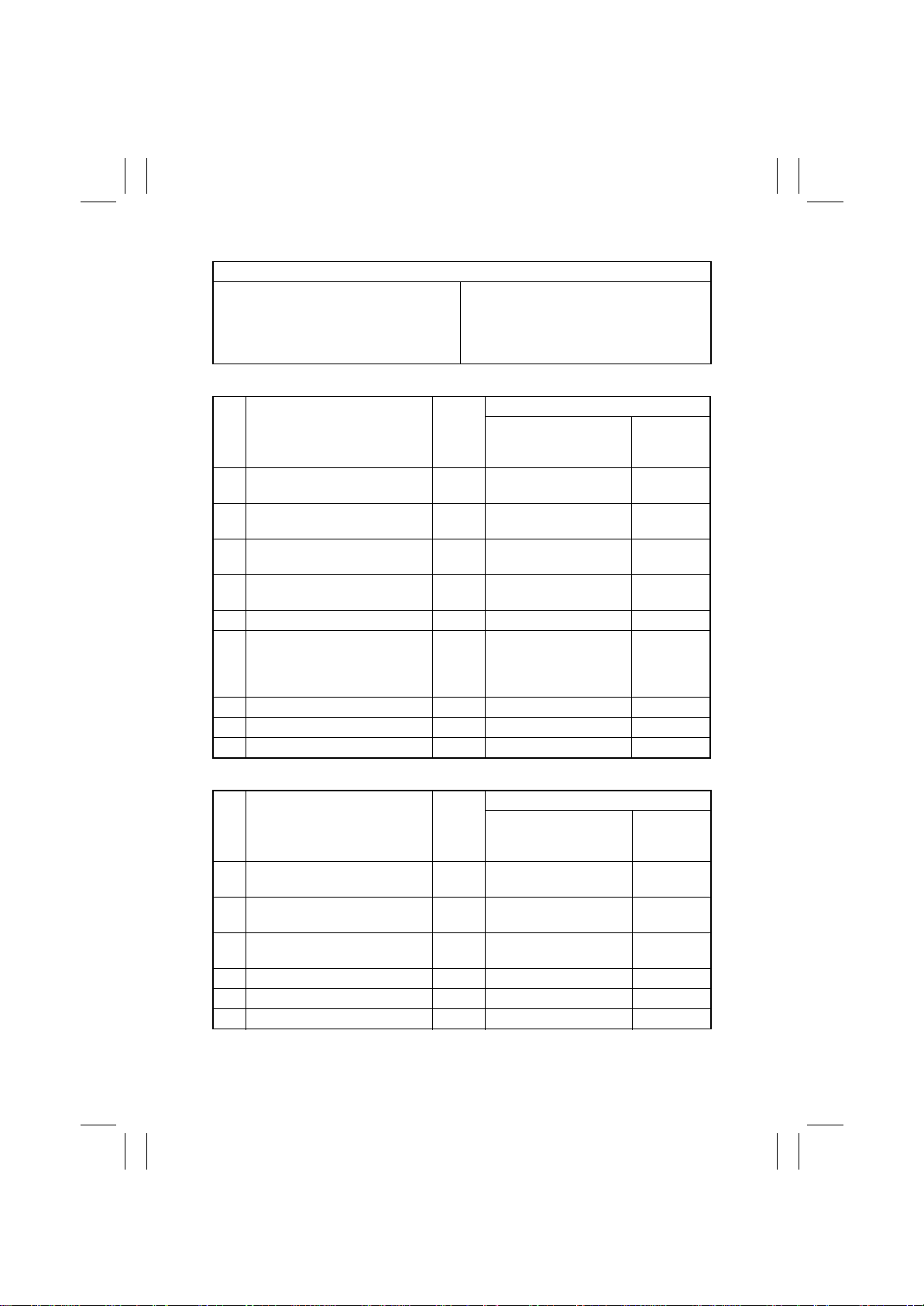
<Action>
Relevant Electrical Parts
ATDC Sensor C (PWB-N3)
ATDC Sensor M (PWB-N2)
ATDC Sensor Y (PWB-N1)
✽
C0F30, C0F32, C0F34
Step Action
Perform image troubleshooting
1
procedure if image density is low.
Clean the ATDC Sensor window
2
on the underside of the IU if dirty.
Correct the ATDC Sensor spring
3
moving part if faulty.
Clean the ATDC Sensor LED if
4
dirty.
5 Change ATDC Sensor C/M/Y. ——10-B,C,D
6 M9, M10 operation check T-3
7 Change IU C/M/Y. —— —
8 Change PWB-IO. —— —
9 Change PWB-PIC. —— —
Toner Replenishing Motor C/Bk (M9)
Toner Replenishing Motor Y/M (M10)
IO Board (PWB-IO)
PIC Board (PWB-PIC)
IU C/M/Y
WIRING DIAGRAM
Ref.
Page
T-9 1 ——
—— —
—— —
—— —
Control Signal
PWB-IO PJ13IO-10 to 13
(Pulse Output): M9
PWB-IO PJ13IO-6 to 9
(Pulse Output): M10
Location
(Electrical
Component)
10-A
✽
C0F31, C0F33, C0F35
WIRING DIAGRAM
Step Action
Clean the ATDC Sensor window
1
on the underside of the IU if dirty.
Clean the ATDC Sensor LED if
2
dirty.
Correct the contact and/or wiring
3
of the ATDC Sensor if faulty.
4 Change ATDC Sensor C/M/Y. ——10-B,C,D
5 Change PWB-IO. —— —
6 Change PWB-PIC. —— —
Ref.
Page
—— —
—— —
—— —
Control Signal
Location
(Electrical
Component)
T-52
Page 55
FrameMaker Ver.5.5E(PC) 8020/8031 TROUBLESHOOT ING
02.08.19
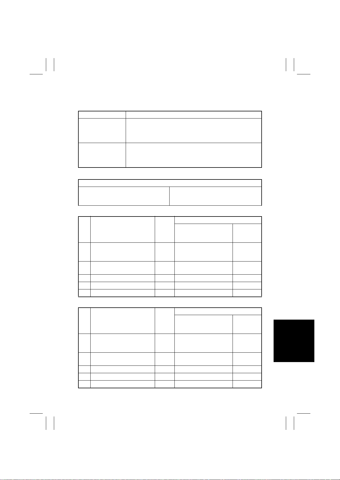
(45) C0F36: Abnormally low toner density detected Cyan ATDC Sensor
(46) C0F37: Abnormally high toner density detected Cyan AT DC Sensor
<Detection Timing>
Malfunction Code Description
Toner density that is 3% or more lower than the target level is
C0F36
C0F37
<Action>
IU Bk Toner Replenishing Motor C/Bk (M9)
✽
C0F36
Step Action
Perform image troubleshoot1
ing procedure if image density
is low.
2 M9 operation check T-3
3 Change IU Bk. — — —
4 Change PWB-IO. — — —
5 Change PWB-PIC — — —
detected ten consecutive times while the Developing Unit is being
energized during a print cycle, ATVC, or image stabilization
sequence.
Toner density that is 4% or more higher than the target level is
detected ten consecutive times while the Developing Unit is being
energized during a print cycle, ATVC, or image stabilization
sequence.
Relevant Electrical Parts
IO Board (PWB-IO)
PIC Board (PWB-PIC)
WIRING DIAGRAM
Ref.
Page
T-9 1 — —
Control Signal
PWB-IO PJ13IO-10 to 1 3
(Pulse Output)
(Electrical
Component)
Location
10-A
✽
C0F37
WIRING DIAGRAM
Step Action
Correct the ATDC connection
1
on the underside of the IU if
faulty.
Clean or correct each contact
2
of the IU if faulty.
3 Change IU Bk. — — —
4 Change PWB-IO. — — —
5 Change PWB-PIC — — —
Ref.
Page
—— —
—— —
Control Signal
Component)
T-53
Location
(Electrical
Page 56
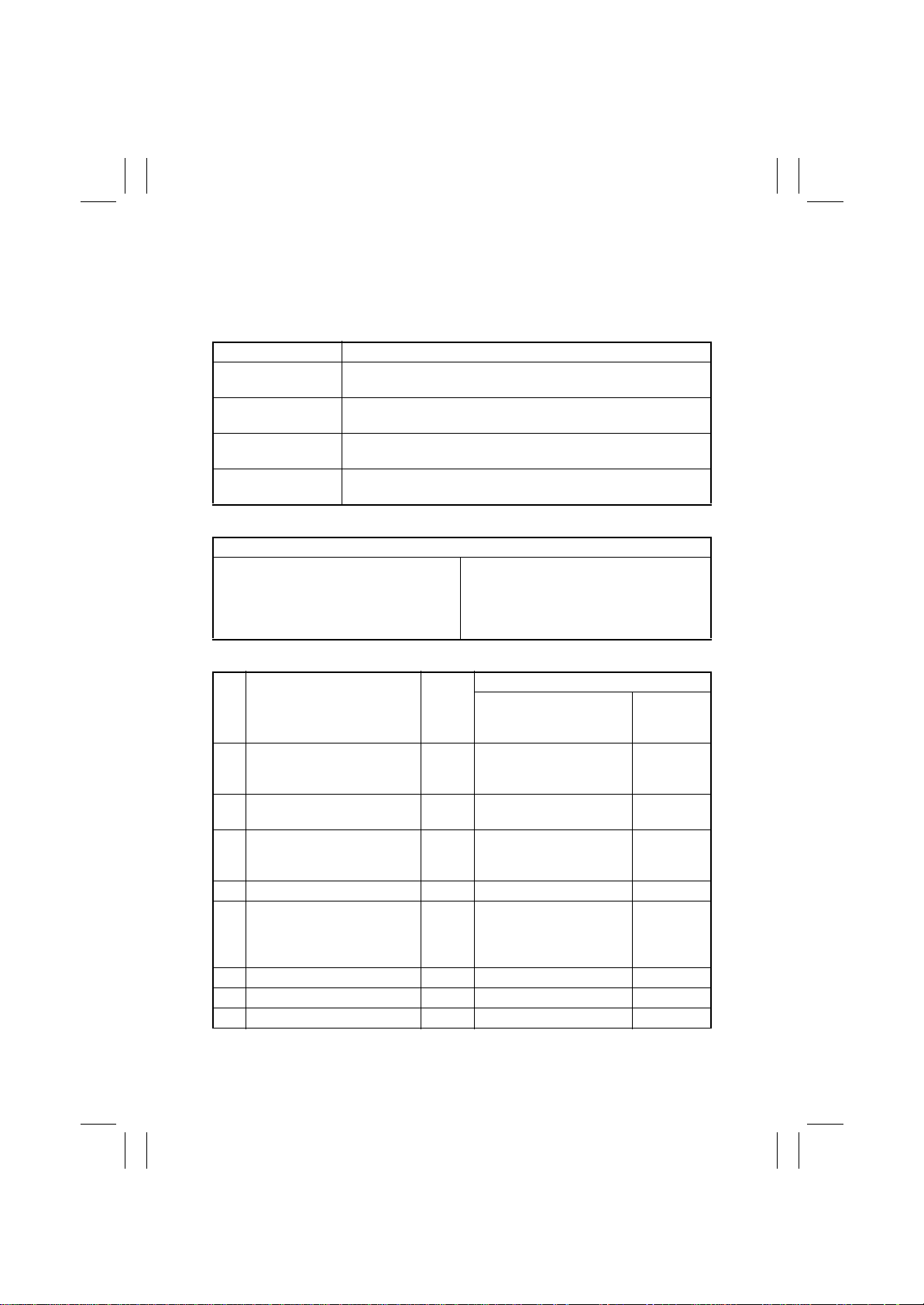
FrameMaker Ver.5.5E(PC) 8020/8031 TROUBLESHOOT ING
02.08.19
(47) C0F3A: Cyan ATDC Sensor adjustment failure
(48) C0F3B: Magenta ATDC Sensor adjustment failure
(49) C0F3C: Yellow ATDC Sensor adjustment failure
(50) C0F3D: Black ATDC Sensor adjustment failure
<Detection Timing>
Malfunction Code Description
C0F3A
C0F3B
C0F3C
C0F3D
<Action>
ATDC Sensor C (PWB-N3)
ATDC Sensor M (PWB-N2)
ATDC Sensor Y (PWB-N1)
Cyan ATDC Sensor automatic adjustment does not function properly, failing to adjust to an appropriate value.
Magenta ATDC Sensor automatic adjustment does not function
properly, failing to adjust to an appropriate value.
Yello w ATDC Sensor automatic adjustment does not function properly, failing to adjust to an appropriate value.
Black ATDC Sensor automatic adjustment does not function properly, failing to adjust to an appropriate value.
Relevant Electrical Parts
Toner Replenishing Motor C/Bk (M9)
Toner Replenishing Motor Y/M (M10)
IO Board (PWB-IO)
PIC Board (PWB-PIC)
IU C/M/Y/Bk
✽
C0F3A, C0F3B, C0F3C
WIRING DIAGRAM
Step Action
Clean the ATDC Sensor win1
dow on the underside of the IU
if dirty .
Clean the ATDC Sensor LED if
2
dirty.
Correct the contact and/or wir3
ing of the ATDC Sensor if
faulty.
4 Reinstall IU C/M/Y. — — —
5 M9, M10 operation check T-3
6 Change IU C/M/Y. — — —
7 Change PWB-IO. — — —
8 Change PWB-PIC — — —
Ref.
Page
—— —
—— —
—— —
Control Signal
Component)
PWB-IO PJ13IO-10 to 1 3
(Pulse Output): M9
PWB-IO PJ13IO-6 to 9
(Pulse Output): M10
T-54
Location
(Electrical
10-A
Page 57
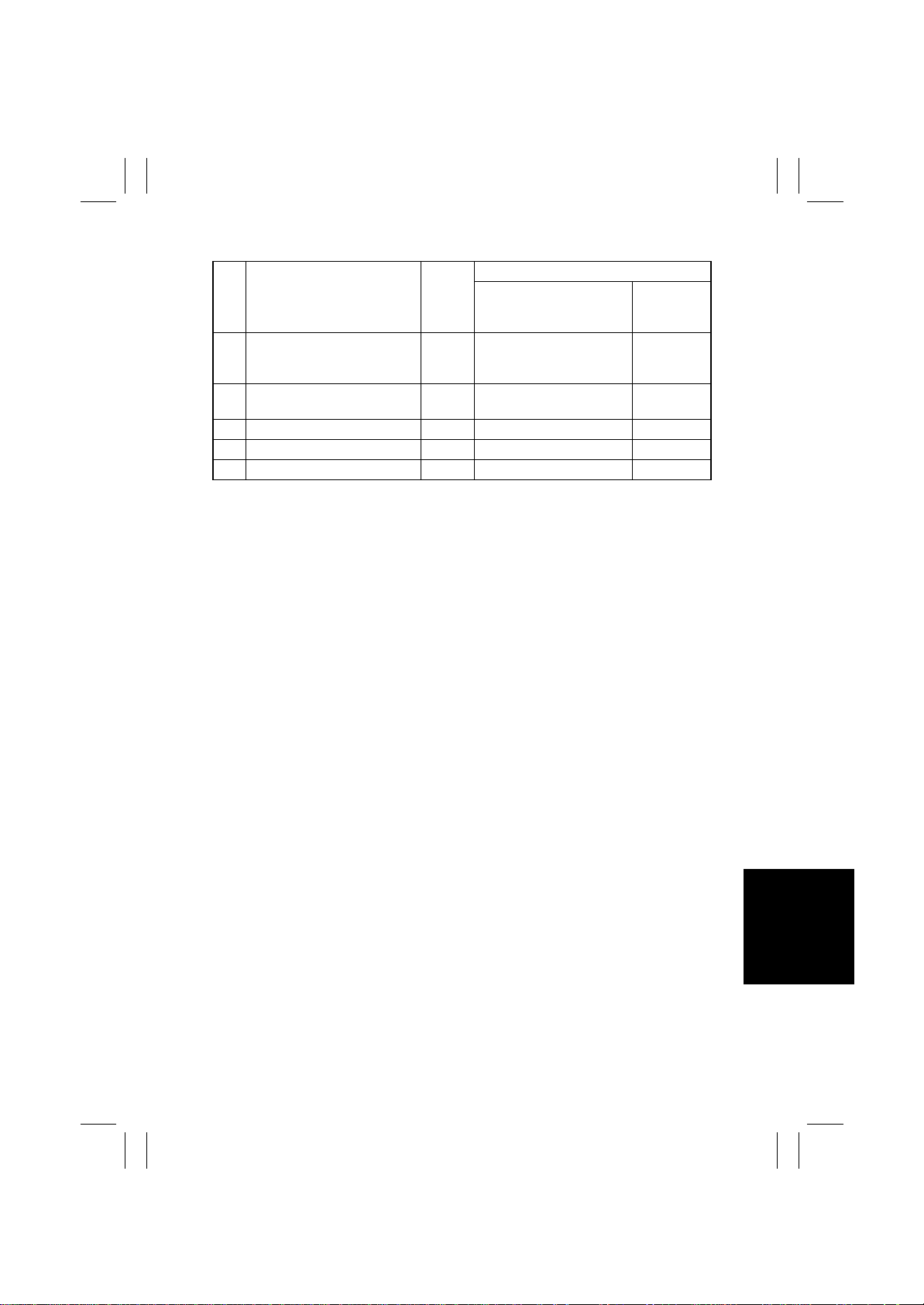
FrameMaker Ver.5.5E(PC) 8020/8031 TROUBLESHOOT ING
02.08.19
✽
C0F3D
WIRING DIAGRAM
Step Action
Correct the ATDC connection
1
on the underside of the IU if
faulty.
Clean or correct each contact
2
of the IU if faulty.
3 Change IU Bk. —— —
4 Change PWB-IO. —— —
5 Change PWB-PIC —— —
Ref.
Page
—— —
—— —
Control Signal
Location
(Electrical
Component)
T-55
Page 58
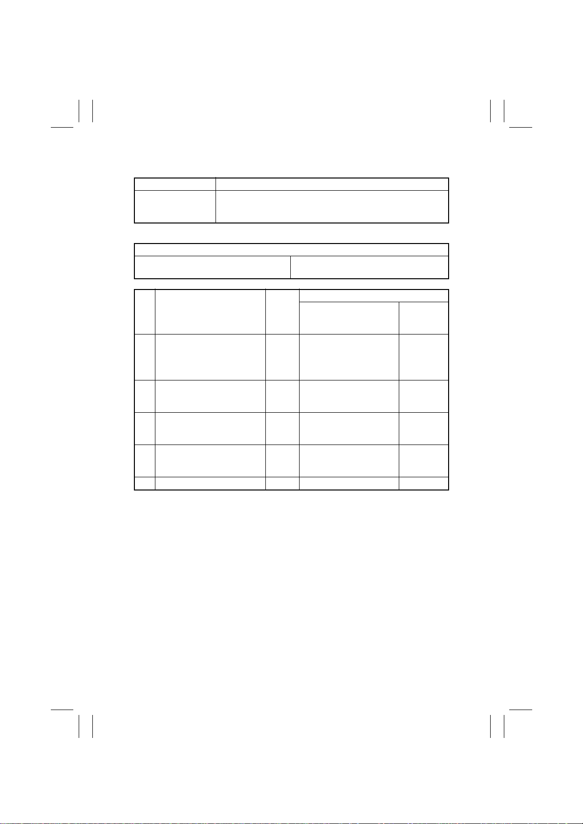
FrameMaker Ver.5.5E(PC) 8020/8031 TROUBLESHOOT ING
02.08.19
(51) C1200: Memory mounting failure
<Detection Timing>
Malfunction Code Description
The WORK memory or Controller Board are not mounted on the
C1200
<Action>
Image Control Board (PWB-F) Controller Board
Step Action
Select “Tech. Rep. Mode”
“System Input”
1
Setting” and check for correct
setting.
Check that WORK memory is
2
correctly mounted on the
Image Control Board (PWB-F).
Change WORK memory on
3
the Image Control Board
(PWB-F).
Change Controller Board on
4
the Image Control Board
(PWB-F).
5 Change PWB-F. —— —
Image Control Board (PWB-F) when the printer controller
X3e 31C-M is installed.
Relevant Electrical Parts
WORK memory (DIMM Board)
WIRING DIAGRAM
Ref.
→
“Peripheral
→
Page
—— —
—— —
—— —
—— —
Control Signal
Location
(Electrical
Component)
T-56
Page 59
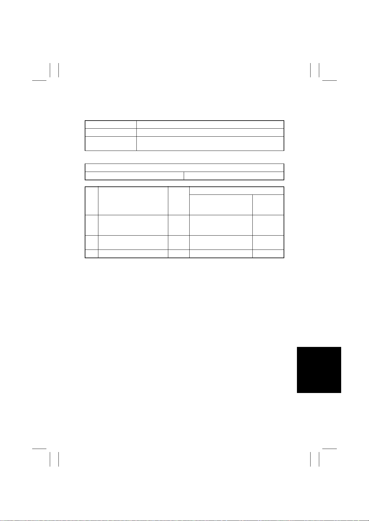
FrameMaker Ver.5.5E(PC) 8020/8031 TROUBLESHOOT ING
02.08.19
(52) C1203: Memory mounting failure
(53) C1204: Memory mounting failure
<Detection Timing>
Malfunction Code Description
C1203 T he FILE mem ory on the Image Control Board (PWB-F) is faulty.
C1204
<Action>
Image Control Board (PWB-F) FILE memory (DIMM Board)
Step Action
Check that FILE memory is
1
correctly mounted on the
Image Control Board (PWB-F).
Change FILE memory on the
2
Image Control Board (PWB-F).
3 Change PWB-F. —— —
The FILE memory on the Image Control Board (PWB-F) is short of
capacity
Relevant Electrical Parts
WIRING DIAGRAM
Ref.
Page
—— —
—— —
Control Signal
Location
(Electrical
Component)
T-57
Page 60
FrameMaker Ver.5.5E(PC) 8020/8031 TROUBLESHOOT ING
02.08.19
(54) C1220: Image Input Time Out
<Detection Timing>
Malfunction Code Description
C1220
<Action>
Image Control Board (PWB-F) Image Processing Board (PWB-C)
Step Action
Select “Tech. Rep. Mode”
“Machine Adjust”
1
Hard Disk Adjust”
Bus Check”
Check connection between
2
PWB-F and PWB-C.
3 Change PWB-F. —— —
4 Change PWB-C. —— —
Image data is not input from the Image Processing Board (PWBC) to the Image Control Board (PWB-F).
Relevant Electrical Parts
WIRING DIAGRAM
Ref.
→
“Memory/
→
“Memory
→
”IR →Memory”.
→
Page
—— —
—— —
Control Signal
Location
(Electrical
Component)
T-58
Page 61
FrameMaker Ver.5.5E(PC) 8020/8031 TROUBLESHOOT ING
02.08.19
(55) C1229: Image Output Time Out
<Detection Timing>
Malfunction Code Description
C1229
<Action>
Image Control Board (PWB-F) PIC Board (PWB-PIC)
Step Action
Select “Tech. Rep. Mode”
“Machine Adjust”
1
Hard Disk Adjust”
ory Bus Check”
→
PRT”.
Check connection between
2
PWB-F and PWB-PIC.
3 Change PWB-F. —— —
4 Change PWB-PIC. —— —
Image data is not output from the Image Control Board (PWB-F) to
the PIC Board (PWB-PIC).
Relevant Electrical Parts
WIRING DIAGRAM
→
→
→
”Memory
→
“Memory/
“Mem-
Ref.
Page
—— —
—— —
Control Signal
Location
(Electrical
Component)
T-59
Page 62
FrameMaker Ver.5.5E(PC) 8020/8031 TROUBLESHOOT ING
02.08.19
(56) C1240: JBIG Error
(57) C1241: JBIG Error
(58) C1242: JBIG Error
(59) C1243: JBIG Error
<Detection Timing>
Malfunction Code Description
C1240
C1241
C1242
C1243
<Action>
Image Control Board (PWB-F)
Step Action
1 Change PWB-F. —— —
Memory of the Image Control Board (PWB-F) is faulty.
Relevant Electrical Parts
WIRING DIAGRAM
Ref.
Page
Control Signal
Location
(Electrical
Component)
T-60
Page 63
FrameMaker Ver.5.5E(PC) 8020/8031 TROUBLESHOOT ING
02.08.19
(60) C1261: Memory Board Time Out
(61) C1265: Memory Board Time Out
(62) C1279: Memory Board Time Out
<Detection Timing>
Malfunction Code Description
C1261
C1265
C1279
<Action>
Image Control Board (PWB-F)
Step Action
1 Change PWB-F. —— —
Compression of image data of the Image Control Board (PWB-F)
is faulty.
Decompression of image data of the Image Control Board (PWBF) is faulty.
Transfer of image data of the Image Control Board (PWB-F) is
faulty.
Relevant Electrical Parts
WIRING DIAGRAM
Ref.
Page
Control Signal
Location
(Electrical
Component)
(63) C1290: Compress/Expand Time Out
<Detection Timing>
Malfunction Code Description
C1290
<Action>
Image Control Board (PWB-F) Controller Board
Step Action
Change Controller Board on
1
the Image Control Board
(PWB-F).
2 Change PWB-F. —— —
Compression/decompression of image data of the Image Control
Board (PWB-F) is faulty when the print controller IP-711 is
mounted.
Relevant Electrical Parts
WIRING DIAGRAM
Ref.
Page
—— —
Control Signal
Location
(Electrical
Component)
T-61
Page 64
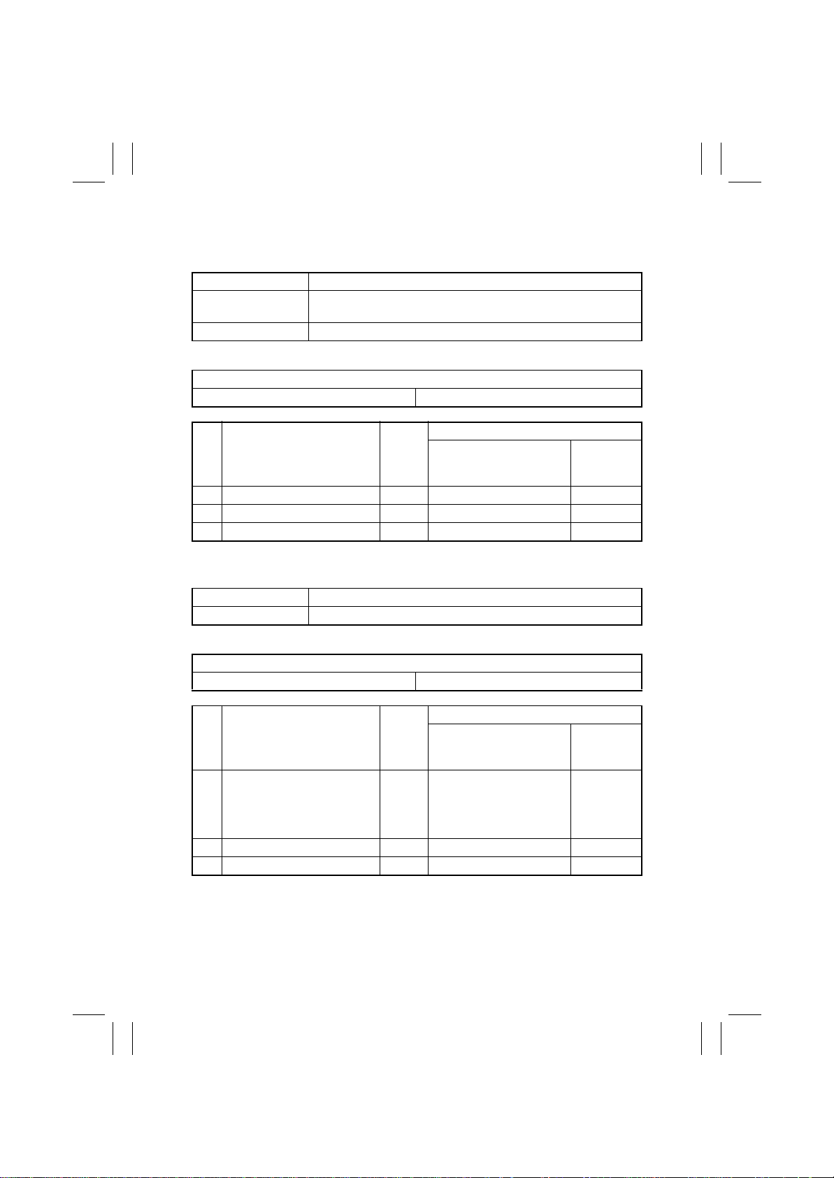
FrameMaker Ver.5.5E(PC) 8020/8031 TROUBLESHOOT ING
02.08.19
(64) C12C0: Hard Disk Error
(65) C12CB: Hard Disk Error
<Detection Timing>
Malfunction Code Description
C12C0
C12CB Data transfer from the hard disk is faulty.
<Action>
Image Control Board (PWB-F) Hard Disk
Step Action
1 Reinstall the hard disk. —— —
2 Change Hard Disk. —— —
3 Change PWB-F. —— —
Unable to communicate between the hard disk and Image Control
Board (PWB-F).
Relevant Electrical Parts
WIRING DIAGRAM
Ref.
Page
Control Signal
Location
(Electrical
Component)
(66) C12CC: Hard Disk Error
<Detection Timing>
Malfunction Code Description
C12CC Unformatted hard disk is connected.
<Action>
Relevant Electrical Parts
Image Control Board (PWB-F) Hard Disk
WIRING DIAGRAM
→
Ref.
Page
—— —
Control Signal
Step Action
Select “Tech. Rep. Mode”
“Machine Adjust”
1
Hard Disk Adjust”
Disk Format”
2 Change Hard Disk. —— —
3 Change PWB-F. —— —
→
“Memory/
→
“Hard
Location
(Electrical
Component)
T-62
Page 65
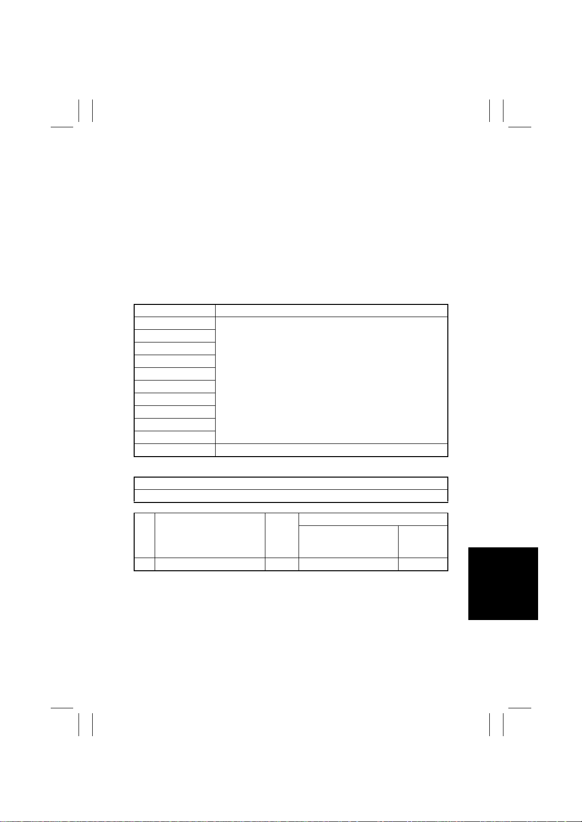
FrameMaker Ver.5.5E(PC) 8020/8031 TROUBLESHOOT ING
02.08.19
(67) C12C1: Hard Disk Error
(68) C12C2: Hard Disk Error
(69) C12C3: Hard Disk Error
(70) C12C4: Hard Disk Error
(71) C12C5: Hard Disk Error
(72) C12C6: Hard Disk Error
(73) C12C7: Hard Disk Error
(74) C12C8: Hard Disk Error
(75) C12C9: Hard Disk Error
(76) C12CA: Hard Disk Error
(77) C12CF: Hard Disk Error
<Detection Timing>
Malfunction Code Description
C12C1
C12C2
C12C2
C12C2
C12C2
C12C2
C12C2
C12C2
C12C2
C12C2
C12C2 A hard disk that falls outside the specifications is connected.
Hard disk is faulty.
<Action>
Relevant Electrical Parts
Hard Disk
WIRING DIAGRAM
Step Action
1 Change Hard Disk. —— —
Ref.
Page
Control Signal
Location
(Electrical
Component)
T-63
Page 66
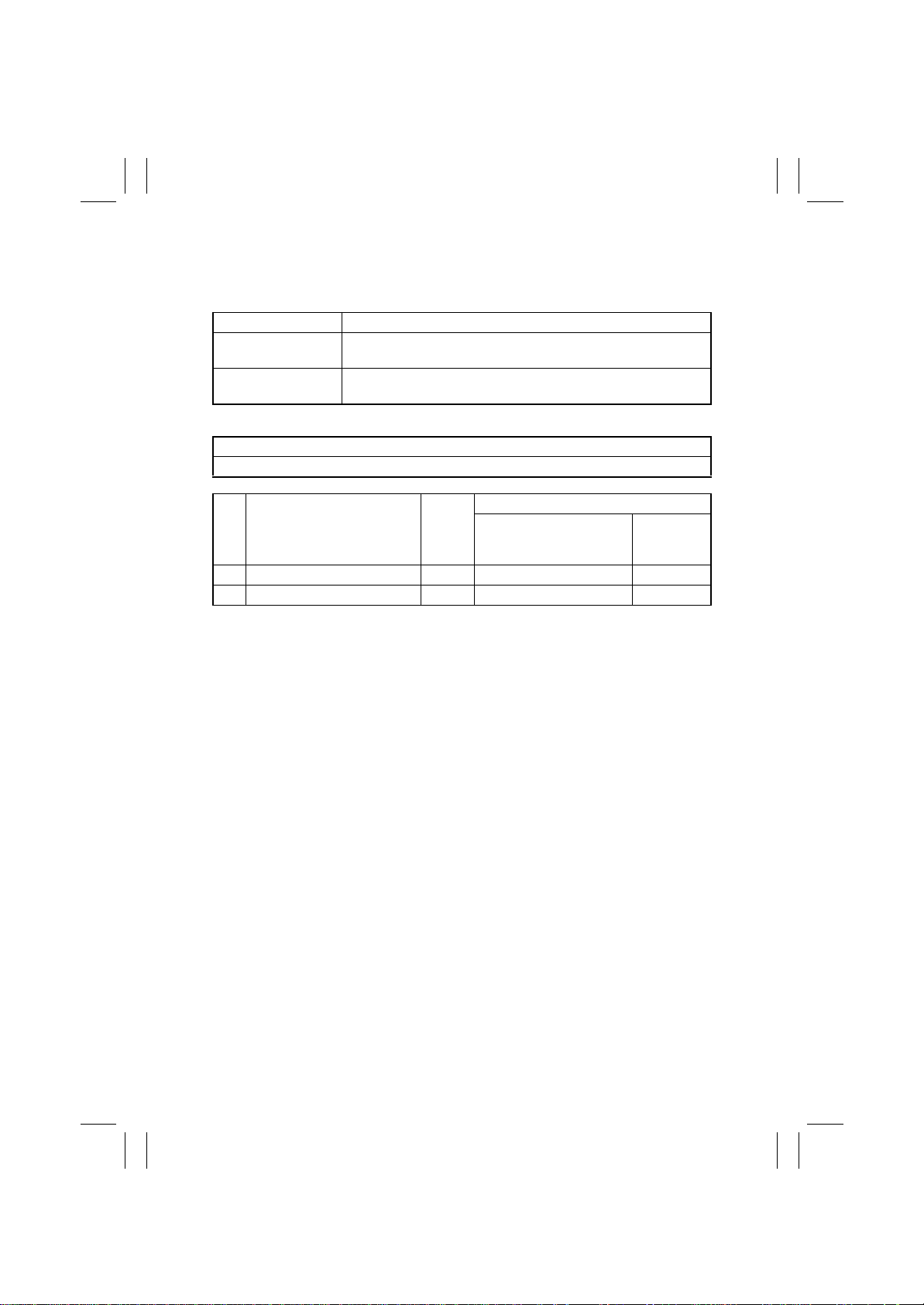
FrameMaker Ver.5.5E(PC) 8020/8031 TROUBLESHOOT ING
02.08.19
(78) C13C8: New Transfer Cleaner Unit resetting failure
(79) C13CA: New Fusing Unit resetting failure
<Detection Timing>
Malfunction Code Description
C13C8
C13CA
<Action>
IO Board (PWB-IO)
Step Action
1 Reinstall the unit. —— —
2 Change PWB-IO. —— —
A new installation is not canceled when a new Transfer Cleaner
Unit (Image Transfer Belt Unit) is installed.
A new installation is not canceled when a new Fusing Unit is
installed.
Relevant Electrical Parts
WIRING DIAGRAM
Ref.
Page
Control Signal
Location
(Electrical
Component)
T-64
Page 67
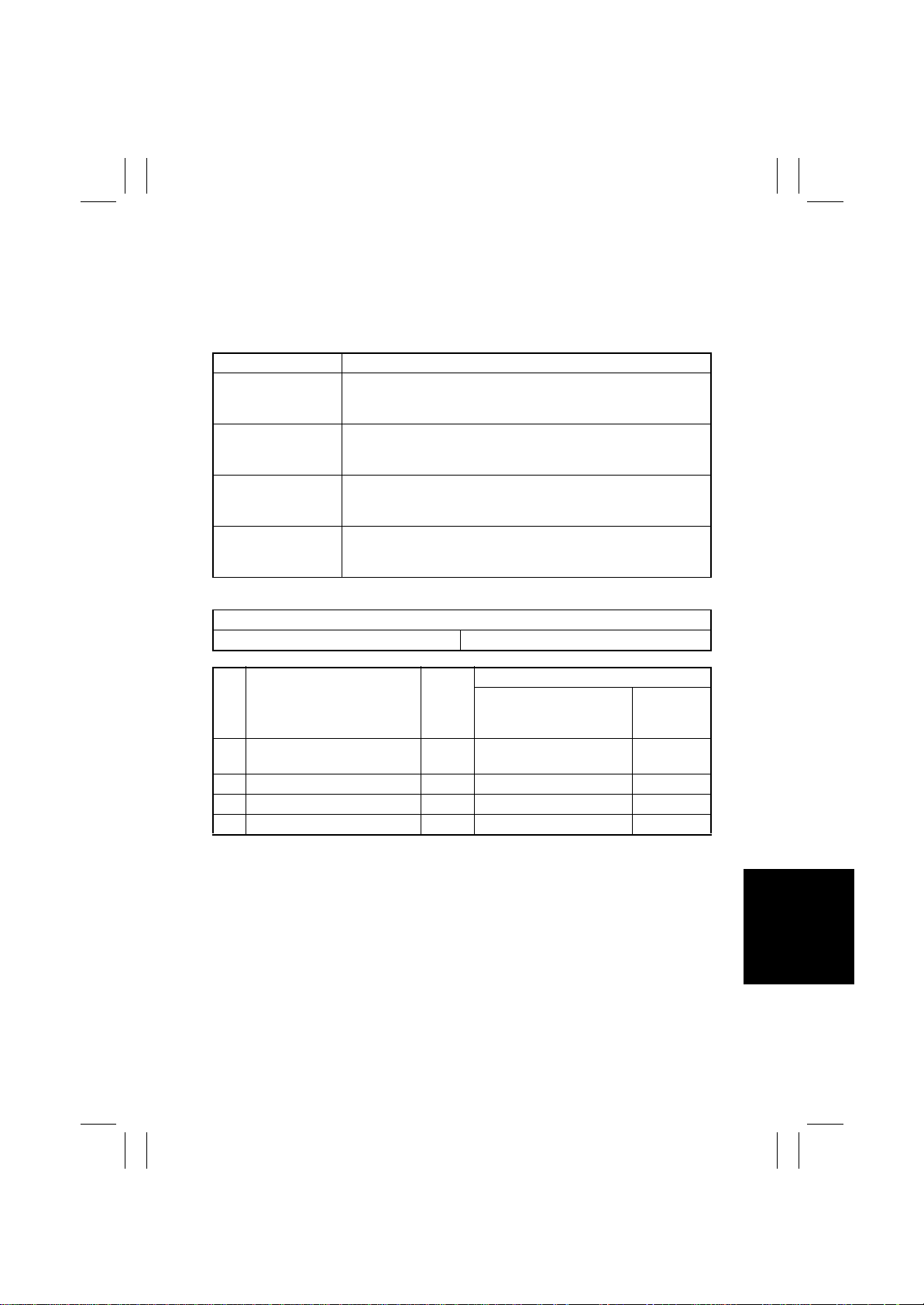
FrameMaker Ver.5.5E(PC) 8020/8031 TROUBLESHOOT ING
02.08.19
(80) C13D1: Cyan IU EEPROM access error
(81) C13D2: Magenta IU EEPROM access error
(82) C13D3: Yellow IU EEPROM access error
(83) C13D4: Black IU EEPROM access error
<Detection Timing>
Malfunction Code Description
C13D1
C13D2
C13D3
C13D4
<Action>
IO Board (PWB-IO) IU C/M/Y/Bk
Setting 1 “Start Flag” of GA register does not become ready even
after the lapse of a predetermined period of time after a cyan IU
EEPROM access control has been executed.
Setting 1 “Start Flag” of GA register does not become ready even
after the lapse of a predetermined period of time after a magenta
IU EEPROM access control has been executed.
Setting 1 “Start Flag” of GA register does not become ready even
after the lapse of a predetermined period of time after a yellow IU
EEPROM access control has been executed.
Setting 1 “Start Flag” of GA register does not become ready even
after the lapse of a predetermined period of time after a black IU
EEPROM access control has been executed.
Relevant Electrical Parts
WIRING DIAGRAM
Step Action
Clean the connection between
1
the IU and copier if dirty.
2 Reinstall IU C/M/Y/Bk. —— —
3 Change IU C/M/Y/Bk. —— —
4 Change PWB-IO. —— —
Ref.
Page
—— —
Control Signal
Location
(Electrical
Component)
T-65
Page 68
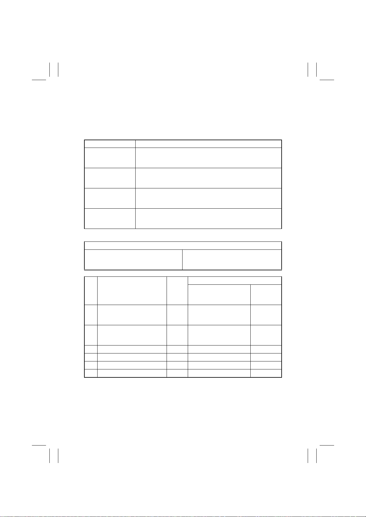
FrameMaker Ver.5.5E(PC) 8020/8031 TROUBLESHOOT ING
02.08.19
(84) C13D5: Cyan LPH correction data download failure
(85) C13D6: Magenta LPH correction data download failure
(86) C13D7: Yellow LPH correction data download failure
(87) C13D8: Black LPH correction data download failure
<Detection Timing>
Malfunction Code Description
C13D5
C13D6
C13D7
C13D8
<Action>
LPH C/M/Y/Bk LED Drive Board (PWB-LED)
A fault occurs while the LPH correction data is being downloaded
from the Cyan LPH EEPROM to the flash memory on PWB-PIC
when power is turned ON.
A fault occurs while the LPH correction data is being downloaded
from the Magenta LPH EEPROM to the flash memory on PWBPIC when power is turned ON.
A fault occurs while the LPH correction data is being downloaded
from the Yellow LPH EEPROM to the flash memory on PWB-PIC
when power is turned ON.
A fault occurs while the LPH correction data is being downloaded
from the Black LPH EEPROM to the flash memory on PWB-PIC
when power is turned ON.
Relevant Electrical Parts
PIC Board (PWB-PIC)
IO Board (PWB-IO)
WIRING DIAGRAM
Step Action
Correct the harness connec1
tion between LPH and PWB-
LED if faulty.
Correct the harness connec2
tion between PWB-LED and
PWB-PIC if faulty.
3 Change LPH C/M/Y/Bk. —— —
4 Change PWB-LED. —— —
5 Change PWB-IO. —— —
6 Change PWB-PIC. —— —
Ref.
Page
—— —
—— —
Control Signal
Location
(Electrical
Component)
T-66
Page 69
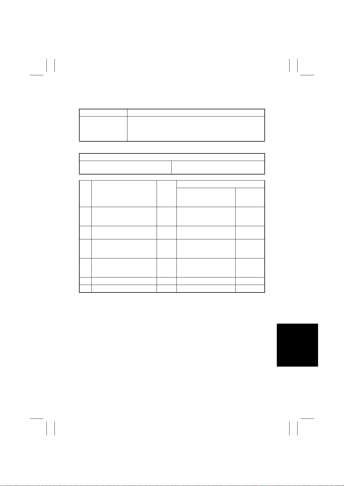
FrameMaker Ver.5.5E(PC) 8020/8031 TROUBLESHOOT ING
02.08.19
(88) C3310: CCD clamp/gain adjustment failure
<Detection Timing>
Malfunction Code Description
• The adjustment value is 0 or 255 during a CCD clamp adjust-
C3310
<Action>
Scanner Assy CCD Sensor Board (PWB-A)
Step Action
Correct the harness connec1
tion between PWB-A and
PWB-C if faulty.
Check for possible extraneous
2
light and correct as necessary.
Clean the lens, mirrors, CCD
3
surface, and shading sheet if
dirty.
Correct reflective mirror of the
4
Scanner if faulty, or change
Scanner.
5 Change PWB-A. —— —
6 Change PWB-C. —— —
ment.
• The peak value of the output data is 64 or less during a CCD
gain adjustment.
Relevant Electrical Parts
Image Processing Board (PWB-C)
WIRING DIAGRAM
Ref.
Page
—— —
—— —
—— —
—— —
Control Signal
Location
(Electrical
Component)
T-67
Page 70
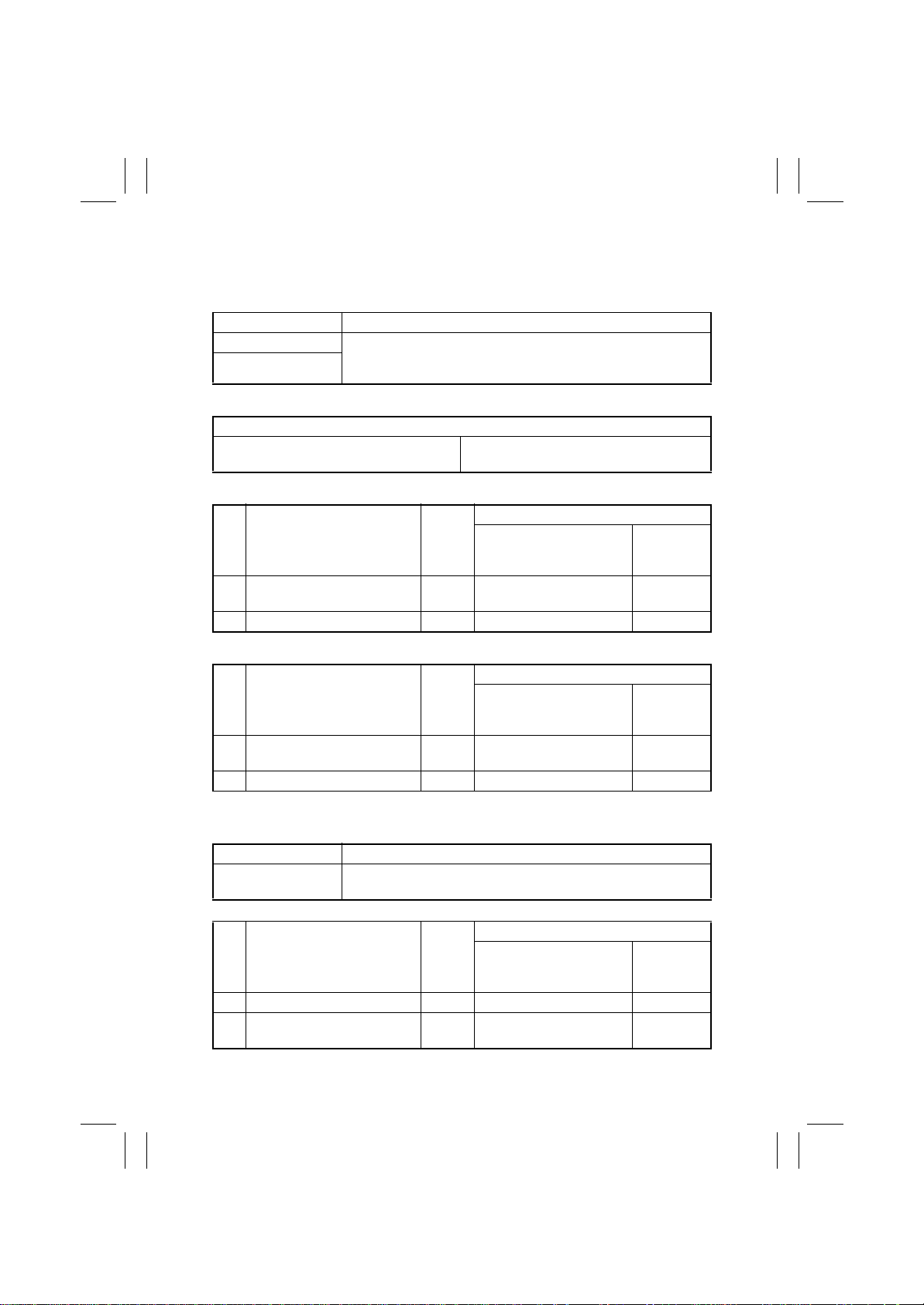
FrameMaker Ver.5.5E(PC) 8020/8031 TROUBLESHOOT ING
02.08.19
(89) C3700: IR Power Supply Cooling Fan Motor turning at abnormal timing
(90) C3710: IR Drive Board Cooling Fan Motor turning at abnormal timing
<Detection Timing>
Malfunction Code Description
C3700 A Lock signal is detected ten consecutive times when it is moniC3710
<Action>
IR Power Supply Cooling Fan Motor (M202)
IR Drive Board Cooling Fan Motor (M203)
✽
C3700
Step Action
1 M202 operation check T-3
2 Change PWB-C. —— —
tored at 0.01-sec. intervals during a period of time 2 sec. after the
output of a Fan Motor ON signal has been started.
Relevant Electrical Parts
Image Processing Board (PWB-C)
WIRING DIAGRAM
Ref.
Page
Control Signal
PWB-C PJ8C-18B(LOCK)
PWB-C PJ8C-17B(REM)
Location
(Electrical
Component)
19-G
✽
C3710
WIRING DIAGRAM
Step Action
1 M203 operation check T-3
2 Change PWB-C. —— —
(91) C3FFF: ROM contents fault detected upon start
<Detection Timing>
Malfunction Code Description
C3FFF
<Action>
Step Action
1 Check the ROM version. —— —
Rewrite firmware using the
2
memory card.
A fault is detected in the contents of ROM of MSC, IR, and PRT
when the copier is started.
Ref.
Page
Ref.
Page
—— —
Control Signal
PWB-C PJ8C-15B(LOCK)
PWB-C PJ8C-14B(REM)
WIRING DIAGRAM
Control Signal
Location
(Electrical
Component)
19-H
Location
(Electrical
Component)
T-68
Page 71
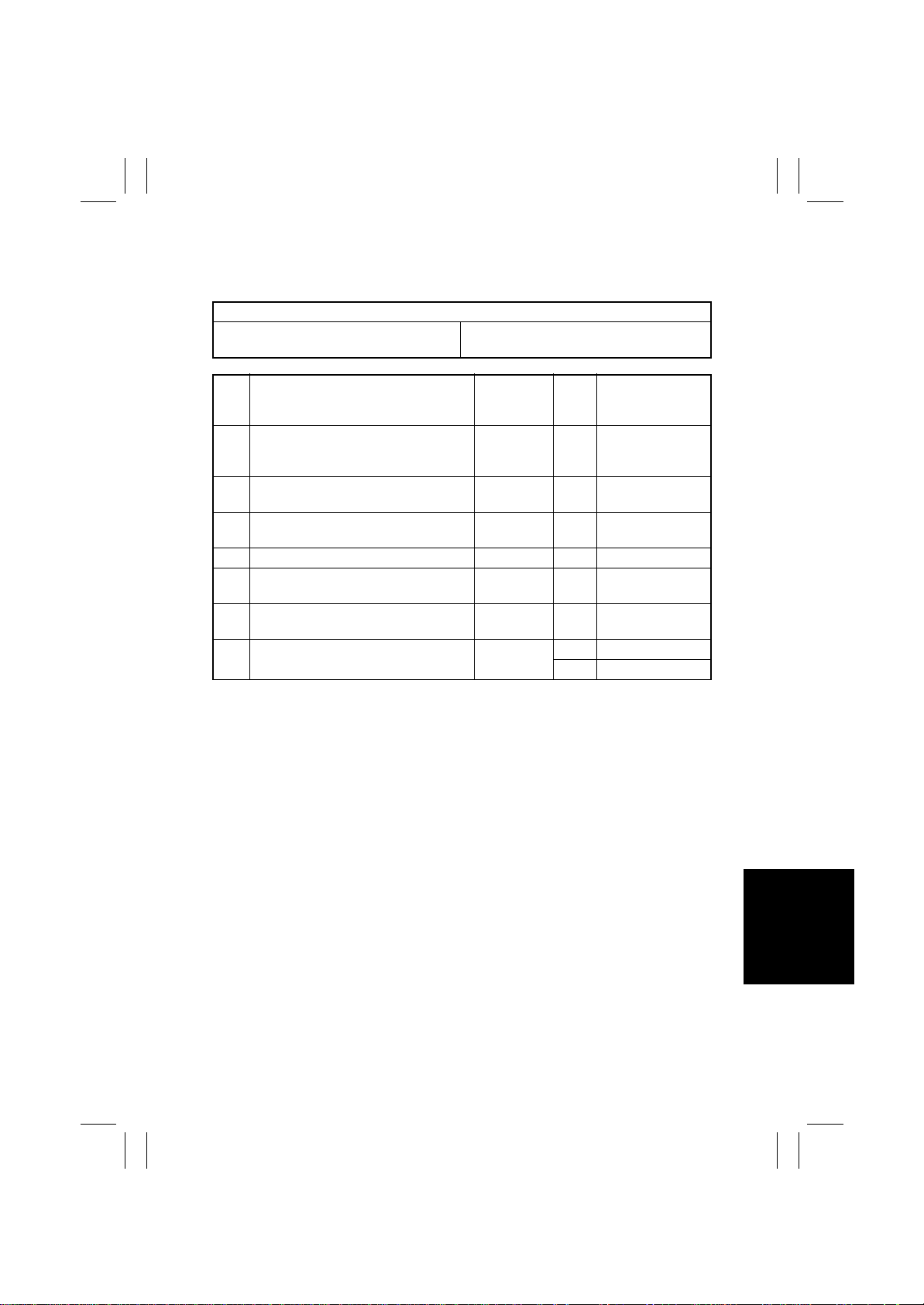
FrameMaker Ver.5.5E(PC) 8020/8031 TROUBLESHOOT ING
02.08.19
3-3. Power Supply-Related Malfunctions
(1) Copier is not energized at all.
Relevant Electrical Parts
IO Board (PWB-IO) DC Power Supply 1 (PU1)
DC Power Supply 2 (PU2)
Step Check Item
Is a power voltage supplied across
1
PJ3PU1-1 and 3 on PU1?
Are the fuses (F1 and F2) on PU1 con-
2
ducting?
Is a power voltage supplied across
3
CN1PU2-1 and 2 on PU2?
4 Is the fuse (F1) on PU2 conducting? — NO Change PU2.
Is DC5 V being output from CN2PU2-3
5
on PU2?
Is DC5 V being input to PJ15PU1-1 on
6
PU1?
Is DC5 V being input to PJ1IO-3 on the
7
IO Board?
WIRING
DIAGRAM
(Location)
30-H NO
— NO Change PU1.
30-F NO Change PU1.
31-F NO Change PU2.
28-F NO Change PU2.
14-E
Result Action
Check wiring
between the wall
outlet and PJ3PU1.
NO Change PU1.
YES Change PWB -I O.
T-69
Page 72
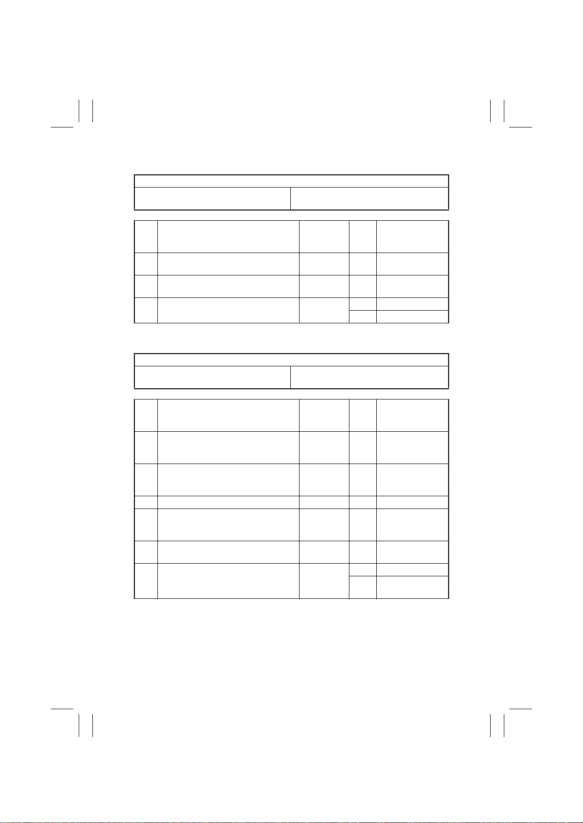
FrameMaker Ver.5.5E(PC) 8020/8031 TROUBLESHOOT ING
02.08.19
(2) Only the Power Supply Cooling Fan rotates.
Relevant Electrical Parts
PIC Board (PWB-PIC) DC Power Supply 1 (PU1)
DC Power Supply 2 (PU2)
Step Check Item
Is DC3.3 V being output from PJ9PU1-1
1
on PU1?
Is DC5 V being output from CN2PU2-2
2
on PU2?
Is DC3.3 V being input to PJ1PIC-1 on
3
PWB-PIC and DC5 V to PJ1PIC-3?
(3) Control panel indicat ors do not light.
Relevant Electrical Parts
Image Processing Board (PWB-C)
Control Panel (UN201)
Step Check Item
Is the I/F cable between the IR and
1
engine connected properly?
Is a power voltage being applied across
2
CN3PU201-1 and 2 on PU201?
3 Is the fuse (F1) on PU201 conducting? — NO Change PU201.
Is DC5.1 V being output from
4
CN2PU201-1 on PU201 and DC24 V
from CN2PU201-3?
Is PJ12C on PWB-C securely con-
5
nected?
Is CN12 on UN201 securely con-
6
nected?
WIRING
DIAGRAM
(Location)
29-F NO Change PU1.
31-F NO Change PU2.
32-C
DC Power Supply 3 (PU201)
WIRING
DIAGRAM
(Location)
— NO
22-H NO
22-H NO Change PU201.
26-E NO Reconnect .
24-F
Result Action
YES Change PWB-PIC.
NO Check the wiring.
Result Action
Reconnect or
change the I/F
cable.
Check the wiring
from the wall outlet
to CN3PU201-1/2.
NO Reconnect.
Change UN201.
YES
Change PWB-C.
T-70
Page 73
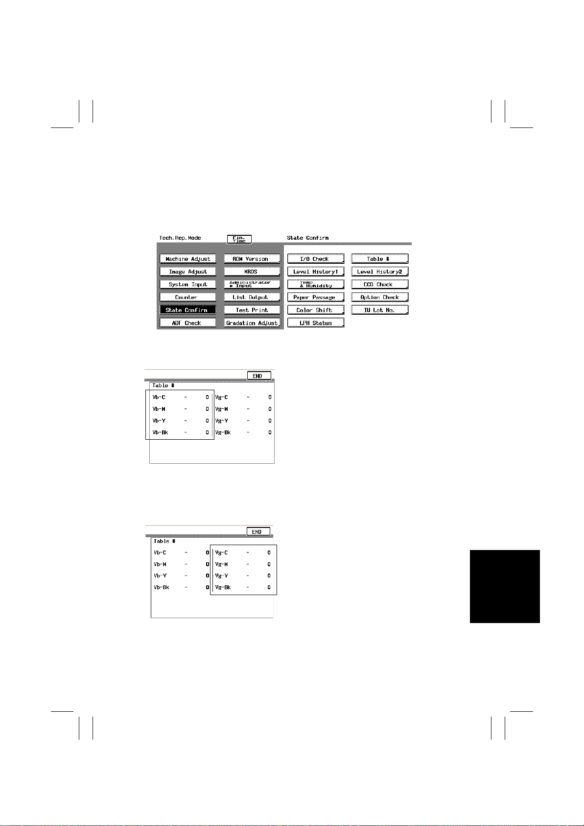
FrameMaker Ver.5.5E(PC) 8020/8031 TROUBLESHOOT ING
02.08.19
4. IMAGE QUALITY PROBLEMS
4-1. Descriptions of the “State Confirm” Function of Tech. Rep.
Mode Concerning Image Quality Problems
• As part of troubleshooting procedures, the numeric values set for “State Confirm” available from “Tech. Rep. Mode” can be used to isolate the cause of the image problem.
k4025T568CA
(1) Table #
Vb-C/-M/-Y/-Bk
• Shows the developing bias value of each
color of toner when an image is produced.
• Standard values: Around 400 V
✽
A correction is made to make the image
lighter when the numeric value is greater.
✽
A correction is made to make the image
darker when the numeric value is smaller.
4025T569CA
4025T569CA
<Relevant Components>
IU, High Voltage Unit (Devel oping Bias)
Vg-C/-M/-Y/-Bk
• Shows the grid voltage value of each color
of toner when an image is produced.
• Standard values: Around 550 V
✽
A correction is made to make the image
lighter when the numeric value is greater.
✽
A correction is made to make the image
darker when the numeric value is smaller.
<Relevant Components>
IU, High Voltage Unit (Devel oping Bias)
T-71
Page 74
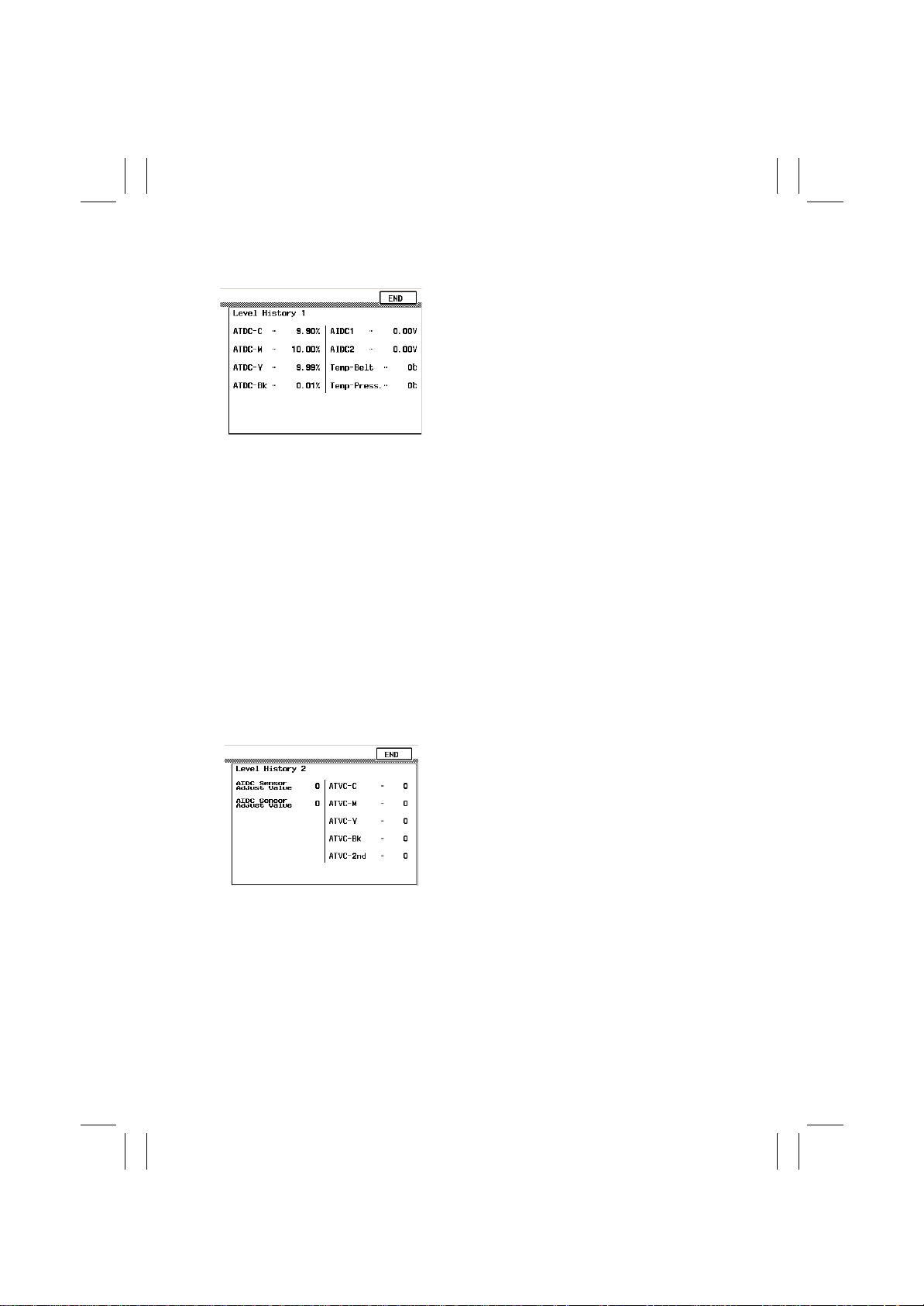
FrameMaker Ver.5.5E(PC) 8020/8031 TROUBLESHOOT ING
02.08.19
(2) Level History 1
ATDC-C/-M/-Y/-Bk
• Shows the T/C ratio (in 0.01 % increments).
• Standard value: 8
<Relevant Components>
LPH Unit, ATDC Sensor Bk
ATDC1/2
• Shows the AIDC bare surface output reading
taken last (in 0.01 V increments).
4025T570CA
• It should normally be around 4.2 V.
• The output range is 0 V to 5 V.
<“Reading taken last” means>
• During the last image stabilization sequence.
• When the Start key is pressed, the output value
is displayed while a test print is being produced.
<Relevant Components>
AIDC Sensor, Transfer Belt Unit
Temp-Belt/Press.
• Shows the temperature of the Heating Roller
(Temp-Belt) and the Fusing Pressure Roller
(Temp-Press.) (in 5
±
–3 %
°
C increments).
(3) Level History 2
4025T571CA
<Relevant Components>
Fusing Unit
AIDC Sensor Adjust Value
• Shows the AIDC intensity adjustment value.
• It should normally be around 50 and can range
from 0 to 255.
• The value becomes greater as the T r ansfer Belt
Unit has been used more.
<Relevant Components>
AIDC Sensor, Transfer Belt Unit
ATVC-C/-M/-Y/-Bk/2nd
• Shows the latest ATVC level (which varies
according to the paper type).
• 400 V to 3000 V (A TVC-C/-M/-Y/-Bk)
• 300 V to 5000 V (ATVC-2nd)
<Relevant Components>
Transfer Belt Unit, High Voltage Unit (Image
Transfer, Neutralizing)
T-72
Page 75
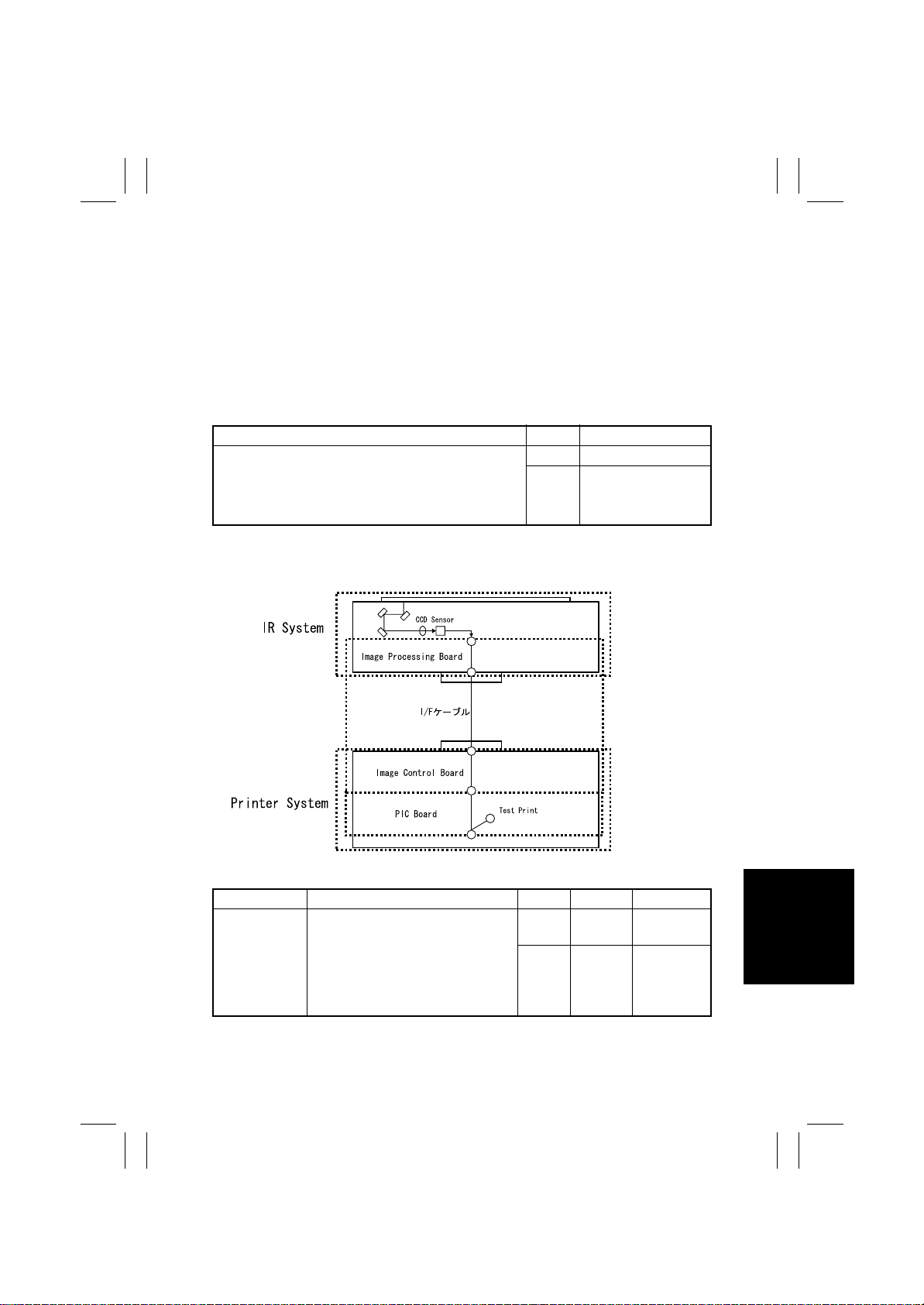
FrameMaker Ver.5.5E(PC) 8020/8031 TROUBLESHOOT ING
02.08.19
4-2. Troubleshooting Image Quality Problems
• This chapter is divided into two parts: “Initial Check Items” and “Tr oubleshooting Procedure by a Particular Image Quality Problem.”
• When an image quality problem occurs, first go through the “Initial Check Items” and, if
the cause is yet to be identified, go to “Troubleshooting Procedure by a Particular Image
Quality Problem.”
4-3. Initial Check Items
1. Check first to see if image data is properly transmitted between IR and memory, and
between memory and printer.
Action Result Next Step
OK Initial check item (2)
Enter the Tech. Rep. Mode, select “Machine Adjust”
→
“Memory/Hard Disk Adjust ”
and select and carry out “IR
→
PRT” checks.
ory
2. Let the copier produce a test print and determine whether the image problem is attribut-
able to the IR or printer system.
“Memory Bus Check,”
→
Memory” and “Mem-
→
☞
NG
T- 58, 59
(action as instructed)
4025T575CA
• Evaluation Procedure
Image Problem Action Result Cause Next Step
Lines, bands
From “T ech. Rep. Mode,” select “Test
→
Print”
GLE”
“C
and produce a test print. Is image
problem evident?
“Halftone Pattern” → “SIN-
→
“HYPER” → “Gradation” →
→M→Y→
Bk” → “Density 64,”
YES Printer
NO IR
Initial check
item (3)
☞
T-75
T-73
Page 76
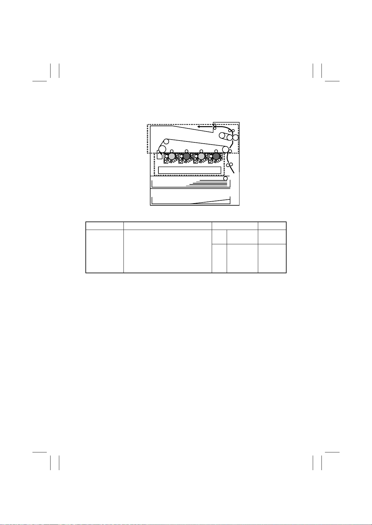
FrameMaker Ver.5.5E(PC) 8020/8031 TROUBLESHOOT ING
02.08.19
3. If the printer is responsible for the image problem, let the copier produce a test print and
determine whether the image problem occurs in a specific single color or four colors.
4 colors
Mono color
4004T008CA
• Evaluation Procedure
Image Problem Action Result Next Step
Lines, bands
From “Tech. Rep. Mode,” select “Tes t
→
Print”
GLE”
“C
produce a test print. Is image problem
evident in each of all four colors?
“Halftone Pattern” → “SIN-
→
“HYPER”→ “Gradation”→
→M→Y→
Bk”→ “Density 64,” and
YES
NO
Printer,
4 colors
Printer,
single color
☞
☞
T-104
T-8 8
T-74
Page 77
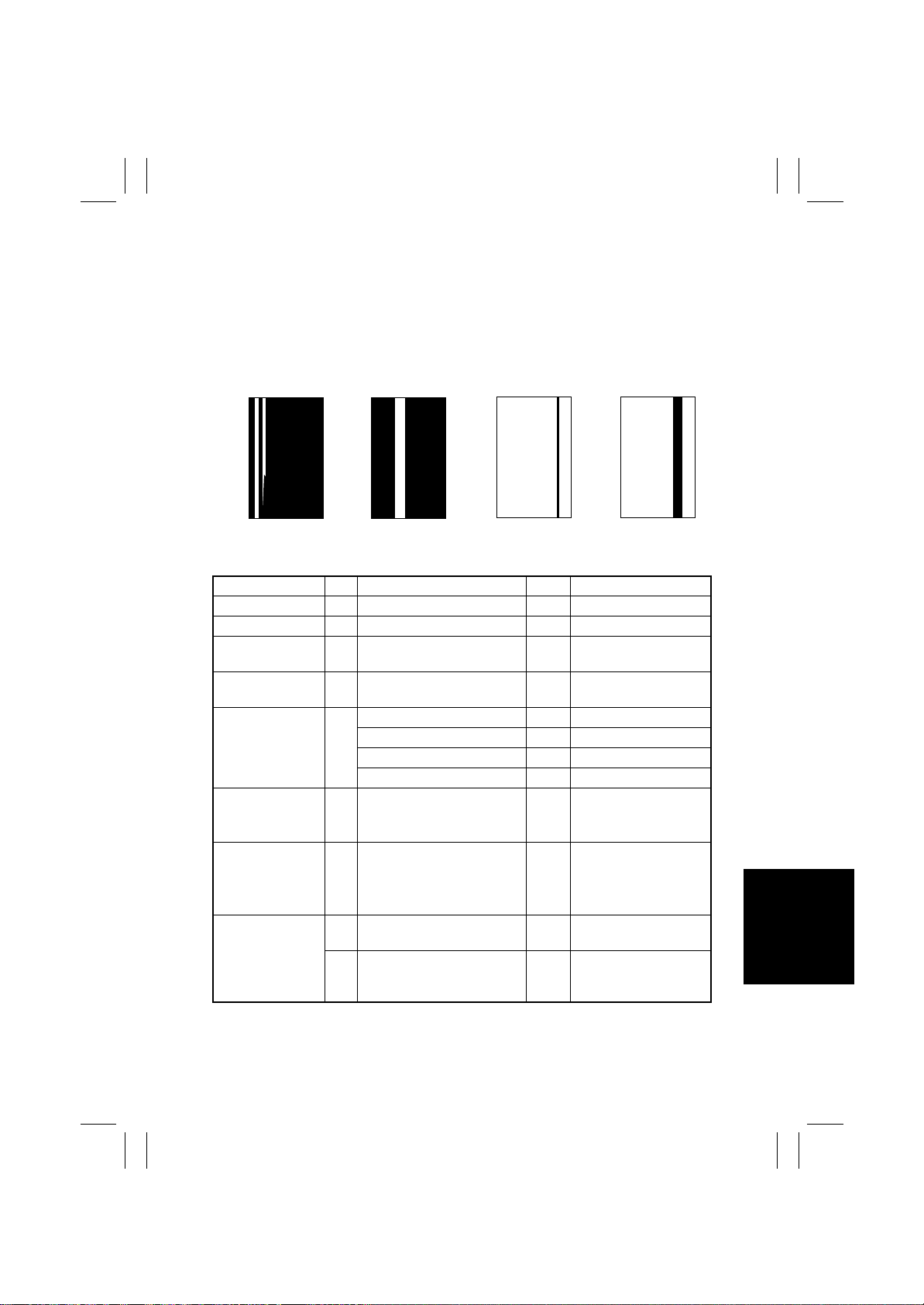
FrameMaker Ver.5.5E(PC) 8020/8031 TROUBLESHOOT ING
02.08.19
4-4. Troubleshooting Procedure by a P articular Image Quality
Problem
(1) IR System: white lines in FD, white bands in FD, colored lines in FD, and col-
ored bands in FD
<Typical Faulty Images>
White lines in FD White bands in FD Color bands in FDColor lines in FD
4011T015AA
<Troubleshooting Procedure>
Section St ep Check Item Result Action
Original 1 Original is damaged or dirty. YES Change original.
Original Cover 2 Original Pad is dirty. YES Clean.
Original Glass 3 Original Glass is dirty. YES Wipe the surface clean
Shading sheet 4 Shading sheet is dirty. YES Wipe the surface clean
Mirror, lens, Exposure Lamp, and
reflectors
System Input
Serial # Input
(Tech. Rep. Mode)
Machine Adjust
IR Area
→
Left Image
(Tech. Rep. Mode)
IR 8 The white lines/bands or col-
→
5 Mirror is dirty. YES Clean.
6 The IR serial number has
7 The adjustment value for Left
→
9 The white lines/bands or col-
4011T020AA 4011T017AA 4011T023AA
with a soft cloth.
with a soft cloth.
Lens is dirty. YES Clean.
Exposure Lamp is dirty. YES Clean.
Reflectors are dirty. YES Clean.
NO Enter correctly.
been correctly entered.
Readjust.
Image falls within the specified range.
YES Change Scanner Assy.
ored lines/bands are blurry.
YES Change CCD Unit.
ored lines/bands are clear
and distinct.
T-75
Page 78
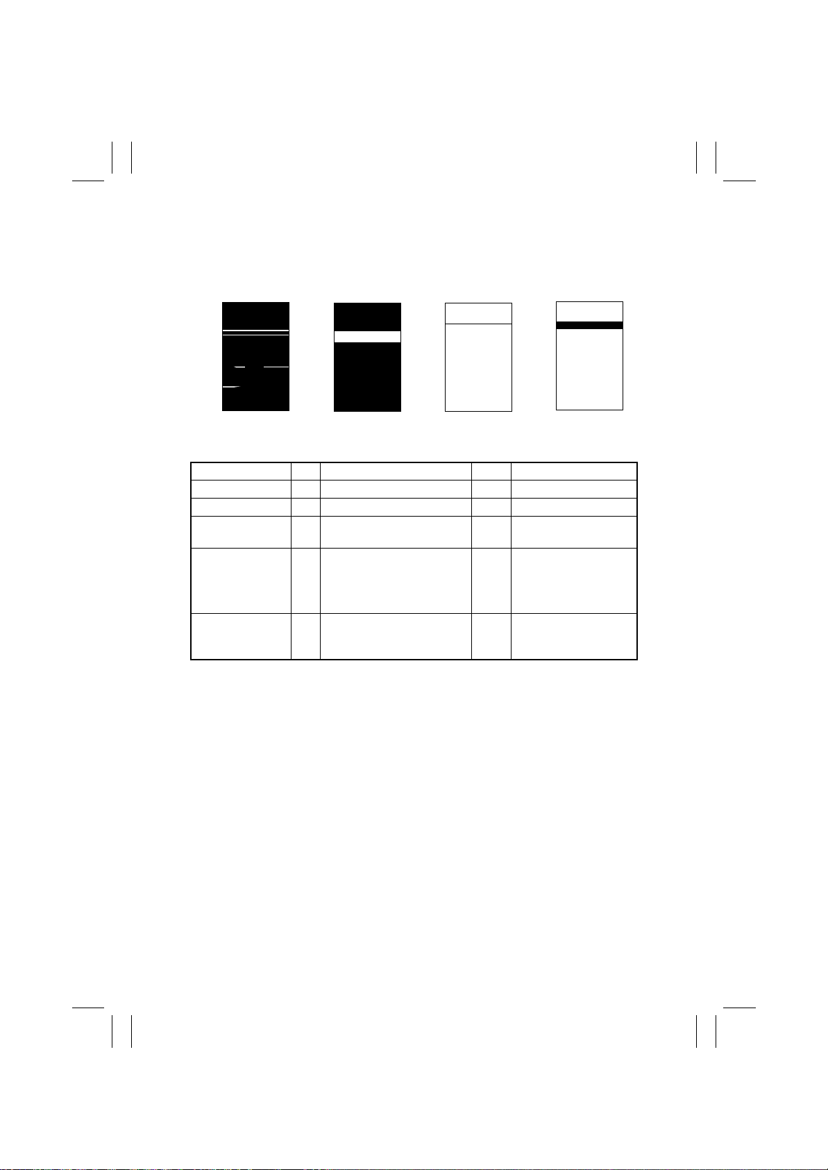
FrameMaker Ver.5.5E(PC) 8020/8031 TROUBLESHOOT ING
02.08.19
(2) IR System: white lines in CD, white bands in CD, colored lines in CD, and col-
ored bands in CD
<Typical Faulty Images>
White lines in CD W hite bands in CD Color bands in CDColor lines in CD
4011T016AA
<Troubleshooting Procedure>
Section St ep Check Item Result Action
Original 1 Original is damaged or dirty. YES Change original.
Original Cover 2 Original Pad is dirty. YES Clean.
Original Glass 3 Original Glass is dirty. YES Wipe the surface clean
4 The adjustment value for Top
→
Machine Adjust
IR Area
→
Top Image
(Tech. Rep. Mode)
5 The problem has been elimi-
4011T021AA 4011T018AA 4011T022AA
with a soft cloth.
Image falls within the specified range.
nated through the checks of
steps up to 4.
Readjust.
NO Change Scanner Assy.
Change CCD Unit.
T-76
Page 79
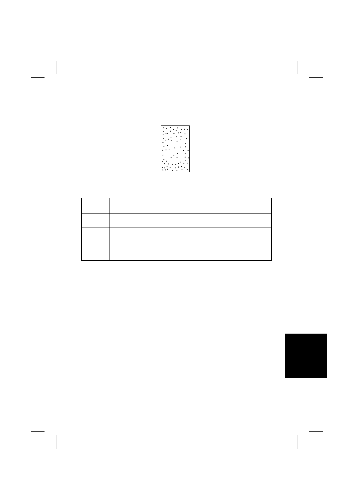
FrameMaker Ver.5.5E(PC) 8020/8031 TROUBLESHOOT ING
02.08.19
(3) IR System: color spots
<Typical Faulty Image>
C F
4011T027AA
<Troubleshooting Procedure>
Section Step Check Item Result Action
Original 1 Original is damaged or dirty. YES Change original.
Original
Cover
Original
Glass
2 Original Pad is dirty. YES Clean.
3 Original Glass is dirty . YES Wipe the surface clean with a
4 The problem has been elimi-
nated through the checks of
steps up to 3.
soft cloth.
NO Change Scanner Assy.
Change CCD Unit.
T-77
Page 80
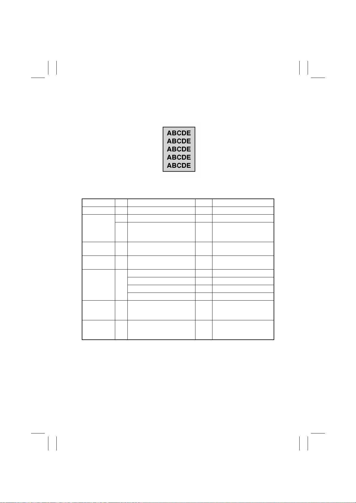
FrameMaker Ver.5.5E(PC) 8020/8031 TROUBLESHOOT ING
02.08.19
(4) IR System: fog
<Typical Faulty Image>
4011T004AA
<Troubleshooting Procedure>
Section Step Check Item Result Action
Original 1 Or iginal is damaged or dirty. YES Change original.
Original Cover 2 Original Pad is dirty. YES Clean.
3 Original Cover does not lie flat. YES Change Original Cover if it
Original Glass 4 Original Glass is dirty. YES Wipe the surface clean with
Shading sheet 5 Shading sheet is dirty. YES Wipe the surface clean with
Mirror, lens,
Exposure
Lamp, and
reflectors
Photo/Density 7 The problem is eliminated
6 Mirror is dirty. YES Clean.
Lens is dirty. YES Clean.
Exposure Lamp is dirty. YES Clean.
Reflectors are dirty. YES Clean.
when the image is produced in
the Manual exposure setting.
8 The problem has been elimi-
nated through the checks of
steps up to 7.
is deformed or hinges are
broken.
a soft cloth.
a soft cloth.
NO Try another exposure level
in Manual.
NO Change Scanner Assy.
Change CCD Unit.
T-78
Page 81
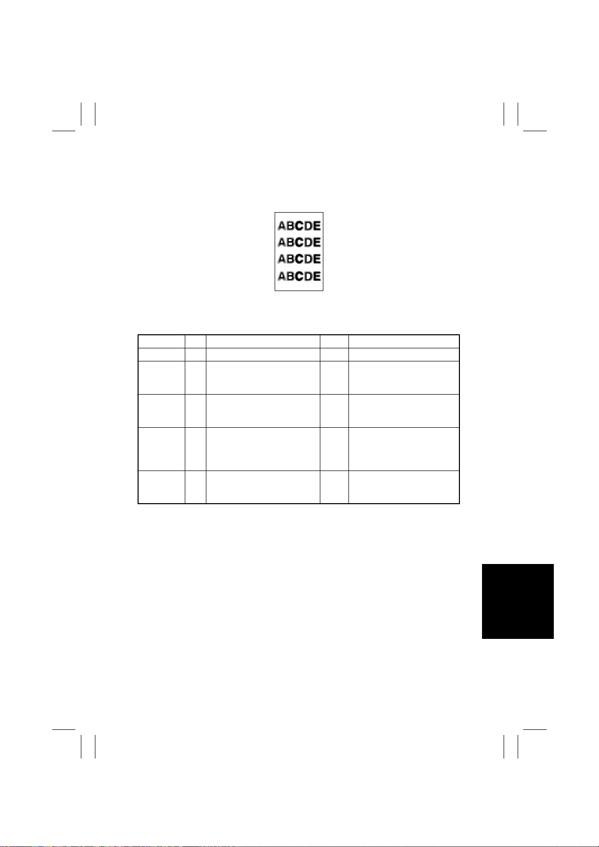
FrameMaker Ver.5.5E(PC) 8020/8031 TROUBLESHOOT ING
02.08.19
(5) IR System: blurred image, blotchy image
<Typical Faulty Image>
4011T046AA
<Troubleshooting Procedure>
Section Step Check Item Result Action
Original 1 Original does not lie flat. Y ES Change original.
Original
Cover
Original
Glass
IR 4 Scanner is not aligned with the
2 Original Cover does not lie flat. YES Change Original Cover if it is
deformed or hinges are broken.
3 Original Glass tilts. YES Position Original Glass cor-
rectly. Check original loading
position.
YES Perform “Focus Positioning of
2nd/3rd Mirrors Carriage.
5 The problem has been elimi-
nated through the checks of
steps up to 4.
the Scanner and 2nd/3rd Mirrors Carriage” and “Scanner
Position Adjustment.”
NO Change Scanner Assy.
Change CCD Unit.
T-79
Page 82
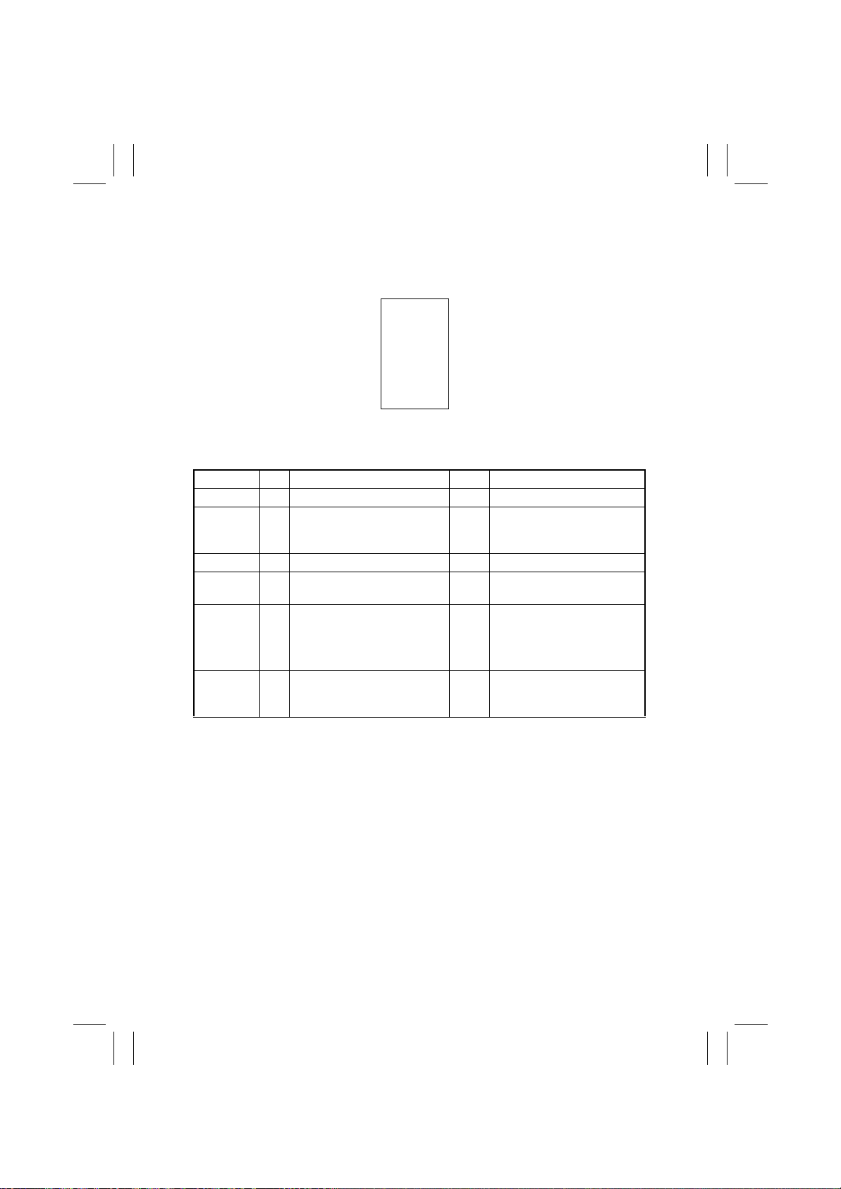
FrameMaker Ver.5.5E(PC) 8020/8031 TROUBLESHOOT ING
02.08.19
(6) IR System: incorrect color image registration, sync shift (lines in CD)
<Typical Faulty Image>
C F
C F
4011T039AA
<Troubleshooting Procedure>
Section Step Check Item Result Action
Original 1 Original does not lie flat. Y ES Change original.
Original
Cover
Slide rails 3 Foreign matter on rails. YES Clean and apply lubricant.
Drive
Cables
Scanner
Assy
2 Original Cover does not lie flat. YES Change Original Cover if it is
deformed or hinges are broken.
4 Cable kinks or is damaged. YES Correct or change.
5 Scanner moves smoothly. NO Adjust the Scanner Motor tim-
ing belt.
→
Change bushing.
→
Change Scanner Motor.
6 The problem has been elimi-
nated through the checks of
steps up to 5.
NO Change CCD Unit.
T-80
Page 83
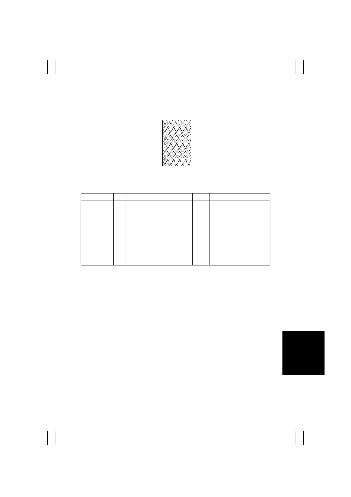
FrameMaker Ver.5.5E(PC) 8020/8031 TROUBLESHOOT ING
02.08.19
(7) IR System: moire
<Typical Faulty Image>
4011T040AA
<Troubleshooting Procedure>
Section Step Check Item Result Action
Original 1 Moire distortions recur even
after the orientation of original
has been changed.
Photo/Density 2 Moire distortions recur even
after the original mode has
been changed.
3 The problem has been elimi-
nated through the checks of
steps up to 2.
YES Change th e original mode
(select one other than that
resulted in moire).
YES Select “Gradation” (mode
optimized for gradation) or
“Resolution” (that optimized
for resolution).
NO Change the zoom ratio.
T-81
Page 84
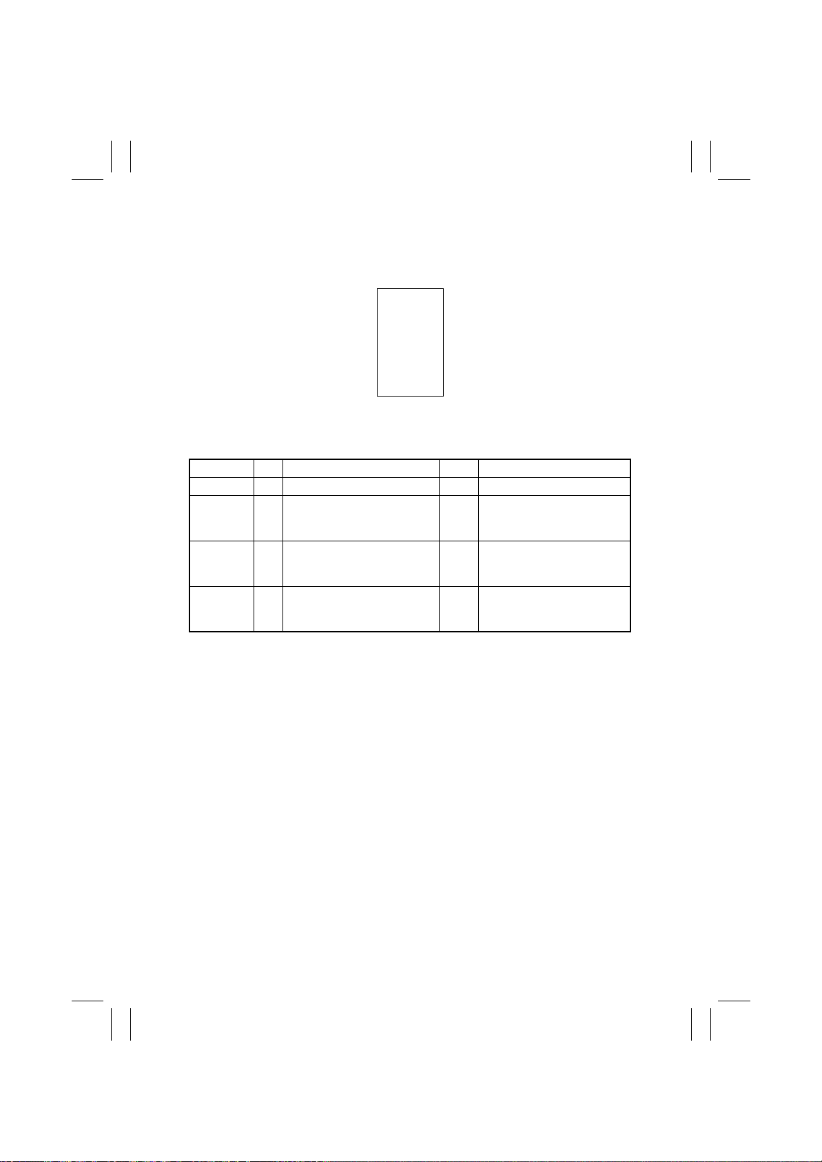
FrameMaker Ver.5.5E(PC) 8020/8031 TROUBLESHOOT ING
02.08.19
(8) IR System: skewed image
<Typical Faulty Image>
C F
4011T048AA
<Troubleshooting Procedure>
Section Step Check Item Result Action
Original 1 Original is skew. YES Reposition original.
Original
Glass
2nd/3rd
Mirrors Carriage
2 Original Glass is in positive
contact with the flat spring
without being tilt.
3 Scanner Assy is not properly
aligned with 2nd/3rd Mirrors
Carriage.
4 The problem has been elimi-
nated through the checks of
steps up to 3.
NO Reinstall the glass. Check the
original loading position.
YES Readjust with the Scanner/
Mirrors Carriage Positioning
Jigs.
NO Change Scanner Assy.
Change CCD Unit.
T-82
Page 85
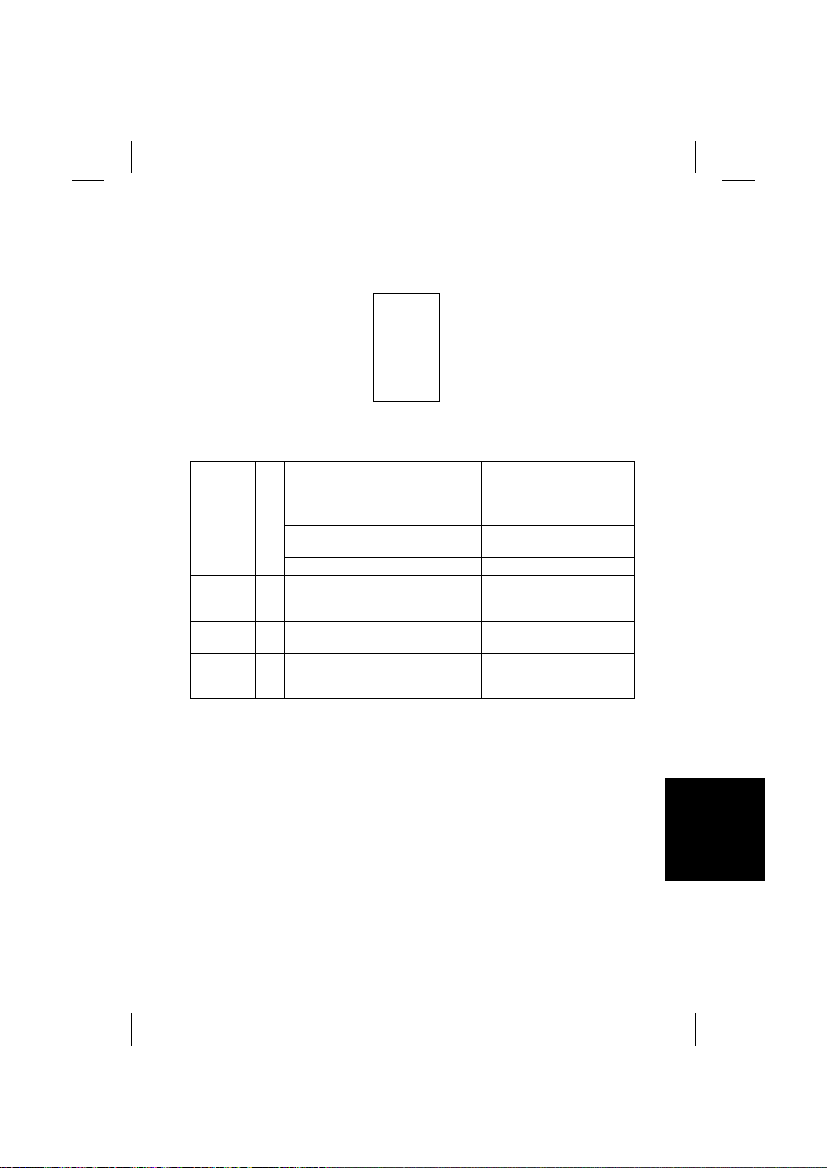
FrameMaker Ver.5.5E(PC) 8020/8031 TROUBLESHOOT ING
02.08.19
(9) IR System: distorted image
<Typical Faulty Image>
ABCDE
ABCDE
ABCDE
ABCDE
ABCDE
4011T045AA
<Troubleshooting Procedure>
Section Step Check Item Result Action
Installation 1 IR is installed on a level sur-
2nd/3rd
Mirrors Carriage
Scanner
Motor
face if mounted without any
rack.
Rack is installed on a level surface.
Rack is tilt with a lot of play. YES Adjust rack leg height.
2 Scanner Assy is not properly
aligned with 2nd/3rd Mirrors
Carriage.
3 Scanner Motor turns smoothly. NO Change belt.
4 The problem has been elimi-
nated through the checks of
steps up to 3.
NO Reinstall.
NO Reinstall.
YES Readjust with the Scanner/
Mirrors Carriage Positioning
Jigs.
Change Scanner Motor.
NO Change Scanner Assy.
Change CCD Unit.
T-83
Page 86
FrameMaker Ver.5.5E(PC) 8020/8031 TROUBLESHOOT ING
02.08.19
(10) IR System: low image density, rough image
<Typical Faulty Image>
4011T003AA
<Troubleshooting Procedure>
Section Step Check Item Result Action
Original 1 Original sticks to Original
Original
Glass
Shading
sheet
Mirror, lens,
Exposure
Lamp, and
reflectors
Glass.
2 Original Glass is dirty . YES Wipe the surface clean with a
3 Shading sheet is dirty. YES Wipe the surface clean with a
4 Mirror is dirty. YES Clean.
5 Lens is dirty. YES Clean.
6 Exposure Lamp is dirty. YES Clean.
7 Reflectors are dirty. YES Clean.
8 The problem has been elimi-
nated through the check of
step 7.
YES Reposition original.
soft cloth.
soft cloth.
NO Clean Exposure Lamp.
→
Change Scanner Assy.
→
Change CCD Unit.
T-84
Page 87
FrameMaker Ver.5.5E(PC) 8020/8031 TROUBLESHOOT ING
02.08.19
(11) IR System: defective ACS
<Typical Faulty Image>
Colored Area of Original
CF
ABCDE
ABCDE
ABCDE
ABCDE
Black-and-White Area of
Original
ABCDE
4011T052AA
<Troubleshooting Procedure>
Section Step Check Item Result Ac tion
ACS Judgement Level
Adjust (User’s
Choice 2)
1 The problem persists even
after the ACS Determination
Level Adjust function has
been changed.
YES Change the original loading
direction. Make manual settings according to the type of
original. (If the original contains a colored area in one of
its corners, the copier may fail
to properly detect the colored
area.)
T-85
Page 88
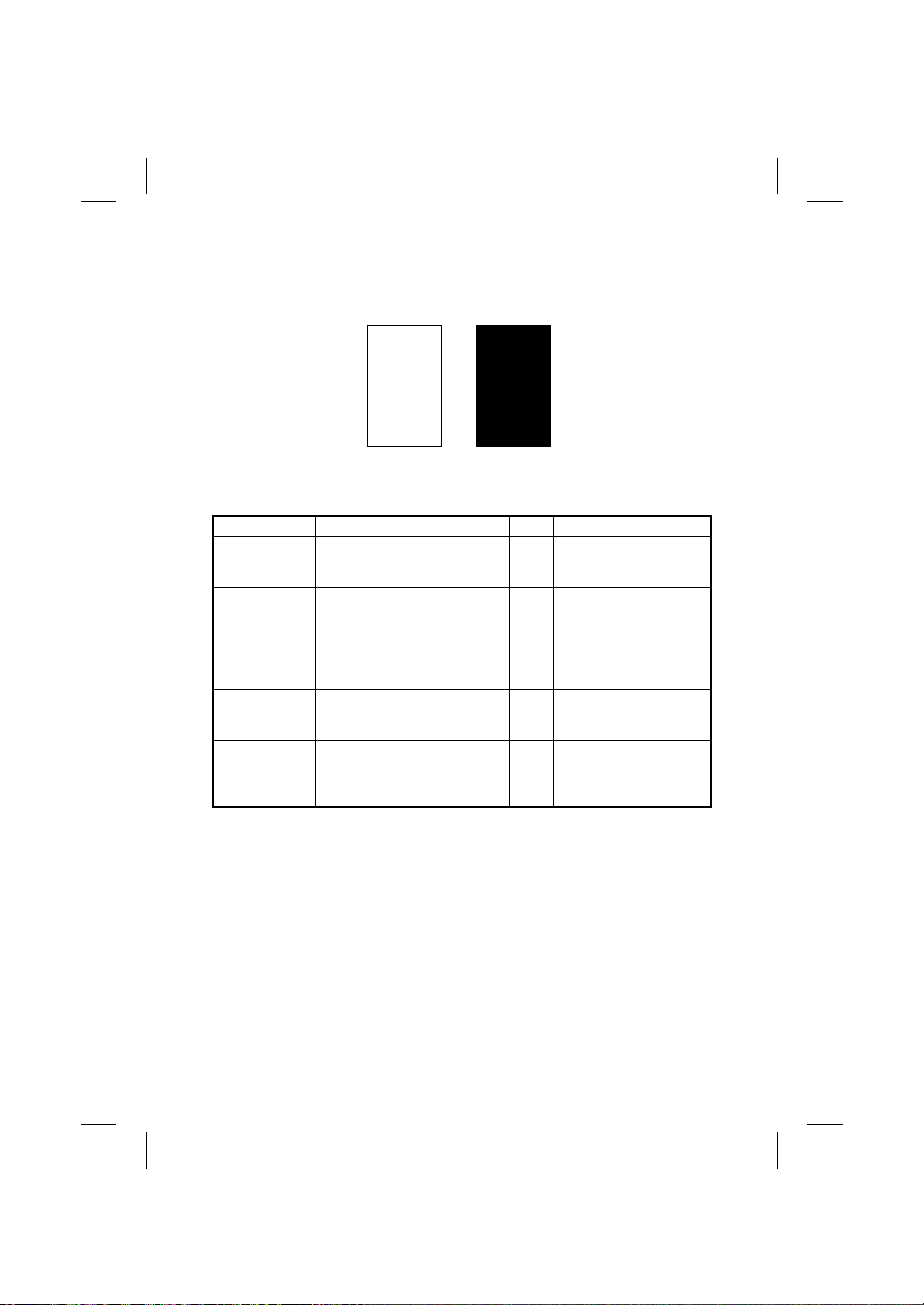
FrameMaker Ver.5.5E(PC) 8020/8031 TROUBLESHOOT ING
02.08.19
(12) IR System: blank copy, black copy
<Typical Faulty Images>
Blank copy Black copy
4011T036AA
4011T035AA
<Troubleshooting Procedure>
Section Step Check Item Result Action
Cable
connecting IR
1 Connector is connected
properly with no pins bent.
NO Reconnect.
and printer
Image
Processing
Board
2 Connectors on the Image
Processing Board are connected properly.
NO Reconnect.
(PWB-C)
CCD Unit 3 Connectors of the CCD Unit
NO Reconnect.
are connected properly.
Test Print
(Tech.Rep.Mode)
4 The problem is eliminated
as checked with the image
NO Change I/F connection
cable.
on a test pattern produced.
Image
Processing
Board
5 The problem is eliminated
after the I/F connection
cable has been changed.
NO Change Image Processing
Board.
(PWB-C)
T-86
Page 89
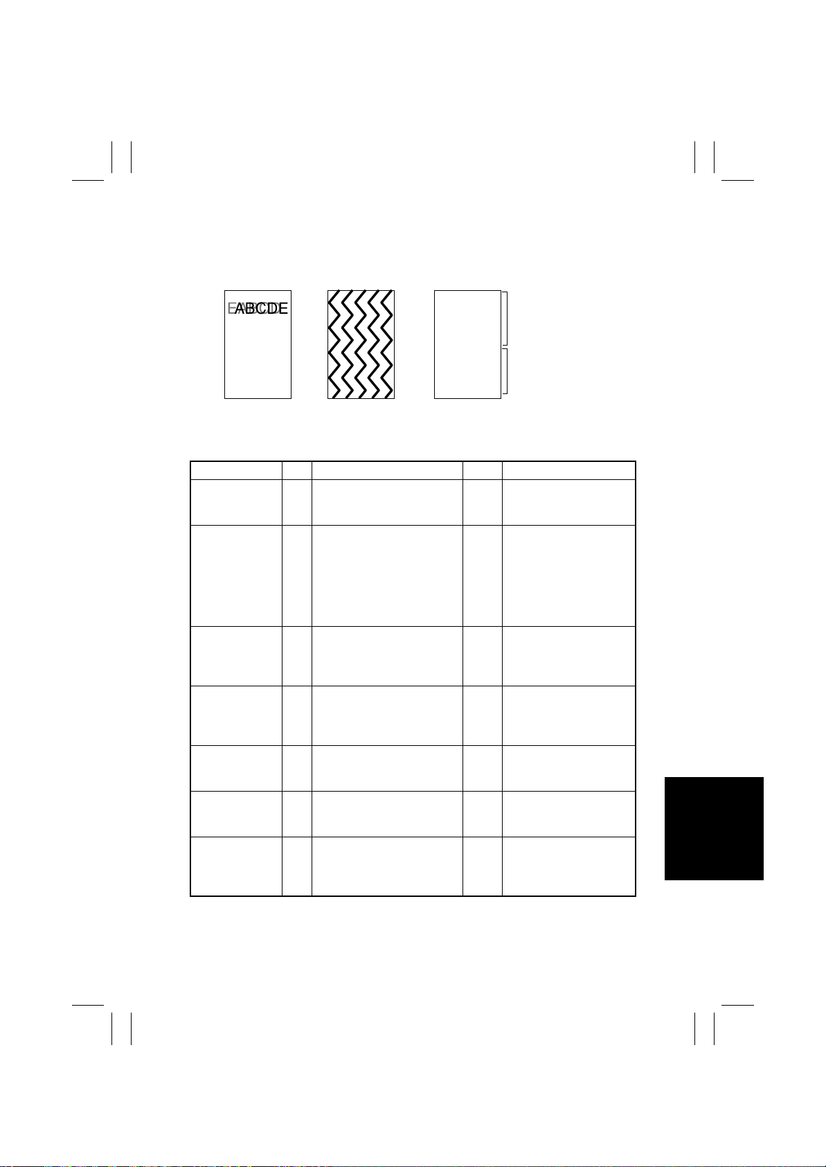
FrameMaker Ver.5.5E(PC) 8020/8031 TROUBLESHOOT ING
CF
ABCDE
ABCDE
ABCDE
02.08.19
(13) IR System: abnormal image
<Typical Faulty Images>
ABCDE
Data on previous page
ABCDE
ABCDE
ABCDE
Data on current page
ABCDE
4011T053AA
<Troubleshooting Procedure>
Section Step Check Item Result Action
Cable
connecting
IR and printer
Connection cable
between controller
I/F board and
Image
Control Board
(PWB-F)
Image
Processing
Board
(PWB-C)
Image
Processing Interface Board
(PWB-B)
Image Control
Board
(PWB-F)
Test Print
(Tech.Rep.Mode)
Image
Processing
Board
(PWB-C)
1 Connector is connected prop-
erly with no pins bent.
2 Connector is connected prop-
erly with no pins bent.
3 Connectors on the Image
Processing Board are connected properly.
4 Connectors on the Image
Processing Board are connected properly.
5 Data on previous page is
mixed with data on current
page.
6 The problem is eliminated as
checked with the image on a
test pattern produced.
7 The problem is eliminated
after the interface connection
cable has been changed.
4011T063AA4004T010AB
NO Reconnect.
NO Reconnect.
NO Reconnect.
NO Reconnect.
NO Reinstall expanded mem-
ory.
NO Change interface connec-
tion cable.
NO Change Image Process-
ing Board.
T-87
Page 90
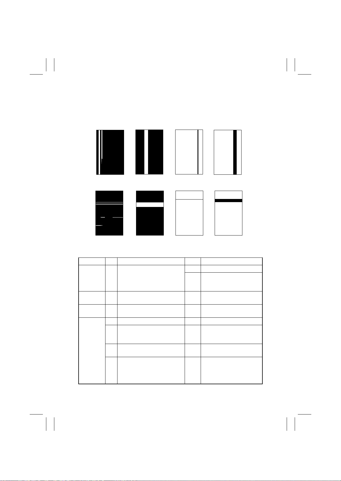
FrameMaker Ver.5.5E(PC) 8020/8031 TROUBLESHOOT ING
02.08.19
(14) Printer Monocolor: white lines in FD, white bands in FD, c olored lines in FD,
colored bands in FD, white lines in CD, white bands in CD, colored lines in CD,
colored bands in CD
<Typical Faulty Images>
White lines in FD White bands in FD Colored lines in FD Colored bands in FD
4011T015AA 4011 T020A A 4011T017AA 4011T023AA
White lines in CD White bands in CD Colored lines in CD Colored bands in CD
4011T016AA 4011T021AA 4011T018AA 4011T022AA
<Troubleshooting Procedure>
Section Step Check Item Result Action
Image
check
IU 2 The surface of the PC Drum is
LED Assy 3 The surface of the lens array is
IU 4 Dirty on the outside. YES Clean.
1 A white line or black line in FD is
sharp.
scratched.
dirty.
5 Connectors and contact termi-
nals make good connection
between each IU and LED Assy.
6 Developing bias contact termi-
nal makes good connection.
7 The problem has been elimi-
nated through the checks of
steps up to 6.
YES Perform LPH Chip Adjust.
NO Clean the Comb Electrode by
moving the Comb Electrode
Cleaning Lever.
YES Change IU.
YES Clean with cleaning jig.
NO Clean contact terminals.
Reconnect.
NO Clean contact terminal and
check terminal position.
NO Change IU.
→
Change Image Transfer
Belt Unit.
→
Change LPH Assy.
T-88
Page 91
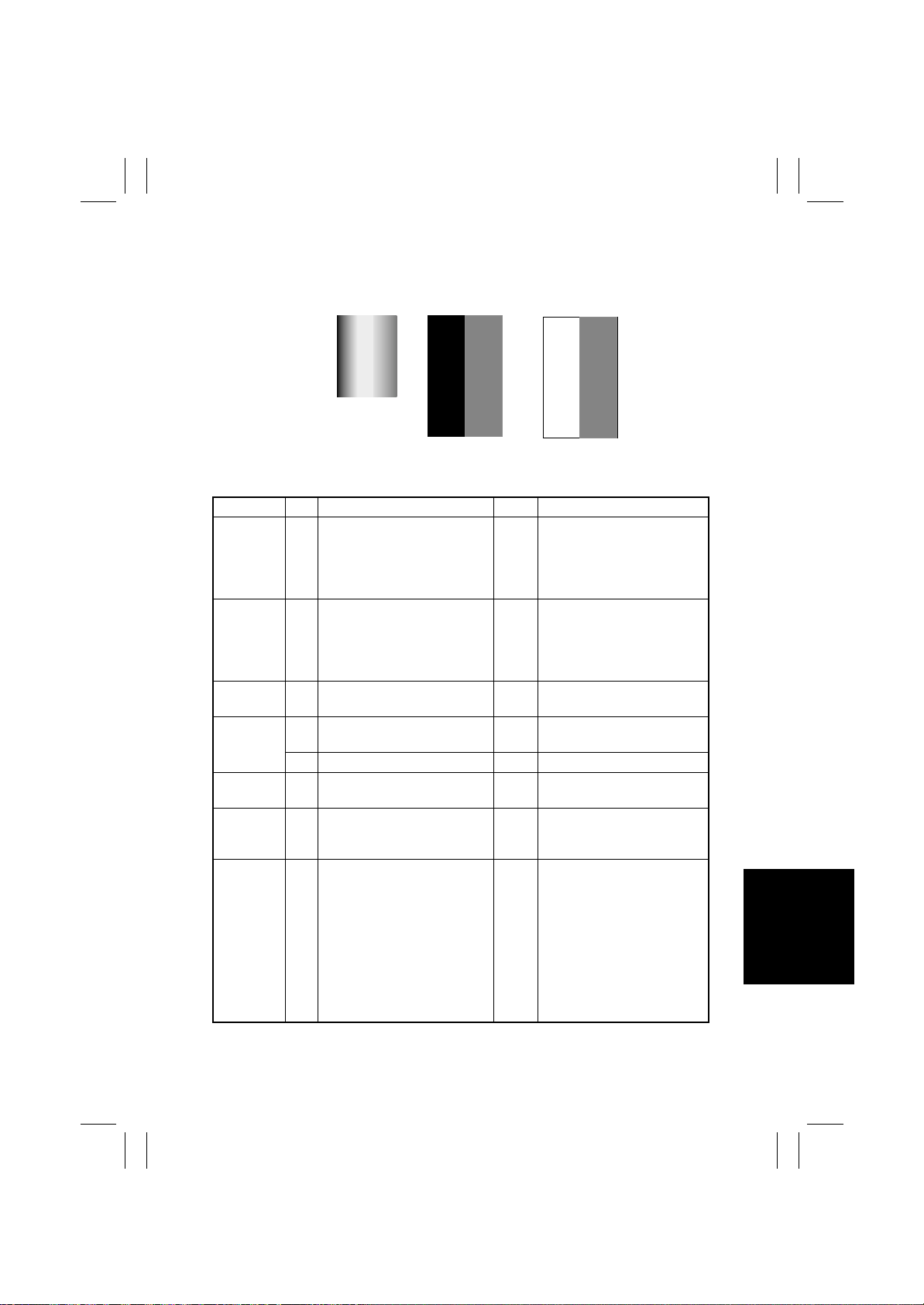
FrameMaker Ver.5.5E(PC) 8020/8031 TROUBLESHOOT ING
02.08.19
(15) Printer Monocolor: uneven density in FD
<Typical Faulty Images>
4011T031AA
4011T042AA
<Troubleshooting Procedure>
Section Step Check Item Result Action
Image
check
High image
density
original
LPH Assy 3 LED retracting lever is locked
IU 4 The surface of the PC Drum is
LPH Assy 6 LED surface is dirty . YES Clean using the LED Cleaning
Image
Transfer
Belt Unit
1 Uneven density of void area
occurs.
2 Uneven density in FD occurs
at a pitch of 40 mm to 50 mm
when a multi-copy cycle is run
using an original with high
image density (50 % or more).
in position.
scratched.
5 Dirty on the outside. YES Clean.
7 Cam gear operates properly. NO Change Image Transfer Belt
8 The problem has been elimi-
nated through the checks of
steps up to 7.
YES Check LPH Unit connector for
proper connection.
Check the LED Drive Board
connectors for proper connection.
YES Feed 10 to 20 blank sheets of
paper with no originals
placed, as the IU fails to keep
up with a high demand for
toner.
NO Slide out the IU and reinstall.
YES Change IU.
Jig.
Unit.
NO Change IU.
→
Change Image Transfer
Belt Unit.
→
Change LPH Assy .
→
Change PIC Board.
→
Change LED Drive Board
→
Change LPH Unit.
→
Change High Voltage Unit
(Image Transfer, Neutralizing).
4004T011AA
T-89
Page 92
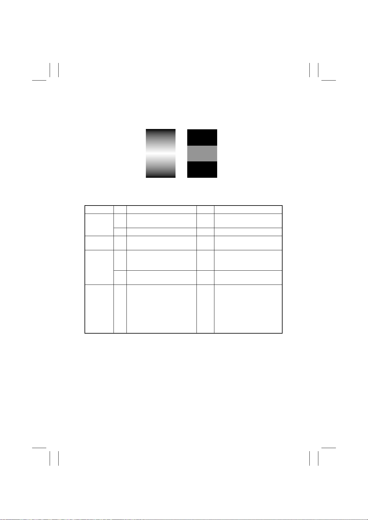
FrameMaker Ver.5.5E(PC) 8020/8031 TROUBLESHOOT ING
02.08.19
(16) Printer Monocolor: uneven density in CD
<Typical Faulty Images>
4011T032AA 4011T043AA
<Troubleshooting Procedure>
Section Step Check Item Result Action
IU 1 The surface of the PC Drum is
LPH Assy 3 The surface of the lens array is
Image
Transfer
Belt Unit
scratched.
2 Dirty on the outside. YES Clean.
dirty.
4 Image Transfer Belt Unit
makes positive contact with
plates on rails.
5 Cam gear operates properly. NO Change Image Transfer Belt
6 The problem has been elimi-
nated through the checks of
steps up to 5.
YES Change IU.
YES Clean with cleaning jig.
NO Check and correct contacts.
Unit.
NO Change IU.
→
Change Image Transfer
Belt Unit.
→
Change High Voltage Unit
(Developing Bias).
→
Change High Voltage Unit
(Image Transfer, Neutralizing).
T-90
Page 93
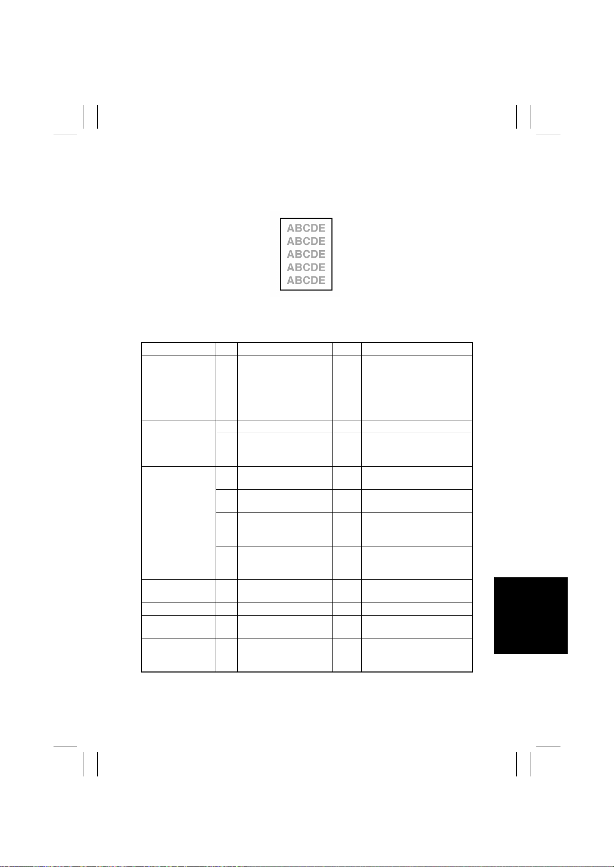
FrameMaker Ver.5.5E(PC) 8020/8031 TROUBLESHOOT ING
02.08.19
(17) Printer Monocolor: low image density
<Typical Faulty Image>
4011T003AA
<Troubleshooting Procedure>
Section St ep Check Item Result Action
1 Check data for Vg and
State Confirm
Table #
(Tech. Rep. Mode)
State Confirm
Level History 1
(Tech. Rep. Mode)
Level History data
check results
LPH Assy 8 LED retracting lever is
IU
LPH Assy 10 The surface of the lens
ATDC Sensor window
→
→
Vb.
Color Vb: Around 400 V
Vg: Around 550 V
Black Vb: Around 400 V
Vg: Around 550 V
2 Check ATDC data. — Go to next step.
3 AIDC output value is
around 4.5 V.
4 Low ATDC and low Vg
and Vb
Low ATDC and high Vg
5
and Vb
ATDC falling within spec-
6
ified range and low Vg
and Vb
ATDC falling within spec-
7
ified range and high Vg
and Vb
locked in position.
9 Dirty on the outside. YES Clean.
array is dirty.
11 The color ATDC Sensor
window on the LED Assy
is dirty.
NO Go to next step.
NO Clean AIDC Sensor.
Check Image Transfer Belt
for damage.
YES Go to step 8.
YES Go to step 14.
YES Go to step 8.
YES Go to step 14.
NO Slide out the IU and reinstall.
YES Clean with cleaning jig.
YES Clean. Change ATDC.
Change IU.
T-91
Page 94
FrameMaker Ver.5.5E(PC) 8020/8031 TROUBLESHOOT ING
02.08.19
Section St ep Check Item Result Action
Image T ransfer Belt
Unit
Hopper Unit 14 Connectors are loose. YES Reconnect.
Gradation Adjust
(Tech. Rep. Mode)
Image Adjust
→
PRT Max Density (Tech.
Rep.Mode)
Image Adjust
→
PRT Highlight
(Tech. Rep. Mode)
Image Adjust
→
Stabilizer
Reset + Stabilizer
(Tech. Rep. Mode)
→
12 Image Transfer Belt Unit
makes positive contact
with plates on rails.
13 Cam gear operates
properly.
15 Gear is cracked. YES Change gear.
16 Toner empty lev er and/or
detecting switch are
defective.
17 “Conv. Value” falls within
the specified range as
checked through Gradation Adjust.
Max: 0 ±100
Highlight = 0 ±60
18 The problem has been
eliminated through the
adjust of PRT Max.
19 The problem has been
eliminated through the
adjust of PRT Highlight.
20 After the Reset + Stabi-
lizer sequence has been
completed, run Gradation Adjust; if the problem persists, make
adjustments of PRT Max
Density and PRT Highlight.
21 The problem has been
eliminated through the
checks of steps up to 20.
NO Check and correct contacts.
NO Change Image Transfer Belt
Unit.
YES Change Hopper Unit.
NO Go to step 21.
NO Go to next step.
NO Go to next step.
NO Go to next step.
NO Change IU.
→
Change Image Transfer
Belt Unit.
→
Change LPH Assy.
→
Change PIC Board.
→
Change LED Drive Board.
→
Change LPH Unit.
→
Change High Voltage Unit
(Developing Bias).
→
Change High Voltage Unit
(Image Transfer, Neutralizing).
T-92
Page 95
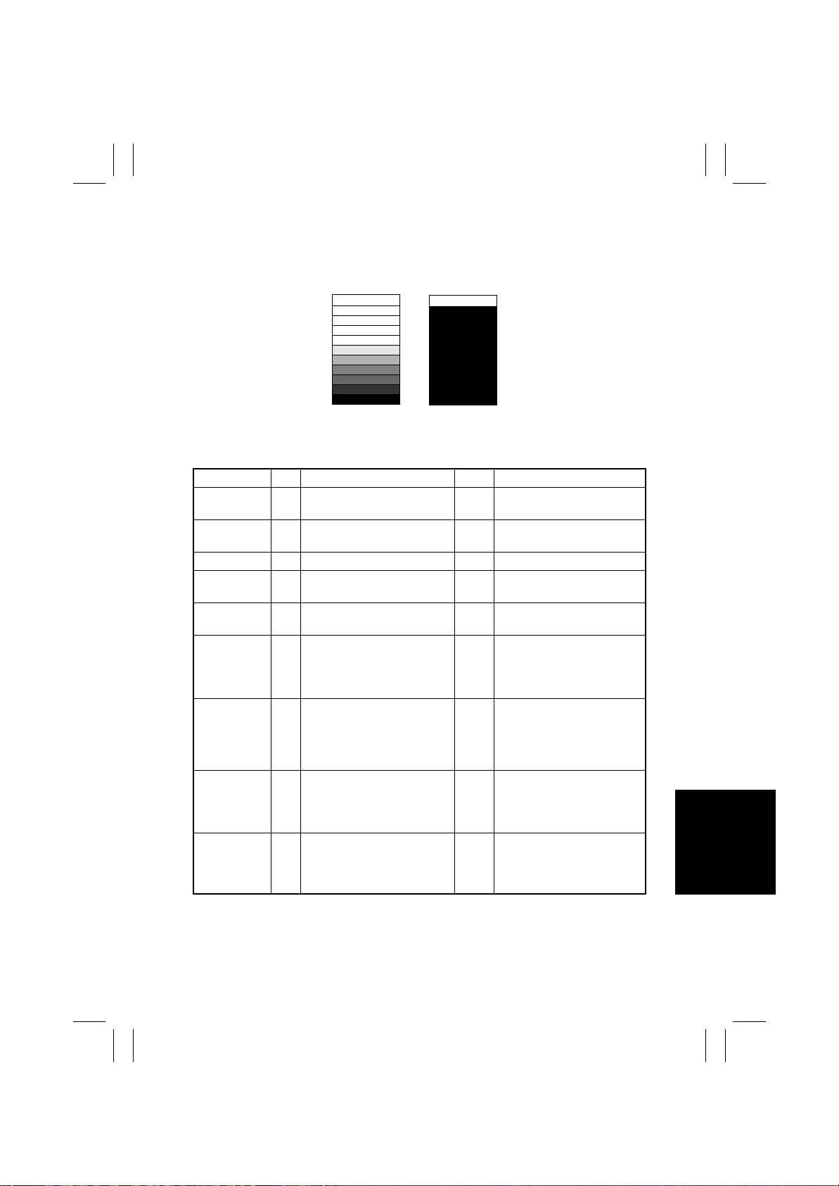
FrameMaker Ver.5.5E(PC) 8020/8031 TROUBLESHOOT ING
02.08.19
(18) Printer Monocolor: grada tion reproduction failure
<Typical Faulty Images>
4011T034AA 4011T029AA
<Troubleshooting Procedure>
Section Step Check Item Result Action
Photo/
Density
LPH Assy 2 LED retracting lever is locked
IU 3 Dirty on the outside. YES Clean.
LPH Assy 4 The surface of the lens array
ATDC Sensor
window
State Confirm
→
Level History 1 (Tech.
Rep. Mode)
Gradation
Adjust (Tech.
Rep. Mode)
Image Adjust
→
PRT Max
Density (T ech.
Rep.Mode)
Image Adjust
→
PRT Highlight (Tech.
Rep. Mode)
1 Original type and screen pat-
tern are selected properly.
in position.
is dirty.
5 ATDC Sensor window is dirty. YES Clean.
6 AIDC output value is around
4.2 V.
7 “Conv . Value” falls within the
specified range as checked
through Gradation Adjust.
Max: 0 ±100
Highlight = 0 ±60
8 The problem has been elimi-
nated through the adjust of
PRT Max.
9 The problem has been elimi-
nated through the adjust of
PRT Highlight.
NO Change screen pattern.
YES Slide out the Imaging Unit
and reinstall.
YES Clean with cleaning jig.
NO Clean AIDC Sensor.
Check Image Transfer Belt
for damage.
NO Go to step 11.
NO Go to next step.
NO Go to next step.
T-93
Page 96
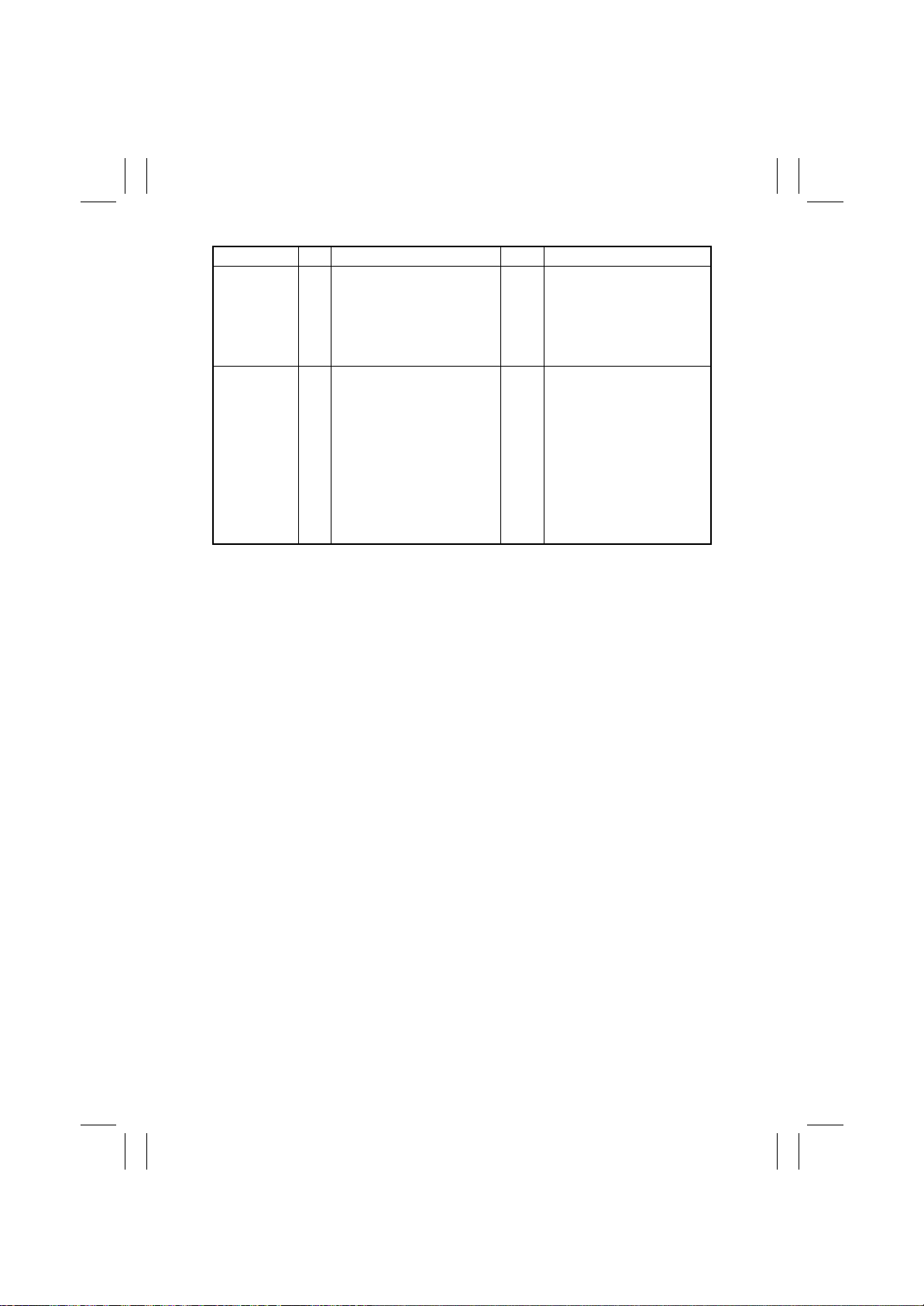
FrameMaker Ver.5.5E(PC) 8020/8031 TROUBLESHOOT ING
02.08.19
Section Step Check Item Result Action
Image Adjust
→
Stabilizer
→
Reset +
Stabilizer
(Tech. Rep.
Mode)
10 After the Reset + Stabilizer
sequence has been completed, run Gradation Adjust;
if the problem persists, make
adjustments of PRT Max
Density and PRT Highlight.
11 The problem has been elimi-
nated through the checks of
steps up to 10.
NO Go to next step.
NO Change IU.
→
Change LPH Assy.
→
Change PIC Board.
→
Change LED Drive Board.
→
Change LPH Unit.
→
Change High Voltage Unit
(Developing Bias).
→
Change High Voltage Unit
(Image Transfer, Neutralizing).
T-94
Page 97
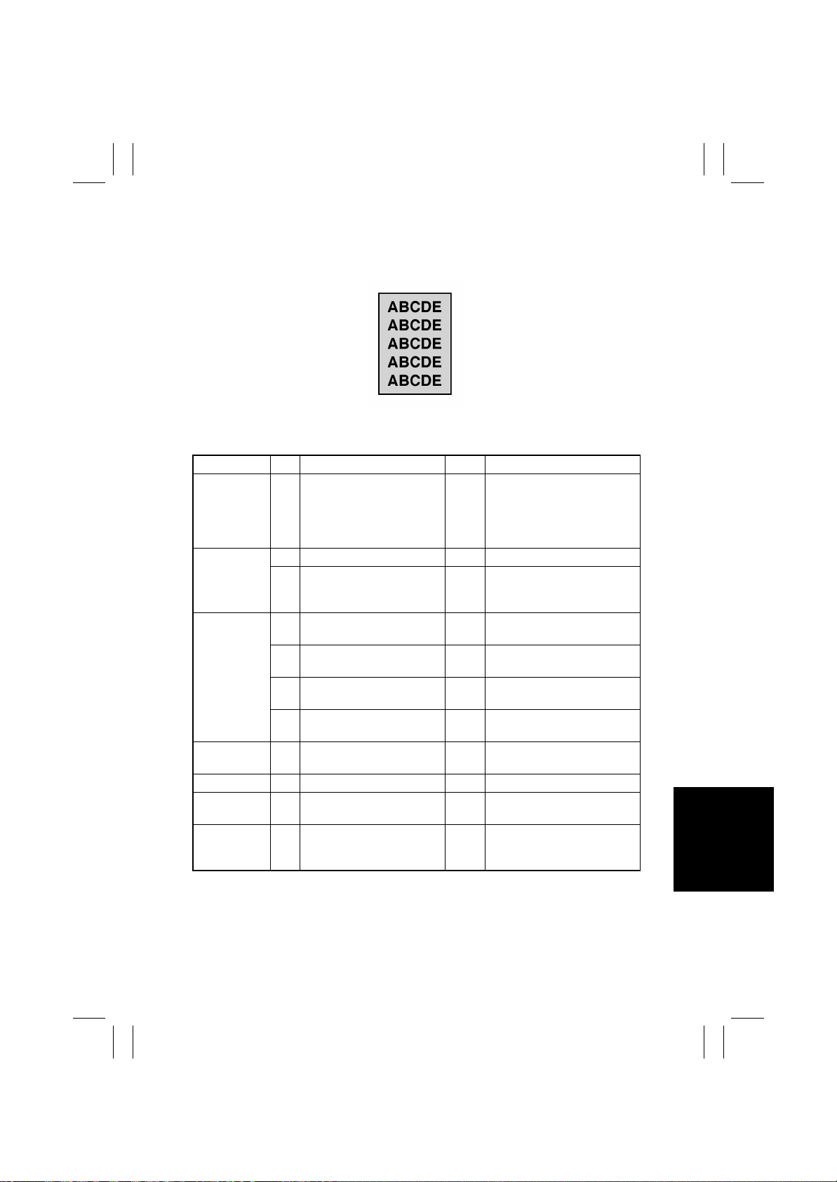
FrameMaker Ver.5.5E(PC) 8020/8031 TROUBLESHOOT ING
02.08.19
(19) Printer Monocolor: foggy background
<Typical Faulty Image>
4011T004AA
<Troubleshooting Procedure>
Section Step Check Item Result Ac tion
State Confirm
→
Table #
(Tech. Rep.
Mode)
State Confirm
→
Level History 1 (Tech.
Rep. Mode)
Level History
data check
results
1 Check data for Vg and Vb.
Color Vb: Around 400 V
Vg: Around 550 V
Black Vb: Around 400 V
Vg: Around 550 V
2 Check ATDC data. — Go to next step.
3 AIDC output value is around
4.5 V.
4 Low ATDC and low Vg and VbYES Go to step 8.
Low ATDC and high Vg and VbYES Go to step 12.
5
NO Go to next step.
NO Clean AIDC Sensor.
Check Transfer Belt for damage.
A TDC f alling within specified
6
range and low Vg and Vb
A TDC f alling within specified
7
range and high Vg and Vb
LPH Assy 8 LED retracting lever is
IU
LPH Assy 10 The surface of the lens
ATDC Sensor
window
locked in position.
9 Dirty on the outside. YES Clean.
array is dirty .
11 The color ATDC Sensor
window on the LED Assy is
dirty.
T-95
YES Go to step 8.
YES Go to step 12.
NO Slide out the IU and reinstall.
YES Clean with cleaning jig.
YES Clean. Change ATDC.
Change IU.
Page 98
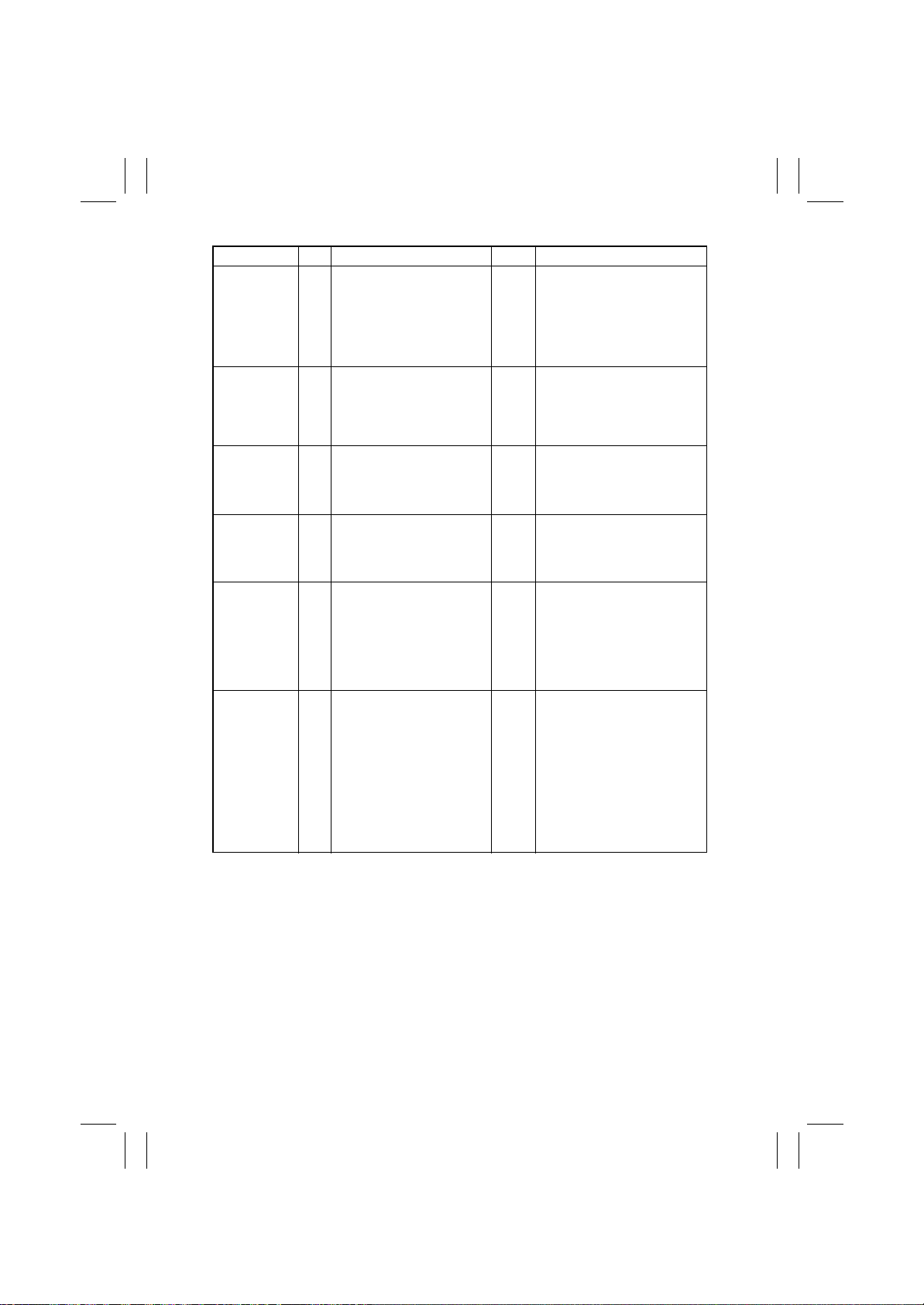
FrameMaker Ver.5.5E(PC) 8020/8031 TROUBLESHOOT ING
02.08.19
Section Step Check Item Result Ac tion
Image
→
Adjust
ground V oltage Margin
(Tech. Rep.
Mode)
Gradation
Adjust (Tech.
Rep. Mode)
Image Adjust
→
PRT Max
Density (T ech.
Rep.Mode)
Image Adjust
→
PRT Highlight (Tech.
Rep. Mode)
Image Adjust
→
Stabilizer
→
Reset +
Stabilizer
(Tech. Rep.
Mode)
12 The problem is eliminated
Back
after Background Voltage
Margin has been adjusted.
13 “Conv. V alue” fal ls within the
specified range as checked
through Gradation Adjust.
Max: 0 ±100
Highlight = 0 ±60
14 The problem has been elim-
inated through the adjust of
PRT Max.
15 The problem has been elim-
inated through the adjust of
PRT Highlight.
16 After the Reset + Stabilizer
sequence has been completed, run Gradation
Adjust; if the problem persists, make adjustments of
PRT Max Density and PRT
Highlight.
17 The problem has been elim-
inated through the checks of
steps up to 16.
NO Go to next step.
NO Go to step 17.
NO Go to next step.
NO Go to next step.
NO Go to next step.
NO Change IU.
→
Change LPH Assy .
→
Change PIC Board.
→
Change LED Drive Board.
→
Change LPH Unit.
→
Change High Voltage Unit
(Developing Bias).
→
Change High Voltage Unit
(Image Transfer, Neutralizing).
T-96
Page 99
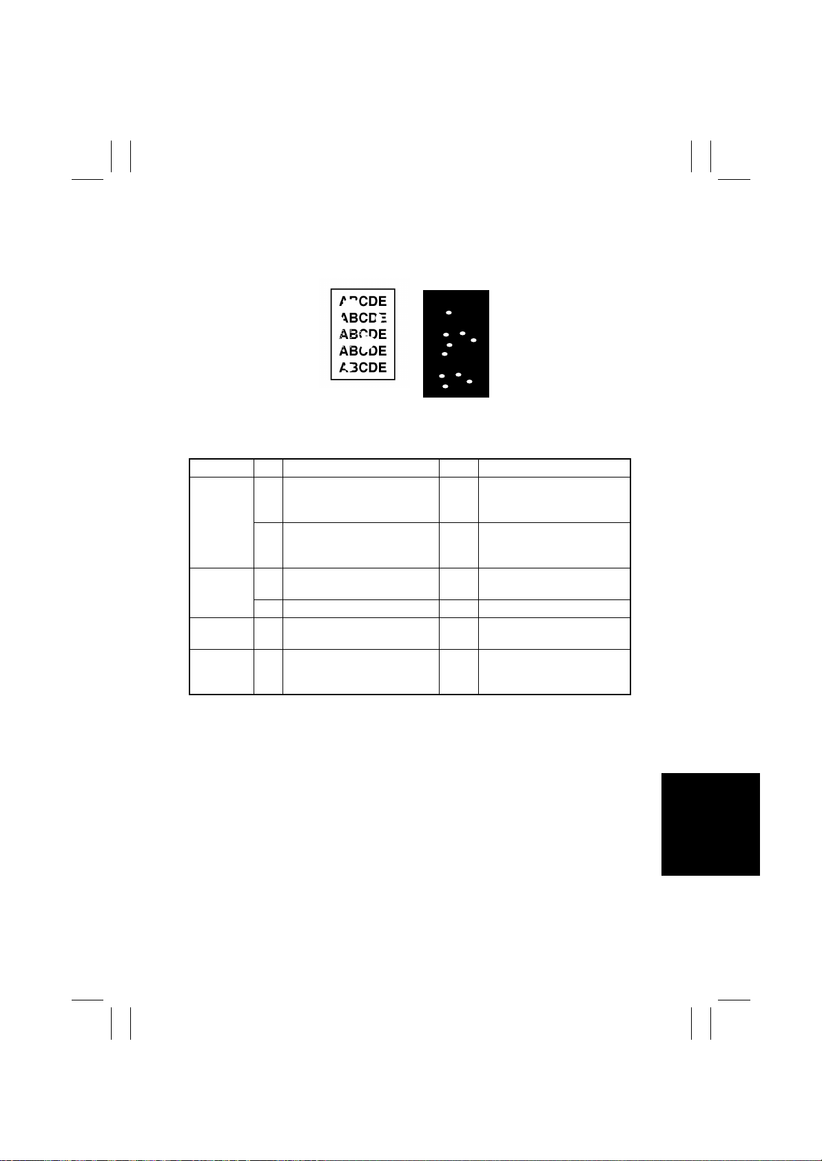
FrameMaker Ver.5.5E(PC) 8020/8031 TROUBLESHOOT ING
02.08.19
(20) Printer Monocolor: void areas, white spots
<Typical Faulty Images>
Void areas White spots
4011T008AA
4011T030AA
<Troubleshooting Procedure>
Section Step Check Item Result Action
Image
Check
1 There are void areas at the
front side or high density sec-
YES☞ T-9 1
tion.
2 There is void area at the rear
side section.
YES Perform “2nd Transfer Adjust”
of “Image Adjust” under Tech.
Rep. mode.
IU 3 The surface of the PC Drum is
YES Change Imaging Unit.
scratched.
4 Dirty on the outside. YES Clean.
Hopper Unit 5 Foreign matter or caked toner
YES Remove foreign matter.
in the Toner Cartridge.
6 The problem has been elimi-
NO Change IU.
nated through the checks of
steps up to 5.
T-97
Page 100
FrameMaker Ver.5.5E(PC) 8020/8031 TROUBLESHOOT ING
02.08.19
(21) Printer Monocolor: colored spots
<Typical Faulty Image>
C F
4011T027AA
<Troubleshooting Procedure>
Section Step Check Item Result Action
IU 1 Developing bias contact termi-
nal makes good connection.
2 The surface of the PC Drum is
scratched.
3 Dirty on the outside. YES Clean.
4 The problem has been elimi-
nated through the checks of
steps up to 3.
NO Clean contact terminal and
check terminal position.
YES Change Imaging Unit.
NO Change IU.
T-98
 Loading...