

Page 1

FrameMaker Ver.5.5E(PC) 8020/8031 DIS/REASSEMBLY, ADJUSTMENT
02.08.19
DIS/REASSEMBLY,
ADJUSTMENT
Page 2

FrameMaker Ver.5.5E(PC) 8020/8031 DIS/REASSEMBLY, ADJUSTMENT
02.08.19
Blank page
Page 3
FrameMaker Ver.5.5E(PC) 8020/8031 DIS/REASSEMBLY, ADJUSTMENT
02.08.19
1. SERVICE INSTRUCTIONS
1-1. IDENTIFICATION OF FUSES
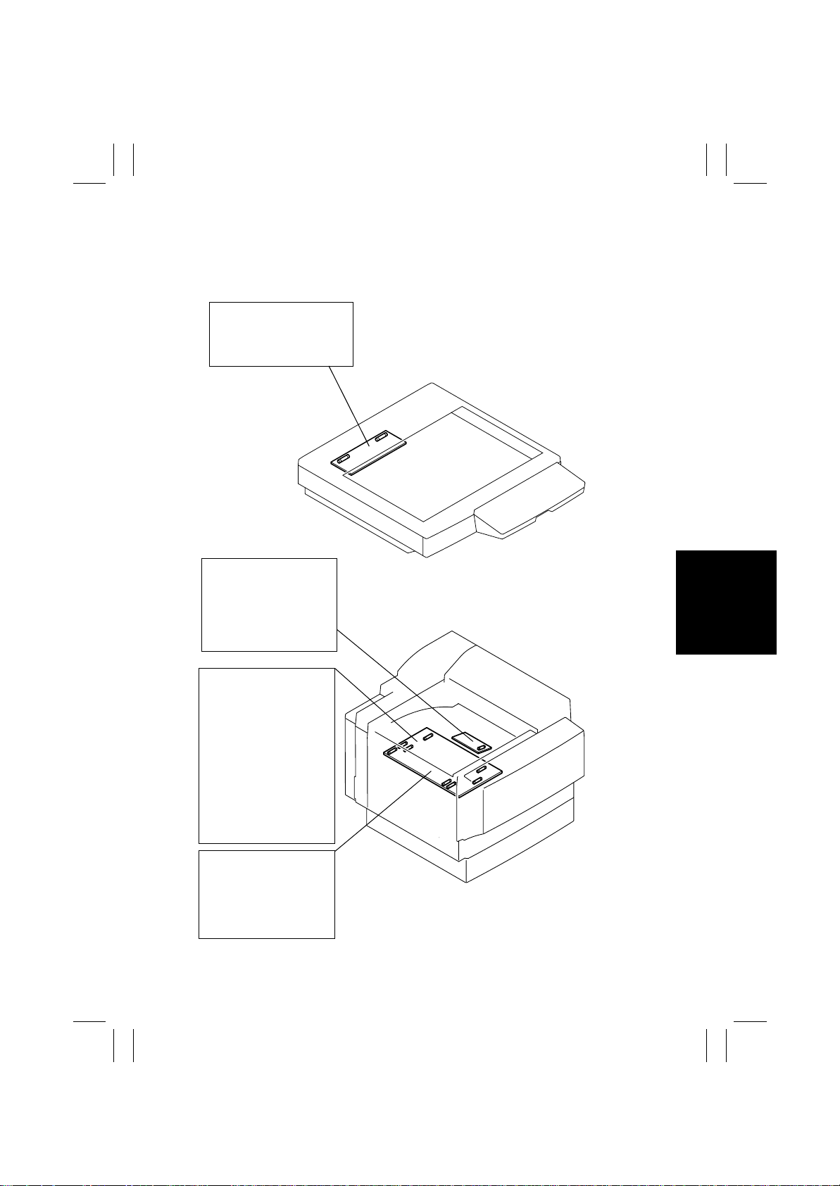
DC Power Supply 3 PU201
F1: 250 V 5 A
F100: 250 V 3.15 A
DC Power Supply 2 PU2
100 V Area
F1: 125 V 4 A
200 V Area
F1: 250 V 4 A
DC Power Supply 1 PU1
100 V Area
F1: 250 V 15 A
F2: 250 V 15 A
F3: 250 V 15 A
F4: 250 V 15 A
200 V Area
F1: 250 V 8 A
F2: 250 V 8 A
F3: 250 V 8 A
F4: 250 V 8 A
DC Power Supply 1 PU1
F101: 250 V 3.15 A
F102: 250 V 3.15 A
F103: 250 V 3.15 A
F104: 250 V 3.15 A
4025D001AA
4025D002AB
D-1
Page 4

FrameMaker Ver.5.5E(PC) 8020/8031 DIS/REASSEMBLY, ADJUSTMENT
02.08.19
1-2. PARTS WHICH MUST NOT BE TOUCHED
(1) Red painted Screws
Purpose of Application of Red Paint
Red painted screws show that the assembly or unit secured can only be adjusted or set at
the factory and should not be adjusted, set, or removed in the field.
Note that when two or more screws are used on the part in questions, only one representative screw may be marked with red paint.
(2) Variable Resistors on Board
Do not turn the variable resistors on boards for which no adjusting instructions are given in
“ADJUSTMENT.”
D-2
Page 5
FrameMaker Ver.5.5E(PC) 8020/8031 DIS/REASSEMBLY, ADJUSTMENT
02.08.19
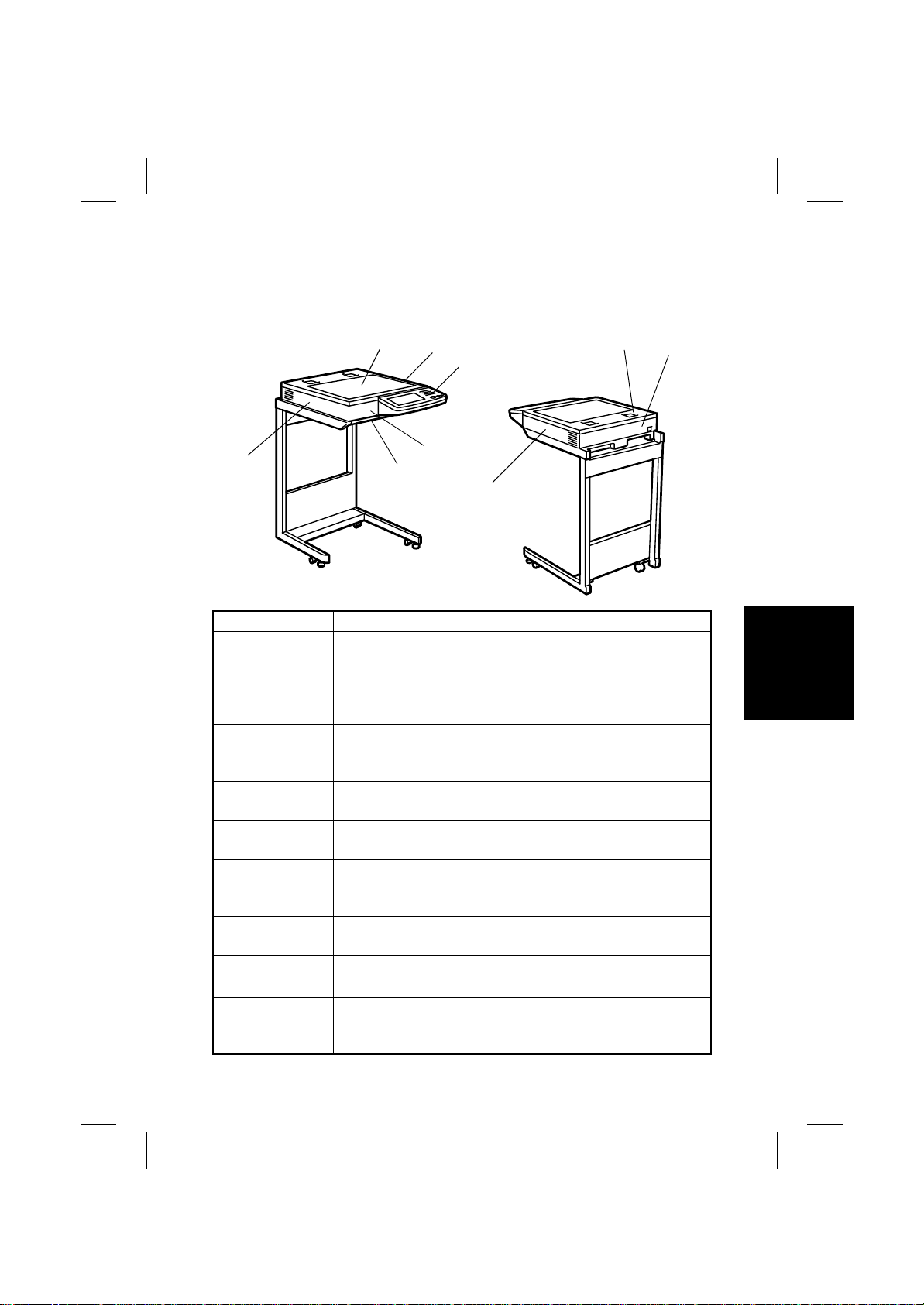
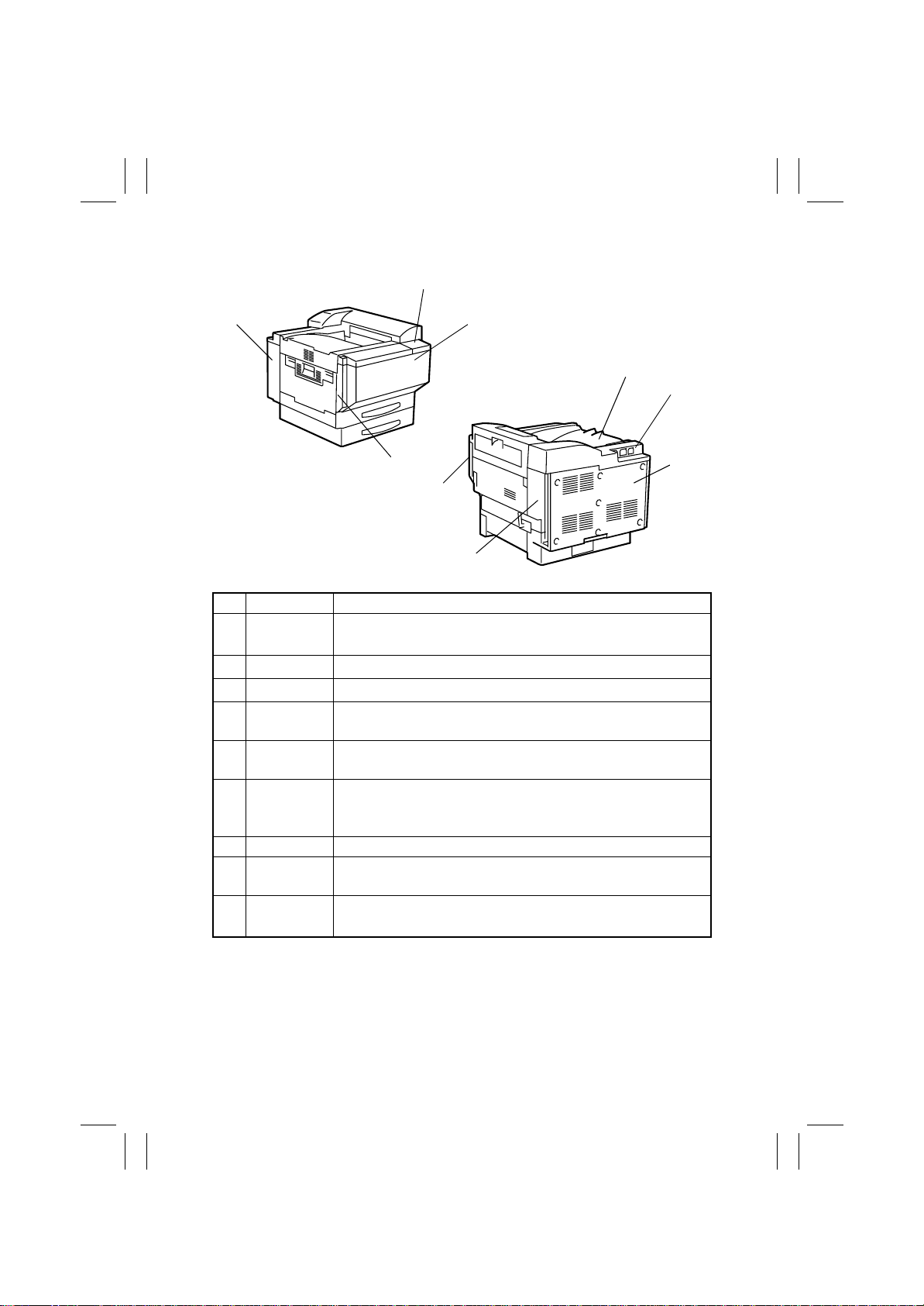
2. DISASSEMBLY/REASSEMBLY
2-1. DOORS, COVERS, AND EXTERIOR PARTS:
IDENTIFICATION AND REMOVAL PROCEDURES
1
6
4025D003AA
No. Name Removal Procedure
Remove the IR Upper Right Cover.
1 Original Glass
IR Upper Right
2
Cover
3 Control Panel
4 IR F ront Cov er
IR Lower Front
5
Cover
6 IR Left Cover
IR Upper
7
Cover
8 IR Rear Cover
9 IR Right Cover
Original Glass fixing brackets (front and rear).
nal Glass.
Remove three screws and the IR Upper Right Cover.
Remove the four caps on both sides of the control panel.
Remove four screws and the flat cable.
panel.
Remove the IR Lower Front Cover.
remove the IR Front Cover.
Remove the pipe ends (left and right).
the IR Lower Front Cover.
Remove the IR Upper Cover.
Demount the IR Unit from the Copier Stand.
and the IR Left Cover.
Remove the Original Cover.
Upper Cover.
Disconnect the power cable and ADF cable.
Upper Cover.
Remove the IR Upper Cover.
Demount the IR Unit from the Copier Stand.
and the IR Right Cover.
2
3
4
5
9
→
Remove one screw and the
→
→
Loosen three screws and
→
Remove two screws and
→
Remove the IR Rear Cover. →
→
Remove six screws and the IR
→
Remove two screws and the IR Rear Cover.
→
Remove the IR Rear Cover. →
7
8
4025D004AA
→
Remove the Origi-
→
Remove the control
→
Remove four scre ws
→
Remove the IR
→
Remove four scre ws
D-3
Page 6
FrameMaker Ver.5.5E(PC) 8020/8031 DIS/REASSEMBLY, ADJUSTMENT
02.08.19
2
1
4025D005AA
4
No. Name Removal Procedure
Rear Left
1
Cover
2 Panel Cover
3 Front Door
Hopper Left
4
Cover
Paper Output
5
Cover
Rear Upper
6
Cover
7 Rear Cover Remove seven screws and the Rear Cover.
Rear Right
8
Cover
Front Right
9
Cover
Open the Left Door.
the Ozone Filter.
Open the Front Door.
Open the Front Door.
Open the Front Door.
Cover upward to take it off.
Open the Upper Right Door.
Output Cover.
Remove the Paper Output Cover.
Remove the deodorant filter.
Upper Cover.
Open the Right Door.
Remove one screw and the Rear Right Cover.
Open the Right Door.
the Panel Cover.
3
9
8
→
Remove the W aste Toner Bottle. → Remov e
→
Remove two screws and the Rear Left Cover.
→
Remove one screw and the Panel Cover.
→
Lift the Front Door off the copier.
→
Remove one screw and lift the Hopper Left
→
Remove two screws and the Paper
→
Remove the Rear Cover. →
→
Remove three screws and the Rear
→
Remove the Rear Upper Cover. →
→
Open the Upper Right Door. → Remove
→
Remove one screw and the Front Right Cover.
5
6
7
4025D006AA
D-4
Page 7
FrameMaker Ver.5.5E(PC) 8020/8031 DIS/REASSEMBLY, ADJUSTMENT
02.08.19
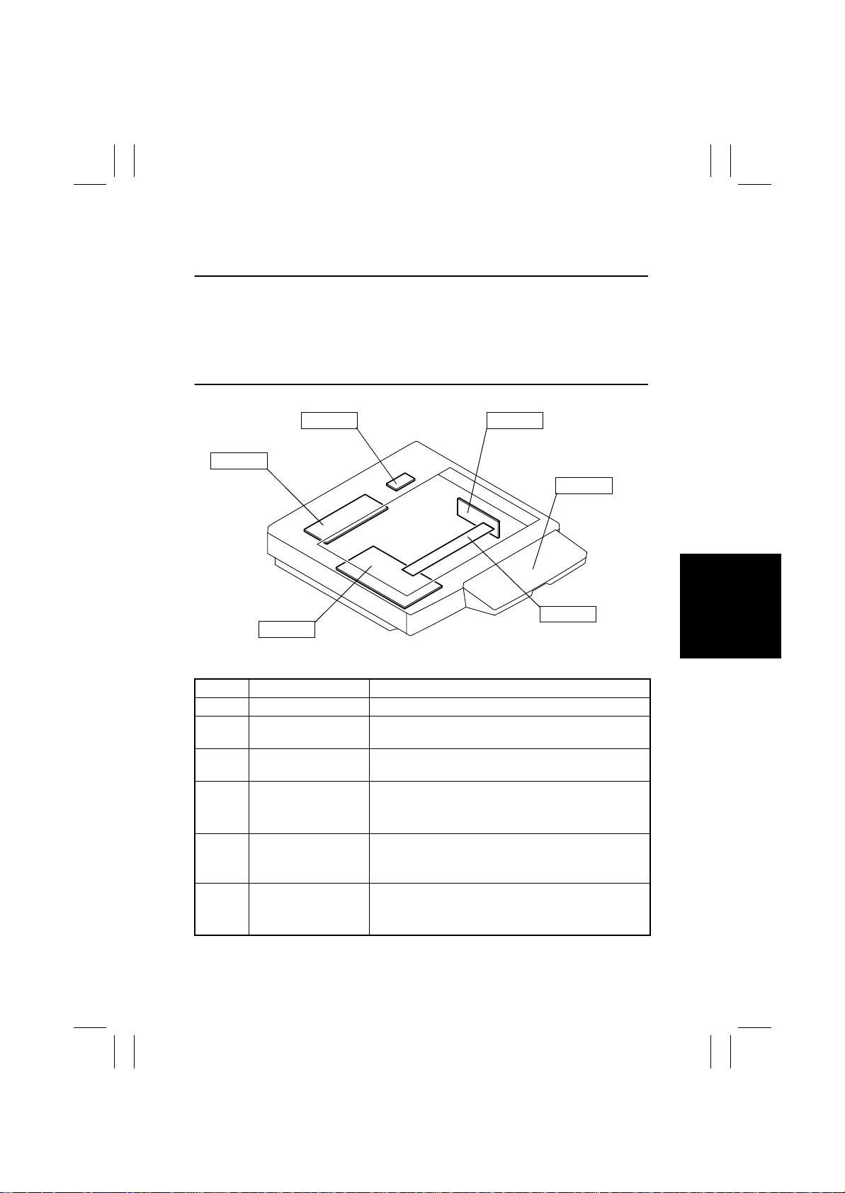
2-2. REMOVAL OF CIRCUIT BOARDS AND OTHER ELECTRICAL
COMPONENTS
NOTES
• When removing a circuit board or other electrical component, refer to “Handling of
PWBs” and follow the corresponding removal procedures.
• The removal procedures given in the following omit the removal of connectors and
screws securing the circuit board support or circuit board.
• Where it is absolutely necessary to touch the ICs and other electrical components on the
board, be sure to ground your body.
PWB-IC
PU201
PWB-C
Symbol Name Removal Procedure
- CCD Unit
PWB-B
PWB-C
PWB-IC
UN201 Control Panel
PU201 DC Power Supply 3
Image Processing
Interface Board
Image Processing
Board
Scanner Motor Drive
Board
☞
D-8
☞
D-10
☞
D-10
✽
Upgrade the firmware after the replacement.
Remove the IR Rear Cover .
the reinforcement frame.
Motor Drive Board.
Remove the four rubber caps on the right and left and
remove four screws.
then remove the flat cable from the control panel.
Remove the IR Rear Cover.
the reinforcement frame.
DC Power Supply 3.
CCD Unit
4025D007AA
→
Remove 11 screws and
→
Remove the Scanner
→
Remove the control panel and
→
Remove 11 screws and
→
Remove five screws and
UN201
PWB-B
D-5
Page 8
FrameMaker Ver.5.5E(PC) 8020/8031 DIS/REASSEMBLY, ADJUSTMENT
02.08.19
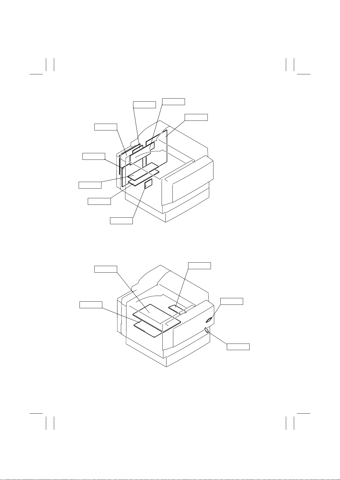
PWB-IO
PWB-PIC
HV1
HV3
PU1
PWB-I
PWB-G
HV2
PWB-F
4025D008AA
PU2
PWB-LED
PWB-S1
PWB-S
4025D009AB
D-6
Page 9
FrameMaker Ver.5.5E(PC) 8020/8031 DIS/REASSEMBLY, ADJUSTMENT
02.08.19
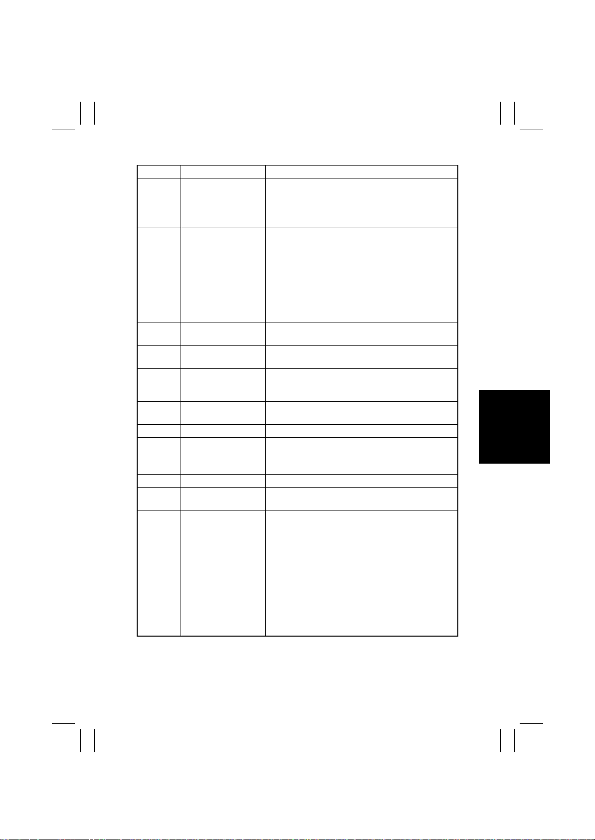
Symbol Name Removal Procedure
Remove the Rear Upper Cover.
→
PWB-IO IO Board
PWB-G Option Interface Board
PWB-PIC PIC Board
PWB-F Image Control Board
HV1
Have
Have
Put DC Power Supply 1
Put DC Power Supply 2
PWB-LED LED Drive Board
PWB-I
PWB-So
PWB-So
High Voltage Unit
(PC DRUM CH.)
High Voltage Unit
(Image Transfer, Neutralizing)
High Voltage Unit
(Developing Bias)
Paper Size Detecting
Board
Paper Type Dete ction
Board
Tech. Rep. Setting
Switches Board
Left Cover.
rear left me tal bracket.
the IO Board.
Remove the Main Board.
slide the Option Interface Board off the copier.
Remove the Main Board.
the harness protective metal bracket.
nine screws and the rear left metal bracket.
Remove PWB-F.
PIC Board.
✽
Upgrade the firmware after the replacement.
☞
D-12
✽
Upgrade the firmware after the replacement.
☞
D-13
☞
D-13
☞
D-13
☞
D-15
Remove the Paper Output Cover and Rear Upper
Cover.
→
Remove three screws and DC Power Supply 2.
☞
D-41
☞
D-13
Open the Front Door.
→
Remove one screw and the Paper Type Detection
Board cover .
Type Detection Board.
✽
There are locking tabs inside the Paper Type
Detection Board cover . Try to expand both sides of
the cover when removing it.
Open the Front Door.
→
Remove two screws and the Right Front Cov er . →
Remove one screw and the Tech. Rep. Setting
Switches Board.
Remove three screws and the upper
→
Remove five screws and
→
Remove four screws and
→
Remove fiv e scre ws and
→
Remove eight screws and the
→
Remove four screws and the PWB cover.
→
Slide out the paper drawer.
→
Remove one screw and the Paper
→
Remove the Panel Cover.
→
Remove the Rear
→
Remove
→
D-7
Page 10
FrameMaker Ver.5.5E(PC) 8020/8031 DIS/REASSEMBLY, ADJUSTMENT
02.08.19
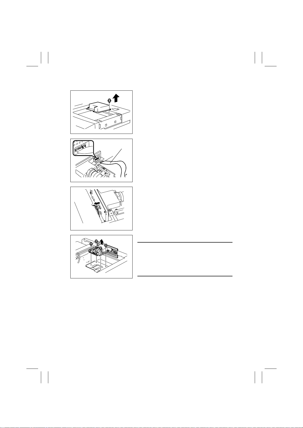
(1) Removal of the CCD Unit
1. Remove the Original Glass.
2. Remove 14 screws and optical cover.
4025E006AB
Image Processing
Interface Board
4025D113AA
4025D114AA
4025D115AA
3. Remove the Image Processing Interface Board
from the CCD Unit.
4. Unplug connector
5. Remove four screws and the CCD Unit.
NOTE
• Make doubly sure that you remove the correct
screws. If any screw that should not be removed is
removed, it results in the distance between the
lens and the CCD sensor or tilt in these parts being
varied.
D-8
Page 11
FrameMaker Ver.5.5E(PC) 8020/8031 DIS/REASSEMBLY, ADJUSTMENT
02.08.19
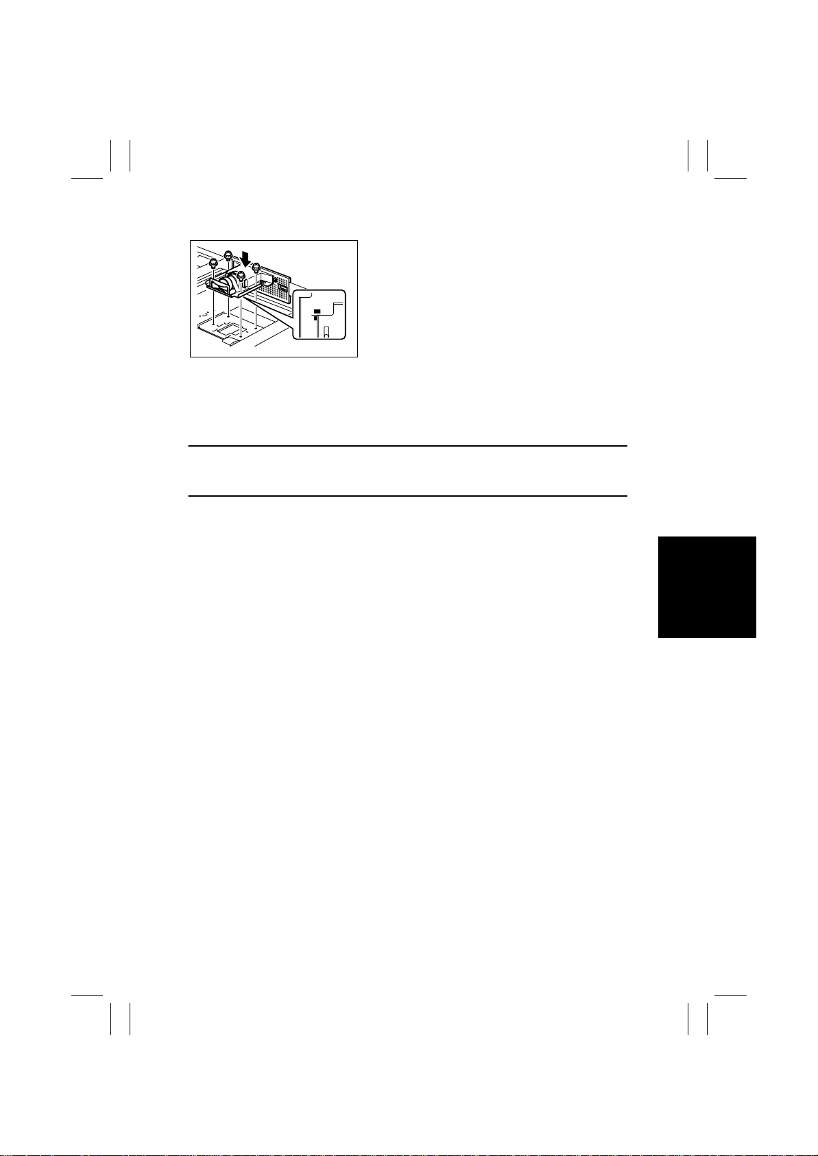
Reinstallation Procedure
1. Align the CCD Unit with the center of the graduations as illustrated on the left and then tighten the
four screws.
4025D116AA
2. Reinstall the Original Glass.
3. Turn ON the Power Switch.
4. Carry out the adjustment procedure for CD-Mag. (see D-67). If the specifications are
not met, loosen the CCD Unit mounting screws and move the CCD Unit in the FD direction as necessary.
NOTE
• Hold the CCD Unit by hand when moving it. NEVER use a screwdriver or similar tool to
tap to move it, as a varied distance between the CCD sensor and lens results.
<Adjustment Procedure>
• If the specified width on the copy is less than the specifications, move the CCD Unit to
the left.
• If the specified width on the copy is longer than the specifications, move the CCD Unit to
the right.
✽
Moving the CCD Unit over 1 mm results in the zoom ratio being varied about 2%.
5. Reversing the order of removal, reinstall all parts that have been removed.
D-9
Page 12
FrameMaker Ver.5.5E(PC) 8020/8031 DIS/REASSEMBLY, ADJUSTMENT
02.08.19
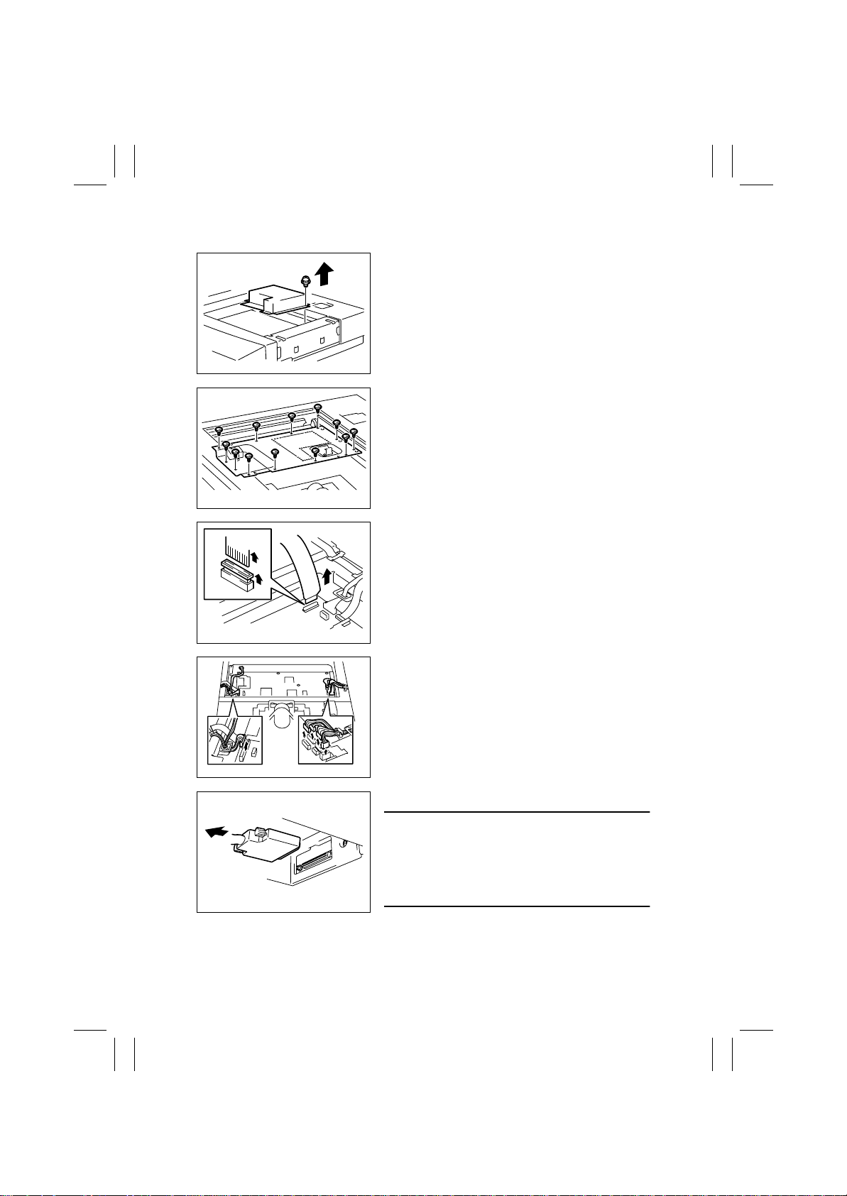
(2) Removal of the Image Processing Board and Image Processing Interface Board
1. Remove the Original Glass.
2. Remove 14 screws and optical cover.
4025E006AB
3. Unplug the connectors and remove the cord
clamps of the Original Size Detecting Sensors.
4. Remove 12 screws and the Image Processing
Board lid.
4025D010AC
5. Remove the Image Processing Interface Board.
4025D011AB
4025D012AA
4004D010AA
6. Unplug all connectors of the Image Processing
Board.
7. Remove the IR hookup cable.
NOTES
• Be sure to hold onto the connector of the cable
when removing or reinstalling the cable. NEVER
pull on the cable.
• At reinstallation, make sure that the connector is
not tilt.
D-10
Page 13
FrameMaker Ver.5.5E(PC) 8020/8031 DIS/REASSEMBLY, ADJUSTMENT
02.08.19
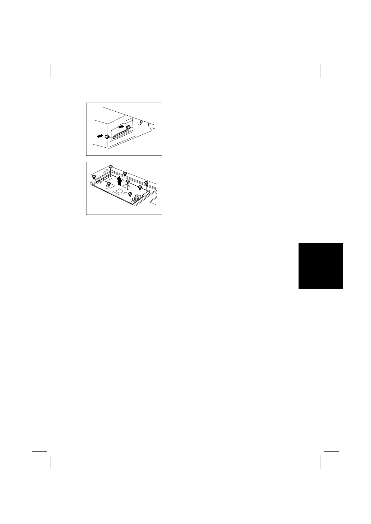
8. Remove two screws.
4025D013AA
9. Remove eight screws and the Image processing
Board.
✽
Upgrade the firmware after the replacement.
4025D014AA
D-11
Page 14
FrameMaker Ver.5.5E(PC) 8020/8031 DIS/REASSEMBLY, ADJUSTMENT
02.08.19
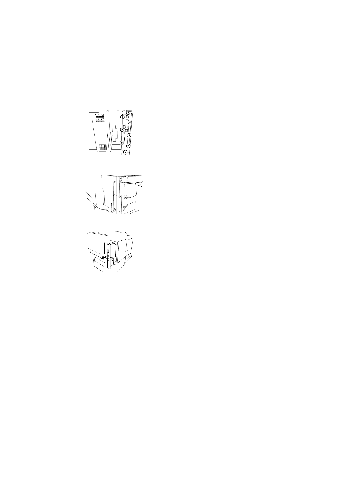
(3) Removal of the Image Control Board
<Copier Side Face>
<Copier Rear Face>
4334O014AA
4334O015AA
1. Remove the Rear Cover.
2. Remove eight screws at the I/F cable connection
(five on the side face and three on the rear f ace of
the copier).
3. Slide the Image Control Board to the left off the
copier.
✽
Remount IC202 and upgrade the firmware after
the replacement.
4334O016AA
D-12
Page 15
FrameMaker Ver.5.5E(PC) 8020/8031 DIS/REASSEMBLY, ADJUSTMENT
02.08.19
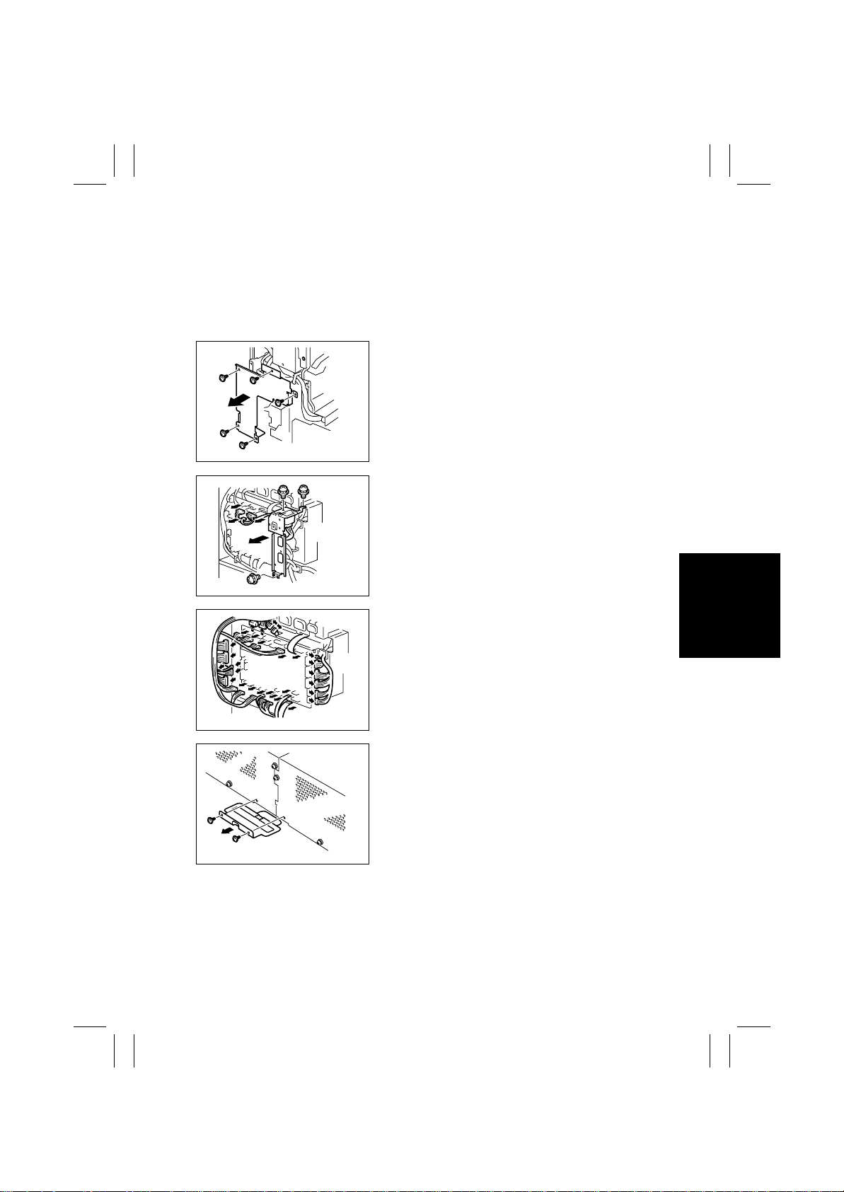
(4) Removal of the High Voltage Unit (PC Drum CH.), High Voltage Unit (Image
Transfer, Neutralizing), High Voltage Unit (Developing Bias), and Paper Size
Detecting Board
1. Remove the Rear Upper Cover.
2. Remove the Rear Left Cover.
3. Remove the Rear Right Cover.
4. Remove five screws and the harness protective
metal bracket.
4025D015AA
5. Remove three screws and unplug three connectors. Then, remove the rear left metal bracket.
4025D017AA
4025D016AA
4025D018AA
6. Unplug all connectors from the Main Board.
7. Unplug the two connectors from the Option Interface Board.
8. Unplug the two connectors from the PIC Board.
9. Remove two screws and the 2nd Drawer power
line mounting bracket.
D-13
Page 16
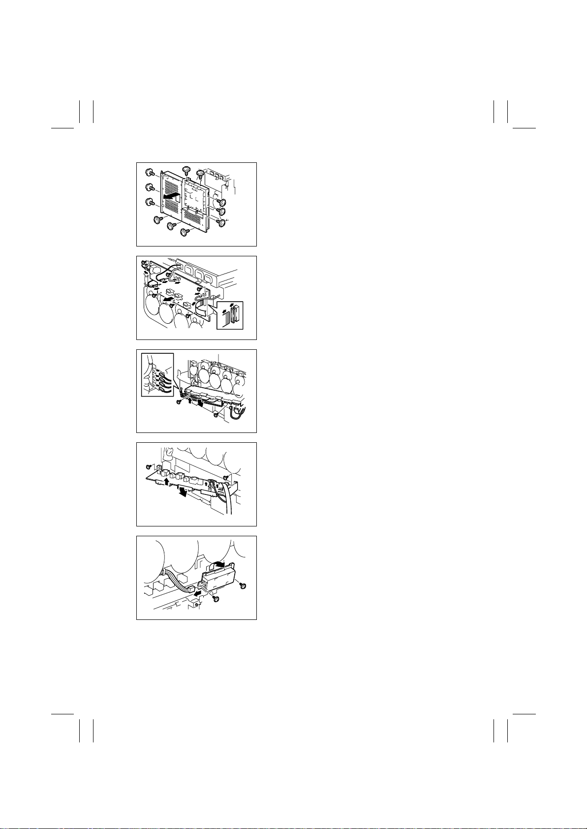
FrameMaker Ver.5.5E(PC) 8020/8031 DIS/REASSEMBLY, ADJUSTMENT
02.08.19
10. Remove 11 screws and lift the PWB box upward
and off the copier.
4025D019AA
11. Disconnect connectors, terminals, and flat cable
from the High Voltage Unit (Image Transfer, Neutralizing).
12. Remove six screws and the High Voltage Unit
(Image Transfer, Neutralizing).
4025D020AA
13. Disconnect connectors, terminals, and flat cable
from the High Voltage Unit (PC Drum CH.).
14. Remove two screws. Then, lift the High Voltage
Unit (PC Drum CH.) and take it out to the front.
4025D021AA
4025D022AA
4025D023AA
15. Disconnect the connectors and flat cable from the
High Voltage Unit (Developing Bias).
16. Remove two screws. Then, lift the High Voltage
Unit (Developing Bias) and take it out to the front.
17. Slide out the paper drawer.
18. Remove two screws, unplug the connector, and
remove the Paper Size Detecting Board.
D-14
Page 17
FrameMaker Ver.5.5E(PC) 8020/8031 DIS/REASSEMBLY, ADJUSTMENT
02.08.19
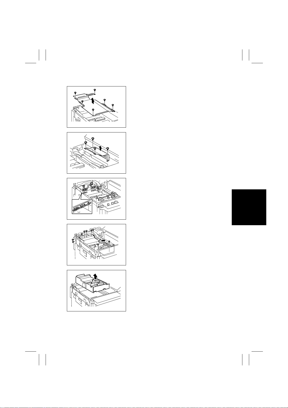
(5) Removal of DC Power Su pply 1
1. Remove the Rear Upper Cover.
2. Remove six screws and the PWB cover.
4025D024AA
3. Remove four screws and the PWB cover.
4025D025AA
4. Unplug all connectors from DC Power Supply 1.
4025D026AA
4025D027AC
4025D028AA
5. Remove nine screws and slide DC Power Supply
1 to the right.
6. Remove DC Power Supply 1.
D-15
Page 18
FrameMaker Ver.5.5E(PC) 8020/8031 DIS/REASSEMBLY, ADJUSTMENT
02.08.19
2-3. Removal of Units
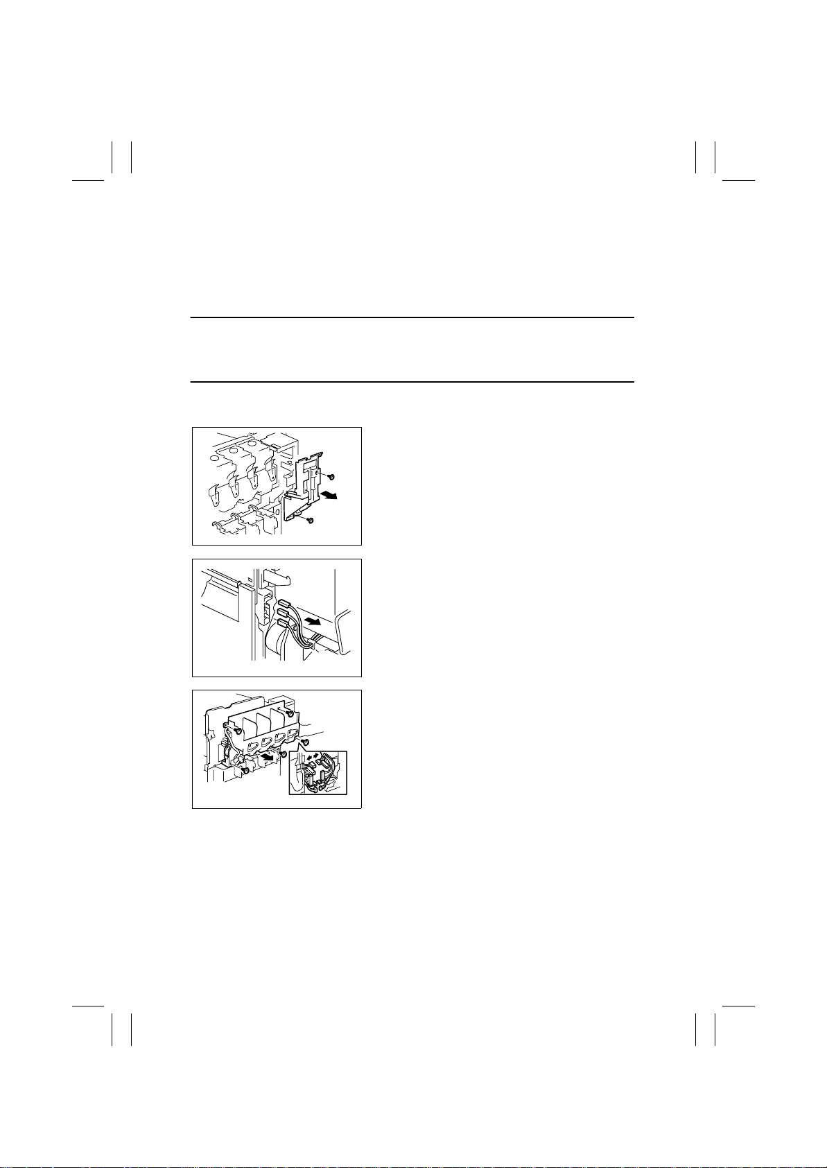
(1) Removal of the Toner Hopper Unit
1. Open the Front Door.
2. Remove the T oner Cartridge (C, M, Y, Bk).
3. Remove the IU (C, M, Y , Bk).
NOTE
• After the IU has been slid out, be sure to place it in the aluminum pack for packing or
wrap it in the light shielding cloth and store it in a dark place. Do not leav e the IU to stand
for a l ong time.
4. Remove the hopper left cover.
5. Remove the Front Right Cover.
6. Remove two screws and the Front Door Switch
cover.
4025D029AA
4004D045AA
4025D030AA
7. Disconnect terminals.
✽
Terminals (from top downward): blue, white, and
green
8. Disconnect five connectors.
9. Remove five screws and the Toner Hopper Unit.
D-16
Page 19
FrameMaker Ver.5.5E(PC) 8020/8031 DIS/REASSEMBLY, ADJUSTMENT
02.08.19
(2) Removal of the LPH Unit
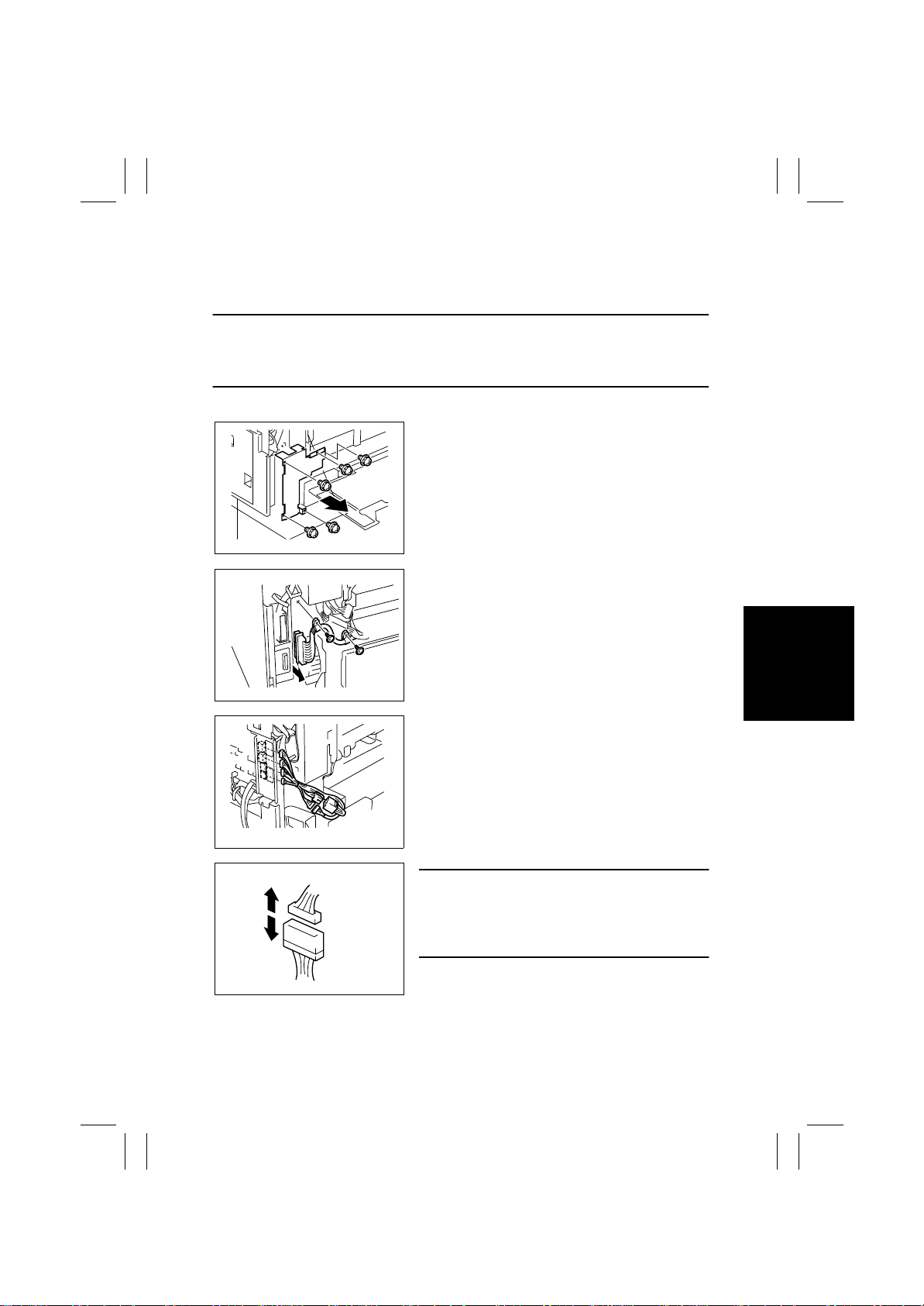
1. Open the Front Door.
2. Sl i d e out the IU (C, M, Y, Bk).
NOTES
• After the IU has been pulled out, place the IU lock lever back into the locked position.
• When sliding the IU back in, make sure that the shutter is opened if the IU Lower Cover is
not to be used.
3. Removed the Rear Left Cover.
4. Remove five screws and the harness protective
metal bracket.
4004D229AA
5. Remove two screws and unplug one connector
on the PIC Board.
A
B
4025D142AA
6. Unplug four connectors from the IO Board.
7. Disconnect two hookup connectors.
4025D031AB
NOTE
• When unplugging the connector, make sure that
connector A (on the copier side) is disconnected.
Connector B (on the LPH Unit side) should not be
disconnected.
40004D232AA
D-17
Page 20
FrameMaker Ver.5.5E(PC) 8020/8031 DIS/REASSEMBLY, ADJUSTMENT
02.08.19
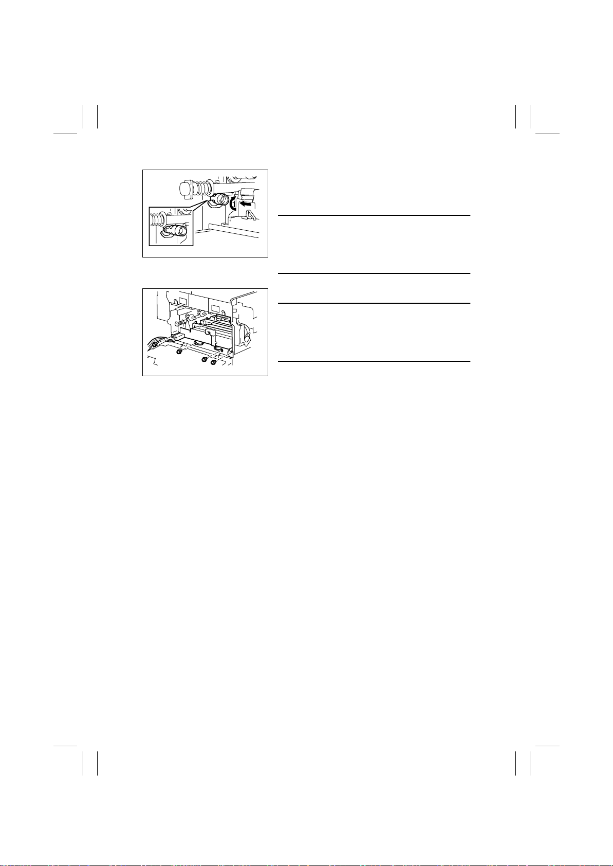
8. Open the Right Door and Left Door and remove
the Waste Toner Bottle and Transfer Belt Unit.
9. Turning the IU (C , M, Y, Bk) drive hub, push it into
the locked position (at four places).
NOTES
• During the locking procedure, use care not to
4004D024AA
touch the LED surface.
• Should the LED surface be touched, clean it with
the LED Cleaning Jig.
10. Remove four screws and slide out the LPH Unit.
NOTE
• When the LPH Unit is to be replaced, remove the
ATDC Sensor from the old LPH Unit and remount it
on the new one. This step is not, however, necessary if the IU is replaced at the same time.
4025D032AA
D-18
Page 21
FrameMaker Ver.5.5E(PC) 8020/8031 DIS/REASSEMBLY, ADJUSTMENT
02.08.19
2-4. Disassembly of the IR Unit
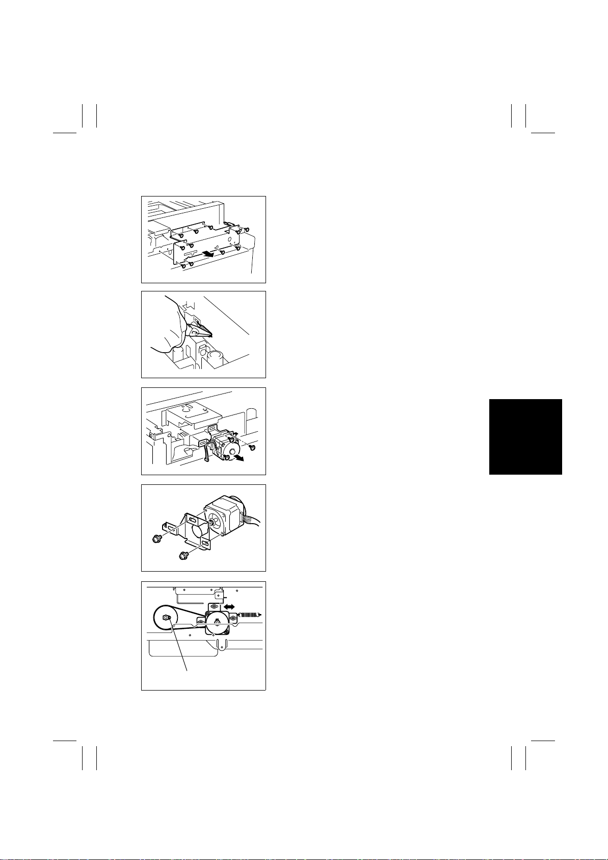
(1) Removal of the Scanner Motor
1. Remove the IR Rear Cover.
2. Remove 11 screws and the reinforcement frame.
4025D033AA
3. Remove the tension spring for the Scanner Motor
timing belt.
4025D034AA
4. Remove three screws and the Scanner Motor
Assy.
screw
4025D036AA
4025D037AA
4025D132AA
5. Remove two screws and the Scanner Motor.
<Reinstallation of the Scanner Motor Assy>
1. Temporarily secure the Scanner Motor Assy
using three screws.
2. Hook the spring.
3. With the Scanner drive gear set screw located on
the right-hand side as shown on the left, slide the
Scanner Motor Assy to the left and check that it is
returned to the original position by the tension of
the spring. Perform this step three times.
4. Securely tighten the three screws to fix the Scanner Motor Assy into position.
D-19
Page 22
FrameMaker Ver.5.5E(PC) 8020/8031 DIS/REASSEMBLY, ADJUSTMENT
02.08.19
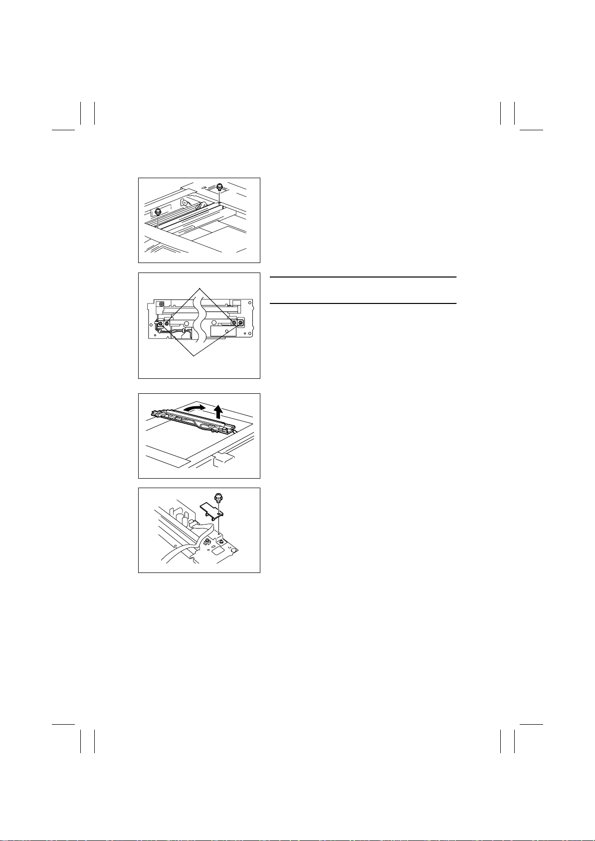
(2) Remove of the Scanner Assy
1. Remove the Original Glass.
2. Move the Scanner Assy to the location shown
and remove one mounting screw each at the front
and rear end.
4004D202AA
Scanner mounting Screws
Scanner positioning
Screws
NOTE
• Do not remove the Scanner Positioning Screw.
4025D038AA
3. Take out the Scanner Assy by turning it in the
direction of the arrow shown.
4004D017AB
4. Remove one screw and the holder.
5. Remove the flat cable.
6. Remove the Scanner Assy.
4025D039AA
D-20
Page 23
FrameMaker Ver.5.5E(PC) 8020/8031 DIS/REASSEMBLY, ADJUSTMENT
02.08.19
(3) Removal of the Scanner Drive Cables
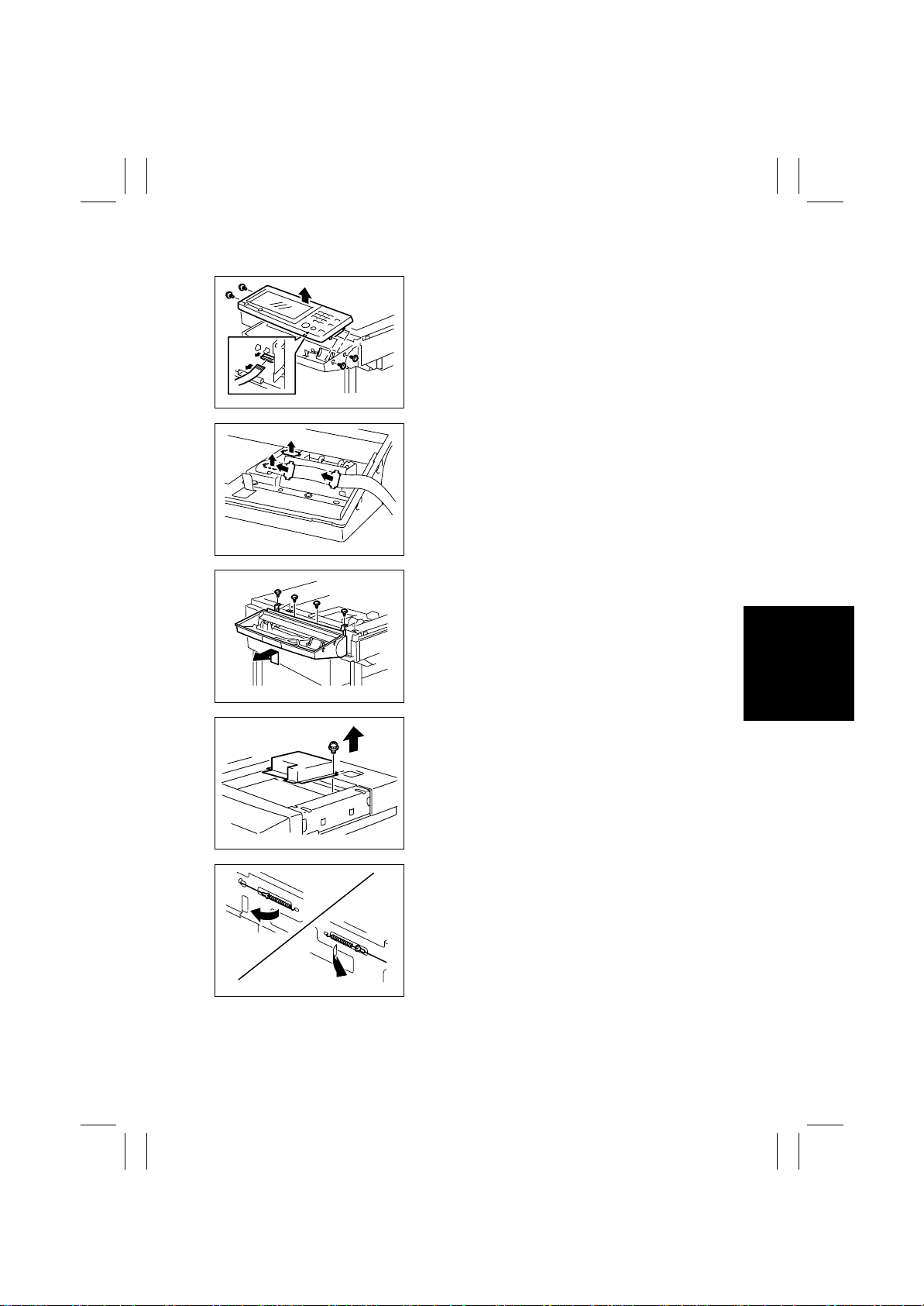
1. Remove the IR Rear Cover.
2. Remove four screws and Control Panel.
4025D042AA
3. Remove the holding bracket and flat cable.
4025D041AB
4. Remove four screws and the control panel base.
4025D040AA
4025E006AB
4002D110AB
5. Remove the IR Front Cover.
6. Remove the Original Glass.
7. Remove 14 screws and the Optical Cover.
8. Remove the Scanner Assy.
☞
D-20
9. Remove the IR Right Cover and the IR Left
Cover.
10. Unhook the springs of the Scanner Drive Cables
on the hook side, one each at the front and in the
rear.
D-21
Page 24
FrameMaker Ver.5.5E(PC) 8020/8031 DIS/REASSEMBLY, ADJUSTMENT
02.08.19
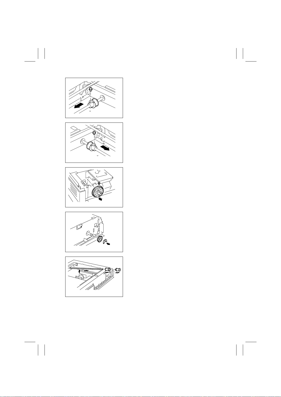
11. Remove the Scanner Motor Assy.
☞
D-19
12. Remove one screw and then slide the front pulley
toward the front.
4002D112AA
13. Remove one screw and then slide the rear pulley
toward the front.
4002D113AA
14. Remove one screw and the Scanner drive gear.
4025D043AA
4025D044AA
4025D045AA
15. Snap off the C-clip and remove the bushing
(front).
16. Slide the shaft toward the rear and lift it. Then,
remove the front and rear pulleys.
17. Remove the Scanner Drive Cables.
D-22
Page 25
FrameMaker Ver.5.5E(PC) 8020/8031 DIS/REASSEMBLY, ADJUSTMENT
02.08.19
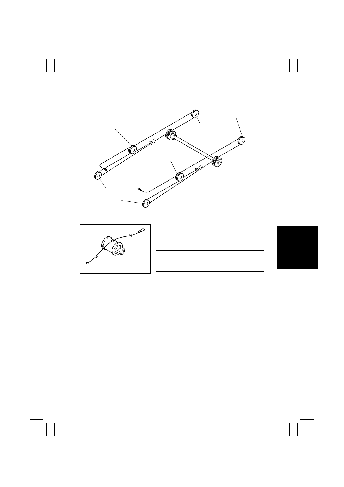
(4) Winding of the Scanner Drive Cables
Pulley C
Pulley E
Pulley D
Pulley A
4025D046AA
Pulley F
Pulley B
4025D045AA
Front
1. Position the round bead of the Scanner Drive
Cable in the pulley as shown.
NOTE
• Make sure that the bead snugly rests in the slit in
the pulley.
D-23
Page 26
FrameMaker Ver.5.5E(PC) 8020/8031 DIS/REASSEMBLY, ADJUSTMENT
02.08.19
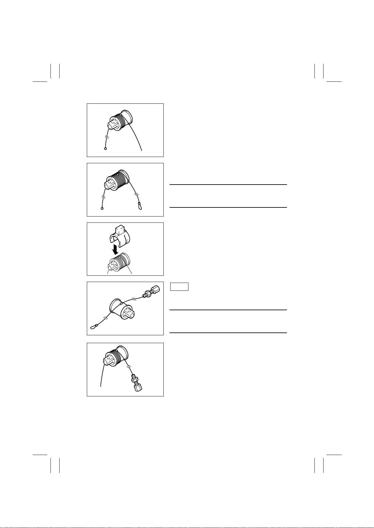
2. Wind the fixed bead end of the cable around the
pulley five turns clockwise, from the rear toward
the front side.
4025D047AA
3. Wind the hook end of the cable around the pulley
five turns counterclockwise, from the front toward
the rear side.
NOTE
• Make sure that no part of the cable rides on the
other.
4025D048AA
4. Slip the Cable Holding Jig onto the pulley to
secure the cable in position.
4025D049AA
4025D051AA
4025D052AA
Rear
5. Position the round bead of the Scanner Drive
Cable in the pulley as shown.
NOTE
• Make sure that the bead snugly rests in the slit in
the pulley.
6. Wind the fixed bead end of the cable around the
pulley five turns clockwise, from the front toward
the rear side.
D-24
Page 27
FrameMaker Ver.5.5E(PC) 8020/8031 DIS/REASSEMBLY, ADJUSTMENT
02.08.19
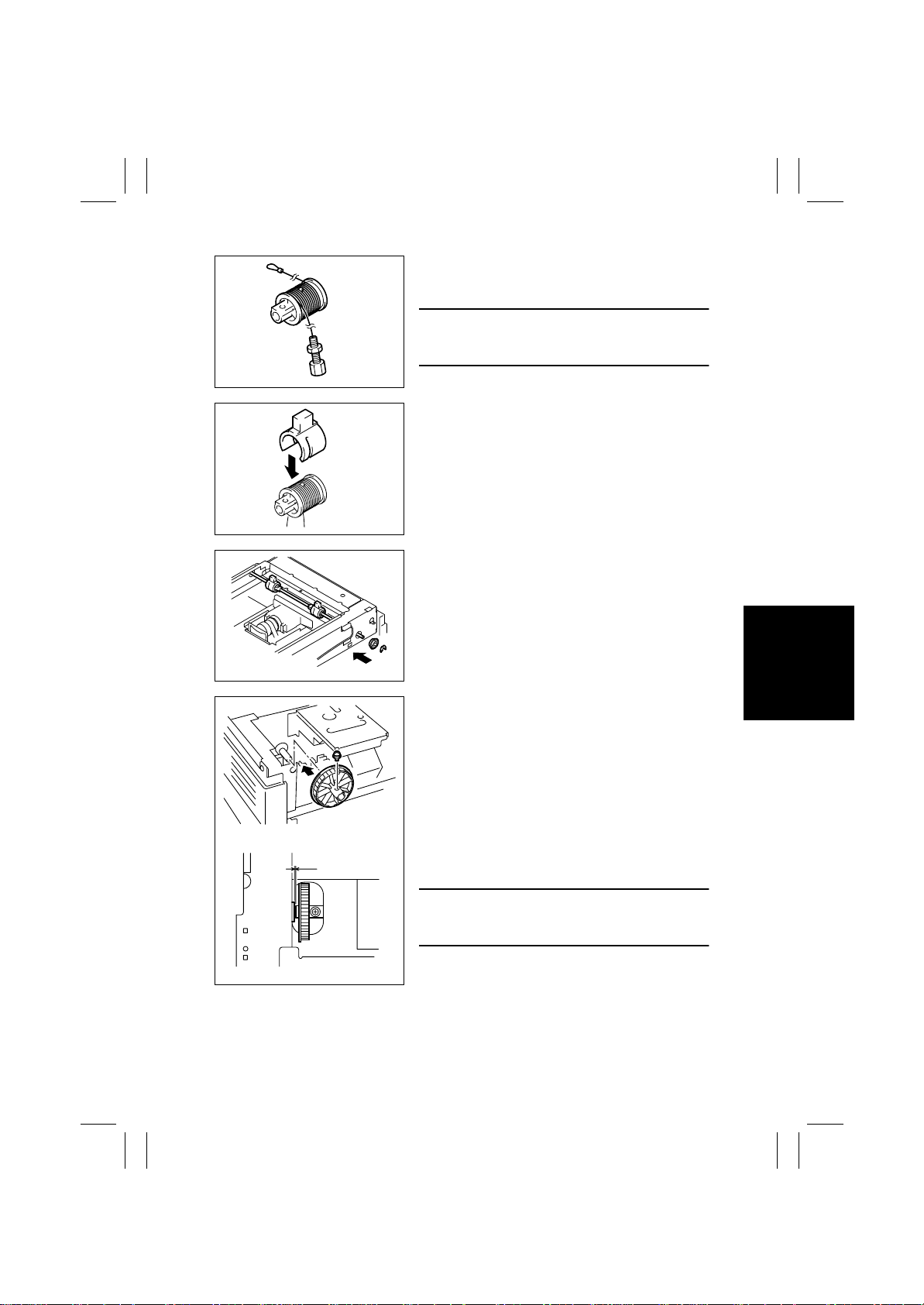
7. Wind the hook end of the cable around the pulley
five turns counterclockwise, from the rear toward
the front side.
NOTE
• Make sure that no part of the cable rides on the
other.
4025D053AB
8. Slip the Cable Holding Jig onto the pulley to
secure the cable in position.
4025D054AB
9. Install the front and rear pulleys and bushings
onto the shaft and fit the C-clip.
0.1 mm
4025D056AA
10. Mount the Scanner drive gear on the shaft and
secure it using one screw.
4025D057AA
NOTE
• Allow a clearance of about 0.1 mm between the
Scanner drive gear and bushing.
4025D059AA
D-25
Page 28
FrameMaker Ver.5.5E(PC) 8020/8031 DIS/REASSEMBLY, ADJUSTMENT
02.08.19
11. Secure the front and rear pulleys using one screw
each.
4025D058AA
12. Mount the Scanner Motor Assy.
☞
D-19
4025D117AA
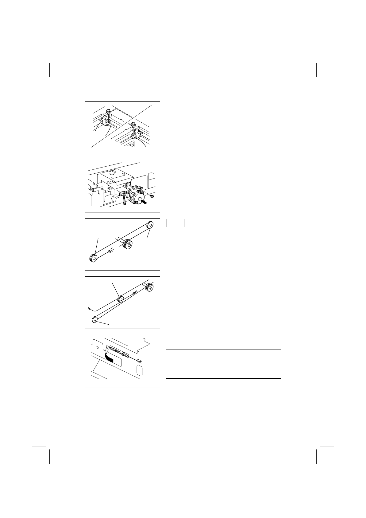
Front
Pulley B
Pulley C
13. Wind the bead end of the cable around pulley C
and pulley B, then hook the bead onto the Adjustable Anchor.
Pulley B
Pulley A
4002D008AA
14. Wind the hook end of the cable around pulley A
and pulley B.
4002D009AA
15. Fit the hook end of the cable to the spring and
then hook the spring to the catch in the frame.
NOTE
• Select the appropriate catch in the frame (from
among three) so that the spring measures 64.2
mm ±1 mm.
4002D119AB
D-26
Page 29
FrameMaker Ver.5.5E(PC) 8020/8031 DIS/REASSEMBLY, ADJUSTMENT
02.08.19
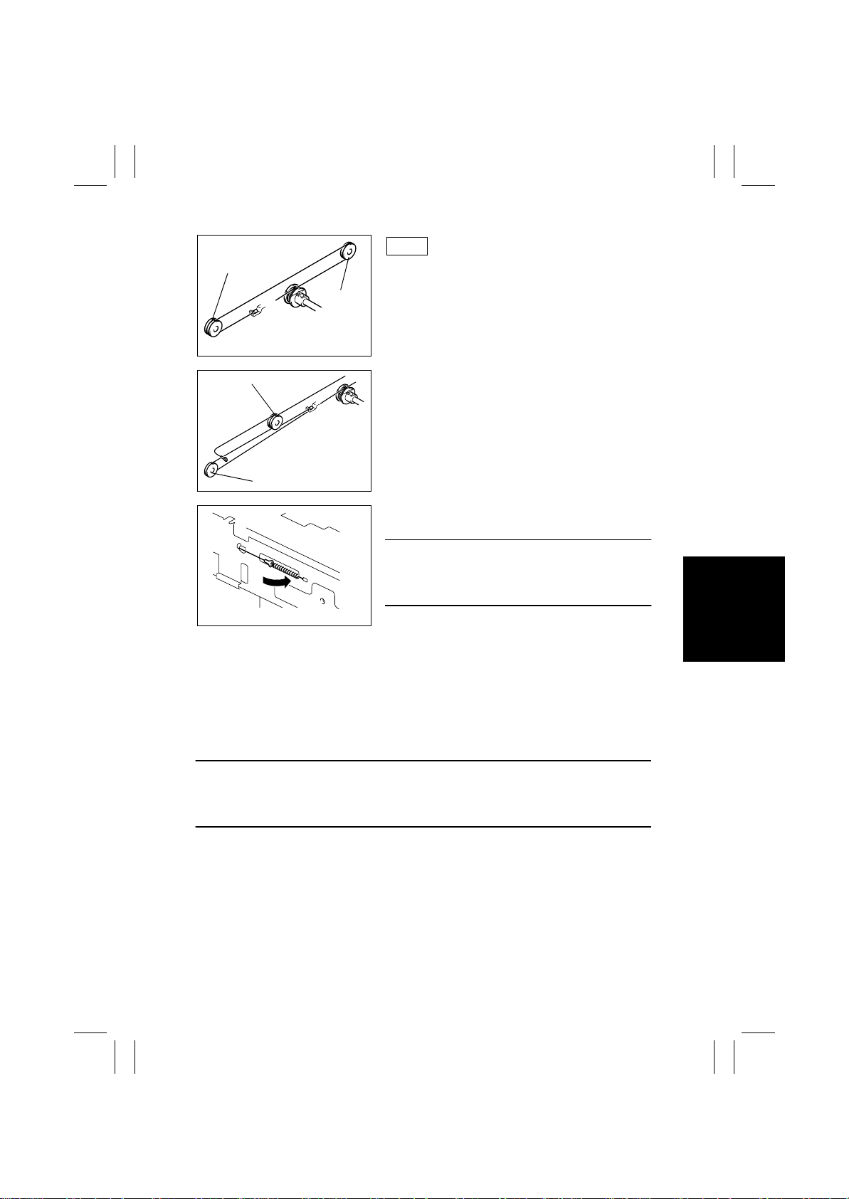
Rear
Pulley E
16. Wind the bead end of the cable around pulley F
and pulley E, then hook the bead onto the Adjust-
Pulley F
4002D010AA
able Anchor.
Pulley E
Pulley D
4002D011AA
and pulley E.
18. Fit the hook end of the cable to the spring and
then hook the spring to the catch in the frame.
NOTE
• Select the appropriate catch in the frame (from
among three) so that the spring measures 64.2
mm ±1 mm.
17. Wind the hook end of the cable around pulley D
4002D120AB
19. Remove the Cable Holding Jigs from the front and r ear pulleys.
20. Mount the Scanner Assy and Flat Cable.
21. Reinstall the optical cover.
22. Reinstall the Original Glass.
23. Reinstall all covers which have been removed.
24. Reinstall the Control Panel.
25. Adjust the position of the Scanner and 2nd/3rd Mirrors Carriage.
☞
D-44
NOTE
• Whenever the Scanner Drive Cables have been removed, be sure to carry out the “FDMag” adjustment procedure.
☞
D-68
D-27
Page 30
FrameMaker Ver.5.5E(PC) 8020/8031 DIS/REASSEMBLY, ADJUSTMENT
02.08.19
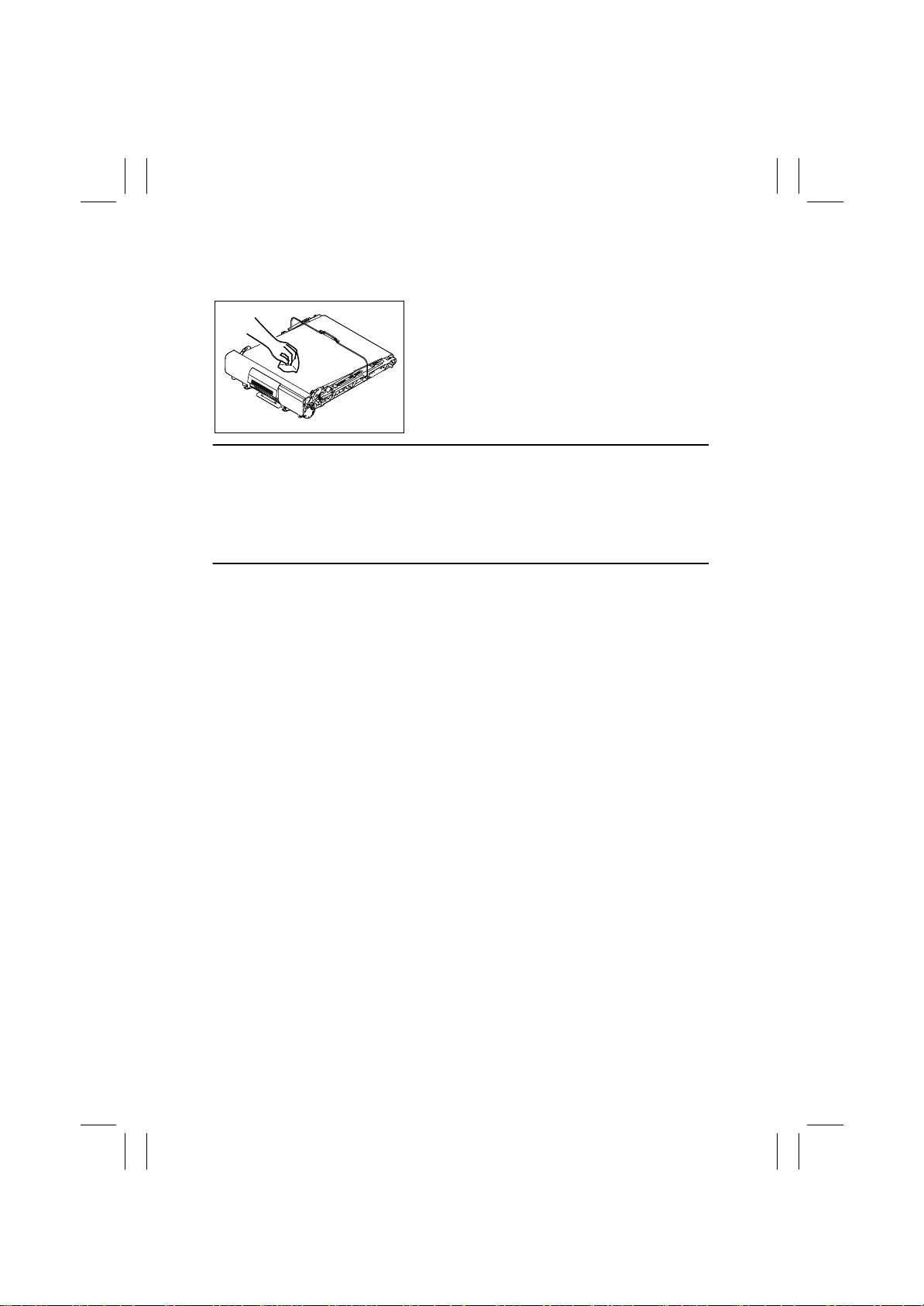
2-5. CLEANING AND DISASSEMBLY OF THE ENGINE PARTS
(1) Cleaning of the Transfer Belt Unit
1. Remove the Transfer Belt Unit.
☞
Maintenance Schedule Section
2. Wipe the surface of the Transfer Belt with a dry
cloth.
4004D228AA
NOTES
• If the dry cloth is not effective in removing dirt, dampen it with alcohol.
• Do not use a cloth wet with water.
• If any solvent is to be used, select one f rom among the following:
IPA, ethyl alcohol, PPC Cleaner, and Solmix AP-7.
• When the solvent has been used for cleaning, make 28 or more copies using A3 blank
sheets of paper to remove image noise.
D-28
Page 31
FrameMaker Ver.5.5E(PC) 8020/8031 DIS/REASSEMBLY, ADJUSTMENT
02.08.19
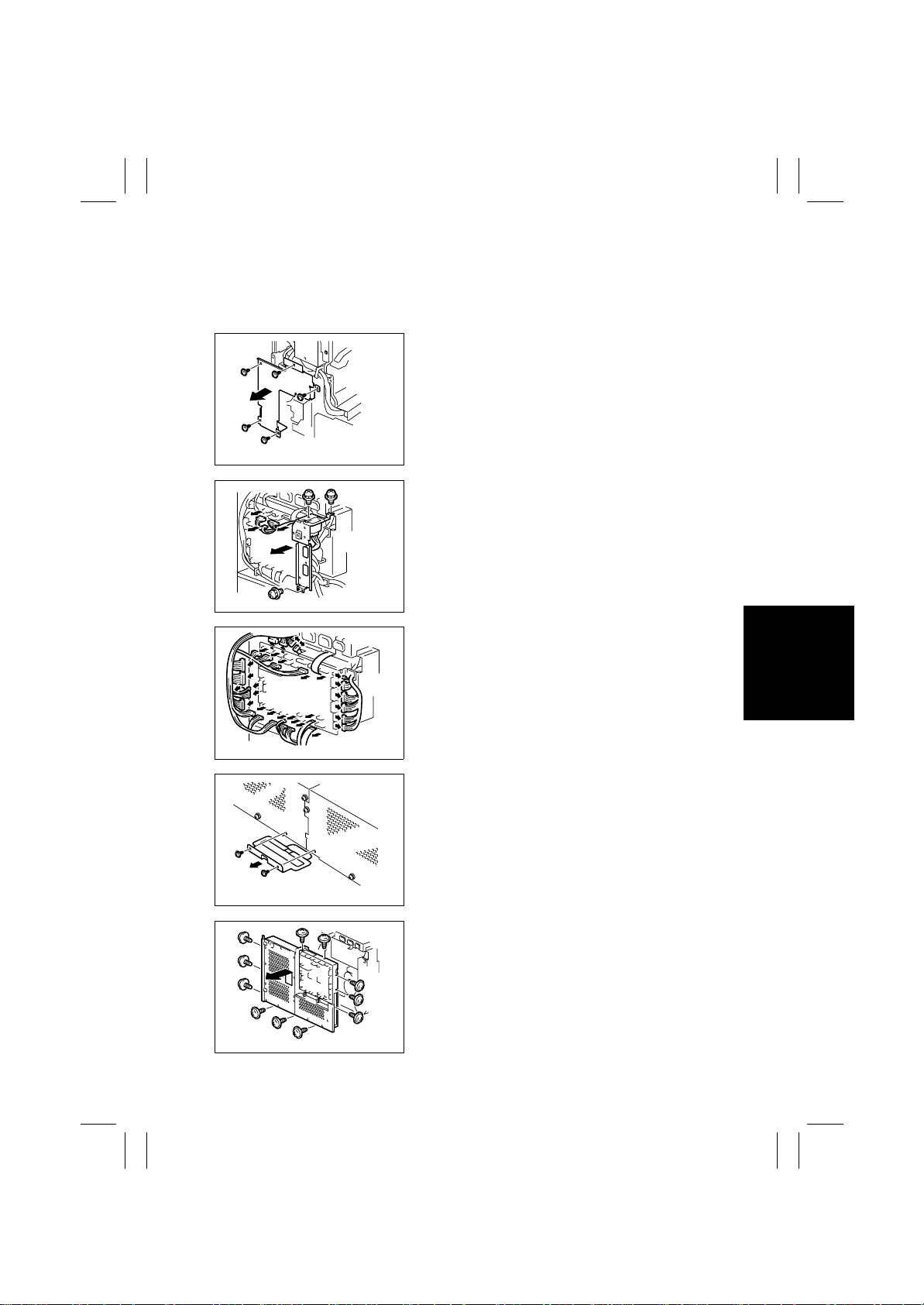
(2) Removal of the Imaging Unit Motor C/M/Y/Bk
1. Remove the Rear Upper Cover.
2. Remove the Rear Left Cover.
3. Remove the Rear Right Cover.
4. Remove five screws and the harness protective
metal bracket.
4025D015AA
5. Remove three screws, unplug three connectors,
and remove the rear left metal bracket.
4025D017AA
4025D016AA
4025D018AA
4025D019AA
6. Unplug all connectors of the IO Board.
7. Unplug two connectors of the Option Interface
Board.
8. Unplug two connectors of the PIC Board.
9. Remove two screws and the power line mounting
bracket for the 2nd Drawer.
10. Remove 11 screws and lift the PWB box upward
and off the copier.
D-29
Page 32
FrameMaker Ver.5.5E(PC) 8020/8031 DIS/REASSEMBLY, ADJUSTMENT
02.08.19
11. Remove the LPH Unit.
☞
D-17
12. Unplug two connectors.
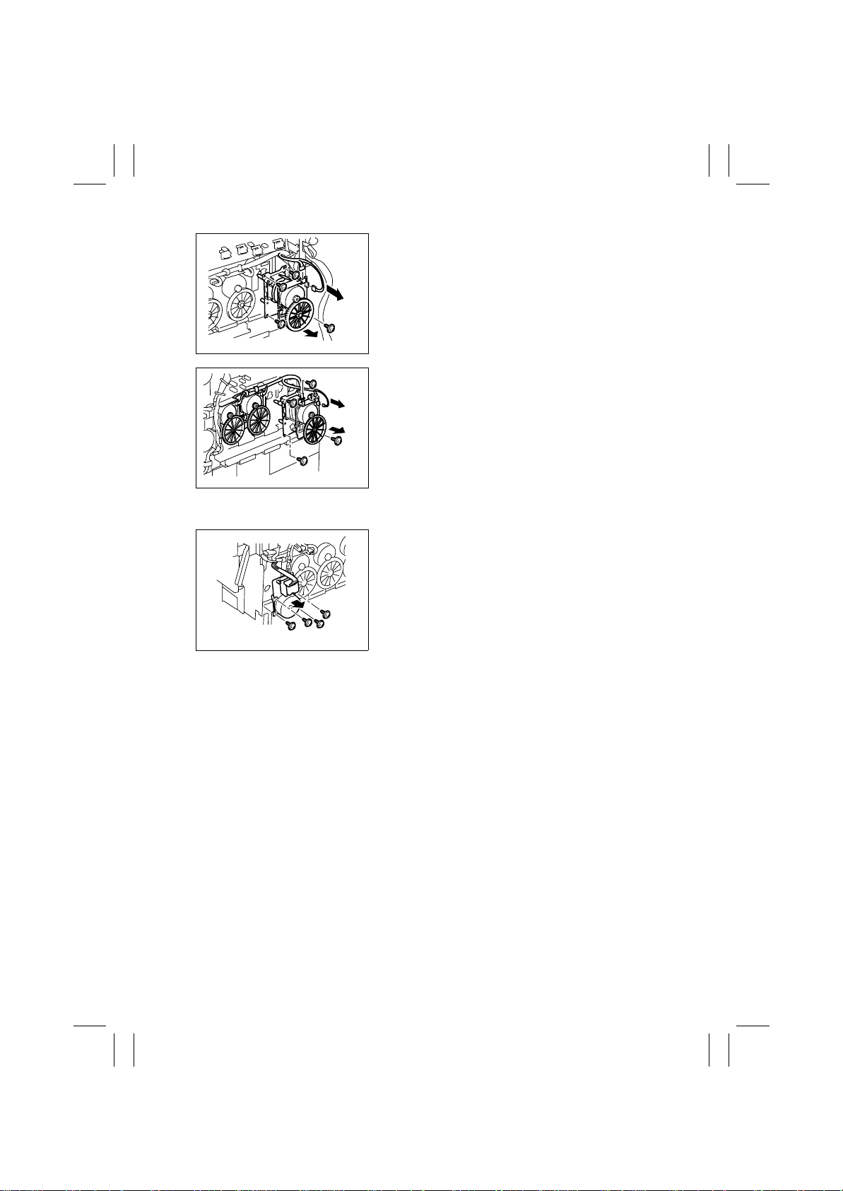
13. Remove four screws and Imaging Unit Motor Y.
4025D135AA
14. Unplug two connectors each.
15. Remove four screws each and Imaging Unit
Motor M/C/Bk.
4025D136AA
(3) Removal of the Main Motor
1. Remove t he PWB Box.
☞
D-13 (steps 1 through 10)
2. Unplug one connector.
3. Remove four screws and the Main Motor.
4004D060AA
D-30
Page 33
FrameMaker Ver.5.5E(PC) 8020/8031 DIS/REASSEMBLY, ADJUSTMENT
02.08.19
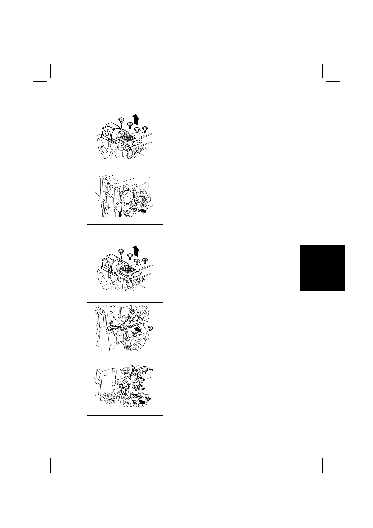
(4) Removal of the Fusing Drive Motor
1. Remove t he PWB Box.
☞
D-13 (steps 1 through 10)
2. Remove four screws and the Cooling Fan Assy.
4025D060AA
3. Unplug one connector.
4. Remove four screws and the Fusing Drive Motor.
4004D062AB
(5) Removal of the Fusing Pressure/Retraction Motor
4025D060AA
4004D063AA
4004D064AA
1. Remove t he PWB Box.
☞
D-13 (steps 1 through 10)
2. Remove four screws and the Cooling Fan Assy.
3. Remove two screws and the harness holder.
4. Unplug two connectors.
5. Remove three screws and the Fusing Pressure/
Retraction Motor Assy.
D-31
Page 34
FrameMaker Ver.5.5E(PC) 8020/8031 DIS/REASSEMBLY, ADJUSTMENT
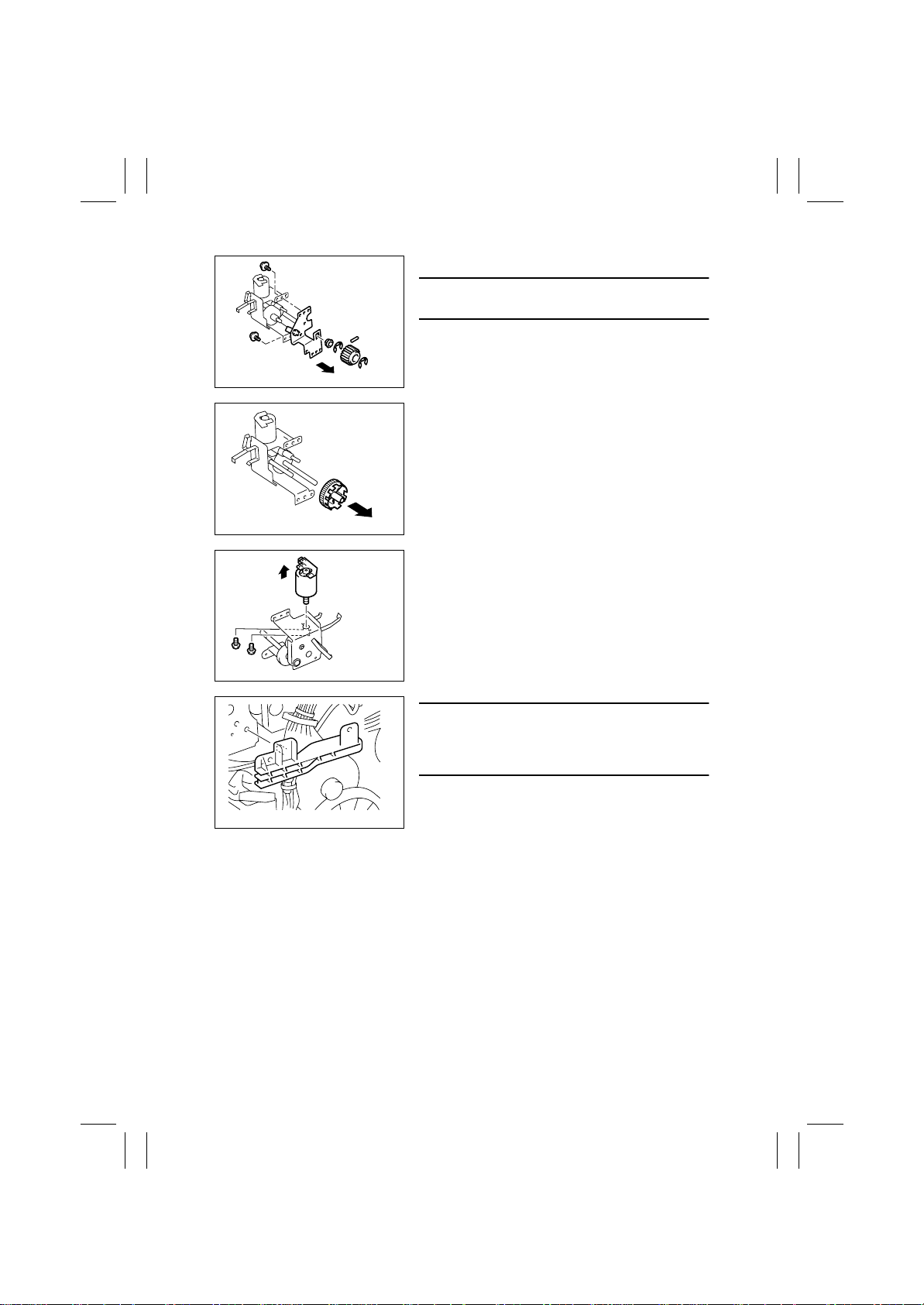
02.08.19
6. Snap off one E-ring and remove the gear and pin.
NOTE
• Use care not to lose the pin.
7. Snap off one E-ring and remove the bushing.
8. Remove two screws and the Fusing Retraction
Position Sensor mounting bracket.
4004D125AA
9. Remove the gear (black).
4004D209AA
10. Remove two screws and the Fusing Pressure/
Retraction Motor.
4004D126AB
4004D065AB
Precaution for Reinstallation
• When reinstalling the harness holder, make sure
that the protrusion on the backside of the holder
fits into the hole in the metal bra cket.
D-32
Page 35
FrameMaker Ver.5.5E(PC) 8020/8031 DIS/REASSEMBLY, ADJUSTMENT
02.08.19
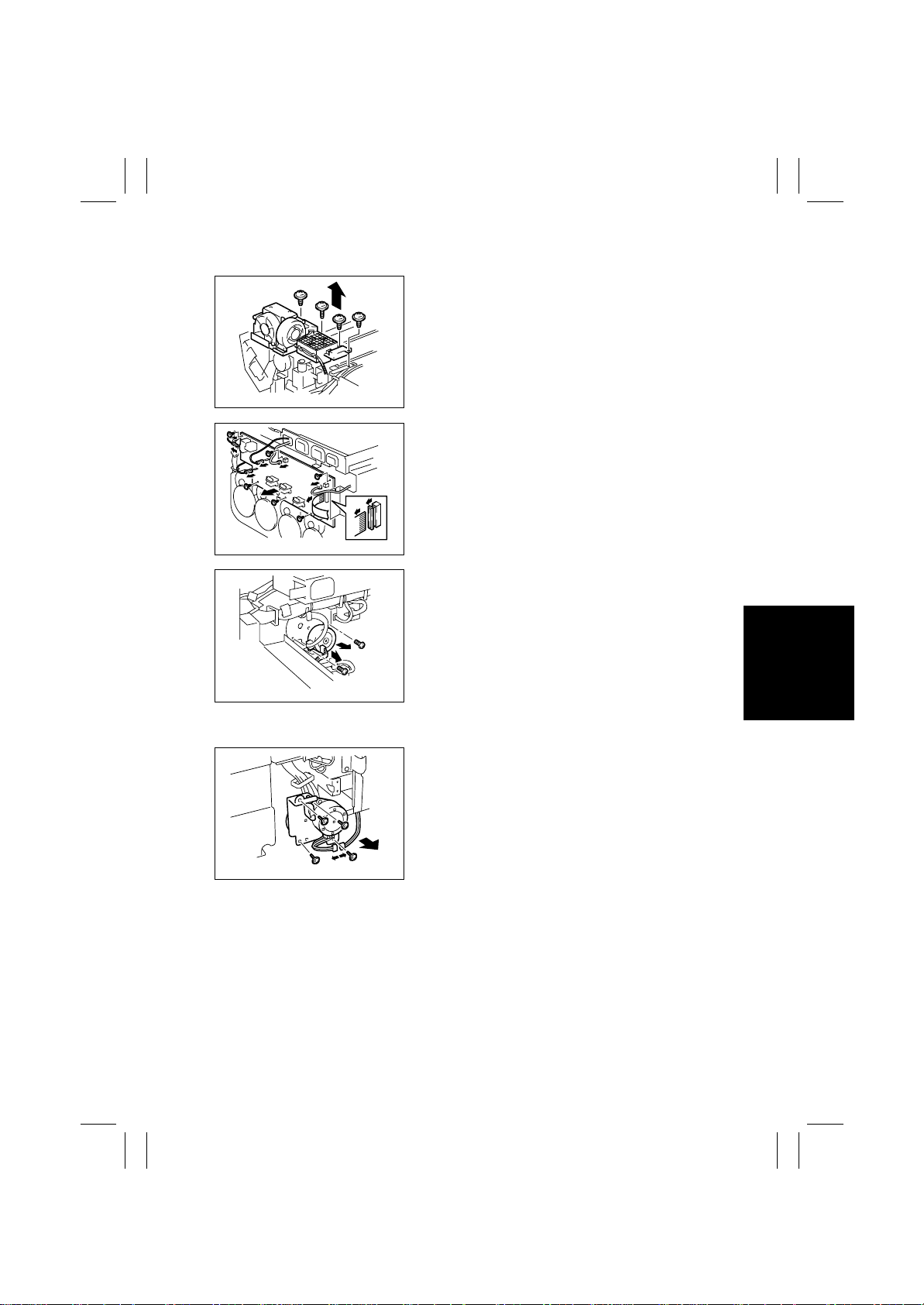
(6) Removal of the 1st Image Transfer Pressure/Retraction Motor
1. Remove t he PWB Box.
☞
D-13 (steps 1 through 10)
2. Remove four screws and the Cooling Fan Assy.
4025D060AA
3. Disconnect connectors, terminals, and flat cable.
4. Remove six screws and slide the High Voltage
Unit (Image Transfer, Neutralizing) to the left and
off the copier.
4025D020AA
5. Unplug one connector.
6. Remove two screws and the 1st Image Transfer
Pressure/Retraction Motor.
4004D069AA
(7) Removal of Toner Replenishing Motor C/Bk
1. Remove the Right Front Cover.
2. Unplug one connector.
3. Remove four screws and the Toner Replenishing
Motor C/Bk As sy.
4004D071AB
D-33
Page 36
FrameMaker Ver.5.5E(PC) 8020/8031 DIS/REASSEMBLY, ADJUSTMENT
02.08.19
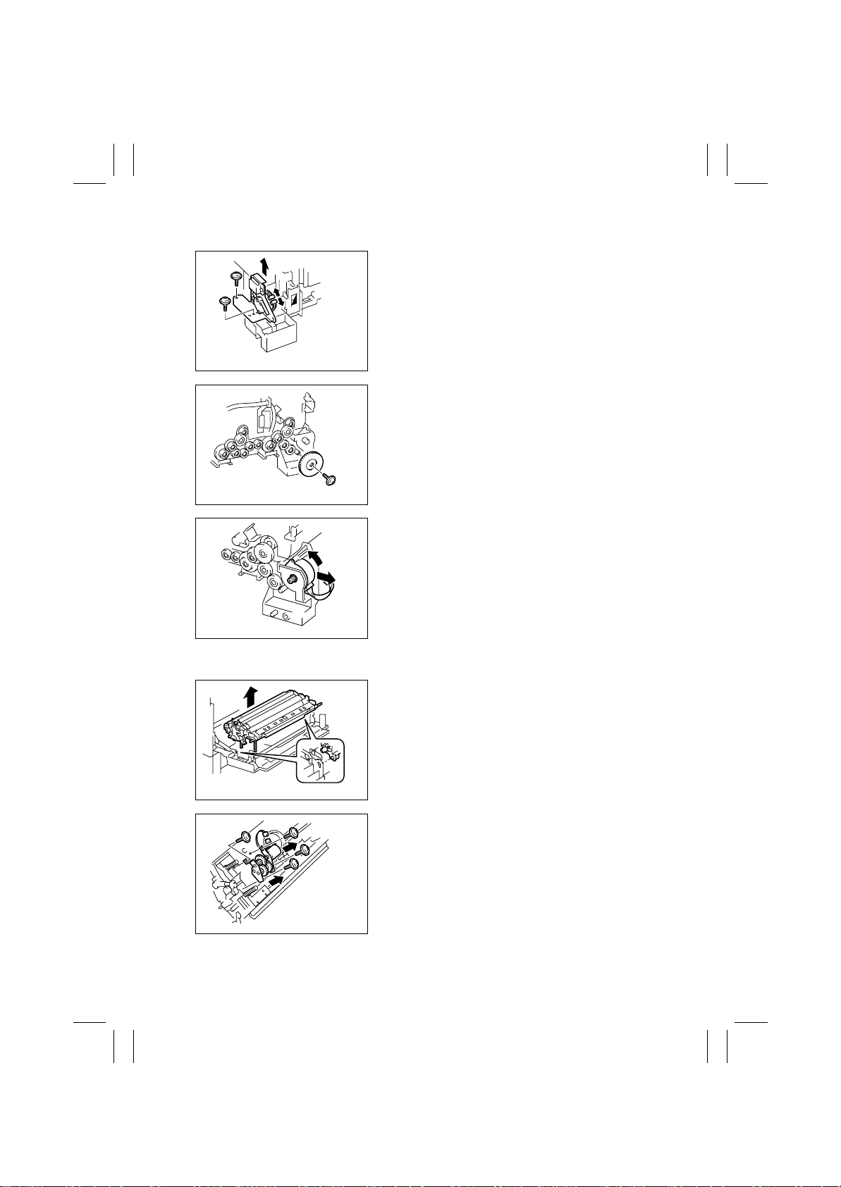
(8) Removal of Toner Replenishing Motor Y/M
1. Remove the Toner Hopper.
☞
D-16
2. Unplug one connector.
3. Remove two screws and the Front Door Switch
Assy.
4025D050AA
4. Remove one screw and the gear.
4025D055AA
5. Remove two screws. Then, turn the Toner
Replenishing Motor Y/M counterclockwise and
take it off the copier.
4025D061AA
(9) Removal of the 2nd Image Transfer Pressure/Retraction Motor
1. Open the Right Door.
2. Unlock the tab and remove the Transport Unit
Assy.
4025D062AA
3. Remove four screws, unplug one connector, and
remove the gear assy and motor assy.
4025D063AA
D-34
Page 37
FrameMaker Ver.5.5E(PC) 8020/8031 DIS/REASSEMBLY, ADJUSTMENT
02.08.19
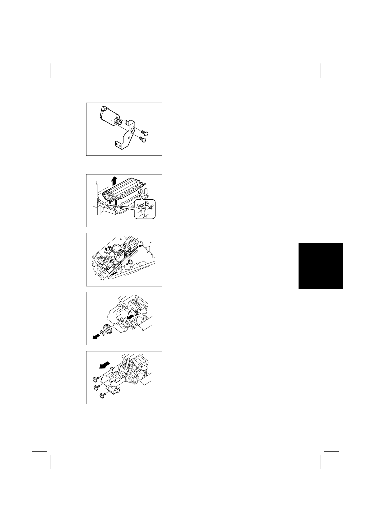
4. Remove two screws and the 2nd Image Transfer
Pressure/Retraction Motor.
4025D064AA
(10) Removal of the Transport Roller Motor
1. Open the Right Door.
2. Unlock the tab and remove the Transport Unit
Assy.
4025D062AA
3. Remove one screw, ground wire, and ground
plate.
4. Unplug five connectors and remove the Transport
Unit Assy.
4025D065AA
4025D066AA
4025D093AA
5. Snap off the C-clip and remove the gear.
6. Unhook the spring.
7. Remove three screws and the holder.
D-35
Page 38
FrameMaker Ver.5.5E(PC) 8020/8031 DIS/REASSEMBLY, ADJUSTMENT
02.08.19
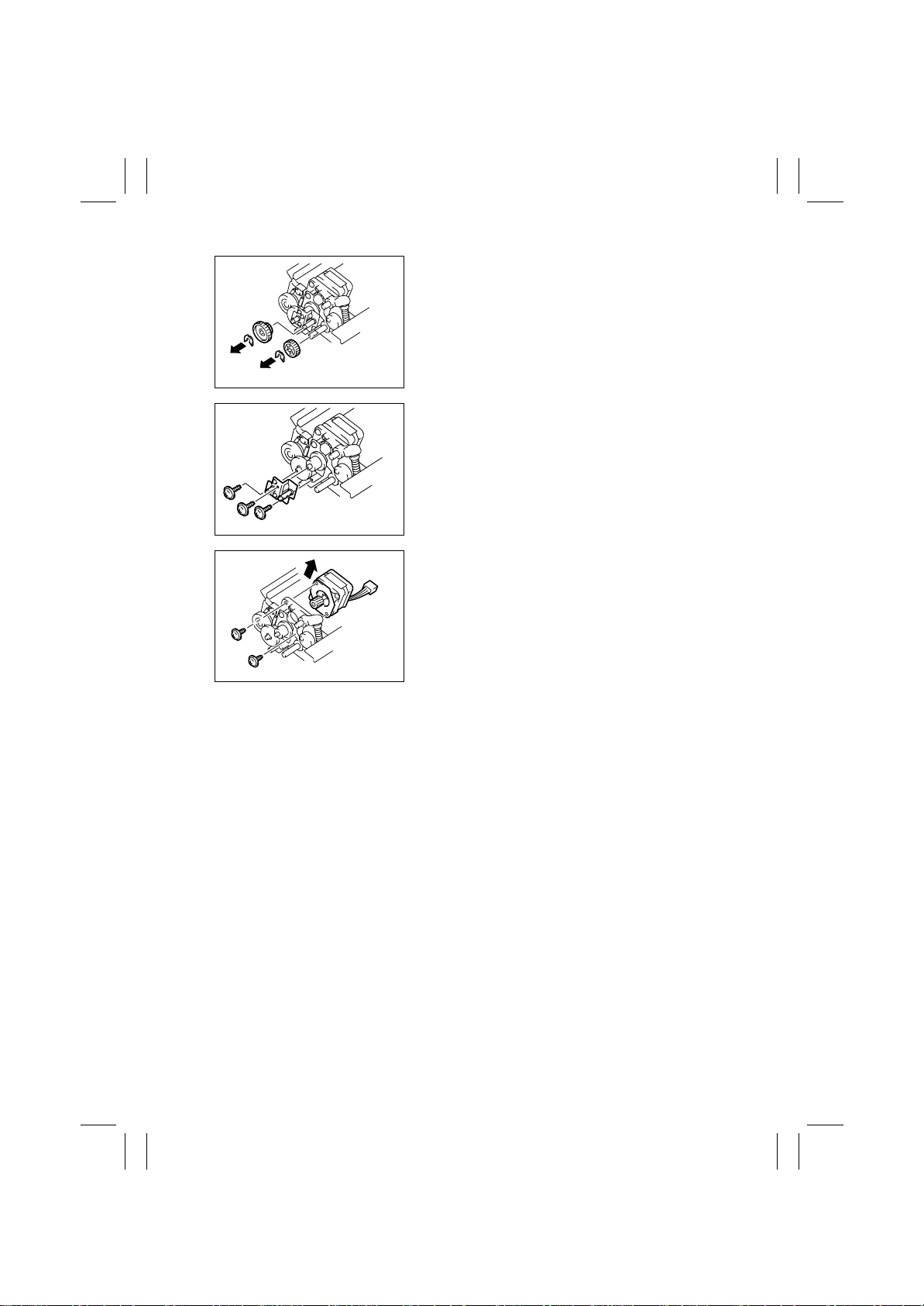
8. Snap off the C-clip and remove two gears.
4025D067AA
9. Remove three screws and the mounting bracket.
4025D068AA
10. Remove two screws and the Transport Roller
Motor.
4025D069AA
D-36
Page 39
FrameMaker Ver.5.5E(PC) 8020/8031 DIS/REASSEMBLY, ADJUSTMENT
02.08.19
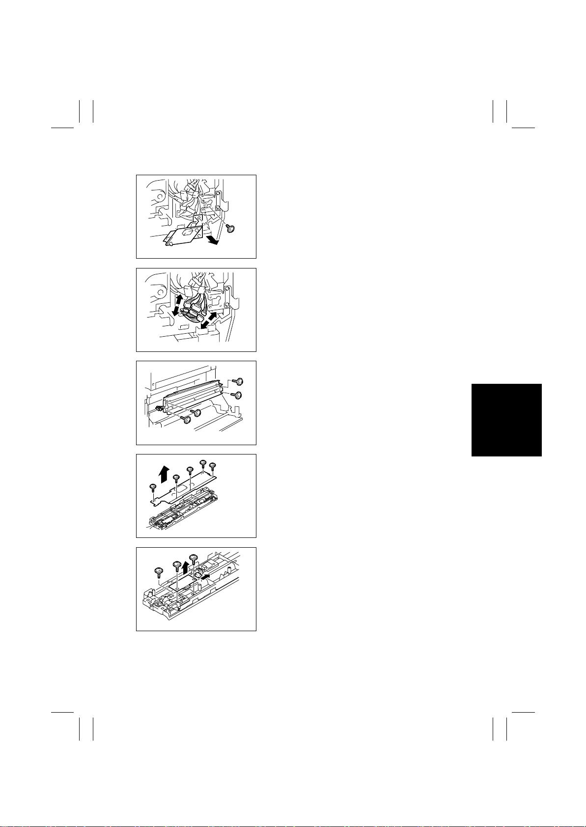
(11) Removal of AIDC/Registration Sensor 1/2
1. Remove the Front Right Door.
2. Remove one screw and the Tech. Rep. Setting
Switches Board Assy.
4025D070AA
3. Unplug three connectors
4025D071AA
4. Open the Right Door.
5. Remove four screws and the Synchronizing
Roller entrance guide.
4025D072AA
4025D073AA
4025D074AA
6. Remove five screws and the cover.
7. Remove three screws, unplug one connector , and
remove AIDC/Registration Sensor 1.
D-37
Page 40
FrameMaker Ver.5.5E(PC) 8020/8031 DIS/REASSEMBLY, ADJUSTMENT
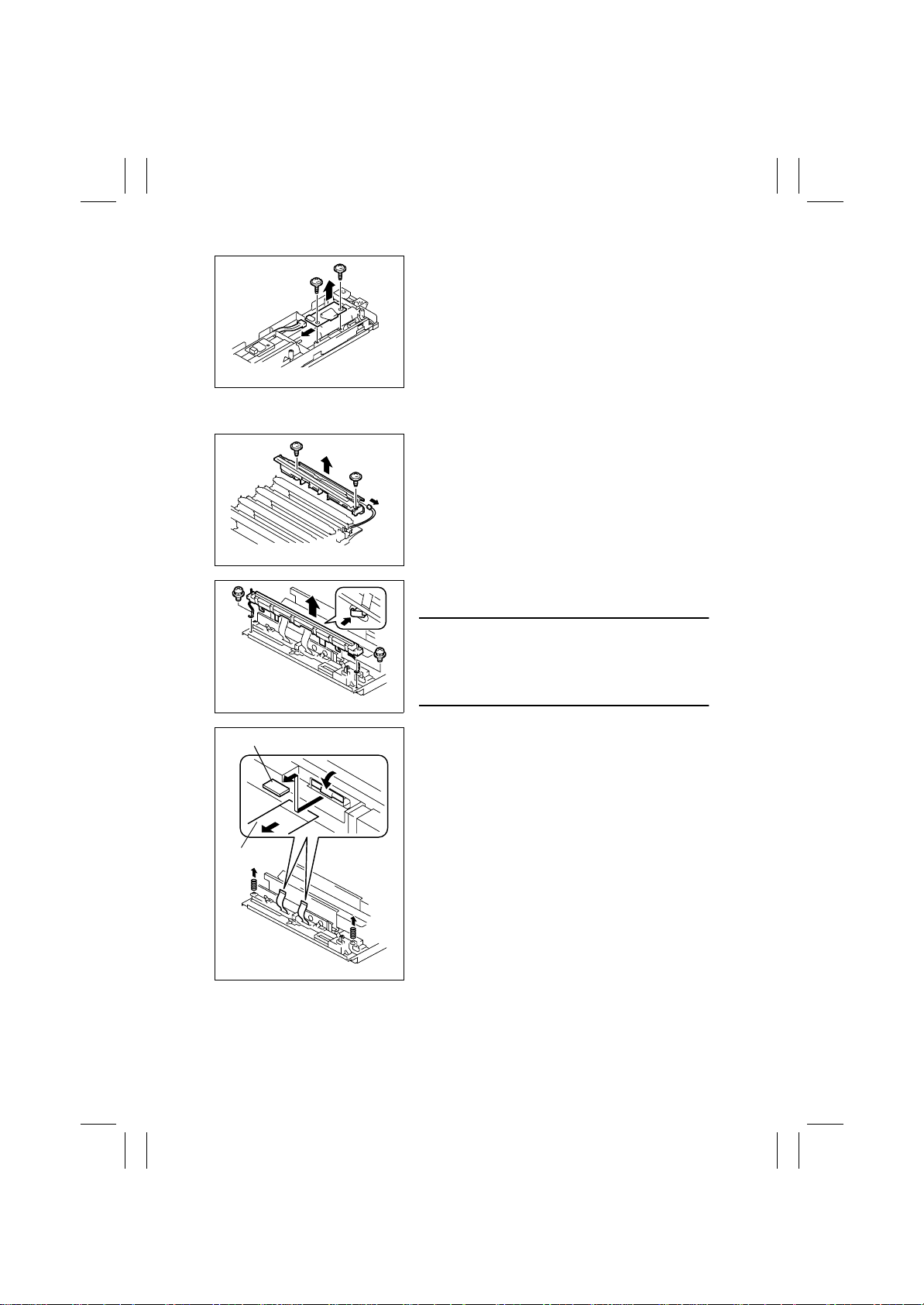
02.08.19
8. Remove two screws, unplug one connector, and
remove AIDC/Registration Sensor 2.
4025D075AA
(12) Removal of the LPH Assy
1. Remove the LPH Unit.
☞
D-17
2. Remove two screws, unplug one connector, and
remove the Guide Assy.
4025D076AA
3. Remove two screws and, holding the LPH Assy
with hands, unlock it.
Seal
Flat Cable
4025D077AA
4025D078AB
NOTES
• Do not touch the LED by hand. Clean the LED, if
touched by hand, using the LED cleaning jig.
• Be careful about the spring that can spring off
when the LPH Assy is unlocked.
4. Peel off the seal, unlock the LPH Assy, and
remove the flat cable.
5. Unhook the springs.
6. Perform the same procedure for each of different
colors of LPH Assy.
D-38
Page 41
FrameMaker Ver.5.5E(PC) 8020/8031 DIS/REASSEMBLY, ADJUSTMENT
02.08.19
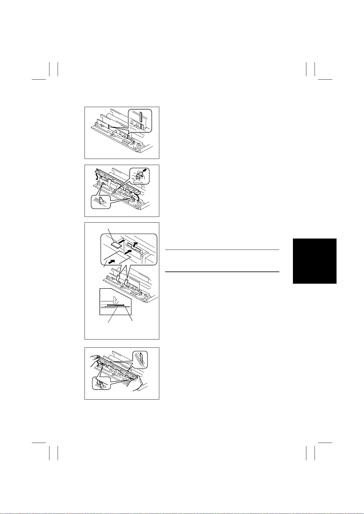
Reinstallation Procedure
1. Install the LPH Assy mounting jigs.
4025D079AA
2. Unlock the LPH Assy and place the pivot tabs (at
two places) at the upper position.
4025D081AA
Seal
Flat Cable
Double-Sided
Adhesive Tape
3. Insert the flat cable into the LPH Assy and lock
the LPH Assy.
4. Affix the seal that comes with the LPH Assy to
the location shown on the left.
NOTE
• Failure to affix the seal could cause the flat cable to
come off the LPH Assy.
Seal
Flat Cable
4025D080AB
5. Holding onto both ends of the LPH Assy , align the
portions shown on the left and then press it down
into the locked position.
4025D082AA
D-39
Page 42
FrameMaker Ver.5.5E(PC) 8020/8031 DIS/REASSEMBLY, ADJUSTMENT
02.08.19
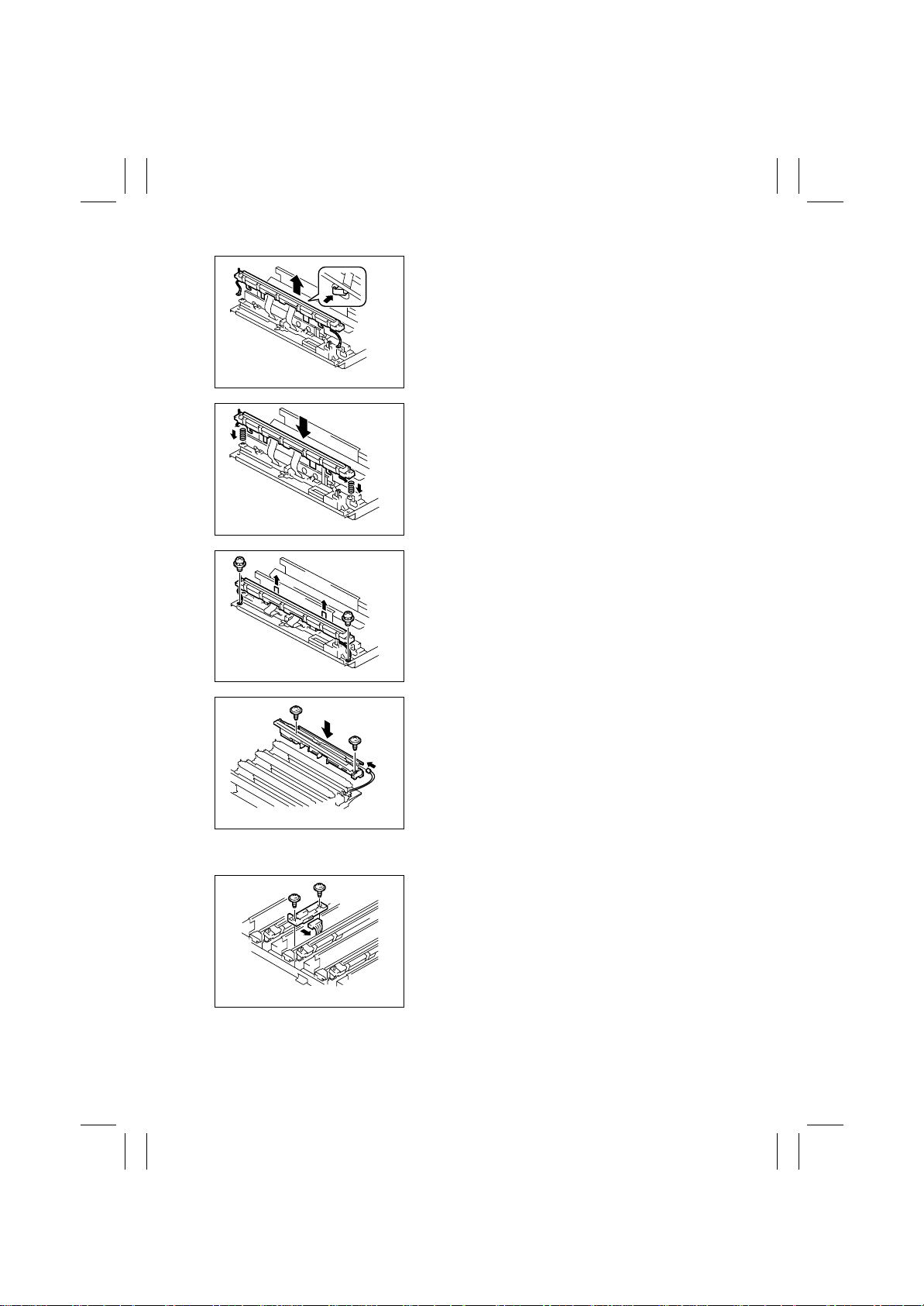
6. Unlock the LPH Assy.
4025D084AA
7. Hook the springs and press the LPH Assy down
into the locked position.
4025D085AA
8. Remove the LPH Assy mounting jigs.
9. Install the two screws.
4025D083AA
4025D087AA
(13) Removal of ATDC Sensor Y/ M/ C
4025D088AA
10. Install the two screws to secure the guide assy.
11. Connect the connector.
1. Remove the LPH Unit.
☞
D-17
2. Remove two screws, unplug the connector, and
remove the ATDC Sens or.
D-40
Page 43
FrameMaker Ver.5.5E(PC) 8020/8031 DIS/REASSEMBLY, ADJUSTMENT
02.08.19
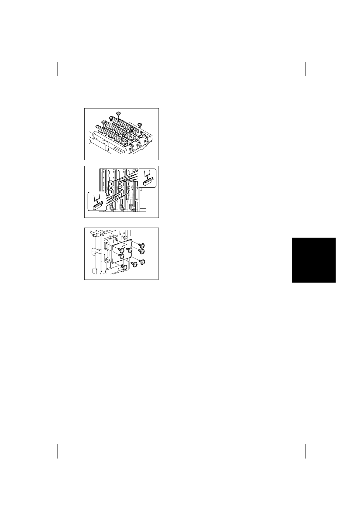
(14) Remov al of the LED Drive Board
1. Remove the LPH Unit.
☞
D-17
2. Remove two screws each, unplug one connector
each, and remove each guide assy.
4025D089AA
3. Remove the flat cables (eight).
4025D090AB
4. Remove eight screws, unplug two connectors,
and remove the LED Drive Board.
4025D092AA
D-41
Page 44
FrameMaker Ver.5.5E(PC) 8020/8031 DIS/REASSEMBLY, ADJUSTMENT
02.08.19
3. ADJUSTMENTS
• The adjustment procedures must be carried out in the order of printer and IR.
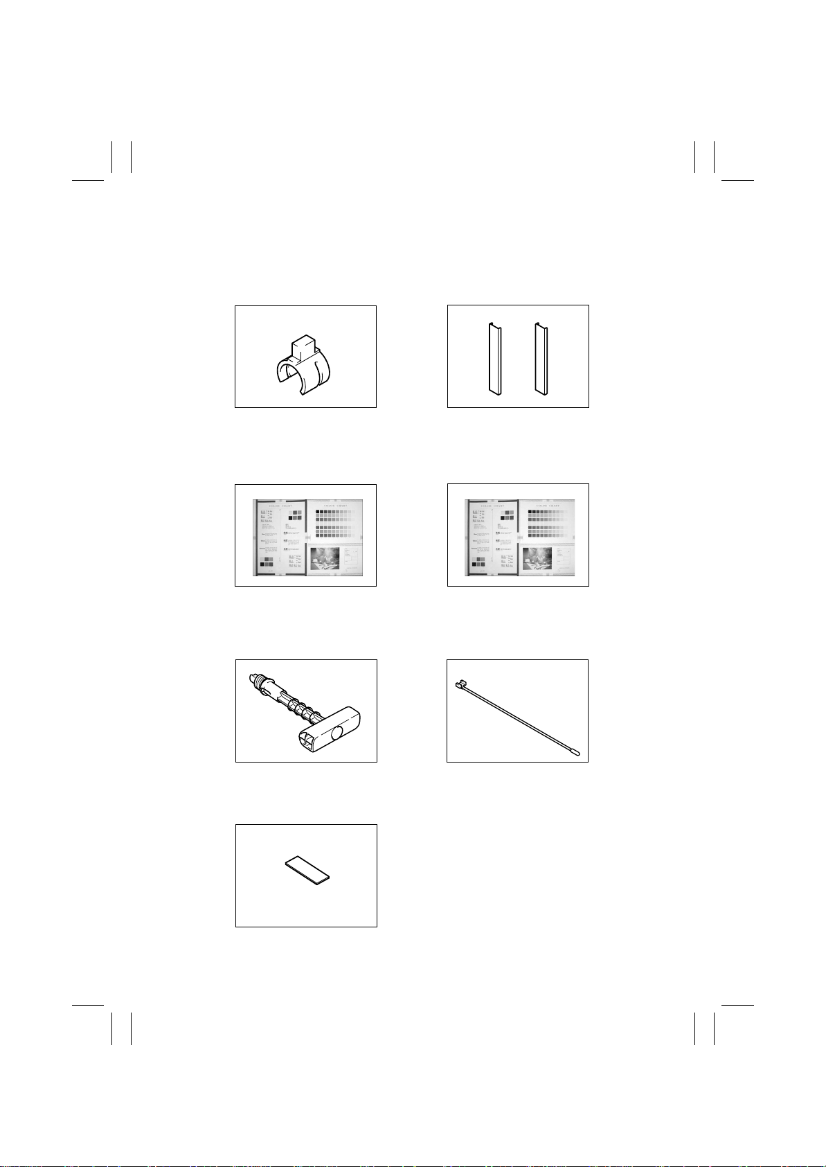
3-1. ADJUSTMENT JIGS AND TOOLS USED (SPECIAL TOOLS)
Part No. 65FA5111
Part No. 65FA5112
Scanner Drive Cable
Holding Jig
✽
✽
4025D118AA
Note1
Part No. 65FA9905
LPH Assy Mounting Jigs
✽
4025D121AA
Note2
Note1 The shapes of the parts differ between front and rear wires.
Note2 One pair is necessary for jig use though one piece is the spare part shipping unit.
Part No. 25TU0048
Test Chart (A3)
✽
Testchart
Part No. 111T9611
Test Chart (11×17)
✽
Testch ar t
3-2. OTHER TOOLS USED (ACCESSORY PARTS OF MACHINE)
Part No. 111T0013
✽
Part No. 111T5502
✽
4004D185AA
Imaging Unit Pull-out Jig
Part No. 111T5503
✽
4025D120AA
LED Cleaning Jig Pad
4004D186AA
LED Cleaning Jig
D-42
Page 45
FrameMaker Ver.5.5E(PC) 8020/8031 DIS/REASSEMBLY, ADJUSTMENT
02.08.19
3-3. MECHANICAL ADJUSTMENT
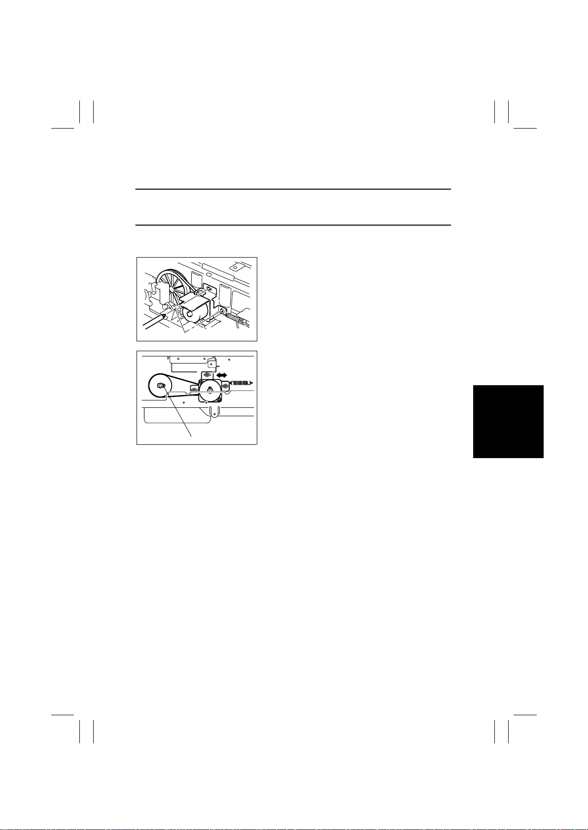
(1) Adjustment of the Scanner Motor Timing Belt
This adjustment must be made in the following case:
• The Scanner Motor Assy has been removed.
• The Scanner Drive Cables have been rewound.
1. Remove the IR Rear Cover.
2. Remove 11 screws and the reinforcement frame.
3. Loosen the three screws that secure the Scanner
Motor mounting bracket.
4004D188AC
4. With the Scanner drive gear set screw located on
the right-hand side as shown on the left, slide the
Scanner Motor Assy to the left and check that it is
returned to the original position by the tension of
the spring. Perform this step three times.
5. Tighten the three screws to fix the Scanner Motor
Assy into position.
4025D132AA
Set Screw
D-43
Page 46
FrameMaker Ver.5.5E(PC) 8020/8031 DIS/REASSEMBLY, ADJUSTMENT
02.08.19
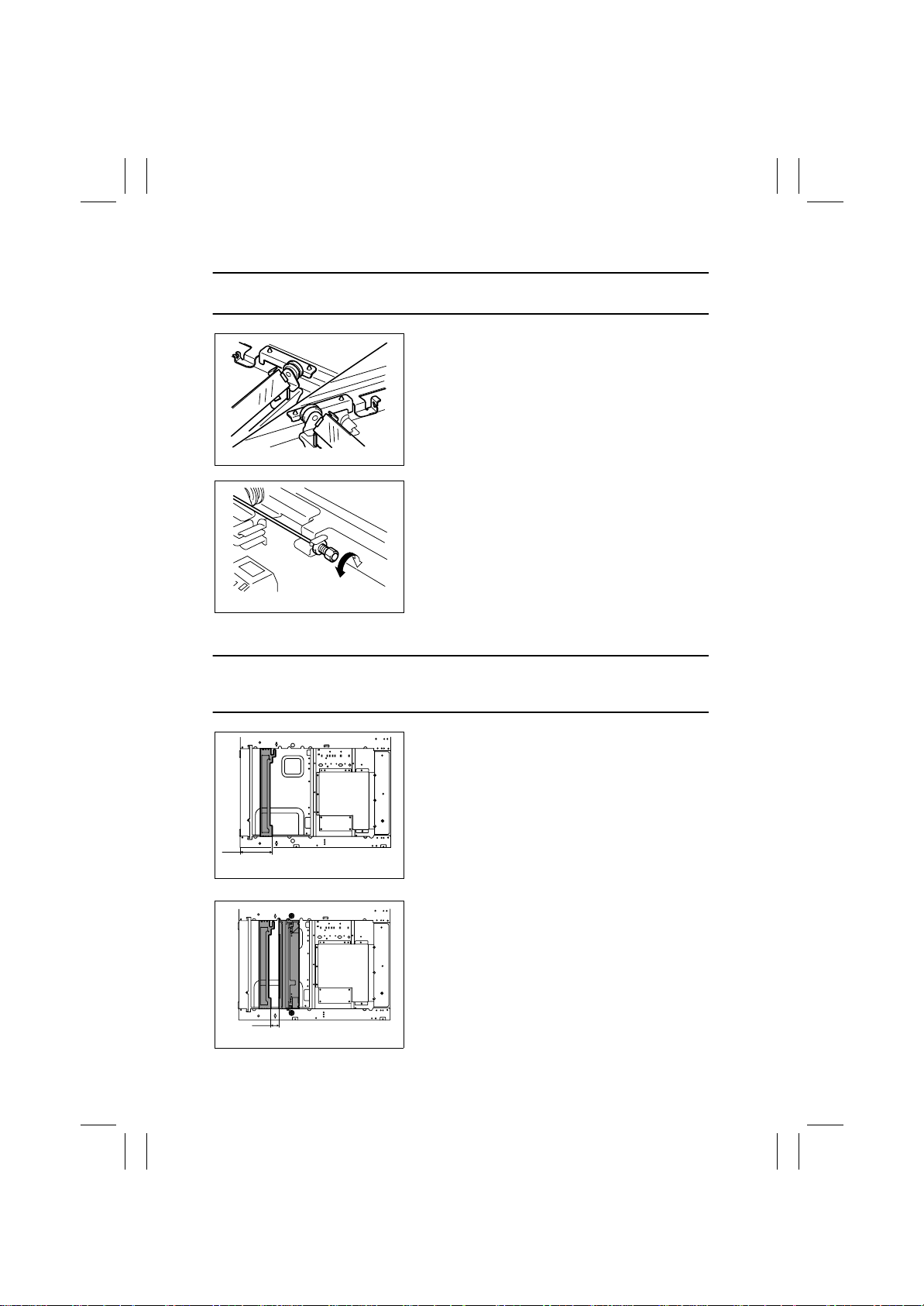
(2) Focus Positioning of the Scanner and 2nd/3rd Mirrors Carriage
This adjustment must be made in the following case:
• The Scanner Drive Cables have been rewound
.
1. Slide the 2nd/3rd Mirrors Carriage to the center
until it is pressed up against the cutouts in the
rails.
4025D122AA
2. Turn the cable length adjusting screw so that the
2nd/3rd Mirrors Carriage contacts the cutouts in
the rails.
4025D123AA
(3) Scanner Position Adjustment
This adjustment must be made in the following case:
• The Scanner Drive Cables have been rewound.
• Focus Positioning of the Scanner and 2nd/3rd Mirrors Carriage must be completed.
1. Slide the 2nd/3rd Mirrors Carriage to the position
shown on the left.
120 mm
4025D124AB
2. Secure the Scanner in the position shown on the
left using Scanner positioning Screws.
☞
D-20
3. Make the FD-Mag. adjustment.
☞
D-68
30 mm
4025D125AB
D-44
Page 47

FrameMaker Ver.5.5E(PC) 8020/8031 DIS/REASSEMBLY, ADJUSTMENT
02.08.19
3-4. ELECTRICAL/IMAGE ADJUSTMENT
(1) Accessing the Tech. Rep. Mode
1. Press the Utility key.
2. Touch [Meter Count].
3. Press the following keys in this order:
Stop → 0 → 0 → Stop → 0 → 1
NOTE
• Ensure appropriate security for Tech. Rep. mode setting procedures. They should never
be known to any unauthorized person not involved with service jobs.
(2) Producing a Test Print
1. Call the Tech. Rep . Mode to the screen.
2. Touch [Test Print].
3. Select the desired test pattern type.
4. Make the necessar y settings.
5. Press the Start key.
D-45
Page 48
FrameMaker Ver.5.5E(PC) 8020/8031 DIS/REASSEMBLY, ADJUSTMENT
02.08.19
✽
Printer
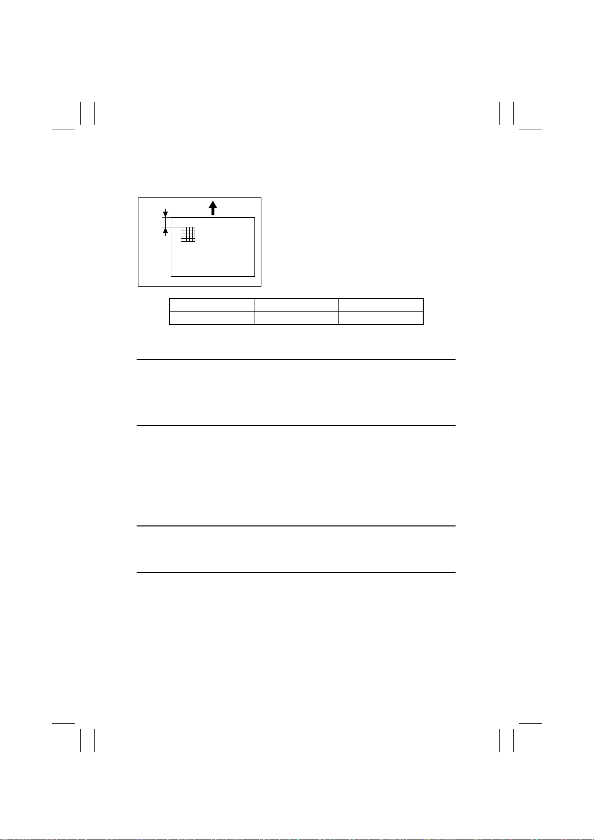
(3) Top Margin
Requirement
Width A on the test pattern produced should fall
Width
A
4004D511AA
Specifications Adjustment Mode Setting Range
5.0 or 7.0 ± 1.0 mm Top Margin -2.0 mm to +2.0 mm
✽
The leading edge erase width is set to 5 mm or 7 mm by “ Erase” under “Administrator
Mode.”
This adjustment must be made in the following case:
• The LPH Unit has been replaced.
• The paper type has been changed.
• The image on the copy deviates in the FD direction.
• A faint image occurs on the leading edge of the image.
• A misfeed occurs at the 2nd image transfer section.
within the following range.
Adjustment Procedure
1. Load the 1st Drawer with A3 plain paper.
2. Select plain paper on the Paper Type Setting Dial.
3. Select the 1st Drawer .
4. Call the Tech. Rep . Mode to the screen.
5. Touch these keys in this order: “Machine Adjust” → “PRT Area” → “Top Margin.”
6. Press the Start key to let the copier produce a test pattern.
7. Check the dimension of width A on the test pattern.
8. If width A falls outside the specified range, change the setting using the Up/Down key.
• If width A is longer than the specifications, make the setting value smaller than the cur-
rent one.
• If width A is shorter than the specifications, make the setting value greater than the cur-
rent one.
9. Press the Start key to let the copier produce a test pattern.
10. Check the dimension of width A on the test pattern.
11. If width A is outside the specified range, change the setting again and make a check
again.
12. If width A falls within the specified range, touch “END.”
13. Following the same procedure, adjust for thick paper and OHP.
14. Go back to the initial Tech. Rep. Mode screen.
15. Touch “Test Print.”
16. Select “Halftone Pattern.”
D-46
Page 49

FrameMaker Ver.5.5E(PC) 8020/8031 DIS/REASSEMBLY, ADJUSTMENT
02.08.19
17. Select “Cyan,” “SINGLE,” and “HYPER.”
18. Press the Clear key to clear the density setting.
19. Enter “255” from the 10-Key Pad.
20. Press the Start key to let the copier produce a test pattern.
21. Check to see if the image on the leading and trailing edges of the test pattern is faint.
✽
If the image is faint:
22. Touch these keys in this order: “Machine Adjust” → “PRT Area” → “Top Margin.”
23. Touch “2nd Transfer Timing” and then use the Down key to decrease the setting.
NOTE
• Decreasing the setting makes transfer timing faster. An abnormally low setting could,
however, result in a paper misfeed.
24. Touch “END.”
25. Produce a halftone test pattern again.
26. Check the image on the leading and trailing edges of the test pattern.
27. If the image on the leading and trailing edges of the test pattern is faint, change the setting and make a check again.
D-47
Page 50
FrameMaker Ver.5.5E(PC) 8020/8031 DIS/REASSEMBLY, ADJUSTMENT
02.08.19
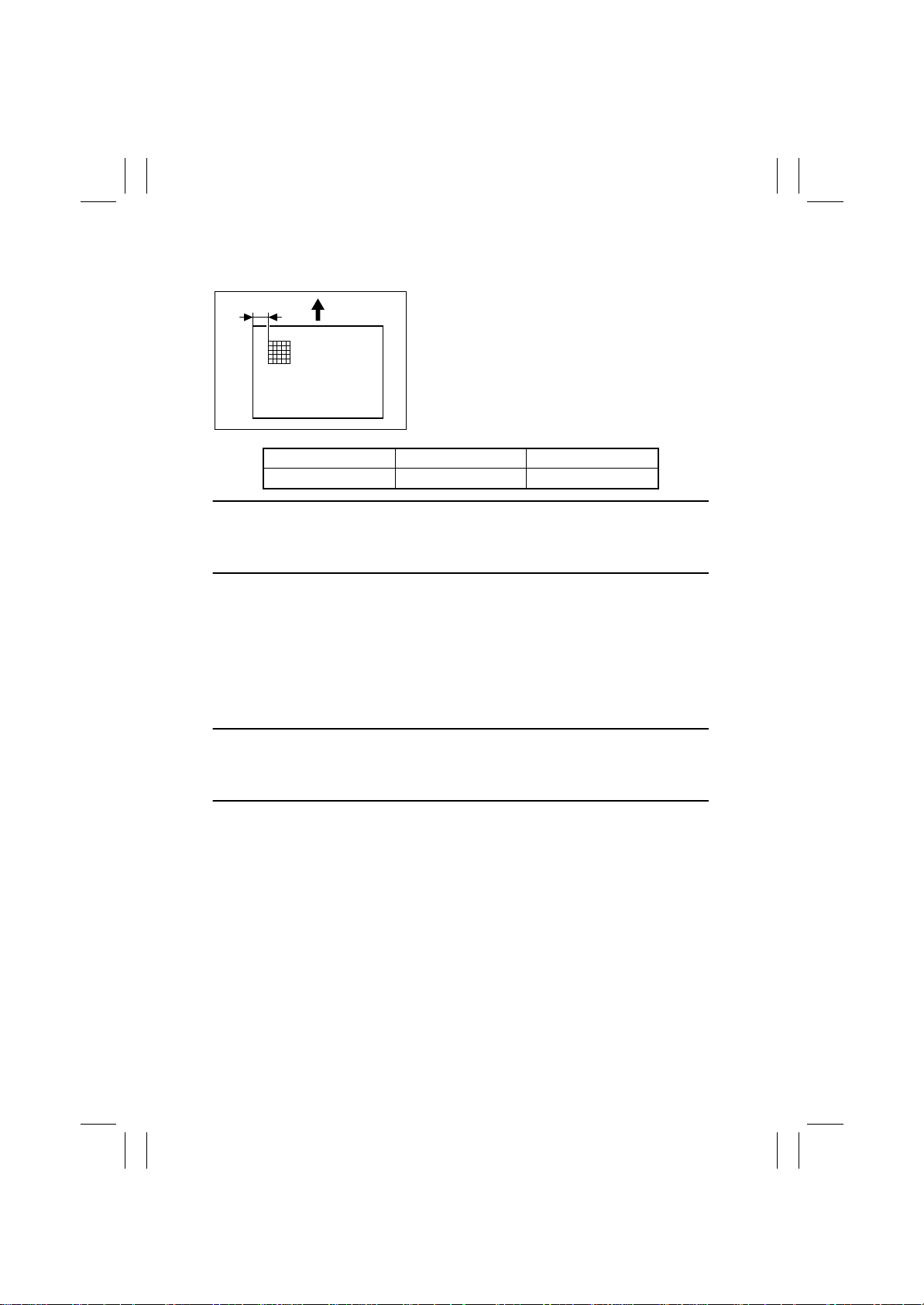
(4) Left Margin
Requirement
Width A
4004D512AA
Specifications Adjustment Mode Setting Range
3.0 ± 1.0 mm Left Margin -3.0 mm to +3.0 mm
This adjustment must be made in the following case:
• The LPH Unit has been replaced.
• A paper feed unit has been added.
• The image on the copy deviates in the CD direction.
Adjustment Procedure
1. Load the 1st Drawer with A3 plain paper.
2. Select plain paper on the Paper Type Setting Dial.
3. Select the 1st Drawer .
4. Call the Tech. Rep . Mode to the screen.
5. Touch these keys in this order: “Machine Adjust” → “PRT Area” → “Left Margin.”
6. Press the Start key to let the copier produce a test pattern.
7. Check the dimension of width A on the test pattern.
8. If width A falls outside the specified range, change the setting using the Up/Down key.
Width A on the test pattern produced should fall
within the following range.
• If width A is longer than the specifications, make the setting value smaller than the cur-
rent one.
• If width A is shorter than the specifications, make the setting value greater than the cur-
rent one.
9. Press the Start key to let the copier produce a test pattern.
10. Check the dimension of width A on the test pattern.
11. If width A is outside the specified range, change the setting again and make a check
again.
12. If width A falls within the specified range, touch “END.”
13. Following the same procedure, adjust for all other paper sources. (Use A4 plain paper
for the Manual Bypass Tray.)
D-48
Page 51
FrameMaker Ver.5.5E(PC) 8020/8031 DIS/REASSEMBLY, ADJUSTMENT
02.08.19
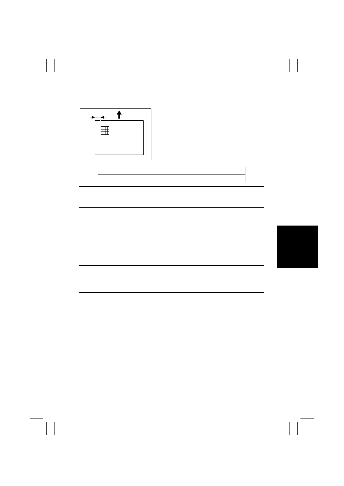
(5) Dup. Left Margin
Requirement
Width A
4004D512AA
Specifications Adjustment Mode Setting Range
3.0 ± 1.0 mm Dup. Left Margin -3.0 mm to +3.0 mm
This adjustment must be made in the following case:
• The Duplex Unit has been set up.
• The image on the backside of the 2-sided copy deviates in the CD direction.
Adjustment Procedure
1. Load the 1st Drawer with A3 plain paper.
2. Select plain paper on the Paper Type Setting Dial.
3. Select the 1st Drawer .
4. Call the Tech. Rep . Mode to the screen.
5. Touch these keys in this order: “Machine Adjust” → “PRT Area” → “Dup. Left Margin.”
6. Press the Start key to let the copier produce a test pattern.
7. Check the dimension of width A on the test pattern.
8. If width A falls outside the specified range, change the setting using the Up/Down key.
Width A on the test pattern produced should fall
within the following range.
• If width A is longer than the specifications, make the setting value smaller than the cur-
rent one.
• If width A is shorter than the specifications, make the setting value greater than the cur-
rent one.
9. Press the Start key to let the copier produce a test pattern.
10. Check the dimension of width A on the test pattern.
11. If width A is outside the specified range, change the setting again and make a check
again.
12. If width A falls within the specified range, touch “END.”
13. Following the same procedure, adjust for all other paper sources.
D-49
Page 52
FrameMaker Ver.5.5E(PC) 8020/8031 DIS/REASSEMBLY, ADJUSTMENT
02.08.19
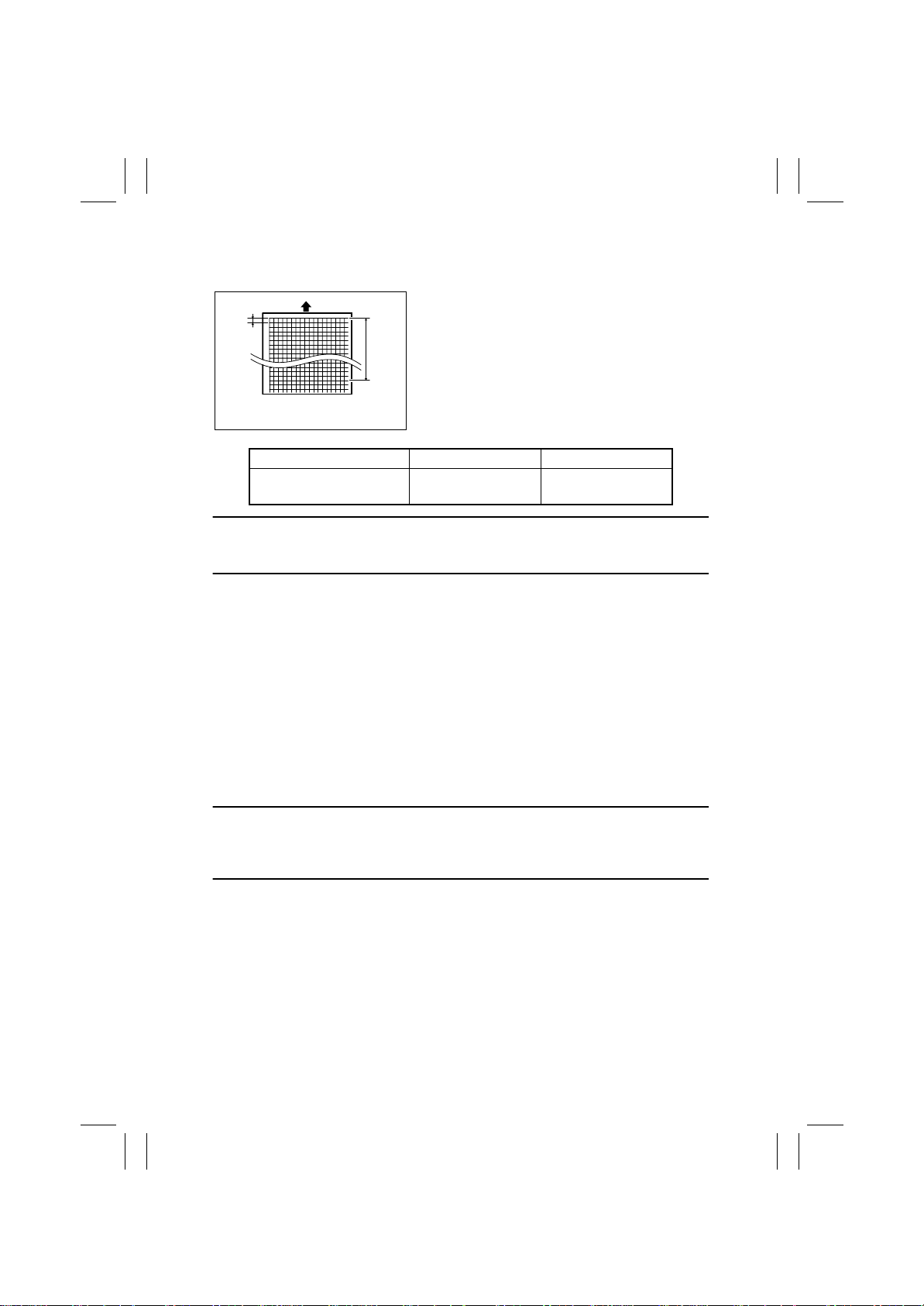
(6) Zoom for FD
Requirement
Width A and width B on the test pattern produced
Width
A
4025D126AD
Specifications Adjustment Mode Setting Range
Width A: 7.9 to 8.3 mm
Width B: 389.1 to 392.1 mm
This adjustment must be made in the following case:
• The CD-Mag. or FD-Mag. adjustment becomes necessary.
• The image on the copy distorts (stretched, shrunk).
Adjustment Procedure
1. Load the 1st Drawer with A3 plain paper.
2. Select plain paper on the Paper Type Setting Dial.
3. Select the 1st Drawer .
4. Call the Tech. Rep . Mode to the screen.
5. Touch these keys in this order: “Test Print” → “Lattice Pattern.”
6. Select “Black,” “SINGLE,” “FEET,” “SINGLE,” “CD Width:2,” “FD Width:2,” “Density:255,” and “Normal.”
7. Press the Start key to let the copier produce a test pattern.
8. Check width A (equivalent to one grid) and width B (equivalent to 48 gr ids) on the test
pattern.
9. Touch these keys in this order: “Machine Adjust” → “PRT Area” → “Zoom for FD.”
10. If width A or width B falls outside the specified range, Change the setting value using
the 10-Key Pad.
should fall within the following ranges.
Width A : equivalent to one grid
Width
Width B : equivalent to 48 grids
B
Zoom for FD
-10 to +10
(0.2 mm/step)
• If width A or B is longer than the specifications, make the setting value smaller than the
current one.
• If width A or B is shorter than the specifications, make the setting value greater than the
current one.
11. Press the Start key to let the copier produce a test pattern.
12. Check width A and width B on the test pattern.
13. If width A or B falls outside the specified range, change the setting value and make a
check again.
14. If width A or B falls within the specified range, touch “END.”
15. Following the same procedure, adjust for “T hick 1,” “Thick 2,” “Thick 3,” “OHP,” and
“Envelope.” (Check width A only for “OHP” and “Envelope.”)
D-50
Page 53
FrameMaker Ver.5.5E(PC) 8020/8031 DIS/REASSEMBLY, ADJUSTMENT
02.08.19
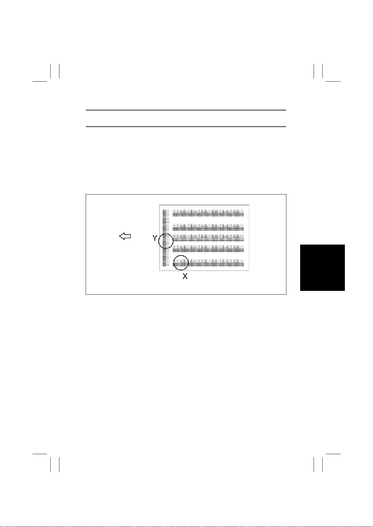
(7) Color Shift Correction
This adjustment must be made in the following case:
• Color shift occurs.
Adjustment Procedure
1. Call the Tech. Rep . Mode to the screen.
2. Touch these keys in this order: “Machine Adjust” → “Color Shift Correction.”
3. Select “Cyan,” and “SINGLE.”
4. Press the Start key to let the copier produce a test pattern.
5. Check to see if the black cross at the location shown below deviates or not.
6. If it deviates, change the setting using the Up/Down key.
Setting Instructions
D-51
C4025o276AA
Page 54
FrameMaker Ver.5.5E(PC) 8020/8031 DIS/REASSEMBLY, ADJUSTMENT
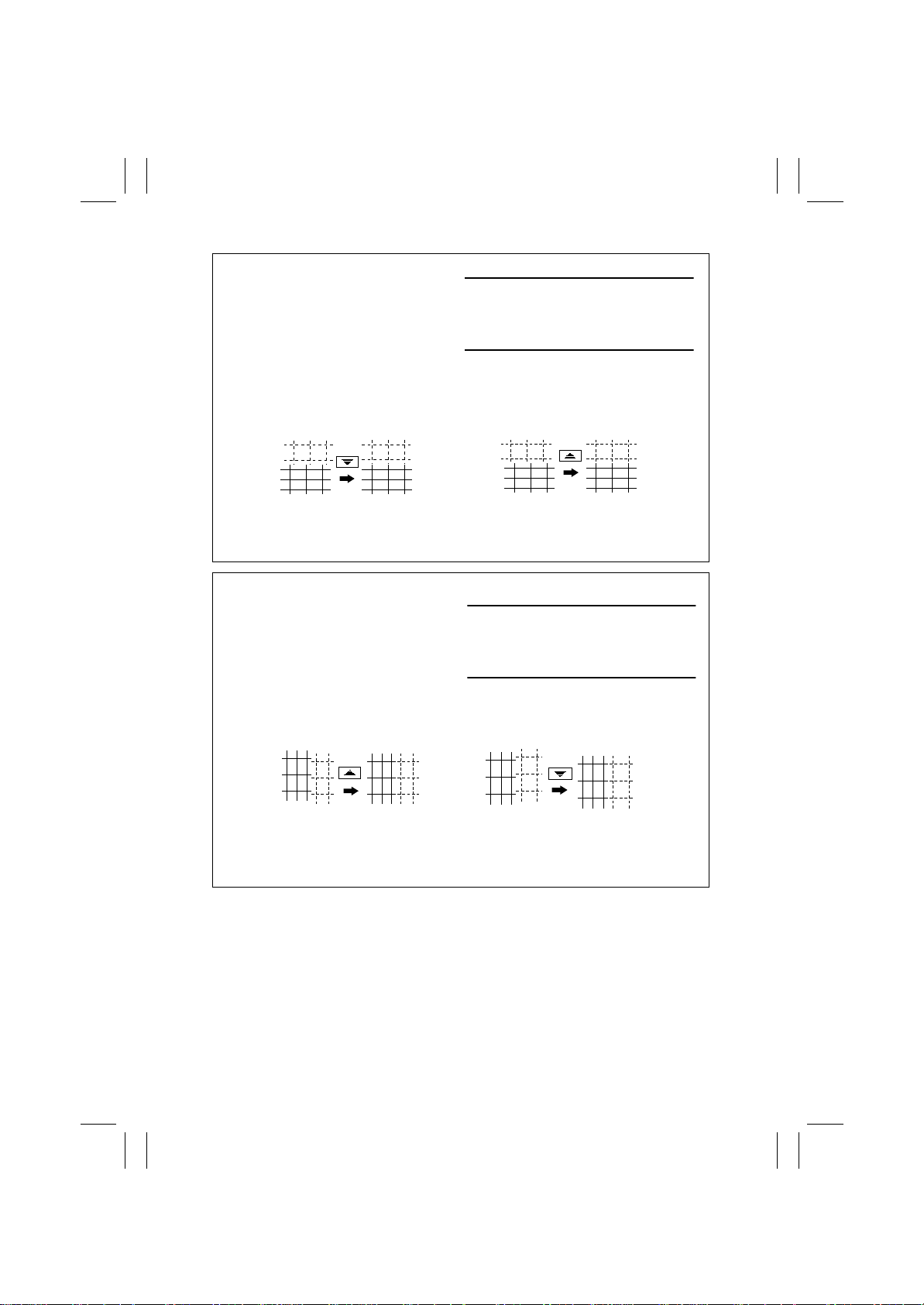
02.08.19
Adjustment for X direction: Check point X
• If the cross deviates in the direction of
C, decrease the setting.
• If the cross deviates in the direction of
D, increase the setting.
Direction of C
C4025s313AA C4025s314AA
Adjustment for Y direction: Check point Y
Direction of C Direction of D
C4025s315AB
Direction of D
• If the cross deviates in the direction of
C, increase the setting.
• If the cross deviates in the direction of
D , decrease the setting.
C4025s316AB
D-52
Page 55
FrameMaker Ver.5.5E(PC) 8020/8031 DIS/REASSEMBLY, ADJUSTMENT
02.08.19
(8) Leading Edge Tilt Adjustment
This adjustment must be made in the following case:
• Leading edge tilt occurs.
• The LPH Assy Bk has been replaced.
Adjustment Procedure
1. Call the Tech. Rep . Mode to the screen.
2. Touch these keys in this order: “Machine Adjust” → “Color Shift Correction.”
3. Select “SINGLE.”
4. Press the Start key to let the copier produce a test pattern.
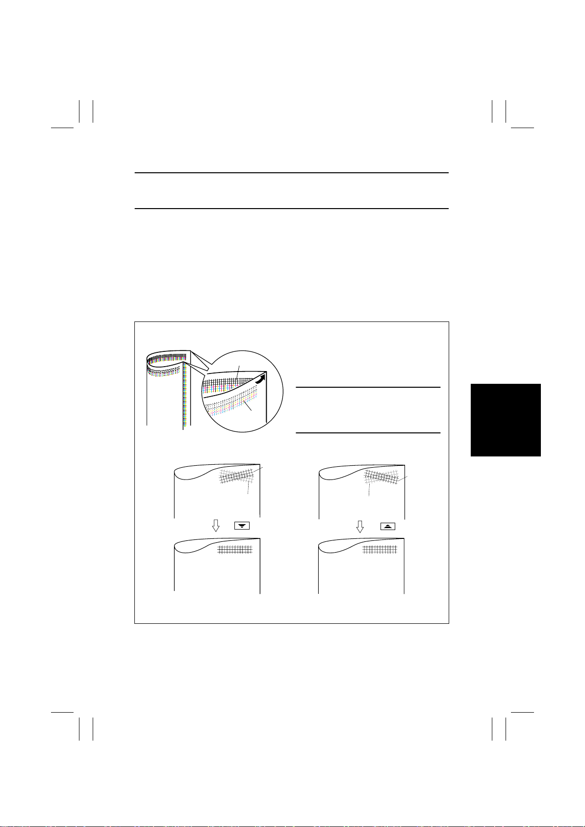
5. Fold the test pattern in half lengthwise.
6. Check black lines A and B for devi ation.
7. Touch the “Black” key and change the setting using the Up/Down key.
Setting Instructions
Check point A,B
A
• If the lines deviate in the C direction,
decrease the setting.
B
C4025o310AA
Direction of C Direction of D
• If the lines deviate in the D direction,
increase the setting.
A
B
C4025o311AA C4025o312AA
B
A
D-53
Page 56
FrameMaker Ver.5.5E(PC) 8020/8031 DIS/REASSEMBLY, ADJUSTMENT
02.08.19
(9) LPH Chip Adjust
This adjustment must be made in the following case:
• White lines or black lines in FD occur
• The LPH Assy has been replaced.
• The LPH Unit has been replaced.
Adjustment Procedure
1. Call the Tech. Rep . Mode to the screen.
2. Touch these keys in this order: “Test Print” → “LPH Pattern.”
3. Select “SINGLE,” “HYPER,” “Gradation,” and “Border Line: ON.”
4. Press the Start key to let the copier produce a test pattern.
5. Check the test pattern for the location, at which white lines or black lines in FD occur.
6. Touch these keys in this order: “Machine Adjust” → “LPH Chip Adjust.”
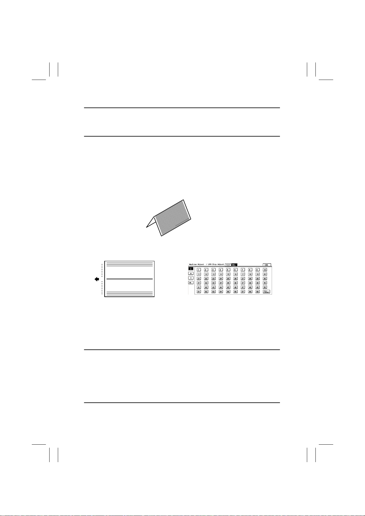
7. Fold the test pattern in half (with the pattern face on the outside).
4025D127AA
8. The chip boundary line on the crease (the center) of the test pattern corresponds to
“30” on the panel.
1
30
59
4025D128AB 4025D503CA
9. Find the number on the panel, to which the location of white lines or black lines in FD
checked in step 5 corresponds.
10. Select the color (C, M, Y, or Bk) in which white lines or black lines in FD occur.
✽
If the lines occur only in green on the test pattern, select Y.
11. Touch the corresponding number on the panel. (It is then highlighted and the setting
value is displayed besides the highlighted number.)
12. Change the setting value using the 10-Key Pad.
Black lines in FD: Decrease the setting value.
White lines in FD: Increase the setting value.
✽
When a new LPH Unit has been installed, corrections can be made for up to eight locations.
✽
Corrections for up to five locations can be made through factory adjustments. If white
lines or black lines in FD occur, therefore, corrections can therefore be made in the field
for three to eight locations.
✽
If lines persist even after the correction procedures, change the LPH Unit.
13. Select HYPER and color.
14. Press the Start key to let the copier produce a test pattern and check for lines.
D-54
Page 57

FrameMaker Ver.5.5E(PC) 8020/8031 DIS/REASSEMBLY, ADJUSTMENT
02.08.19
(10) Gradation Adjust
This adjustment must be made in the following case:
• Color reproduction performance becomes poor.
• The IU has been replaced.
• The Image Transfer Belt Unit has been replaced.
Adjustment Procedure
1. Call the Tech. Rep . Mode to the screen.
2. Touch “Gradation Adjust.”
3. Press the Start key to let the copier produce a test pattern.
4. Place the test pattern produc ed on the Original Glass.
5. Place ten blank sheets of A3 paper on the test pattern and then lower the Original
Cover.
6. Press the Start key (to let the copier start scanning the original).
7. Repeat steps from 2 to 6 twice (a total of three cycles).
8. The Adj. Value and Conv . Value will be displayed for Max and Highlight of each color (C,
M, Y, Bk).
9. Check the Conv. Value ac cording to the following procedure.
• Max 0 ± 100 and Highlight 0 ± 60: It completes the adjustment procedure.
• If neither Max nor Highlight falls outside the ranges specified above: Perform steps from
2 to 6.
✽
If a fault is detected, “0” is displayed for all values . In this case, turn OFF and ON the
Power Switch and perform Gradation Adjust once again.
✽
If neither Max nor Highlight still remains outside the specified ranges, perform PRT Max
Density or PRT Highlight.
D-55
Page 58

FrameMaker Ver.5.5E(PC) 8020/8031 DIS/REASSEMBLY, ADJUSTMENT
02.08.19
(11) PRT Max Density
This adjustment must be made in the following case:
• An image quality problem is not corrected even after Gradation Adjust has been run.
Adjustment Procedure
1. Call the Tech. Rep . Mode to the screen.
2. Touch these keys in this order: “Image Adjust” → “PRT Max Density.”
3. Select the color to be adjusted.
4. Enter the new setting from the 10-Key Pad.
• To increase the maximum amount of toner sticking, increase the setting value.
• To decrease the maximum amount of toner sticking, decrease the setting value.
5. Touch “END” to return to the “Image Adjust” menu screen.
6. Touch “Stabilizer.”
7. Touch “Stabilizer Mode.”
8. Press the Start key to validate the adjustment value.
9. Check the copy image for any image problem.
D-56
Page 59

FrameMaker Ver.5.5E(PC) 8020/8031 DIS/REASSEMBLY, ADJUSTMENT
02.08.19
(12) PRT Highlight
This adjustment must be made in the following case:
• An image quality problem is not corrected even after Gradation Adjust has been run.
Adjustment Procedure
1. Call the Tech. Rep . Mode to the screen.
2. Touch these keys in this order: “Image Adjust” → “PRT Highlight.”
3. Select the color to be adjusted.
4. Enter the new setting from the 10-Key Pad.
• To make the Highlight portion darker, increase the setting value.
• To make the Highlight portion lighter, decrease the setting value.
5. Touch “END” to return to the “Image Adjust” menu screen.
6. Touch “Stabilizer.”
7. Touch “Stabilizer Mode.”
8. Press the Start key to validate the adjustment value.
9. Check the copy image for any image problem.
D-57
Page 60

FrameMaker Ver.5.5E(PC) 8020/8031 DIS/REASSEMBLY, ADJUSTMENT
02.08.19
(13) Background Voltage Margin
This adjustment must be made in the following case:
• Foggy background occurs.
Adjustment Procedure
1. Call the Tech. Rep . Mode to the screen.
2. Touch these keys in this order: “Image Adjust” → “PRT Highlight.”
3. Select the color to be adjusted.
4. Enter the new setting from the 10-Key Pad.
• To make the background level foggier, increase the setting value.
• To make the background level less foggy, decrease the setting value.
5. Touch “END” to return to the “Image Adjust” menu screen.
6. Touch “Stabilizer.”
7. Touch “Stabilizer Mode.”
8. Press the Start key to validate the adjustment value.
9. Check the copy image for any image problem.
D-58
Page 61

FrameMaker Ver.5.5E(PC) 8020/8031 DIS/REASSEMBLY, ADJUSTMENT
02.08.19
(14) ATDC Level Setting
This adjustment must be made in the following case:
• T/C is changed as a result of changes in environmental conditions.
Adjustment Procedure
1. Call the Tech. Rep . Mode to the screen.
2. Touch these keys in this order: “Image Adjust” → “ATDC Level Setting.”
3. Select the color to be adjusted.
4. Enter the new setting from the 10-Key Pad.
• To increase T/C, increase the setting value.
• To decrease T/C, decrease the setting value.
5. Touch “END” to validate the adjustment value.
6. Check the copy image for any image problem.
D-59
Page 62

FrameMaker Ver.5.5E(PC) 8020/8031 DIS/REASSEMBLY, ADJUSTMENT
02.08.19
(15) AE Adjust
This adjustment must be made in the following case:
• Foggy background occurs in the Auto Exposure mode.
Adjustment Procedure
1. Call the Tech. Rep . Mode to the screen.
2. Touch these keys in this order: “Image Adjust” → “AE Adjust.”
3. Enter the new setting from the 10-Key Pad.
• To make the background level foggier, change the setting value to 3 or 4.
• To make the background level less foggy, change the setting value to 0 or 1.
4. Touch “END” to validate the adjustment value.
5. Check the copy image for any image problem.
D-60
Page 63

FrameMaker Ver.5.5E(PC) 8020/8031 DIS/REASSEMBLY, ADJUSTMENT
02.08.19
(16) 2nd Transfer Adjust
This adjustment must be made in the following case:
• A transfer fail ure occ urs at the trailing edge (only with plain paper).
Adjustment Procedure
1. Call the Tech. Rep . Mode to the screen.
2. Touch these keys in this order: “Image Adjust” → “2nd Transfer Adjust.”
3. Select the side of the image (First side or Second side), on which the transfer failure at
the trailing edge occurs.
4. Enter the new setting from the 10-Key Pad.
• To increase the ATVC value (in the direction of a foggier image), decrease the setting
value.
• To decrease the ATVC value (in the direction of a less foggy image), increase the setting
value.
5. Touch “END” to validate the adjustment value.
6. Check the copy image for any image problem.
D-61
Page 64

FrameMaker Ver.5.5E(PC) 8020/8031 DIS/REASSEMBLY, ADJUSTMENT
02.08.19
(17) Fuser Temp.
This adjustment must be made in the following case:
• Fusing performance is poor or offset occurs when the paper type or environmental condi-
tions are changed.
Adjustment Procedure
1. Call the Tech. Rep . Mode to the screen.
2. Touch these keys in this order: “Machine Adjust” → “Fuser Temp.”
3. Select the paper type and Fusing Roller type.
4. Enter the new setting from the 10-Key Pad.
If fusing performance is poor, increase the setting.
✽ The temperature does not change immediately when the setting is change. Wait a while
before performing the subsequent steps.
5. Touch “END” to validate the adjustment value.
6. Check the copy image for any image problem.
D-62
Page 65
FrameMaker Ver.5.5E(PC) 8020/8031 DIS/REASSEMBLY, ADJUSTMENT
02.08.19
(18) Fuser Speed
This adjustment must be made in the following case:
• Brush effect or blurred image is ev ident as a result of changes in environmental condi-
tions or degraded durability.
Adjustment Procedure
1. Call the Tech. Rep . Mode to the screen.
2. Touch these keys in this order: “Machine Adjust” → “Fuser Speed.”
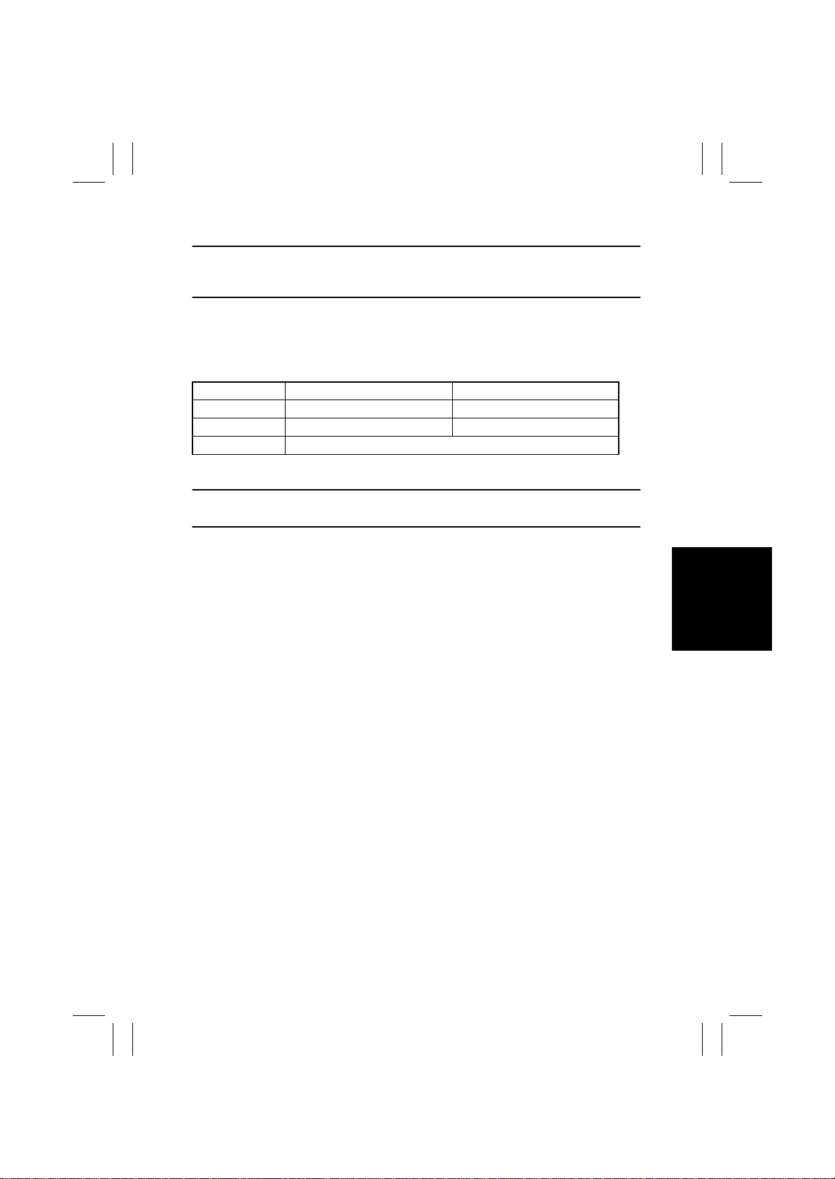
3. Select the transpor t speed, at which the brush effect or blurred image has occurred.
Transport Speed 8031 8020
135 mm/s Plain paper: monochrome, color Plain paper: monochrome
90 mm/s — Plain paper: color
60 mm/s Thick paper, OHP, envelope, postcard, labels: monochrome, color
4. Enter the new setting from the 10-Key Pad.
• If brush effect is evident, decrease the setting.
• If a blurred image occurs, increase the setting.
5. Touch “END” to validate the adjustment value.
6. Check the copy image for any image problem.
D-63
Page 66
FrameMaker Ver.5.5E(PC) 8020/8031 DIS/REASSEMBLY, ADJUSTMENT
02.08.19
✽
IR
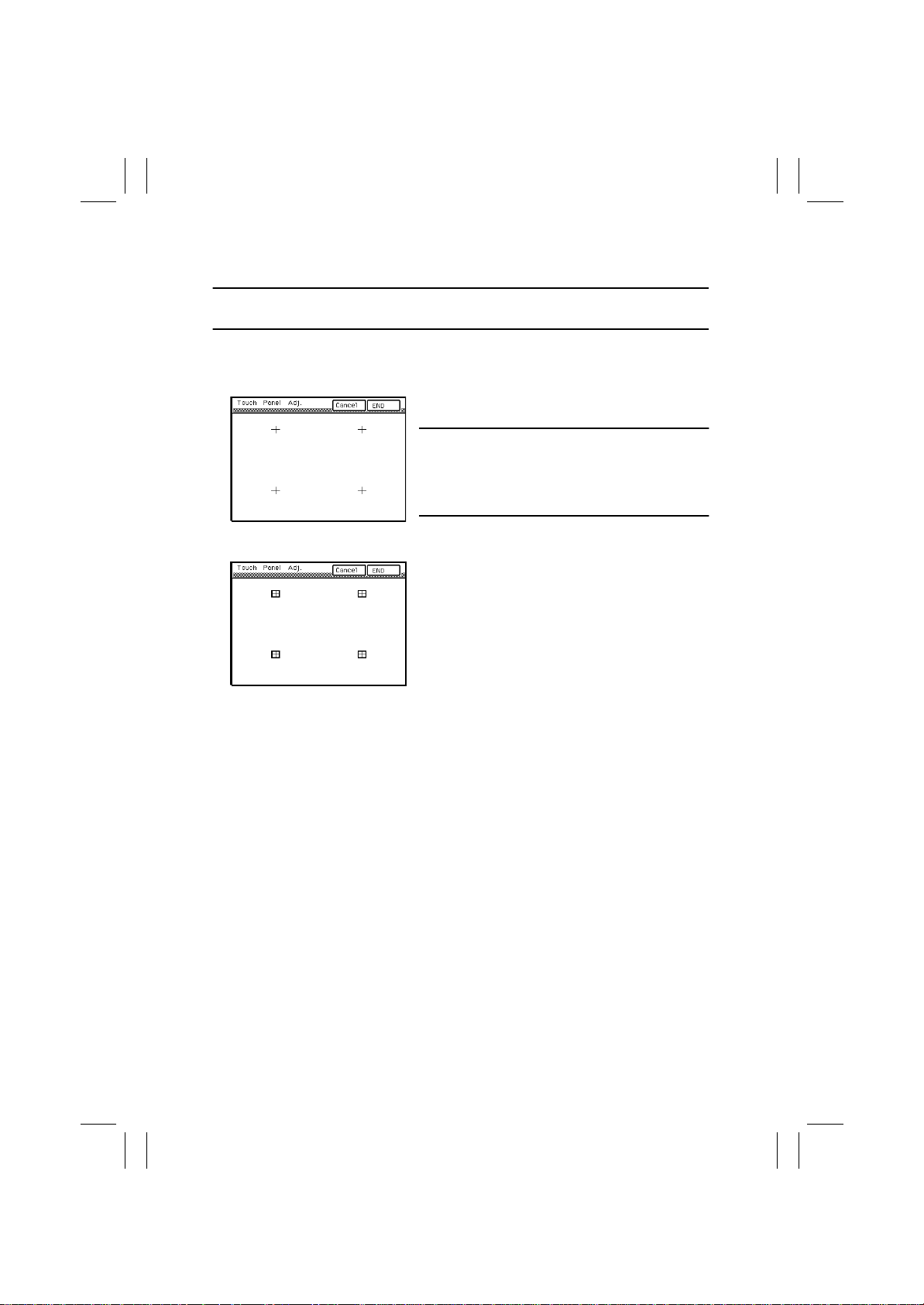
(19) Touch Panel Adj.
NOTE
• Make this adjustment if the Touc h Panel is slow to respond to a pressing action.
1. Press the following keys:
Stop → 0 → Stop → 3
2. Using the tip of a pen or similar object, touch the
four crosses (+) on the screen in sequence.
NOTES
• These crosses may be touched in any order; but
be sure to touch the center of each cross.
• Use care not to damage the screen surface with
the tip of the pen.
1155D191CA
3. The cross touched changes into a grid marker
that consists of a square with a cross superimposed.
4. Touch [END].
1155D192CA
D-64
Page 67
FrameMaker Ver.5.5E(PC) 8020/8031 DIS/REASSEMBLY, ADJUSTMENT
02.08.19
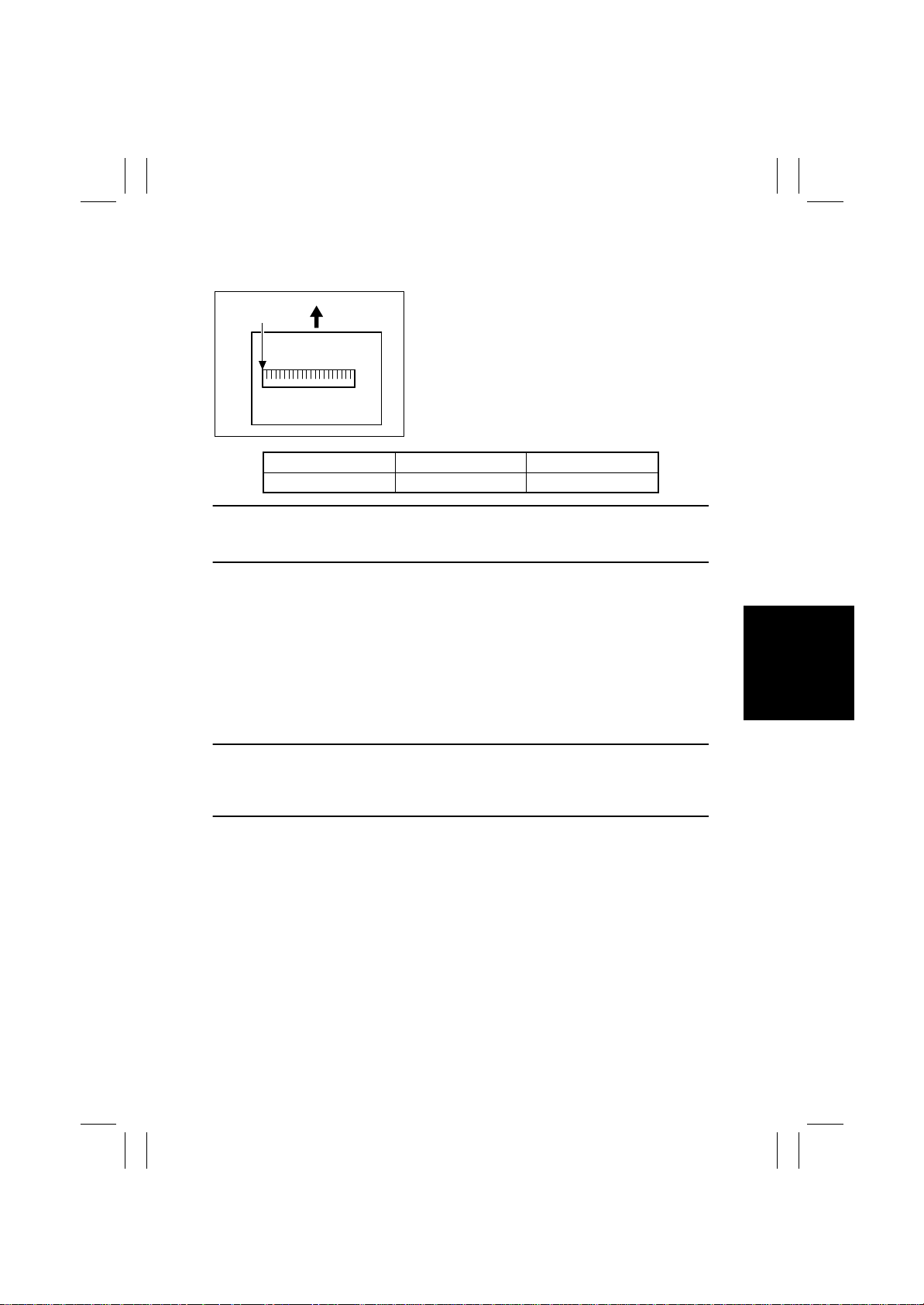
(20) Left Image
Requirement
Scale 0-mm
Position
4004D514AA
Specifications Adjustment Mode Setting Range
0 ± 1.0 mm Left Image - 10.0 to +10.0
This adjustment must be made in any of the following cases:
• The Original Glass has been replaced.
• The Scanner Home Sensor has been replaced.
Adjustment Procedure
1. Call the Tech. Rep . Mode to the screen.
2. Touch these keys in this order: “Machine Adjust” → “IR Area.”
3. Touch “Left Image.”
4. Place a scale on the Original Glass so that it runs parallel with the Original Width Scale
and its leading edge is aligned with the Original Length Scale.
5. Press the Start key to make a copy.
6. Check the image on the copy produced.
7. If the image does not meet the specifications, change the setting using the Up/Down
key.
• The position of 0 mm of the scale on the sample
copy produced should fall within the following
range.
• The adjustment of Left Margin on the printer side
must have been made to meet the specifications.
☞
D-48
• If the 0-mm position on the sample copy is on the right side of the correct 0-mm position
perpendicularly to the feeding direction (less than -1 mm), decrease the setting.
• If the 0-mm position on the sample copy is on the left side of the correct 0-mm position
perpendicularly to the feeding direction (exceeding 1 mm), increase the setting.
8. Press the Start key to make a copy.
9. Check the image on the copy to see if the specifications are met.
10. If it fails to meet the specifications, change the setting and make a check again.
11. If it meets the specifications, touch “END.”
D-65
Page 68
FrameMaker Ver.5.5E(PC) 8020/8031 DIS/REASSEMBLY, ADJUSTMENT
02.08.19
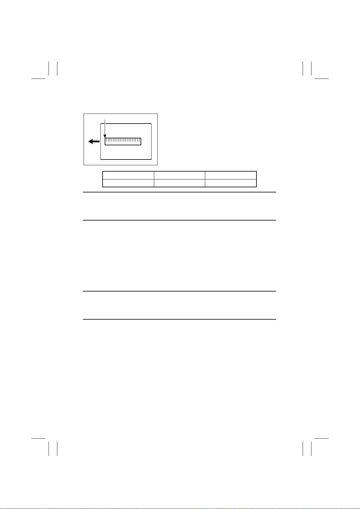
(21) Top Image
Requirement
Scale 10-mm Position
4004D515AA
Specifications Adjustment Mode Setting Range
10.0 ± 1.0 mm Top Image -5.0 to +5.0
This adjustment must be made in any of the following cases:
• The CCD Unit has been replaced.
• The Original Glass has been replaced.
• The Original Scale has been replaced.
Adjustment Procedure
• The position of 10 mm of the scale on the sample
copy produced should fall within the following
range.
• The adjustment of Top Margin on the printer side
must have been made to meet the specifications.
☞
D-46
1. Call the Tech. Rep . Mode to the screen.
2. Touch these keys in this order: “Machine Adjust” → “IR Area.”
3. Touch “Top Image.”
4. Place a scale on the Original Glass so that it runs parallel with the Original Length
Scale and its leading edge is aligned with the Original Width Scale.
5. Press the Start key to make a copy.
6. Check the image on the copy produced.
7. If the image does not meet the specifications, change the setting using the Up/Down
key.
• If the 10-mm position on the sample copy is on the right side of the c orrect 10-mm posi-
tion parallel to the feeding direction (less than 9 mm), decrease the setting.
• If the 10-mm position on the sample copy is on the left side of the correct 10-mm position
parallel to the feeding direction (exceeding 11 mm), increase the setting.
8. Press the Start key to make a copy.
9. Check the image on the copy to see if the specifications are met.
10. If it fails to meet the specifications, change the setting and make a check again.
11. If it meets the specifications, touch “END.”
D-66
Page 69
FrameMaker Ver.5.5E(PC) 8020/8031 DIS/REASSEMBLY, ADJUSTMENT
02.08.19
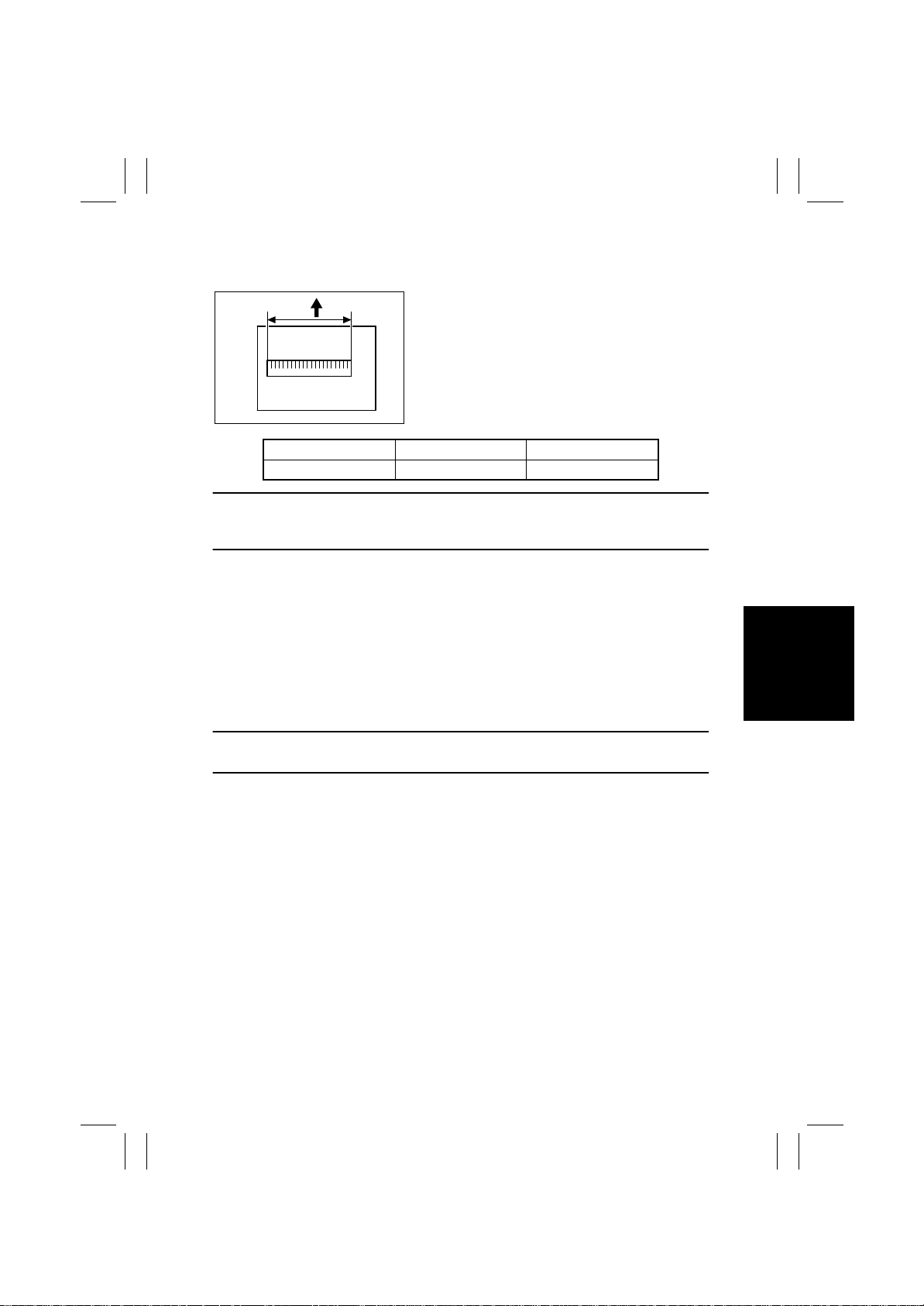
(22) CD-Mag.
Requirement
200 mm
4004D516AB
Specifications Adjustment Mode Setting Range
200 ± 1.0 mm CD-Mag. 0.990 to 1.010
This adjustment must be made in any of the following cases:
• The CCD Unit has been replaced.
• The lens has been replaced.
Adjustment Procedure
1. Call the Tech. Rep . Mode to the screen.
2. Touch these keys in this order: “Machine Adjust” → “IR Area.”
3. Touch “CD-Mag.”
4. Place a scale on the Original Glass so that it runs parallel with the Original Width Scale
and its leading edge is aligned with the Original Length Scale.
5. Press the Start key to make a copy.
6. Check the image on the copy produced.
7. If the image does not meet the specifications, change the setting using the Up/Down
key.
• The 200-mm width of the scale on the sample cop y
produced should fall within the following range.
• The adjustment of Zoom for FD on the printer side
must have been made to meet the specifications.
☞
D-50
• If the specified width on the copy is less than 199 mm, increase the setting.
• If the specified width on the copy exceeds 201 mm, decrease the setting.
8. Press the Start key to make a copy.
9. Check the image on the copy to see if the specifications are met.
10. If it fails to meet the specifications, change the setting and make a check again.
11. If it meets the specifications, touch “END.”
D-67
Page 70
FrameMaker Ver.5.5E(PC) 8020/8031 DIS/REASSEMBLY, ADJUSTMENT
02.08.19
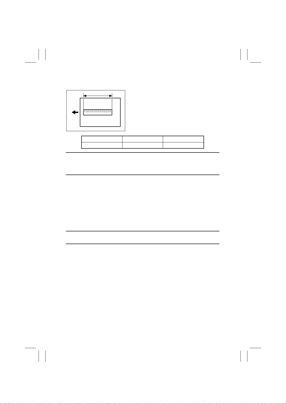
(23) FD-Mag.
Requirement
300 mm
4004D517AB
Specifications Adjustment Mode Setting Range
300 ± 1.5 mm FD-Mag. 0.990 to 1.010
This adjustment must be made in any of the following cases:
• The Scanner Assy has been replaced.
• The Scanner Motor has been replaced.
• The Scanner Drive Cables have been replaced.
Adjustment Procedure
• The 300-mm width of the scale on the sample cop y
produced should fall within the following range.
• The adjustment of Zoom for FD on the printer side
must have been made to meet the specifications.
☞
D-50
1. Call the Tech. Rep . Mode to the screen.
2. Touch these keys in this order: “Machine Adjust” → “IR Area.”
3. Touch “FD-Mag.”
4. Place a scale on the Original Glass so that it runs parallel with the Original Length
Scale and its leading edge is aligned with the Original Width Scale.
5. Press the Start key to make a copy.
6. Check the image on the copy produced.
7. If the image does not meet the specifications, change the setting using the Up/Down
key.
• If the specified width on the copy is less than 298.5 mm, increase the setting.
• If the specified width on the copy exceeds 301.5 mm, decrease the setting.
8. Press the Start key to make a copy.
9. Check the image on the copy to see if the specifications are met.
10. If it fails to meet the specifications, change the setting and make a check again.
11. If it meets the specifications, touch “END.”
D-68
Page 71

FrameMaker Ver.5.5E(PC) 8020/8031 DIS/REASSEMBLY, ADJUSTMENT
02.08.19
(24) Org. Detect Sensor
This adjustment must be made in any of the following cases:
• The Original Size Detecting Sensor has been replaced.
• The optional Original Size Detecting Sensors have been added.
• The copier fails to detect the size of the original correctly.
Adjustment Procedure
1. Place a blank sheet of A3 paper on the Original Glass and lower the Original Cover.
2. Call the Tech. Rep . Mode to the screen.
3. Touch these keys in this order: “Machine Adjust” → “Org. Detect Sensor.”
4. Press the Start key.
• If the adjustment has been successfully made, it completes the adjustment procedure.
• If the adjustment has turned out to be unsuccessful, check the optional Original Size
Detecting Sensors for correct installation and change the defective sensor or harness.
D-69
Page 72
FrameMaker Ver.5.5E(PC) 8020/8031 DIS/REASSEMBLY, ADJUSTMENT
02.08.19
4. OTHER ADJUSTMENTS
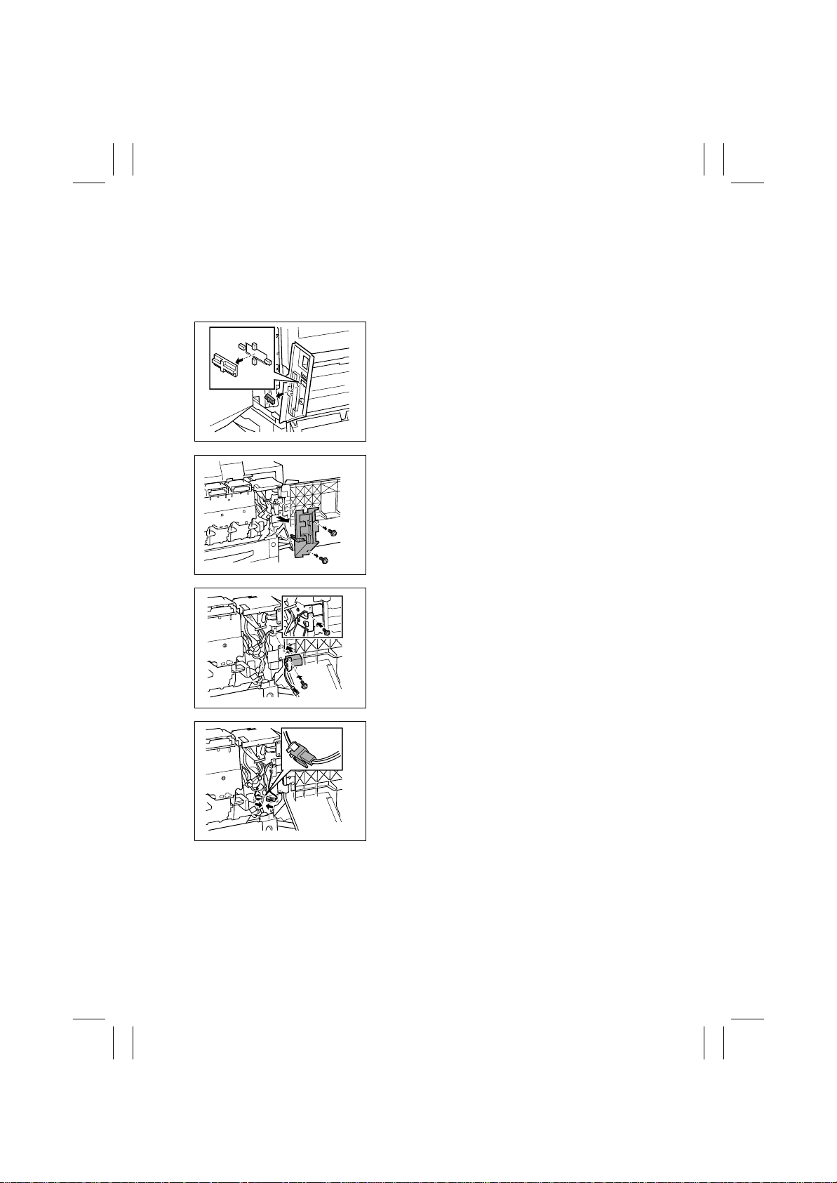
4-1. INSTALLATION OF THE MECHANICAL COUNTER (OPTION)
1. Open the Front Door.
2. Remove the Panel Cover.
3. Open the Right Door.
4. Cut out the knockout in the Front Right Cover.
C4004U267AA
5. Remove two screws and the Right Front Cover .
C4004U268AA
C4004U269AA
C4004U270AA
6. Secure the mechanical counter with one screw.
7. Connect one connector.
D-70
Page 73
FrameMaker Ver.5.5E(PC) 8020/8031 DIS/REASSEMBLY, ADJUSTMENT
02.08.19
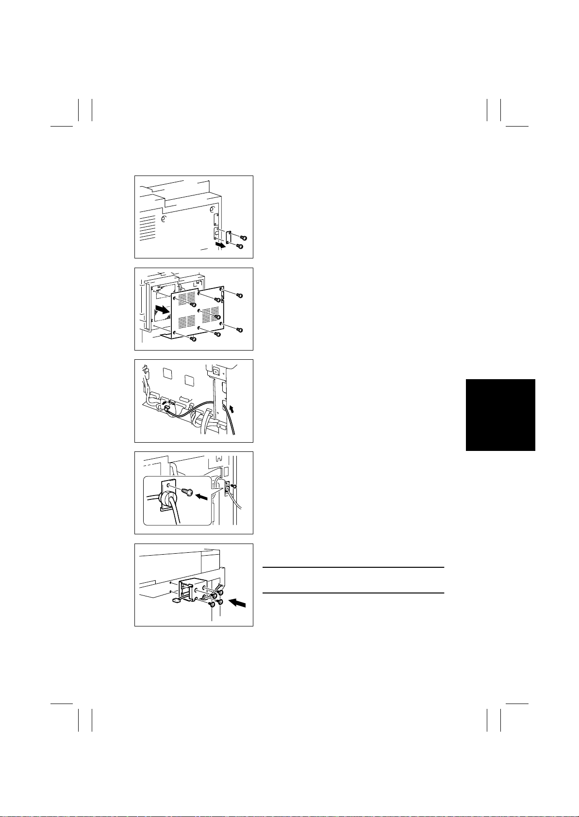
4-2. HOW TO INSTALL THE KEY COUNTER (OPTION)
1. Remove the lower cover.
4004D233AA
2. Remove the rear cover.
4004D234AA
3. Let the wiring through the hole in figure and seat
it.
4025D133AA
4004D244AA
4025D129AA
4. Mount the cord bushing and cord holder and fix
them with a setscrew.
5. Connect connector to PJ14 on PWB-IO.
6. Install the rear cover.
7. Install the key counter mounting plate on the right
side of the copier stand with 4 setscrews.
NOTE
Install the plate with the connector inside the plate.
D-71
Page 74
FrameMaker Ver.5.5E(PC) 8020/8031 DIS/REASSEMBLY, ADJUSTMENT
02.08.19
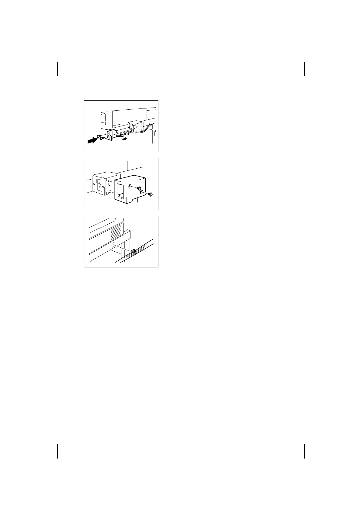
8. Connect a connector of the key counter socket.
9. Install the key counter socket with 4 setscrews.
4025D130AA
10. Install the key counter cover with 2 setscrews.
4025D131AA
11. Attach the cord clamp on the copier stand and fix
the wiring.
12. Access the Security mode, select Management
Function Choice, Key counter, and then set “Set”.
4025D134AA
D-72
Page 75
FrameMaker Ver.5.5E(PC) 8020/8031 DIS/REASSEMBLY, ADJUSTMENT
02.08.19
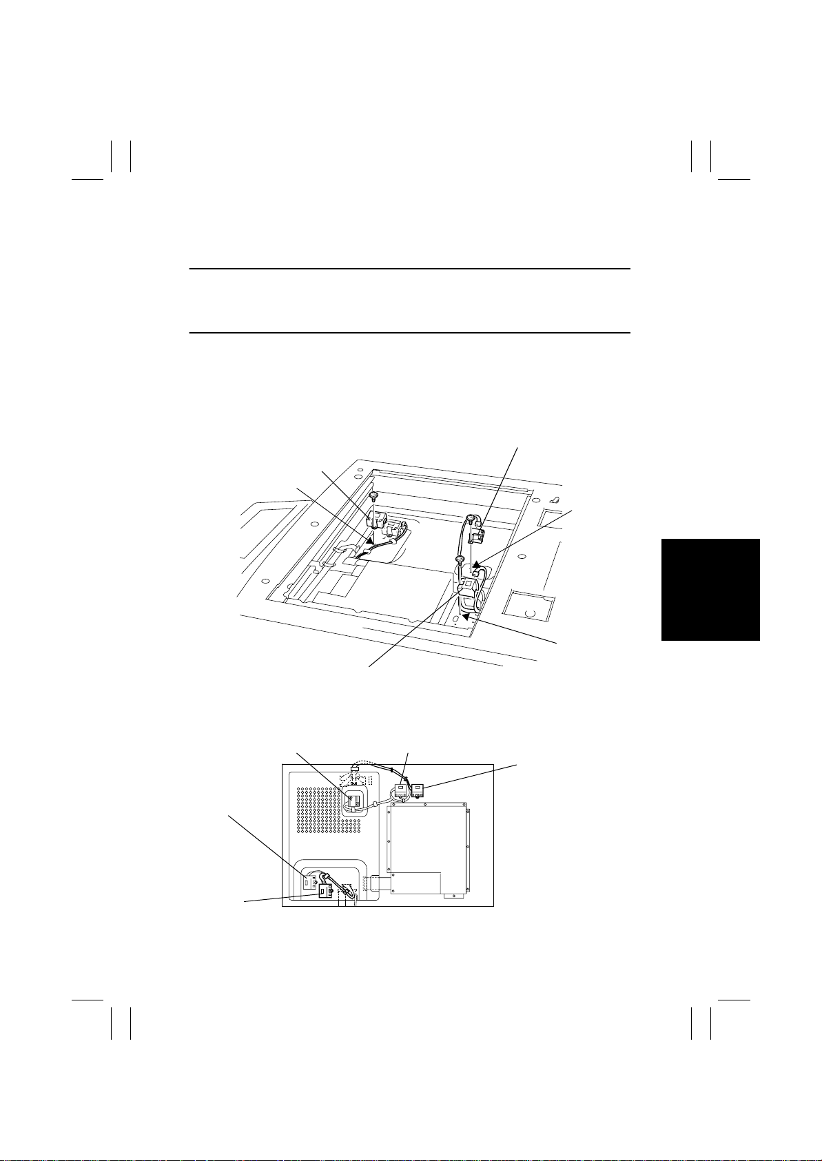
4-3. MOUNTING OF THE ORIGINAL SIZE DETECTING SENSORS
(OPTION)
NOTE
• When an Original Size Detecting Sensor has been added, select “SET” in “Org. Detect
Option Sensor” of “System Input” available from the “Tech. Rep. Mode” and run “Org.
Detect Sensor” of “Machine Adjust.”
1. Remove the IR Right Cover and Original Glass.
2. Remove the PWB Cover.
3. Connect the connector of the Original Size Detecting Sensor to be added to the Image
Processing Board.
4. Replacing the PWB Cover.
5. Mount the Original Size Detecting Sensor (option).
CD2
Optional for the
Europe, U.S.A., Taiwan.
G
FD1
Optional for the U.S.A.
A
4025D138CA
How the Harness should be Placed
FD1
CD1
CD2
E
FD3
Optional for the Europe, U.S.A., Taiwan.
FD2
FD3
4025D109AA
D-73
Page 76
FrameMaker Ver.5.5E(PC) 8020/8031 DIS/REASSEMBLY, ADJUSTMENT
02.08.19
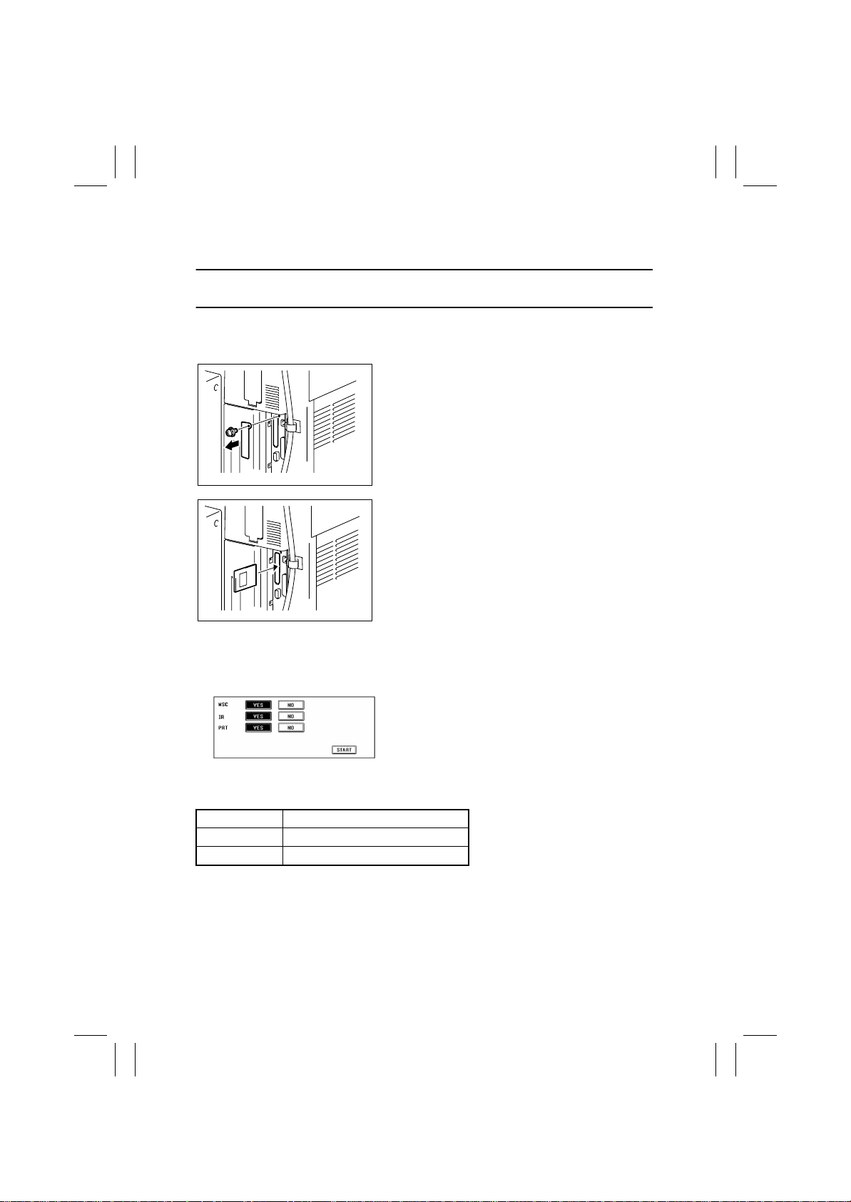
4-4. FLASH MEMORY
• Firmware is upgraded by means of the memory card (IC card).
NOTE
• NEVER remove or insert the memory card with the copier power turned ON.
1. With the Power Switch in the OFF position, unplug the power cord from the power out-
let.
2. Remove one screw and the metal bracket.
4025D110AA
3. Insert the memory card into the slot.
4025D111AA
4. Plug the power cord into the power outlet and turn ON the Powe r Switch.
✽
Three different types of F/W appear on the Touch Panel.
5. Select the particular type of F/W to be updated.
4025P036CB
MSC Image Control Board PWB-F
IR Image Processing Board PWB-C
PRT PIC Board PEB-PIC
D-74
Page 77
FrameMaker Ver.5.5E(PC) 8020/8031 DIS/REASSEMBLY, ADJUSTMENT
02.08.19
6. Press the Start key.
✽
This starts the data rewriting sequence. (At this time, the Start key starts blinking red.)
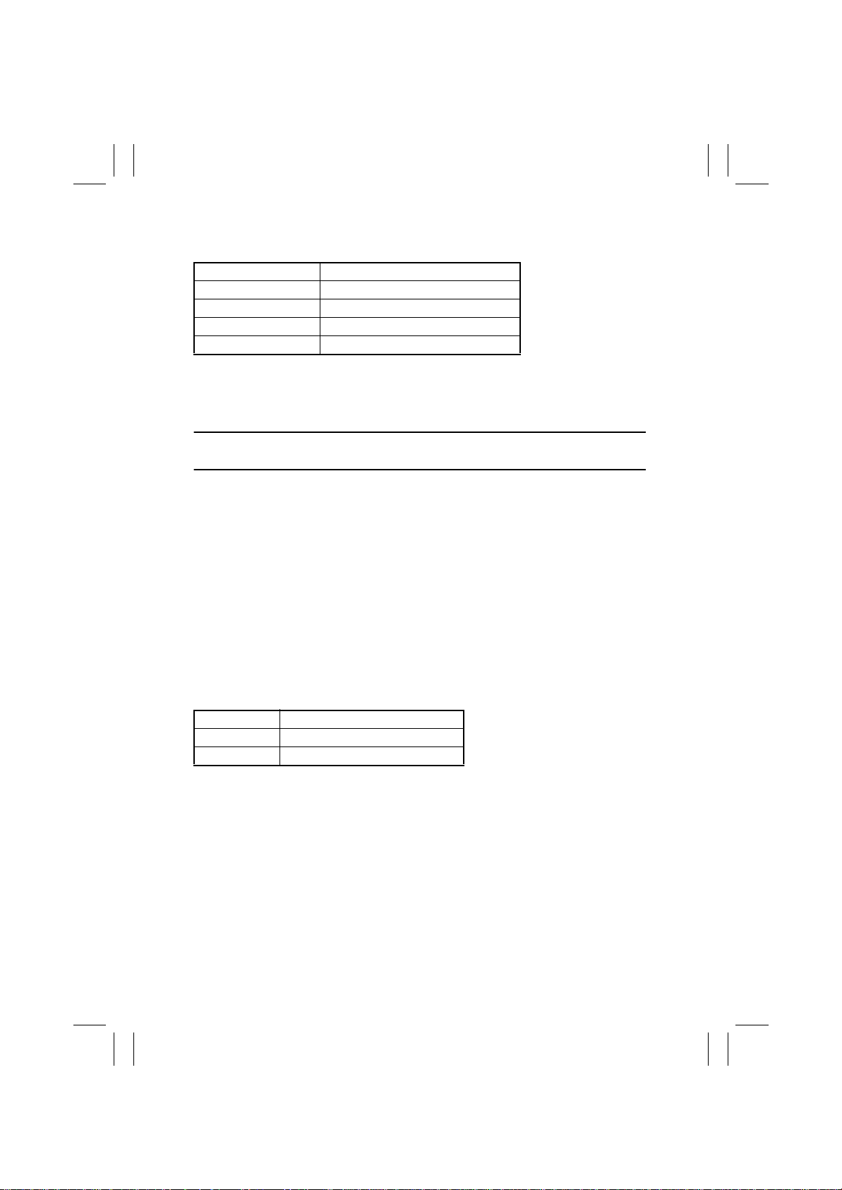
Time Required for Rewriting
Three types at once approx. 20 min.
MSC approx. 1 min. 30 sec.
IR approx. 6 min.
PRT approx. 18 min. 30 sec.
7. Check that the Touch Panel shows the message indicating that the data has been
rewritten correctly (“Downloading Completed”). Check also the Check Sum value
(“Check Sum XXXX”) shown on the Touch Panel. (The Start key lights green.)
8. Unplug the power cord from the power outlet.
NOTE
• Do not turn OFF the Power Switch.
9. Remove the memory card from the slot
10. Turn OFF the Power Switch.
11. Turn ON the Power Switch.
12. Call the Tech. Rep. mode to the screen.
13. Select ROM Version.
14. Check that the ROM version matches the version marked on the memory card.
✽
Action When Data Transfer Fails
If “NG” appears on the Touch Panel, indicating that rewr it ing has been unsuccessful (in
which case the Start key lights up red), take the following steps.
1. Perform the data rewriting procedure again.
2. If the procedure is abnormally terminated, change the memory card for a new one and
try another rewriting sequence.
3. If the procedure is still abnormally term inated, change the board that has caused “NG”
and carry out data rewriting procedure.
MSC Image Control Board PWB-F
IR Image Processing Board PWB-C
PRT PIC Board PEB-PIC
D-75
Page 78
FrameMaker Ver.5.5E(PC) 8020/8031 DIS/REASSEMBLY, ADJUSTMENT
02.08.19
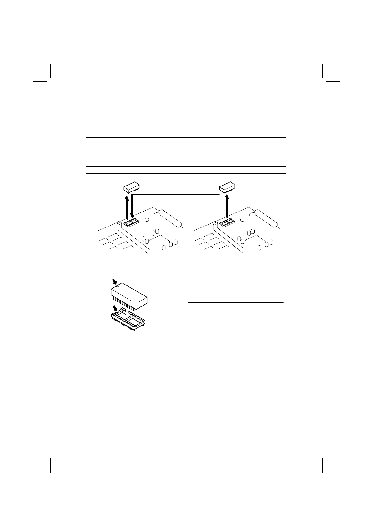
4-5. REMOUNTING RAM IC (IC202)
1. Remove the Image Control Board (PWB-F) from the copier.
2. Demount RAM IC (IC202) from the old Image Control Board (PWB-F).
3. Demount RAM IC (IC202) from the new Image Control Board (PWB-F) and then
remount the old RAM IC (IC202) on the new Image Control Board (PWB-F).
NOTE
• If the Image Control Board (PWB-F) has been replaced and RAM IC (IC202) is not to be
remounted, be sure to record all data of Utility mode and Tech. Rep. mode functions and
make the entries again of these numeric values.
4025D137AA
4025D137AA
NOTE
• Note the alignment notch (A) on RAM IC
when mounting it.
D-76
 Loading...