

Page 1

FrameMaker Ver.5.5E(PC) 8020/8031 M AINTENANCE
02.08.19
MAINTENANCE
Page 2

FrameMaker Ver.5.5E(PC) 8020/8031 M AINTENANCE
02.08.19
Blank page
Page 3
FrameMaker Ver.5.5E(PC) 8020/8031 M AINTENANCE
02.08.19
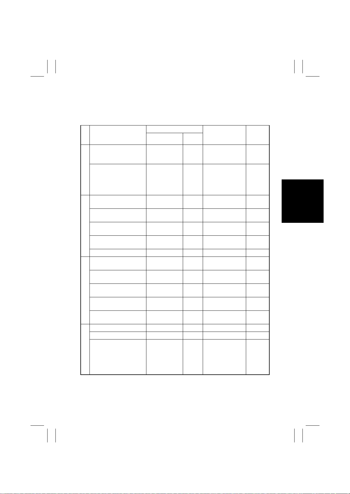
1. MAINTENANCE SCHEDULE
• To ensure that the copier produces good copies and to extend its service life, it is recommended that the maintenance jobs described in this schedule be carried out as
instructed.
PM Parts
Paper Take-Up Roll
Separator Roll Assy
Paper Tak e-Up Section
Synchronizing Roller
Paper Dust Remover
Transport Roller
2nd Image Transfer
Transfer Section
Entrance Upper Guide
Image Transfer Roller Unit — 152 K 65FA-453
Scanner Rail
Mirrors (1st, 2nd, 3rd)
Lens
IR Section
Original Glass
CCD Sensor
Image Transfer Belt Unit — 160 K 65FA-451
Waste Toner Bottle — 30 K 65FA5105
Maintenance Cycle
Clean Replace
When paper
take-up failure
occurs
When paper
take-up failure
occurs
Upon each call
(60 K)
Upon each call
(60 K)
Upon each call
(60 K)
Upon each call
(60 K)
When image
failure occurs
When image
failure occurs
When image
failure occurs
When image
failure occurs
When image
failure occurs
Parts No.
27AE4301✽ (1st)
200 K
111T5101✽ (2nd)
200 K 111T-501
——☞ E-7
152 K 65FA5106
——☞ E-8
——☞ E-8
——☞ E-9
——☞ E-10
——☞ E-11
——☞ E-11
——☞ E-12
Ref. P age
Manual
✽
✽
✽ ☞
✽ ☞
✽ ☞
in This
☞
E-5
☞
E-5
☞
E-6
☞
E-7
☞
E-8
E-18
E-19
E-13
Around waste toner
collecting port
Image Transfer Section
Upon each call — —
E-1
☞
E-14
Page 4
FrameMaker Ver.5.5E(PC) 8020/8031 M AINTENANCE
02.08.19
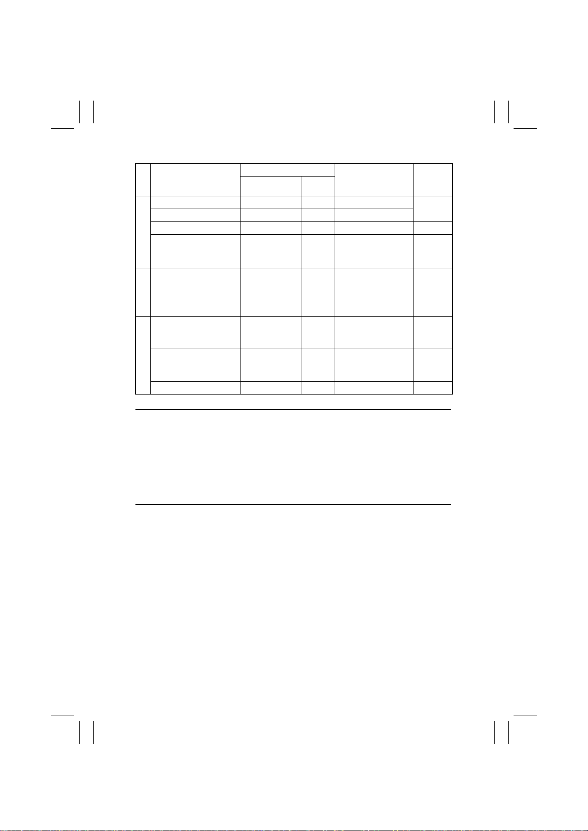
PM Parts
Imaging Unit C/M/Y — 52 K —
Imaging Unit Bk — 82 K —
Ozone Filter — 152 K 65FA5106
Comb electrode
Developing Section
LPH Assy
LPH Section
Fusing Unit — 152 K
Fusing Entrance
Guide Plate
Fusing Section
Deodorant Filter — 10 K 65FA5107
NOTES
• Replace the Paper Take-Up Roll and Separator Roll at the same time.
• Replace the Paper Dust Remover and Ozone Filter at the same time.
• When the Deodorant Filter is replaced, also replace the Bk Toner Cartridge (that comes
with the Deodorant Filter).
• When the Toner Cartridge is replaced, also clean the Comb electrode.
• The numeric values in the Maintenance Cycle column represent the Life Counter values.
• The contents of this maintenance schedule are subject to change without notice.
• Ozone filter and Paper dust remover are setup together as a kit.
Maintenance Cycle
Clean Replace
10 K or
When image
failure occurs
Upon each call
or replacement
of IU
When
malfunction
occurs
Parts No.
——☞ E-15
——☞ E-16
65FA-530✽ (100 V)
65FF-530✽ (230 V)
65FE-530✽ (120 V)
——☞ E-17
Ref. P age
in This
Manual
☞
✽ ☞
☞
✽ ☞
E-22
E-15
E-26
E-17
E-2
Page 5
FrameMaker Ver.5.5E(PC) 8020/8031 M AINTENANCE
02.08.19
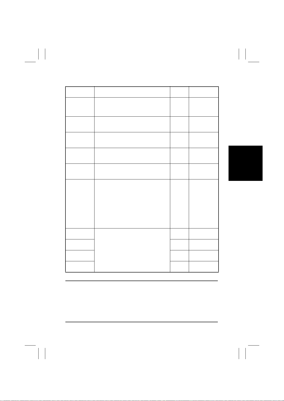
1-1. Guideline for Life Specifications Values by Unit
Description Life Value
Waste Toner
Bottle
Fusing Unit
Paper Dust
Remover
Ozone Filter
Transfer Roller
Unit
Transfer Belt
Unit
Imaging Unit C/
M/Y (8020)
Imaging Unit C/
M/Y (8031)
Imaging Unit Bk
(8020)
Imaging Unit Bk
(8031)
M: minutes
A waste toner full condition is detected when
about 3.5 K (
made after a waste toner near-full condition has
been detected.
The number of copies made is counted.
(The counter counts up 2 for paper whose
FD exceeds 216 mm.)
The number of copies made is counted.
(The counter counts up 2 for paper whose
FD exceeds 216 mm.)
The number of copies made is counted.
(The counter counts up 2 for paper whose
FD exceeds 216 mm.)
The number of copies made is counted.
(The counter counts up 2 for paper whose
FD exceeds 216 mm.)
• The number of copies made is counted.
(The counter counts up 2 for paper whose
FD exceeds 216 mm.)
• The number of copies made is compared
with the value of the number of hours
through which the belt has turned translated to a corresponding value of the
number of copies made and the value,
whichever reaches the life specifications
value, is detected.
The number of hours through which the PC
Drum has turned is compared with the number of hours through which the Developing
Roller has turned translated to a corresponding value of the number of hours
through which the PC Drum has turned and
the value, whichev er reaches the lif e specifications value, is detected.
8031)
6.9 K (
8020)
copies are
150 K 152 K
150 K 152 K
150 K 152 K
150 K 152 K*
150 K 160 K
6929 M
(50 K)
3479 M
(50 K)
7627 M
(80 K)
5411 M
(80 K)
new copy/print
cycle is inhibited
— 30 K
7206 M
(52 K)
3618 M
(52 K)
7818 M
(82 K)
5546 M
(82 K)
NOTES
• When the life specifications value (stop) is reached, the initiation of a new copy/print
cycle is inhibited if “User” is selected for “Unit Change” accessed from “System Input”
available under “Tech. Rep. Mode” and the life warning display is given if “Service” is
selected for the same function (“Unit Change”) (except for the Transfer Belt Unit).
• The life specifications values represent the number of copies made or figures equivalent
to it when given conditions (see the Table given below) are met. They can be more or
less depending on the copier operating conditions of each individual user.
E-3
Page 6
FrameMaker Ver.5.5E(PC) 8020/8031 M AINTENANCE
02.08.19
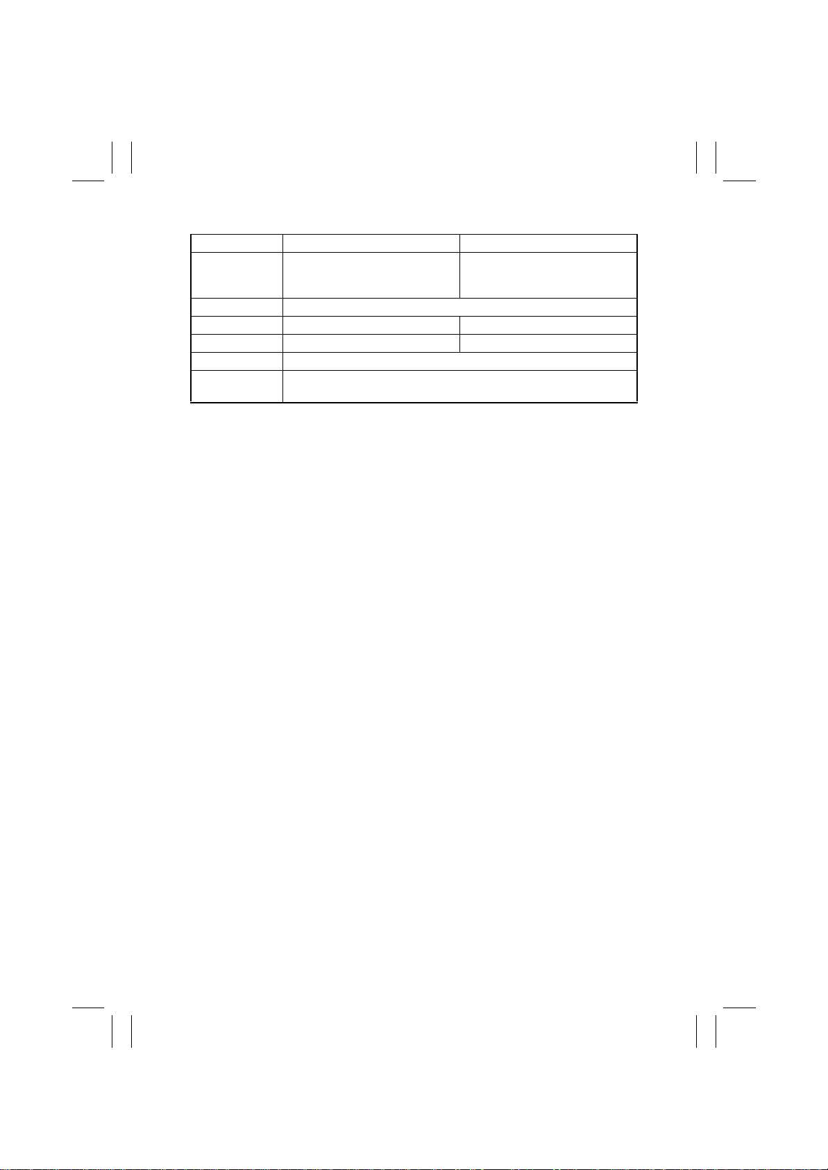
• Conditions for Life Specifications V alues
8031 8020
Job Type Making three copies per job
Paper Size A4C, Letter C
Color Ratio* Color to Black = 6.5 to 1.5 Color to Black = 1.5 to 4.5
CV/M* 8 K 6 K
Original Density B/W = 5 % for each color, 6 % for Monochrome
No. of Operating
Days per Month
*: Varies according to the marketing area.
20 days (Power Switch turned ON and OFF 20 times per month)
Monochrome: Making three
copies per job
Color: Making three copies per job
E-4
Page 7
FrameMaker Ver.5.5E(PC) 8020/8031 M AINTENANCE
02.08.19
2. DISASSEMBLY/REASSEMBLY AND CLEANING
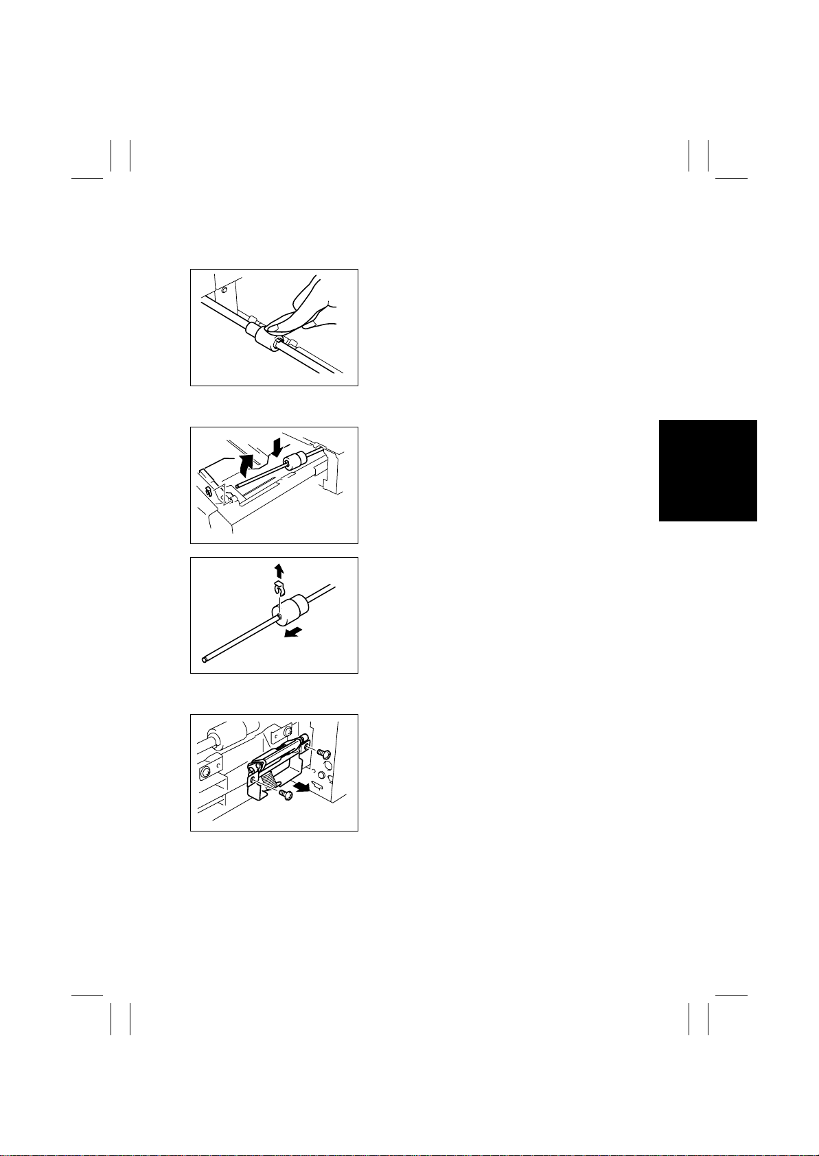
(1) Cleaning of the Paper Take-Up Roll
1. Slide out the drawer.
2. Using a soft cloth dampened with alcohol, wipe
the Paper Take-Up Roll clean of dirt.
4658D005AA
(2) Replacing of the Paper Take-Up Roll
1. Slide out the drawer.
2. Lock the Paper Lifting Plate into position.
3. Snap off one C-crip from the Paper Take-Up Roll
Assy.
4. Slide the Paper Take-Up Roll Assy to the rear and
take its shaft off the front bushing.
4658D008AA
5. Snap off one C-crip and remove the Paper TakeUp Roll.
6. Remove the Paper Separator Roll Assy. [See (4)
Replacement of the Paper Separator Roll Assy.]
7. To reinstall, reverse the order of removal.
8. Select “Tech. Rep. Mode”
and clear the count of “1st” or “2nd.”
4658D009AA
(3) Cleani ng of the Paper Separator Roll
1. Slide out the drawer.
2. Remove two screws and the Paper Separator
Roll mounting bracket assy.
4658D002AA
→
“Counter” → “Life”
E-5
Page 8
FrameMaker Ver.5.5E(PC) 8020/8031 M AINTENANCE
02.08.19
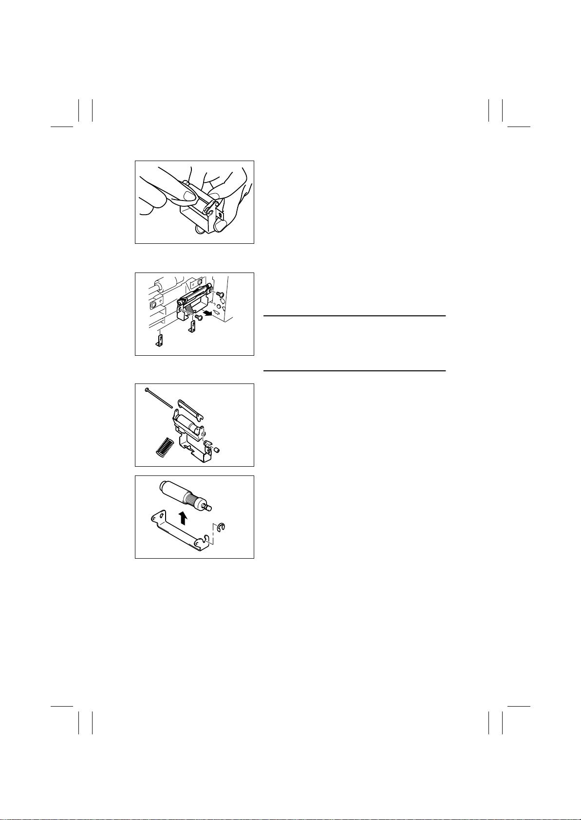
3. Using a soft cloth dampened with alcohol, wipe
the Paper Separator Roll clean of dirt.
4658D006AA
(4) Replacing of the Separator Roll Assy
1. Slide out the drawer.
2. Remove two screws and the Paper Separator
Roll mounting bracket assy and reinforcement
plate.
NOTES
• Receive by hand the reinfo rcement plate that will
4025E001AA
come off position when the screws are removed.
• When reinstalling the reinforcement plate, make
sure that it is doweled into position.
4658D003AA
4658D004AA
3. Take off the rubber stopper, shaft, spring, and
guide plate to remove the Paper Separator Roll
fixing bracket assy.
4. Snap off one E-ring and the Paper Separator Roll
Assy.
5. Remove the Paper Take-Up Roll. [See (2)
Replacement of the Paper Take-Up Roll.]
6. To reinstall, reverse the order of removal.
→
7. Select “Tech. Rep. Mode”
“Counter” → “Life”
and clear the count of “1st.”
E-6
Page 9
FrameMaker Ver.5.5E(PC) 8020/8031 M AINTENANCE
02.08.19
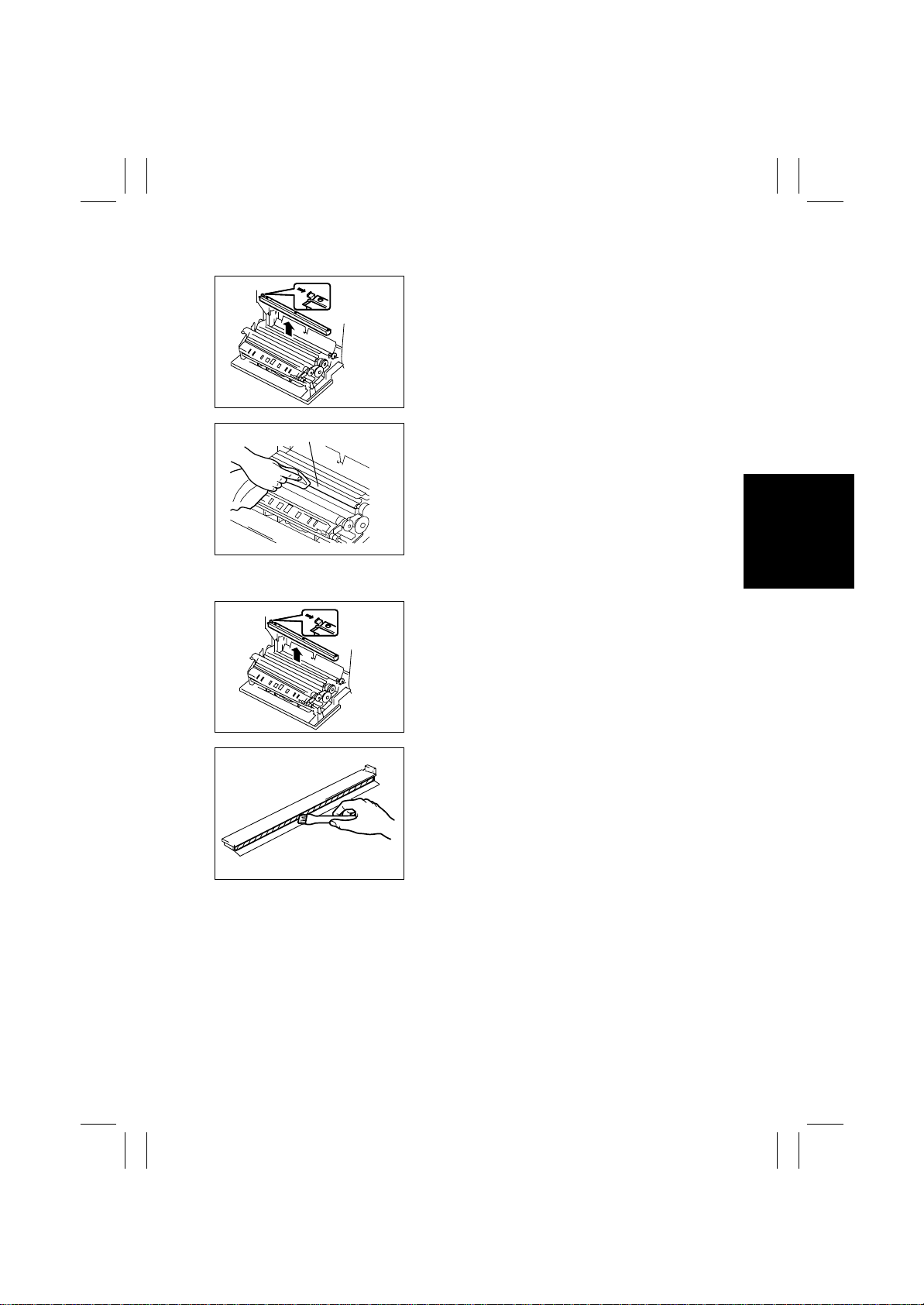
(5) Cleaning of the Synchronizing Rollers
1. Open the Right Door.
2. Remove the Paper Dust Remover.
4004D206AB
Synchronizing Rollers
4004D205AC
3. Using a soft cloth dampened with alcohol, wipe
the Synchronizing Rollers clean of dirt.
(6) Cleaning of the Paper Dust Remover
1. Open the Right Door.
2. Remove the Paper Dust Remover.
4004D206AB
3. Using a brush, whisk dust off the Paper Dust
Remover.
4025E002AA
E-7
Page 10
FrameMaker Ver.5.5E(PC) 8020/8031 M AINTENANCE
02.08.19
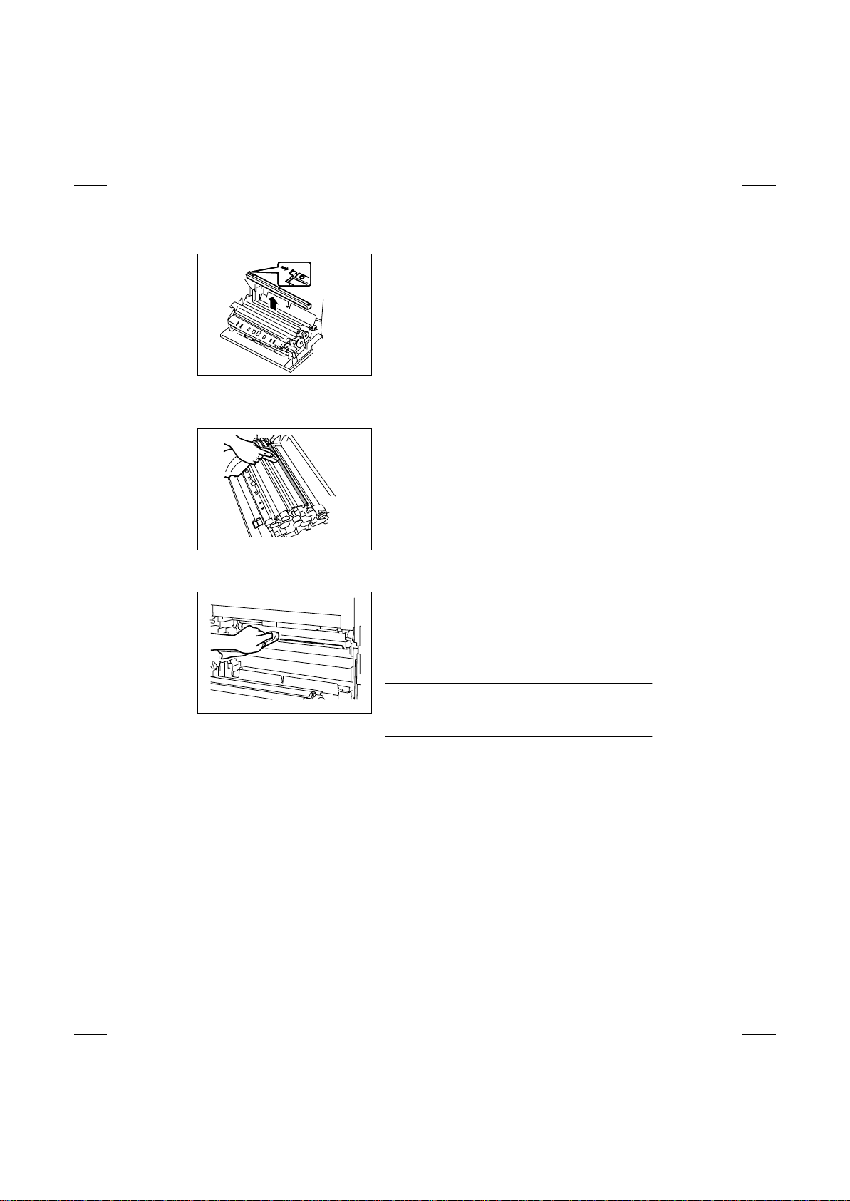
(7) Replacing of the Paper Dust Remover
1. Open the Right Door.
2. Pushing the hook with a blue label inward,
remove the Paper Dust Remover.
3. Remove the Ozone Filter. [See (17) Replacement of the Ozone Filter.]
4. To reinstall, reverse the order of removal.
5. Select “Tech. Rep. Mode”
4004D206AB
and clear the count of “Paper Powder Filter/
Ozone Filter.”
(8) Cleaning of the T ran sport Roller
1. Open the Right Door.
2. Using a soft cloth dampened with alcohol, wipe
the Transpor t Roller clean of dir t.
4025E053AA
→
”Counter” →”Life”
(9) Cleaning of the 2nd Image Transfer Entrance Upper Guide
1. Open the Right Door.
2. Open the Left Door.
3. Remove the Waste Toner Bottle.
4. Slide the Transfer Belt Unit out halfway.
5. Wipe the 2nd Image Transfer Entrance Upper
Guide clean of dirt using a soft cloth.
4025E055AA
NOTE
• When cleaning, use care not to be hurt by the
leading edge of the guide that is sharp.
E-8
Page 11
FrameMaker Ver.5.5E(PC) 8020/8031 M AINTENANCE
02.08.19
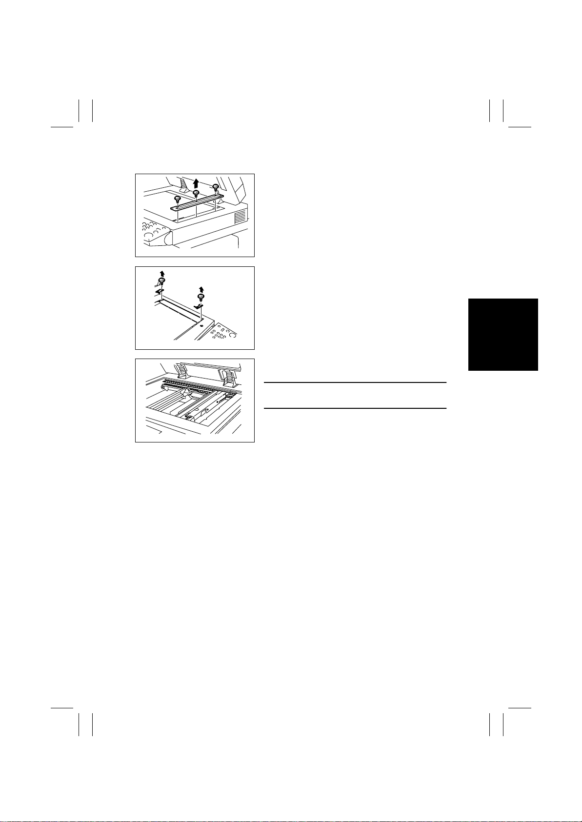
(10) Cleaning of the Scanner Rails
1. Remove three screws and the IR Right Cover.
k4025E003AA
2. Remove one screw each and the Original Glass
fixing bracket (at the front and rear).
3. Remove the Original Glass.
k4025E004AA
4. Using a soft cloth dampened with alcohol, wipe
the Scanner Rails clean of dirt.
4025E005AA
NOTE
• Apply lubricant after cleaning.
E-9
Page 12
FrameMaker Ver.5.5E(PC) 8020/8031 M AINTENANCE
02.08.19
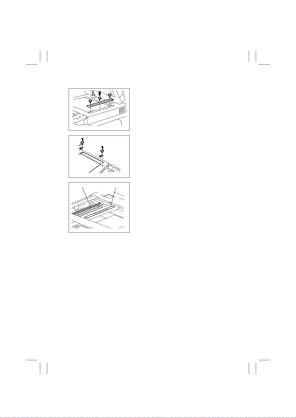
(11) Cleaning of the Mirrors (1st/2nd/3rd)
1. Remove three screws and the IR Right Cover.
k4025E003AA
2. Remove one screw each and the Original Glass
fixing bracket (at the front and rear).
3. Remove the Original Glass.
k4025E004AA
1st Mirror2nd/3rd Mirror
40004D199AA
4. Using a soft cloth dampened with alcohol, wipe
mirrors clean of dirt.
E-10
Page 13
FrameMaker Ver.5.5E(PC) 8020/8031 M AINTENANCE
02.08.19
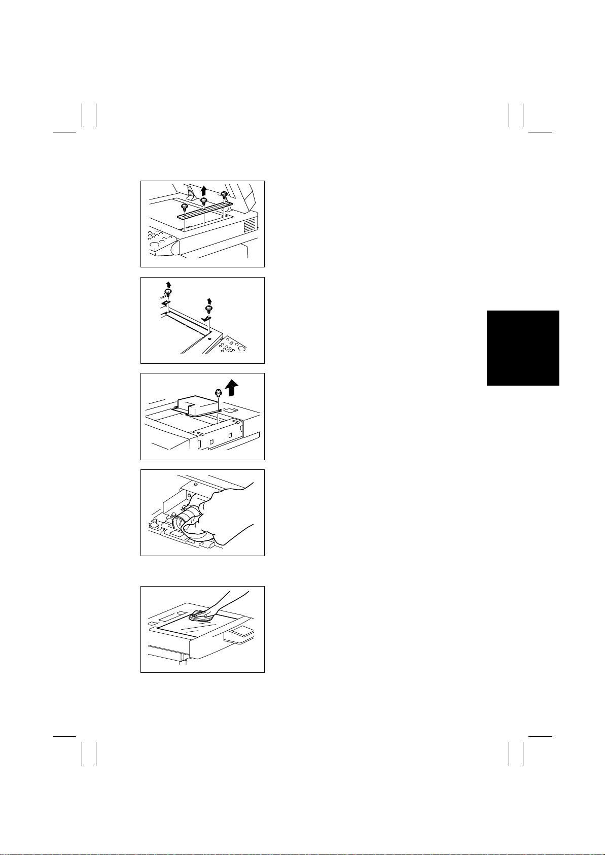
(12) Cleaning of the Lens
1. Remove three screws and the IR Right Cover.
k4025E003AA
2. Remove one screw each and the Original Glass
fixing bracket (at the front and rear).
3. Remove the Original Glass.
k4025E004AA
4. Remove fourteen screws and the optical cover.
4025E006AB
4004D200AB
(13) Cleaning of the Original Glass
4004D201AA
5. Using a soft cloth dampened with alcohol, wipe
the Lens clean of dirt.
1. Using a soft cloth dampened with alcohol, wipe
the Original Glass clean of dirt.
E-11
Page 14
FrameMaker Ver.5.5E(PC) 8020/8031 M AINTENANCE
02.08.19
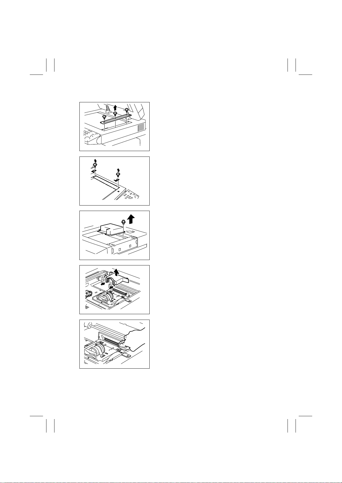
(14) Cleaning of the CCD Sensor
1. Remove three screws and the IR Right Cover.
k4025E003AA
2. Remove one screw each and the Original Glass
fixing bracket (at the front and rear).
3. Remove the Original Glass.
k4025E004AA
4. Remove fourteen screws and the optical cover.
4025E006AB
4025E050AA
4025E051AA
5. .Remove two hooks and the lens cover.
6. Using a soft cloth dampened with alcohol, wipe
the CCD Sensor clean of dirt.
E-12
Page 15
FrameMaker Ver.5.5E(PC) 8020/8031 M AINTENANCE
02.08.19
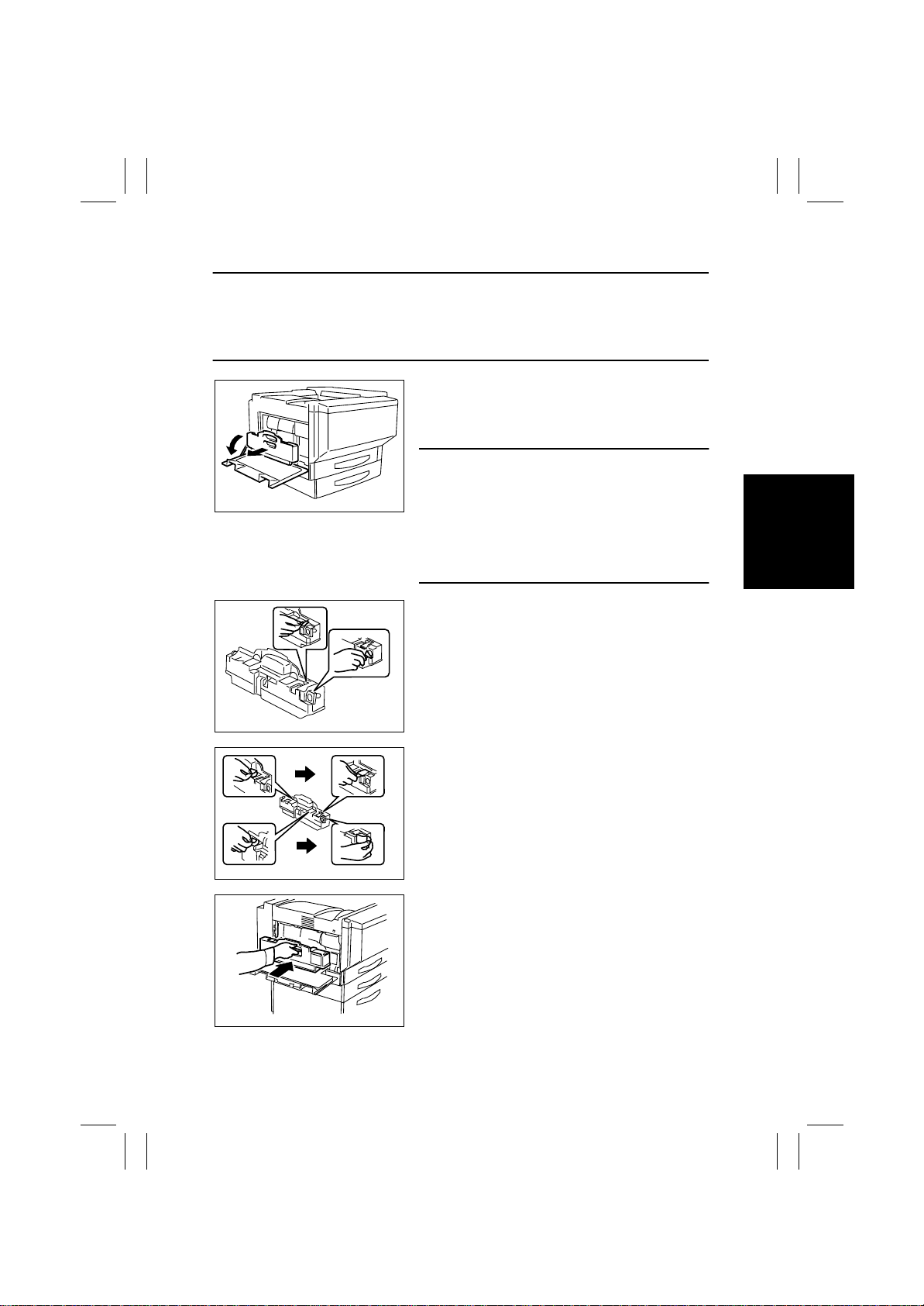
(15) Replacing the Waste Toner Bottle
NOTES
• If the Paper exit system option is installed, remove if from the main unit before replacing
the waste toner bottle.
• When removing the paper exit system option, support the horizontal transport unit with
your hand to prevent if from dropping.
1. Turn OFF the main switch.
2. Open the Left Door.
3. Grasp the handle, and remove the waste toner
bottle.
NOTES
• Raise the waste toner bottle gently before remov-
4004D221AA
ing it.
• If scattered toner has accumulated in the vicinity of
the toner collecting port, do not tilt the waste toner
bottle when removing it.
• Do not leave the waste toner bottle in a til ted condi-
tion after removing it.
4025E008AA
4025E007AA
4025E009AA
4. Remove the seals from the two toner collecting
ports.
5. Peel off the seals for blocking the two toner collecting ports, and place them over the toner collecting ports.
6. Clean the surface around the waste toner collecting port. [See (16) Cleaning of the Area around
the Waste Toner Collecting Port.]
7. Remove the waste toner bottle from its box, and
remove the packing material.
8. Grasp the handle, and set the waste toner bottle
in place.
E-13
Page 16
FrameMaker Ver.5.5E(PC) 8020/8031 M AINTENANCE
02.08.19
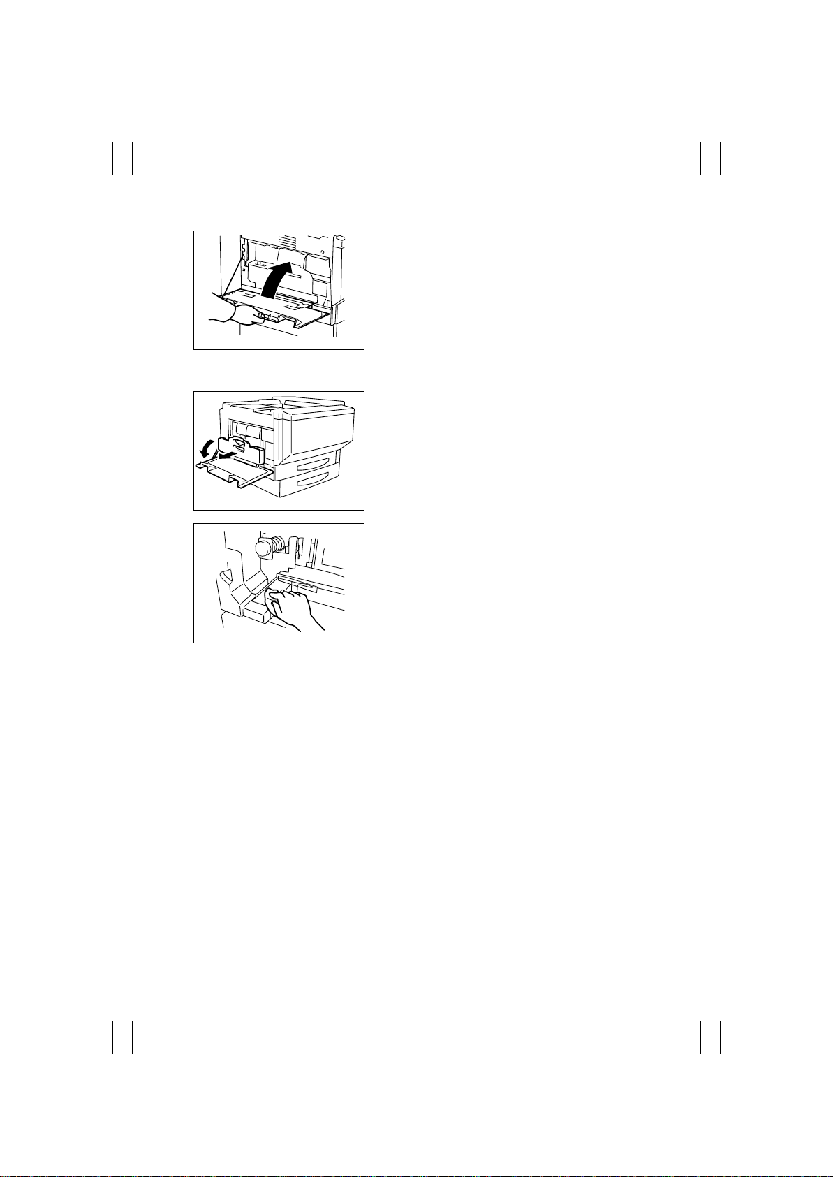
9. Close the Left Door.
4025E010AA
(16) Cleaning of the Area around the Waste Toner Collecting Port
1. Open the Rear Left Cover.
2. Remove the Waste Toner Bottle.
4004D221AA
3. Wipe the areas around the Waste Toner Collecting Port clean of spilled toner and dirt using a soft
cloth dampened with water or alcohol.
4004D222AB
E-14
Page 17
FrameMaker Ver.5.5E(PC) 8020/8031 M AINTENANCE
02.08.19
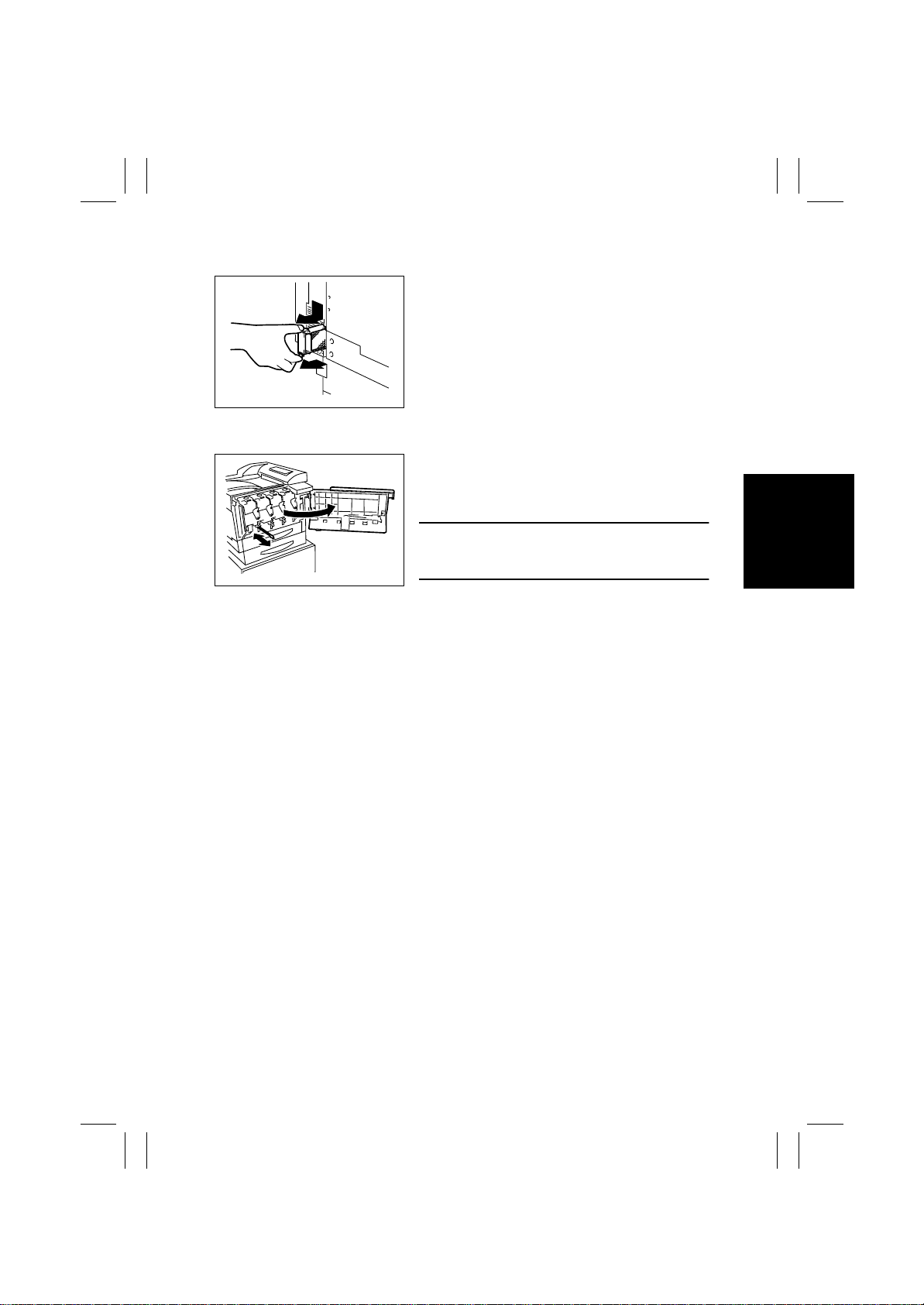
(17) Replacing Ozone Filter
1. Holding onto the hook, remove the Ozone Filter.
2. Remove the Paper Dust Remover. [See (7)
Replacement of the Paper Dust Remover.]
3. To reinstall, reverse the order of removal.
4. Select “Tech. Rep. Mode”
and clear the count of “Paper Powder Filter/
Ozone Filter.”
4025E011AA
→
“Counter”→”Life”
(18) Cleaning of the Comb Electrode
1. Open the Front Door.
2. Clean the Comb Electrode by moving the Comb
NOTE
• Move the Comb Electrode Cleaning Lever slowly
4025E012AA
Electrode Cleaning Lever to the front and rear
three round trips.
forward and backward until it stops.
E-15
Page 18
FrameMaker Ver.5.5E(PC) 8020/8031 M AINTENANCE
02.08.19
(19) Cleaning LPH Assy
NOTE
• After the IU has been slid out, be sure to place it in the aluminum pack for packing or
wrap it in the light shielding cloth and store it in a dark place. Do not leav e the IU to stand
for a l ong time.
1. Open the Front Door.
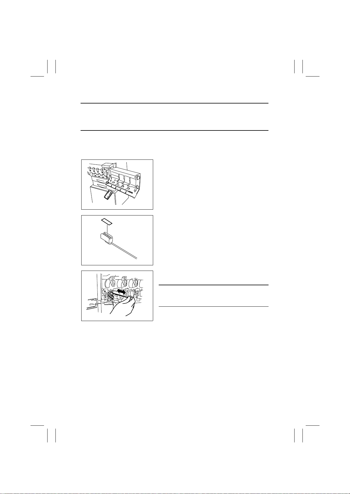
2. Slide out the IU (C/M/Y/Bk).
☞
E-22
3. Remove the LED Cleaning Jig and LED Cleaning
Jig Pad.
4025E014AA
4. Affix the LED Cleaning Jig Pad to the LED Cleaning Jig.
4025E015AA
4025E013AA
5. Clean the LED of the LPH Assy by moving the
LED Cleaning Jig three reciprocating motions.
NOTE
• Use only the specified jig (LED Cleaning Jig) for
cleaning.
E-16
Page 19
FrameMaker Ver.5.5E(PC) 8020/8031 M AINTENANCE
02.08.19
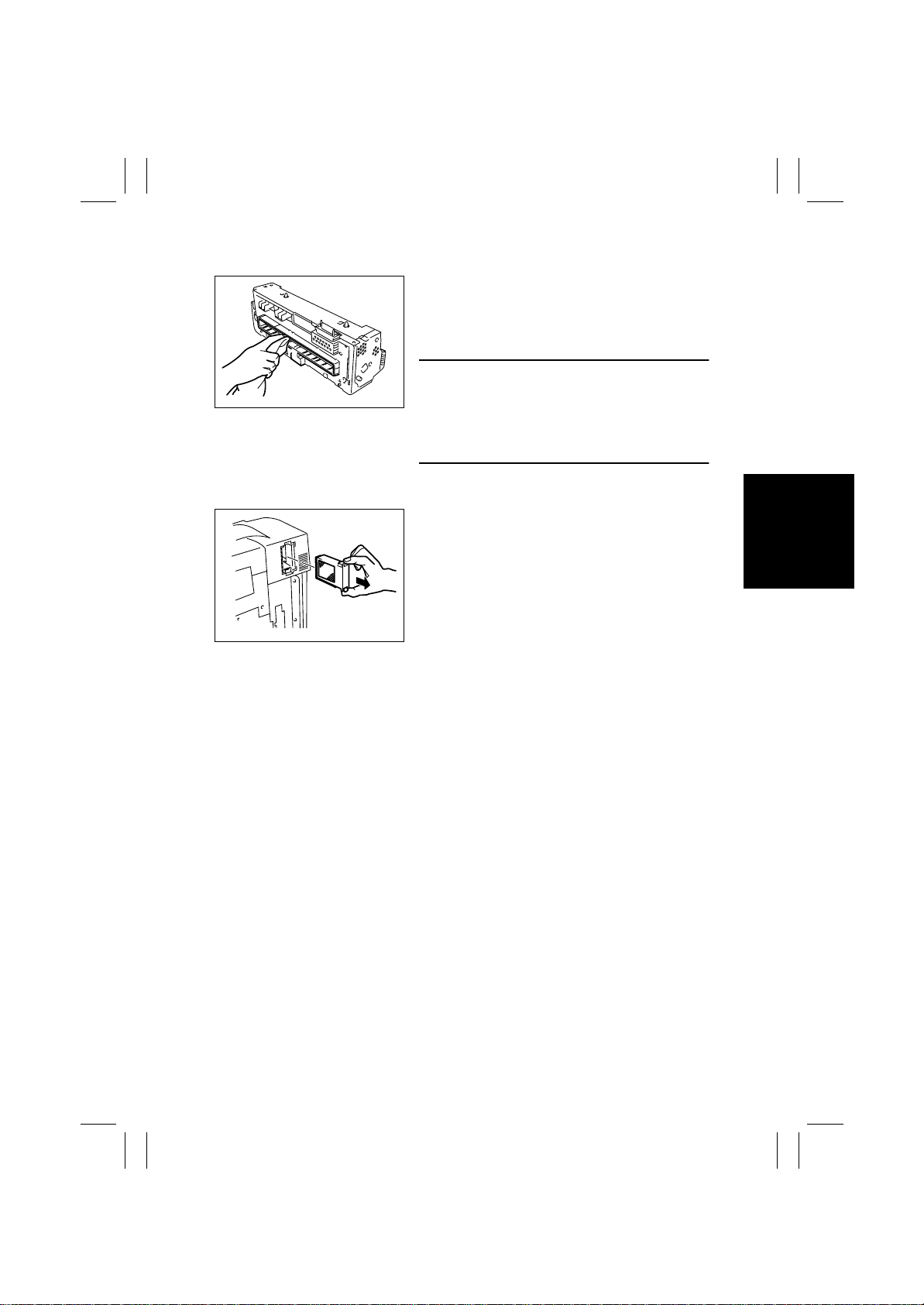
(20) Cleaning of the Fusing Entrance Guide Plate
1. Remove the Fusing Unit.
☞
E-26
2. Using a soft cloth or cotton swab dampened with
alcohol, wipe clean the Fusing Entrance Guide
Plate.
NOTES
4025E016AA
• Use care when cleaning the Fusing Entrance
Guide Plate as it is easy to damage.
• Be careful that the Fusing Unit can be hot.
• Do not place the Fusing Unit on a workbench with
its terminal down.
(21) Replacemen t of the Deodoran t Filter
1. Holding onto the hook, take out the Deodorant
Filter.
4025E017AA
E-17
Page 20
FrameMaker Ver.5.5E(PC) 8020/8031 M AINTENANCE
02.08.19
3. Replacing the Units
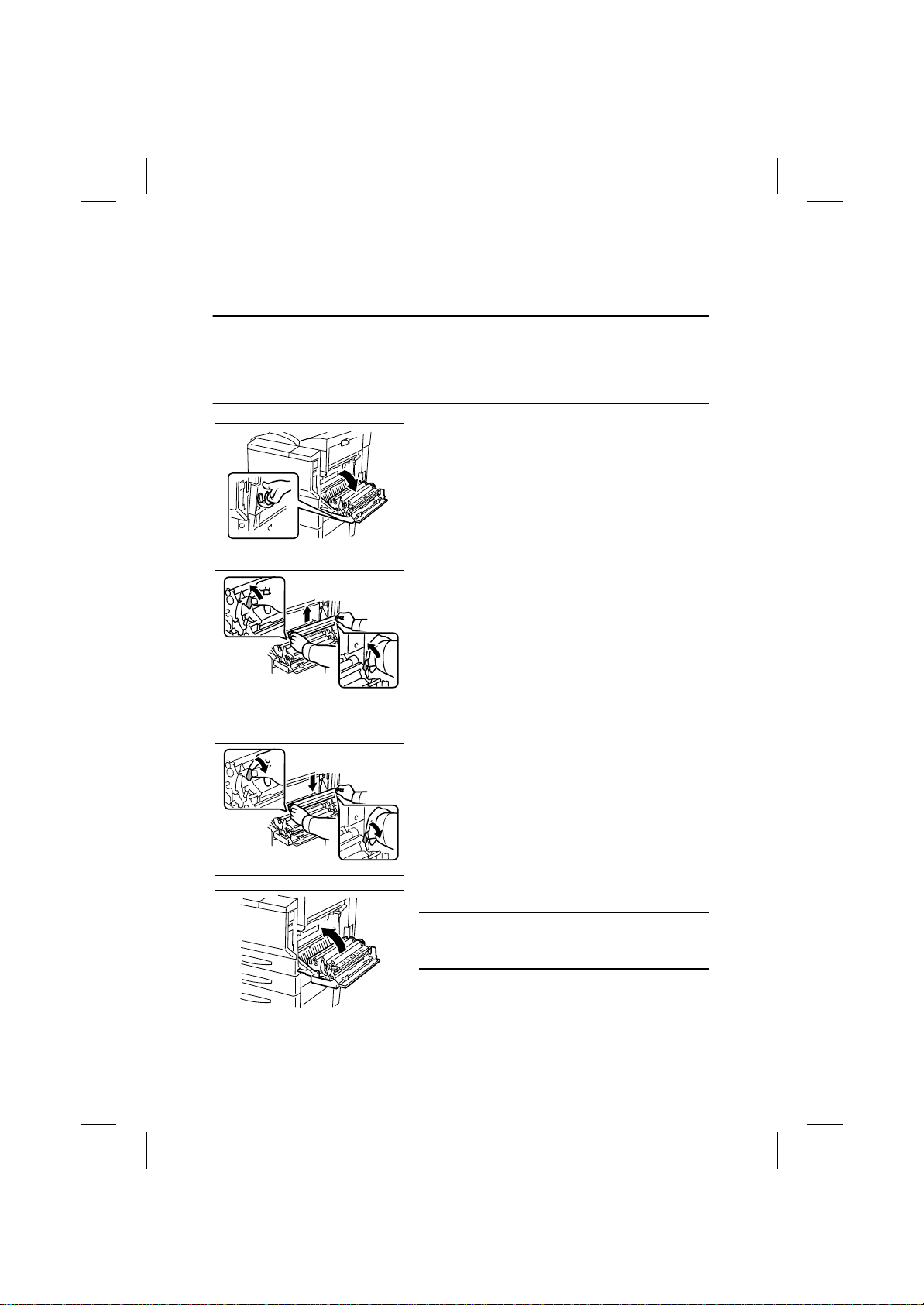
(1) Replacing the Image Transfer Roller Unit
Removal Procedure
NOTES
• If the Paper exit system option is installed, remove if from the main unit before replacing
the waste toner bottle.
• When removing the paper exit system option, support the horizontal transport unit with
your hand to prevent if from dropping.
1. Turn OFF the main switch.
2. Open the Right Door.
4025E018AA
3. Unlock the blue lock levers (at two places).
4. Holding onto the blue lock levers (at two places),
remove the Image Transfer Roller Unit.
Reinstallation Procedure
4025E019AB
4025E020AB
4025E021AA
1. Holding onto the blue lock levers (at two places),
mount the Image Transfer Roller Unit.
2. Lock the blue lock levers (at two places).
3. Close the Right Door.
NOTE
• Make sure that the door is locked in position both
at front and rear.
4. Turn ON the Power Switch.
5. Select “Tech. Rep. Mode”
→
“Counter” → “Life”
and clear the count of “Transfer Roller Unit.”
E-18
Page 21
FrameMaker Ver.5.5E(PC) 8020/8031 M AINTENANCE
02.08.19
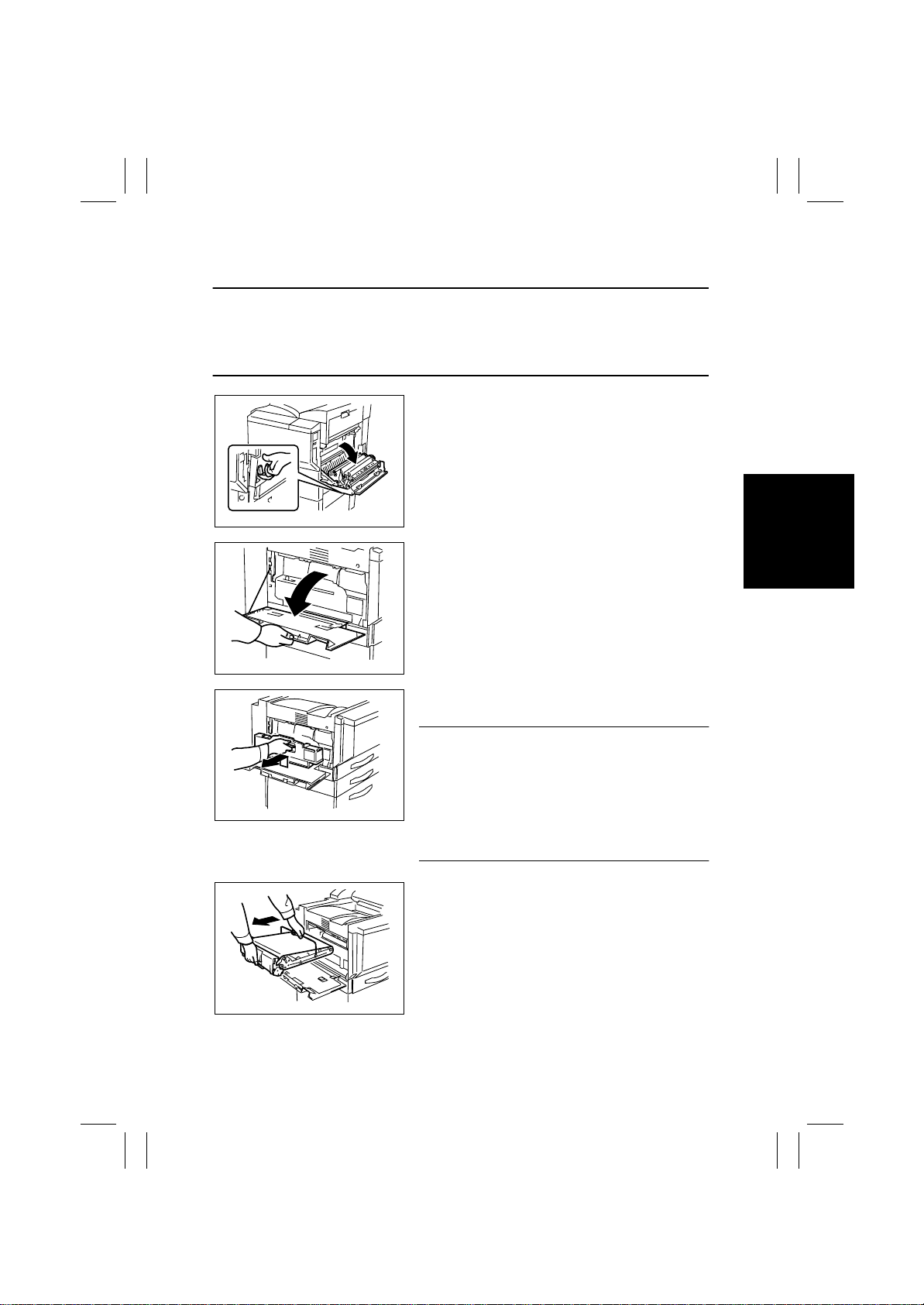
(2) Replacing the Image Transfer Belt Unit
Removal Procedure
NOTES
• If the Paper exit system option is installed, remove if from the main unit before replacing
the waste toner bottle.
• When removing the paper exit system option, support the horizontal transport unit with
your hand to prevent if from dropping.
1. Turn OFF the main switch.
2. Open the Right Door.
4025E018AA
3. Open the Left Door.
4025E022AA
4025E023AA
4025E024AA
4. Grasp the handle, and remove the waste toner
bottle.
NOTES
• Raise the waste toner bottle gently before remov-
ing it.
• If scattered toner has accumulated in the vicinity of
the toner collecting port, do not tilt the waste toner
bottle when removing it.
• Do not leave the waste toner bottle in a til ted condi-
tion after removing it.
5. Pull out the Image Transfer Belt Unit.
E-19
Page 22
FrameMaker Ver.5.5E(PC) 8020/8031 M AINTENANCE
02.08.19
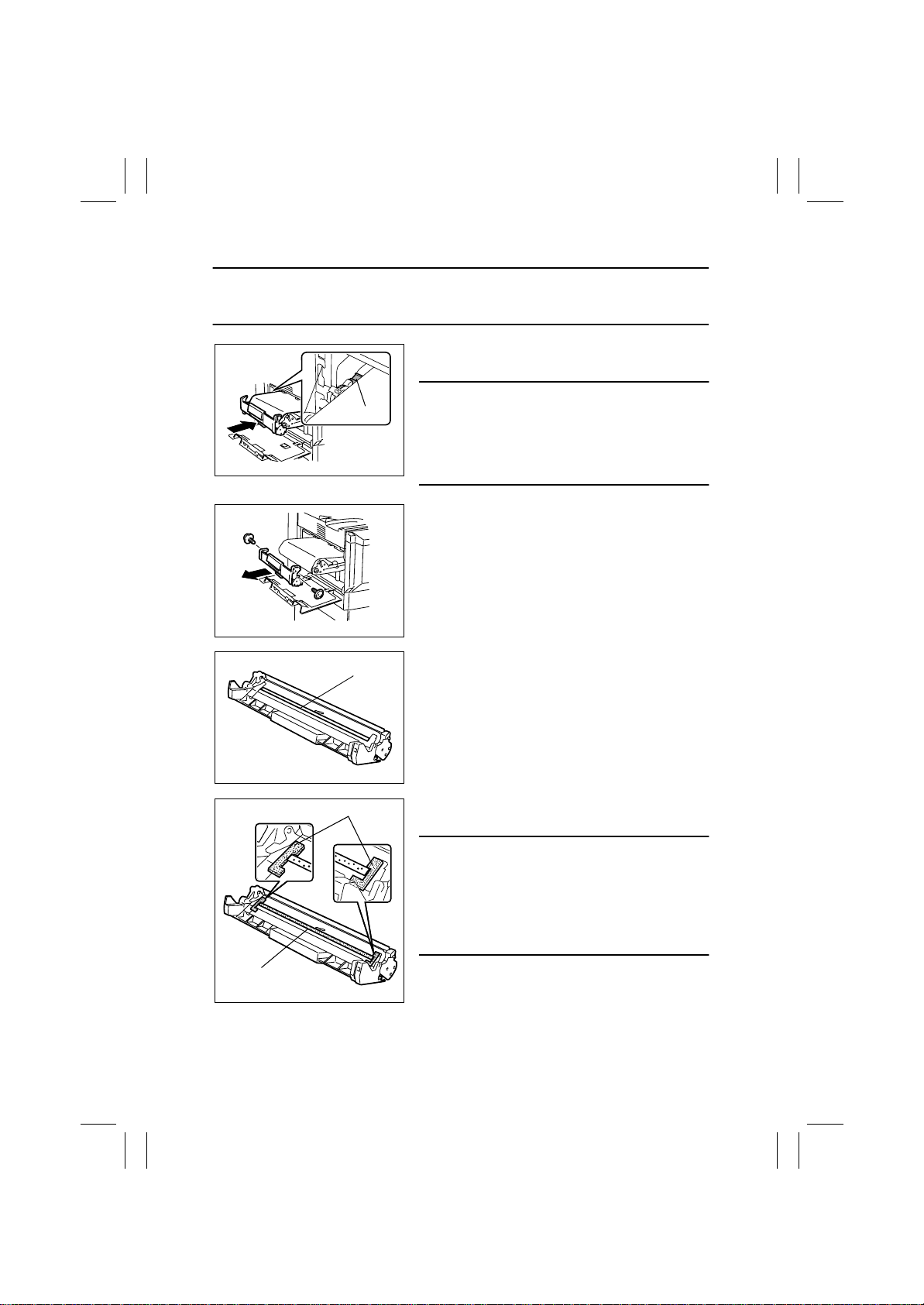
Reinstallation Procedure
NOTE
• When installing the Transfer Belt Unit, use care not to touch the T r ansf er Film with hands.
(Fingerprints on the Transfer Film result in image problems.)
1. Insert the Transfer Belt Unit halfway up to the
point shown on the left.
NOTES
Terminal
• Note the arrow label provided at the guide on the
copier side when inserting the Transfer Belt Unit.
• Insert the Transfer Belt Unit until its terminal is
4025E027AB
stopped at the cutout in the guide on the copier
side.
2. Supporting the Transfer Cleaner Assy with a
hand, remove two screws.
3. Remove the Transfer Cleaner Assy.
4. Remove protective paper taped to the Transfer
Cleaner Assy .
Brush
4025E028AA
Brush
4025E029AA
Side Seals
4025E030AA
5. Turn over the Transfer Cleaner Assy so that the
brush faces upward.
6. Uniformly apply the enclosed toner along the
brush and on the side seals.
NOTE
• Save a small amount of toner for use in the subse-
quent step.
• Apply toner directly to the top of the side seals.
Otherwise, the side seals could be worn or a noise
could be produced when the image transfer belt
moves.
E-20
Page 23
FrameMaker Ver.5.5E(PC) 8020/8031 M AINTENANCE
02.08.19
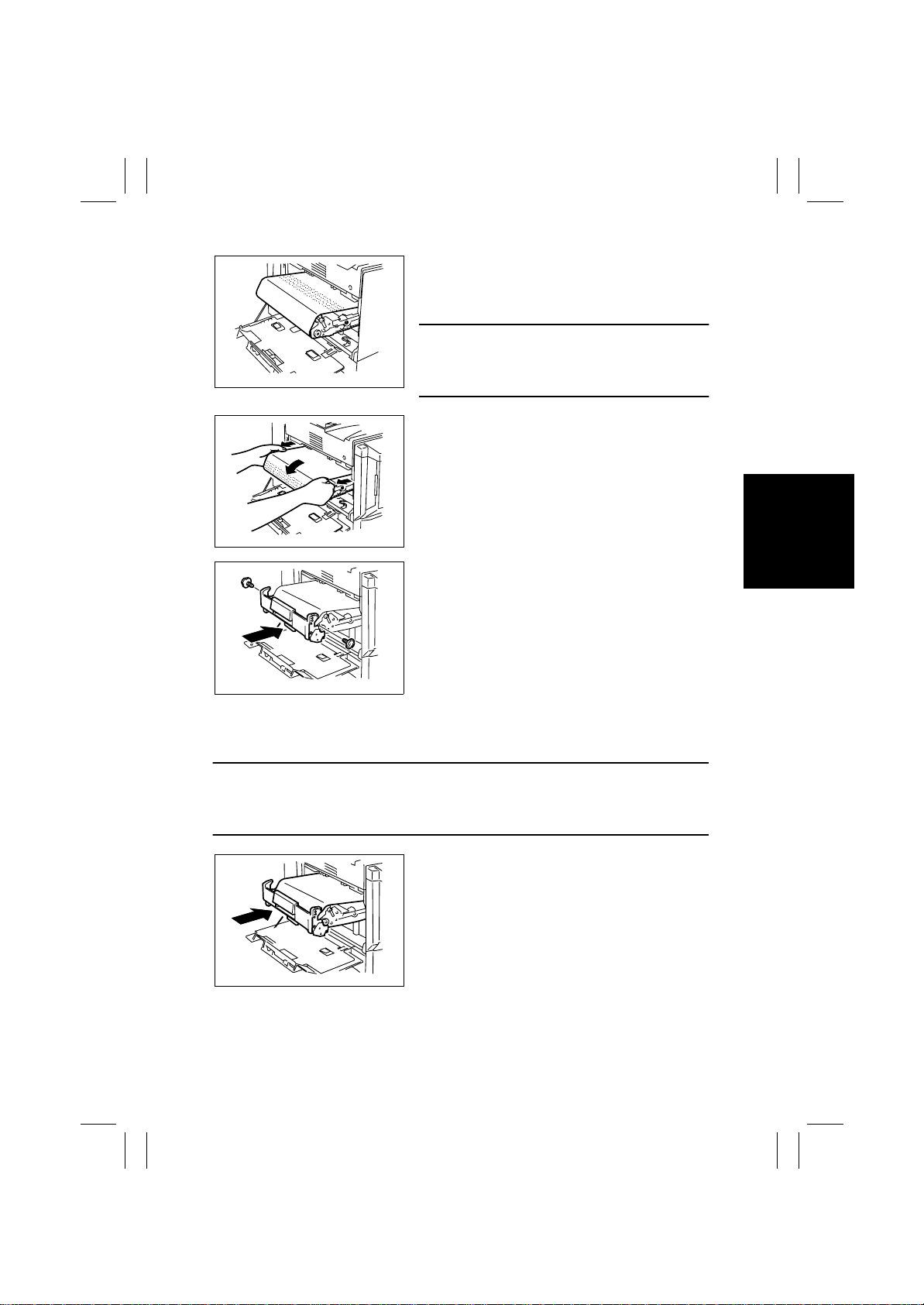
7. Place the remainder toner on the paper towel that
comes with the Transfer Belt Unit and apply an
even coat of toner on the Transfer Belt (up to 15
mm from both edges).
NOTE
• The toner, even if there is still the remainder left,
4025E031AA
should not be used for the copier. It is different
from what is used with the copier.
8. Holding onto both ends of the Transfer Belt, pull
the Transfer Belt until the Blade of the Transfer
Cleaner Assy contacts the location in the belt, to
which toner has been applied.
4025E032AA
9. Fit bosses (at the front and rear) of the Transfer
Cleaner Assy into the hooks (at the front and
rear) of the Transfer Belt Unit.
10. Secure the Transfer Cleaner Assy to the Transfer
Belt Unit using two screws.
4025E033AA
11. Holding onto both ends of the Transfer Belt, turn the Transfer Belt one complete turn in
the same direction as in step 8 and check the Blade for improper contact, failure to
remove toner completely off, noise, and overload.
NOTES
• If any faulty symptom is evident, apply toner to the Transfer Belt again.
• If the Blade fails to remove toner completely off the Transfer Belt, perform step 11 once
again.
12. Insert the Image Transfer Belt Unit.
4025E052AA
E-21
Page 24
FrameMaker Ver.5.5E(PC) 8020/8031 M AINTENANCE
02.08.19
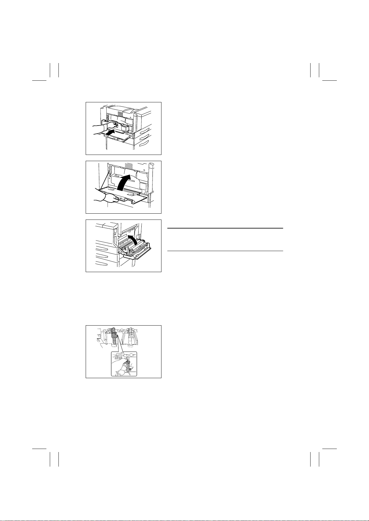
13. Hold the handle and install the Waste Toner Bottle in position.
4025E009AA
14. Close the Left Door.
4025E010AA
15. Close the Right Door.
NOTE
• Make sure that the door is locked in position both
at front and rear.
16. Turn ON the Power Switch.
4025E021AA
17. Select “Tech. Rep. Mode”
and carry out Gradation Adjust.
(3) Replacing the Imaging Unit (C, M, Y, Bk)
Removal Procedure
1. Take out the “Imaging Unit Pull-out Tray” from the packing box.
2. Tur n OFF the Power Switch.
3. Unplug the power cord.
4. Open the Front Door.
5. Release the lock lever of the Imaging Unit.
C4004U047AA
E-22
→
“Gradation Adjust”
Page 25
FrameMaker Ver.5.5E(PC) 8020/8031 M AINTENANCE
02.08.19
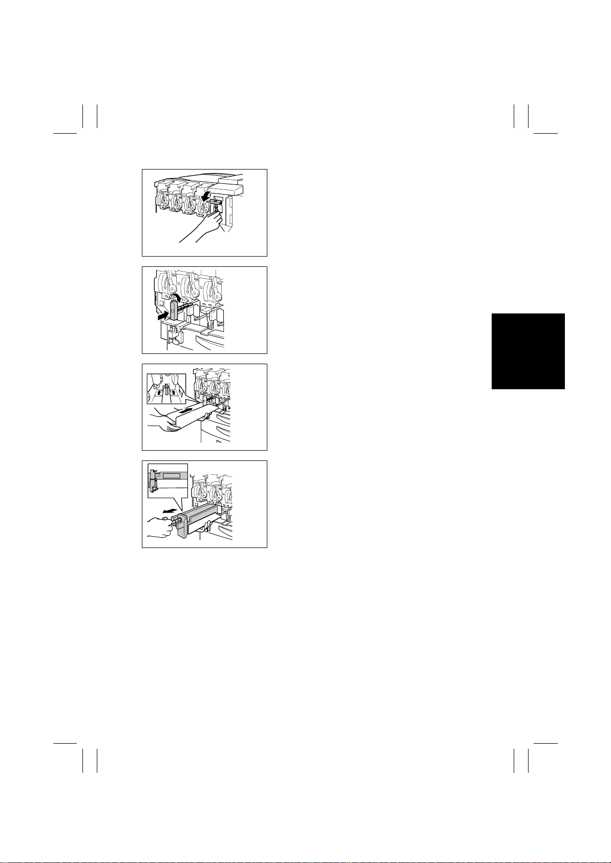
6. Remove the removal jig of the Imaging Unit from
the main unit.
C4587U004AA
7. Set the removal jig of the Imaging Unit in place.
8. Slowly rotate the jig clock-wise until it is fixed.
C4587U005AA
9. Position the Imaging Unit Pull-out Tray under the
Imaging Unit and insert it all the way into position.
C4587U007AA
C4587U008AA
10. Supporting the Imaging Unit Pull-out Tray with a
hand, hold the Imaging Unit Pull-out Jig and gently slide out the Imaging Unit. Then, place the
Imaging Unit on the floor.
11. Remove the Imaging Unit Pull-out Jig and return
it to the copier.
E-23
Page 26
FrameMaker Ver.5.5E(PC) 8020/8031 M AINTENANCE
02.08.19
Reinstallation Procedure
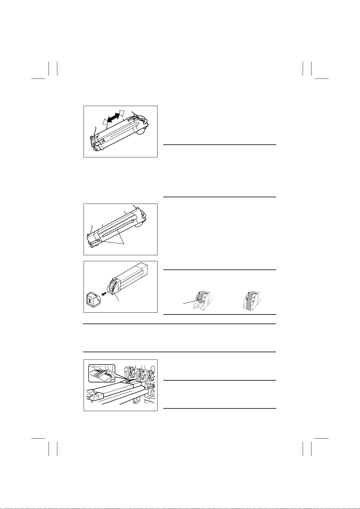
1. Remove the Imaging Unit from its aluminum
pack.
2. Tilt the Imaging Unit to the left and shake it a
small stroke in the tilt direction twice. Then, tilt it
to the right and shake it a small stroke in the tilt
direction twice.
C4587U013AA
4025U024AA
protective tape
protective sheet
C4587U015AB
NOTES
• Since the Imaging Unit is highly susceptible to
light, keep it in its aluminum pack up to the very
timing when it is installed.
• Carefully unseal the aluminum pack.
• If the Imaging Unit is packed in the aluminum pack
again, complete the seal the pack using tape or
other means.
3. Remove the protective tapes
4. Remove the shipping cushion.
CAUTION
• Make sure that the protectiv e sheet is rolled up into
the Imaging Unit as shown in the <OK>.
<OK> <NG>
protective
sheet
NOTE
• When installing the Imaging Unit, ensure that the color of the mounting guide of the
Imaging Unit is the same as the color of the label at the mounting position on the main
unit.
5. Keeping the Imaging Unit in a level position,
insert the Imaging Unit into the mounting position
all the way until it is stopped.
NOTE
• Do not allow the Imaging Unit to be tilted when
inserted, as a damaged PC Drum or LED Assy
4025U028AC
could result.
E-24
Page 27
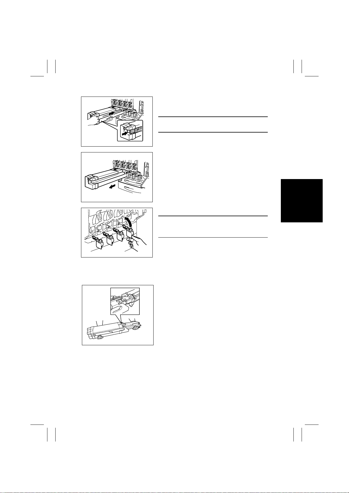
FrameMaker Ver.5.5E(PC) 8020/8031 M AINTENANCE
02.08.19
6. Holding the underside of the Imaging Unit with
your left hand, gently insert the Imaging Unit with
your right hand.
NOTE
• Insert the Imaging Unit until a click is heard.
4025U029AB
7. Remove the Imaging Unit Cover.
8. Check that the Imaging Unit has been inserted all
the way in the copier.
4025U030AB
9. Lock the IU Lock Lever.
NOTE
• Place the IU Lock Lever into the locked position
until a click is heard.
4025E040AA
10. Close the Front Door.
11. Place the empty Imaging Unit Cover on the floor.
12. Take out a pair of gloves from the packing box and wear it.
13. Insert the Imaging Unit which has been removed
into the Imaging Unit Cover .
C4587U024AA
14. Place the Imaging Unit that has been inserted into the Imaging Unit Cover in the aluminum pack and place the pack in the packing box.
15. Place the Imaging Unit Pull-out Tray, gloves, and packing material in the packing box .
16. Plug in the power cord.
17. Turn ON the Power Switch.
→
18. Select “Tech. Rep. Mode”
“Gradation Adjust” and carry out Gradation Adjust.
E-25
Page 28
FrameMaker Ver.5.5E(PC) 8020/8031 M AINTENANCE
02.08.19
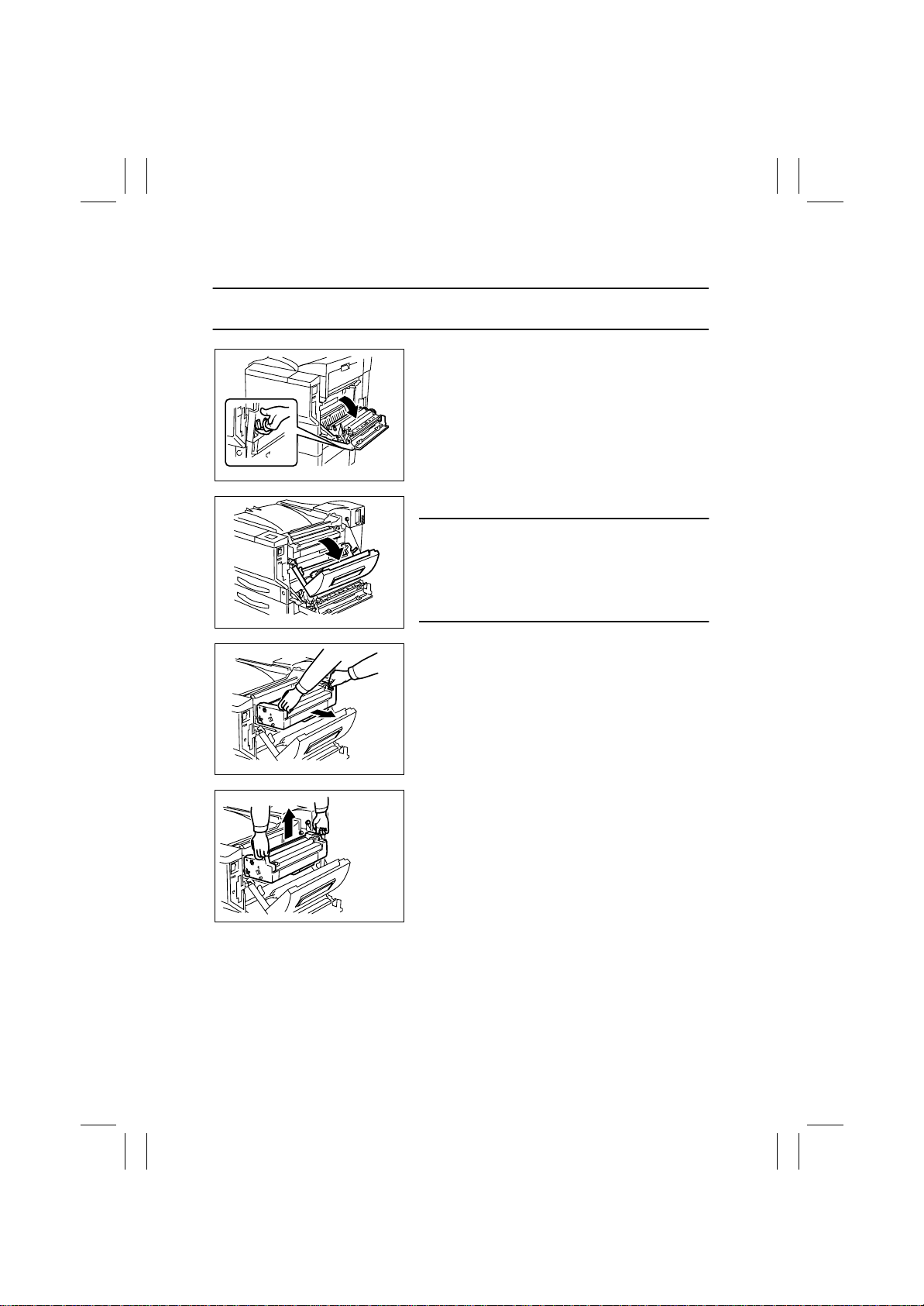
(4) Replacing the Fusing Unit
Removal Procedure
NOTE
• Before replacing the Fusing Unit, ensure that it is not hot.
1. Turn OFF the main switch, then wait for about 20
minutes.
2. Open the Right Door.
4025E018AA
3. Open the Upper Right Door.
NOTE
• When opening the Upper Right Door, be sure to
support it with your hand until it is in the fully open
position. If you remove your hand from the Upper
Right Door, it may drop, and the resulting impact
4025E041AA
may cause the hinges to bend.
4025E042AB
4025E043AA
4. Hold the handles (at two places) and slide out the
Fusing Unit.
5. Hold the handles (at two places) and remove the
Fusing Unit.
E-26
Page 29
FrameMaker Ver.5.5E(PC) 8020/8031 M AINTENANCE
02.08.19
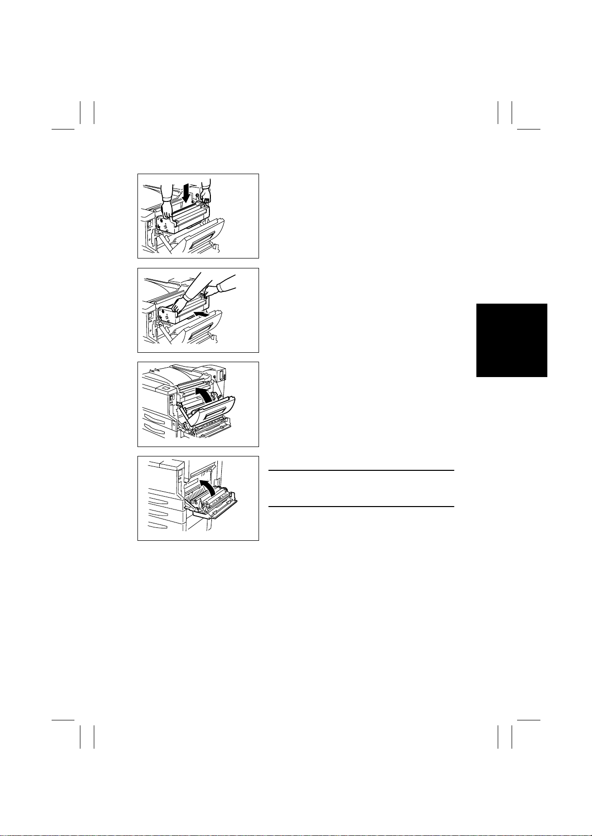
Reinstallation Procedure
1. Hold the handles (at two places) and place the
Fusing Unit in position.
4025E044AA
2. Hold the handles (at two places) and push the
Fusing Unit into position.
4025E044AB
3. Close the Upper Right Door.
4025E046AA
4025E021AA
4. Close the Right Door.
NOTE
• Ensure that both the front and rear sides are
locked.
E-27
Page 30

FrameMaker Ver.5.5E(PC) 8020/8031 M AINTENANCE
02.08.19
Blank page
E-28
 Loading...