

Page 1
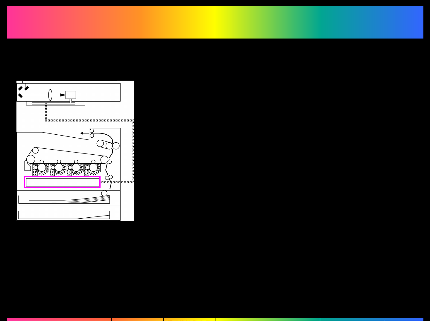
4.
4.
PIC Section
PIC Section
PIC: Print Image Control
1. LED Print Head (LPH)
2. LED Gradation Reproduction System
3. Outline of the PIC Section
4. PIC Image Processing Flow
5. Color Shift Correction System
Page 2
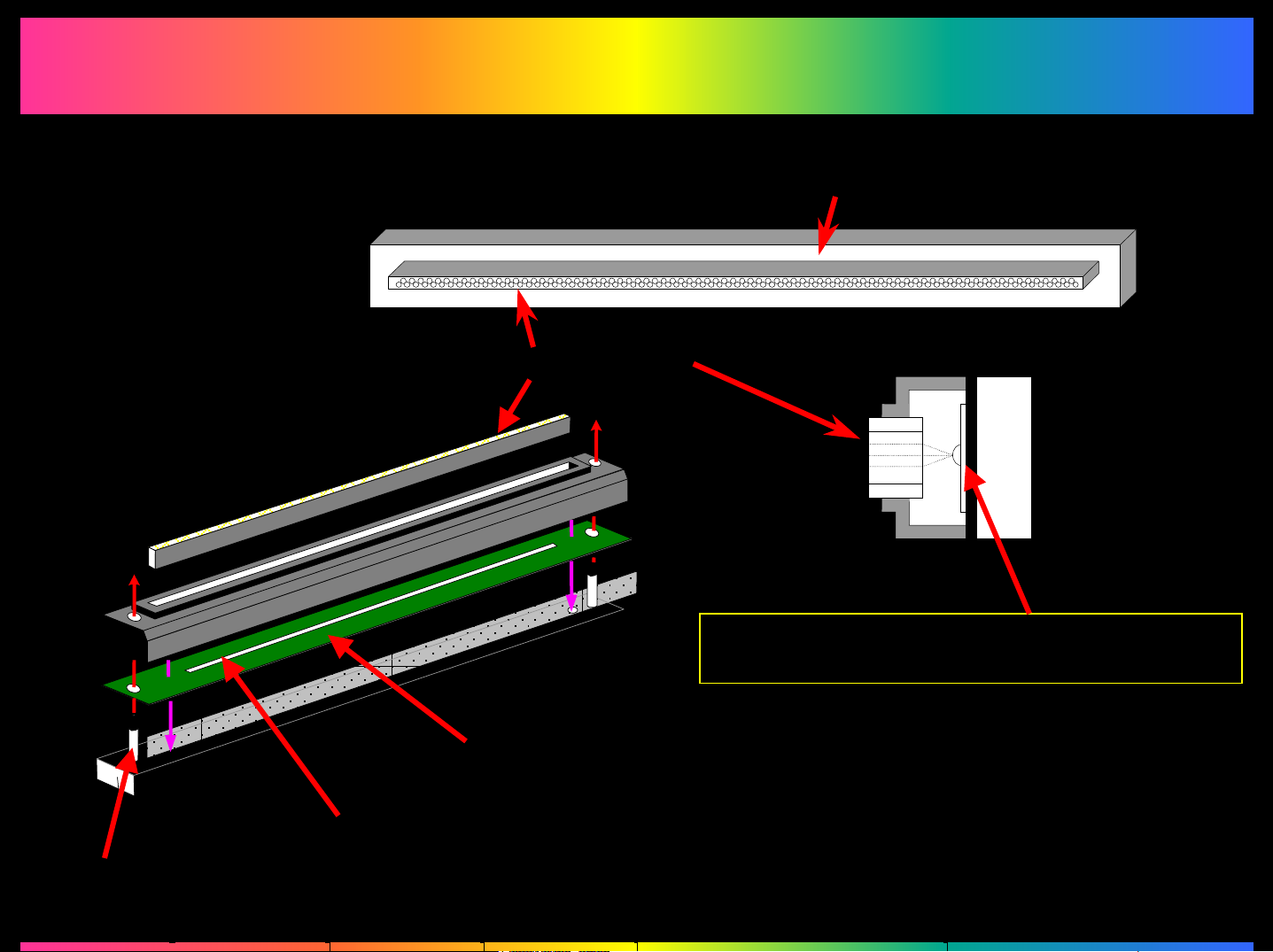
4.1
4.1
LED
LED
Print Head (LPH)
Print Head (LPH)
Perspective View
SLA (SELFOC Lens Array)
LED Unit
Side View
LED Chip
(600 dpi = approx. 7,700 chips)
Positioning Pin
Circuit Board
LED Chip
Page 3

4.1.1
4.1.1
(Similar to 7920)
Features
Features
of LED
of LED
Print Head
Print Head
Advantages
• The Optical System is designed compact.
• It is easier to achieve the goal of high-speed printing.
• The body is more resistant to deformation under changing environmental conditions.
• It is easier to make optical adjustments (optical path, optical axis, etc.).
Required New Technology (To increase LPH Efficiency)
• Intensity correction technology that makes the intensity of all light emitting bodies
uniform.
• Gradation reproduction technology that produces no uneven intensities on the image.
• Registration and Skew Correction technology that corrects any distortion in the LED
itself.
Page 4
4.2
4.2
(Common with the 7920 System)
Direction
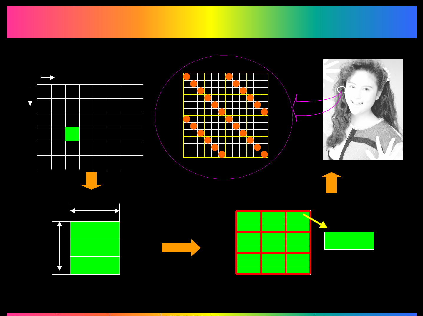
LED Gradation Reproduction System
LED Gradation Reproduction System
Main Scanning Direction
Sub-Scanning
Screen
Sample
42.3 µ m
42.3 µ m
4bit
4bit
3 pixels X 3 pixels
4bit
48 gradation levels per 1 pixel (4bit X 3) < 256 gradation levels
4bit
432 gradation levels
(48 X 9) > 256
gradation levels
Page 5
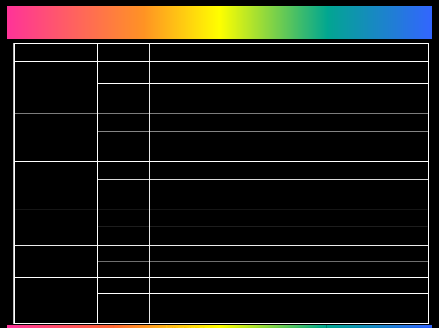
4.2.1 Screen Patterns
4.2.1 Screen Patterns
Specific Processing Performed & Screen PatternSectionOriginal Mode
Black text discrimination + Dot discriminationReading Text & Photo
Writing
Writing
Writing
FEET + Screen optimized for resolution or
Screen optimized for gradation
Black text discrimination + Dot discriminationReadingPhoto Image
Screen optimized for gradation or
Screen optimized for resolution
SmoothingReadingPrinted Image
Screen optimized for gradation or
Screen optimized for resolution
Black text discrimination + Dot discriminationReadingText
FEET + Screen optimized for resolutionWriting
Black text discrimination + Dot discriminationReadingMap
Writing
FEET + Screen for Map modeWriting
Black text discrimination + Dot discriminationReadingCopied Image
FEET + Screen optimized for resolution or
Screen optimized for gradation
Page 6
4.3
4.3
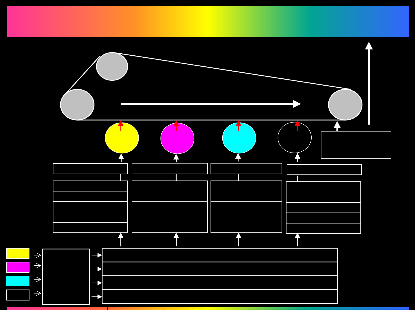
Transfer
Belt
Outline of the PIC Section
Outline of the PIC Section
Image Transfer
2nd Image
Transfer
Section
Y
PC Drum
LED Exposure Unit
LED Drive
Screen Control
Gamma Correction
GBTC Expansion
Color Shift Correction
GBTC
Y
Sequence
M
LED Exposure Unit LED Exposure Unit
LED Drive LED Drive
Screen Control Screen Control
Gamma Correction Gamma Correction
GBTC Expansion GBTC Expansion
Color Shift Correction Color Shift Correction
C Bk
Frame Memory
Paper
Path
Registration
Sensor
LED Exposure Unit
LED Drive
Screen Control
Gamma Correction
GBTC Expansion
Color Shift Correction
M
C
Bk
Compression
Frame Memory
Frame Memory
Frame Memory
Page 7
4.4
4.4
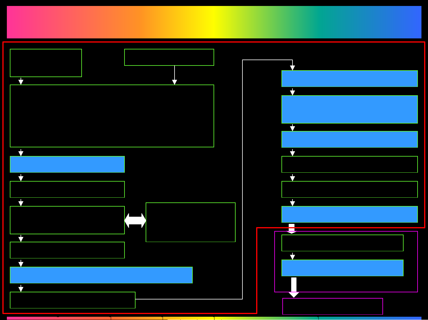
PIC Image Processing Flow
PIC Image Processing Flow
2. Color Correction1. Image Area
Discrimination
3. Miscellaneous Processing:
Improved reproduction of black text, edge
emphasis, edge expansion, smoothing, color
balance, γ correction, ACS Processing, and
AE Processing
5. Input Buffer Memory
6. Memory Access
Coordinator
7. Frame Memory
192 MB
PIC Board
11. GBTC Expansion
12. 1,800-dpi Color
Shift/Skew Correction
13. Area Discrimination FEET
14. Interpolation4. GBTC Compression
15. Gamma Correction
16. Screening
8. Output Buffer Memory
9. 600-dpi Color Shift/Skew Correction
10. CD Position Correction
17. High-Speed LED Drive
18. Intensity Correction
LED Board
To Each LED Unit
Page 8
4.4.1
4.4.1
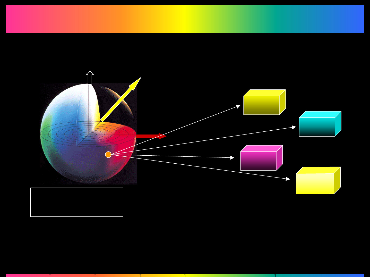
Color Correction (1)
Color Correction (1)
+L White
+b Yellow
+a Red
3D image of the
L*a*b* color space
This color conversion system uses a
positioning and selection operation to
determine where the RGB (L*a*b*)
colors will be placed in each of the
CMYK colors.
Page 9
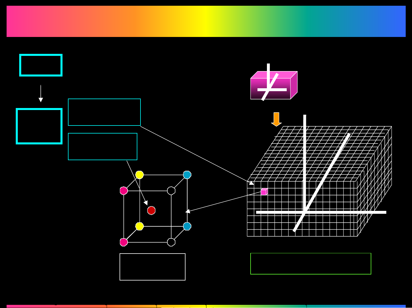
Color Correction (2)
Color Correction (2)
RGB
The most
significant bit
Most
significant bit
determines the
cube's position.
Lab
Least
significant bit
-a
+L
-b
+b
+a
The color space is
divided into
approx. 2,000 cube
positions.
+L
+b
The data of the eight
vertexes and the
least significant bit
of the input L*a*b*
data are interpolated
to calculate the
output of the CMYK
density data.
8-vertex
interpolation
Enlarged
view
-a
+a
-L
-b
3D Look-up Table
Page 10
4.4.2
4.4.2
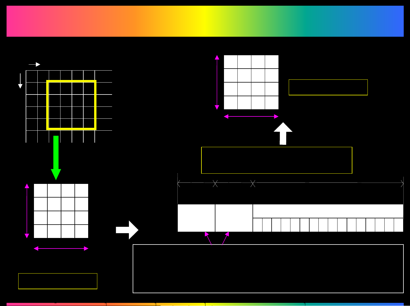
GBTC: General Block Truncation Coding
GBTC Compression/Expansion
GBTC Compression/Expansion
Sub-scanning direction
4dots
Main scanning direction
Image data is divided
Into a 4x4-dot section
D3D2D1D0
D8
Dc
D5D4
D9
Dd
D7D6
DbDa
DfDe
GBTC
Compression
4dot
8031: 8bit+ 8bit + 4×4×3bit =64bit
8020: 8bit+ 8bit + 4×4×1bit =32bit
8bit 8bit
LA LD
D8
Dc
D5D4
D9
Dd
4dot
D3D2D1D0
D7D6
DbDa
DfDe
0 1 2 3 4 5 6 7 8 9 a b c d e f
4×4×9bit =144bit
GBTC Expansion
8031: 16dots x 3bit
8020: 16dots x 1bit
∅
4dots
4×4×9bit =144bit
(1) Calculates the maximum and minimum gradation levels.
(2) Calculates the average data, gradation dynamic range,
and quantization reference.
(3) Quantizes each pixel to 1 bit (8020) or 3Bits (8031).
Page 11
4.4.3
4.4.3
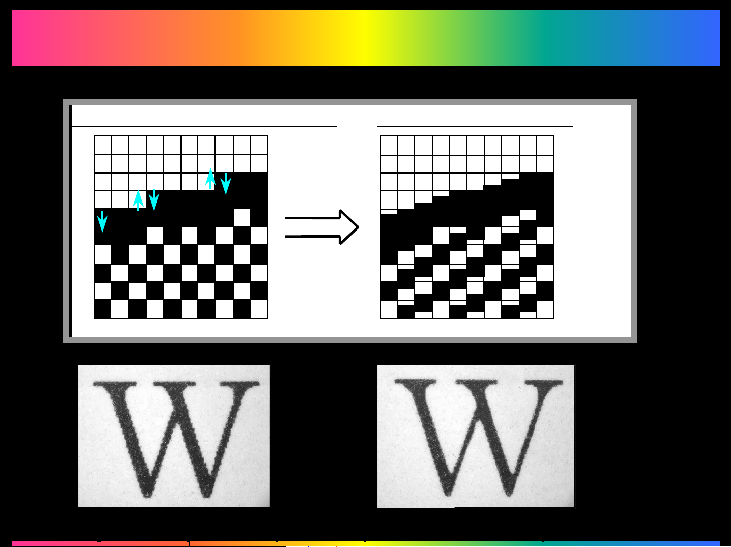
FEET: Fine Edge Enhanced Technology
FEET Processing
FEET Processing
Conventional Image Reproduction New Image Reproduction
Page 12
4.4.4
4.4.4
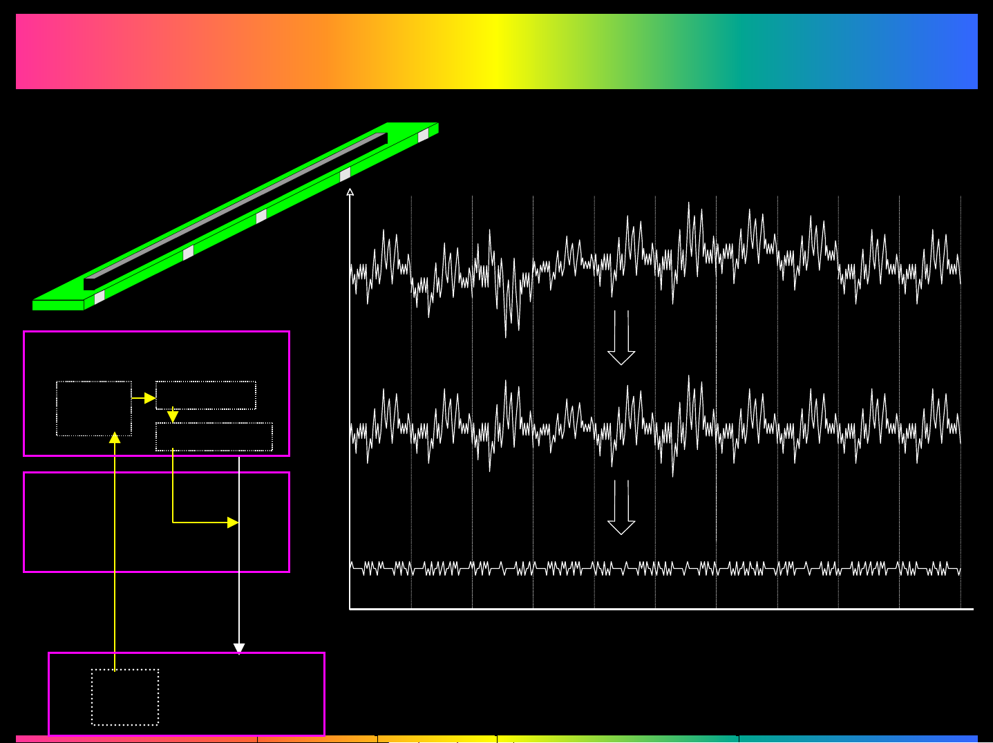
PIC Board
Intensity Correction
Intensity Correction
Chip Intensity Correction
Flash
ROM
LED
Drive
Board
Intensity
Correction
Data
EEP
ROM
CPU
ASIC
Image
Data
LPH
Assy.
LED Intensity
0
Dot Intensity Correction
Approx. 7,700
LED Pixel Position
Page 13
4.5
4.5
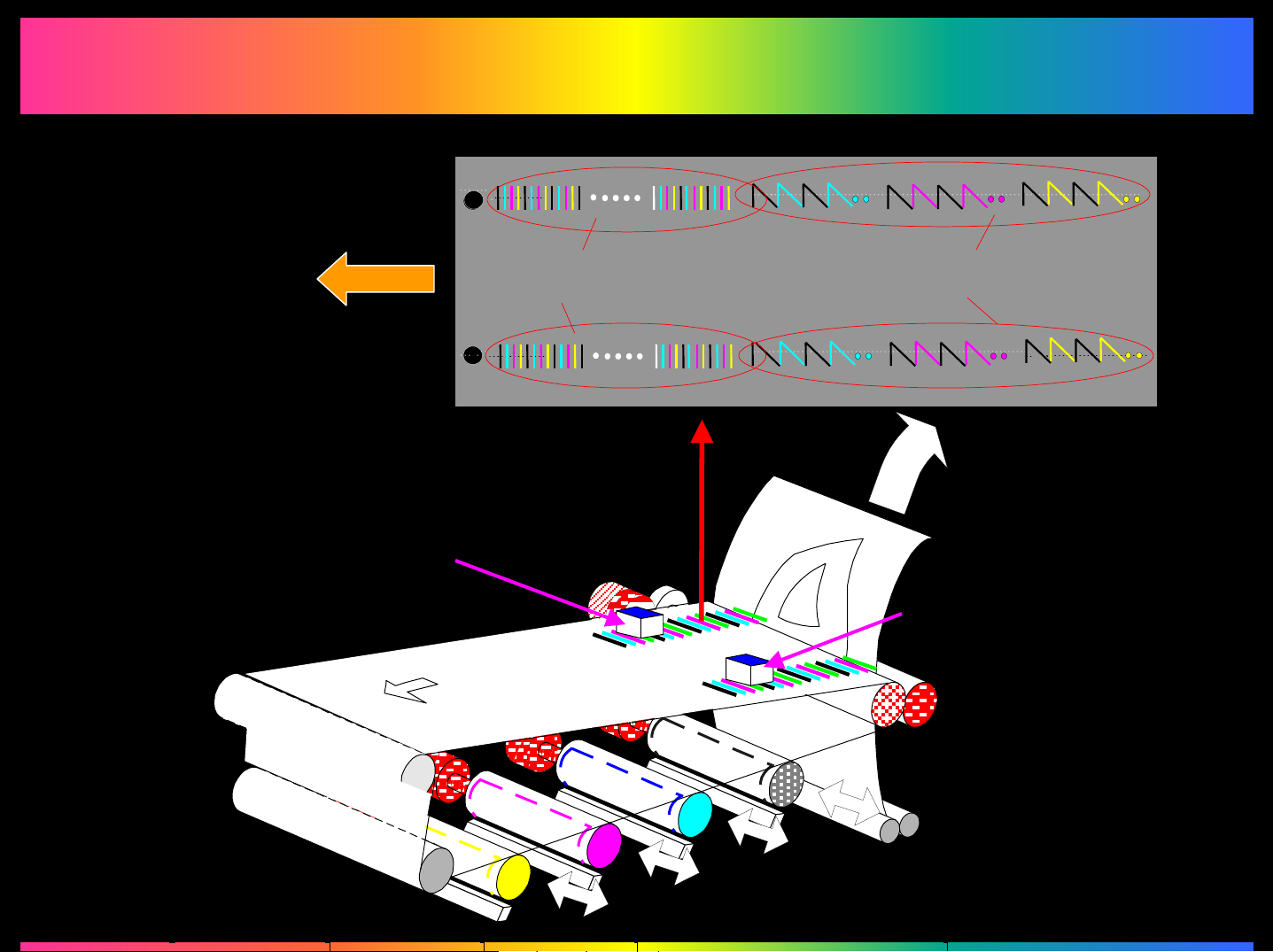
Outline of the
Color Shift Correction
Color Shift Correction System (1)
Color Shift Correction System (1)
feed
Rear Registration
Sensor
Detection Pattern for
Sub-Scanning Direction
Transfer Belt
Detection Pattern for
Main Scanning Direction
Front Registration
Sensor
Page 14
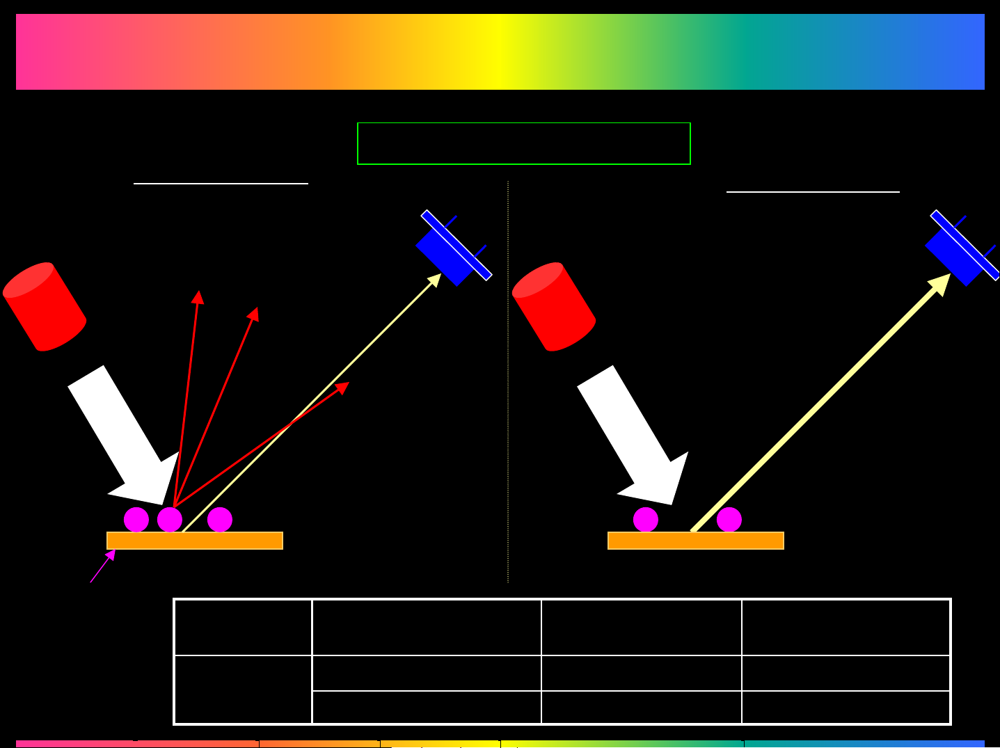
Color Shift Correction System (2)
Color Shift Correction System (2)
Construction of the Sensor
Amount of toner Attracted
LED
Large Amount
Small Amount
LED
Transfer Belt
Amount of toner
Attracted
OutputReflected Light
Intensity
LowLowLargeColor Toner
HighHighSmall
Page 15
4.5.1
4.5.1
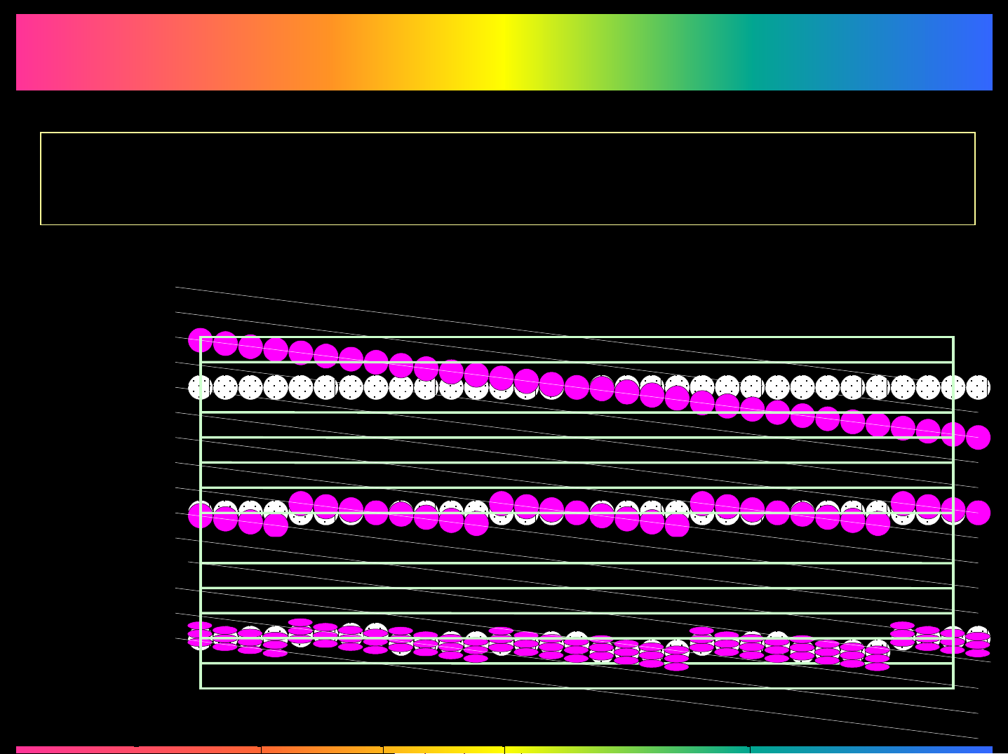
As the results of Color Shifting Detection, any skew in the Sub-Scanning direction is
corrected with reference to the black image. (The address of the pixels is controlled
over the different scanning directions)
Color Shift/
Skew
Skew
Color Shifting/Skew Correction
Color Shifting/Skew Correction
Correction
at 600dpi
Skew
Correction
at 1800dpi
Page 16
4.5.2
4.5.2
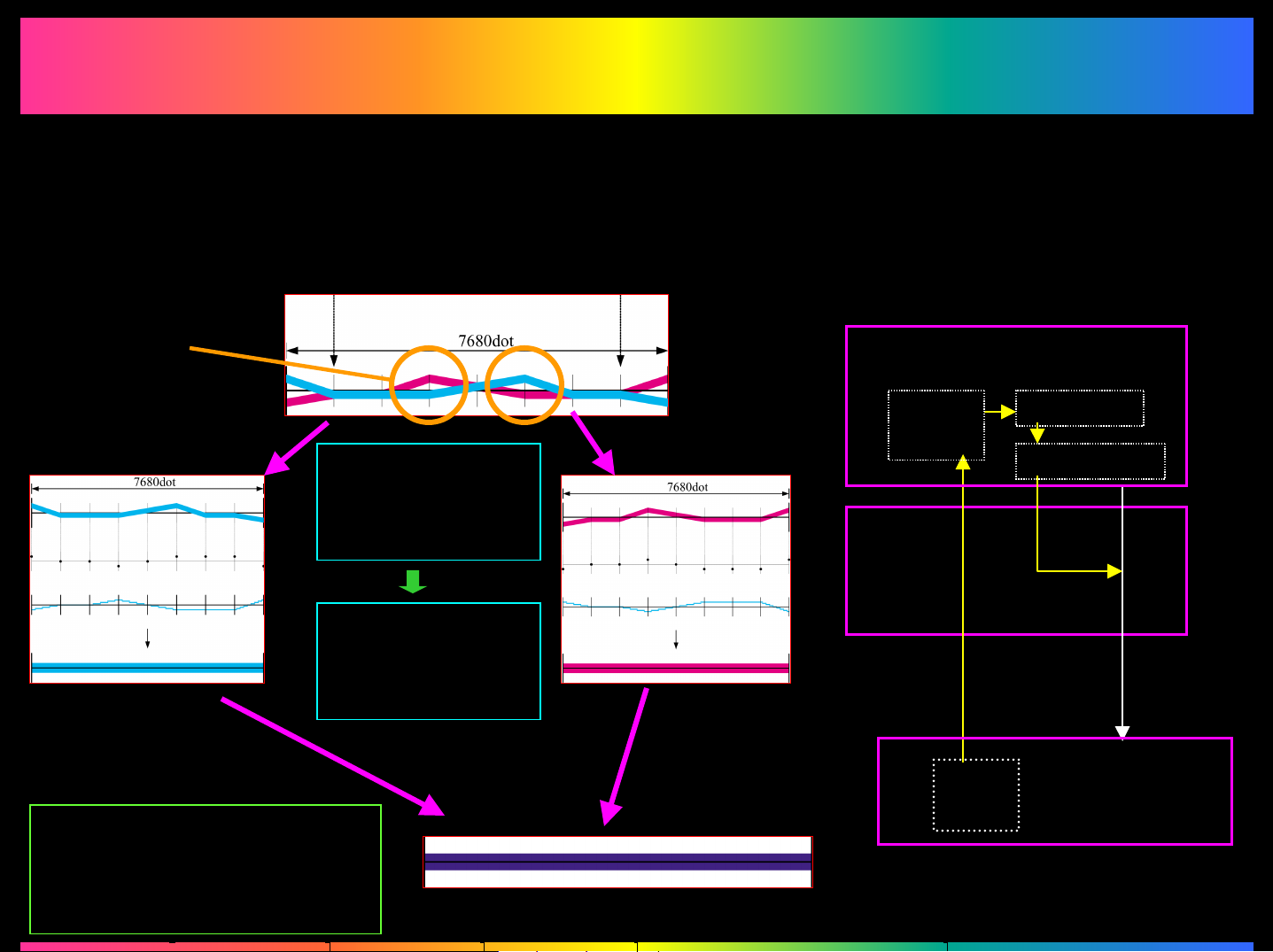
Color Shifting Sample: C & M
LPH Linearity Correction
LPH Linearity Correction
Position of the
Registration Sensor
Cause of
Color Shifting
Position of the
Registration Sensor
Result
measured at
120 points
Correction
Data is stored
in EEPROM
Correction Data
Flow
PIC Board
Flash
ROM
LED
Drive
Board
Intensity
Correction
Data
CPU
ASIC
Image
Data
Printing after
operating LPH
Linearity Correction
EEP
ROM
LPH
Assy.
Page 17
4.5.3
4.5.3
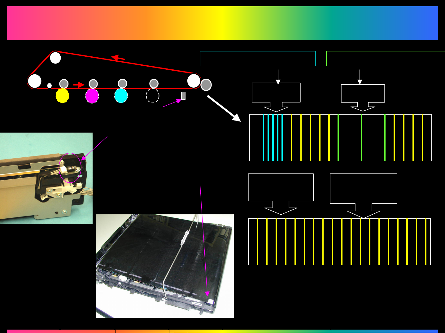
Correction of the Transfer Belt Rotation Speed
Correction of the Transfer Belt Rotation Speed
Transfer Belt Reference
Position Sensor
Reference Position
Mark for the Belt
Transfer Belt is thin
Slow Fast
Longer Exp.
Time
Transfer Belt is thick
Shorter Exp.
Time
Uniform (Divided into 224 portions)
 Loading...