


SERVICE MANUAL
Date: 2012/07/12

Table of Contents
Revision history......................................................................................................................................1
A SAFETY AND IMPORTANT WARNING ITEMS............................................................................A-1
1. IMPORTANT NOTICE.................................................................................................................................................A-2
2. DESCRIPTION ITEMS FOR DANGER, WARNING AND CAUTION..........................................................................A-3
2.1 Description items in this Service Manual...................................................................................................................................A-3
2.2 Description items for safety and important warning items.........................................................................................................A-3
3. SAFETY WARNINGS..................................................................................................................................................A-4
3.1 MODIFICATIONS NOT AUTHORIZED BY KONICA MINOLTA BUSINESS TECHNOLOGIES, INC......................................A-4
3.1.1 Actions requiring special attention...................................................................................................................................A-4
3.2 POWER PLUG SELECTION.....................................................................................................................................................A-5
3.2.1 Power Cord Set or Power Plug.......................................................................................................................................A-5
3.3 CHECKPOINTS WHEN PERFORMING ON-SITE SERVICE...................................................................................................A-6
3.3.1 Power Supply..................................................................................................................................................................A-7
3.3.2 Installation Requirements..............................................................................................................................................A-11
3.3.3 After Service..................................................................................................................................................................A-13
3.4 FUSE.......................................................................................................................................................................................A-18
3.5 Used Batteries Precautions.....................................................................................................................................................A-19
3.5.1 ALL Areas......................................................................................................................................................................A-19
3.5.2 Germany........................................................................................................................................................................A-19
3.5.3 France...........................................................................................................................................................................A-19
3.5.4 Denmark........................................................................................................................................................................A-19
3.5.5 Finland, Sweden............................................................................................................................................................A-19
3.5.6 Norway..........................................................................................................................................................................A-19
3.6 Laser Safety............................................................................................................................................................................A-20
3.6.1 Laser Safety..................................................................................................................................................................A-20
3.6.2 Internal Laser Radiation................................................................................................................................................A-20
3.6.3 Laser Safety Label........................................................................................................................................................A-24
3.6.4 Laser Caution Label......................................................................................................................................................A-24
3.6.5 PRECAUTIONS FOR HANDLING THE LASER EQUIPMENT.....................................................................................A-24
4. WARNING INDICATIONS ON THE MACHINE.........................................................................................................A-26
4.1 Warning indications inside the machine..................................................................................................................................A-26
4.2 Warning indications on the boards..........................................................................................................................................A-27
5. MEASURES TO TAKE IN CASE OF AN ACCIDENT...............................................................................................A-28
B NOTATION OF THE CONTENTS..................................................................................................B-1
1. NOTATION OF THE CONTENTS...............................................................................................................................B-1
1.1 Product name............................................................................................................................................................................B-1
1.2 Brand name...............................................................................................................................................................................B-1
1.3 Paper feed direction..................................................................................................................................................................B-1
C PRODUCT SPECIFICATIONS......................................................................................................C-1
1. bizhub 235/215/195.....................................................................................................................................................C-1
1.1 Type..........................................................................................................................................................................................C-1
1.2 Functions...................................................................................................................................................................................C-1
1.3 Paper.........................................................................................................................................................................................C-2
1.4 Materials....................................................................................................................................................................................C-2
1.5 Print volume..............................................................................................................................................................................C-2
1.5.1 bizhub 215.......................................................................................................................................................................C-2
1.5.2 bizhub 195.......................................................................................................................................................................C-2
1.6 Machine specifications..............................................................................................................................................................C-2
1.7 Operating environment..............................................................................................................................................................C-3
1.8 Print function.............................................................................................................................................................................C-3
1.9 Scan function.............................................................................................................................................................................C-3
2. AD-509........................................................................................................................................................................C-4
2.1 Type..........................................................................................................................................................................................C-4
2.2 Paper type.................................................................................................................................................................................C-4
2.3 Machine specifications..............................................................................................................................................................C-4
2.4 Operating environment..............................................................................................................................................................C-4
3. DF-625........................................................................................................................................................................C-5
3.1 Type..........................................................................................................................................................................................C-5
3.2 Functions...................................................................................................................................................................................C-5
3.3 Paper type.................................................................................................................................................................................C-5
3.4 Paper feed prohibited originals..................................................................................................................................................C-5
3.5 Paper feed not guaranteed originals.........................................................................................................................................C-5
3.6 Mixed original feed chart...........................................................................................................................................................C-6
i

3.7 Machine specifications..............................................................................................................................................................C-6
3.8 Operating...................................................................................................................................................................................C-6
4. MB-505........................................................................................................................................................................C-7
4.1 Paper.........................................................................................................................................................................................C-7
4.2 Machine specifications..............................................................................................................................................................C-7
4.3 Operating environment..............................................................................................................................................................C-7
5. PF-507........................................................................................................................................................................C-8
5.1 Type..........................................................................................................................................................................................C-8
5.2 Paper type.................................................................................................................................................................................C-8
5.3 Machine specifications..............................................................................................................................................................C-8
5.4 Operating environment..............................................................................................................................................................C-8
6. FK-510........................................................................................................................................................................C-9
D OVERALL COMPOSITION............................................................................................................D-1
1. SYSTEM CONFIGURATION......................................................................................................................................D-1
2. CROSS SECTIONAL VIEW........................................................................................................................................D-2
3. PAPER PATH.............................................................................................................................................................D-3
4. OVERALL CONFIGRATION.......................................................................................................................................D-4
4.1 Control Block Diagram..............................................................................................................................................................D-4
4.2 Image creation process ............................................................................................................................................................D-4
E SERVICE TOOL.............................................................................................................................E-1
1. Service material list.....................................................................................................................................................E-1
2. CE tool list...................................................................................................................................................................E-2
F MAINTENANCE..............................................................................................................................F-1
1. Concept of periodical maintenance.............................................................................................................................F-1
1.1 Concept of periodical maintenance...........................................................................................................................................F-1
1.2 bizhub 235/215/195...................................................................................................................................................................F-1
1.2.1 Periodical maintenance 1 (Total counter; every 55,000 counts).....................................................................................F-1
1.2.2 Periodical maintenance 2 (PM counter; every 165,000 counts)......................................................................................F-1
1.2.3 Periodical maintenance 3 (SUPPLIES counter; every 165,000 counts)..........................................................................F-1
1.3 Option........................................................................................................................................................................................F-1
1.3.1 Reverse automatic document feeder (DF-625)...............................................................................................................F-1
1.3.2 Paper feeder unit (PF-507)..............................................................................................................................................F-1
1.3.3 Multi bypass tray (MB-505)..............................................................................................................................................F-2
2. PERIODICAL MAINTENANCE ITEMS........................................................................................................................F-3
2.1 Periodical replacement parts list................................................................................................................................................F-3
2.1.1 Periodical replacement parts list......................................................................................................................................F-3
2.1.2 bizhub 235/215/195.........................................................................................................................................................F-3
2.1.3 Option..............................................................................................................................................................................F-3
2.2 Periodical cleaning parts list......................................................................................................................................................F-3
2.2.1 bizhub 235/215/195.........................................................................................................................................................F-3
2.2.2 Option..............................................................................................................................................................................F-4
2.3 Concept of parts life...................................................................................................................................................................F-4
2.3.1 Life value of consumables and parts...............................................................................................................................F-4
2.3.2 Conditions for life specifications values...........................................................................................................................F-4
3. PERIODICAL MAINTENANCE PROCEDURE bizhub 235/215/195...........................................................................F-5
3.1 Processing section.....................................................................................................................................................................F-5
3.1.1 Replacing the developer..................................................................................................................................................F-5
3.1.2 Replacing the drum.........................................................................................................................................................F-7
3.1.3 Replacing the drum charge corona assy.........................................................................................................................F-8
3.1.4 Replacing the cleaning blade..........................................................................................................................................F-9
3.1.5 Application of toner..........................................................................................................................................................F-9
3.1.6 Replacing the toner bottle..............................................................................................................................................F-10
3.1.7 Cleaning of the Ds collars..............................................................................................................................................F-11
3.1.8 Cleaning of the drum separator fingers.........................................................................................................................F-12
3.1.9 Cleaning of the developer scattering prevention plate..................................................................................................F-12
3.1.10 Replacing the imaging unit..........................................................................................................................................F-14
3.2 Conveyance section................................................................................................................................................................F-14
3.2.1 Cleaning of the registration roller...................................................................................................................................F-14
3.2.2 Cleaning of the pre-image transfer guide plate.............................................................................................................F-14
3.3 Fusing section..........................................................................................................................................................................F-16
3.3.1 Replacing the fusing unit...............................................................................................................................................F-16
3.4 Paper feed section...................................................................................................................................................................F-17
3.4.1 Replacing the tray 1 feed roller......................................................................................................................................F-17
3.4.2 Replacing the tray 1 separation pad..............................................................................................................................F-18
3.5 Conveyance section................................................................................................................................................................F-18
ii

3.5.1 Replacing the transfer roller unit....................................................................................................................................F-18
4. PERIODICAL MAINTENANCE PROCEDURE DF-625.............................................................................................F-19
4.1 Paper feed section (DF-625)...................................................................................................................................................F-19
4.1.1 Replacing the separation roller (DF-625)......................................................................................................................F-19
4.1.2 Cleaning of the pick-up roller/feed roller/separation roller (DF-625)..............................................................................F-20
4.1.3 Cleaning of the document transport sensor (DF-625)...................................................................................................F-21
4.2 Conveyance section (DF-625).................................................................................................................................................F-21
4.2.1 Cleaning of the roller and rolls (DF-625).......................................................................................................................F-21
4.3 Scanning section (DF-625)......................................................................................................................................................F-22
4.3.1 Cleaning of the scanning guide (DF-625)......................................................................................................................F-22
5. PERIODICAL MAINTENANCE PROCEDURE PF-507.............................................................................................F-24
5.1 Paper feed section (PF-507)....................................................................................................................................................F-24
5.1.1 Replacing the feed roller (PF-507)................................................................................................................................F-24
6. PERIODICAL MAINTENANCE PROCEDURE MB-505............................................................................................F-25
6.1 Paper feed section (MB-505)...................................................................................................................................................F-25
6.1.1 Replacing the feed roller (MB-505)................................................................................................................................F-25
6.1.2 Replacing the separation roller assy (MB-505).............................................................................................................F-26
G DISASSEMBLING/REASSEMBLING............................................................................................G-1
1. Disassembly/adjustment prohibited items...................................................................................................................G-1
1.1 Disassembly/adjustment prohibited items.................................................................................................................................G-1
1.1.1 Paint-locked screws........................................................................................................................................................G-1
1.1.2 Red-painted screws........................................................................................................................................................G-1
1.1.3 Variable resistors on board.............................................................................................................................................G-1
1.1.4 Removal of PWBs...........................................................................................................................................................G-1
1.1.5 Warnings for disassembly...............................................................................................................................................G-2
1.1.6 Precautions/warnings during setup or transportation......................................................................................................G-2
1.2 Units from which removing is prohibited...................................................................................................................................G-3
1.2.1 PH unit............................................................................................................................................................................G-3
1.2.2 Fusing unit......................................................................................................................................................................G-3
2. bizhub 235/215/195....................................................................................................................................................G-4
2.1 Disassembly/reassembly parts list............................................................................................................................................G-4
2.1.1 Exterior parts...................................................................................................................................................................G-4
2.1.2 Units................................................................................................................................................................................G-4
2.1.3 Boards.............................................................................................................................................................................G-4
2.1.4 Others.............................................................................................................................................................................G-4
2.2 Disassembly/reassembly procedure (Exterior parts)................................................................................................................G-4
2.2.1 Front door.......................................................................................................................................................................G-4
2.2.2 Front cover......................................................................................................................................................................G-5
2.2.3 Left cover........................................................................................................................................................................G-5
2.2.4 Right rear cover..............................................................................................................................................................G-5
2.2.5 Right lower cover............................................................................................................................................................G-6
2.2.6 Rear cover......................................................................................................................................................................G-6
2.2.7 Scanner right cover.........................................................................................................................................................G-6
2.2.8 Paper exit rear cover.......................................................................................................................................................G-6
2.2.9 Paper exit tray (left) / Paper exit tray (right)....................................................................................................................G-7
2.2.10 Control panel left cover.................................................................................................................................................G-7
2.2.11 Control panel.................................................................................................................................................................G-7
2.2.12 Original glass assy........................................................................................................................................................G-8
2.3 Disassembly/reassembly procedure (Units)..............................................................................................................................G-9
2.3.1 Tray 1..............................................................................................................................................................................G-9
2.3.2 PH unit..........................................................................................................................................................................G-10
2.3.3 CIS module (CIS)..........................................................................................................................................................G-11
2.3.4 Scanner unit..................................................................................................................................................................G-12
2.3.5 Paper exit unit...............................................................................................................................................................G-13
2.4 Disassembly/reassembly procedure (Boards)........................................................................................................................G-14
2.4.1 MFP board (MFPB).......................................................................................................................................................G-14
2.4.2 High voltage unit (HV1).................................................................................................................................................G-15
2.4.3 DC power supply (DCPU).............................................................................................................................................G-15
2.4.4 BB Module board (BBMB).............................................................................................................................................G-16
2.5 Disassembly/reassembly procedure (Others).........................................................................................................................G-16
2.5.1 Ozone filter....................................................................................................................................................................G-16
2.5.2 Main motor (M1)............................................................................................................................................................G-16
2.5.3 Toner supply motor (M2)...............................................................................................................................................G-17
2.5.4 Scanner motor (M3)......................................................................................................................................................G-17
2.5.5 Switchback motor (M4).................................................................................................................................................G-18
2.5.6 Fusing cooling fan motor (FM1)....................................................................................................................................G-19
2.5.7 Registration clutch (CL1)..............................................................................................................................................G-19
2.5.8 Tray1 paper feed clutch (CL2)......................................................................................................................................G-19
iii

2.5.9 Temperature/humidity sensor (TEM/HUM)...................................................................................................................G-20
2.5.10 Inch/metric sensor (PS6) assy (Asia Pacific only)......................................................................................................G-20
3. Option.......................................................................................................................................................................G-22
3.1 Disassembly/reassembly parts list..........................................................................................................................................G-22
3.1.1 DF-625..........................................................................................................................................................................G-22
3.1.2 PF-507..........................................................................................................................................................................G-22
3.1.3 MB-505.........................................................................................................................................................................G-22
3.1.4 AD-509..........................................................................................................................................................................G-22
3.1.5 FK-510..........................................................................................................................................................................G-22
3.1.6 IC-209/NC-504..............................................................................................................................................................G-22
3.1.7 MC-504.........................................................................................................................................................................G-22
3.2 Disassembly/reassembly procedure(DF-625).........................................................................................................................G-23
3.2.1 Upper cover (DF-625)...................................................................................................................................................G-23
3.2.2 Front cover (DF-625)....................................................................................................................................................G-23
3.2.3 Rear cover (DF-625).....................................................................................................................................................G-24
3.2.4 Original paper set tray (DF-625)...................................................................................................................................G-24
3.2.5 Reverse Automatic Document Feeder (DF-625)..........................................................................................................G-25
3.2.6 Upper door assy (DF-625)............................................................................................................................................G-26
3.2.7 Document conveyance unit (DF-625)...........................................................................................................................G-27
3.2.8 DF control board (DFCB) (DF-625)...............................................................................................................................G-28
3.2.9 Feed roller/Pick-up roller (DF-625)...............................................................................................................................G-28
3.2.10 DF motor (M1) (DF-625).............................................................................................................................................G-29
3.2.11 Document feed clutch (CL1) (DF-625)........................................................................................................................G-30
3.2.12 Document registration clutch (CL2) (DF-625).............................................................................................................G-30
3.2.13 Switchback clutch (CL3) (DF-625)..............................................................................................................................G-30
3.3 Disassembly/reassembly procedure (PF-507)........................................................................................................................G-31
3.3.1 Tray (PF-507)................................................................................................................................................................G-31
3.3.2 Rear cover (PF-507).....................................................................................................................................................G-31
3.3.3 Paper Feeder Unit (PF-507).........................................................................................................................................G-32
3.3.4 PF drive board (PFDB) (PF-507)..................................................................................................................................G-34
3.3.5 Paper size detect switch (S1) (PF-507)........................................................................................................................G-34
3.3.6 Paper feed solenoid (SD1) (PF-507)............................................................................................................................G-35
3.4 Disassembly/reassembly procedure (MB-505).......................................................................................................................G-36
3.4.1 Multi Bypass Tray (MB-505).........................................................................................................................................G-36
3.4.2 Bypass paper feed clutch (CL1) (MB-505)....................................................................................................................G-36
3.4.3 Bypass pick-up solenoid (SD1) (MB-505).....................................................................................................................G-37
3.5 Disassembly/reassembly procedure (AD-509)........................................................................................................................G-38
3.5.1 Right cover (AD-509)....................................................................................................................................................G-38
3.5.2 Automatic Duplex Unit (AD-509)...................................................................................................................................G-38
3.5.3 AD drive board (ADDB) (AD-509).................................................................................................................................G-39
3.5.4 AD motor (M1) (AD-509)...............................................................................................................................................G-39
3.5.5 Cooling fan motor (FM2) (AD-509)...............................................................................................................................G-39
3.6 Disassembly/reassembly procedure (FK-510)........................................................................................................................G-40
3.6.1 FAX board (FAXB) (FK-510).........................................................................................................................................G-40
3.6.2 FAX control panel (FK-510)..........................................................................................................................................G-40
3.6.3 Speaker (FK-510).........................................................................................................................................................G-40
3.7 Disassembly/reassembly procedure (IC-209/NC-504)............................................................................................................G-41
3.7.1 PCL/NIC board (PNICB)/NIC board (NICB) (IC-209/NC-504)......................................................................................G-41
3.8 Disassembly/reassembly procedure (MC-504).......................................................................................................................G-41
3.8.1 Mechanical Counter (MC-504)......................................................................................................................................G-41
H CLEANING/LUBRICATION...........................................................................................................H-1
1. bizhub235/215/195......................................................................................................................................................H-1
1.1 Cleaning parts list......................................................................................................................................................................H-1
1.2 Cleaning procedure...................................................................................................................................................................H-1
1.2.1 Tray 1 feed roller.............................................................................................................................................................H-1
1.2.2 Tray 1 separation pad.....................................................................................................................................................H-1
1.2.3 Original glass .................................................................................................................................................................H-1
2. Option..........................................................................................................................................................................H-2
2.1 Cleaning parts list......................................................................................................................................................................H-2
2.1.1 PF-507............................................................................................................................................................................H-2
2.1.2 AD-509............................................................................................................................................................................H-2
2.1.3 MB-505............................................................................................................................................................................H-2
2.2 Cleaning procedure (PF-507)....................................................................................................................................................H-2
2.2.1 Feed roller.......................................................................................................................................................................H-2
2.2.2 Vertical transport roller/roll..............................................................................................................................................H-2
2.3 Cleaning procedure (AD-509)...................................................................................................................................................H-2
2.3.1 Automatic duplex unit transport roller/roll........................................................................................................................H-2
2.3.2 Switchback section transport roller/roll............................................................................................................................H-3
2.3.3 Automatic duplex unit ventilation section........................................................................................................................H-3
iv

2.4 Cleaning procedure (MB-505)...................................................................................................................................................H-3
2.4.1 Separation roller..............................................................................................................................................................H-3
2.4.2 Feed roller.......................................................................................................................................................................H-4
I ADJUSTMENT/SETTING.................................................................................................................I-1
1. HOW TO USE THE ADJUSTMENT/SETTING SECTION............................................................................................I-1
1.1 Outline.........................................................................................................................................................................................I-1
1.2 Advance checks..........................................................................................................................................................................I-1
2. UTILITY MODE.............................................................................................................................................................I-2
2.1 List of utility mode.......................................................................................................................................................................I-2
2.2 Starting/Exiting............................................................................................................................................................................I-4
2.2.1 Starting procedure............................................................................................................................................................I-4
2.2.2 Exiting procedure..............................................................................................................................................................I-4
2.3 MACHINE SETTING...................................................................................................................................................................I-4
2.3.1 AUTO PANEL RESET......................................................................................................................................................I-4
2.3.2 SLEEP MODE..................................................................................................................................................................I-4
2.3.3 AUTO SHUT TIME...........................................................................................................................................................I-4
2.3.4 DENSITY (ADF)................................................................................................................................................................I-5
2.3.5 DENSITY (BOOK)............................................................................................................................................................I-5
2.3.6 PRINT DENSITY..............................................................................................................................................................I-5
2.3.7 LCD CONTRAST..............................................................................................................................................................I-5
2.3.8 KEY SPEED SETTING.....................................................................................................................................................I-5
2.3.9 LANGUAGE......................................................................................................................................................................I-6
2.3.10 BUZZER VOLUME.........................................................................................................................................................I-6
2.3.11 INITIAL MODE................................................................................................................................................................I-9
2.3.12 SCAN THRESHOLD.......................................................................................................................................................I-9
2.4 PAPER SOURCE SETUP........................................................................................................................................................I-10
2.4.1 TRAY1............................................................................................................................................................................I-10
2.4.2 TRAY2/TRAY3/TRAY4/TRAY5......................................................................................................................................I-10
2.5 CUSTOM SIZE MEMORY........................................................................................................................................................I-10
2.5.1 CUSTOME SIZE MEMORY............................................................................................................................................I-10
2.6 DRUM DEHUMIDIFY................................................................................................................................................................I-11
2.6.1 Use.................................................................................................................................................................................I-11
2.6.2 Step................................................................................................................................................................................I-11
2.7 ADMIN. MANAGEMENT...........................................................................................................................................................I-11
2.7.1 ADMINISTRATOR NO....................................................................................................................................................I-11
2.7.2 DISPLAY AUTO SHUT...................................................................................................................................................I-11
2.7.3 SLEEP SHIFT.................................................................................................................................................................I-11
2.7.4 ACCOUNT TRACK.........................................................................................................................................................I-11
2.7.5 REMOTE MONITOR......................................................................................................................................................I-12
2.7.6 NETWORK SETTING - IP ADDRESS SETTING...........................................................................................................I-13
2.7.7 NETWORK SETTING - IPv6..........................................................................................................................................I-14
2.7.8 NETWORK SETTING - DNS CONFIG...........................................................................................................................I-15
2.7.9 NETWORK SETTING - WEB SETTING.........................................................................................................................I-15
2.7.10 NETWORK SETTING - LPD SETTING........................................................................................................................I-15
2.7.11 NETWORK SETTING - SLP SETTING........................................................................................................................I-15
2.7.12 NETWORK SETTING - SNMP SETTING.....................................................................................................................I-15
2.7.13 NETWORK SETTING - AUTO GET TIME....................................................................................................................I-15
2.7.14 E-MAIL SETTING 1......................................................................................................................................................I-16
2.7.15 E-MAIL SETTING 2......................................................................................................................................................I-18
2.7.16 LDAP SETTING............................................................................................................................................................I-20
2.7.17 COMM. SETTING.........................................................................................................................................................I-22
2.7.18 USER SETTING...........................................................................................................................................................I-23
2.7.19 SCAN TO USB.............................................................................................................................................................I-24
2.8 COPY SETTING 1....................................................................................................................................................................I-24
2.8.1 PAPER PRIORITY..........................................................................................................................................................I-24
2.8.2 QUALITY PRIORITY......................................................................................................................................................I-24
2.8.3 DENSITY PRIORITY......................................................................................................................................................I-25
2.8.4 DENSITY LEVEL............................................................................................................................................................I-25
2.8.5 DUPLEX PRIORITY.......................................................................................................................................................I-25
2.8.6 OUTPUT BIND POS.......................................................................................................................................................I-25
2.8.7 ORIG.BINDING POS......................................................................................................................................................I-25
2.8.8 BINDING POSITION.......................................................................................................................................................I-26
2.8.9 MARGIN SETTING.........................................................................................................................................................I-26
2.8.10 ERASE SETTING.........................................................................................................................................................I-26
2.8.11 SMALL ORIGINAL........................................................................................................................................................I-26
2.9 COPY SETTING 2....................................................................................................................................................................I-26
2.9.1 COPY PRIORITY............................................................................................................................................................I-26
2.9.2 OUTPUT PRIORITY.......................................................................................................................................................I-27
2.9.3 CRISSCROSS MODE....................................................................................................................................................I-27
v

2.9.4 4IN1 COPY ORDER.......................................................................................................................................................I-27
2.9.5 MIXED ORIGINAL..........................................................................................................................................................I-27
2.9.6 ORIG. DIRECTION.........................................................................................................................................................I-27
2.9.7 BOOK SEPARATION.....................................................................................................................................................I-28
2.9.8 STAMP...........................................................................................................................................................................I-28
2.9.9 PAGE FORMAT..............................................................................................................................................................I-28
2.9.10 DATE & TIME FORMAT...............................................................................................................................................I-28
2.10 DIAL REGISTRATION............................................................................................................................................................I-28
2.10.1 ONE-TOUCH DIAL.......................................................................................................................................................I-28
2.10.2 SPEED DIAL.................................................................................................................................................................I-29
2.10.3 GROUP DIAL................................................................................................................................................................I-29
2.10.4 PROGRAM DIAL..........................................................................................................................................................I-29
2.11 FAX REGISTRATION.............................................................................................................................................................I-29
2.11.1 MAILBOX......................................................................................................................................................................I-29
2.11.2 RELAY BOX.................................................................................................................................................................I-30
2.12 FAX TX OPERATION.............................................................................................................................................................I-30
2.12.1 DENSITY LEVEL..........................................................................................................................................................I-30
2.12.2 QUALITY PRIORITY....................................................................................................................................................I-30
2.12.3 DEFAULT TX................................................................................................................................................................I-30
2.12.4 HEADER.......................................................................................................................................................................I-31
2.12.5 CONFIRM FAX NO.......................................................................................................................................................I-31
2.13 FAX RX OPERATION.............................................................................................................................................................I-31
2.13.1 MEMORY RX MODE....................................................................................................................................................I-31
2.13.2 NO. of RINGS...............................................................................................................................................................I-31
2.13.3 REDUCTION RX..........................................................................................................................................................I-31
2.13.4 RX PRINT.....................................................................................................................................................................I-38
2.13.5 RX MODE.....................................................................................................................................................................I-38
2.13.6 FORWARD...................................................................................................................................................................I-38
2.13.7 FOOTER.......................................................................................................................................................................I-38
2.13.8 SELECT TRAY.............................................................................................................................................................I-39
2.13.9 CLOSED NETWORK....................................................................................................................................................I-39
2.14 REPORTING...........................................................................................................................................................................I-39
2.14.1 ACTIVITY REPORT......................................................................................................................................................I-40
2.14.2 RESERVATION REPORT............................................................................................................................................I-40
2.14.3 TX RESULT REPORT..................................................................................................................................................I-40
2.14.4 RX RESULT REPORT..................................................................................................................................................I-40
2.15 SCAN SETTING.....................................................................................................................................................................I-40
2.15.1 RESOLUTION..............................................................................................................................................................I-40
2.15.2 IMAGE FORMAT..........................................................................................................................................................I-40
2.15.3 BW CODING METHOD................................................................................................................................................I-41
2.15.4 COLOR SETTING........................................................................................................................................................I-41
3. ADJUSTMENT ITEM LIST.........................................................................................................................................I-42
4. SERVICE MODE........................................................................................................................................................I-45
4.1 List of SERVICE MODE............................................................................................................................................................I-45
4.2 Starting/Exiting..........................................................................................................................................................................I-47
4.2.1 Starting procedure..........................................................................................................................................................I-47
4.2.2 Exiting procedure............................................................................................................................................................I-47
4.2.3 Changing the setting value in SERVICE MODE functions.............................................................................................I-47
4.3 SERVICE'S CHOICE................................................................................................................................................................I-47
4.3.1 MARKETING AREA........................................................................................................................................................I-47
4.3.2 SHIPMENT.....................................................................................................................................................................I-48
4.3.3 ENABLE AUTO SHUT....................................................................................................................................................I-48
4.3.4 MAINTENANCE COUNT................................................................................................................................................I-48
4.3.5 IU LIFE STOP MODE.....................................................................................................................................................I-48
4.3.6 ID ADJUST.....................................................................................................................................................................I-49
4.3.7 VG ADJUST....................................................................................................................................................................I-49
4.3.8 TRANSFER (PLAIN).......................................................................................................................................................I-49
4.3.9 TRANSFER (RECYCLE)................................................................................................................................................I-49
4.3.10 TRANSFER (CARD1)...................................................................................................................................................I-49
4.3.11 TRANSFER (CARD2)...................................................................................................................................................I-50
4.3.12 TRANSFER (OHP).......................................................................................................................................................I-50
4.3.13 TRANSFER (ENV.).......................................................................................................................................................I-50
4.3.14 TRANSFER (PLAIN-D).................................................................................................................................................I-50
4.3.15 TRANSFER (RECY.-D)................................................................................................................................................I-50
4.3.16 TRANSFER (CARD1-D)...............................................................................................................................................I-50
4.3.17 TRANSFER (CARD2-D)...............................................................................................................................................I-51
4.3.18 FUSER TEMP. (PLAIN)................................................................................................................................................I-51
4.3.19 FUSER TEMP. (CARD1)..............................................................................................................................................I-51
4.3.20 FUSER TEMP. (CARD2)..............................................................................................................................................I-52
4.3.21 FUSER TEMP. (OHP)..................................................................................................................................................I-52
vi

4.3.22 FUSER TEMP. (ENV.)..................................................................................................................................................I-52
4.3.23 LEADING EDGE...........................................................................................................................................................I-52
4.3.24 TRAILING EDGE..........................................................................................................................................................I-53
4.3.25 VERTICAL EDGE.........................................................................................................................................................I-53
4.3.26 LOOP Ad. (TRAY1)......................................................................................................................................................I-54
4.3.27 LOOP Ad. (TRAY2-5)...................................................................................................................................................I-54
4.3.28 LOOP Ad. (DUPLEX)....................................................................................................................................................I-54
4.3.29 LOOP Ad. (BYPASS)....................................................................................................................................................I-55
4.3.30 FLS PAPER SIZE.........................................................................................................................................................I-55
4.3.31 FLS/LEGAL CHANGE..................................................................................................................................................I-55
4.3.32 TX SPEED....................................................................................................................................................................I-55
4.3.33 RX SPEED....................................................................................................................................................................I-55
4.3.34 TX LEVEL.....................................................................................................................................................................I-56
4.3.35 DTMF LEVEL................................................................................................................................................................I-56
4.3.36 CNG LEVEL..................................................................................................................................................................I-56
4.3.37 CED LEVEL..................................................................................................................................................................I-56
4.3.38 ECM MODE..................................................................................................................................................................I-56
4.3.39 CODING SCHEME.......................................................................................................................................................I-57
4.3.40 VOIP.............................................................................................................................................................................I-57
4.3.41 REPORT DESTINATION..............................................................................................................................................I-57
4.3.42 TONER EMPTY REPORT............................................................................................................................................I-58
4.3.43 IU LIFE REPORT..........................................................................................................................................................I-58
4.3.44 MAINTENANCE REPORT............................................................................................................................................I-58
4.3.45 PROTOCOL REPORT..................................................................................................................................................I-58
4.3.46 CIS APS SIZE...............................................................................................................................................................I-58
4.3.47 GDI TIMEOUT..............................................................................................................................................................I-59
4.3.48 ERASER INSTALL.......................................................................................................................................................I-59
4.3.49 SUCTION FAN.............................................................................................................................................................I-59
4.3.50 LANGUAGE GROUP....................................................................................................................................................I-60
4.3.51 HV B(AC) CLK..............................................................................................................................................................I-60
4.3.52 PH STANBY MODE......................................................................................................................................................I-60
4.4 ADJUST....................................................................................................................................................................................I-60
4.4.1 PRN MAIN (TRAY1).......................................................................................................................................................I-60
4.4.2 PRN MAIN (BYPASS)....................................................................................................................................................I-61
4.4.3 PRN MAIN (TRAY2).......................................................................................................................................................I-62
4.4.4 PRN MAIN (TRAY3).......................................................................................................................................................I-62
4.4.5 PRN MAIN (TRAY4).......................................................................................................................................................I-63
4.4.6 PRN MAIN (TRAY5).......................................................................................................................................................I-64
4.4.7 PRN MAIN (DUPLEX)....................................................................................................................................................I-65
4.4.8 PRN SUB (TRAY1-P).....................................................................................................................................................I-66
4.4.9 PRN SUB (TRAY1-R).....................................................................................................................................................I-67
4.4.10 PRN SUB (TRAY1-C1).................................................................................................................................................I-68
4.4.11 PRN SUB (TRAY1-C2).................................................................................................................................................I-69
4.4.12 PRN SUB (TRAY1-O)...................................................................................................................................................I-69
4.4.13 PRN SUB (TRAY1-E)...................................................................................................................................................I-70
4.4.14 PRN SUB (BYPASS-P)................................................................................................................................................I-71
4.4.15 PRN SUB (BYPASS-R)................................................................................................................................................I-72
4.4.16 PRN SUB (BYPASS-C1)..............................................................................................................................................I-73
4.4.17 PRN SUB (BYPASS-C2)..............................................................................................................................................I-74
4.4.18 PRN SUB (BYPASS-O)................................................................................................................................................I-75
4.4.19 PRN SUB (BYPASS-E)................................................................................................................................................I-76
4.4.20 PRN SUB (TRAY2).......................................................................................................................................................I-77
4.4.21 PRN SUB (TRAY3).......................................................................................................................................................I-78
4.4.22 PRN SUB (TRAY4).......................................................................................................................................................I-79
4.4.23 PRN SUB (TRAY5).......................................................................................................................................................I-80
4.4.24 PRN SUB (DUPLEX)....................................................................................................................................................I-81
4.4.25 CIS MAIN ZOOM..........................................................................................................................................................I-82
4.4.26 CIS SUB ZOOM............................................................................................................................................................I-83
4.4.27 CIS MAIN REGIST.......................................................................................................................................................I-83
4.4.28 CIS SUB REGIST.........................................................................................................................................................I-84
4.4.29 ADF SUB ZOOM..........................................................................................................................................................I-85
4.4.30 ADF MAIN ZOOM.........................................................................................................................................................I-86
4.4.31 ADF SUB REGIST1......................................................................................................................................................I-87
4.4.32 ADF SUB REGIST2......................................................................................................................................................I-88
4.4.33 ADF MAIN REGIST1....................................................................................................................................................I-89
4.4.34 ADF MAIN REGIST2....................................................................................................................................................I-90
4.4.35 ADF REG. LOOP1........................................................................................................................................................I-91
4.4.36 ADF REG. LOOP2........................................................................................................................................................I-91
4.4.37 TCR GAIN.....................................................................................................................................................................I-91
4.4.38 MODEL SETTING........................................................................................................................................................I-92
vii

4.5 COUNTER................................................................................................................................................................................I-92
4.5.1 TOTAL COUNTER.........................................................................................................................................................I-92
4.5.2 SIZE COUNTER.............................................................................................................................................................I-92
4.5.3 PM COUNTER................................................................................................................................................................I-92
4.5.4 MAINTENANCE COUNT................................................................................................................................................I-92
4.5.5 SUPPLIES COUNTER...................................................................................................................................................I-92
4.5.6 APPLICATIN COUNT.....................................................................................................................................................I-93
4.5.7 SCAN COUNTER...........................................................................................................................................................I-93
4.5.8 PAPER SIZE COUNTER................................................................................................................................................I-93
4.5.9 MISFEED COUNTER.....................................................................................................................................................I-93
4.5.10 TROUBLE COUNTER..................................................................................................................................................I-93
4.6 DISPLAY...................................................................................................................................................................................I-93
4.6.1 TONER DENSITY...........................................................................................................................................................I-93
4.6.2 FUSER TEMPERATURE...............................................................................................................................................I-93
4.6.3 TRANSCRIPT CURRENT..............................................................................................................................................I-94
4.6.4 TCR GAIN.......................................................................................................................................................................I-94
4.6.5 PROCESS CONTROL....................................................................................................................................................I-94
4.6.6 ENVIRONMENTAL.........................................................................................................................................................I-94
4.6.7 MAIN F/W VER...............................................................................................................................................................I-94
4.6.8 ENGINE F/W VER..........................................................................................................................................................I-94
4.6.9 PCL F/W VER.................................................................................................................................................................I-94
4.6.10 NIC F/W VER................................................................................................................................................................I-94
4.6.11 MAIN RAM SIZE...........................................................................................................................................................I-94
4.6.12 SERIAL NO...................................................................................................................................................................I-94
4.6.13 CUSTOMER ID.............................................................................................................................................................I-94
4.7 FUNCTION...............................................................................................................................................................................I-94
4.7.1 PAPER FEED TEST.......................................................................................................................................................I-94
4.7.2 PROCESS CHECK.........................................................................................................................................................I-95
4.7.3 TCR AUTO ADJUST......................................................................................................................................................I-95
4.7.4 PRN TEST PATTERN....................................................................................................................................................I-95
4.7.5 ADF FEED TEST............................................................................................................................................................I-96
4.7.6 COPY ADF GLASS........................................................................................................................................................I-96
4.7.7 UPLOAD F/W.................................................................................................................................................................I-96
4.7.8 FAX RES. COPY TEST..................................................................................................................................................I-97
4.7.9 SCAN TEST....................................................................................................................................................................I-97
4.7.10 TONER SUPPLY..........................................................................................................................................................I-97
4.8 SOFT SWITCH.........................................................................................................................................................................I-97
4.9 REPORT...................................................................................................................................................................................I-98
4.9.1 SERVICE DATA LIST.....................................................................................................................................................I-98
4.9.2 ERROR CODE LIST.......................................................................................................................................................I-98
4.9.3 T.30 PROTOCOL LIST...................................................................................................................................................I-98
4.9.4 SETTING DATA LIST.....................................................................................................................................................I-99
4.10 ADMIN. REGISTRATION.......................................................................................................................................................I-99
4.10.1 Use...............................................................................................................................................................................I-99
4.10.2 Default setting...............................................................................................................................................................I-99
4.10.3 Procedure.....................................................................................................................................................................I-99
4.11 FIXED ZOOM CHANGE.........................................................................................................................................................I-99
4.11.1 Use...............................................................................................................................................................................I-99
4.11.2 Procedure.....................................................................................................................................................................I-99
4.11.3 Default values and setting range of fixed zoom ratios..................................................................................................I-99
4.12 FACTORY TEST...................................................................................................................................................................I-100
4.12.1 SIGNAL TEST............................................................................................................................................................I-100
4.12.2 RELAY TEST..............................................................................................................................................................I-100
4.12.3 DIAL TEST..................................................................................................................................................................I-100
4.12.4 VOLUME TEST..........................................................................................................................................................I-100
4.12.5 PANEL TEST..............................................................................................................................................................I-100
4.12.6 RAM TEST..................................................................................................................................................................I-100
4.13 CLEAR DATA.......................................................................................................................................................................I-100
4.13.1 DRAM CLEAR............................................................................................................................................................I-100
4.13.2 FLASH ROM CLEAR..................................................................................................................................................I-100
4.13.3 MEMORY CLEAR.......................................................................................................................................................I-101
4.13.4 TORTAL CLEAR.........................................................................................................................................................I-101
4.13.5 PM COUNTER............................................................................................................................................................I-101
4.13.6 MAINTENANCE COUNT............................................................................................................................................I-101
4.13.7 SUPPLIES COUNTER...............................................................................................................................................I-102
4.13.8 APPLICATION COUNT..............................................................................................................................................I-102
4.13.9 SCAN COUNTER.......................................................................................................................................................I-102
4.13.10 PAPER SIZE COUNTER..........................................................................................................................................I-102
4.13.11 MISFEED COUNTER...............................................................................................................................................I-102
4.13.12 TROUBLE COUNTER..............................................................................................................................................I-102
viii

4.14 SECURITY............................................................................................................................................................................I-102
4.14.1 List of SECURITY mode.............................................................................................................................................I-102
4.14.2 Starting/Exiting............................................................................................................................................................I-103
4.14.3 TOTAL COUNTER.....................................................................................................................................................I-103
4.14.4 SIZE COUNTER.........................................................................................................................................................I-103
4.14.5 PLUG-IN COUNTER..................................................................................................................................................I-103
4.14.6 MACHINE COUNTER COPY.....................................................................................................................................I-104
5. SOFT SWITCH SET.................................................................................................................................................I-105
5.1 Description..............................................................................................................................................................................I-105
5.2 Default setting.........................................................................................................................................................................I-105
5.2.1 Soft switch list...............................................................................................................................................................I-105
5.2.2 Default soft switch setting for each market area (Market area 1).................................................................................I-108
5.2.3 Default soft switch setting for each market area (Market area 2).................................................................................I-110
5.2.4 Default soft switch setting for each market area (Market area 3).................................................................................I-111
5.2.5 Default soft switch setting for each market area (Market area 4).................................................................................I-112
5.2.6 Default soft switch setting for each market area (Market area 5).................................................................................I-113
5.2.7 Default soft switch setting for each market area (Market area 6).................................................................................I-115
5.2.8 Default soft switch setting for each market area (Market area 7).................................................................................I-116
5.2.9 Default soft switch setting for each market area (Market area 8).................................................................................I-117
5.2.10 Default soft switch setting for each market area (Market area 9)...............................................................................I-118
5.2.11 Default soft switch setting for each market area (Market area 10).............................................................................I-120
5.2.12 Default soft switch setting for each market area (Market area 11).............................................................................I-121
5.2.13 Default soft switch setting for each market area (Market area 12).............................................................................I-122
5.3 Soft switch definition...............................................................................................................................................................I-124
5.3.1 SOFT SWITCH: #01.....................................................................................................................................................I-124
5.3.2 SOFT SWITCH: #02.....................................................................................................................................................I-124
5.3.3 SOFT SWITCH: #03.....................................................................................................................................................I-124
5.3.4 SOFT SWITCH: #04.....................................................................................................................................................I-125
5.3.5 SOFT SWITCH: #05.....................................................................................................................................................I-125
5.3.6 SOFT SWITCH: #06.....................................................................................................................................................I-126
5.3.7 SOFT SWITCH: #07.....................................................................................................................................................I-126
5.3.8 SOFT SWITCH: #08.....................................................................................................................................................I-126
5.3.9 SOFT SWITCH: #09.....................................................................................................................................................I-127
5.3.10 SOFT SWITCH: #10...................................................................................................................................................I-127
5.3.11 SOFT SWITCH: #11...................................................................................................................................................I-128
5.3.12 SOFT SWITCH: #12...................................................................................................................................................I-128
5.3.13 SOFT SWITCH: #13...................................................................................................................................................I-128
5.3.14 SOFT SWITCH: #14...................................................................................................................................................I-129
5.3.15 SOFT SWITCH: #15...................................................................................................................................................I-129
5.3.16 SOFT SWITCH: #16...................................................................................................................................................I-130
5.3.17 SOFT SWITCH: #17...................................................................................................................................................I-130
5.3.18 SOFT SWITCH: #18...................................................................................................................................................I-130
5.3.19 SOFT SWITCH: #19...................................................................................................................................................I-131
5.3.20 SOFT SWITCH: #20...................................................................................................................................................I-131
5.3.21 SOFT SWITCH: #21...................................................................................................................................................I-132
5.3.22 SOFT SWITCH: #22...................................................................................................................................................I-132
5.3.23 SOFT SWITCH: #23...................................................................................................................................................I-133
5.3.24 SOFT SWITCH: #24...................................................................................................................................................I-133
5.3.25 SOFT SWITCH: #25...................................................................................................................................................I-133
5.3.26 SOFT SWITCH: #26...................................................................................................................................................I-134
5.3.27 SOFT SWITCH: #27...................................................................................................................................................I-134
5.3.28 SOFT SWITCH: #28...................................................................................................................................................I-134
5.3.29 SOFT SWITCH: #29...................................................................................................................................................I-135
5.3.30 SOFT SWITCH: #30...................................................................................................................................................I-135
5.3.31 SOFT SWITCH: #31...................................................................................................................................................I-135
5.3.32 SOFT SWITCH: #32...................................................................................................................................................I-136
5.3.33 SOFT SWITCH: #33...................................................................................................................................................I-136
5.3.34 SOFT SWITCH: #34...................................................................................................................................................I-137
5.3.35 SOFT SWITCH: #35...................................................................................................................................................I-137
5.3.36 SOFT SWITCH: #36...................................................................................................................................................I-137
5.3.37 SOFT SWITCH: #37...................................................................................................................................................I-138
5.3.38 SOFT SWITCH: #38...................................................................................................................................................I-138
5.3.39 SOFT SWITCH: #39...................................................................................................................................................I-138
5.3.40 SOFT SWITCH: #40...................................................................................................................................................I-139
5.3.41 SOFT SWITCH: #41...................................................................................................................................................I-139
5.3.42 SOFT SWITCH: #42...................................................................................................................................................I-140
5.3.43 SOFT SWITCH: #43...................................................................................................................................................I-140
5.3.44 SOFT SWITCH: #44...................................................................................................................................................I-140
5.3.45 SOFT SWITCH: #45...................................................................................................................................................I-140
5.3.46 SOFT SWITCH: #46...................................................................................................................................................I-140
ix

5.3.47 SOFT SWITCH: #47...................................................................................................................................................I-141
5.3.48 SOFT SWITCH: #48...................................................................................................................................................I-141
5.3.49 SOFT SWITCH: #49...................................................................................................................................................I-142
5.3.50 SOFT SWITCH: #50...................................................................................................................................................I-142
5.3.51 SOFT SWITCH: #51...................................................................................................................................................I-142
5.3.52 SOFT SWITCH: #52...................................................................................................................................................I-143
5.3.53 SOFT SWITCH: #53...................................................................................................................................................I-143
5.3.54 SOFT SWITCH: #54...................................................................................................................................................I-143
5.3.55 SOFT SWITCH: #55...................................................................................................................................................I-144
5.3.56 SOFT SWITCH: #56...................................................................................................................................................I-144
5.3.57 SOFT SWITCH: #57...................................................................................................................................................I-144
5.3.58 SOFT SWITCH: #58...................................................................................................................................................I-145
5.3.59 SOFT SWITCH: #59...................................................................................................................................................I-145
5.3.60 SOFT SWITCH: #60...................................................................................................................................................I-146
5.3.61 SOFT SWITCH: #61...................................................................................................................................................I-146
5.3.62 SOFT SWITCH: #62...................................................................................................................................................I-147
5.3.63 SOFT SWITCH: #63...................................................................................................................................................I-147
5.3.64 SOFT SWITCH: #64...................................................................................................................................................I-147
6. FAX PROTOCOLS...................................................................................................................................................I-149
6.1 G3 ECM (G3 Error Correction Mode).....................................................................................................................................I-149
6.2 Line control.............................................................................................................................................................................I-149
6.2.1 Procedure of G3 mode communication........................................................................................................................I-149
6.3 Table of reference code..........................................................................................................................................................I-150
6.4 How to analyze the T30 protocol monitor...............................................................................................................................I-151
7. MECHANICAL ADJUSTMENT PF-507....................................................................................................................I-156
7.1 Paper reference position (PF-507)..........................................................................................................................................I-156
7.1.1 Use...............................................................................................................................................................................I-156
7.1.2 Specification.................................................................................................................................................................I-156
7.1.3 Procedure.....................................................................................................................................................................I-156
8. MECHANICAL ADJUSTMENT DF-625....................................................................................................................I-158
8.1 Adjusting skew feed (DF-625).................................................................................................................................................I-158
8.1.1 Use...............................................................................................................................................................................I-158
J REWRITING OF FIRMWARE.........................................................................................................J-1
1. Rewriting of firmware...................................................................................................................................................J-1
1.1 Outline........................................................................................................................................................................................J-1
1.2 Preparation.................................................................................................................................................................................J-1
1.3 Rewriting method.......................................................................................................................................................................J-1
2. Procedure when upgrading the firmware has failed.....................................................................................................J-3
K TROUBLESHOOTING...................................................................................................................K-1
1. JAM DISPLAY.............................................................................................................................................................K-1
1.1 Misfeed display..........................................................................................................................................................................K-1
1.1.1 Misfeed display................................................................................................................................................................K-1
1.1.2 Display resetting procedure.............................................................................................................................................K-1
1.2 Sensor layout.............................................................................................................................................................................K-1
1.2.1 Main body + PF-507 + AD-509 + DF-625 + MB-505.......................................................................................................K-1
1.3 Solution......................................................................................................................................................................................K-2
1.3.1 Initial check items............................................................................................................................................................K-2
1.3.2 Misfeed at tray1 paper feed section................................................................................................................................K-2
1.3.3 Misfeed at the bypass tray paper feed section................................................................................................................K-2
1.3.4 Misfeed at tray2 paper feed section................................................................................................................................K-3
1.3.5 Misfeed at the image transfer section.............................................................................................................................K-3
1.3.6 Misfeed at the fusing section...........................................................................................................................................K-4
1.3.7 Misfeed at the duplex paper feed section........................................................................................................................K-5
1.3.8 Misfeed at the duplex transport section...........................................................................................................................K-5
1.3.9 Misfeed at the tray 3 paper feed section.........................................................................................................................K-6
1.3.10 Misfeed at the tray 4 paper feed section.......................................................................................................................K-6
1.3.11 Misfeed at the tray 5 paper feed section.......................................................................................................................K-7
1.3.12 Misfeed at the document feed section...........................................................................................................................K-8
1.3.13 Misfeed at the document transport section...................................................................................................................K-8
1.3.14 Misfeed at the document exit section............................................................................................................................K-9
2. MALFUNCTION CODE.............................................................................................................................................K-10
2.1 Trouble code............................................................................................................................................................................K-10
2.1.1 Trouble code.................................................................................................................................................................K-10
2.1.2 Trouble code list............................................................................................................................................................K-10
2.2 Trouble resetting procedure....................................................................................................................................................K-11
2.2.1 Trouble resetting procedure..........................................................................................................................................K-11
2.3 Solution....................................................................................................................................................................................K-11
x

2.3.1 C0211............................................................................................................................................................................K-11
2.3.2 C2351............................................................................................................................................................................K-12
2.3.3 C2557, C2558, C255C..................................................................................................................................................K-12
2.3.4 C2702............................................................................................................................................................................K-12
2.3.5 CC3451, CC3452, C3751, C3752, C3851, C3852........................................................................................................K-13
2.3.6 C4001, C4101...............................................................................................................................................................K-13
2.3.7 C5102............................................................................................................................................................................K-13
2.3.8 C5351............................................................................................................................................................................K-14
2.3.9 C6101............................................................................................................................................................................K-14
2.3.10 C9401..........................................................................................................................................................................K-14
2.3.11 CC151, CC153............................................................................................................................................................K-14
2.3.12 CC163.........................................................................................................................................................................K-15
3. POWER SUPPLY TROUBLE....................................................................................................................................K-16
3.1 The copier does not turn ON...................................................................................................................................................K-16
4. IMAGE QUALITY PROBLEM....................................................................................................................................K-17
4.1 How to identify problematic part..............................................................................................................................................K-17
4.1.1 Outline...........................................................................................................................................................................K-17
4.1.2 Initial check items..........................................................................................................................................................K-17
4.1.3 Identification of the faulty system..................................................................................................................................K-17
4.2 Solution....................................................................................................................................................................................K-17
4.2.1 Scanner section: Blank copy.........................................................................................................................................K-17
4.2.2 Scanner section: Black copy.........................................................................................................................................K-18
4.2.3 Scanner section: Low image density.............................................................................................................................K-18
4.2.4 Scanner section: Foggy background or rough image....................................................................................................K-18
4.2.5 Scanner section: Black streaks or bands......................................................................................................................K-19
4.2.6 Scanner section: Black spots........................................................................................................................................K-19
4.2.7 Scanner section: White streaks or bands......................................................................................................................K-20
4.2.8 Scanner section: Uneven image density.......................................................................................................................K-20
4.2.9 Scanner section: Gradation reproduction failure...........................................................................................................K-20
4.2.10 Scanner section: Periodically uneven image...............................................................................................................K-21
4.2.11 Scanner section: Moire................................................................................................................................................K-21
4.2.12 Printer section: Blank copy..........................................................................................................................................K-22
4.2.13 Printer section: Black copy..........................................................................................................................................K-22
4.2.14 Printer section: Low image density..............................................................................................................................K-23
4.2.15 Printer section: Foggy background or rough image....................................................................................................K-24
4.2.16 Printer section: Black streaks or bands.......................................................................................................................K-24
4.2.17 Printer section: Black spots.........................................................................................................................................K-24
4.2.18 Printer section: Blank streaks or bands.......................................................................................................................K-25
4.2.19 Printer section: Void areas..........................................................................................................................................K-25
4.2.20 Printer section: Smear on back...................................................................................................................................K-26
4.2.21 Printer section: Uneven image density........................................................................................................................K-26
4.2.22 Printer section: Gradation reproduction failure............................................................................................................K-27
4.2.23 Printer section: Periodically uneven image.................................................................................................................K-27
5. FAX ERROR.............................................................................................................................................................K-29
5.1 When faxing is not performed correctly...................................................................................................................................K-29
5.1.1 Can not send a fax........................................................................................................................................................K-29
5.1.2 Can not receive a fax....................................................................................................................................................K-29
5.1.3 Dialing connection problem...........................................................................................................................................K-31
5.2 Communication error...............................................................................................................................................................K-31
5.2.1 Outline...........................................................................................................................................................................K-31
5.2.2 Error occurring during transmission..............................................................................................................................K-32
5.2.3 Error occurring during reception....................................................................................................................................K-32
5.3 Error code list..........................................................................................................................................................................K-32
5.3.1 Reception......................................................................................................................................................................K-32
5.3.2 Transmission.................................................................................................................................................................K-33
5.4 Error codes and corresponding solution..................................................................................................................................K-35
5.4.1 Reception error code (000X).........................................................................................................................................K-35
5.4.2 Reception error code (001X).........................................................................................................................................K-35
5.4.3 Reception error code (002X).........................................................................................................................................K-37
5.4.4 Reception error code (003X).........................................................................................................................................K-37
5.4.5 Reception error code (004X).........................................................................................................................................K-38
5.4.6 Reception error code (005X).........................................................................................................................................K-40
5.4.7 Reception error code (006X).........................................................................................................................................K-42
5.4.8 Reception error code (007X).........................................................................................................................................K-43
5.4.9 Transmission error code (008X)....................................................................................................................................K-43
5.4.10 Transmission error code (009X)..................................................................................................................................K-45
5.4.11 Transmission error code (00AX).................................................................................................................................K-46
5.4.12 Transmission error code (00BX).................................................................................................................................K-47
5.4.13 Transmission error code (00CX).................................................................................................................................K-49
5.4.14 Transmission error code (00DX).................................................................................................................................K-50
xi

5.4.15 Transmission error code (00EX).................................................................................................................................K-52
5.4.16 Transmission error code (00FX)..................................................................................................................................K-54
5.5 FAX can sent but not receive..................................................................................................................................................K-57
5.5.1 Troubleshooting procedure...........................................................................................................................................K-57
5.6 FAX line says talking...............................................................................................................................................................K-57
5.6.1 Troubleshooting procedure...........................................................................................................................................K-57
5.7 Pick up the phone, but the machine does not go into Off-Hook state.....................................................................................K-57
5.7.1 Troubleshooting procedure...........................................................................................................................................K-57
5.8 In VoIP system environment, the machine can not fax properly.............................................................................................K-58
5.8.1 Troubleshooting procedure...........................................................................................................................................K-58
L PARTS/CONNECTOR LAYOUT DRAWING..................................................................................L-1
1. PARTS LAYOUT DRAWING.......................................................................................................................................L-1
1.1 Main body (bizhub 235/215/195)...............................................................................................................................................L-1
1.2 Multi bypass tray (MB-505)........................................................................................................................................................L-2
1.3 Document feeder (DF-625)........................................................................................................................................................L-3
1.4 Paper feeder Unit (PF-507)........................................................................................................................................................L-3
1.5 Duplex unit (AD-509).................................................................................................................................................................L-4
2. CONNECTOR LAYOUT DRAWING............................................................................................................................L-5
2.1 Main body (bizhub 235/215/195)...............................................................................................................................................L-5
2.2 Control board.............................................................................................................................................................................L-6
2.2.1 MFP board (MFPB)..........................................................................................................................................................L-6
2.2.2 PF drive board (PFDB)....................................................................................................................................................L-6
2.2.3 AD drive board (ADDB)...................................................................................................................................................L-7
2.2.4 DF control board (DFDB).................................................................................................................................................L-7
M TIMING CHART............................................................................................................................M-1
1. bizhub 235/215/195....................................................................................................................................................M-1
1.1 Timing chart when the power switch is turned ON....................................................................................................................M-1
1.1.1 Timing chart....................................................................................................................................................................M-1
1.2 Timing chart when the Start key is pressed..............................................................................................................................M-1
1.2.1 Operating conditions.......................................................................................................................................................M-1
1.2.2 Timing chart....................................................................................................................................................................M-1
2. DF-625........................................................................................................................................................................M-2
2.1 Timing chart when printing with 1-sided mode..........................................................................................................................M-2
2.1.1 Operating conditions.......................................................................................................................................................M-2
2.1.2 Timing chart....................................................................................................................................................................M-2
2.2 Timing chart when printing with 2-sided mode..........................................................................................................................M-2
2.2.1 Operating conditions.......................................................................................................................................................M-2
2.2.2 Timing chart....................................................................................................................................................................M-2
N WIRING DIAGRAM........................................................................................................................N-1
1. bizhub 235/215/195 (1/2)............................................................................................................................................N-1
2. bizhub 235/215/195 (2/2)............................................................................................................................................N-2
3. DF-625........................................................................................................................................................................N-3
4. PF-507........................................................................................................................................................................N-4
5. AD-509........................................................................................................................................................................N-5
O THEORY OF OPERATION bizhub 235/215/195...........................................................................O-1
1. INTERFACE SECTION...............................................................................................................................................O-1
1.1 Configuration.............................................................................................................................................................................O-1
2. SCANNER SECTION.................................................................................................................................................O-2
2.1 Configuration.............................................................................................................................................................................O-2
2.2 Drive..........................................................................................................................................................................................O-2
2.3 Operation..................................................................................................................................................................................O-2
2.3.1 Control when the Start key is pressed............................................................................................................................O-2
2.3.2 Original size detection mechanism.................................................................................................................................O-3
3. WRITING SECTION...................................................................................................................................................O-4
3.1 Configuration.............................................................................................................................................................................O-4
3.2 Operation..................................................................................................................................................................................O-4
3.2.1 Overview.........................................................................................................................................................................O-4
3.2.2 Laser emission area........................................................................................................................................................O-4
4. TONER SUPPLY SECTION.......................................................................................................................................O-6
4.1 Configuration.............................................................................................................................................................................O-6
4.2 Operation..................................................................................................................................................................................O-6
4.2.1 Toner Replenishing Mechanism.....................................................................................................................................O-6
4.2.2 Toner Replenishing Control............................................................................................................................................O-6
4.2.3 T/C Recovery Mode........................................................................................................................................................O-7
xii

4.2.4 Detection of toner empty condition.................................................................................................................................O-8
5. IMAGING UNIT SECTION..........................................................................................................................................O-9
5.1 Configuration.............................................................................................................................................................................O-9
5.2 Operation .................................................................................................................................................................................O-9
5.2.1 Imaging unit life detection...............................................................................................................................................O-9
6. IMAGING UNIT SECTION (Drum)............................................................................................................................O-10
6.1 Configuration...........................................................................................................................................................................O-10
6.2 Drive........................................................................................................................................................................................O-10
6.3 Operation................................................................................................................................................................................O-10
6.3.1 Drum drive....................................................................................................................................................................O-10
7. IMAGING UNIT SECTION (charge corona)..............................................................................................................O-11
7.1 Configuration...........................................................................................................................................................................O-11
7.2 Operation................................................................................................................................................................................O-11
8. IMAGING UNIT SECTION (developing)...................................................................................................................O-12
8.1 Configuration...........................................................................................................................................................................O-12
8.2 Drive........................................................................................................................................................................................O-12
8.3 Operation................................................................................................................................................................................O-12
8.3.1 Toner flow.....................................................................................................................................................................O-12
8.3.2 Developing Bias............................................................................................................................................................O-13
8.3.3 TCR Sensor Automatic Adjustment..............................................................................................................................O-13
9. TRANSFER/SEPARATION SECTION.....................................................................................................................O-14
9.1 Configuration...........................................................................................................................................................................O-14
9.2 Drive........................................................................................................................................................................................O-14
9.3 Operation................................................................................................................................................................................O-14
9.3.1 Transfer voltage output control.....................................................................................................................................O-14
9.3.2 Transfer roller cleaning control.....................................................................................................................................O-14
9.3.3 Paper Separation control..............................................................................................................................................O-15
10. TONER COLLECTION SECTION..........................................................................................................................O-16
10.1 Configuration.........................................................................................................................................................................O-16
10.2 Drive......................................................................................................................................................................................O-16
10.3 Operation..............................................................................................................................................................................O-17
10.3.1 Toner collecting path...................................................................................................................................................O-17
11. PAPER FEED SECTION (Tray1)............................................................................................................................O-18
11.1 Configuration.........................................................................................................................................................................O-18
11.2 Drive......................................................................................................................................................................................O-18
11.3 Operation..............................................................................................................................................................................O-19
11.3.1 Up/down control..........................................................................................................................................................O-19
11.3.2 Paper feed control.......................................................................................................................................................O-19
11.3.3 Paper size detection mechanism................................................................................................................................O-19
11.3.4 Remaining paper level detection control.....................................................................................................................O-20
12. MULTI BYPASS SECTION (MB-505).....................................................................................................................O-22
12.1 Configuration.........................................................................................................................................................................O-22
12.2 Drive......................................................................................................................................................................................O-22
12.3 Operation..............................................................................................................................................................................O-22
12.3.1 Up/down control..........................................................................................................................................................O-22
12.3.2 Paper feed control.......................................................................................................................................................O-23
12.3.3 Remaining paper level detection control.....................................................................................................................O-24
13. REGISTRATION SECTION....................................................................................................................................O-25
13.1 Configuration.........................................................................................................................................................................O-25
13.2 Drive......................................................................................................................................................................................O-25
13.3 Operation..............................................................................................................................................................................O-25
13.3.1 Registration control.....................................................................................................................................................O-25
14. FUSING SECTION.................................................................................................................................................O-27
14.1 Configuration.........................................................................................................................................................................O-27
14.2 Operation..............................................................................................................................................................................O-27
14.2.1 Fusing speed correction..............................................................................................................................................O-27
14.2.2 Fusing pressure control..............................................................................................................................................O-27
14.2.3 Fusing temperature control.........................................................................................................................................O-27
14.2.4 Protection from abnormally high temperature.............................................................................................................O-29
14.2.5 PPM Control................................................................................................................................................................O-29
14.2.6 New article detection...................................................................................................................................................O-29
15. PAPER EXIT SECTION..........................................................................................................................................O-30
15.1 Configuration.........................................................................................................................................................................O-30
15.2 Operation..............................................................................................................................................................................O-30
15.2.1 Conveyance control....................................................................................................................................................O-30
16. IMAGE STABILIZATION CONTROL......................................................................................................................O-31
16.1 Configuration.........................................................................................................................................................................O-31
xiii

17. POWER SUPPLY SECTION..................................................................................................................................O-32
17.1 When the main power switch is turned ON...........................................................................................................................O-32
17.1.1 Configuration...............................................................................................................................................................O-32
17.1.2 Operation....................................................................................................................................................................O-32
18. FAN CONTROL......................................................................................................................................................O-33
18.1 Configuration.........................................................................................................................................................................O-33
18.2 Operation..............................................................................................................................................................................O-33
18.2.1 Function......................................................................................................................................................................O-33
18.2.2 Fan control..................................................................................................................................................................O-33
PA THEORY OF OPERATION DF-625..........................................................................................PA-1
1. PAPER PATH...........................................................................................................................................................PA-1
1.1 1-sided mode..........................................................................................................................................................................PA-1
1.2 2-sided mode..........................................................................................................................................................................PA-1
2. CONFIGURATION....................................................................................................................................................PA-2
3. DRIVE.......................................................................................................................................................................PA-3
4. OPERATION.............................................................................................................................................................PA-4
4.1 Flow of operations in 1-sided mode........................................................................................................................................PA-4
4.1.1 Operation 1...................................................................................................................................................................PA-4
4.1.2 Operation 2...................................................................................................................................................................PA-4
4.1.3 Operation 3...................................................................................................................................................................PA-4
4.2 Flow of operations in 2-sided mode........................................................................................................................................PA-4
4.2.1 Operation 1...................................................................................................................................................................PA-4
4.2.2 Operation 2...................................................................................................................................................................PA-5
4.2.3 Operation 3...................................................................................................................................................................PA-5
4.2.4 Operation 4...................................................................................................................................................................PA-5
4.2.5 Operation 5...................................................................................................................................................................PA-5
4.2.6 Operation 6...................................................................................................................................................................PA-6
4.2.7 Operation 7...................................................................................................................................................................PA-6
4.2.8 Operation 8...................................................................................................................................................................PA-6
4.2.9 Operation 10.................................................................................................................................................................PA-6
4.3 Original size detection operation.............................................................................................................................................PA-6
PB THEORY OF OPERATION PF-507...........................................................................................PB-1
1. CONFIGURATION/DRIVE........................................................................................................................................PB-1
2. OPERATION.............................................................................................................................................................PB-2
2.1 Paper feed tray-in-position detection......................................................................................................................................PB-2
2.2 Paper lifting plate....................................................................................................................................................................PB-2
2.3 Paper size detecting mechanism............................................................................................................................................PB-2
2.4 Paper separating mechanism.................................................................................................................................................PB-3
PC THEORY OF OPERATION AD-509..........................................................................................PC-1
1. CONFIGURATION/DRIVE........................................................................................................................................PC-1
2. OPERATION.............................................................................................................................................................PC-2
2.1 Paper transport control...........................................................................................................................................................PC-2
2.1.1 Transport roller control..................................................................................................................................................PC-2
2.1.2 Paper entrance control.................................................................................................................................................PC-2
2.1.3 Duplex paper feed control.............................................................................................................................................PC-2
2.2 Paper conveyance control in duplex unit................................................................................................................................PC-2
2.2.1 Paper conveyance with one sheet in duplex unit..........................................................................................................PC-2
2.2.2 Paper conveyance with two sheets circulated in duplex unit........................................................................................PC-4
2.2.3 Two sheets alternatively conveyed in duplex unit.........................................................................................................PC-5
Q PARTS GUIDE MANUAL (1st Edition)..........................................................................................Q-1
INFORMATION FOR PARTS GUIDE MANUAL..............................................................................................................Q-1
HOW TO MAKE THE BEST USE OF THIS MANUAL.....................................................................................................Q-2
SYSTEM OUTLINE..........................................................................................................................................................Q-3
1. DIGITAL MFP B/W (bizhub 195/bizhub 215/bizhub 235/bizhub 7719/bizhub 7721/bizhub 7723).............................Q-4
DIAGRAM OF MAIN PARTS SECTION...........................................................................................................................................Q-4
1.1 EXTERNAL PARTS..................................................................................................................................................................Q-5
1.2 IR SECTION..............................................................................................................................................................................Q-6
1.3 CONTROL PANEL....................................................................................................................................................................Q-8
1.4 FRAME SECTION.....................................................................................................................................................................Q-9
1.5 PRINT HEAD SECTION.........................................................................................................................................................Q-10
1.6 PAPER TAKE-UP SECTION..................................................................................................................................................Q-11
1.7 HOPPER SECTION................................................................................................................................................................Q-12
1.8 CHARGE SECTION................................................................................................................................................................Q-13
1.9 DEVELOPING SECTION........................................................................................................................................................Q-14
xiv

1.10 PAPER TRANSPORT SECTION..........................................................................................................................................Q-15
1.11 PAPER EXIT SECTION........................................................................................................................................................Q-16
1.12 FUSING UNIT.......................................................................................................................................................................Q-17
1.13 DRIVE SECTION..................................................................................................................................................................Q-18
1.14 ELECTRICAL COMPONENTS.............................................................................................................................................Q-19
1.15 CASSETTE SECTION..........................................................................................................................................................Q-20
1.16 ORIGINAL COVER...............................................................................................................................................................Q-21
1.17 MANUAL FEED TRAY..........................................................................................................................................................Q-22
1.18 WIRING ACCESSORIES AND JIGS....................................................................................................................................Q-24
1.19 MAINTENANCE LIST...........................................................................................................................................................Q-24
1.20 DESTINATION......................................................................................................................................................................Q-25
2. OTHER OPTION (OC-512).......................................................................................................................................Q-26
2.1 OC-512....................................................................................................................................................................................Q-26
2.2 DESTINATION........................................................................................................................................................................Q-26
3. DOCUMENT FEEDER (DF-625)..............................................................................................................................Q-28
3.1 EXTERNAL PARTS................................................................................................................................................................Q-28
3.2 PAPER FEED SECTION........................................................................................................................................................Q-31
3.3 DRIVE SECTION....................................................................................................................................................................Q-36
3.4 PAPER FEED TRAY SECTION..............................................................................................................................................Q-38
3.5 MAINTENANCE LIST.............................................................................................................................................................Q-38
3.6 DESTINATION........................................................................................................................................................................Q-38
4. OTHER OPTION (MK-733).......................................................................................................................................Q-40
4.1 MK-733....................................................................................................................................................................................Q-40
4.2 DESTINATION........................................................................................................................................................................Q-40
5. DUPLEX (AD-509)....................................................................................................................................................Q-42
5.1 AD-509....................................................................................................................................................................................Q-42
5.2 DESTINATION........................................................................................................................................................................Q-43
6. PAPER FEEDER (MB-505)......................................................................................................................................Q-44
6.1 MANUAL PAPER FEED SECTION........................................................................................................................................Q-44
6.2 WIRING ACCESSORIES AND JIGS......................................................................................................................................Q-46
6.3 MAINTENANCE LIST.............................................................................................................................................................Q-46
6.4 DESTINATION........................................................................................................................................................................Q-46
7. PAPER FEEDER (PF-507).......................................................................................................................................Q-48
7.1 EXTERNAL PARTS................................................................................................................................................................Q-48
7.2 PAPER TAKE-UP SECTION..................................................................................................................................................Q-49
7.3 PAPER TRAY UNIT................................................................................................................................................................Q-50
7.4 WIRING ACCESSORIES AND JIGS......................................................................................................................................Q-51
7.5 MAINTENANCE LIST.............................................................................................................................................................Q-51
7.6 DESTINATION........................................................................................................................................................................Q-52
8. OTHER OPTION (NC-504).......................................................................................................................................Q-53
8.1 NC-504....................................................................................................................................................................................Q-53
8.2 DESTINATION........................................................................................................................................................................Q-53
9. OTHER OPTION (IC-209)........................................................................................................................................Q-55
9.1 IC-209.....................................................................................................................................................................................Q-55
9.2 DESTINATION........................................................................................................................................................................Q-55
10. OTHER OPTION (FK-510).....................................................................................................................................Q-57
10.1 FK-510..................................................................................................................................................................................Q-57
10.2 DESTINATION......................................................................................................................................................................Q-57
xv

bizhub 235/215/195 Revision history
Revision history
No. ID Title Ver. Descriptions of revision Date
1
D0000734186I.4.3.1 MARKETING AREA
2
Section Q
Add to the section Q (PARTS GUIDE MANUAL 1st
edition)
Added the “BRAZIL” to the setting item.
2
2012/02/29
2012/07/03
D0000621938I.4.7.1 PAPER FEED TEST
3
D0000762098I.4.13.3 MEMORY CLEAR
4
D00007324
5
6
7
91
D00007324
96
D0000732498I.5.2.13 Default soft switch setting for
I.5.2.6 Default soft switch setting for each
market area (Market area 5)
I.5.2.11 Default soft switch setting for
each market area (Market area 10) 2
each market area (Market area 12)
Error correction
3
Error correction 2012/07/03
2
Change
Marketing area: Argentina
2
Soft SW No. #19 Bit No. 1: “0” to “1”
Soft SW No. #23 Bit No. 1: “1” to “0”
Change
Marketing area: Malaysia
Soft SW No.#05 Bit No. 2: “0” to “1”
Added the “Brazil” to the Marketing area.
2
2012/07/03
2012/07/03
2012/07/03
2012/07/03
1

bizhub 235/215/195
A SAFETY AND IMPORTANT WARNING ITEMS
Read carefully the safety and important warning items described below to understand them
before doing service work.
A-1

bizhub 235/215/195
A SAFETY AND IMPORTANT WARNING ITEMS > 1. IMPORTANT
NOTICE
1. IMPORTANT NOTICE
• Because of possible hazards to an inexperienced person servicing this product as well as
the risk of damage to the product, KONICA MINOLTA BUSINESS TECHNOLOGIES, INC.
(hereafter called KMBT) strongly recommends that all servicing be performed only by
KMBT-trained service technicians.
• Changes may have been made to this product to improve its performance after this Service
Manual was printed. Accordingly, KMBT does not warrant, either explicitly or implicitly, that
the information contained in this service manual is complete and accurate.
• The user of this service manual must assume all risks of personal injury and/or damage to
the product while servicing the product for which this service manual is intended. Therefore,
this service manual must be carefully read before doing service work both in the course of
technical training and even after that, for performing maintenance and control of the product
properly.
• Keep this service manual also for future service.
A-2
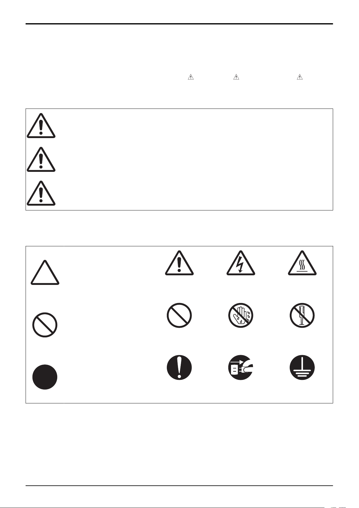
bizhub 235/215/195
A SAFETY AND IMPORTANT WARNING ITEMS > 2. DESCRIPTION
ITEMS FOR DANGE...
2. DESCRIPTION ITEMS FOR DANGER, WARNING
AND CAUTION
2.1 Description items in this Service Manual
In this Service Manual, each of three expressions “ DANGER”, “ WARNING”, and “
CAUTION” are defined as follows.
When servicing the product, the relevant works (disassembling, reassembling, adjustment,
repair, maintenance, etc.) need to be conducted with utmost care.
: Action having a high possibility of suffering
DANGER
WARNING
CAUTION
death or serious injury
: Action having a possibility of suffering death
or serious injury
: Action having a possibility of suffering a slight
wound and property damage
2.2 Description items for safety and important warning items
Symbols used for safety and important warning items are defined as follows:
: Precaution when
servicing the product.
General
precaution
: Prohibition when
servicing the product.
General
prohibition
: Direction when
servicing the product.
General
instruction
Electric hazard High temperature
Do not touch with
wet hand
Unplug Ground/Earth
Do not
disassemble
Illustrations representing the power plug and wall outlet used in the following descriptions are
only typical. Their shapes differ depending on the country or region.
A-3
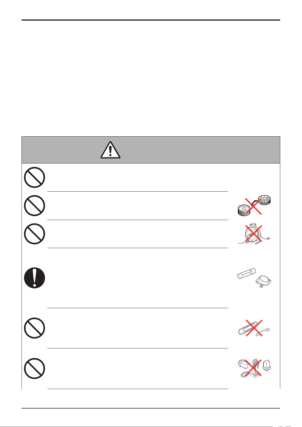
bizhub 235/215/195
A SAFETY AND IMPORTANT WARNING ITEMS > 3. SAFETY
WARNINGS
3. SAFETY WARNINGS
3.1 MODIFICATIONS NOT AUTHORIZED BY KONICA MINOLTA
BUSINESS TECHNOLOGIES, INC.
KONICA MINOLTA brand products are renowned for their high reliability. This reliability is
achieved through high-quality design and a solid service network.
Product design is a highly complicated and delicate process where numerous mechanical,
physical, and electrical aspects have to be taken into consideration, with the aim of arriving at
proper tolerances and safety factors. For this reason, unauthorized modifications involve a high
risk of degradation in performance and safety. Such modifications are therefore strictly
prohibited. the points listed below are not exhaustive, but they illustrate the reasoning behind
this policy.
3.1.1 Actions requiring special attention
WARNING
• Do not make any modifications to the product
unless otherwise instructed by KMBT.
• Do not use any part not specified by KMBT.
• Do not use any power cord or power plug not
specified by KMBT.
• Use only the protective fuses specified by
KMBT.
Use of any type of fuse or related part not
specified by KMBT makes safety devices
inoperative which may result in a fire from
high heat.
• Do not disable fuse functions or use a wire,
metal clip, solder, or other conductor in place
of the fuse.
Fire may result from high heat.
• Do not disable relay functions (for example,
inserting a piece of paper between relay
contacts to hamper circuit action.)
Fire may result from high heat.
A-4
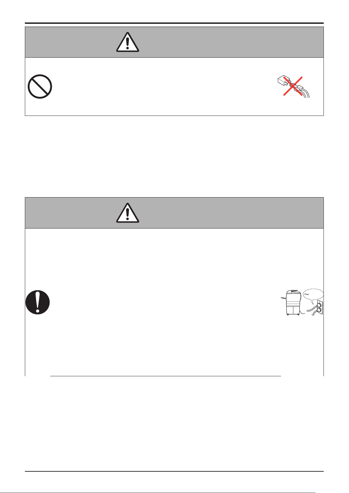
kw
bizhub 235/215/195
A SAFETY AND IMPORTANT WARNING ITEMS > 3. SAFETY
WARNINGS
WARNING
• Do not disable safety functions (for example,
interlocks and safety circuits).
Safety devices become inoperative, resulting
in fire from high heat, electric shock, or
injury.
3.2 POWER PLUG SELECTION
In some countries or areas, the power plug provided with the product may not fit the wall outlet
used in the area. In that case, it is the obligation of the customer engineer (hereafter called the
CE) to attach the appropriate power plug or power cord set in order to connect the product to
the supply.
3.2.1 Power Cord Set or Power Plug
WARNING
• Use a power supply cord set which meets the
following criteria:
- provided with a plug having configuration
intended for the connection to wall outlet
appropriate for the product's rated voltage and
current, and
- the plug has pin/terminal(s) for grounding, and
- provided with three-conductor cable having
enough current capacity, and
- the cord set meets regulatory requirements for
the area.
Use of inadequate cord set leads to fire or electric
shock.
A-5
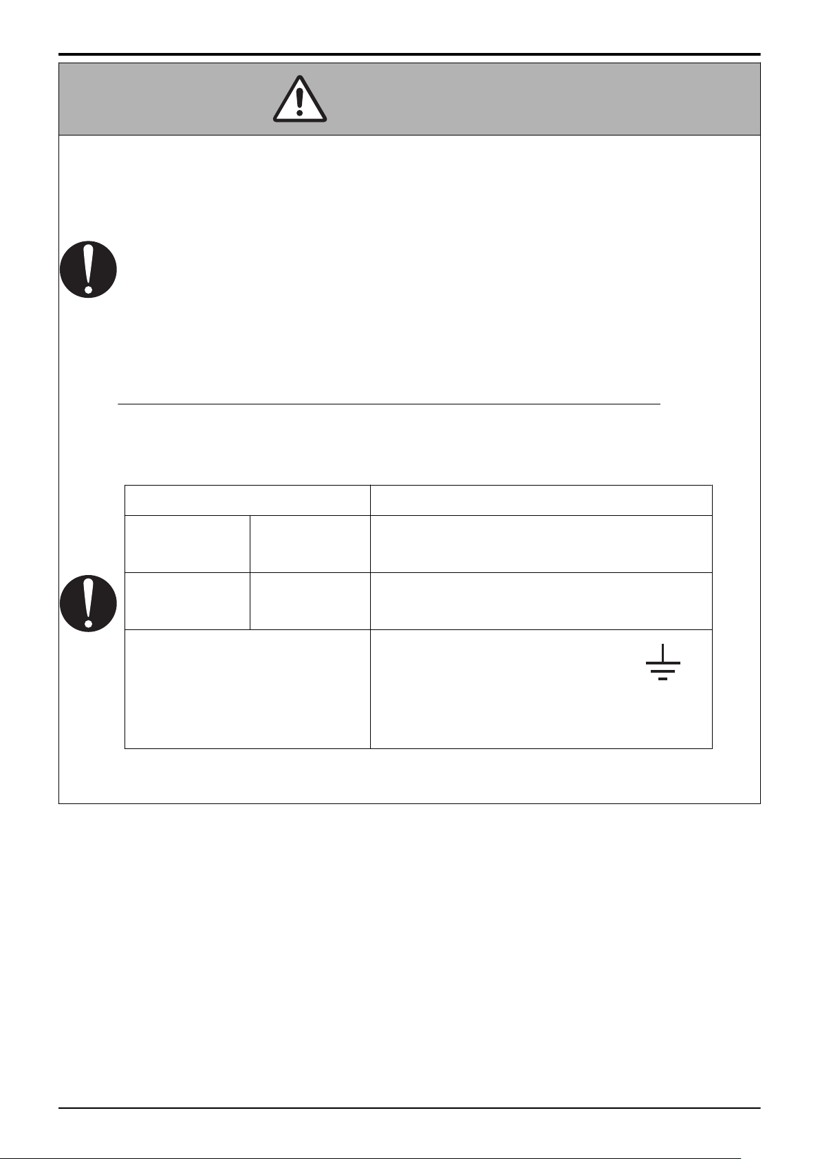
bizhub 235/215/195
• Attach power plug which meets the following criteria:
• The wires in the power supply cord shall be
A SAFETY AND IMPORTANT WARNING ITEMS > 3. SAFETY
WARNINGS
WARNING
- having configuration intended for the connection
to wall outlet appropriate for the product’s rated
voltage and current, and
- the plug has pin/terminal(s) for grounding, and
- meets regulatory requirements for the area.
Use of inadequate cord set leads to the product
connecting to inadequate power supply (voltage,
current capacity, grounding), and may result in fire
or electric shock.
connected to the terminals of the plug in accordance
with the following:
Color of the wire
Terminal of the plug
Marked with "L", "A" or "W"
Brown Black
or colored RED
Marked with "N"
Light Blue White
or colored BLACK
Marked with "E", "PE" or " "
Green-and-Yellow
or colored GREEN
or GREEN-AND-YELLOW
• Wrong connection may cancel safeguards within the
product, and results in fire or electric shock.
3.3 CHECKPOINTS WHEN PERFORMING ON-SITE SERVICE
KONICA MINOLTA brand products are extensively tested before shipping, to ensure that all
applicable safety standards are met, in order to protect the customer and customer engineer
(hereafter called the CE) from the risk of injury. However, in daily use, any electrical
equipment may be subject to parts wear and eventual failure. In order to maintain safety and
reliability, the CE must perform regular safety checks.
A-6
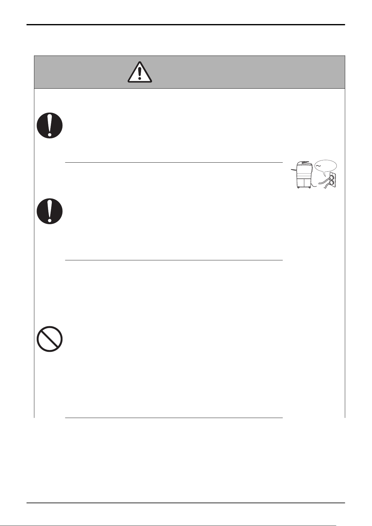
kw
bizhub 235/215/195
3.3.1 Power Supply
(1) Connection to Power Supply
• The power outlet should have a capacity of at
least the maximum power consumption and
be dedicated only to the product.
The current that can be passed through the
outlet is limited and any current exceeding
the limit could result in fire.
• If the wall outlet has two or more receptacles
and the product and another electrical
appliance are plugged into this wall outlet,
A SAFETY AND IMPORTANT WARNING ITEMS > 3. SAFETY
WARNINGS
WARNING
make sure that the total load does not exceed
the rating of the wall outlet. The current that
can be passed through the outlet is limited
and any current exceeding the limit could
result in a fire.
• Do not use any conversion plug adapter even
if the power plug shape does not match your
wall outlet.
The shapes of the power plug and the wall
outlet are set according to the voltage and
allowable current. Use of a conversion plug
adapter could result in an abnormal voltage
or insufficient current capacity, leading to a
fire. It may also result in an electric shock
due to a grounding failure.
If the plug shape does not match the wall
outlet, request the user to perform power
source installation work.
A-7
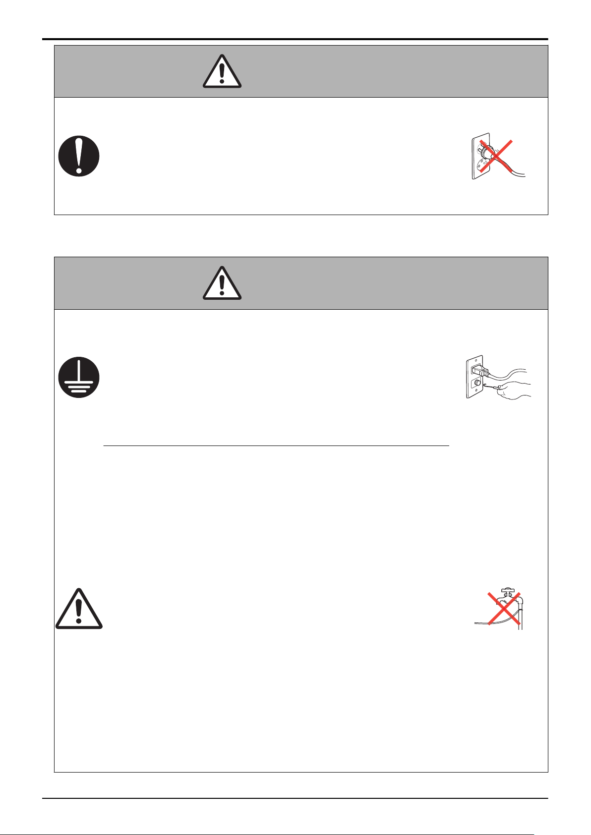
bizhub 235/215/195
• Make sure the power cord is plugged into the
wall outlet securely.
If the power plug is left loose in the wall
outlet, contact failure may occur, leading to
abnormal heating of the power plug and a
risk of fire.
(2) Ground Connection
A SAFETY AND IMPORTANT WARNING ITEMS > 3. SAFETY
WARNINGS
WARNING
WARNING
• Check whether the product is grounded
properly.
If current leakage occurs in an ungrounded
product, you may suffer electric shock while
operating the product.
Connect power plug to grounded wall
outlet.
• Make sure of correct ground connection.
If the grounding wire is connected to an
inappropriate part, there is a risk of
explosion or electric shock. Do not connect
the grounding wire to any of the following
parts:
a. Gas pipe: Gas explosion or fire may
result.
b. Lightning rod: Risk of electric shock or
fire during lightning.
c. Grounding wire for telephone line: Risk of
electric shock or fire during lightning.
d. Water pipe and faucet: These parts do
not serve as a ground connection
because of a plastic part that is very
often installed midway within the water
pipe.
A-8
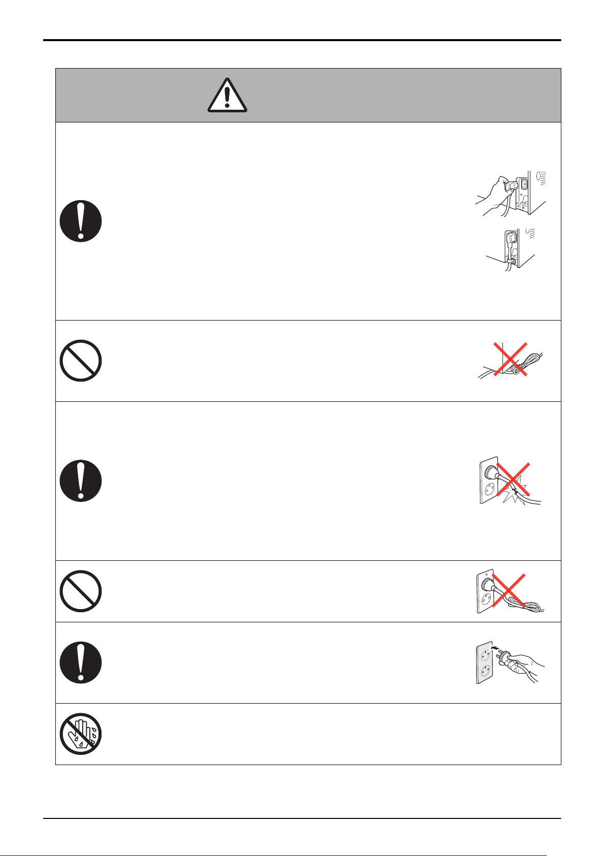
bizhub 235/215/195
(3) Power Plug and Cord
• When using the power cord set (inlet type)
that came with this product, make sure the
connector is securely inserted in the inlet of
the product.
When a securing measure is provided,
secure the cord with the fixture properly.
If the power cord (inlet type) is not
connected to the product securely, a
contact problem may lead to increased
resistance, overheating, and risk of fire.
A SAFETY AND IMPORTANT WARNING ITEMS > 3. SAFETY
WARNINGS
WARNING
• Do not allow the power cord to be stepped on
or pinched.
Overheating may occur there, leading to a
risk of fire.
• Check whether the power cord is damaged.
Check whether the sheath is damaged.
If the power plug, cord, or sheath is
damaged, replace with a new power cord
(with plug and connector on each end)
specified by KMBT. Using the damaged
power cord may result in fire or electric
shock.
• Do not bundle or tie the power cord.
Overheating may occur there, leading to a
risk of fire.
• Check whether dust is collected around the
power plug and wall outlet.
Using the power plug and wall outlet
without removing dust may result in fire.
• Do not insert the power plug into the wall
outlet with a wet hand.
The risk of electric shock exists.
A-9
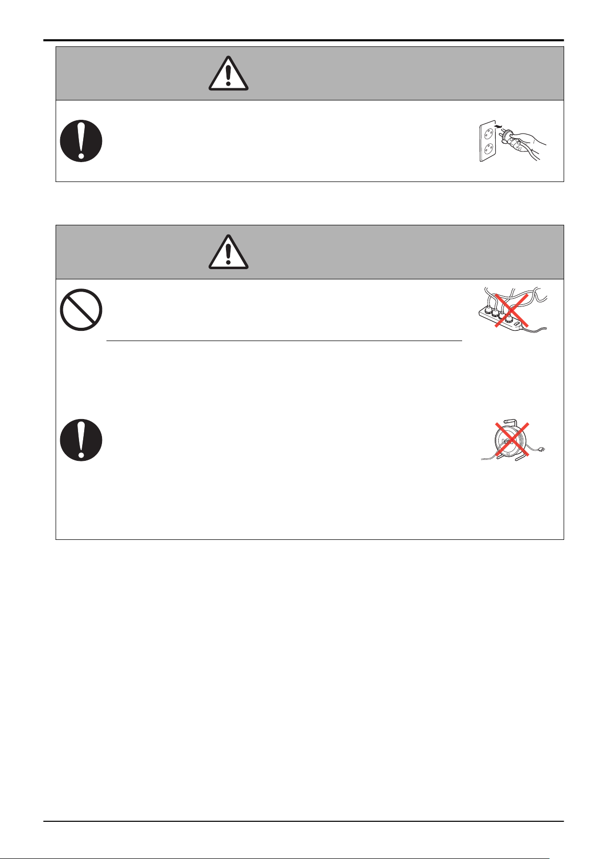
bizhub 235/215/195
(4) Wiring
A SAFETY AND IMPORTANT WARNING ITEMS > 3. SAFETY
WARNINGS
WARNING
• When unplugging the power cord, grasp the
plug, not the cable.
The cable may be broken, leading to a risk
of fire and electric shock.
WARNING
• Never use multi-plug adapters to plug multiple
power cords in the same outlet.
If used, the risk of fire exists.
• When an extension cord is required, use one
that meets the rated current, rated voltage,
and the relevant safety standards of the
country.
Current that can be passed through the
extension cable is limited and fire may
result from the use of an inappropriate type
of an extension cable.
Do not use an extension cable reel with the
cable taken up. Fire may result.
A-10
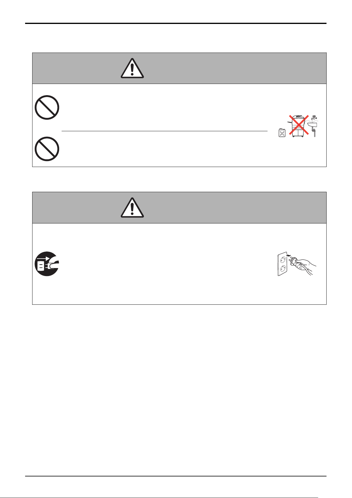
bizhub 235/215/195
3.3.2 Installation Requirements
(1) Prohibited Installation Places
A SAFETY AND IMPORTANT WARNING ITEMS > 3. SAFETY
WARNING
• Do not place the product near flammable
materials or volatile materials that may catch
fire.
A risk of fire exists.
• Do not place the product in a place exposed
to water such as rain.
A risk of fire and electric shock exists.
(2) When not Using the Product for a long time
WARNINGS
WARNING
• When the product is not to be used for an
extended period of time (for holidays, for
example), instruct the user to turn OFF the
power switch and unplug the power cord from
the power outlet.
Dust collected around the power plug and
outlet may cause fire.
A-11
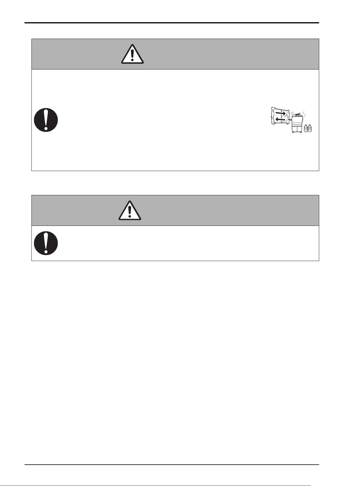
bizhub 235/215/195
(3) Ventilation
• The product generates ozone gas during
A SAFETY AND IMPORTANT WARNING ITEMS > 3. SAFETY
WARNINGS
CAUTION
operation.
If the smell of ozone is present in the
following cases, ventilate the room.
a. When the product is used in a poorly
ventilated room
b. When making a lot of copies
c. When using multiple products at the
same time
(4) Stability
CAUTION
• Be sure to lock the caster stoppers.
In the case of an earthquake, the product
may slide, leading to an injury.
A-12
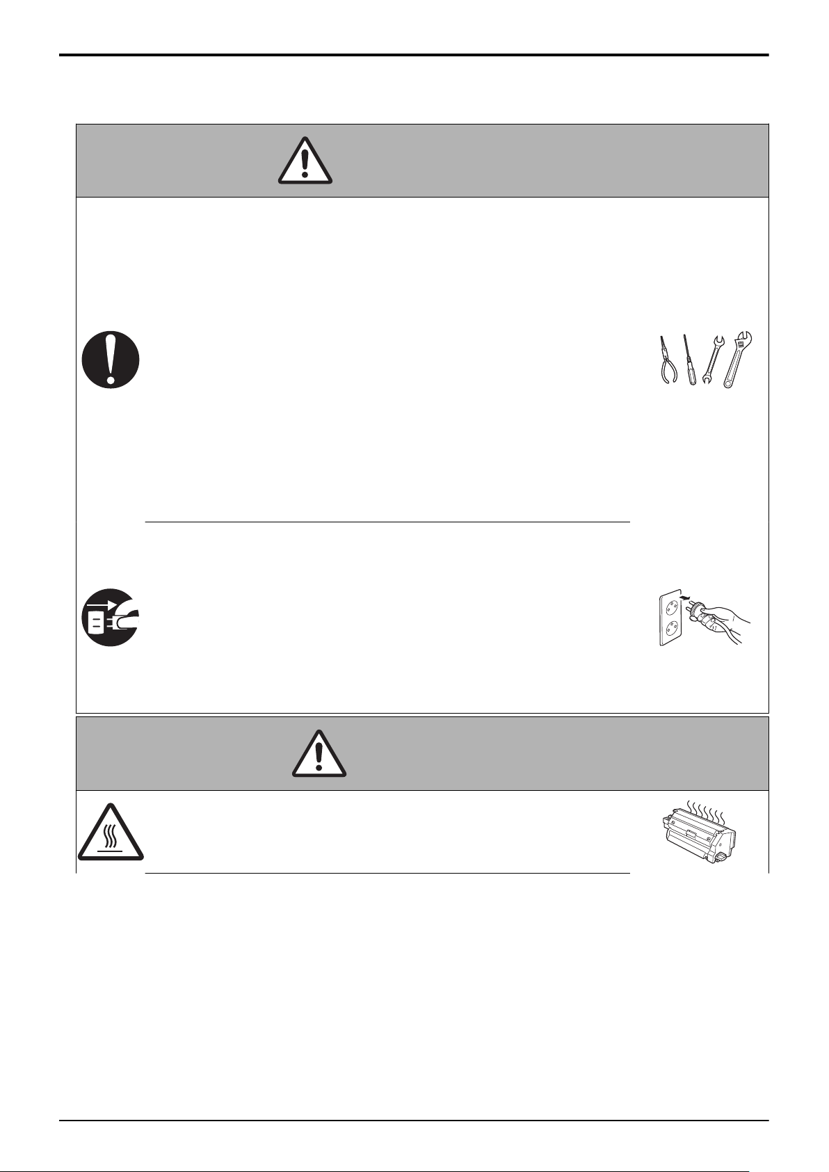
bizhub 235/215/195
3.3.3 After Service
(1) Inspection before Servicing
• Before conducting an inspection, read all
relevant documentation (service manual,
technical notices, etc.) and proceed with the
inspection following the prescribed procedure
using the recommended personal safety
equipment and using only the prescribed
tools.
Do not make any adjustment not described
in the documentation.
A SAFETY AND IMPORTANT WARNING ITEMS > 3. SAFETY
WARNINGS
WARNING
If the prescribed procedure or tool is not
used, the product may break and a risk of
injury or fire exists.
• Before conducting an inspection, be sure to
disconnect the power plugs from the Main
Body and Accessories (Options).
When the power plug is inserted into the
wall outlet, some units are still powered
even if the POWER switch is turned OFF.
A risk of electric shock exists.
CAUTION
• The area around the fixing unit is hot.
You may get burned.
A-13

bizhub 235/215/195
A SAFETY AND IMPORTANT WARNING ITEMS > 3. SAFETY
CAUTION
• Do not leave the machine unattended during
transportation, installation, and/or inspection.
If the machine is left unattended, face
protrusions toward the wall or take other
necessary precautions to prevent a user or
other person in the area from stumbling
over a protrusion of the machine or being
caught by a cable, possibly causing a fall to
the floor or other personal injury.
(2) Work Performed with the Product Powered On
WARNINGS
WARNING
• Take every care when making adjustments or
performing an operation check with the
product powered.
If you make adjustments or perform an
operation check with the external cover
detached, you may touch live or highvoltage parts or you may be caught in
moving gears or the timing belt, leading to a
risk of injury.
• Take every care when servicing with the
external cover detached.
High-voltage exists around the drum unit. A
risk of electric shock exists.
• If it is absolutely necessary to service the
machine with the door open or external
covers removed, always be attentive to the
motion of the internal parts.
A normally protected part may cause
unexpected hazards.
A-14

bizhub 235/215/195
• Do not keep gazing at a lamp light during the
service procedure with the product powered
ON.
Eyestrain may result.
(3) Safety Checkpoints
• When a product fault is reported from a user,
check parts and repair the fault appropriately
A SAFETY AND IMPORTANT WARNING ITEMS > 3. SAFETY
WARNINGS
CAUTION
WARNING
with safety in mind.
A damaged product, personal injury, or fire
may result.
• Whenever mounting an option on the
machine, be attentive to the motion of the
other workers performing the task.
Another worker may be injured by a pinch
point between the machine and the option.
• When mounting an option on the machine, be
careful about the clearance between the
machine and the option.
You may be injured with your finger or hand
pinched between the machine and the
option.
• When removing a part that secures a motor,
gear, or other moving part, disassembling a
unit, or reinstalling any of such parts and
units, be careful about moving parts and use
care not to drop any part or unit. During the
service procedure, give sufficient support for
any heavy unit.
You may be injured by a falling part or unit.
A-15

bizhub 235/215/195
A SAFETY AND IMPORTANT WARNING ITEMS > 3. SAFETY
WARNINGS
WARNING
• Check the external covers and frame for
possible sharp edges, burrs, and damage.
They can be a cause of injury during use or
servicing.
• When accessing a hard-to-view or narrow
spot, be careful about sharp edges and burrs
on the frame and parts.
They may injure your hands or fingers.
• Do not allow any metal parts such as clips,
staples, and screws to fall into the product.
They can short internal circuits and cause
electric shock or spark bursting into flame.
• Check wiring for pinched and any other
damage.
Current can leak, leading to a risk of
electric shock or fire.
• Check high-voltage cables and sheaths for
any damage.
Damage may lead to product failure and/or
the risk of fire.
• Do not disassemble or adjust the write unit
(PH unit) incorporating a laser.
The laser light can enter your eye, leading
to a risk of loss of eyesight.
• Do not supply power with the write unit (PH
unit) shifted from the specified mounting
position.
The laser light can enter your eye, leading
to a risk of loss of eyesight.
• After replacing a part to which AC voltage is
applied (e.g., optical lamp and fixing lamp), be
sure to check the installation state.
A risk of fire exists.
A-16

bizhub 235/215/195
A SAFETY AND IMPORTANT WARNING ITEMS > 3. SAFETY
WARNINGS
WARNING
• Check the interlock switch and actuator for
loosening and check whether the interlock
functions properly.
If the interlock does not function, you may
receive an electric shock or be injured
when you insert your hand in the product
(e.g., for clearing paper jam).
• Make sure the wiring cannot come into
contact with sharp edges, burrs, or other
pointed parts.
Damage may lead to the risk of electric
shock or fire.
• Make sure that all screws, components,
wiring, connectors, etc. that were removed for
safety check and maintenance have been
reinstalled in the original location. (Pay
special attention to forgotten connectors,
pinched cables, forgotten screws, etc.)
A risk of product trouble, personal injury,
electric shock, and fire exists.
• Never use any flammable or combustible
spray, fluid, gas, or similar substance in and
around the product.
Do not use any flammable or combustible
dust spray, in particular, to clean the interior
of the product.
Fire or explosion may result.
CAUTION
• Carefully remove all toner remnants and dust
from electrical parts and electrode units such
as a charging corona unit.
Toner remnants and dust may lead to
product failure and/or the risk of fire.
A-17

bizhub 235/215/195
A SAFETY AND IMPORTANT WARNING ITEMS > 3. SAFETY
WARNINGS
CAUTION
• Check electrode units such as a charging
corona unit for deterioration and signs of
leakage.
Damage may lead to product failure and/or
the risk of fire.
• When replacing a battery, replace it with a
new one as specified.
Dispose of the used battery as instructed
on its packaging or by local ordinance.
There is a risk of explosion if the battery is
replaced with an incorrect type.
(4) Handling of Consumables
WARNING
• For handling of consumables (toner,
developer, photoconductor, etc.) and their
storage precautions, see MSDS.
(5) Handling of Service Materials
CAUTION
• Handle with care according to MSDS.
Use of solvent may involve explosion, fire,
or personal injury.
3.4 FUSE
CAUTION
Double pole / neutral fusing
ATTENTION
Double pôle / fusible sur le neutre.
A-18

bizhub 235/215/195
A SAFETY AND IMPORTANT WARNING ITEMS > 3. SAFETY
3.5 Used Batteries Precautions
3.5.1 ALL Areas
CAUTION
Danger of explosion if battery is incorrectly replaced.
Replace only with the same or equivalent type recommended by the manufacturer.
Dispose of used batteries according to the manufacturer's instructions.
3.5.2 Germany
VORSICHT!
Explosionsgefahr bei unsachgemäßem Austausch der Batterie.
Ersatz nur durch denselben oder einen vom Hersteller empfohlenen gleichwertigen Typ.
Entsorgung gebrauchter Batterien nach Angaben des Herstellers.
3.5.3 France
ATTENTION
WARNINGS
Il y a danger d’explosion s’il y a remplacement incorrect de la batterie.
Remplacer uniquement avec une batterie du même type ou d’un type équivalent recommandé
par le constructeur.
Mettre au rebut les batteries usagées conformément aux instructions du fabricant.
3.5.4 Denmark
ADVARSEL!
Lithiumbatteri - Eksplosionsfare ved fejlagtig håndtering.
Udskiftning må kun ske med batteri af samme fabrikat og type.
Levér det brugte batteri tilbage til leverandøren.
3.5.5 Finland, Sweden
VAROlTUS
Paristo voi räjähtää, jos se on virheellisesti asennettu.
Vaihda paristo ainoastaan laitevalmistajan suosittelemaan tyyppiin.
Hävitä käytetty paristo valmistajan ohjeiden mukaisesti.
VARNING
Explosionsfara vid felaktigt batteribyte.
Använd samma batterityp eller en ekvivalent typ som rekommenderas av apparattillverkaren.
Kassera använt batteri enligt fabrikantens instruktion.
3.5.6 Norway
ADVARSEL
Eksplosjonsfare ved feilaktig skifte av batteri.
Benytt samme batteritype eller en tilsvarende type anbefalt av apparatfabrikanten.
Brukte batterier kasseres i henhold til fabrikantens instruksjoner.
A-19

[1]
[2]
bizhub 235/215/195
A SAFETY AND IMPORTANT WARNING ITEMS > 3. SAFETY
WARNINGS
3.6 Laser Safety
3.6.1 Laser Safety
This is a digital machine certified as a Class 1 laser product. There is no possibility of danger
from a laser, provided the machine is serviced according to the instruction in this manual.
3.6.2 Internal Laser Radiation
• This product employs a Class 3B laser diode that emits an invisible laser beam. The laser
diode and the scanning polygon mirror are incorporated in the print head unit.
• The print head unit is NOT A FIELD SERVICEABLE ITEM. Therefore, the print head unit
should not be opened under any circumstances.
semiconductor laser
Maximum power of the laser diode 7 mW
Maximum average radiation power (*)
bizhub
235/215/195
6.9 μW
Wavelength 770 to 800 nm
*at laser aperture of the Print Head Unit
[1]
Laser Aperture of the Print Head Unit [2] Print Head Unit
(1) U.S.A., Canada (CDRH Regulation)
• This machine is certified as a Class 1 Laser product under Radiation Performance
Standard according to the Food, Drug and Cosmetic Act of 1990. Compliance is
mandatory for Laser products marketed in the United States and is reported to the Center
for Devices and Radiological Health (CDRH) of the U.S. Food and Drug Administration of
the U.S. Department of Health and Human Services (DHHS). This means that the device
does not produce hazardous laser radiation.
• The label shown on “A.3.6.3 Laser Safety Label” indicates compliance with the CDRH
regulations and must be attached to laser products marketed in the United States.
A-20

bizhub 235/215/195
A SAFETY AND IMPORTANT WARNING ITEMS > 3. SAFETY
CAUTION
Use of controls, adjustments or performance of procedures other
than those specified in this manual may result in hazardous radiation
exposure.
semiconductor laser
Maximum power of the laser diode 7 mW
Wavelength 770 to 800 nm
(2) All Areas
CAUTION
WARNINGS
Use of controls, adjustments or performance of procedures other
than those specified in this manual may result in hazardous radiation
exposure.
semiconductor laser
Maximum power of the laser diode 7 mW
Wavelength 770 to 800 nm
(3) Denmark
ADVARSEL
Usynlig laserstråling ved åbning, når sikkerhedsafbrydere er ude af
funktion. Undgå udsættelse for stråling. Klasse 1 laser produkt der
opfylder IEC60825-1 sikkerheds kravene.
halvlederlaser
Laserdiodens højeste styrke 7 mW
bølgelængden 770 to 800 nm
(4) Finland, Sweden
LUOKAN 1 LASERLAITE
KLASS 1 LASER APPARAT
A-21

bizhub 235/215/195
A SAFETY AND IMPORTANT WARNING ITEMS > 3. SAFETY
VAROITUS!
Laitteen käyttäminen muulla kuin tässä käyttöohjeessa mainitulla
tavalla saattaa altistaa käyttäjän turvallisuusluokan 1 ylittävälle
näkymättömälle lasersäteilylle.
puolijohdelaser
Laserdiodin suurin teho 7 mW
aallonpituus 770 to 800 nm
VARNING!
Om apparaten används på annat sätt än i denna bruksanvisning
specificerats, kan användaren utsättas för osynlig laserstrålning, som
WARNINGS
överskrider gränsen för laserklass 1.
halvledarlaser
Den maximala effekten för laserdioden 7 mW
våglängden 770 to 800 nm
VARO!
Avattaessa ja suojalukitus ohitettaessa olet alttiina näkymättomälle
lasersäteilylle. Älä katso säteeseen.
VARNING!
Osynlig laserstråining när denna del är öppnad och spärren är
urkopplad. Betrakta ej stråien.
(5) Norway
ADVERSEL
Dersom apparatet brukes på annen måte enn spesifisert i denne
bruksanvisning, kan brukeren utsettes for unsynlig laserstrålning,
som overskrider grensen for laser klass 1.
halvleder laser
Maksimal effekt till laserdiode 7 mW
A-22

bizhub 235/215/195
A SAFETY AND IMPORTANT WARNING ITEMS > 3. SAFETY
halvleder laser
bølgelengde 770 to 800 nm
WARNINGS
A-23

bizhub 235/215/195
A SAFETY AND IMPORTANT WARNING ITEMS > 3. SAFETY
3.6.3 Laser Safety Label
A laser safety label is attached to the outside of the machine as shown below.
WARNINGS
3.6.4 Laser Caution Label
A laser caution label is attached to the inside of the machine as shown below.
3.6.5 PRECAUTIONS FOR HANDLING THE LASER EQUIPMENT
• Be sure to unplug the power cord whenever performing a service job in the laser beam path
(around the PH unit).
• If it is absolutely unavoidable to perform a service job with the power cord plugged in, strictly
observe the following precautions:
1. Before starting the service job, take off your watch, ring, and other reflective articles and
be sure to wear laser protective goggles.
2. Keep other personnel away from the work site.
A-24

bizhub 235/215/195
A SAFETY AND IMPORTANT WARNING ITEMS > 3. SAFETY
3. Do not bring any highly reflective tool into the laser beam path during the service
procedure.
WARNINGS
A-25

bizhub 235/215/195
A SAFETY AND IMPORTANT WARNING ITEMS > 4. WARNING
INDICATIONS ON THE ...
4. WARNING INDICATIONS ON THE MACHINE
Caution labels shown below are attached in some areas on/in the machine.
When accessing these areas for maintenance, repair, or adjustment, special care should be
taken to avoid burns and electric shock.
4.1 Warning indications inside the machine
CAUTION
You may be burned or injured if you touch any area that you are
advised not to touch by any caution label. Do not remove caution
labels. If any caution label has come off or soiled and therefore the
caution cannot be read, contact our service office.
A-26

• This area generates high voltage.
Be careful not to touch here when
the power is turned ON to avoid
getting an electric shock.
CAUTION
To avoid electric shock, after turning
OFF the power switch,do not touch the
DC power supply unit for 10 minutes.
If the DC power supply unit is faulty,
it may take time
before its voltage drops sufficiently.
WARNING
WARNING
Do not touch power supply unit for
10 min. after shutting off the machine.
Electric Shock from Stored Charge
on Capacitors!
bizhub 235/215/195
4.2 Warning indications on the boards
WARNING
• To avoid electric shock, after turning OFF the power
switch, do not touch the DC power supply unit for 10
minutes.
If the DC power supply unit is faulty, it may take time
before its voltage drops sufficiently.
A SAFETY AND IMPORTANT WARNING ITEMS > 4. WARNING
INDICATIONS ON THE ...
A-27

bizhub 235/215/195
A SAFETY AND IMPORTANT WARNING ITEMS > 5. MEASURES
TO TAKE IN CASE OF...
5. MEASURES TO TAKE IN CASE OF AN ACCIDENT
1. If an accident has occurred, the distributor who has been notified first must immediately take
emergency measures to provide relief to affected persons and to prevent further damage.
2. If a report of a serious accident has been received from a customer, an on-site evaluation
must be carried out quickly and KMBT must be notified.
3. To determine the cause of the accident, conditions and materials must be recorded through
direct on-site checks, in accordance with instructions issued by KMBT.
4. For reports and measures concerning serious accidents, follow the regulations specified by
every distributor.
A-28

bizhub 235/215/195
B NOTATION OF THE CONTENTS > 1. NOTATION OF THE
CONTENTS
B NOTATION OF THE CONTENTS
1. NOTATION OF THE CONTENTS
1.1 Product name
In this manual, each of the products is described as follows:
(1) bizhub 235/215/195 Main body
(2) Microsoft Windows XP: Windows XP
Microsoft Windows Vista: Windows Vista
Microsoft Windows 7: Windows 7
Microsoft Windows Server 2003 Windows Server 2003
Microsoft Windows Server 2008 Windows Server 2008
When the description is made in combination of the OS's mentioned above:
Windows XP/Vista/7
Windows Server 2008/Server 2003
1.2 Brand name
The company names and product names mentioned in this manual are the brand name or the registered trademark of each company.
1.3 Paper feed direction
• When the long side of the paper is parallel with the feeding direction, it is called short edge feeding. The feeding direction which is
perpendicular to the short edge feeding is called the long edge feeding.
• Short edge feeding will be identified with [S (abbreviation for Short edge feeding)] on the paper size. No specific notation is added for the
long edge feeding.
When the size has only the short edge feeding with no long edge feeding, [S] will not be added to the paper size.
<Example>
Paper size
A4 Transverse feed A4
A3 Longitudinal feed A3
Feed direction Notation
Longitudinal feed A4S
B-1

bizhub 235/215/195 C PRODUCT SPECIFICATIONS > 1. bizhub 235/215/195
C PRODUCT SPECIFICATIONS
1. bizhub 235/215/195
1.1 Type
Type Scanner/printer integrated desktop type
Scanning resolution 600 x 600 dpi
Platen Stationary
Original scanning CIS module optical scanning system
Scanning light source LED
Printing process Laser electrostatic printing system
PC drum type OPC drum: 9ST
Paper feeding system Tray 1: Separator pad system
Exposure system LD exposing system/polygon mirror scan system
Exposure resolution 600 x 600 dpi
Developing system Dry 2 components developing method, HMT developing system
Charging system DC comb electrode scorotron system
Neutralizing system Non-erase
Image transfer system Roller image transfer system
Paper separating system Neutralization needle bias superimposed voltage, separating claws and combination of curvature
Fusing system Roller fusing system
Heating system Halogen lamp
1.2 Functions
Types of original
Max. original size A3 or 11 x 17
Max. original weight 2 kg
Multiple copies 1 to 999
Warm-up time 15 sec. or less (110 V/120 - 127 V/220 - 240 V)
Image loss Leading edge: 4 mm (3/16 inch), trailing edge: 4 mm (3/16 inch),
First copy time
(A4, 8 1/2 x 11)
Processing speed 100 mm/s
Copying/printing speed for multi-copy
cycle
(A4, 8 1/2 x 11)
Fixed zoom ratios Europe, China Full size: x 1.00
Variable zoom ratios x 0.25 to x 4.00 (in 0.01 increments)
Paper size used Tray 1 Metric: A3, B4, A4S, B5S, A4, A5S, B5, B6S, A5, A6S, 16K, 16KS, 8K
Copy exit tray capacity 250 sheets
Multi bypass tray: Small roller separation system with torque limiter
system
Sheets, books, and three-dimensional objects
(when the power switch is turned ON from a stabilized state at ambient temperature of 23°C /
73.4°F and rated source voltage)
Rear edge: 4 mm (3/16 inch), front edge: 4 mm (3/16 inch)
6.5 sec. or less
(Values in conditions of paper fed from tray 1 at a room temperature of 23°C and with a rated
power source)
bizhub 235 23 sheets/min. (Plain paper)
bizhub 215 21 sheets/min. (Plain paper)
bizhub 195 19 sheets/min. (Plain paper)
Latin America areas for inch Full size: x 1.00
Latin America area for metric Full size: x 1.00
Taiwan Full size: x 1.00
Multi bypass tray
Inch: 11 x 17, 8 1/2 x 14, 8 1/2 x 11S, 7 1/4 x 10 1/2S, 8 1/2 x 11, 5 1/2 x 8
1/2S, 7 1/4 x 10 1/2, 5 1/2 x 8 1/2
Foolscap: 8 1/2 x 13 1/2, 8 1/2 x 13, 8 1/4 x 13, 8 1/8 x 13 1/4, 8 x 13, 8 13/20
x 13
7 sheets/min. (Card1/2)
7 sheets/min. (Card1/2)
7 sheets/min. (Card1/2)
Reduction: x 0.25, x 0.50, x 0.70, x 0.81
Enlargement: x 1.15, x 1.41, x 2.00, x 4.00
Reduction: x 0.25, x 0.50, x 0.64, x 0.78
Enlargement: x 1.21, x 1.29, x 2.00, x 4.00
Reduction: x 0.25, x 0.50, x 0.70, x 0.78
Enlargement: x 1.15, x 1.41, x 2.00, x 4.00
Reduction: x0.25, x 0.50, x 0.70, x 0.78
Enlargement: x 1.15, x 1.41, x 2.00, x 4.00
C-1

bizhub 235/215/195 C PRODUCT SPECIFICATIONS > 1. bizhub 235/215/195
1.3 Paper
Tray 1 Multi bypass tray
Type
Size Width Metric: 90 to 297 mm
Plain paper (64 to 90 g/m2 / 17 to 24
lb)
Card 1 (91 to 120 g/m2 / 24.25 to
31.75 lb)
Card 2 (121 to 157 g/m2 / 32.25 to
41.75 lb)
OHP film 10 sheets 10 sheets Envelopes 10 sheets 10 sheets
Postcards - - Labels - - -
Length Metric: 139.7 to 431.8 mm
250 sheets 100 sheets 250 sheets
20 sheets 20 sheets -
20 sheets 20 sheets -
Inch: 3 9/16 to 11 11/16 inch
Inch: 5 1/2 to 17 inch
(MB-505)
Tray 2 to 5 (PF-507)
Metric: 182 to 297 mm
Inch: 7 1/6 to 11 11/16 inch
Metric: 182 to 431.8 mm
Inch: 7 1/6 to 17 inch
1.4 Materials
Parts name Number of prints Type name
Toner bottle 5,400 prints *1 TN119
12,000 prints *1 TN118/TN119H *2
Developer 55,000 prints *1 DV116
Drum 55,000 prints *1 DR114
*1: Specification value
*2: TN119H is only for China.
1.5 Print volume
1.5.1 bizhub 215
Area
China 3,500 sheets/month 15,000 sheets/month
Europe 3,000 sheets/month 15,000 sheets/month
Asia/Pacific 2,500 sheets/month 15,000 sheets/month
Mexico 3,000 sheets/month 15,000 sheets/month
Average Maximum
1.5.2 bizhub 195
Area
China 2,500 sheets/month 12,000 sheets/month
Asia/Pacific 1,500 sheets/month 12,000 sheets/month
Mexico 2,000 sheets/month 12,000 sheets/month
Average Maximum
1.6 Machine specifications
Power requirements
Max power consumption 110V: 1,300W
Dimensions Main body only 570 mm (W) x 570 mm (D) x 458mm (H) *1
Voltage AC110 V, AC120-127V, AC220-240V
Current 110 V 12.0A
120 V 11.0A
127 V 11.0A
230 V 6.0A
Frequency 50/60 Hz
120V: 1,300W
127V: 1,300W
230V: 1,300W
22.4 inch (W) x 22.4 inch (D) x 18 inch (H) *1
Main body + PF-507 570 mm (W) x 570 mm (D) x 542mm (H) *1
22.4 inch (W) x 22.4 inch (D) x 20.6 inch (H) *1
Main body + MB-505 607 mm (W) x 570 mm (D) x 458mm (H) *1
23.9 inch (W) x 22.4 inch (D) x 18 inch (H) *1
C-2

bizhub 235/215/195 C PRODUCT SPECIFICATIONS > 1. bizhub 235/215/195
Main body + MB-505+DF-625 607 mm (W) x 579 mm (D) x 538mm (H) *2
Space requirements 1,109 mm (W) x 1,038 mm (D) x 1323 mm (H) or 43.7 inch (W) x 40.9 inch (D) x 52.1 inch (H) *3
Weight Approx. 26.5 kg /58.4 lb (Main body only: without toner bottle, developer, Original cover and Multi bypass
unit)
*1: Height up to the original glass.
*2: When the multi bypass tray MB-505 is mounted.
*3: Space requirements is the necessary area when DF-625, PF-507, MB-505 and AD-509 are mounted and bypass tray is fully opened.
23.9 inch (W) x 22.8 inch (D) x 21.2inch (H) *2
1.7 Operating environment
Temperature 10 to 30° C / 50 to 86° F (with a fluctuation of 10° C / 18° F or less per hour)
Humidity 15 to 85% (Relative humidity with a fluctuation of 10%/h)
1.8 Print function
Type Built-in printer controller
RAM 128 MB (shared with the copier)
Interface USB2.0, Ethernet 10Base-T/100Base-TX (option)
Printer language GDI, PCL(Option)
Print resolution GDI: 600 x 600 dpi, PCL: 600 dpi x 600 dpi (1200dpi x 600dpi)
Windows XP Home Edition (SP1 or later)
Windows XP Professional (SP1 or later)
Windows XP Professional x64 Edition
Windows Vista Business *
Windows Vista Enterprise *
Windows Vista Home Basic *
Windows Vista Home Premium *
Windows Vista Ultimate *
Windows 7 Home Premium/Professional/Ultimate *
Supported OS for printer driver
Windows Server 2003, Standard Edition (SP1 or later)
Windows Server 2003, Enterprise Edition (SP1 or later)
Windows Server 2003 R2, Standard Edition
Windows Server 2003 R2, Enterprise Edition
Windows Server 2003, Standard x64 Edition
Windows Server 2003, Enterprise x64 Edition
Windows Server 2003 R2, Standard x64 Edition
Windows Server 2003 R2, Enterprise x64 Edition
Windows Server 2008 Standard *
Windows Server 2008 Enterprise *
* 32 bits (x86)/64 bits (x64) environment are supported
1.9 Scan function
Scannable range 297 mm x 431.8 mm
Scanner
TWAIN/WIA
Scanning mode Binary/Grayscale/Color
Scanning resolution 150/300/600 dpi
Driver TWAIN/WIA Driver
Windows XP Home Edition (SP1 or later)
Windows XP Professional (SP1 or later)
Windows XP Professional x64 Edition
Windows Vista Business *
Windows Vista Enterprise *
Windows Vista Home Basic *
Windows Vista Home Premium *
Windows Vista Ultimate *
Windows 7 Home Premium/Professional/Ultimate *
Supported OS
Windows Server 2003, Standard Edition (SP1 or later)
Windows Server 2003, Enterprise Edition (SP1 or later)
Windows Server 2003 R2, Standard Edition
Windows Server 2003 R2, Enterprise Edition
Windows Server 2003, Standard x64 Edition
Windows Server 2003, Enterprise x64 Edition
Windows Server 2003 R2, Standard x64 Edition
Windows Server 2003 R2, Enterprise x64 Edition
Windows Server 2008 Standard *
Windows Server 2008 Enterprise *
* 32 bits (x86)/64 bits (x64) environment are supported
C-3

bizhub 235/215/195 C PRODUCT SPECIFICATIONS > 2. AD-509
2. AD-509
2.1 Type
Name Automatic Duplex Unit (AD-509)
Type Switchback and Circulating Duplex Unit
Installation Mounted on the right side door of main unit
Document Alignment Center
2.2 Paper type
Paper Type
Paper Size Width Metric: 139.7 to 297 mm
2.3 Machine specifications
Power Requirements
Dimensions *1
Weight *1
• *1: Values given only for reference when the Duplex Unit is demounted from the machine, since it is standard on the machine.
2.4 Operating environment
• Conforms to the operating environment of the main body.
NOTE
• These specifications are subject to change without notice.
Plain paper (64 to 90 g/m2 / 17 to 24 lb)
Inch: 5 1/2 to 11 11/16 inch
Length Metric: 139.7 to 431.8 mm
Inch: 5 1/2 to 17 inch
DC 24 V (supplied from the main body)
DC 3.3 V (supplied from the main body)
Metric: 386 mm (W) x 107 mm (D) x 225 mm (H)
Inch: 15 3/16 inch (W) x 4 3/16 inch (D) x 8 7/8 inch (H)
1.5 kg (3 5/16 lb)
C-4

bizhub 235/215/195 C PRODUCT SPECIFICATIONS > 3. DF-625
3. DF-625
3.1 Type
Name Reverse Automatic Document Feeder
Type Feeding order Forward
Feed section Paper feed from top of stack
Turnover Switch back system
Paper Exit Straight exit system
Installation Screw cramp to the main unit
Document Alignment Center
Document Loading Left image side up
3.2 Functions
Original feed mode 1-sided original, 2-sided original, mixed original, FAX mode
Scanning speed (A4 or Letter)
3.3 Paper type
Original type
Original Size
Original loading capacity
3.4 Paper feed prohibited originals
• If fed, trouble occurrence will be highly possible.
Type of Original
Original that is stapled or clipped. Feed failure, damage to the original, or drive failure due to clip
Book original Feed failure, damage to the original, or drive failure
Original weighing less than 35 g/m2 or 129 g/m2 or more Feed failure
Torn original Feed failure, damaged sheet
Highly curled original (15 mm or more) Original misfeed due to dog-ear or skew
OHP transparencies Feed failure
Label Sheet Feed failure
Offset master Feed failure
Photographic paper or Glossy original such as gloss-coated paper Feed failure
Sheets clipped or notched Damaged sheet
Sheets patched Patched part folded or torn sheet, Sheets misfed
3.5 Paper feed not guaranteed originals
• If fed, paper feed will be possible to some extent but trouble occurrence will be possible.
Type of Original
Sheets lightly curled (Curled amount: 10 - 15 mm) Dog-eared, exit failure
Heat Sensitive Paper Edge folded, exit failure, transport failure
Coated Paper (Ink Jet Paper) Take-up failure, transport failure
Translucent paper Take-up failure, transport failure
Paper immediately after paper exit from the main unit Take-up failure, transport failure
Binary: 46 pages/min. (150 x 150 dpi, 300 x300 dpi), 23 pages/min. (600 x 600 dpi)
Grayscale: 38 pages/min. (150 x 150 dpi), 16 pages (600 x 600 dpi)
Color: 20 pages/min. (150 x 150 dpi), 8 pages/min. (600 x 600 dpi)
Standard Mode (Plain Paper) 1-Sided Mode: 35 to 128 g/m2 (9.25 to 34 lb)
2-Sided Mode: 50 to 128 g/m2 (13.25 to 34 lb)
Mixed Original Detection Mode (Plain
Paper)
FAX Mode (Plain Paper) 1-Sided Mode: 35 to 128 g/m2 (9.25 to 34 lb)
Standard Mode (Plain Paper) • Metric: A5 to A3
Mixed Original Detection Mode (Plain
Paper)
FAX Mode (Plain Paper) • Metric: A5 to A3
Max. 70 sheets (80 g/m2 / 21 1/4 lb)
clogging
1-Sided Mode: 50 to 128 g/m2 (13.25 to 34 lb)
2-Sided Mode: 50 to 128 g/m2 (13.25 to 34 lb)
•
Inch: 5 1/2 × 8 1/2S to 11 × 17
Refer to the C.3.6 Mixed original feed chart.
•
Inch: 5 1/2 × 8 1/2S to 11 × 17
• Width: 139.7 mm to 297 mm
• Length (1-Sided Mode): 139.7 mm to 1,000 mm
• Length (2-Sided Mode): 139.7 mm to 431.8 mm
Possible Trouble
Possible Trouble
C-5

bizhub 235/215/195 C PRODUCT SPECIFICATIONS > 3. DF-625
Type of Original Possible Trouble
Paper with many punched holes (e.g., loose leaf) limited to vertical
feeding
Sheets with 2 to 4 holes Transport failure
Sheets two-folded or Z-folded Transport failure, image deformation
Sheets with rough surface (e.g., letterhead) Take-up failure
Sheets folded Image deformation, multi-page feed, take-up failure
• *: Before using loose leaf or folded original, straighten the perforations or fold first. The permissible lift amount is 15 mm or less.
Multi-page feed due to flashes from holes
3.6 Mixed original feed chart
For Metric
Max. Original Size
297 mm 257 mm 210 mm 182 mm 148 mm
Mixed Original Size A3 A4 B4 B5 A4S A5 B5S A5S
297 mm
257 mm
210 mm
182 mm B5S NG NG NG NG NG NG OK 148 mm A5S NG NG NG NG NG NG NG OK
For Inch
Mixed Original Size 11 x 17
11
8 1/
2
5 1/
2
A3 OK OK - - - - - A4 OK OK - - - - - B4 NG NG OK OK - - - B5 NG NG OK OK - - - -
A4S NG NG NG NG OK OK - -
A5 NG NG NG NG OK OK - -
Max. Original Size
11
8 1/2 x 11 8 1/2 x 14 8 1/2 x 11S 5 1/2 x 8 1/28 1/2 x 5 1/2S
11 x 17 OK OK - - - -
8 1/2 x 11
8 1/2 x 14
8 1/2 x 11S
8 1/2 x 5 1/
8 1/2 x 5 1/2S
OK Mixed Original Feed available (Tilted with in 1.5 % or less)
NG NO. Mixed Original Feed
- Can not Set Original
2
OK OK - - - -
NG NG OK OK OK -
NG NG OK OK OK -
NG NG OK OK OK -
NG NG NG NG NG OK
8 1/
2
5 1/
2
3.7 Machine specifications
Power Requirements
Max. power consumption 14.4 W or less
Size
Weight
DC 24 V (supplied from the main unit)
DC 3.3 V (supplied from the main unit)
546 mm (W) x 486 mm (D) x 80 mm (H)
21.5 inch (W) x 19.1 inch (D) x 3.1 inch (H)
5.3 kg (11 11/16 lb)
3.8 Operating
• Conforms to the operating environment of the main unit.
NOTE
• These specifications are subject to change without notice.
C-6

bizhub 235/215/195 C PRODUCT SPECIFICATIONS > 4. MB-505
4. MB-505
4.1 Paper
Paper Type
Paper Size
Number of loadable sheets
4.2 Machine specifications
Power requirements
Max. power consumption 8W or less
Dimensions*1 446 mm (W) x 469 mm (D) x 82 mm (H)
Weight*1 1.7kg
• *1: Values given only for reference when the Duplex Unit is demounted from the machine, since it is standard on the machine.
4.3 Operating environment
• Conforms to the operating environment of the main body.
NOTE
• These specifications are subject to change without notice.
Plain paper, Recycled paper (64 g/m2 to 90 g/m2)
Special paper : CARD1 (91 g/m2 to 120 g/m2), CARD2 (121 g/m2 to 157 g/m2), OHP film, Envelopes
Metric: A3, B4, A4S, B5S, A4, A5S, B5, B6S, A5, A6S, 16K, 16KS, 8K
Inch: 11 x 17, 8 1/2 x 14, 8 1/2 x 11S, 7 1/4 x 10 1/2S, 8 1/2 x 11, 5 1/2 x 8 1/2S, 7 1/4 x 10 1/2, 5 1/2 x 8
1/2
Foolscap : 8 1/2 x 13 1/2, 8 1/2 x 13, 8 1/4 x 13, 8 1/8 x 13 1/4, 8 x 13, 8 13/20 x 13
Width: 90 mm to 297 mm, Length:139.7 mm to 431.8 mm
Plain paper, Recycled paper: 100 sheets
Special paper: CARD1 and 2(10 sheets), OHP film(10 sheets), Envelopes(10 sheets),
DC 24 V (supplied from the main body)
DC 3.3 V (supplied from the main body)
C-7

bizhub 235/215/195 C PRODUCT SPECIFICATIONS > 5. PF-507
5. PF-507
5.1 Type
Name 1 way Paper Take-Up Cabinet
Type Front loading type 1 way paper take-up device
Installation Desk type
Document Alignment Center
5.2 Paper type
Paper type Plain paper, Recycled paper (15-15/16 lb to 23-15/16 lb (64 g/m2 to 90 g/m2))
Paper size
Number of loadable sheets 250 sheets
5.3 Machine specifications
Power Requirements
Max. Power Consumption 9W or less
Dimensions
Weight 5.4kg or 11-7/8 lb
5.4 Operating environment
• Conforms to the operating environment of the main body.
NOTE
• These specifications are subject to change without notice.
Metric: A3 to B5S (Refer to the PB.2.3 Paper size detecting mechanism for details.)
Inch: 11 x 17, 8 1/2 x 14, 8 1/2 x 11, 8 1/2 x 11S
DC 24 V (supplied from the main body)
DC 3.3 V (supplied from the main body)
570 mm (W) × 530 mm (D) × 108 mm (H)
22-7/16 inches (W) x 20-7/8 inches (D) x 4-1/4 inches (H)
C-8

bizhub 235/215/195 C PRODUCT SPECIFICATIONS > 6. FK-510
6. FK-510
Applicable lines PSTN (Public Switched Telephone Network), PBX (Private Branch Exchange)
Standard 203 dpi x 98 dpi (8 dot/mm x 3.85 line/mm)
Fine 203 dpi x 196 dpi (8 dot/mm x 7.7 line/mm)
Resolution
Compatibility ECM/Super G3
Modem speed 2.4 to 33.6 kbps
Transmit speed 3 second/page (A4, V.34, 33.6 kbps, JBIG)
Coding method MH, MR, MMR, JBIG
Memory for receiving 16 MB (1024 pages can be stored)
Recording paper size
Original sizes
Functions
Super fine 203 dpi x 392 dpi (8 dot/mm x 15.4 line/mm)
Super fine (Only for the
ADF transmission)
Maximum size: A3
Maximum length: 1000 mm (When receiving the data of an original that is longer than the paper sizes set in the
trays, the data is printed according to the setting of [REDUCTION RX].)
Flatbed Maximum: A3
ADF Maximum: 297 mm (Width) x 1000 mm (Length)
ADF (Super fine only) Maximum: 297 mm (Width) x 900 mm (Length)
One-touch dial 32 key
Speed dial 250 stations can be registered
Group dial 32 groups (50 stations can be registered as one group.)
Program dial 4 key (No.29 to 32)
Other supported functions On hook dial, Automatic redial, Manual redial, Chain dial
406 dpi x 392 dpi (16 dot/mm x 15.4 line/mm)
C-9

[2]
[3]
[1]
[4]
[6]
[7]
[8]
[9]
[12]
[5]
[11]
[10]
bizhub 235/215/195 D OVERALL COMPOSITION > 1. SYSTEM CONFIGURATION
D OVERALL COMPOSITION
1. SYSTEM CONFIGURATION
[1] bizhub 235/215/195 [2] Original Cover (OC-512)*1
[3] Reverse Automatic Document Feeder (DF-625) [4] Automatic Duplex Unit (AD-509)
[5] Multi bypass tray (MB-505) *2 [6] Paper Feeder Unit (PF-507)*3
[7] Desk (DK-708) [8] Desk (DK-707)
[9] Desk (DK-706) [10] Mechanical Counter (MC-504)*4
[11] Image Controller (IC-209) or Network Card (NC-504) [12] FAX kit (FK-510)
*1: Standard on the bizhub 195/235. Standard on the product shipped to China of the bizhub 215.
*2: Standard on the bizhub 195/235. Standard on the product shipped to except North America and Europe of the bizhub 215.
*3: Standard on the bizhub 235. (1 unit)
*4: Standard on the product shipped to North America of the bizhub 215
D-1

[1]
[2]
[4]
[5]
[3]
[6]
[7]
[11]
[10]
[8]
[9]
bizhub 235/215/195 D OVERALL COMPOSITION > 2. CROSS SECTIONAL VIEW
2. CROSS SECTIONAL VIEW
[1] Reverse Automatic Document Feeder (DF-625) [2] Scanner
[3] Exit section [4] Fusing unit
[5] Automatic Duplex Unit (AD-509) [6] Imaging unit
[7] Transfer section [8] Multiple bypass tray
[9] Tray1 [10] Write section
[11] Toner supply section - -
D-2

bizhub 235/215/195 D OVERALL COMPOSITION > 3. PAPER PATH
3. PAPER PATH
D-3

IR
CIS
MFP board (MFPB)
BB Module
DF-625
FAXB
Power Supply
Unit
Process (Motor, Sensor, Clutch, DC Power)
MB-505
High voltage unit
AD-509
Control System Line
Image Bus Line
PH
Panel
Operation
Panel
FAX Operation
PF-507
NC-504 or
IC-209
[1]
[2]
[3]
[6]
[7]
[8]
[9]
[12]
[13]
[11]
[5]
[10]
[4]
bizhub 235/215/195 D OVERALL COMPOSITION > 4. OVERALL CONFIGRATION
4. OVERALL CONFIGRATION
4.1 Control Block Diagram
4.2 Image creation process
[10] Paper separation
[11] Cleaning • Residual toner on the surface of the drum is scraped off.
Photoelectric
[1]
conversion
IR Image
[2]
processing
PH Image
[3]
processing
[4] Drum
[5] Drum charging • A uniform negative DC charge is deposited across the entire surface of the drum.
[6] Laser exposure • The laser beam strikes the surface of the drum, forming an electrostatic latent image.
[7] Developing
[8] Paper feed • Paper is supplied from the paper feed tray.
[9] Image transfer
• A CIS sensor is used to convert the image data represented by light reflected off the original to a corresponding
electric signal which, in turn, is output to the IR image processing section.
• The analog electric signal is converted to an 8-bit digital image signal (A/D conversion) which, in turn, goes
through appropriate corrections before being output to the PH image processing section.
• After going through corrections, the digital image signal is converted to a corresponding electric signal (D/A
conversion), with which the laser is turned ON or OFF as necessary.
• Made up of an aluminum pipe coated with a photoconductive layer, on which an electrostatic latent image is
formed.
• Toner negatively charged in the developer mixing chamber is attracted onto the electrostatic latent image
changing it to a visible, developed image.
• A developing bias (Vb) is applied to the developing roller to prevent toner from being attracted onto those areas
of the drum which correspond to the background areas of the original.
• A DC positive charge is applied to the image transfer roller to transfer the visible image on the surface of the
drum onto the paper.
• The drum paper separator fingers remove paper from the surface of the drum.
• The charge neutralizing plate neutralizes any charge left on the paper.
D-4

bizhub 235/215/195 D OVERALL COMPOSITION > 4. OVERALL CONFIGRATION
• The toner is then recycled back to the developing unit.
[12] Fusing
[13] Paper exit • The paper is fed out onto the exit tray.
• The developed image is permanently fused to the paper by the combination of heat and pressure applied by
the fusing roller.
D-5

bizhub 235/215/195 E SERVICE TOOL > 1. Service material list
E SERVICE TOOL
1. Service material list
Name Shape Material No. Remarks
Cleaning pad 000V-18-1 10pcs/1pack
Isopropyl alcohol
E-1

bizhub 235/215/195 E SERVICE TOOL > 2. CE tool list
2. CE tool list
Tool name Shape Quantity Parts No. Remarks
PC positioning jig 1 4021 4362 ##
E-2

bizhub 235/215/195 F MAINTENANCE > 1. Concept of periodical maintenance
F MAINTENANCE
1. Concept of periodical maintenance
1.1 Concept of periodical maintenance
• The cleaning or replacement cycle of the parts of the machine and options that need periodical maintenance depends on the total counter
value or each counter value provided by [SERVICE MODE] -> [COUNTER] -> [PM COUNTER].
1.2 bizhub 235/215/195
1.2.1 Periodical maintenance 1 (Total counter; every 55,000 counts)
Section Description/part name Qt. Clean Check Lubrication Replace Descriptions
Overall Paper feed and image
Conveyance section Registration roller — ●
Processing section Ds collars — ●
conditions
Appearance — ● ●
Pre-image transfer guide plate — ●
Developer scattering prevention
plate
Drum separator fingers — ●
Developer 1 ●
Drum 1 ●
Cleaning blade 1 ●
Drum charge corona assy 1 ●
1.2.2 Periodical maintenance 2 (PM counter; every 165,000 counts)
Section
Fusing section Fusing unit 1 ●
Paper feed section Feed roller 1 ●
Conveyance section Transfer roller unit 1 ●
Description/part name Qt. Clean Check Lubrication Replace Descriptions
Separation pad 1 ●
1.2.3 Periodical maintenance 3 (SUPPLIES counter; every 165,000 counts)
Section
Processing section Imaging unit 1 ●
Description/part name Qt. Clean Check Lubrication Replace Descriptions
1.3 Option
1.3.1 Reverse automatic document feeder (DF-625)
(1) Periodical maintenance 1 (PM counter; every 55,000 counts)
Section
Overall Paper feed and image
Paper feed section Pick-up roller — ●
Conveyance section Roller and rolls — ●
Scanning section Scanning guide — ●
(2) Periodical maintenance 2 (PM counter; every 110,000 counts)
Section
Paper feed section Separation roller 1 ●
1.3.2 Paper feeder unit (PF-507)
(1) Periodical maintenance 1 (PM counter; every 165,000 counts)
Section
Paper feed section Feed roller 1 ●
Description/part name Qt. Clean Check Lubrication Replace Descriptions
conditions
Appearance — ● ●
Feed roller — ●
Separation roller — ●
Document transport sensor — ●
Description/part name Qt. Clean Check Lubrication Replace Descriptions
Description/part name Qt. Clean Check Lubrication Replace Descriptions
— ●
— ●
— ●
F-1

bizhub 235/215/195 F MAINTENANCE > 1. Concept of periodical maintenance
1.3.3 Multi bypass tray (MB-505)
(1) Periodical maintenance 1 (PM counter; every 165,000 counts)
Section Description/part name Qt. Clean Check Lubrication Replace Descriptions
Paper feed section Feed roller 1 ●
Separation roller 1 ●
F-2

bizhub 235/215/195 F MAINTENANCE > 2. PERIODICAL MAINTENANCE ITEMS
2. PERIODICAL MAINTENANCE ITEMS
2.1 Periodical replacement parts list
2.1.1 Periodical replacement parts list
• To ensure that the machine produces good copies and to extend its service life, it is recommended that the maintenance jobs described in
this schedule be carried out as instructed.
• Replace with reference to the numeric values displayed on the total counter, the each PM counter or the messages displayed on the control
panel.
•
Maintenance conditions are based on the case of A4 or 8 1/2 x 11, standard mode* and low power mode OFF.
B/W
* Standard mode bizhub 235 2 pages per job
bizhub 215 2 pages per job
bizhub 195 2 pages per job
2.1.2 bizhub 235/215/195
Classification Parts name Parts No. Qt.
Processing
section
Fusing section Fusing
Paper feed
section
Conveyance
section
*1: Only for China
*2: Actual durable cycle (PM counter value)
*3: Replace those parts at the same time.
Developer — 1 55,000 F.3.1.1 Replacing the developer
Drum — 1 55,000 F.3.1.2 Replacing the drum
Cleaning blade A0XX 3618 ## 1 55,000 F.3.1.4 Replacing the cleaning blade
Drum charge corona
assy
Toner bottle (TN119) *1 — 1 5,400 F.3.1.6 Replacing the toner bottle
Toner bottle (TN118) — 1 12,000
Toner bottle (TN119H)
*1
Imaging unit — 1 165,000 F.3.1.10 Replacing the imaging unit
unit
Feed roller A0XX 5602 ## 1 165,000 *3 F.3.4.1 Replacing the tray 1 feed roller
Separation pad
Transfer roller unit
220V 240V
110V A3PE PP3X ## 1
120V -
127V
A1XU R701 ## 1
— 1
A3PE PP3V ## 1
A3PE PP3W
##
A0XX PP6E ## 1
A0XX PP6H ## 1
2.1.3 Option
Classification Parts name Parts No. Qt.
DF-625 Separation roller
PF-507 Feed roller
MB-505 Feed roller
Separation roller
• *1: Replace those parts at the same time.
A3JH PP3B ## 1
A3PF PP1H ## 1
A0XX 5947 ## 1
4034 0151 ## 1
2.2 Periodical cleaning parts list
2.2.1 bizhub 235/215/195
• Clean with reference to the numeric values displayed on the total counter.
Classification
Processing
section
Ds collars 55,000 F.3.1.7 Cleaning of the Ds collars
Developer scattering prevention plate 55,000
Drum separator fingers 55,000
Parts name Cleaning cycle Descriptions Ref.Page
Replacing
cycle
55,000 F.3.1.3 Replacing the drum charge
165,000 *2 F.3.3.1 Replacing the fusing unit
1
165,000 F.3.4.2 Replacing the tray 1 separation
165,000 F.3.5.1 Replacing the transfer roller unit
Replacing
cycle
110,000 F.4.1.1 Replacing the separation roller
165,000 F.5.1.1 Replacing the feed roller
165,000 *1 F.6.1.1 Replacing the feed roller
165,000 F.6.1.2 Replacing the separation roller
Descriptions Ref. page
corona assy
pad
Descriptions Ref. page
(DF-625)
(PF-507)
(MB-505)
assy (MB-505)
F.3.1.9 Cleaning of the developer
scattering prevention plate
F.3.1.8 Cleaning of the drum separator
fingers
F-3

bizhub 235/215/195 F MAINTENANCE > 2. PERIODICAL MAINTENANCE ITEMS
Classification Parts name Cleaning cycle Descriptions Ref.Page
Conveyance
section
Registration roller 55,000 F.3.2.1 Cleaning of the registration roller
Pre-image transfer guide plate 55,000
F.3.2.2 Cleaning of the pre-image
transfer guide plate
2.2.2 Option
• Clean with reference to the numeric values displayed on the PM counter.
Classification Parts name Cleaning cycle Descriptions Ref.Page
DF-625
Feed roller 55,000
Pick-up roller 55,000
Separation roller 55,000
Roller and rolls 55,000
Scanning guide 55,000
Document transport sensor 55,000
F.4.1.2 Cleaning of the pick-up roller/feed
roller/separation roller (DF-625)
F.4.1.2 Cleaning of the pick-up roller/feed
roller/separation roller (DF-625)
F.4.1.2 Cleaning of the pick-up roller/feed
roller/separation roller (DF-625)
F.4.2.1 Cleaning of the roller and rolls
(DF-625)
F.4.3.1 Cleaning of the scanning guide
(DF-625)
F.4.1.3 Cleaning of the document
transport sensor (DF-625)
2.3 Concept of parts life
2.3.1 Life value of consumables and parts
Life specification value means an actual life terminated when prints are made under the conditions as defined in the next section, "F.2.3.2
Conditions for life specifications values"
Description
Developer
Drum
Cleaning blade
PC drum charge corona
Fusing unit
*1: To check the life count, select [Service Mode] -> [COUNTER] -> [SUPPLIES COUNTER] -> [I/U Life].
*2: To check the life count, select [Service Mode] -> [COUNTER] -> [PM COUNTER] -> [FUSING].
*3: When the count reaches the maximum life value, printing is not allowed.
The distance travelled by the drum is converted to a corresponding
number of printed pages of A4 paper at 2P/J.
The number of sheets of paper fed out of the copier is counted. 165,000 counts
2.3.2 Conditions for life specifications values
Item
Copying type 2P/J
Paper size
PV/M
Original density B/W 6%
bizhub 235
bizhub 215
bizhub 195
Average 3,500 (China) / 3,000 (US, EU) / 2,500 (other marketing areas)
Maximum 15,000
Average 3,500 (China) / 3,000 (US, EU) / 2,500 (other marketing areas)
Maximum 15,000
Average 2,500 (China) / 1,500 (Others except for China)
Maximum 12,000
A4 or 8 1/2 x 11
Life value Max. life value
55,000
*1
*2
Description
69,000
*1, *3
—
F-4

[1]
[2]
[2]
[1]
[3]
[4]
[1]
[2]
[3]
bizhub 235/215/195
F MAINTENANCE > 3. PERIODICAL MAINTENANCE PROCEDURE
3. PERIODICAL MAINTENANCE PROCEDURE bizhub 235/215/195
NOTE
• The alcohol described in the cleaning procedure of maintenance represents the isopropyl alcohol.
3.1 Processing section
3.1.1 Replacing the developer
(1) Periodically replacing parts/cycle
Developer: Every 55,000 counts
(2) Procedure
1. Remove the toner bottle.
F.3.1.6 Replacing the toner bottle
2. Remove the imaging unit.
F.3.1.10 Replacing the imaging unit
3. Release the tabs [1] and disconnect the connector [2] from the
imaging unit.
bizhub 235/215/195
4. Remove two screws [1] in the rear of the imaging unit.
5. Remove three screws [2] at the front of the imaging unit.
6. While slightly pulling the area below the drum (diagonally shaded
area) in the direction of arrow, separate the drum unit [3] from the
developing unit [4].
7. Remove two screws [1], release four tabs [2], and remove the
plate [3].
F-5

[1]
[2]
[3]
[1]
[1]
[2]
[3]
[1]
[2]
(a)
(b)
(c)
[2]
[1]
[3]
bizhub 235/215/195
F MAINTENANCE > 3. PERIODICAL MAINTENANCE PROCEDURE
bizhub 235/215/195
8. Place the drum unit [1] as shown on the illustration.
9. Attach the PC positioning jig [2].
NOTE
• Be sure to place the drum unit on a sheet of paper or
similar item.
• To avoid the developer from leaking at the point [3] on the
illustration, place the drum unit on a sheet of paper or
similar item so that the working place will not have
developer.
10. While turning the gear [1] in the direction of the arrow, dump the
remaining toner from the drum unit.
NOTE
• Lightly shake the drum unit before dumping the toner so
that caked part will also be removed.
• Turn the drum about three complete turns.
11. Place the drum unit [1] as shown on the illustration.
12. While turning the gear [2] in the direction of the arrow, dump the
remaining developer from the screw.
NOTE
• Turn the drum about three complete turns.
13. Remove three screws [1] of the developing unit, and remove the
developer scattering prevention plate [2].
NOTE
• When securing the developer scattering prevention plate,
tighten screws in the order of one on one edge (a), one at
the center (b), and one on the other edge (c).
• When attaching the developer scattering prevention plate,
make sure that the tabs of the developer scattering
prevention plate are inserted into the slots [3].
14. Tilt the developing unit as shown in the illustration. While turning
the gear [1] in the direction of the arrow, dump the developer [2].
NOTE
• Make sure that the magnet roller [3] is placed on the upper
side of the developing unit when dumping the developer
[2]. Old developer adhering to the gears and rolls can
cause their breakage.
• Turning the gear backward at this time could damage the
sheet for cleaning the TCR sensor.
• Dump developer until almost no developer sticks to the
magnet roller.
F-6

[2]
[1]
[1]
[2]
bizhub 235/215/195
Remove the PC positioning jig.
16.
17. To reinstall, reverse the order of removal.
NOTE
• Do not install the toner bottle at this stage.
18. Turn ON the power switch.
19. Perform [SERVICE MODE] - [FUNCTION] - [TCR AUTO ADJUST].
NOTE
• To obtain the correct adjustment value, make this adjustment while the toner bottle is removed.
20. Install the toner bottle.
F MAINTENANCE > 3. PERIODICAL MAINTENANCE PROCEDURE
15. While turning the gear [1] in the direction of the arrow, pour a
packet of developer [2].
NOTE
• Shake the packet of developer well before pouring.
3.1.2 Replacing the drum
(1) Periodically replacing parts/cycle
Drum: Every 55,000 counts
(2) Procedure
1. Remove the toner bottle.
F.3.1.6 Replacing the toner bottle
2. Remove the imaging unit.
F.3.1.10 Replacing the imaging unit
3.
Release the tabs [1] and disconnect the connector [2] from the
imaging unit.
bizhub 235/215/195
F-7

[2]
[1]
[3]
[4]
[1]
[5]
[3]
[2]
[4]
[1]
bizhub 235/215/195
F MAINTENANCE > 3. PERIODICAL MAINTENANCE PROCEDURE
bizhub 235/215/195
4. Remove two screws [1] in the rear of the imaging unit.
5. Remove three screws [2] at the front of the imaging unit.
6. While slightly pulling the area below the drum (diagonally shaded
area) in the direction of arrow, separate the drum unit [3] from the
developing unit [4].
7. Place the drum unit [1] as shown in the illustration.
NOTE
• Developer can spill from the portion [2] shown in the
illustration. Place the drum unit on a sheet of paper to
prevent developer from making the site dirty.
8. Remove two screws [3] and remove the bracket [4] that holds the
drum in place.
9. Remove the drum [5].
NOTE
• Protect the drum that has been removed with a protective
cloth.
• If the drum has been replaced with a new one, apply a
coat of toner to the surface of the new drum.
F.3.1.5 Application of toner
10. To reinstall, reverse the order of removal.
11. Turn ON the power switch.
12. Select [SERVICE MODE] -> [CLEAR DATA] -> [SUPPLIES COUNTER] -> [I/U Life] and clear the counter value.
3.1.3 Replacing the drum charge corona assy
(1) Periodically replacing parts/cycle
Drum charge corona assy: Every 55,000 counts
(2) Procedure
1. Remove the toner bottle.
F.3.1.6 Replacing the toner bottle
2. Remove the imaging unit.
F.3.1.10 Replacing the imaging unit
3. Remove the drum.
F.3.1.2 Replacing the drum
4.
Remove the drum charge corona [1] as shown in the illustration.
5. To reinstall, reverse the order of removal.
F-8

[1]
[2]
(a)
(b)
(c)
[1]
[1]
20 to 25 mm
10 to 15 mm
20 to 30 mm
Drum
[1]
bizhub 235/215/195
3.1.4 Replacing the cleaning blade
(1) Periodically replacing parts/cycle
Cleaning blade: Every 55,000 counts
(2) Procedure
1. Remove the toner bottle.
F.3.1.6 Replacing the toner bottle
2. Remove the imaging unit.
F.3.1.10 Replacing the imaging unit
3. Remove the drum.
F.3.1.2 Replacing the drum
4. Remove the drum charge corona assy.
F.3.1.3 Replacing the drum charge corona assy
F MAINTENANCE > 3. PERIODICAL MAINTENANCE PROCEDURE
bizhub 235/215/195
5. Remove three screws [1], and remove the cleaning blade [2].
NOTE
• When securing the cleaning blade, tighten screws in the
order of one on one edge (a), one at the center (b), and
one on the other edge (c).
• When the cleaning blade has been replaced, apply a coat
of toner to the surface of the drum.
F.3.1.5 Application of toner
6. To reinstall, reverse the order of removal.
3.1.5 Application of toner
NOTE
• Perform these steps when the drum and/or cleaning blade have been replaced.
1.
With the imaging unit divided into the drum assy and developing
assy, install the PC positioning jig [1] in the rear of the drum assy.
2. Using a brush, apply a light coat of toner to the surface of the drum
[1].
<<Area to which toner is to be applied.>>
3. Hold both ends [1] of the drum with your both hands and turn the
drum a half turn in the direction of the arrow.
F-9

[1]
[1]
[1]
[2]
bizhub 235/215/195
F MAINTENANCE > 3. PERIODICAL MAINTENANCE PROCEDURE
4. Using a brush, apply a light coat of toner to the surface of the
cleaning blade [1].
3.1.6 Replacing the toner bottle
(1) Periodically replacing parts/cycle
• Toner bottle (TN119): Every 5,400 prints
• Toner bottle (TN118/TN119H): Every 12,000 prints
(2) Procedure
NOTE
• Do not install the toner bottle while the imaging unit is not installed. Doing so can cause a toner spill.
1. Open the front door.
2. Rotate the empty toner bottle [1] counterclockwise to unlock it.
3. Pull out the toner bottle [1].
bizhub 235/215/195
4. Remove the new toner bottle from its packaging, and shake it side
to side 5 to 10 times.
5. Insert the toner bottle [1] into the machine a little.
6. While holding the toner bottle, slowly peel off the seal [2].
F-10

[1]
[2]
[1]
[1]
[2]
bizhub 235/215/195
3.1.7 Cleaning of the Ds collars
(1) Periodically cleaning parts/cycle
Ds collars: Every 55,000 counts
(2) Procedure
1. Remove the toner bottle.
F.3.1.6 Replacing the toner bottle
2. Remove the imaging unit.
F.3.1.10 Replacing the imaging unit
F MAINTENANCE > 3. PERIODICAL MAINTENANCE PROCEDURE
7. Insert the toner bottle [1] into the machine.
NOTE
• Align the tip of the knob of the toner bottle with the mark
of ▼ [2] indicated on the machine as shown in the
illustration.
8. Rotate the toner bottle [1] clockwise to lock it.
9. Close the front cover.
3.
Release the tabs [1] and disconnect the connector [2] from the
imaging unit.
bizhub 235/215/195
F-11

[2]
[1]
[3]
[4]
[1]
[1]
[1]
bizhub 235/215/195
F MAINTENANCE > 3. PERIODICAL MAINTENANCE PROCEDURE
bizhub 235/215/195
4. Remove two screws [1] in the rear of the imaging unit.
5. Remove three screws [2] at the front of the imaging unit.
6. While slightly pulling the area below the drum (diagonally shaded
area) in the direction of arrow, separate the drum unit [3] from the
developing unit [4].
7. Using a cleaning pad with alcohol, wipe the two Ds collars [1]
clean of dirt.
8. To reinstall, reverse the order of removal.
3.1.8 Cleaning of the drum separator fingers
(1) Periodically cleaning parts/cycle
Drum paper separator fingers: Every 55,000 counts
(2) Procedure
1. Remove the toner bottle.
F.3.1.6 Replacing the toner bottle
2. Remove the imaging unit.
F.3.1.10 Replacing the imaging unit
3. Remove the drum.
F.3.1.2 Replacing the drum
3.1.9 Cleaning of the developer scattering prevention plate
(1) Periodically cleaning parts/cycle
Developer scattering prevention plate: Every 55,000 counts
(2) Procedure
1. Remove the toner bottle.
2. Remove the imaging unit.
F.3.1.6 Replacing the toner bottle
F.3.1.10 Replacing the imaging unit
4.
Using a cleaning pad with alcohol, wipe the five separator fingers
[1] clean of dirt.
F-12

[1]
[2]
[2]
[1]
[3]
[4]
[3]
[1]
[2]
(a)
(b)
(c)
[1]
bizhub 235/215/195
F MAINTENANCE > 3. PERIODICAL MAINTENANCE PROCEDURE
bizhub 235/215/195
3. Release the tabs [1] and disconnect the connector [2] from the
imaging unit.
4. Remove two screws [1] in the rear of the imaging unit.
5. Remove three screws [2] at the front of the imaging unit.
6. While slightly pulling the area below the drum (diagonally shaded
area) in the direction of arrow, separate the drum unit [3] from the
developing unit [4].
9. To reinstall, reverse the order of removal.
7. Remove three screws [1], and remove the developer scattering
prevention plate [2].
NOTE
• When securing the developer scattering prevention plate,
tighten screws in the order of one on one edge (a), one at
the center (b), and one on the other edge (c).
• When attaching the developer scattering prevention plate,
make sure that the tabs of the developer scattering
prevention plate are inserted into the slots [3].
8. Using a brush, whisk dust and dirt off the surface of the developer
scattering prevention plate [1].
F-13

[1] [2]
[4]
[3]
[1]
[2]
[1]
bizhub 235/215/195
F MAINTENANCE > 3. PERIODICAL MAINTENANCE PROCEDURE
3.1.10 Replacing the imaging unit
(1) Periodically replacing parts/cycle
Imaging unit: Every 165,000 prints
(2) Procedure
1. Open the right door.
2. Open the front door.
3. Remove the toner bottle.
F.3.1.6 Replacing the toner bottle
NOTE
• Do not install the toner bottle while the imaging unit is not installed. Doing so can cause a toner spill.
8. To reinstall, reverse the order of removal.
4. Remove the screw [1], and remove the cover [2].
5. Disconnect the connector [3].
6. Remove the harness from guide [4].
7. Remove two screws [1], and remove the imaging unit [2].
NOTE
• Do not install the toner bottle while the imaging unit is not
installed.
• When installing the imaging unit, use care not to damage
the drum.
• Before attempting to install the imaging unit, be sure to
fully open the right door. Take care that, if the imaging
unit is installed with the right door locked halfway, it may
interfere with the transfer roller.
• When inserting the imaging unit, do that slowly and, when
you are sure that the drum gear contacts the mating part,
push the imaging unit all the way into position. If this step
is done all at once, the drum gear could be damaged.
• If the right door is closed with the imaging unit removed,
pressing the unlock button does not open the right door
automatically. For opening the right door in this status,
move the door manually while pressing the unlock button.
3.2 Conveyance section
3.2.1 Cleaning of the registration roller
(1) Periodically cleaning parts/cycle
Registration roller: Every 55,000 counts
(2) Procedure
1. Open the right door.
2.
Using a cleaning pad dampened with alcohol, wipe the registration
roller [1] clean of dirt.
NOTE
• Do not touch or scratch the photo conductor.
bizhub 235/215/195
3.2.2 Cleaning of the pre-image transfer guide plate
(1) Periodically cleaning parts/cycle
Pre-image transfer guide plate: Every 55,000 counts
(2) Procedure
1. Remove the toner bottle.
F-14

[1]
[2]
[2]
[1]
[3]
[4]
[1]
[1]
bizhub 235/215/195
F.3.1.6 Replacing the toner bottle
2. Remove the imaging unit.
F.3.1.10 Replacing the imaging unit
F MAINTENANCE > 3. PERIODICAL MAINTENANCE PROCEDURE
bizhub 235/215/195
3. Release the tabs [1] and disconnect the connector [2] from the
imaging unit.
4. Remove two screws [1] in the rear of the imaging unit.
5. Remove three screws [2] at the front of the imaging unit.
6. While slightly pulling the area below the drum (diagonally shaded
area) in the direction of arrow, separate the drum unit [3] from the
developing unit [4].
7. Using a cleaning pad with alcohol, wipe the pre-image transfer
upper guide plate [1] clean of dirt.
8. Using a cotton bud dampened with alcohol, clean the groove [1]
inside the pre-image transfer upper guide plate.
F-15

[1]
[1]
[2]
[3]
bizhub 235/215/195
3.3 Fusing section
3.3.1 Replacing the fusing unit
• To avoid electric shock, after turning OFF the power
switch, do not touch the DC power supply unit for 10
minutes. If the DC power supply unit is faulty, it may
take time before its voltage drops sufficiently.
• The area around the fusing unit is hot and you may
get burned.
Turn off the main power switch and wait 20 minutes or
F MAINTENANCE > 3. PERIODICAL MAINTENANCE PROCEDURE
bizhub 235/215/195
WARNING
CAUTION
more before replacing the fusing unit.
(1) Periodically replacing parts/cycle
Fusing unit: Every 165,000 counts
(2) Procedure
1. Remove the rear cover.
G.2.2.6 Rear cover
2. Open the right door.
3.
Disconnect three connectors [1].
NOTE
• Use care when connecting the connector since there are
two connectors with 2 pins.
4. Disconnect the connector (CN2) [1] on the DC power supply.
5. Remove the harness [3] from the harness guide [2].
F-16

[1]
[2]
[1]
[2]
[1]
[2]
[2]
[1]
bizhub 235/215/195
7. To reinstall, reverse the order of removal.
8. Turn ON the power switch.
9. Select [SERVICE MODE] -> [CLEAR DATA] -> [PM COUNTER] -> [FUSING] and clear the counter value.
F MAINTENANCE > 3. PERIODICAL MAINTENANCE PROCEDURE
6. Remove four screws [1], and remove the fusing unit [2].
3.4 Paper feed section
3.4.1 Replacing the tray 1 feed roller
(1) Periodically replacing parts/cycle
Tray 1 feed roller: Every 165,000 counts
(2) Procedure
1. Slide out the tray 1.
2. Press down the paper lifting plate.
3. Snap off the E-ring [2] from the feed roller assy [1].
4. Slide the feed roller assy [1] to the rear and pull it off the bushing
at the front.
bizhub 235/215/195
5. Loosen the set screw [1] with the hexagon wrench (2.5 mm), and
remove the weight [2].
NOTE
• When reinstall the weight, tighten the set screw with the
weight slightly pushed against the feed roller.
6. Snap off the E-ring [1], and remove the tray1 feed roller [2].
7. To reinstall, reverse the order of removal.
8. Turn ON the power switch.
9. Select [SERVICE MODE] -> [CLEAR DATA] -> [PM COUNTER] -> [TRAY1] and clear the counter value.
NOTE
• Replace the tray 1 feed roller and tray 1 separation pad at the same time.
F-17

[1]
[2]
[1]
[1]
(1)
(1)
(2)
bizhub 235/215/195
3.4.2 Replacing the tray 1 separation pad
(1) Periodically replacing parts/cycle
Tray 1 separation pad: Every 165,000 counts
(2) Procedure
1. Slide out the tray 1.
F MAINTENANCE > 3. PERIODICAL MAINTENANCE PROCEDURE
bizhub 235/215/195
2. Press down the paper lifting plate.
3. Snap off the E-ring [2] from the feed roller assy [1].
4. Slide the feed roller assy [1] to the rear and pull it off the bushing
at the front.
5. Remove the tray 1 separation pad [1].
NOTE
• Be careful not to lose spring at this time.
6. To reinstall, reverse the order of removal.
7. Turn ON the power switch.
8. Select [SERVICE MODE] -> [CLEAR DATA] -> [PM COUNTER] -> [TRAY1] and clear the counter value.
NOTE
• Replace the tray 1 feed roller and tray 1 separation pad at the same time.
3.5 Conveyance section
3.5.1 Replacing the transfer roller unit
(1) Periodically replacing parts/cycle
Fusing unit: Every 165,000 counts
(2) Procedure
1. Open the right door.
3. To reinstall, reverse the order of removal.
4. Turn ON the power switch.
5. Select [SERVICE MODE] -> [CLEAR DATA] -> [PM COUNTER] -> [TRANSFER] and clear the counter value.
2.
Move the plate upward (1) and pull out the image transfer roller
unit [1] in the directions of (2).
NOTE
• Indentations or dirt on the surface of the image transfer
roller adversely affect the printed image.
Do not therefore touch or dirty with toner the surface of
the image transfer roller.
• When handling the image transfer roller, hold onto the
shaft or bearings of the roller.
• Do not place a new image transfer roller directly on the
floor.
F-18

[1]
[1]
[2] [3]
[4]
[1]
[2][3]
[2]
< OK >
< NG >
bizhub 235/215/195
F MAINTENANCE > 4. PERIODICAL MAINTENANCE PROCEDURE
4. PERIODICAL MAINTENANCE PROCEDURE DF-625
NOTE
• The alcohol described in the cleaning procedure of maintenance represents the isopropyl alcohol.
4.1 Paper feed section (DF-625)
4.1.1 Replacing the separation roller (DF-625)
(1) Periodically replacing parts/cycle
Separation roller: Every 110,000 counts
(2) Procedure
1. Open the upper door [1].
2. Open the cover [1], remove two screws [2].
3. Remove the plate [3].
NOTE
• For mounting the plate [3], align the positioning pins [4] at
two positions.
DF-625
4. Remove two springs [1].
NOTE
• For installing the spring [1], make sure that the spring [1]
is set to the groove of the bearing [2].
• If the spring [1] is not set to the groove of the bearing [2],
document feed error, shaft breakage, noise and other
troubles may occur.
5. Remove the separation roller assy [3] from the shaft.
F-19

[1]
[2]
[1]
[1]
[1]
bizhub 235/215/195
7. To reinstall, reverse the order of removal.
8. Turn ON the power switch.
9. Select [SERVICE MODE] -> [CLEAR DATA] -> [PM COUNTER] -> [ADF FEED] and clear the counter value.
F MAINTENANCE > 4. PERIODICAL MAINTENANCE PROCEDURE
6. Remove two bearings [1] and the separation roller [2].
NOTE
• When installing the bearing [1], use care so that it is
installed in the right direction.
• When installing the separation roller [2], connect it to the
connecting part of the shaft properly.
4.1.2 Cleaning of the pick-up roller/feed roller/separation roller (DF-625)
(1) Periodically cleaning parts/cycle
Pick-up roller: Every 55,000 counts
Feed roller: Every 55,000 counts
Separation roller: Every 55,000 counts
(2) Procedure
1. Open the upper door [1].
DF-625
2. Using a cleaning pad with alcohol, wipe the pick-up roller [1] clean
of dirt.
3. Using a cleaning pad with alcohol, wipe the feed roller [1] clean of
dirt.
F-20

[1]
[1]
[1]
[1]
bizhub 235/215/195
4.1.3 Cleaning of the document transport sensor (DF-625)
(1) Periodically cleaning parts/cycle
Document transport sensor: Every 55,000 counts
(2) Procedure
F MAINTENANCE > 4. PERIODICAL MAINTENANCE PROCEDURE
DF-625
4. Using a cleaning pad with alcohol, wipe the separation roller [1]
clean of dirt.
1. Open the upper door [1].
4.2 Conveyance section (DF-625)
4.2.1 Cleaning of the roller and rolls (DF-625)
(1) Periodically cleaning parts/cycle
Roller and rolls: Every 55,000 counts
(2) Procedure
2. Clean the document transport sensor [1] with blower brush or
similar item.
1.
Open the upper door [1].
F-21

[1]
[1]
[1]
[1]
[1]
[2]
[1]
[2]
[2]
bizhub 235/215/195
F MAINTENANCE > 4. PERIODICAL MAINTENANCE PROCEDURE
2.
Using a cleaning pad with alcohol, wipe the roller [1] clean of dirt.
DF-625
4.3 Scanning section (DF-625)
4.3.1 Cleaning of the scanning guide (DF-625)
(1) Periodically cleaning parts/cycle
Scanning guide: Every 55,000 counts
3. Open the ADF document feed tray [1].
4. Using a cleaning pad with alcohol, wipe the roller [2] clean of dirt.
5. Open the reverse automatic document feeder [1].
6. Using a cleaning pad with alcohol, wipe the roller [2] clean of dirt.
F-22

[1]
bizhub 235/215/195
(2) Procedure
1. Open the reverse automatic document feeder.
F MAINTENANCE > 4. PERIODICAL MAINTENANCE PROCEDURE
DF-625
2. Using a cleaning pad with alcohol, wipe the scanning guide [1]
clean of dirt.
F-23

[1]
[2]
[1]
bizhub 235/215/195
F MAINTENANCE > 5. PERIODICAL MAINTENANCE PROCEDURE
5. PERIODICAL MAINTENANCE PROCEDURE PF-507
5.1 Paper feed section (PF-507)
5.1.1 Replacing the feed roller (PF-507)
(1) Periodically replacing parts/cycle
Feed roller: Every 165,000 counts
(2) Procedure
1. Remove the paper feeder unit.
G.3.3.3 Paper Feeder Unit (PF-507)
2. Remove the feed roller lock [1]. Then, slide and take off two feed
rollers [2].
PF-507
NOTE
• Make sure that the feed roller lock [1] is in position.
3. To reinstall, reverse the order of removal.
4. Turn ON the power switch.
5. Select [SERVICE MODE] -> [CLEAR DATA] -> [PM COUNTER], and reset the counter value of the tray which feed roller was replaced.
([TRAY2],[TRAY3],[TRAY4],[ TRAY5])
F-24

[1]
[1]
[2]
[1]
[3]
[2]
[2]
[1]
[2]
[1]
[3]
[2]
[3]
[1]
[4]
bizhub 235/215/195
F MAINTENANCE > 6. PERIODICAL MAINTENANCE PROCEDURE
6. PERIODICAL MAINTENANCE PROCEDURE MB-505
6.1 Paper feed section (MB-505)
6.1.1 Replacing the feed roller (MB-505)
(1) Periodically replacing parts/cycle
Feed roller: Every 165,000 counts
(2) Procedure
1. Remove the multi bypass tray.
G.3.4.1 Multi Bypass Tray (MB-505)
2. Remove the bypass paper feed clutch.
G.3.4.2 Bypass paper feed clutch (CL1) (MB-505)
3. Remove four screws [1], and remove the upper cover [2].
MB-505
4. Remove two E-rings [1] and two bearings [2].
5. Remove the feed roller assy [3].
6. While releasing the tab [1], remove the collar [2].
NOTE
• Be careful not to lose shaft [3] at this time.
7. Remove the E-ring [1], and remove the collar [2].
8. Remove the feed roller [3].
NOTE
• Be careful not to lose shaft [4] at this time.
F-25

[1][2]
[3]
[4]
[1]
[1]
[2]
[3]
bizhub 235/215/195
9. To reinstall, reverse the order of removal.
10. Turn ON the power switch.
11. Select [SERVICE MODE] -> [CLEAR DATA] -> [PM COUNTER] -> [BYPASS] and clear the counter value.
NOTE
• Replace the feed roller and separation roller assy at the same time.
F MAINTENANCE > 6. PERIODICAL MAINTENANCE PROCEDURE
6.1.2 Replacing the separation roller assy (MB-505)
(1) Periodically replacing parts/cycle
Separation roller assy: Every 165,000 counts
(2) Procedure
1. Remove the multi bypass tray.
G.3.4.1 Multi Bypass Tray (MB-505)
2. Remove the screw [1].
3. Remove the fixed sheet metal [2] and the spring [3].
4. Loosen the screw [4].
MB-505
5. Remove the separation roller assy [1].
6. Remove the C-clip [1], and remove the separation roller assy [2].
NOTE
• Take care to avoid scratching or creasing the film [3].
7. To reinstall, reverse the order of removal.
8. Turn ON the power switch.
9. Select [SERVICE MODE] -> [CLEAR DATA] -> [PM COUNTER] -> [BYPASS] and clear the counter value.
NOTE
• Replace the feed roller and separation roller assy at the same time.
F-26

bizhub 235/215/195
G DISASSEMBLING/REASSEMBLING > 1. Disassembly/adjustment
prohibited i...
G DISASSEMBLING/REASSEMBLING
1. Disassembly/adjustment prohibited items
1.1 Disassembly/adjustment prohibited items
1.1.1 Paint-locked screws
NOTE
• To prevent loose screws, a screw lock in blue or green series color is applied to the screws.
• The screw lock is applied to the screws that may get loose due to the vibrations and loads created by the use of machine or due to
the vibrations created during transportation.
• If the screw lock coated screws are loosened or removed, be sure to apply a screw lock after the screws are tightened.
1.1.2 Red-painted screws
NOTE
• The screws which are difficult to be adjusted in the field are painted in red in order to prevent them from being removed by
mistake.
• Do not remove or loosen any of the red-painted screws in the field. It should also be noted that, when two or more screws are
used for a single part, only one representative screw may be marked with the red paint.
1.1.3 Variable resistors on board
NOTE
• Do not turn the variable resistors on boards for which no adjusting instructions are given in Adjustment/Setting.
1.1.4 Removal of PWBs
WARNING
• To avoid electric shock, after turning OFF the power switch, do not
touch the DC power supply unit for 10 minutes.
If the DC power supply unit is faulty, it may take time before its
voltage drops sufficiently.
CAUTION
• When removing a circuit board or other electrical component, refer to
“Handling of PWBs” and follow the corresponding removal
procedures.
• The removal procedures given in the following omit the removal of
connectors and screws securing the circuit board support or circuit
board.
• Where it is absolutely necessary to touch the ICs and other electrical
components on the board, be sure to ground your body.
G-1

bizhub 235/215/195
1.1.5 Warnings for disassembly
G DISASSEMBLING/REASSEMBLING > 1. Disassembly/adjustment
prohibited i...
WARNING
• When accessing a hard-to-view or narrow spot, be careful about
sharp edges and burrs on the frame and parts.
They may injure your hands or fingers.
• If it is absolutely necessary to service the machine with the door
open or external covers removed, always be attentive to the motion
of the internal parts.
A normally protected part may cause unexpected hazards.
• When removing a part that secures a motor, gear, or other moving
part, disassembling a unit, or reinstalling any of such parts and units,
be careful about moving parts and use care not to drop any part or
unit. During the service procedure, give sufficient support for any
heavy unit.
You may be injured by a falling part or unit.
1.1.6 Precautions/warnings during setup or transportation
WARNING
• Whenever mounting an option on the machine, be attentive to the
motion of the other workers performing the task.
Another worker may be injured by a pinch point between the
machine and the option.
• When mounting an option on the machine, be careful about the
clearance between the machine and the option.
You may be injured with your finger or hand pinched between the
machine and the option.
G-2

bizhub 235/215/195
G DISASSEMBLING/REASSEMBLING > 1. Disassembly/adjustment
prohibited i...
CAUTION
• Do not leave the machine unattended during transportation,
installation, and/or inspection.
If the machine is left unattended, face protrusions toward the wall or
take other necessary precautions to prevent a user or other person
in the area from stumbling over a protrusion of the machine or being
caught by a cable, possibly causing a fall to the floor or other
personal injury.
1.2 Units from which removing is prohibited
1.2.1 PH unit
(1) Reason for prohibition
• The laser runs inside the PH unit. Opening the cover may cause dust to enter and interrupt the laser. Do no remove any screw which may
disassemble the PH unit.
1.2.2 Fusing unit
(1) Reason for prohibition
• Inner part of the fusing unit and the position of the fusing belt are adjusted prior to shipping. Do not remove any screw which may
disassemble the fusing unit.
G-3

bizhub 235/215/195 G DISASSEMBLING/REASSEMBLING > 2. bizhub 235/215/195
2. bizhub 235/215/195
2.1 Disassembly/reassembly parts list
2.1.1 Exterior parts
Part name Ref. page
Front door G.2.2.1 Front door
Front cover G.2.2.2 Front cover
Left cover G.2.2.3 Left cover
Right rear cover G.2.2.4 Right rear cover
Right lower cover G.2.2.5 Right lower cover
Rear cover G.2.2.6 Rear cover
Scanner right cover G.2.2.7 Scanner right cover
Paper exit rear cover G.2.2.8 Paper exit rear cover
Paper exit tray (left) / Paper exit tray (right) G.2.2.9 Paper exit tray (left) / Paper exit tray (right)
Control panel left cover G.2.2.10 Control panel left cover
Control panel G.2.2.11 Control panel
Original glass assy G.2.2.12 Original glass assy
2.1.2 Units
Part name Ref. page
Tray 1 G.2.3.1 Tray 1
PH unit G.2.3.2 PH unit
CIS module (CIS) G.2.3.3 CIS module (CIS)
Scanner unit G.2.3.4 Scanner unit
Paper exit unit G.2.3.5 Paper exit unit
2.1.3 Boards
Part name
MFP board (MFPB) G.2.4.1 MFP board (MFPB)
High voltage unit (HV1) G.2.4.2 High voltage unit (HV1)
DC power supply (DCPU) G.2.4.3 DC power supply (DCPU)
BB Module board (BBMB) G.2.4.4 BB Module board (BBMB)
2.1.4 Others
Part name
Ozone filter G.2.5.1 Ozone filter
Main motor (M1) G.2.5.2 Main motor (M1)
Toner supply motor (M2) G.2.5.3 Toner supply motor (M2)
Scanner motor (M3) G.2.5.4 Scanner motor (M3)
Switchback motor (M4) G.2.5.5 Switchback motor (M4)
Fusing cooling fan motor (FM1) G.2.5.6 Fusing cooling fan motor (FM1)
Registration clutch (CL1) G.2.5.7 Registration clutch (CL1)
Tray1 paper feed clutch (CL2) G.2.5.8 Tray1 paper feed clutch (CL2)
Temperature/humidity sensor (TEM/HUM) G.2.5.9 Temperature/humidity sensor (TEM/HUM)
Inch/metric sensor (PS6) assy (Asia Pacific only) G.2.5.10 Inch/metric sensor (PS6) assy (Asia Pacific only)
2.2 Disassembly/reassembly procedure (Exterior parts)
2.2.1 Front door
(1) Procedure
1. Open the front door.
Ref. page
Ref. page
G-4

[1]
[2]
[1]
[1]
[2]
[1]
[2]
[1]
[2]
bizhub 235/215/195 G DISASSEMBLING/REASSEMBLING > 2. bizhub 235/215/195
2. Bend the front door [2] slightly, and remove the front door [2] while
releasing the tab [1].
3. To reinstall, reverse the order of removal.
2.2.2 Front cover
(1) Procedure
1. Remove the toner bottle.
F.3.1.6 Replacing the toner bottle
2. Remove the imaging unit.
F.3.1.10 Replacing the imaging unit
3. Slide out the tray 1.
4. Remove seven screws [1], and remove the front cover [2].
5. To reinstall, reverse the order of removal.
2.2.3 Left cover
(1) Procedure
2. To reinstall, reverse the order of removal.
2.2.4 Right rear cover
(1) Procedure
1.
Remove five screws [1], and remove the left cover [2].
1.
Remove two screws [1], and remove the right rear cover [2].
2. To reinstall, reverse the order of removal.
G-5

[1]
[2]
[1]
[2]
[1] [1][1]
[1]
[1]
[2]
[1]
[2]
bizhub 235/215/195 G DISASSEMBLING/REASSEMBLING > 2. bizhub 235/215/195
2.2.5 Right lower cover
(1) Procedure
1. Open the right door.
3. To reinstall, reverse the order of removal.
2. Remove two screws [1], and remove the right lower cover [2].
2.2.6 Rear cover
(1) Procedure
1. Remove eleven screws [1], and remove the rear cover [2].
NOTE
• When reinstalling the rear cover, note that only the circled
screw is different from the other screws.
2. To reinstall, reverse the order of removal.
2.2.7 Scanner right cover
(1) Procedure
1. Remove the right rear cover.
G.2.2.4 Right rear cover
3. To reinstall, reverse the order of removal.
2.2.8 Paper exit rear cover
(1) Procedure
2.
Remove two screws [1], and remove the scanner right cover [2] by
moving it to the right side.
1.
Remove the screw [1], and remove the paper exit rear cover [2].
2. To reinstall, reverse the order of removal.
G-6

[1][2]
[1]
[2]
[1]
[2]
bizhub 235/215/195 G DISASSEMBLING/REASSEMBLING > 2. bizhub 235/215/195
2.2.9 Paper exit tray (left) / Paper exit tray (right)
(1) Procedure
1. Remove the toner bottle.
F.3.1.6 Replacing the toner bottle
2. Remove the imaging unit.
F.3.1.10 Replacing the imaging unit
3. Remove the front cover.
G.2.2.2 Front cover
4. Remove the paper exit rear cover.
G.2.2.8 Paper exit rear cover
5. Remove two screws [1], and remove the paper exit tray (left) [2].
6. Remove two screws [1], and remove the paper exit tray (right) [2].
7. To reinstall, reverse the order of removal.
2.2.10 Control panel left cover
(1) Procedure
2. To reinstall, reverse the order of removal.
2.2.11 Control panel
(1) Procedure
1. Remove the toner bottle.
F.3.1.6 Replacing the toner bottle
2. Remove the imaging unit.
F.3.1.10 Replacing the imaging unit
3. Remove the front cover.
G.2.2.2 Front cover
4. Remove the right rear cover.
G.2.2.4 Right rear cover
5. Remove the scanner right cover.
G.2.2.7 Scanner right cover
6. Remove the control panel left cover.
G.2.2.10 Control panel left cover
1.
Unhook two tabs [1], and remove the control panel left caver [2].
G-7

[1]
[2]
[3]
[1] [2]
[3]
[1]
[1]
[1]
[1]
[1] [1]
[1] [1]
[2]
bizhub 235/215/195 G DISASSEMBLING/REASSEMBLING > 2. bizhub 235/215/195
7. Remove the screw [1].
8. Unhook four tabs [2], and remove the operation panel [3].
9. Disconnect the flat cable [1] and connector [2], and remove the
operation panel [3].
10. To reinstall, reverse the order of removal.
2.2.12 Original glass assy
(1) Procedure
1. Remove the control panel left cover.
G.2.2.10 Control panel left cover
2. Remove the control panel.
G.2.2.11 Control panel
3. Remove the rear cover.
G.2.2.6 Rear cover
4.
Remove twenty-two screws [1].
5. Remove the plate [2].
G-8

[1]
[1]
[2][3]
[4]
[1] [2]
[3]
[1]
[2]
[3]
bizhub 235/215/195 G DISASSEMBLING/REASSEMBLING > 2. bizhub 235/215/195
6. Remove the screw [1].
7. Raise the original glass assy [1], and remove the harness [2] from
the wire saddle [3].
8. Disconnect two connectors [4].
NOTE
• When plugging the disconnected connectors back,
connect them to their original locations.
9. Raise the original glass assy [1], and remove two screws [2], and
remove the ground earth [3].
10. To reinstall, reverse the order of removal.
2.3 Disassembly/reassembly procedure (Units)
2.3.1 Tray 1
(1) Procedure
1. Slide out the tray 1.
4. To reinstall, reverse the order of removal.
2.
Remove the screw [1], and remove the fixed sheet metal [2].
3. Remove the tray 1 [3].
G-9

[1](c)
[2]
[2]
[3]
[3] [2]
[1](b)[1](a)
[1]
[2][3] [4]
[1]
[2]
bizhub 235/215/195 G DISASSEMBLING/REASSEMBLING > 2. bizhub 235/215/195
2.3.2 PH unit
WARNING
• Do not replace the printer head unit while the power is
ON. Laser beam generated during the above
mentioned activity may cause blindness.
• Do not disassemble or adjust the printer head unit.
Laser beam generated during the above mentioned
activity may cause blindness.
(1) Procedure
1. Remove the rear cover.
G.2.2.6 Rear cover
2. Remove the toner bottle.
F.3.1.6 Replacing the toner bottle
3. Remove the imaging unit.
F.3.1.10 Replacing the imaging unit
4. Remove the front cover.
G.2.2.2 Front cover
5. Remove the paper exit tray (left) and paper exit tray (right).
G.2.2.9 Paper exit tray (left) / Paper exit tray (right)
6.
Remove three screws [1].
NOTE
• Be careful not to lose spring at this time.
• When reinstalling the screws, tighten them in the
following order: (a), (b), (c).
7. Remove four flat cable clamps [2].
8. Remove the harness from four wire saddles [3].
9. Disconnect the flat cable (P001) [1] and the connector (P002) [2]
on the MFP board.
10. Remove the harness [4] from the wire saddle [3].
11. Remove the screw [1] and the bracket [2].
G-10

[3]
[1]
[2]
[1]
[2]
[1]
bizhub 235/215/195 G DISASSEMBLING/REASSEMBLING > 2. bizhub 235/215/195
12. Pull out the flat cable [1] and the harness [2], and remove the PH
unit [3].
13. To reinstall, reverse the order of removal.
14. Turn ON the power switch.
15. Select [SERVICE MODE] -> [CLEAR DATA] -> [SUPPLIES COUNTER] -> [PH Start] and clear the counter value.
16. Select [SERVICE MODE] -> [CLEAR DATA] -> [SUPPLIES COUNTER] -> [PH Turn] and clear the counter value.
2.3.3 CIS module (CIS)
(1) Procedure
1. Remove the tonner bottle.
F.3.1.6 Replacing the toner bottle
2. Remove the imaging unit.
F.3.1.10 Replacing the imaging unit
3. Remove the front cover.
G.2.2.2 Front cover
4. Remove the control panel left cover.
G.2.2.10 Control panel left cover
5. Remove the scanner right cover.
G.2.2.7 Scanner right cover
6. Remove the control panel.
G.2.2.11 Control panel
7. Remove the rear cover.
G.2.2.6 Rear cover
8. Remove the original glass assy.
G.2.2.12 Original glass assy
9.
Remove the screw [1], and remove the cover [2].
10. Disconnect the connector (P102) [1] on the MFP board.
G-11

[1]
[1] [2]
[3]
[1]
bizhub 235/215/195 G DISASSEMBLING/REASSEMBLING > 2. bizhub 235/215/195
11. Pull out the flat cable [1].
12. Remove the CIS module [2] from the belt [1].
NOTE
• When mounting the CIS module, make sure that the belt is
held by two CIS module tabs [3] as shown on the
illustration.
13. To reinstall, reverse the order of removal.
2.3.4 Scanner unit
(1) Procedure
1. Remove the toner bottle.
F.3.1.6 Replacing the toner bottle
2. Remove the imaging unit.
F.3.1.10 Replacing the imaging unit
3. Remove the front cover.
G.2.2.2 Front cover
4. Remove the left cover.
G.2.2.3 Left cover
5. Remove the right rear cover.
G.2.2.4 Right rear cover
6. Remove the scanner right cover.
G.2.2.7 Scanner right cover
7. Remove the rear cover.
G.2.2.6 Rear cover
8.
Remove six screws [1].
G-12
 Loading...