

MINN KOTA DeckHand DH 25R Owner's Manual
winch assembly
treuil
davit assembly
bossoir
NOTE: Numbers in ( ) are item numbers referring to parts diagram.
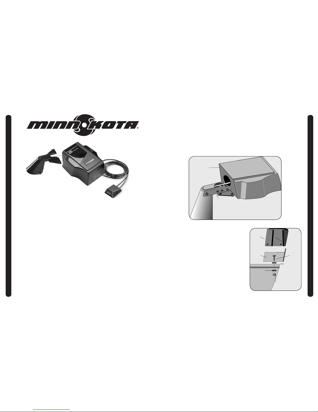
A. Winch and Davit mounted together
1.
Remove DeckHand cover (1) by removing cover screws, items (3) and (4).
2. Place the base (18) and the davit (53) in your desired mounting location. Make sure that when
the DeckHand is operating or in a stowed position, the anchor does not come in contact with the
boat.
3. Make sure there are no obstructions under the mounting surface prior to drilling. Mark at
least 4 of the 6 pre-drilled bolt hole location provided in your base for drilling. Also mark all 4 predrilled bolt hole locations provided in your davit for drilling. Drill through the marked holes in the
base using a
21
/64”
drill bit, and through the marked holes in the davit using
17
/64”
drill bit.
3”
75 mm
cover
base
bolt
rubber washer
flat washer
rondelle
plate
nut
INSTRUCTIONS
OWNER’S MANUAL
Model:
DH 25R
DeckHand
™
Description
Cover DH-25R
Pig Ring
Screw-#8-18x 1-1/2 Stallgrd (2 .ea)
Screw-#8-18x3/4 Stallgrd (2 .ea)
Motor Assembly - DeckHand- Includes 6-13
Shrink Tube 1/4x1-3/4 (2 .ea)
Gear
Washer - Nylatron (3 .ea)
Washer - Steel (3 .ea)
Cover- Housing
Gasket
Screw - 10-32x.375 (4.ea)
Retaining Ring
Screw-#10-32x1/2 (3 .ea)
Washer- Lock Star #10 Ext Tooth 3.ea)
Spool includes 60’ rope
Bearing-Spool
E-Ring 3/8 Dia Shaft
Base- Mounting E-Coat
Switch-Momentary Anchor
Screw-#4-40x3/4 PPH (2 .ea)
Nut-Con/Mom Swt Anchor (2 .ea)
Spring-Anchor
Grommet-Anchor Cover Short (2 .ea)
Grommet-Anchor Cover Long (2 .ea)
Wire- Routing Clip (2 .ea)
Bag Assembly (includes 26-30)
Bolt- Mounting 3500 w/stallgd (4 .ea)
Mounting Washer-Rubber (6 .ea)
Washer 5/16 STD SS (4 .ea)
Nut 5/16 (4 .ea)
Screw, #8
Switch-Control Anchor
Switch Housing (DH- 25R)
Switch Plate
Screw-Switch Plate 6-20x1/2 (3 .ea)
Control Wire (DH-25R)
Leadwire (DH- 25R)
Rope Guide
Spring-Rope Guide
Washer- Eye Shaft (2 .ea)
Cotter Pin 3/32x3/4 (2 .ea)
Circuit Breaker
Tubing- Heat Shrink
Connecting Cable 14ga
Davit Assembly
Large Roller Assembly
Small Roller Assembly
Sleeve Roller Assembly
Safety Chain Assembly
Anchor Shackle
Safety Pin Assembly
Mounting Bolts and Nuts (4 each)
Item Part
1 2370209
2 2303005
3 2372121
4 2372111
n 2377803
6 2375400
8 350-154
9 990-077
10 990-075
11 410-015
11a 337-015
12 830-036
13 788-030
14 2223455
14a 2261718
15 2377900
16 2370000
17 2263010
18 2371900
19 2374010
20 2372130
21 2373100
22 2372700
23 2372900
24 2372910
25 2376300
n 2994803
26 2153501
27 2301720
29 2151726
30 2153100
34 2372100
39 2374000
40 2376500
41 2376510
42 2372150
43 2370700
44 2370602
45 2371610
46 2372710
47 2151700
48 2372615
49 2378204
50 2372031
52 2371412
53 2998411
54 2992312
55 2992306
56 2991503
57 2370820
57a 2370806
58 2992620
59 2774805
PARTS
LIST
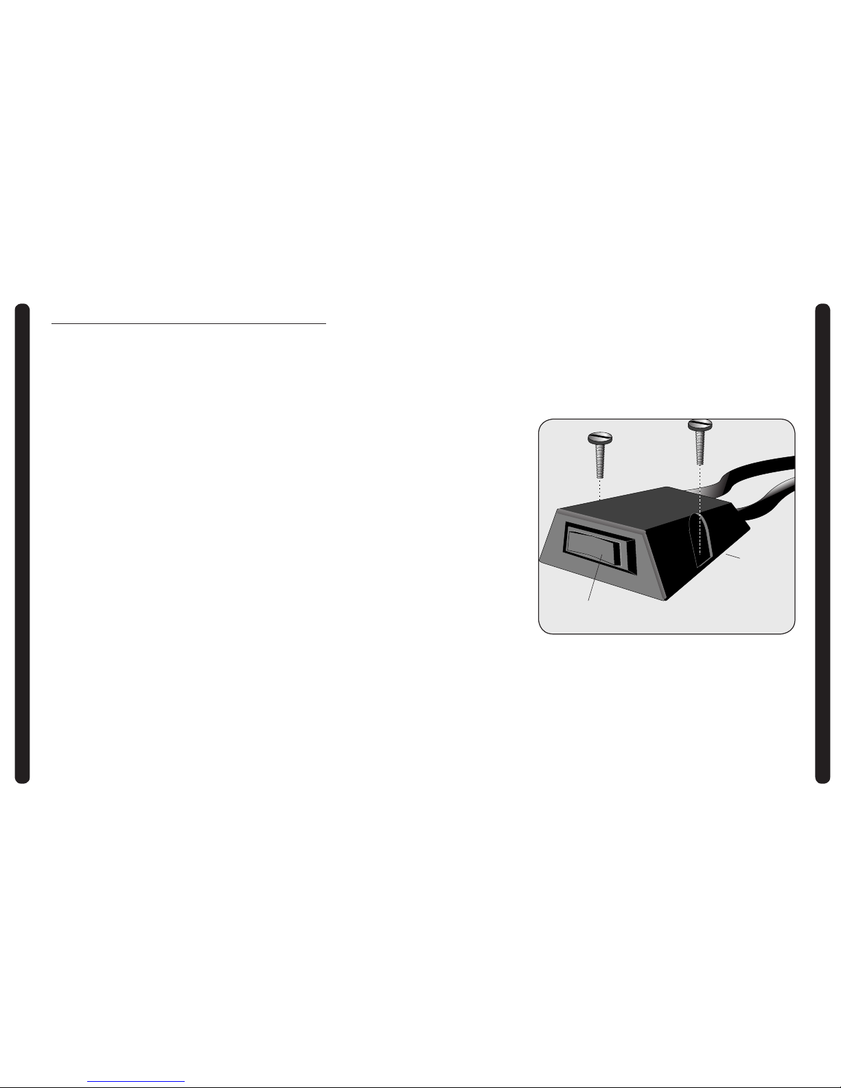
SWITCH INSTALLATION
U
P
O
F
F
D
O
W
N
Switch housing
Switch -center in “OFF” position before battery hook-up.
SWITCH INSTALLATION
Your DeckHand control switch assembly (39) is equipped with an eighteen foot control wire,
allowing convenient mounting almost anywhere in the boat.
1. Select a control switch mounting location. If wire routing or control switch mounting requires
disconnecting of wires within switch housing (40), take special care to insure that proper
reassembly is achieved- refer to wire diagram on page 11.
2. Securely attach switch housing assembly with the two screws (34) provided.
 Loading...