

MINN KOTA 1866160 Owner's Manual
COPILOT ACCESSORY
FOR TERROVA
OWNER'S MANUAL

INTRODUCTION
THANK YOU
ank you for choosing Minn Kota. We believe that you should spend more time fishing and less time positioning your boat.
Th
That’s why we build the smartest, toughest, most intuitive marine products on the water. Every aspect of a Minn Kota product
is thought out and rethought until it’s good enough to bear our name. Countless hours of research and testing provide you the
advantages of a Minn Kota product that can truly take you “Anywhere. Anytime. “ We don’t believe in shortcuts. We are Minn
Kota. And we are never done helping you catch more fish.
REGISTRATION
Re
member to keep your receipt and immediately register
your product. A registration card is included with your product
or you can complete registration on our website.
SERIAL NUMBER
Your Minn Kota 11-character serial number is very important. It
helps to determine the specific model and year of
manufacture. When contacting Consumer Service or
registering your product, you will need to know your product’s
serial number. We recommend that you write the serial
number down so that you have it available for future
reference.
Made by Minn Kota
Johnson Outdoors
CoPilot System
MODEL 1866100
SER NO R365 MK12345
EXAMPLE
Legacy Terrova
mfg. 2016 or prior
Terrova
mfg. 2017
and after
NOTE: The serial number on your CoPilot is located on a label inside your product package. We recommend placing the label on the
inside of the Sideplate for models manufactured in 2017. Motors manufactured in 2017 have a serial number that begins with the
letter R. Serial Numbers starting with a letter before R in the alphabet were manufactured prior to 2017. For models manufactured in
2016 or prior, place the serial number on the plastic cover inside the sideplate once installation in complete. You may also store your
serial number label in a secure location.
Please thoroughly read this user manual. Follow all instructions and heed all safety and cautionary notices. Use of this product
is only permitted for persons that have read and understood these user instructions. Minors may use this accessory only under
adult supervision.

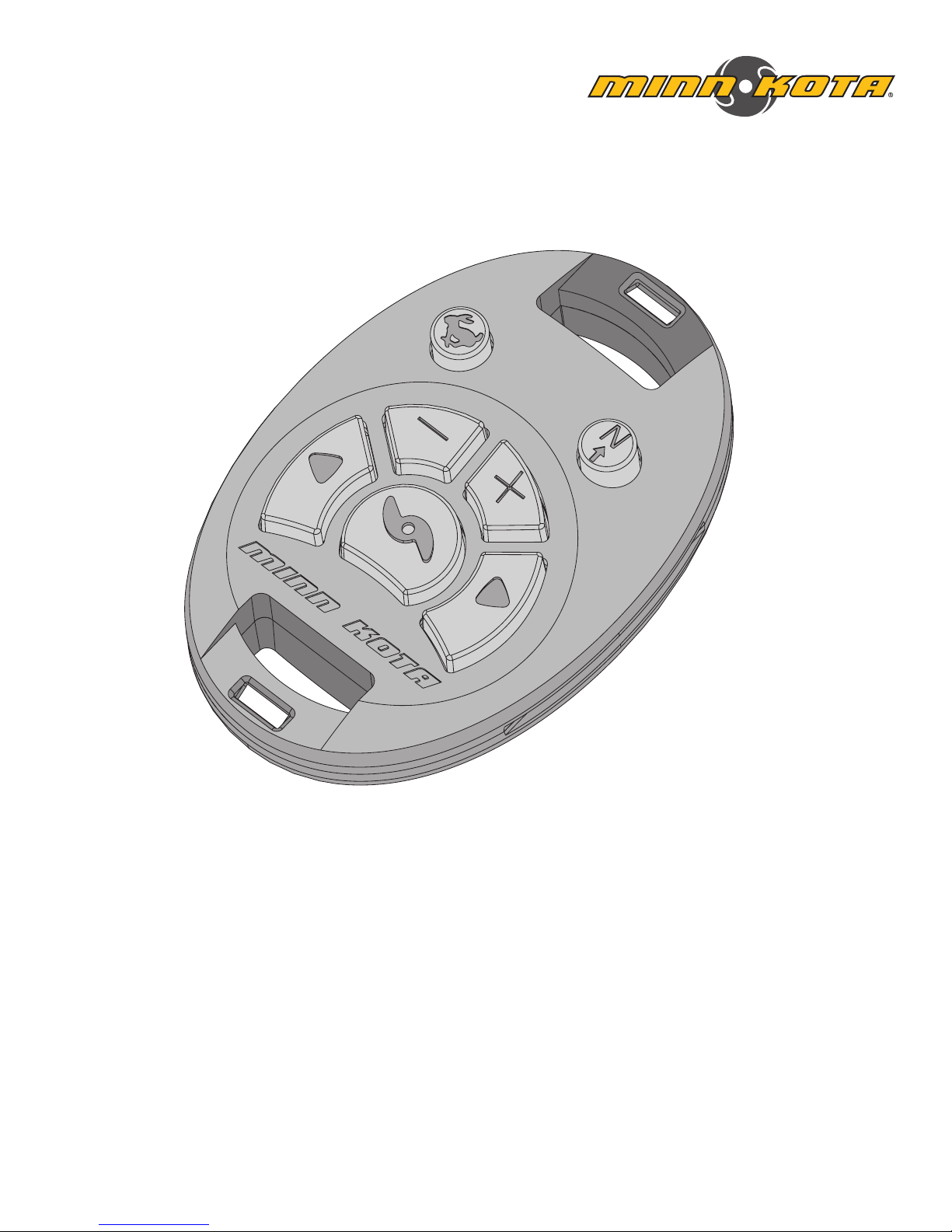
FEATURES
High Speed Bypass
Decrease Speed
AutoPilot ON/OFF
Increase Speed
Steer Left
CoPilot Remote
Steer Right
Prop ON/OFF
Power Connection
Learn Button
NOTE: Specifications subject to change without notice. This diagram is for reference only and may differ from
your actual motor.
CoPilot Receiver
Antenna
INSTALLATION
INSTALLING THE COPILOT
Made by Minn Kota
Johnson Outdoors
TERROVA 55-54"_BT
MODEL 1358803
SER NO R365 MK12345
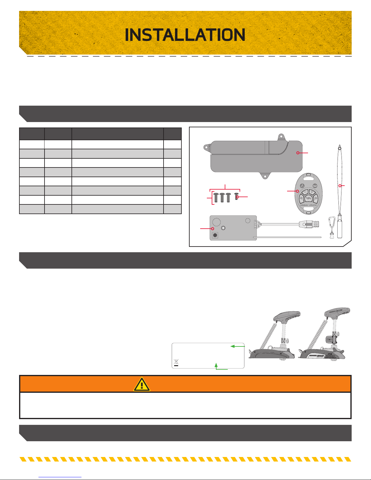
ur new CoPilot accessory comes with everything you’ll need to directly install it on your trolling motor. These instructions are
Yo
intended to show how to install your CoPilot into the Terrova. Please review the parts list, mounting considerations and tools
needed for installation prior to getting started.
INSTALLATION PARTS LIST
Item /
Assembly
A
B 2374197 PCB Y COPLT REC.TERROVA 1
C 2994865 BAG SY PD PRO CO-PILOT 1
1 2370220 COVER,CO-PILOT,FW 1
2 2390801 NYARD, REMOTE, I PILOT 1
3 2301310 SCREW-#8-18 X 1/2 (SS)* 3
4 2332103 SCREW-#6-20 X 3/8 THD*(SS) 1
p
✖ This part is included in an assembly and cannot be ordered individually.
p Not shown on Parts Diagram.
Part # Description Qty.
2994095
2377121 MANUAL-COPILOT,TERROVA 1
TRANSMITTER ASY,TRRV CPLT
1
1
C
3
B
4
A
MOUNTING CONSIDERATIONS
Installing the CoPilot Receiver Based on Manufacture Year
This remote is compatible with Terrova and Legacy Terrova motors. Installation instructions vary depending on the year your motor
was manufactured. Before installing the CoPilot Receiver, determine which year your motor was manufactured. Minn Kota recommends
looking at the trolling motor serial number to determine the year of manufacture. Review the "INTRODUCTION" of your trolling motor manual
to determine the location of your serial number. Motors manufactured in 2017 have a serial number that begins
with the letter R. Serial Numbers starting with a letter before R in the alphabet were manufactured prior to
2017. Motors manufactured in 2017 will also have a model name on the serial number tag that includes "BT".
Be sure to follow the correct Installation Instructions and proceed to either the"Installing the CoPilot
Receiver for Motors Manufactured 2016 or Prior" section of
this manual or " Installing the CoPilot Receiver for Motors
Manufactured 2017 or After".
EXAMPLE
Legacy Terrova
mfg. 2016 or prior
mfg. 2017 or after
Terrova
2
We recommend installing your CoPilot while the boat is on your trailer in a stable position. The motor should be secured and
disconnected from a power source before beginning installation.
TOOLS AND RESOURCES REQUIRED
• #1 Phillips Screw Driver • #2 Phillips Screw Driver
WARNING
INSTALLATION
INSTALLATION
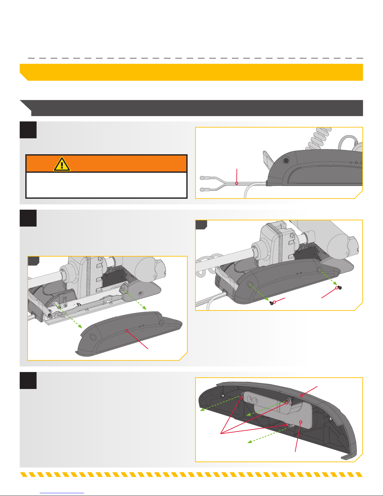
Installing the CoPilot Receiver for Motors Manufactured 2016 or Prior
NOTE: Please verify the year your motor was manufactured before beginning. See page 6 for details.
1
a. Make sure that the Power Cables from the
battery are disconnected, or that the breaker,
if equipped, is "off".
WARNING
Make sure the motor is mounted on a secure, level surface
and is not connected to a power source.
2
b. Using a #2 Phillips Screwdriver, remove the two
Screws from the Right Sideplate that secure it to
the Mount.
c. Remove the Right Sideplate.
2c
Power Cables
2b
Sideplate Screw
3
d. Turn the Right Sideplate over. On the back side
of the Right Sideplate, remove the three screws
holding the CoPilot Cover in place using a #2
Phillips Screwdriver.
Right Sideplate
Right Sideplate
Screws
CoPilot Cover
INSTALLATION
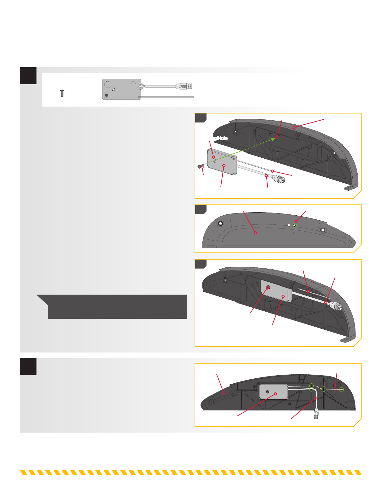
4
ITEM(S) NEEDED
#4 x 1 #B x 1
e. With the CoPilot Cover removed, take the CoPilot
Receiver (Item #B) and position it in the space
below where the CoPilot Cover was attached.
f. Position the CoPilot Receiver so that the Learn
Button is positioned towards the upper left of
the sideplate. The Antenna and CoPilot Power
Connection should sit to the right and exit the
board from the surface that sits towards the
Right Sideplate. The Mounting Hole in the
CoPilot Receiver should sit on the left Screw Peg
on the sideplate.
g. Check the placement of the CoPilot Receiver by
making sure that the Learn Button is visible when
the Right Sideplate is turned over.
h. Using the #6-20 X 3/8’’ Screw (Item #4)
provided, insert the Screw through the receiver
and into the Right Sideplate. Be sure that
the wires are not pinched in the Screw Pegs
when tightening the Screw using a #1 Phillips
Screwdriver. Do not over tighten.
4e
Mounting Hole
Screw
CoPilot Receiver
4g
Right Sideplate
4h
Screw Peg
Power Connection
Right Sideplate
Antenna
Learn Button
Antenna
Power Connection
5
NOTE: Do not over tighten the Screw that
holds the CoPilot Receiver in place.
i. With the Right Sideplate laying flat, and the
CoPilot Receiver that was just installed facing
upwards, route the yellow wire Antenna through
the pegs and grooves on the Right Sideplate.
Follow the grooves in each of the pegs.
j. Route the Power Connection through the bottom
groove in the Right Sideplate.
Right Sideplate
CoPilot Receiver
Screw
CoPilot Receiver
Antenna
Power Connection
INSTALLATION
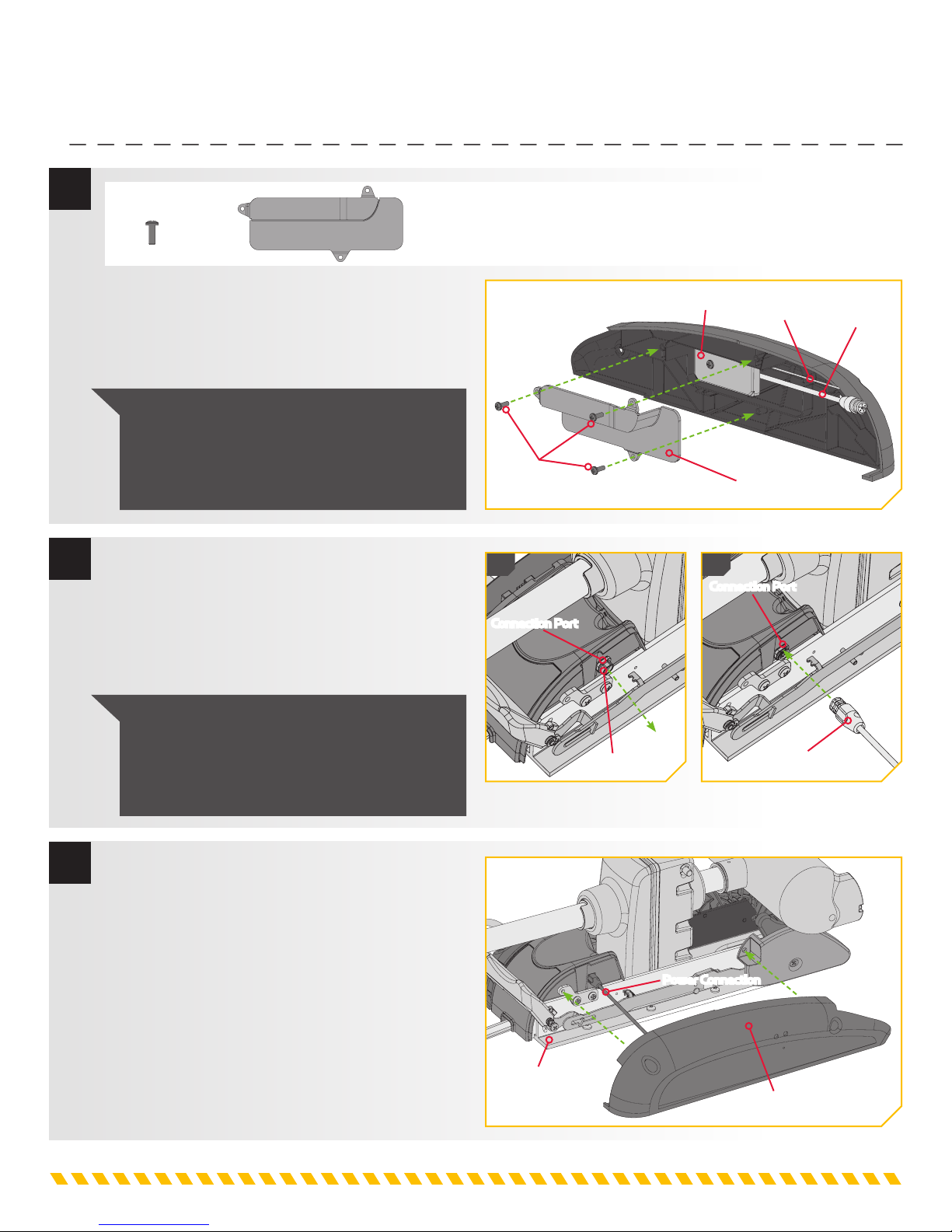
6
7
ITEM(S) NEEDED
#3 x 3 #1 x 1
k. Take the new CoPilot Cover (Item #1) and place it
over the CoPilot Reveiver that was just installed.
Attach the CoPilot Cover to the Right Sideplate
with the three 8-18 X 1/2 Screws (Item #3) using
a #2 Phillips Screwdriver.
NOTE: The old CoPilot Cover that was removed
at the beginning of the installation will no longer
fit on the Right Sideplate. This helps to make
sure that the new CoPilot Cover is installed in
case of an accidental mix-up.
l. Remove the Dust Cap from the Connection Port
located towards the back end of the exposed side
of the motor on the right side of the Mount.
m. Take the Power Connection that comes off of the
CoPilot Receiver, which is attached to the Right
Sideplate and plug it into the Connection Port.
CoPilot Receiver
Screws
7l 7m
Connection Port
Connection Port
Antenna
CoPilot Cover
Power
Connection
8
NOTE: Do not apply lubricant or any type of
grease to trolling motor connectors. Make sure
that the flat sides of the Power Connection and
Connection Port align so the plugs connect
together correctly.
n. Be sure that the Power Connection sits
comfortably between the Mount and the Right
Sideplate and cannot be pinched.
o. Reseat the Right Sideplate.
Mount
Dust Cap
Power Connection
Power Connection
Right Sideplate
 Loading...