

Page 1
TM
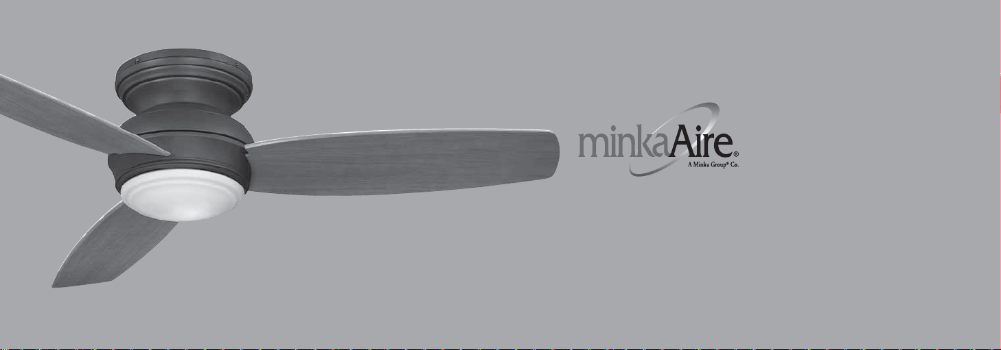
TRADITIONAL CONCEPT
BY
INSTRUCTION MANUAL WARRANTY CERTIFICATE
Page 2

Manual design and all elements of manual design are protected by U.S. Federal and/or State Law, including Patent, Trademark and/or Copyright laws.
Page 3

Minka-Aire® warrants to the original owner that this fan will be free from defects in material and workmanship for one
year from the date of purchase, excluding the motor. Minka-Aire
®
warrants to the original owner that the motor in this fan
shall be free from defects in material and workmanship for as long as the original purchaser owns the fan, and it remains in
This is a limited warranty. Minka-Aire's
Minka-Aire's
®
sole discretion without charge to the original owner, of the fan once Minka-Aire® confirms that the fan has a defect covered by this
limited warranty.
Call our customer service department at 1-800-307-3267 to obtain the name of the Minka-Aire
contact us through our web site, www.minkagroup.net and write to: Ask Mr. Minka if you have any questions or require further assistance.
To obtain warranty service, the owner should return the fan along with proof of purchase to a Minka-Aire
authorized dealer shall then, at its sole discretion: repair the fan, replace the fan, refund the purchase price less the amount directly attributable to the
consumer's prior usage of the fan, or if necessary instruct the consumer to contact Minka-Aire
responsible for the cost of any repair, or replacement for any warranty service provided by a Minka-Aire
You may also at your preference obtain warranty service by returning the fan directly to Minka-Aire
return address, and a description of the claimed product defect. Pack carefully; damage sustained in return transit to Minka-Aire
the original installation.
®
only obligation under this limited warranty is to replace or repair, or refund the purchase price, in
®
authorized dealer closest to your location, or
®
authorized dealer. The Minka-Aire
®
directly for warranty service. Minka-Aire® will be
®
authorized dealer for product under warranty.
®
along with proof of purchase, your name and
®
will be the original
owner's responsibility. Original owner shall be responsible to pay all shipping charges. To obtain warranty service, you may return a fan that proves to
be defective during the warranty period to the following address:
Minka-Aire
®
- Warranty Service, 1151 W. Bradford Court, Corona, CA 92882
®
Page 4

This warranty shall not apply to fans which have been damaged in any way, including improper installation, damage as a result of the removal
of the fan from the origial installation, or damage in shipping. This warranty shall not apply to fans which have been subjected to use for which the
fan was not designed. The purchaser of the fan shall be responsible for any cost of removing the old fan, installing a new fan, or any other costs.
This limited warranty is in lieu of all other express warranties. This limited warranty excludes all incidental and consequential damages, and
Minka-Aire
®
shall not under any circumstances be liable for incidental or consequential damages. Some States do not allow the exclusion of or
limitation of incidental or consequential damages, so the foregoing limitation or exclusion may not apply to you.
This warranty gives you specific legal rights, and you may also have other rights which vary from State to State. We encourage you to promptly
complete and return the enclosed warranty registration card. However, return of the warranty registration card is not a condition of this warranty.
Date Purchased Store Purchased Model Number Serial Number
F594
Page 5

SAFETY RULES............................................................................................
PACKAGE CONTENTS............................................................................
INSTALLING THE MOUNTING BRACKET.....................................
ELECTRICAL CONNECTIONS..............................................................
INSTALLING THE WALL TRANSMITTER.......................................
FINISHING THE INSTALLATION.......................................................
BLADE INSTALLATION..........................................................................
1151 W. Bradford Court, Corona, CA 92882 For Customer Assistance Call: 1-800-307-3267
INSTALLING THE LIGHT KIT MOUNTING PLATE .....................
1
INSTALLING THE LIGHT PLATE..........................................................
2
INSTALLING THE LIGHT BULB AND GLASS SHADE .............
3
OPERATING THE REMOTE CONTROL/WALL CONTROL .....
4
CARE OF YOUR FAN.............................................................................
5
TROUBLESHOOTING...........................................................................
6
SPECIFICATIONS....................................................................................
7
8
CONTENTS
9
10
11
12
13
14
Page 6
1
Be cautious!
Caution:
SAFETY RULES
1. Before you begin installing the fan, shut power off at the circuit breaker of the fuse box.
2. Be cautious!
3. Make sure that all electrical connections comply with local codes, ordinances, or National Electrical Codes. Hire a qualified electrician or consult a
do-it-yourself wiring handbook if you are unfamiliar with installing electrical wiring.
4. Make sure the installation site you choose allows the fan blades to rotate without any obstructions. Allow a minimum clearance of 7 feet from the
floor and 18 inches from the tip of the blades to the wall.
5. If you are mounting the fan to a ceiling fan outlet box, use a U.L. Listed metal octagonal outlet box marked "Acceptable for Fan Support". Secure
the box directly to the building structure. The outlet box and its support must be able to support the moving weight of the fan (at least 50
pounds) Do not use a plastic box.
6. Caution:
7. If you are mounting the fan to a joist, make sure it is able to support the moving weight of the fan (at least 50 pounds).
8. After you install the fan, make sure that all mounting components are secured to prevent the fan from falling.
9. Do not insert anything into the fan blades while the fan is operating.
10. Turn the fan off and wait for the blades to stop completely before proceeding with maintenance or cleaning.
Read all instructions and safety information before installing your new fan. Review accompanying assembly diagrams.
To reduce the risk of injury use only the screws provided with the outlet box in conjunction with the lock washers provided with the fan.
SUITABLE FOR USE IN
WET LOCATIONS
Page 7

WARNING
NOTE:
NOTE:
NOTE:
The important safeguards and instructions appearing in this manual are not meant to cover all possible conditions and situations that may
occur. It must be understood that common sense, caution and care are factors which can not be built into this product. These factors must be
supplied by the person(s) installing, caring for and operating the unit.
NOTE:
READ AND SAVE ALL INSTRUCTIONS!
WARNING
TO REDUCE THE RISK OF FIRE, ELECTRIC SHOCK OR OTHER PERSONAL INJURY, MOUNT FAN ONLY TO A U.L. LISTED OUTLET BOX OR
SUPPORTING SYSTEM MARKED ACCEPTABLE FOR FAN SUPPORT AND USE MOUNTING SCREWS PROVIDED WITH THE OUTLET BOX IN
CONJUCTION WITH THE LOCK WASHERS PROVIDED WITH THE FAN. MOST OUTLET BOXES COMMONLY USED FOR FAN SUPPORT OF
LIGHTING FIXTURES ARE NOT ACCEPTABLE FOR FAN SUPPORT AND NEED TO BE REPLACED. CONSULT A QUALIFIED ELECTRICIAN IF IN DOUBT.
TO REDUCE THE RISK OF PERSONAL INJURY, DO NOT BEND THE BLADE HOLDERS WHILE INSTALLING, BALANCING THE BLADES OR CLEANING
TO REDUCE THE RISK OF FIRE OR ELECTRONIC SHOCK, THIS FAN ONLY CAN USE UC7067RC SOLID-STATE SPEED CONTROL WITH UC9040T
THE FAN. DO NOT INSERT FOREIGN OBJECTS BETWEEN ROTATING FAN BLADES.
WALL CONTROL ONLY.
Page 8
2
PACKAGE CONTENTS
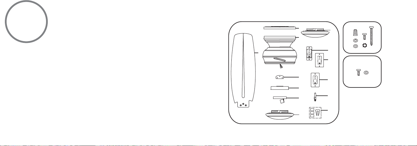
Unpack your fan and check the contents. You should have the following items:
1. Fan Blades (3)
2. Mounting bracket
3. Fan motor/housing ass'y
4. Blade support plates (3)
5. Light kit mounting plate
6. Light plate
7. Glass shade
8. Metal light cover (for optional use)
9a. Wall transmitter Incl. 2 mounting
screws and 3 wire nuts
9b. Wall plate w/2 mounting screws
10. Extra Wall Plate w/2 Mounting
screws
11. 100W Mini-Can halogen bulb
12. Balancing kit
A. Mounting hardware:
#10 x 1.5" Wood screws (2)
#8 x 3/4" Machine screws (2)
Lock washers (2)
4mm star washers (2)
Wire nuts (3)
Washers (2)
B. Blade attachment hardware:
3/16" x 12.3 mm Screws (10)
Rubber washers (10)
2
3
1
4
5
6
7
9a
9b
10
11
12
8
A
B
Page 9
INSTALLING THE MOUNTING BRACKET
WARNING:
REMEMBER
3
Tools Required: Phillips screw driver; slotted screw driver; step-ladder; wire cutters; electrical tape.
WARNING
installation of your new ceiling fan. The use of other parts, hardware or components not supplied by
Minka Aire
REMEMBER
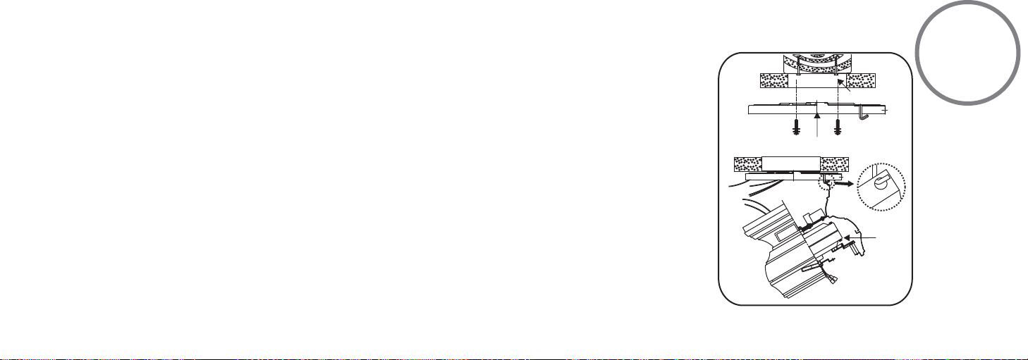
Step 1. Attach the mounting bracket to the outlet box with two screws and washers provided with the
outlet box. Make sure the bracket is tight and secured. (Fig. 1)
Step 2. Lift fan into position by hanging the motor assembly onto the hook from the ceiling mounting
bracket allowing it to hang freely. (Fig. 1)
All of the parts, hardware and components have been provided for your safety and the proper
®
with the fan will void the Minka Aire® Warranty.
to turn off the power. Follow the steps below to hang your fan properly:
OUTLET BOX
MOUNTING BRACKET
MOTOR
FIG. 1
Page 10

4
WARNING:
NOTE:
ELECTRICAL CONNECTIONS
WARNING:
turned off at the main fuse or breaker box before wiring.
NOTE:
The Aire Control® System is equipped with a learning frequency
function which has 256 code combinations to prevent potential
interference from other remote units. The frequency on your Receiver
and Transmitter units have been preset at the factory. (Fig. 2) No
frequency change is necessary, should you desire to install another fan
within the same home or area with a seperate frequency code please see
the "frequency interference" troubleshooting section of this instruction
manual to learn how to change the frequency.
To avoid possible electrical shock be sure electricity is
Step 1 Connect the fan supply (black) wire to the black household supply
wire as shown in Figure 3 & 4.
Step 2. Connect the neutral fan (white) wire to the white neutral
household wire.
Step 3 Connect the fan ground wire (green) to the household ground wire.
Step 4. After all splices are made, check to make sure there are no loose
strands. As an additional precaution we suggest to secure the plastic wire
connectors to the wires with electrical tape.
Page 11
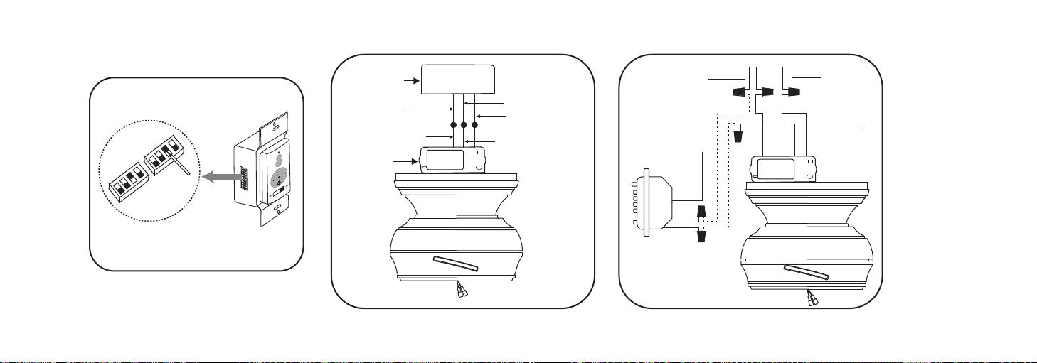
Fig. 2
OUTLET BOX
BLACK (HOT)
BLACK ("AC IN L")
RECEIVER
WHITE (NEUTRAL)
GREEN OR BARE
COPPER (GROUND)
WHITE ("AC IN N")
Fig. 3 Fig. 4
GROUND
WALL
BLACK
CONTROL
BLACK
AC120V
GREEN
BLACK
BLACK
WHITE
GROUNDGREEN
BLACK
INPUT
BLACK
AC SUPPLY
WHITE
Page 12
5
WARNING!
NOTE:
INSTALLING THE WALL TRANSMITTER
WARNING!
ELECTRIC CIRCUIT TO THE TRANSMITTER WALL SWITCH, DAMAGE TO THE
TRANSMITTER WALL SWITCH AND POSSIBLE FIRE COULD OCCUR.
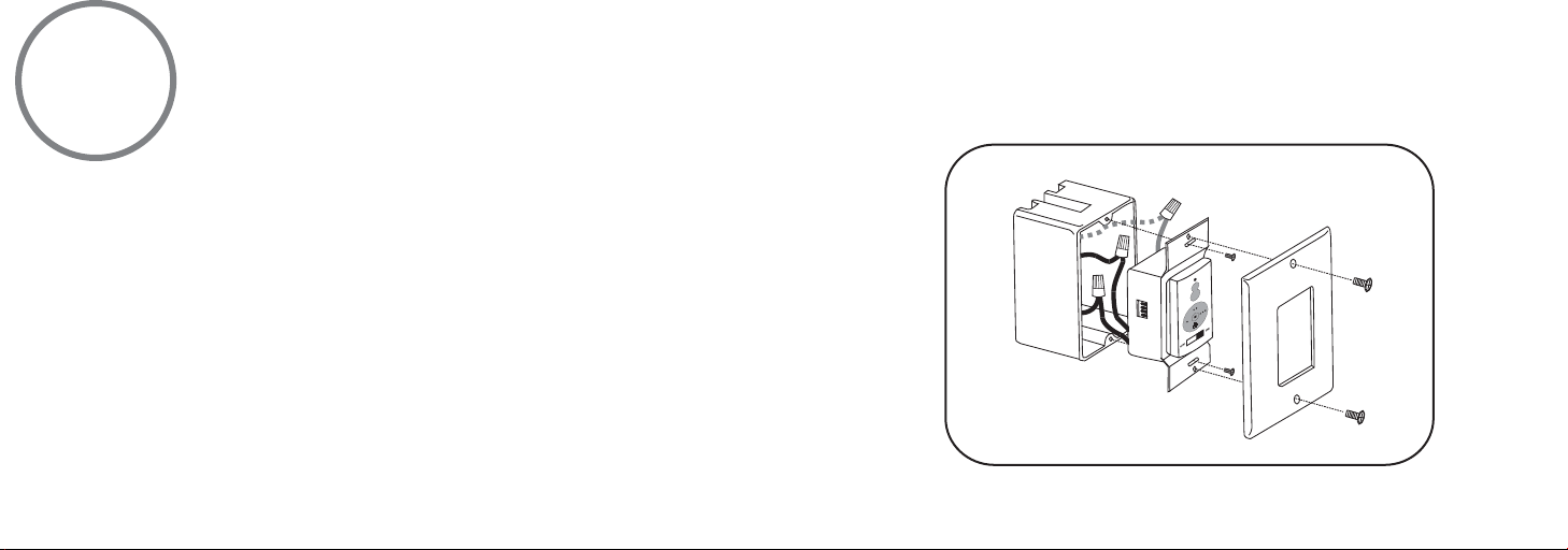
Step 1. Remove the existing wall plate and switch from the wall outlet box.
Step 2. Make the electrical connections as shown in Fig.4. If your outlet box has a ground
wire (Green or Bare Copper) connect the Transmitter's ground wire directly to one of the
screws from the outlet box. Secure all wire connections with the plastic wire nuts provided.
Step 3. Carefully tuck the wire connections inside the outlet box. Use the screws provided
to secure the wall transmitter and wall plate to the outlet box. (Fig. 5)
NOTE:
Your Aire Control™ System includes two sets of face and decorative plate color
options. The wall control comes with standard white faceplate attached. If you desire to
replace it with the Ivory color faceplate included, use a small flat screw driver and gently
pry it apart from the top or bottom of the plate.
HOOK UP "IN SERIES" ONLY. DO NOT CONNECT NEUTRAL SUPPLY WIRE OF
Fig. 5
Page 13
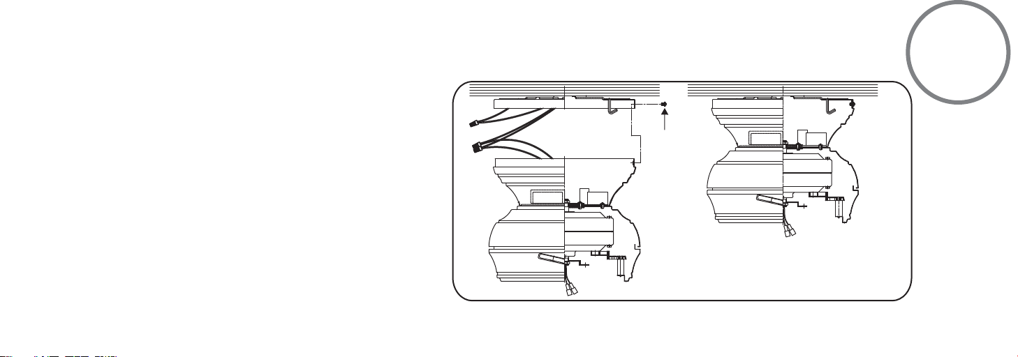
Step 1. Loosen three of the four screws from the motor and
remove the other one.
FINISHING THE INSTALLATION
6
Step 2. Remove the motor assembly from the mounting
bracket hook and engage the key holes to the three screws
previously loosened.
Step 3. Install the screw previously removed and tighten all
four screws.
SCREWS
Fig. 6
Page 14
7
THE FOLLOWING OPERATIONS MUST BE ACCOMPLISHED BEFORE INSTALLING THE LIGHT KIT.
BLADE INSTALLATION
THE FOLLOWING OPERATIONS MUST BE ACCOMPLISHED BEFORE INSTALLING THE LIGHT KIT.
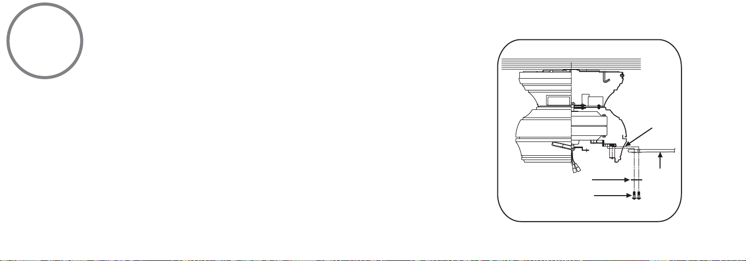
Insert one fan blade into the blade slot on the motor housing and secure with the screws, rubber
washers and blade support plate. Securely tighten screws. Repeat process with other blades. (Fig. 7)
Slots
Blade support plates
Screws with rubber washers
Fig. 7
Blades
Page 15
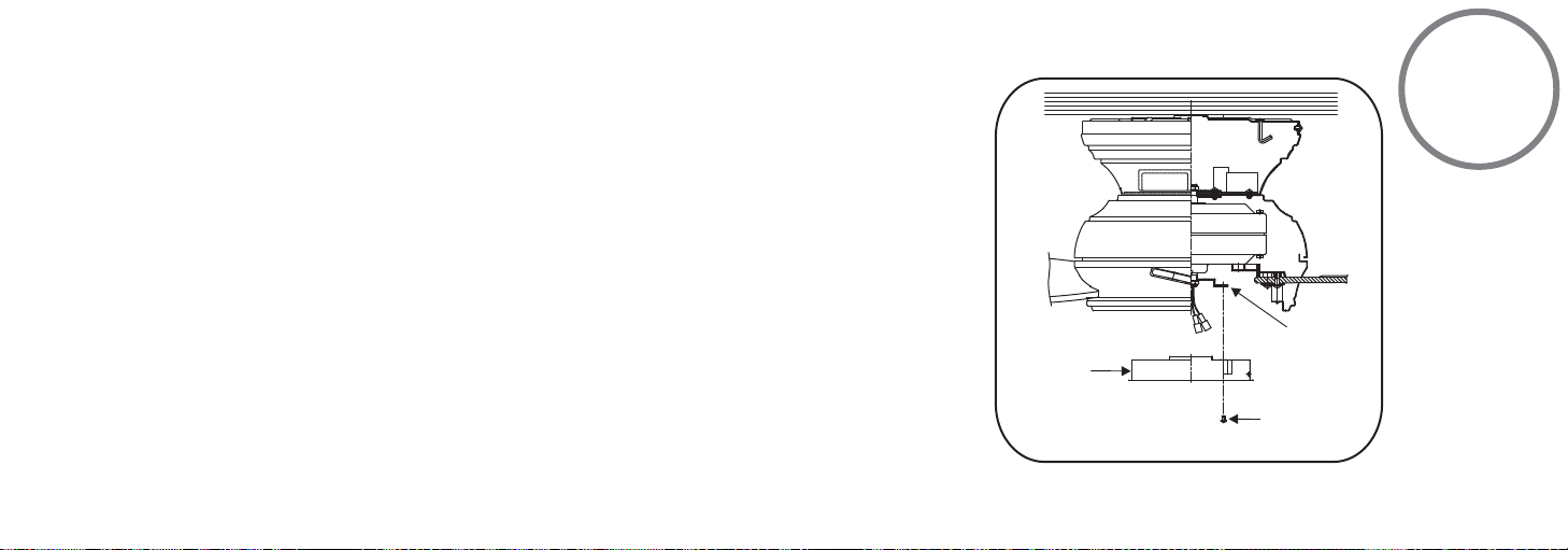
INSTALLING THE LIGHT KIT MOUNTING PLATE
(Do not
remove)
8
Step 1. Remove 1 of 3 screws from the mounting ring and loosen the other 2 screws. (Do not
remove)
Step 2. Place the key holes from the light kit mounting plate over the 2 screws previously
loosened from the mounting ring, turn the light kit mounting plate until it locks in place at the
narrow section of the key holes. Secure by tightening the 2 screws previously loosened and
the one previously removed. (Fig. 8)
LIGHT KIT
MOUNTING
PLATE
Fig. 8
MOUNTING RING
SCREWS
Page 16
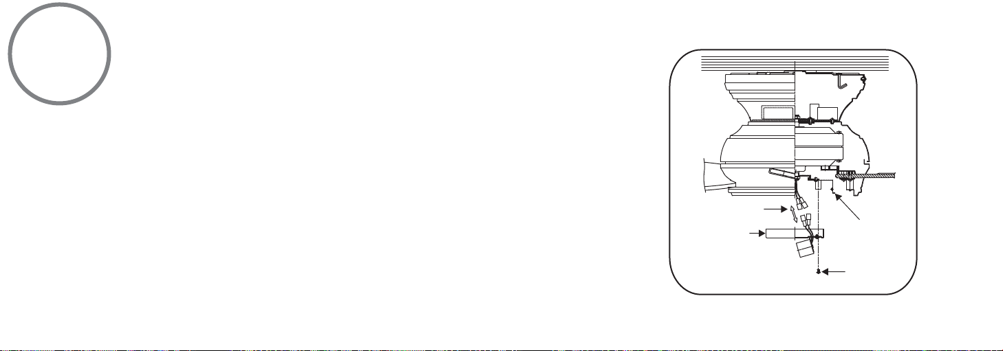
9
NOTE:
(Do not
remove)
INSTALLING THE LIGHT PLATE
NOTE:
1. Remove 1 of 3 screws from the light kit mounting plate and loosen the other 2 screws. (Do not
remove)
2. Raise and hold the light plate close to the light kit mounting plate and proceed to do the wire
connections. Connect the white wire connectors from the light plate and fan, follow the same
procedure with the black wire connectors. (Fig. 9)
3. Place the key holes from the light plate over the 2 screws previously loosened from the light kit
mounting plate, turn light plate until it locks in place at the narrow section of the key holes. Secure
by tightening the 2 screws previously loosened and the one previously removed. (Fig. 9).
Before starting installation, make sure power is turned off at the circuit breaker.
CONNECTORS
LIGHT PLATE
Fig. 9
LIGHT KIT
MOUNTING
PLATE
SCREWS
Page 17
WARNING:
TO REDUCE THE RISK OF
FIRE DO NOT EXCEED MAXIMUM WATTAGE RATING.
DO NOT OVERTIGHTEN.
NOTE:
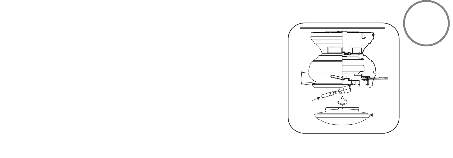
INSTALLING THE LIGHT BULB AND GLASS SHADE
WARNING:
halogen bulb, care should be taken not to touch it with your bare hands. Oil residue will
shorten the life of the halogen bulb. If you accidentally come into contact, wipe thoroughly
with a clean, lint-free, cotton cloth. Allow the bulb to cool off for 10 minutes before changing
the bulb. Use light bulb in accordance with the fan's specification. TO REDUCE THE RISK OF
FIRE DO NOT EXCEED MAXIMUM WATTAGE RATING.
Step 1. Install 1x100W halogen bulb (included).
Shut of the power supply before removing or replacing lamp. In handling of
10
Step 2. Raise glass shade up against bottom of fan housing and secure it to the fan by turning
the glass shade clockwise until snug. DO NOT OVERTIGHTEN.
NOTE:
The metal light cover included with your fan is an option to replace the glass for the
light in the event that you prefer not to use the light feature of your fan. The metal light cover
is not necessary for the light operation; it can be saved for later use if desired.
(Fig. 10)
100 W HALOGEN
BULB
Fig. 10
GLASS
SHADE
Page 18
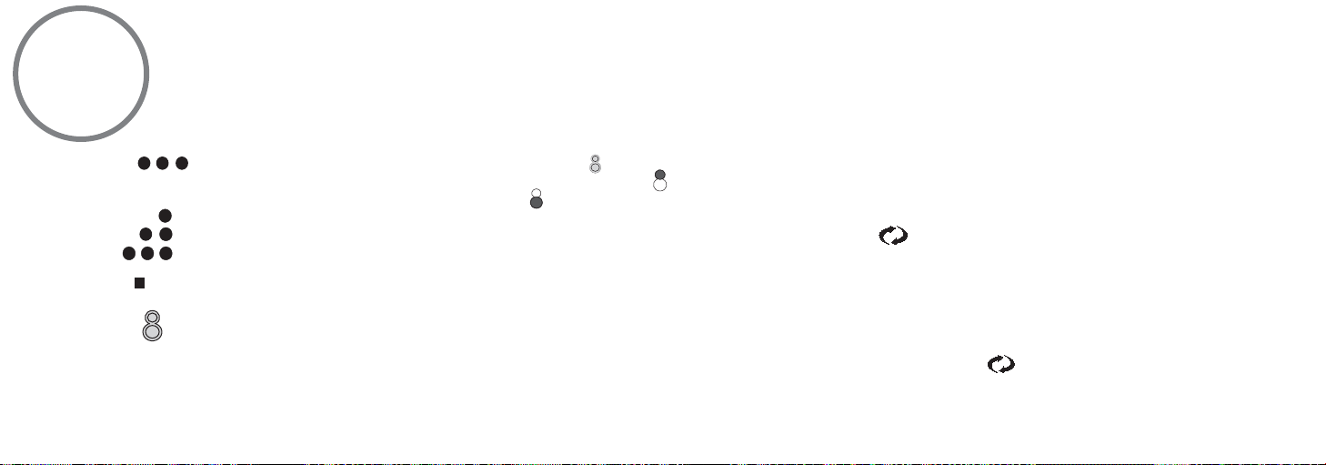
11
NOTE:
Restore Power to Ceiling Fan.
A. Buttons:
These buttons are used to set the fan speeds as
follows;
= Low Speed
= Medium Speed
= High Speed
B. Button:
This button turns the fan off.
C. Button:
These buttons turn the light ON or OFF and also
control the brightness settings of the light. The
following
OPERATING THE REMOTE CONTROL/WALL CONTROL
Remote Control only: Install a A23 12 volt battery (included). To prevent damage to transmitter remove the battery if not used for long periods of time.
instructions apply to ceiling fans that feature a
DOWN light ( button) only or ceiling fans that
feature an UP light ( button) and a DOWN
light ( button) that are controlled independent
of each other.
Press and release the button for the desired
light to turn the light ON or OFF. Press and hold
the button to set the desired light brightness.
The light will cycle between bright and dim
settings as long as the button is pressed. The
light key has an automatic auto-resume feature
that allows the light to remain at the same
brightness as the last time it was turned off.
D. OFF-ON Slide Button (Wall Control Fans
Only)
This button turns the power Off and On to the
Fan and Light(s).
E. " " Button: (Full Function Remote Control
Units Only)
This button is used to change the direction of
the rotation of the blades; forward for warm
weather or reverse for cool weather.
NOTE:
If your Remote Control or Wall Control
does not have a " " button, Please look for a
slide reverse switch on the motor housing.
Page 19
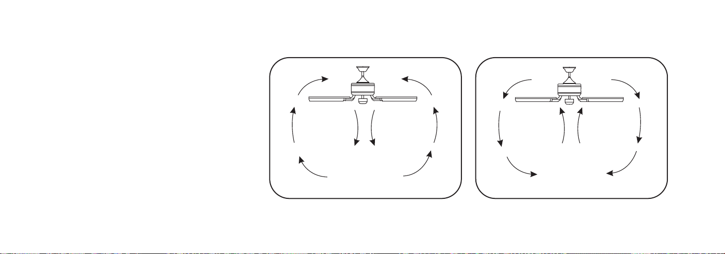
Speed settings for warm or cold weather
NOTE:
depend on factors such as room size, ceiling
height and number of fans.
NOTE:
To change the direction of the rotation of
the blades the fan must be in operation mode.
Warm Weather (forward)
A DOWNWARD airflow creates a cooling effect
as shown in Figure 11. This allows you to set
your air conditioner on a warmer setting
without affecting your comfort.
Cool Weather (Reverse)
An UPWARD airflow moves warmer air off the
ceiling area as shown in Figure 12. This allows
you to set your heating unit on a cooler setting
without affecting your comfort.
Fig. 11
SUMMER OPERATION
WINTER OPERATION
Fig. 12
Page 20

12
WARNING!
CARE OF YOUR FAN
Here are some suggestions to help maintain your fan.
1. Because of the fan's natural movement some connections may
become loose. Check the support connections, brackets and blade
attachments twice a year. Make sure they are secure. (It is not necessary
to remove fan from the ceiling).
2. Clean your fan periodically to help maintain its new appearance over
the years. Use only a soft brush or lint free cloth to avoid scratching the
finish. Plated finishes are sealed with lacquer to minimize discoloration
or tarnishing. Do not use water when cleaning, this could damage the
motor, wood blades or possibly cause an electrical shock.
3. If your fan is provided with wood veneer blades; you can apply a light
coat of furniture polish for additional protection and enhanced beauty.
Cover small scratches with a light application of shoe polish.
4. Use a lint free lightly damp cloth or duster to remove dust from the
blades.
5. There is no need to oil your fan. The motor has permanently lubricated
bearings.
6. If your fan is provided with glass shades, clean with lukewarm soapy
water and a soft cloth or sponge. DO NOT IMMERSE GLASS SHADES IN
HOT WATER. DO NOT PUT GLASS SHADES INTO AN AUTOMATIC
DISHWASHER.
WARNING!
MAKE SURE THE POWER IS OFF AT THE
ELECTRICAL PANEL BOX BEFORE YOU
ATTEMPT ANY REPAIRS. REFER TO THE
SECTION, "ELECTRICAL CONNECTIONS".
Page 21

SYMPTOM
Note:
NOTE:
Fan will not start
SOLUTION
●
Check to make sure the wall switch is
turned on.
●
Check circuit fuses or breakers.
●
Caution! Make sure the power is turned
off before performing the following steps.
Remove canopy and check wire
connections.
●
Check wall control transmitter
connections (if applicable).
●
Fan must be installed at a maximum
Note:
distance of 40 feet from the transmitting
unit for proper signal transmission
between the transmitting unit and the
fan's receiving unit.
SYMPTOM
Fans/Light Turn On
and Off Unexpectedly
SOLUTION
●
This is caused by
interference, change the
code frequency from the
transmitter, and follow
the instructions from
Section 5 again to
operate your transmitter
and fan.
TROUBLESHOOTING
SYMPTOM
Fan Sounds Noisy
SOLUTION SOLUTION
Allow a 24-hour "break in" period.
●
Most noises associated with a
new fan will go away during this
time.
Make sure the screws that attach
●
the fan blade holder to the motor
hub is tight.
Make sure outlet box is secured
●
to building structure, if necessary
use the wood screws provided to
further secure outlet box to joist.
Make sure hanger bracket is
●
secure to the outlet box, screws
are tight.
SYMPTOM
Fan Wobble
●
NOTE:
weight. Because wood and plastic
blades vary in density, the fan may
wobble even though blades are
matched.
●
Make sure outlet box is secured to
building structure, if necessary use the
wood screws provided to further secure
outlet box to joist.
●
Make sure hanger bracket is secure to
the outlet box, screws are tight.
●
Use the balancing kit provided if the
wobble is excessive (follow instructions
included with balancing kit)
13
All blade sets are grouped by
Page 22

SYMPTOM
Note:
Frequency Interference
SOLUTION
1. Turn the power off to your ceiling fan.
2. Please use a small size tool to change the frequency settings on the control system.
3. Return power to the unit.
Note:
After the AC power is on, do not press any other button on the transmitter before pressing the "Stop" button, doing so will cause the
procedure to fail.
4. Within 60 seconds of turning the Fan's AC power ON. Press the transmitter's "Stop" button and hold the "Stop¡" button for 10 seconds.
5. Once the receiver has detected the set frequency, the down light of your fan if applicable will blink twice. (There is no indication if your fan is not
equipped with a light).
6. The receiver has now learn the frequency which has been selected on the transmitter. After completing the steps above, you should be able to
operate the ceiling fan and light. If the fan is not responding to the transmitter, please turn the power off to the receiver, and repeat the process.
Page 23
SPECIFICATIONS
14
These are typical readings. Your actual fan may vary.
They do not include amps and wattage used by the
light(s).
For any additional information about your
Minka Aire Ceiling fan, please write to;
R
1151 W. Bradford Court, Corona, CA 92882 For Customer Assistance Call: 1-800-307-3267
Fan Size
52"
Low
Medium
High
Volts
120
120
120
Amps
0.31
0.43
0.50
WattsSpeed
13.5
32.5
60.5
RPM
59
116
178
CFM
2690
4950
6565.4
N.W.
10.22
kgs
G.W.
11.34
kgs
C.F.
2.30’
 Loading...