

Page 1
Congratulations on your purchase of a Minka-AireTM
ceiling fan! Your new fan will be a beautiful addition
YY RR
Y
W A R RA N T Y
GA RA NT êA DE A„ OS
33
00
0
3
finish, solid designer colors, and unique glass and crystal designs. A
large selection of light fixtures and light kits are also available. Ask
your dealer about accessories that will allow your to customize your
fan.
We're certain that your Minka-AireTM fan will provide you
with many years of comfort, energy savings and satisfaction. To
ensure your personal safety and to maximize the performance of your
fan, please read this manual thoroughly.
to you home, and will keep you comfortable
throughout the year. Minka-AireTM offers a variety
of ceiling fans: combinations of wood and brass
LIMITED 30 YEAR WARRANTY
Minka-Aire
and workmanship for one year from the date of purchase, except for
the motor. Minka-Aire
motor in this fan shall be free from defects in material and
workmanship for 30 years from the date of purchase. Minka-Aire
only obligation under this limited warranty is to replace, repair or
refund the purchase price for any fan confirmed by Minka-Aire
be defective in material or workmanship after such fan is returned to
Minka-Aire
purchase and with shipping charges prepaid. This warranty shall not
apply to fans which have been damaged as a result of improper
installation, removed from the original installation or subjected to
use for which the fan was not designed. The customer shall be
responsible for any cost of removing the old fan, installing a new fan
or any other costs.
This limited 30 year warranty is in lieu of all other expressed
warranties. Minka-AireTM shall under no circumstances be liable for
any incidental or consequential damages.
Date Purchase
Store Purchase
Model Number F581
TM
warrants this fan to be free from defects in material
TM
warrants to the original owner that the
TM
TM
by the original purchaser along with a proof of
TM
ro
Serial Number
Page 2

CONTENTS
SAFETY RULES...................................................................................
PACKAGE CONTENTS.....................................................................
INSTALLING THE FAN....................................................................
HANGING THE FAN........................................................................
ELECTRICAL CONNECTIONS......................................................
INSTALLING THE WALL TRANSMITTER
FINISHING THE INSTALLATION
BLADE INSTALLATION
..................................................................
......................................................
INSTALLING THE LIGHT BULB AND LIGHT CAP
OPERATING THE WALL TRANSMITTER
CARE OF YOUR FAN.................................................................
TROUBLESHOOTING....................................................................
SPECIFICATIONS.............................................................................
.......................................
..............
......................................
10
11
12
13
1
2
3
4
5
6
7
8
9
1151 W. Bradford Court, Corona, CA 92882
C
and Patents 2004, All Rights Reserved
U
R
L
LISTED
E75795
Page 3

1. SAFETY RULES
1. Before you begin installing the fan,
shut power off at the circuit breaker of
the fuse box.
2. Be cautious! Read all instructions
and safety information before installing
your new fan. Review accompanying
assembly diagrams.
3. Make sure that all electrical
connections comply with local codes,
ordinances, or National Electrical
Codes. Hire a qualified electrician or
consult a do-it-yourself wiring
handbook if you are unfamiliar with
installing electrical wiring.
4. Make sure the installation site you
choose allows the fan blades to rotate
without any obstructions. Allow a
minimum clearance of 7 feet from the
floor and 18 inches from the tip of the
blades to the wall.
5. If you are mounting the fan to a
ceiling fan outlet box, use a U.L. Listed
metal octagonal outlet box marked
"Acceptable for Fan Support". Secure
the box directly to the building
structure. The outlet box and its
support must be able to support the
moving weight of the fan (at least 50
pounds) Do not use a plastic box.
6. Caution: To reduce the risk of
injury use only the screws provided
with the outlet box in conjunction
with the lock washers provided with
the fan.
7. If you are mounting the fan to a
joist, make sure it is able to support the
moving weight of the fan (at least 50
pounds).
8. After you install the fan, make sure
that all mounting components are
secured to prevent the fan from falling.
9. Do not insert anything into the fan
blades while the fan is operating.
10. Turn the fan off and wait for the
blades to stop completely before
changing the fan direction.
NOTE: The important safeguards and
instructions appearing in this manual
are not meant to cover all possible
conditions and situations that may
occur. It must be understood that
common sense, caution and care are
factors which can not be built into this
product. These factors must be
supplied by the person (s) installing,
caring for and operating the unit.
WARNING
TO REDUCE THE RISK OF FIRE, ELECTRIC SHOCK OR OTHER PERSONAL INJURY,
MOUNT FAN ONLY TO A U.L. LISTED OUTLET BOX OR SUPPORTING SYSTEM MARKED
ACCEPTABLE FOR FAN SUPPORT AND USE MOUNTING SCREWS PROVIDED WITH THE
OUTLET BOX IN CONJUCTION WITH THE LOCK WASHERS PROVIDED WITH THE FAN.
MOST OUTLET BOXES COMMONLY USED FOR FAN SUPPORT OF LIGHTING FIXTURES
ARE NOT ACCEPTABLE FOR FAN SUPPORT AND NEED TO BE REPLACED. CONSULT A
TO REDUCE THE RISK OF PERSONAL INJURY, DO NOT BEND THE BLADE HOLDERS
WHILE INSTALLING, BALANCING THE BLADES OR CLEANING THE FAN. DO NOT
INSERT FOREIGN OBJECTS BETWEEN ROTATING FAN BLADES.
TO REDUCE THE RISK OF FIRE OR ELECTRIC SHOCK, DO NOT USE THIS WITH ANY
QUALIFIED ELECTRICIAN IF IN DOUBT.
SOLID-STATE SPEED CONTROL DEVICE.
Page 4
PACKAGE CONTENTS 2.
2
1
3
4a
4b
5
6
7
8a
8b
9
10
11
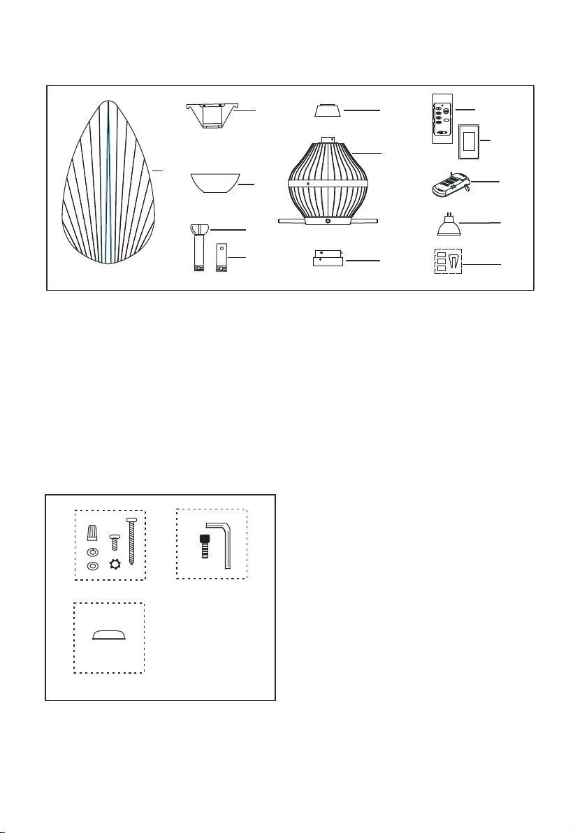
Unpack your fan and check the contents. You should have the following items:
1. Fan blades (4 )
2. Hanger bracket
3. Canopy
4a. Standard downrod assembly
4b. Minimum-length downrod (for
close to ceiling mounting only)
5. Coupling cover
7. Light cap
8a. Wall Transmitter Incl. 2 mounting
screws and 3 wire nuts
8b. Wall plate w/2 mounting screws
9. Receiver with 7 wire nuts
10. 50W MR16 2-pin base halogen bulb
11. Balancing kit
6. Fan motor assembly
A. Mounting Hardware:
#10 X 1.5" Wood Screws (2 PCs.)
#8-32 X 3/4" Machine screws (2PCs.)
Lock washers (2 PCs.)
4mm Star washers (2 PCs.)
A
C
B
Wire nuts (3 PCs. )
Washers (2PCs.)
B. Blade Attachment Hardware:
4 mm Allen wrench
3/16" Allen screws (8PCs.)
C. Downrod Rubber Cover
Page 5
3. INSTALLING THE FAN
Tools Required: Phillips screw driver; slotted screw driver; step-ladder; wire cutters;
electrical tape.
CROS S BR AC E
CEIL IN G
JOIS T
FI G. 1
ANGL ED C EI LING
MAXI MU M 17 AN GLE
RECE SS ED
OUTL ET B OX
FI G. 3
CEIL IN G
JOIS T
OUTL ET B OX
PROV ID E
STRO NG
SUPP OR T
HANG ER
OPEN IN G
MUST B E
FACIN G
UPSI DE
CEIL IN G JO IS T OR
CROS S BR AC E
FI G. 2
HANG ER B AR
(OPT IO NA L)
OUTL ET B OX
FI G. 4
PARALLEL WO OD B RA CE
(Min . 2" T hi ck)
OUTL ET
BOX
CEIL IN G
JOIS T
HANG ER
BRAC KE T
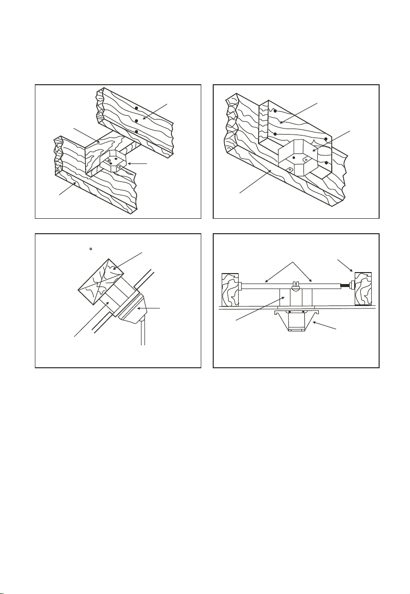
MOUNTING OPTIONS
If there isn't an existing mounting box,
then read the following instructions.
Disconnect the power by removing
fuses or turning off circuit breakers.
Secure the outlet box directly to the
building structure. Use appropriate
fasteners and building materials. The
outlet box and its support must be able
to fully support the moving weight of
the fan (at least 50 lbs.). Use a UL
Listed metal outlet box. Do not use a
plastic outlet box.
Figure 1, 2 and 3 are examples of
different ways to mount the outlet box.
Note:You may need a longer downrod
to maintain proper blade clearance
when installing on a steep, sloped
ceiling. Longer downrods are available
from your
To hang your fan where there is an
existing fixture but no ceiling joist, you
may need to install a hanger bar as
shown in Fig. 4 (available at your
Minka-AireTM dealer).
Minka-AireTM dealer.
Page 6
HANGING THE FAN 4.
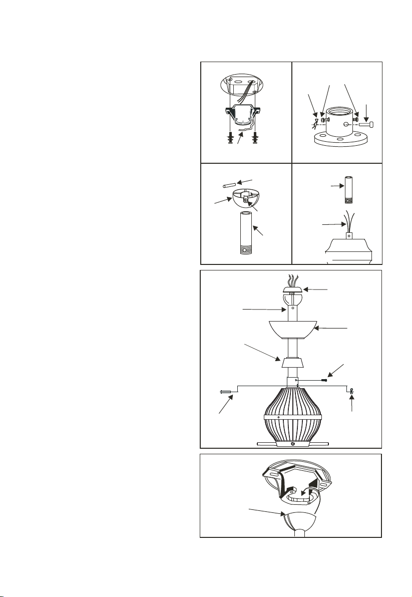
REMEMBER to turn off the power.
Follow the steps below to hang your
fan properly:
Step 1. Secure the hanger bracket to
the ceiling outlet box using screws
included with your outlet box, lock
washers included with the fan. (Fig.5)
Step 2. Loosen the two set screws and
remove the hitch pin and lock pin in
the top coupling of the motor
assembly. (Fig. 6)
Step 3. Remove hanger ball from
downrod assembly by loosening set
screw, removing the cross pin, and
sliding ball off rod. (Fig.7)
Step 4.
Carefully feed fan wires up
through the downrod. (Fig. 8) Thread
Downrod into the Coupling until the
holes are lined up and secure with the
Lock Pin and Hitch Pin previously
removed, tighten Set Screws. (Fig. 9)
Step 5. Slip coupling cover and
canopy onto downrod. (Fig. 9)
Carefully reinstall hanger ball onto
rod being sure that cross pin is in
correct position, set screws are tighten
and wires are not twisted.
Out le t bo x
Hange r br ac ke t
Figu re 5
Cross p in
Hange r
bal l
Dow nr od
Figu re 7
Dow nr od
Cou pl in g
cov er
*Om it coup li ng
cov er w he n
the m in im um -l eng th
dow nr od
usi ng
Screw
Hit ch
pin
Figu re 6
Dow nr od
Sup pl y
wires
Figu re 8
Set
scr ew s
Downrod
rubber cover
Canop y
Set scr ew s
Loc k
pin
Step 6. Place downrod rubber cover
onto the hanger ball, then re-install
the hanger ball onto the downrod
making sure the crosspin is in correct
postion, set screw is tight and wires
are not twisted. (Fig. 9)
Step 7.
Lift the Motor Assembly and
place the Hanger Ball into the Hanger
Bracket. Rotate the Motor Assembly as
needed until the check groove from
the Hanger Ball rests firmly over the
registration tab from the Hanger
Bracket. Motor Assembly should not
rotate if this is done correctly. (Fig. 10)
Loc k pi n
Fig. 9
Regis tr at io n
slot
Figu re 10
Hit ch p in
Page 7
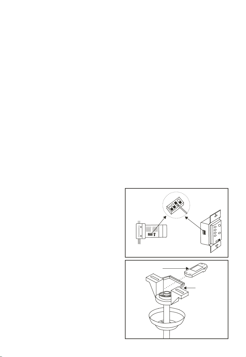
5. ELECTRICAL CONNECTIONS
WARNING: To avoid possible
electrical shock be sure electricity is
turned off at the main fuse or breaker
box before wiring.
NOTE: The Hand Held Remote or
Wall Control units included with your
ceiling fan are equipped with 16 code
combinations to prevent possible
interference from or to other remote
units. The frequency switches on your
Receiver and Transmitter units have
been preset at the factory, please recheck to make sure the switches on
both units are set to the same positions.
The frequency settings should be
changed only in case of interference or
if a second or more remote controlled
ceiling fans are installed in the same
structure. Any code combination will
operate the ceiling fan and light as long
as the Receiver and Transmitter units
are set to the same codes (Fig. 11)
Step 1. Insert Receiver into Hanger
Bracket with the flat side of the
Receiver facing the ceiling. (Fig. 12)
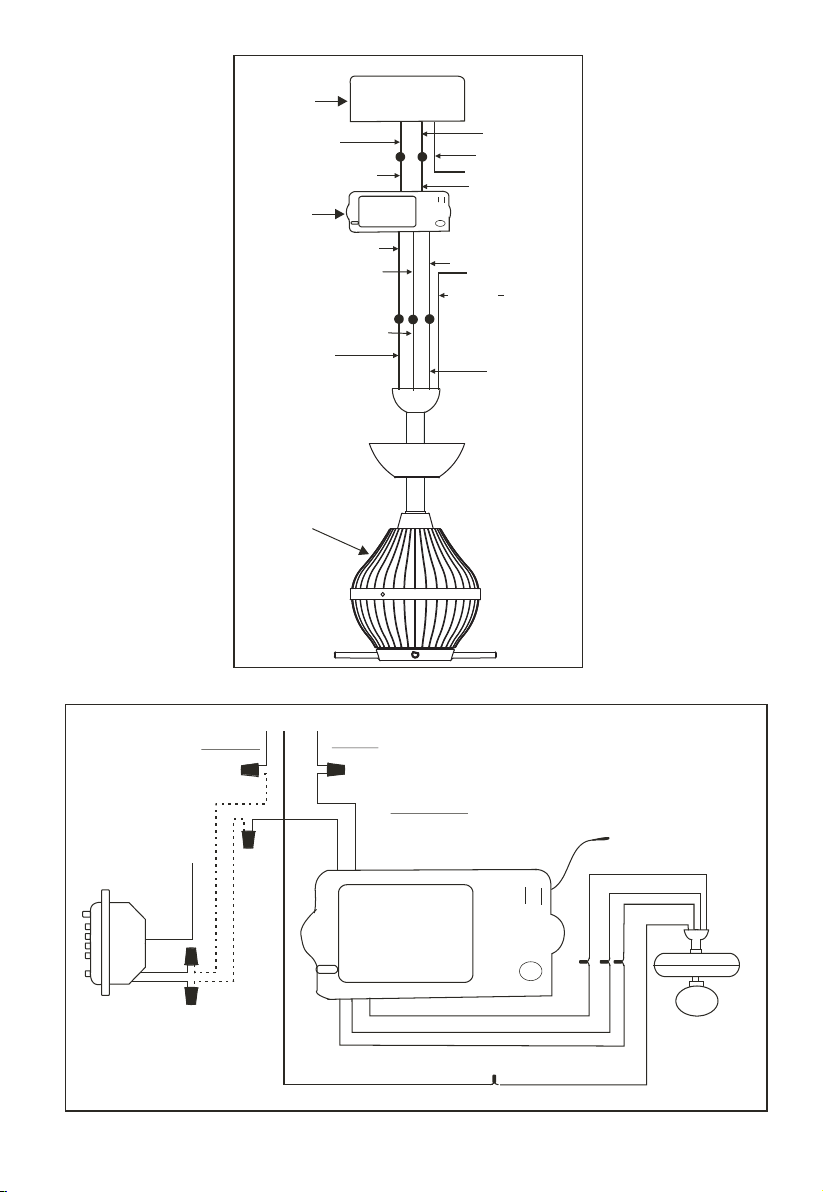
Step 2. Motor to Receiver Electrical
Connections: Connect the WHITE
wire from the fan to the WHITE wire
marked "TO MOTOR N" from the
Receiver. Connect the BLACK wire
from the fan to the BLACK wire
marked "TO MOTOR L" from the
Receiver. Connect the BLUE wire from
the fan to the BLUE wire marked "For
Light" from the Receiver. NOTE: If
your ceiling fan features an UP Light:
Connect the ORANGE wire from the
fan to the ORANGE wire marked "For
Up Light" from the Receiver.
Otherwise disregard this step and
proceed to secure all wire connections
with the plastic wire nuts provided.
(Fig. 13 & 14)
Step 3. Receiver to House Supply Wires
Electrical Connections: Connect the
WHITE wire (Neutral) from the outlet
box to the WHITE wire marked "AC in
N" from the receiver. Connect the
BLACK wire (Hot) from the outlet box
to the BLACK wire marked "AC in L"
from the receiver. Secure all wire
connections with the plastic wire nuts
provided. (Fig. 13 & 14))
Step 4. If your outlet box has a
GROUND wire (Green or Bare Copper)
connect this wire to the Hanger Ball and
Hanger Bracket Ground wires. If your
outlet box does not have a Ground Wire,
then connect the Hanger Ball and
Hanger Bracket Ground Wires together.
Secure wire connection with the plastic
wire nut provided. (Fig. 13 & 14)
After all splices are made, check to make
sure there are no loose strands. As an
additional precaution we suggest to
secure the plastic wire connectors to the
wires with electrical tape.
Fig. 11
Recei ve r
Hange r br ac ke t
Fig. 12
Page 8
Out le t bo x
Bla ck ( ho t)
Bla ck ( "A C IN L ")
Rec ei ve r
Bla ck ( "t o mo to r L")
Blu e (f or l ig ht)
Blu e (f or l ig ht)
Bla ck ( mo to r)
Fan
Fig. 13
Whi te ( ne ut ra l)
Green o r ba re
coppe r (g ro un d)
Whi te ( "A C IN N ")
Whi te ( "t o mo tor N")
(Co nnect t o
Groun d
gro und wir e on
(gr ee n)
han ger bra cket
if no h ouse
gro und wir e
exi sts.)
Whi te ( ne ut ra l)
Fig. 14
Bla ck
INPU T
Whi te
k
c
a
l
B
AC SUPPLY
e
t
i
h
W
Blu e
Bla ck
Whi te
Gro und
Gre en
e
k
t
e
c
i
a
u
h
l
l
W
B
B
AC12 0V
n
k
k
e
c
c
e
a
a
r
l
l
G
B
l
o
l
l
r
t
a
n
W
o
c
B
Gro und
Bla ck
Bla ck
Page 9
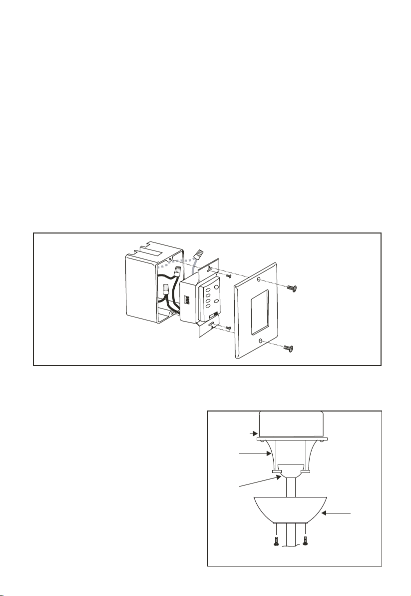
INSTALLING THE WALL TRANSMITTER 6.
WARNING! HOOK UP "IN SERIES" ONLY. DO NOT CONNECT
NEUTRAL SUPPLY WIRE OF ELECTRIC CIRCUIT TO THE
TRANSMITTER WALL SWITCH, DAMAGE TO THE TRANSMITTER
WALL SWITCH AND POSSIBLE FIRE COULD OCCUR.
Step 1. Remove the existing wall plate and switch from the wall outlet box.
Step 2. Make the electrical connections as shown in Fig.14. If your outlet box has
a ground wire (Green or Bare Copper) connect the Transmitter's ground wire
directly to one of the screws from the outlet box . Secure all wire connections
with the plastic wire nuts provided.
Step 3. Carefully tuck the wire connections inside the outlet box. Use the screws
provided to secure the wall transmitter and wall plate to the outlet box. (Fig. 15)
Fig. 15
FINISHING THE INSTALLATION 7.
Step 1. Slide the canopy up to the
ceiling and over the two screws on
hanger bracket. Rotate canopy clockwise
until tight.
Note: adjust the canopy screws as
needed until the canopy is snug. (Fig.
16)
Outle t bo x
Hange r
brack et
Hange r
ball
Fig. 16
Canop y
Page 10
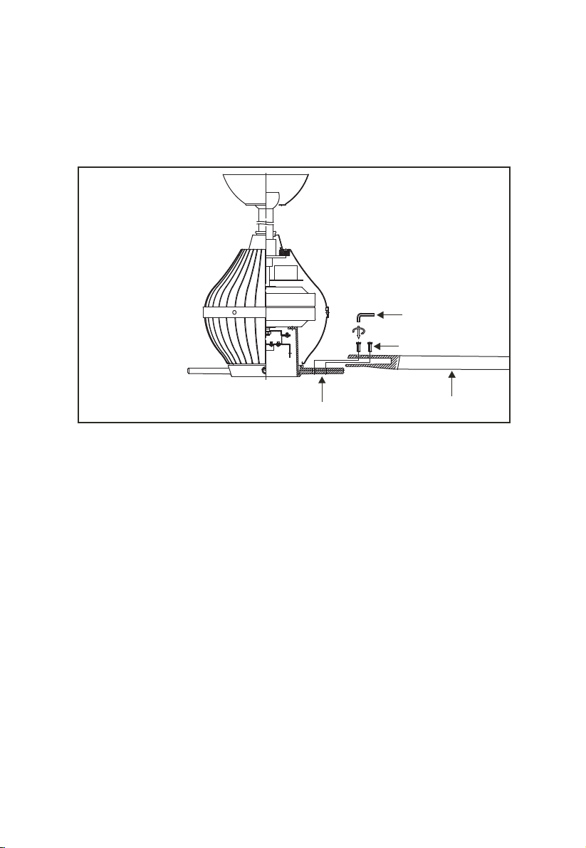
8. BLADE INSTALLATION
1. Insert the blade into the blade holder, align holes from blade to blade holder
and secure with two Allen screws and Allen wrench provided (Fig. 17).
2. Repeat process with the other blades.
Allen wrench
Allen screws
Fig. 17
Blade holder
blades
Page 11
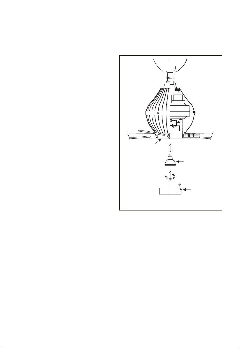
INSTALLING THE LIGHT BULB
& LIGHT CAP 9.
WARNING: Shut of the power
supply before removing or replacing
lamp. In handling of halogen bulb,
care should be taken not to touch it
with your bare hands. Oil residue will
shorten the life of the halogen bulb. If
you accidentally come into contact,
wipe thoroughly with a clean, lint-free,
cotton cloth. Allow the bulb to cool
off for 10 minutes before changing the
bulb. Use light bulb in accordance
with the fan's specification. TO
REDUCE THE RISK OF FIRE DO
NOT EXCEED MAXIMUM
WATTAGE RATING.
Light plate
Step 1. Install 50W MR16 2-pin base
halogen bulb. (Fig. 18).
Step 2. Install the light cap by carefully
turning it clockwise until snug. DO
NOT OVERTIGHTEN. (Fig. 18)
Fig. 18
50 W MR16 2-pin
base
halogen bulb
Light cap
Page 12
10. OPERATING THE REMOTE
CONTROL/WALL CONTROL
Remote Control only: Install a 9 volt battery (not
included). To prevent damage to transmitter
remove the battery if not used for long periods of
time.
Restore Power to Ceiling Fan.
A. HI-MED-LOW Buttons:
These buttons are used to set the fan speeds as
follows;
HI = High Speed
MED = Medium Speed
LOW = Low Speed
B. FAN OFF Button:
This button turns the fan off.
C. LIGHT Button and U/L and D/L Buttons:
These buttons turn the light ON or OFF and also
control the brightness settings of the light. The
following instructions apply to ceiling fans that
feature a DOWN light (LIGHT button) only or
ceiling fans that feature an UP light (U/L button)
and a DOWN light (D/L button) that are
controlled independent of each other;
Press and release the button for the desired light
to turn the light ON or OFF. Press and hold the
button to set the desired light brightness. The
light will cycle between bright and dim settings as
long as the button is pressed. The light key has an
automatic auto-resume feature that allows the
light to remain at the same brightness as the last
time it was turned off.
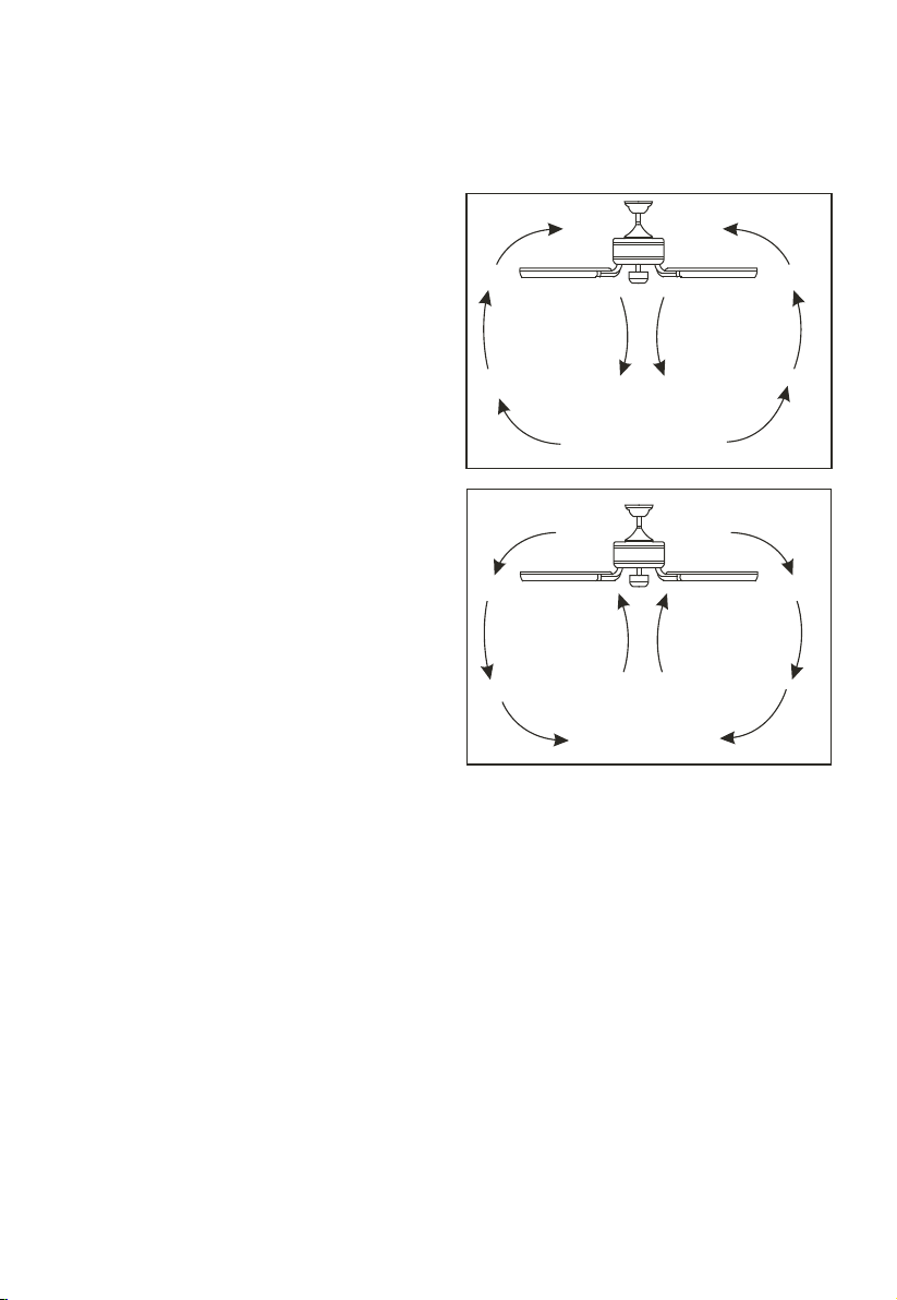
Fig 19
Fig 20
Speed settings for warm or cold weather depend
on factors such as room size, ceiling height and
number of fans.
SUMM ER OP ERATION
WINT ER OP ERATION
D. OFF-ON Slide Button (Wall Control Fans
Only)
This button turns the power Off and On to the
Fan and Light(s).
E. REV Button: (Full Function Remote Control
Units Only)
This button is used to change the direction of the
rotation of the blades; forward for warm weather
or reverse for warm weather.
NOTE: If your Remote Control or Wall Control
does not have a "REV" button, Please look for a
slide reverse switch on the motor housing.
NOTE: to change the direction of the rotation
of the blades the fan must be in operation mode.
Warm Weather (forward)
A DOWNWARD airflow creates a cooling
effect as shown in Figure 19. This allows you to
set your air conditioner on a warmer setting
without affecting your comfort.
Cool Weather (Reverse)
An UPWARD airflow moves warmer air off the
ceiling area as shown in Figure 20. This allows
you to set your heating unit on a cooler setting
without affecting your comfort.
Page 13
CARE OF YOUR FAN 11.
Here are some suggestions to help
maintain your fan.
1. Because of the fan's natural movement
some connections may become loose.
Check the support connections, brackets
and blade attachments twice a year. Make
sure they are secure. (It is not necessary to
remove fan from the ceiling).
2. Clean your fan periodically to help
maintain its new appearance over the
years. Use only a soft brush or lint free
cloth to avoid scratching the finish. Plated
finishes are sealed with lacquer to
minimize discoloration or tarnishing. Do
not use water when cleaning, this could
damage the motor, wood blades or
possibly cause an electrical shock.
3. If your fan is provided with wood veneer
blades; you can apply a light coat of
furniture polish for additional protection
and enhanced beauty. Cover small scratches
with a light application of shoe polish.
4. Use a lint free lightly damp cloth or
duster to remove dust from the blades.
5. There is no need to oil your fan. The
motor has permanently lubricated bearings.
6. If your fan is provided with glass shades,
clean with lukewarm soapy water and a soft
cloth or sponge. DO NOT IMMERSE
GLASS SHADES IN HOT WATER.
DO NOT PUT GLASS SHADES INTO
AN AUTOMATIC DISHWASHER.
WARNING!
Make sure the power is off at the
electrical panel box before you
attempt any repairs. Refer to the
section, "Electrical Connections".
For any additional information about your Ceiling fan, please write to;
1151 W. Bradford Court
Corona, CA 92882
For customer assistance call: 1-800-307-3267
Page 14
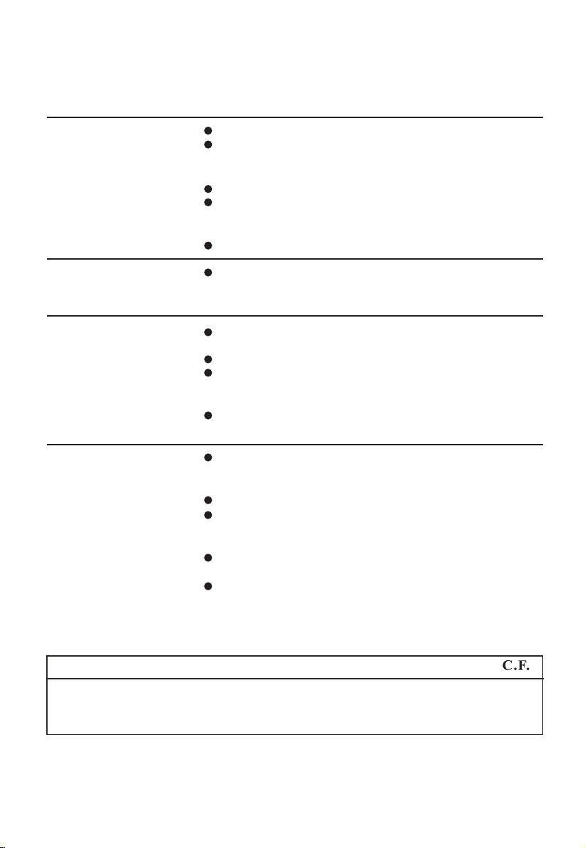
12. TROUBLESHOOTING
Symptoms
Fan Will not Start
Solution
Check to make sure the wall switch is turned on.
Check circuit fuses or breakers.
Caution! Make sure the power is turned off before performing
the following steps;
Remove canopy and check wire connections.
If using a remote controlled fan; check to see that the deep
switches from transmitter and receiver are set to the same
frequency code.
Check wall control transmitter connections (if applicable).
Fans/Light Turn On
and Off Unexpectedly
This is caused by interference, change the code frequency from
the transmitter and receiver. Any code combination will
operate the fan or light (remote controlled fans only).
Fan Sounds Noisy
Allow a 24-hour "break in" period. Most noises associated with
a new fan will go away during this time.
Make sure all blade attachment screws are tight.
Make sure outlet box is secured to building structure, if
necessary use the wood screws provided to further secure outlet
box to joist.
Make sure hanger bracket is secure to the outlet box, screws are
tight.
Fan Wobble
NOTE: All blade sets are grouped by weight. Because wood
and plastic blades vary in density, the fan may wobble even
though blades are matched.
Make sure all blade attachment screws are tight.
Make sure outlet box is secured to building structure, if
necessary use the wood screws provided to further secure outlet
box to joist.
Make sure hanger bracket is secure to the outlet box, screws are
tight.
Use the balancing kit provided if the wobble is excessive
(follow instructions included with balancing kit)
13. SPECIFICATIONS
Fan Size
52"
Speed Volts
Low
Medium
High
120 0.35
120
120
Amps
Watts
0.51
0.56
These are typical readings and they do not include Amps and Wattage used by
the light (s).
16
43
67
RPM
70
105
135
CFM
2100
3200
6100
N.W. G.W.
12.1
kgs
13.06
kgs
3.43'
 Loading...