

Page 1
Roto
U.S. Patent (s) Pend ing
CERTIFICATE
Page 2

This product is protected by United States Federal and/or State Law, including Patent, Trademark and/or Copyright laws.
Manual design and all elements of manual design are protected by U.S. Federal and/or State Law, including Patent, Trademark and/or Copyright laws.
Page 3

The Minka-Aire® warranty is for one (1) year from the date of purchase from an authorized Minka-Aire® dealer.
This warranty is only valid to the original purchaser or user against all defects in material and workmanship light bulbs (
excluded for one full year. Additionally, Minka-Aire® warrants the motor only for the lifetime of the Minka Aire ceiling ) (1)
fan excluding wall controls and electrical components , to the original purchaser or user. ( )
* The warranty is voided with the use of any non- Minka-Aire®electrical devices, e.g., wall controls or electrical dimmer switches, etc.
* The warranty is void once the original purchaser or user ceases to own the fan or the fan is moved from its original point of installation.
* The warranty is void with the use of any hanger bracket (non-Minka Aire or non-fan specific other than the hanger bracket supplied )
with this specific fan.
& installed
Page 4

Warranty Service Information
To obtain warranty service during the warranty period, the purchaser should return the fan with the sales receipt to the original place of
purchase. The authorized Minka-Aire® dealer, at its sole discretion, will either repair or replace the fan after verifying the legitimacy of the warranty
claim. Replacement is subject to availability of the same model. If the model is unavailable it will be replaced by one of equal value. This is a limited
warranty; the original purchaser or user is responsible for the cost of removal and reinstallation of repaired or replacement product.
To obtain the name of the Minka-Aire® authorized dealer nearest you call the Minka-Aire® customer care department at 1-800-307-3267, or
contact Minka-Aire® through www.minkagroup.net and select FAQ to answer any questions or if you require additional assistance submit the question
from found there.
Date Purchased Store Purchased Model Number Serial Number
F524
Page 5

CONTENTS
SAFETY RULES
PACKAGE CONTENTS
INSTALLING THE FAN
BLADE INSTALLATION
HANGING THE FAN
ELECTRICAL CONNECTIONS
...................................................
......................................
......................................
...................................
..........................................
..........................
1
INSTALLING THE WALL CONTROL
2
FINISHING THE INSTALLATION
3
OPERATING YOUR FAN
4
CARE OF YOUR FAN
5
TROUBLESHOOTING
6
SPECIFICATIONS
..................................................................................
....................................................
........................................................
.......................................................................
..............................................................................
...........................................................................
7
8
9
10
11
12
Page 6

1
SAFETY RULES
Before you begin installing the fan, shut power off the circuit breaker of the fuse box.
1.
2. Be cautious! Read all instructions and safety information before installing your new fan. Review accompanying assembly diagrams.
3. Make sure that all electrical connections comply with local codes, ordinance, or National Electrical Codes. Hire a qualified electrician or
consult a do-it-your self wiring handbook if you are unfamiliar with installing electrical wiring.
4. Make sure the installation site you choose allows the fan blades to rotate without any obstructions. Allow a minimum clearance of 7 feet
from the floor and 18 inches from the top of the blades to the wall.
5. If you are mounting the fan to a ceiling fan outlet box, use a U.L Listed metal octagonal outlet box marked"Acceptable For Fan Support".
Secure the box directly to the building structure. The outlet box and its support must be able to support the moving weight of the fan (at
least 50 pounds). Do not use a plastic box.
6. Caution: To reduce the risk of injury use only the screws provided with the outlet box in conjunction with the lock washers provided with
the fan.
7. If you are mounting the fan to a joist, make sure it is able to support the moving weight of the fan (at least 50 pounds).
8. After you install the fan, make sure that all mounting components are secured to prevent the fan from falling.
9. Do not insert anything into the fan blades while the fan is operating.
10. Turn the fan off and wait for the blades to stop completely before performing any maintenance or cleaning.
Page 7

NOTE: The important safeguards and instructions appearing in this manual are not meant to cover all possible conditions and
situations that may occur. It must be understood that common sense, caution and care are factors which can not be built into
this product. These factors must be supplied by the person(s) installing, caring for and operating the unit.
NOTE: READ AND SAVE ALL INSTRUCTIONS!
TO REDUCE THE RISK OF FIRE,ELECTRIC SHOCK OR OTHER PERSONAL INJURY, MOUNT FAN ONLY TO A U.L LISTED OUTLET BOX OR SUPPORTING
SYSTEM MARKED ACCEPTABLE FOR FAN SUPPORT AND USE MOUNTING SCREWS PROVIDED WITH THE OUTLET BOX IN CONJUCTION WITH THE
LOCK WASHERS PROVIDED WITH THE FAN. MOST OUTLET BOXS COMMONLY USED FOR THE SUPPORT OF LIGHTING FIXTURES ARE NOT
ACCEPTABLE FOR FAN SUPPORT AND MAY NEED TO BE REPLACED. CONSULT A QUALIFIDE ELECTRICIAN IF IN DOUBT.
TO REDUCE THE RISK OF PERSONAL INJURY, DO NOT BEND THE BLADE HOLDERS WHILE INSTALLING BALANCING THE BLADES OR CLEANING
THE FAN. DO NOT INSERT FOREIGN OBJECTS BETWEEN ROTATING FAN BLADES.
TO REDUCE THE RISK OF FIRE OR ELECTRONIC SHOCK, THIS FAN ONLY CAN USE UC9020 SOLID-STATE SPEED CONTROL ONLY.
WARNING
Page 8
2
PAC KAGE CONTENTS
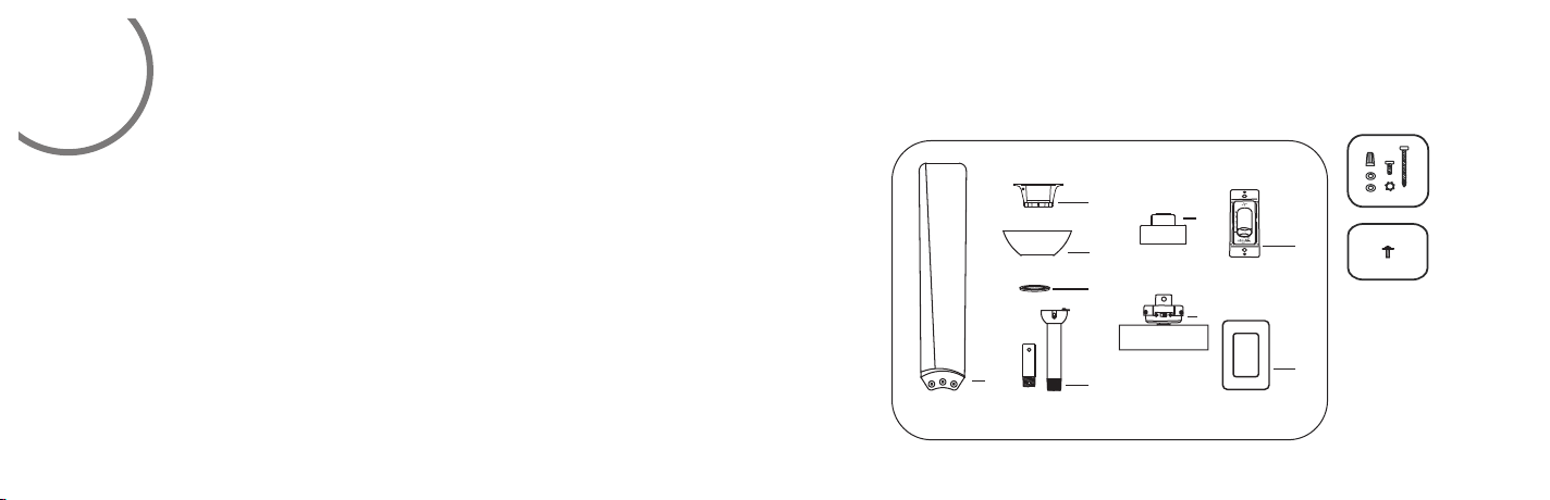
Unpack your fan and check the contents. You should have the following items:
1. Fan blades(3)
2. Hanger bracket
3. Canopy
4. Canopy cover
5. Standard downrod assembly(6")
Minimum-length downrod(3.5")
6. Coupling cover
7. Fan motor/housing assembly
8. Wall control with 2 mounting
screws and 3 wire nuts
9. Wall plate with 2 mounting screws
A. Mounting hardware:
Wire nuts(3)
#8x3/4”Machine screws (2)
#10x1.5Wood screws (2)
4mm Star washers (2)
Metal washers (2)
Lock washers (2)
B. Blade attachment hardware:
3/16“x12.7mm screws (10)
2
3
4
1
5
6
7
A
8
B
9
Page 9
INSTALLING THE FAN
Tools Required: Philips screw driver, slotted screw driver, step-ladder, wire cutters, electrical tape.
MOUNTING OPTIONS
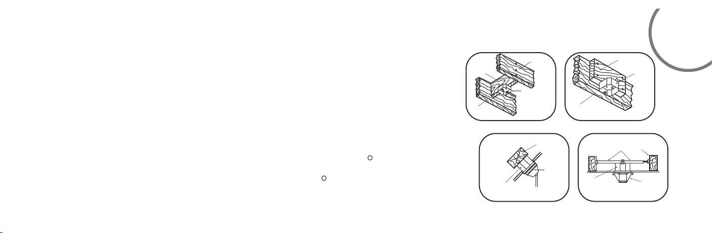
If there isn't an existing mounting box, then read the following instructions. Disconnect the
power by removing fuses or turning off circuit breakers.
Secure the outlet box directly to the building structure. Use appropriate fasteners and
building materials. The outlet box and its support must be able to fully support the moving
weight of the fan (at least 50 lbs.).Use a UL listed metal outlet box.
Do not use a plastic outlet box.
Figure1,2 and 3 are examples of different ways to mount the outlet box.
Note: You may need a longer downrod to maintain proper blade clearance when installing on
a steep, sloped ceiling. Longer downrods are available from your Minka-Aire dealer.
To hang your fan where there is an existing fixture but no ceiling joist, you may need to
install a hanger bar as shown in Fig.4(available at your Minka Aire dealer or local hardware store).
R
R
CROS S BRACE
CEIL ING
jOIS T
FIG. 1
ANGL ED CEIL ING
MAXI MUM 18° AN GLE
RECE SSED
OUTL ET BOX
FIG. 3
CEIL ING
JOIS T
OUTL ET BOX
PROV IDE
STRO NG
SUPP ORT
HANG ER
OPEN ING
must be
FACING
UPSI DE
CEIL ING JOIS T OR
CROS S BRACE
FIG. 2
OUTL ET BOX
FIG. 4
PARAL LEL WOOD BRACE
(MIN . 2’’ THICK )
OUTL ET
BOX
CEIL ING
HANG ER BAR
(OPT IONAL )
JOIS T
HANG ER
BRAC KET
3
Page 10
4
BLADE INSTALLATION
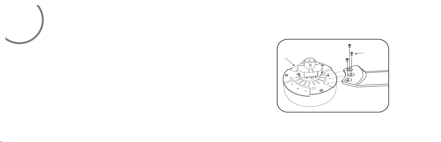
Align the 3 holes from the blade to the fan motor.
Secure blade with 3 blade screws provided. Follow the same process for the remaining
two blades. (Fig. 5)
All blade sets are grouped together by weight.
Fan m oto r
Scr ew
Blade
Fig. 5
Page 11

HANGING THE FAN
5
WARNING: All of the parts, hardware and components such as the
hanger bracket and hanger ball have been provided for your safety and
the proper installation of your new ceiling fan. The use of other
parts,hardware or components not supplied by Minka Aire with the fan
will void the Minka Aire Warranty.
REMEMBER to turn off the power. Follow the steps below to hang your
fan properly:
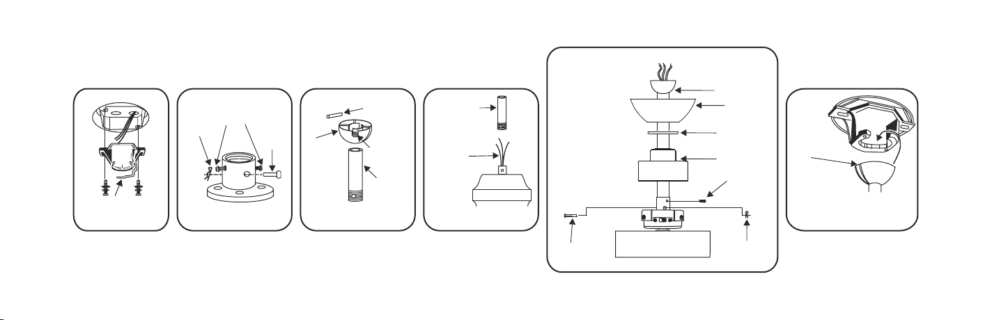
Step 1.Secure the hanger bracket to the ceiling outlet box using screws
and washers included with mounting hardware.(Fig.6)
Stpe 2.Lossen the two set screws and remove the hitch pin and lock pin
from the top coupling of the motor assembly.(Fig 7)
Step 3.Remove hanger ball from downrod assembly by loosening set
screw,removing the cross pin, and sliding ball off rod.(Fig 8)
R
R
Step 4.Carefully feed fan wires up through the downrod(Fig 9).
Thread the rod into the coupling, next line up holes and replace lock
pin and hitch pin. Tighten set screws.
Step5.Slip coupling cover, canopy cover, and canopy onto downrod
(Fig.10).Carefully reinstall hanger ball onto rod being sure that cross
pin is in the correct position, set screws are tighten and wires are
not twisted.
NOTE:DO NOT INSTALL THE COUPLING COVER IF YOU PLAN TO USE
THE MINIMUM LENGTH DOWNROD.
Step 6. Now lift motor assembly into position and place hanger ball
into hanger bracket. Rotate until the check groove has dropped into
the registration slot and seats firmly.(Fig 11)Rod should not rotate if
this is done correctly.
Page 12
OUT LET BOX
Fig. 10
LOCK PIN
COU PLING
COV ER
DOWNROD
CAN OPY
SCR EWS
HITCH PIN
CAN OPY
COV ER
HAN GER BR ACK ET
Fig. 6
HIT CH
PIN
Fig. 7
SET SCREW S
LOC K
PIN
HAN GER
BAL L
Fig. 8
CRO SS PIN
SET SCREW
DOW NROD
DOW NROD
SUP PLY
WIR ES
Fig. 9
REGISTRATION
SLOT
Fig. 11
Page 13
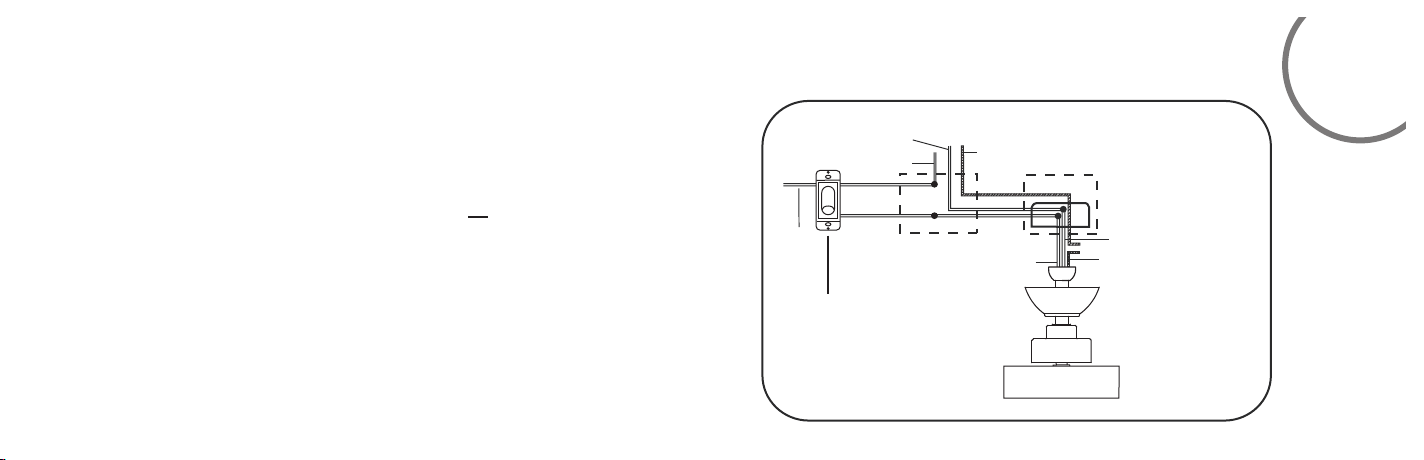
Follow the steps below to connect the fan to your house supply wires.
Use the wire nuts supplied with your fan. Secure the wire nuts by wrapping
the connection with electrical tape.
Step 1. Disconnect the power and remove the existing wall plate and switch
from the wall junction box.
Step 2. Set knobs on the wall control in the “ “ position.
Step 3. Make wire connections (Fig. 12) and secure with wire nuts supplied.
• Black wire from fan to black wire from wall control.
• Black wire from wall control to black wire from the A/C supply source.
• White wire from fan to white wire from the A/C supply source.
• Connect the fan ground wire (green) to the household ground wire.
If your outlet box has a ground wire (green or bare copper) connect the wall
control's ground wire to it; otherwise connect the wall control's ground
wire directly to one of the screws from the outlet box.
ELECTRICAL CONNECTIONS
WHITE (NEUTRAL)
GREEN
(GROUND)
FAN WALL CONTROL
Fig.12
BLACK (HOT)
BLACK
HOUSE WIRE SUPPLY
GREEN (GROUND)
CEILING
WALL
BLACK (MOTOR)
WHITE (NEUTRAL)
GROUND
(CONNECT TO GROUND WIRE ON
HANGER BRACKET IF NO HOUSE
GROUND WIRE EXISTS.)
6
Page 14
7
INSTALLING THE WALL CONTROL
Remember to shut the power off at the circuit breaker or fuse box.
WARNING: HOOK UP IN "SERIES ONLY" DO NOT CONNECT THE HOT AND
NEUTRAL WIRES OF ELECTRIC CIRCUIT TO THE WALL CONTROL - DAMAGE TO
THE SWITCH AND POSSIBLE FIRE COULD OCCUR.
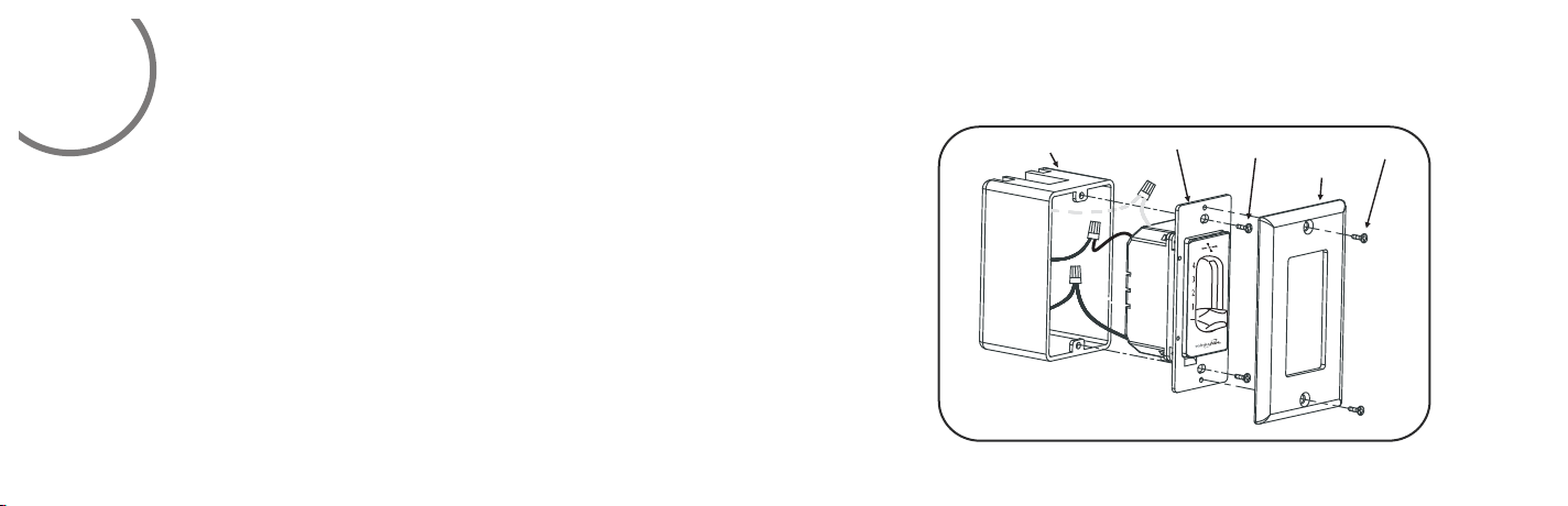
1. (Fig. 13) Carefully tuck the wire connections inside the outlet box. Secure the wall
control with the two screws provided.
2. Attach the wall plate over the wall control and secure with the two screws
provided.
Outlet box
Fig.13
Wall control
Screws
Wall plate
Screws
Page 15
FINISHING THE INSTALLATION
8
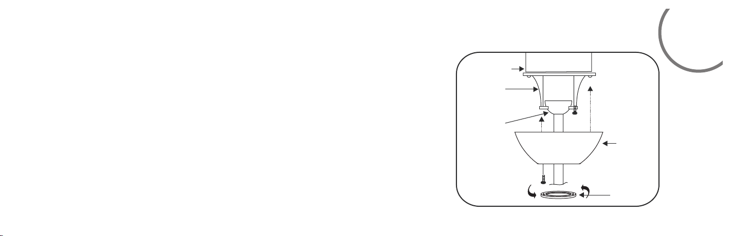
Step 1. Tuck connections neatly into ceiling outlet box.
Step 2. Remove one screw from the hanger bracket and loosen the other screw around
1/4”.
Step 3. Align the canopy up to ceiling and over the loose screw. Place the c anopy into
key hole and rotate canopy clockwise. (Figure 14)
Step 4. Secure the canopy by use previous removed screw.
Step 5. Place the canopy cover to the canopy and rotate canopy cover clockwise until
it is locked into right position. (Figure 14)
OUTLET BOX
HANGER
BRACKET
HANGER
BALL
Fig. 14
CANOPY
CANOPY
COVER
Page 16
9
Restore power to ceiling fan and test for proper operation.
The fan 4-speed control is used to set the fan speed as follows:
= Turns the fan off
1= High Speed
2= Medium High Speed
3= Medium Speed
4= Low Speed
Speed settings for warm or cool weather depend on factors such as the room size. Ceiling
height, number of fans, etc.
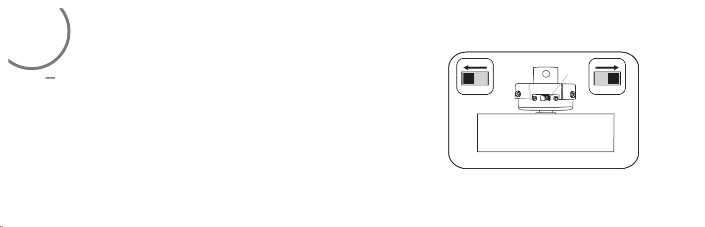
The Reverse switch is located on the coupling. (Fig 15) Slide the switch to the left for
warm weather operation. Slide the switch to the right for cool weather operation.
NOTE: Wait for fan to stop before changing the setting of the slide switch.
OPERATING YOUR FAN
War m
weathe r
Fig. 15
Revers e
switch
Cool
weathe r
Page 17
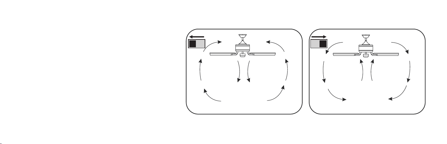
Warm Weather(forward)
A DOWNWARD airflow creates a cooling effect as shown
in Figure 16. This allows you to set your air conditioner on a
warmer setting without affecting your comfort.
Cool Weather(Reverse)
An UPWARD airflow moves warmer air off the ceiling
area as shown in Figure 17. This allows you to set your
heating unit on a cooler setting without affecting your
comfort.
SUMMER OPERATION
WINTER OPERATION
Fig. 16
Fig. 17
Page 18

10
CARE OF YOUR FAN
Here are some suggestions to help maintain your fan.
1.Because of the fan’s natural movement some connections may
become loose. Check the support connections, brackets and blade
attachment twice a year. Make sure they are secure.(It is not necessary
to remove fan from the ceiling).
2.Clean your fan periodically to help maintain its new appearance over
the years. Use only a soft brush or lint free cloth to avoid scratching
the finish. Plated finishes are sealed with lacquer to minimize
discoloration or tarnishing.
Do not use water when cleaning, this could damage the motor, wood
blades or possibly cause an electrical shock.
3.Use a lint free lightly damp cloth or duster to remove dust from the
blades.
4.There is no need to oil your fan. The motor has permanently
lubricated bearings.
5.If your fan is provided with glass shades, clean with lukewarm
soapy water and a soft cloth or sponge. DO NOT IMMERSE
GLASS SHADES IN HOT WATER. DO NOT PUT GLASS SHADES
INTO AN AUTOMATIC DISHWASHER.
WAR NING
MAK E S URE THE PO WER IS OFF AT TH E E LECT RICA L P ANEL
BOX BE FORE YO U A TTEM PT ANY REP AIR S. R EFE R T O TH E
SEC TION ”EL ECTR ICAL CO NNEC TIO NS”.
Page 19
SYMPTOM
Fan will not start
SOLUTION
Check to make sure the wall switch is turned on.
Check circult fuses or breakers.
Caution! Make sure the power is turned off before performing the
following steps.
Remove canopy and check wire connections.
Check wall control transmitter connections(if applicable).
Note:fan must be installed at a maximum distance of 40 feet from
the transmitting unit for proper signal transmission between the
transmitting unit and the fan’s receiving unit.
TROUBLESHOOTING
SYMPTOM
Fan Sounds Noisy
SOLUTION
Allow a 24 - hour “ break in ” period. Most noises associated
with a new fan will go away during this time.
Make sure the screws that attach the fan blade holder to the
motor hub is tight.
Make sure outlet box is secured to building structure, if
necessary use the wood screws provided to fruther secure
outlet box to joist.
Make sure hanger bracket is secure to the outlet box,screws are
tight.
11
Page 20

SYMPTOM
Fan Wobble
SOLUTION
NOTE: All bl ade sets are g rouped by we ight.
Make sure ou tlet box is se cured to bui lding structure, if necessary use the wood screws provided to further secure outlet box to joist.
Make sure ha nger brack et is secure t o the outlet box, screws are tight.
If a Balanci ng kit is prov ided follo w the instructions included with the balancing kit to help correct any excessive wobble.
Page 21
These are typical readings. Your actual fan may vary.
They do not include amps and wattage used by
the light (s).
For any additional information about your
Minka Aire Ceiling fan, please write to:
R
R
52”
High
Med. High
Medium
Low
120
120
120
120
0.44
0.34
0.26
0.17
SPECIFICATIONS
51.3
29.9
18.3
7.5
212
161
127
74
5816
4473
3519
2060
4.70
5.80
12
1.397’
Page 22
Low
Medium
Med. High
High
2060
3519
4473
5816
7.5
18.3
29.9
51.3
275
192
150
113
 Loading...