

Minipack-torre S.p.A.
Via Provinciale, 54 - 24044 Dalmine (BG) - Italy
Tel. (035) 563525 – Fax (035) 564945
E-mail: info@minipack-torre.it
http://www.minipack-torre.it
IT ISTRUZIONI PER L’INSTALLAZIONE, L’USO E LA MANUTENZIONE
EN INSTALLATION, OPERATION AND MAINTENANCE
DE INSTALLATIONS-, GEBRAUCHS- UND WARTUNGSANLEITUNG
FR INSTRUCTIONS POUR L’INSTALLATION, L’EMPLOI ET L’ENTRETIEN
ES INSTRUCCIONES PARA LA INSTALACIÓN, USO Y MANTENIMENTO
PT INSTRUÇÕES PARA A INSTALAÇÃO, O USO E A MANUTENÇÃO
EL Ο∆ΗΓΙΕΣ ΓΙΑ ΤΗΝ ΕΓΚΑΤΑΣΤΑΣΗ, ΤΗ ΧΡΗΣΗ ΚΑΙ ΤΗ ΣΥΝΤΗΡΗΣΗ
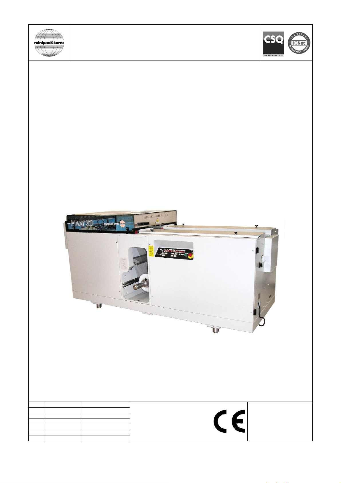
mod. Plexi 30
mod. Plexi 60
IT LEGGERE ATTENTAMENTE QUESTE ISTRUZIONI PRIMA DI USARE LA MACCHINA
EN BEFORE USING THE MACHINE PLEASE CAREFULLY READ THE INSTRUCTIONS
DE BITTE LESEN SIE DIESE ANLEITUNG GENAU DURCH, BEVOR SIE DIE MASCHINE BENÜTZEN
FR PRIERE DE LIRE ATTENTIVEMENT CE MANUEL D’INSTRUCTIONS AVANT D’UTILISER LA MACHINE
ES LEER ATENTAMENTE ESTE MANUAL ANTES DE USAR LA MÁQUINA
PT ANTES DE USAR A MÁQUINA LER CUIDADOSAMENTE ESTE MANUAL
EL ∆ΙΑΒΑΣΤΕ ΜΕ ΠΡΟΣΟΧΗ ΤΙΣ ΠΑΡΑΚΑΤΩ Ο∆ΗΓΙΕΣ ΧΡΗΣΕΩΣ ΠΡΙΝ ΧΡΗΣΙΜΟΠΟΙΗΣΕΤΕ ΤΗ ΣΥΣΚΕΥΗ
Italiano Pagina 02
IT
English Page 13
EN
Deutsch Seite 24
DE
Français Page 35
FR
Español Pagina 46
ES
Português Página 57
PT
Ελληνικά Σελίδα 68
EL
DOC. N. FM111522
REV. 01
ED. 11.2011

ISTRUZIONI ORIGINALI
Indice IT
Capitolo 1. Descrizione
1.1. Prefazione pagina 03
1.2. Dati tecnici della macchina pagina 03
1.3. Descrizione della macchina pagina 04
Capitolo 2. Installazione della macchina
2.1. Trasporto e posizionamento pagina 04
2.2. Condizioni ambientali pagina 04
2.3. Collegamento elettrico pagina 05
2.4. Collegamento pneumatico pagina 05
Capitolo 3. Regolazione ed approntamento macchina
3.1. Pannello comandi pagina 05
3.2. Inserimento bobina film pagina 06
3.3. Confezionamento pagina 07
3.4. Regolazione lunghezza busta e rear pagina 07
3.5. Inconvenienti e possibili rimedi pagina 08
Capitolo 4. Caratteristiche del film
4.1. Films da adoperare pagina 09
Capitolo 5 Norme di sicurezza
5.1. Precauzioni generali pagina 09
5.2. Precauzioni specifiche pagina 09
Capitolo 6. Manutenzione ordinaria
6.1. Cautele per interventi di manutenzione ordinaria pagina 10
6.2. Verifica usura e livelli pagina 10
6.3. Pulizia della macchina pagina 10
6.4. Sostituzione del colletto pagina 11
6.5. Sostituzione del cavo di alimentazione pagina 11
6.6. Schema elettrico pagina 11
6.7. Schema pneumatico pagina 12
6.8. Smontaggio, demolizione e smaltimento residui pagina 12
Capitolo 7. Garanzia
7.1. Certificato di garanzia pagina 12
7.2. Condizioni di garanzia pagina 12
Dichiarazione CE di conformità pagina 79
2
Capitolo 1. Descrizione IT
1.1. Prefazione
Il presente manuale è redatto nel rispetto della norma UNI 10893 del Luglio 2000. È rivolto a tutti gli utilizzatori al fine di
consentire un corretto uso della macchina. Conservarlo in luogo facilmente accessibile vicino alla macchina e noto a tutti
gli utilizzatori. Il presente manuale è parte integrante della macchina ai fini della sicurezza. Per migliorare la
comprensione precisiamo di seguito i simboli utilizzati.
Tutti i diritti di riproduzione del presente manuale sono riservati alla ditta costruttrice. La riproduzione, anche parziale, è
vietata a termini di legge. Le descrizioni e le illustrazioni presenti in questo manuale non sono impegnative, di
conseguenza la ditta costruttrice si riserva il diritto di apportare in qualsiasi momento tutte le modifiche che riterrà
opportune. Il presente manuale non può essere ceduto in visione a terzi senza autorizzazione scritta della ditta
costruttrice. La macchina deve essere utilizzata solo per soddisfare le esigenze per cui è stata concepita, ogni altro uso è
da considerarsi “uso improprio”, quindi pericoloso.
Prima di compiere qualsiasi operazione sulla macchina è obbligatorio leggere attentamente tutte le istruzioni del presente
manuale, al fine di evitare possibili danneggiamenti alla macchina stessa, alle persone ed alle cose.
Non è consentito operare in caso di dubbi sulla corretta interpretazione delle istruzioni.
Interpellare il fabbricante per ottenere i necessari chiarimenti.
La macchina non è destinata a essere usata da persone (bambini compresi) le cui capacità fisiche, sensoriali o mentali
siano ridotte, oppure con mancanza di esperienza o di conoscenza, a meno che esse abbiano potuto beneficiare,
attraverso l’intermediazione di una persona responsabile della loro sicurezza, di una sorveglianza o di istruzioni
riguardanti l’uso dell’apparecchio.
I bambini devono essere sorvegliati per sincerarsi che non giochino con la macchina.
Al momento della consegna verificare che la macchina sia completa in tutte le sue parti.
Eventuali anomalie dovranno essere presentate immediatamente al fornitore.
La ditta costruttrice declina ogni responsabilità per uso improprio della macchina e/o per danni causati in seguito ad
operazioni non contemplate in questo manuale.
1.2. Dati tecnici della macchina
Peso e dimensioni dell’imballo
Larghezza = 2940mm / Lunghezza = 1500mm / Altezza = 1440mm
Peso = 605Kg
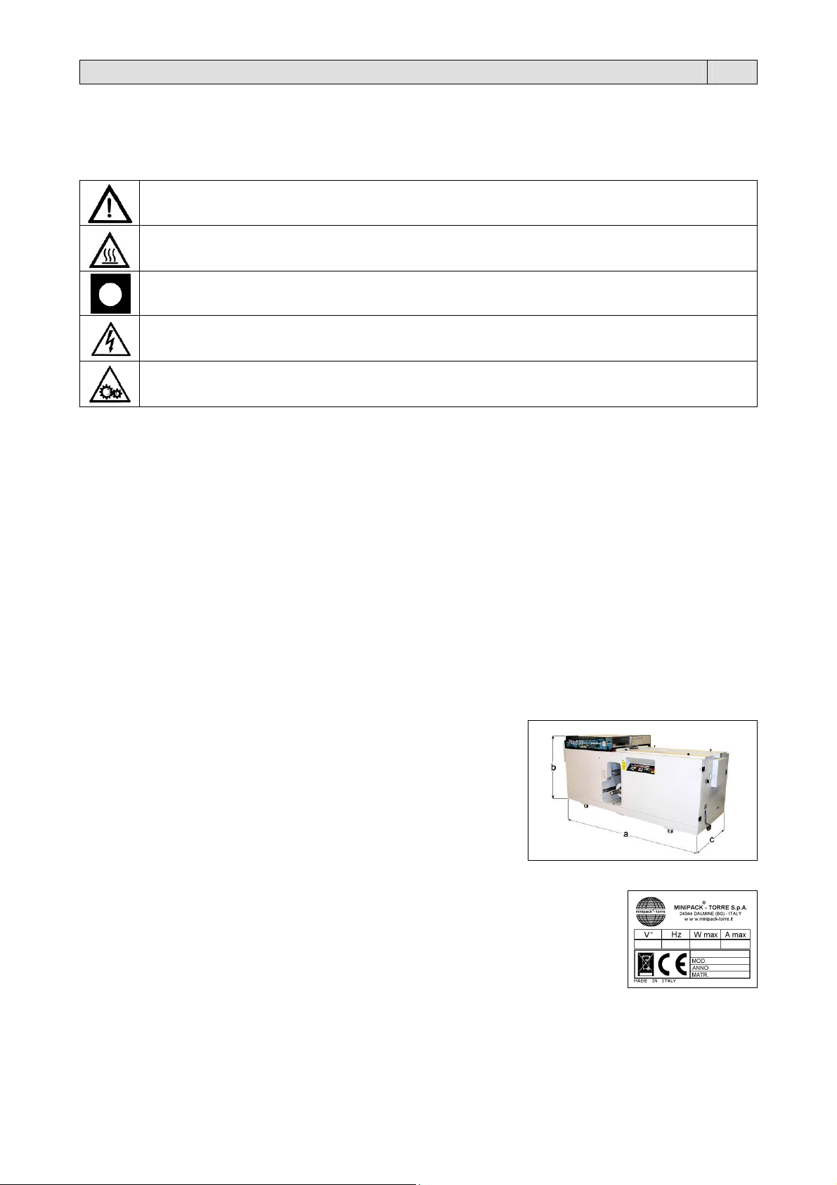
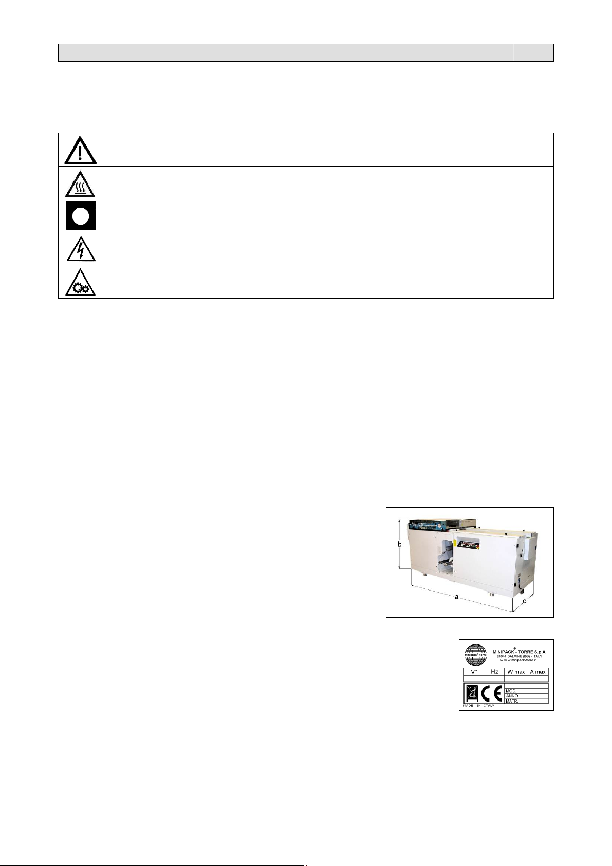
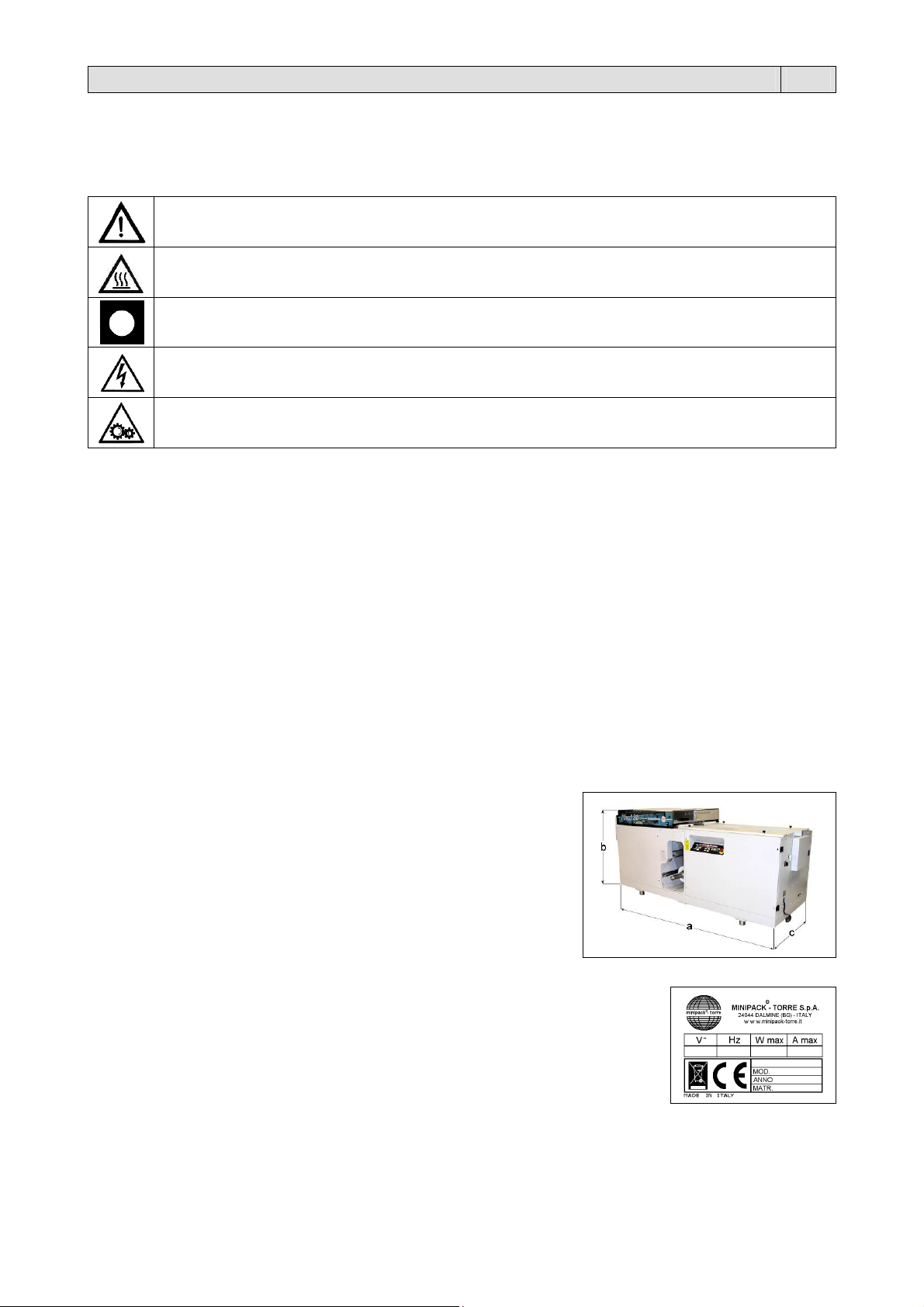
Peso e dimensioni della macchina
a = 2600mm
b = 960mm
c = 1160mm
Peso = 555Kg
Impianto elettrico
Tensione (V): vedere dati targhetta
Frequenza (Hz): vedere dati targhetta
Potenza massima assorbita (W): vedere dati targhetta
Corrente massima assorbita (A): vedere dati targhetta
N.B.: Per qualsiasi comunicazione con il costruttore, citare sempre il modello della macchina e il
numero di matricola indicati sulla targhetta applicata nella parte posteriore della macchina.
Consumo aria: 40 litri/min. a 4 bar.
Produzione massima: Plexi 30: 30 pezzi/min., formato A4 con film polietilene da 25 micron.
Dimensioni materiale da imbustare:
minimo A6
massimo A3 con spessore massimo 12mm
ATTENZIONE:
Norme antinfortunistiche per l’operatore. Tale avvertimento indica la presenza di pericoli che
possono causare lesioni a chi sta operando sulla macchina.
ATTENZIONE:
Organi caldi. Indica il pericolo di ustioni con rischio di infortunio, anche grave per la persona
esposta.
AVVERTENZA:
Indica la possibilità di arrecare danno alla macchina e/o ai suoi componenti.
ATTENZIONE:
Apparati sotto tensione: indica un pericolo di natura elettrica con rischio di infortunio, anche grave
per la persona esposta.
ATTENZIONE:
Organi in movimento: indica il pericolo di venire a contatto con organi in movimento con rischio di
infortunio, anche grave per la persona esposta.
Plexi 60: 60 pezzi/min., formato A4 con film polietilene da 25 micron.
3
Capitolo 1. Descrizione IT
1.3. Descrizione della macchina
La “Plexi” è una imbustatrice orizzontale automatica. Può essere utilizzata inserendo le riviste manualmente oppure
utilizzando appositi caricatori opportunamente sincronizzati.
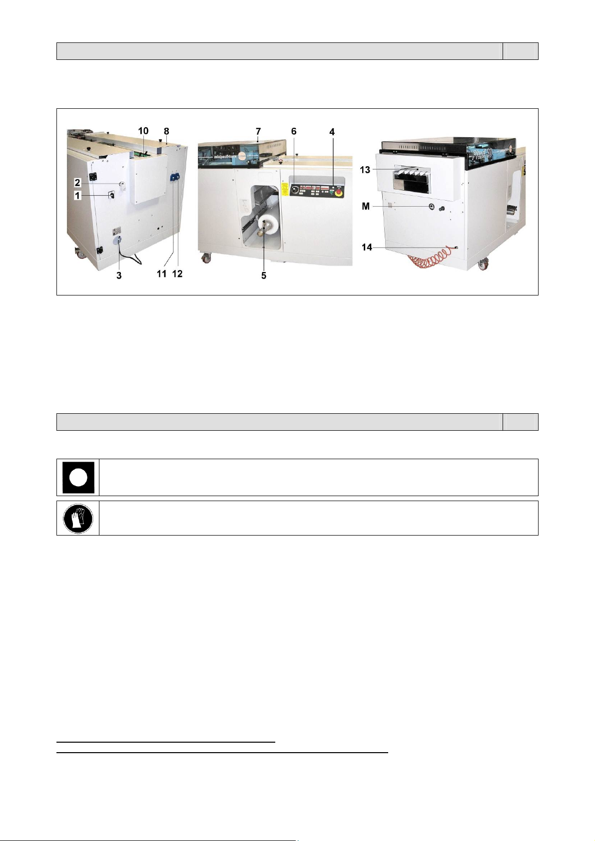
1 Interruttore generale
2 Presa per interfacciamento con dispositivi a monte
3 Cavo alimentazione elettrica
4 Quadro comandi
5 Zona bobina film
6 Potenziometro per la variazione della lunghezza della
busta
7 Coperchio zona saldatura trasversale
8 Piedini di appoggio guide laterali regolabili e relativi
pomelli di blocco
10 Zona carico riviste
11 Presa ausiliaria
12 Presa ausiliaria comandata per optional (saldatore
elettrostatico)
13 Zona scarico pacchi inbustati
14 Attacco aria compressa
M Manometro.
Capitolo 2. Installazione della macchina IT
2.1. Trasporto e posizionamento
Nel trasporto e nel posizionamento della macchina si raccomanda di manovrare con molta cautela!
Procedere al sollevamento mediante carrello elevatore di portata adeguata (prestare attenzione al bilanciamento della
macchina e alle viti sporgenti nella parte inferiore della scocca) o in alternativa mediante imbragatura e mezzo di
sollevamento idoneo tramite funi correttamente dimensionate e provviste di ganci alle estremità.
La macchina viene fornita con i piedi fissi; non usare la macchina se posizionata su ruote (gli spostamenti potrebbero
alterarne il buon funzionamento).
2.2. Condizioni ambientali
Posizionare la macchina accertandosi che sia livellata sul pavimento, in un ambiente adatto, privo di umidità,
Lasciare uno spazio minimo di 0,5m attorno alla macchina, per non ostruire le prese d’aria.
Condizioni consentite negli ambienti in cui é collocata la macchina:
Temperatura da + 5°C a + 40°C
Umidità relativa da 30% a 90% senza condensazione.
L’illuminazione del locale di utilizzo deve essere conforme alle leggi vigenti nel paese in cui è installata la macchina e
deve comunque essere uniforme e garantire una buona visibilità, per salvaguardare la sicurezza e la salute
dell’operatore.
GRADO DI PROTEZIONE DELLA MACCHINA = IP20
IL RUMORE AEREO PRODOTTO DALLA MACCHINA È INFERIORE A 70 dB(A)
Nella movimentazione della macchina utilizzare guanti di protezione.
materiali infiammabili, gas, esplosivi. La macchina deve essere installata solamente su superfici lisci, orizzontali e
non infiammabili.
4
5
Capitolo 2. Installazione della macchina IT
2.3. Collegamenti elettrico
RISPETTARE LE NORME PER LA SICUREZZA SUL LAVORO!
Se la macchina non è dotata della spina di alimentazione utilizzare una spina adeguata ai
valori di tensione e amperaggio descritti nella targhetta dati e comunque conforme alle
normative vigenti nel paese d’installazione.
È OBBLIGATORIA LA MESSA A TERRA!
Prima di effettuare il collegamento elettrico assicuratevi che la tensione di rete corrisponda
al voltaggio indicato sulla targhetta applicata nella parte posteriore della macchina e che il
contatto di terra sia conforme alle norme di sicurezza vigenti. In caso di dubbi sulla tensione
di rete contattate l’ente locale distributore dell’energia elettrica.
Collegare la spina del cavo proveniente dal quadro elettrico della macchina in una presa di
corrente del circuito generale che sia facilmente raggiungibile dall’operatore.
2.4. Collegamento pneumatico
Collegare, con una tubazione avente diametro minimo di passaggio di 6mm e con raccordo da 1/4” femmina, l’attacco
dell’aria compressa 14 (figura 1.3 pag.4) posto sul lato uscita della macchina.
Capitolo 3. Regolazione ed approntamento macchina IT
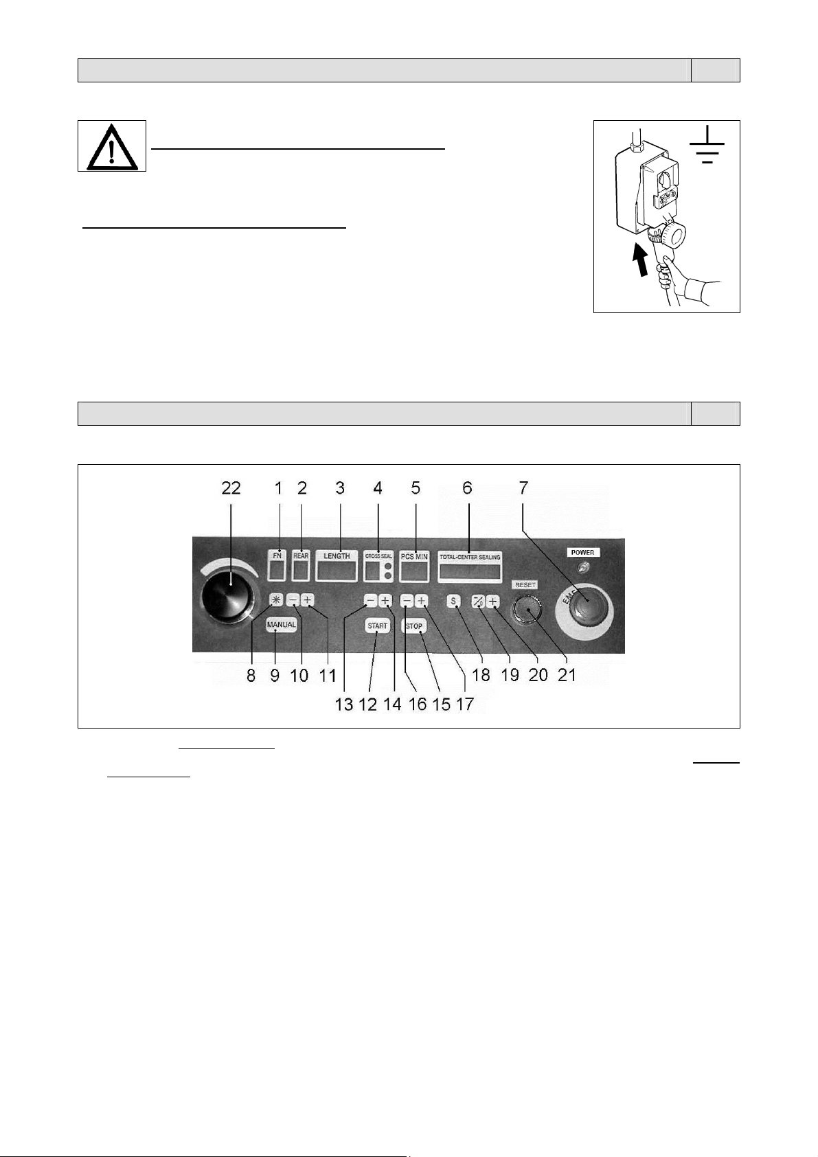
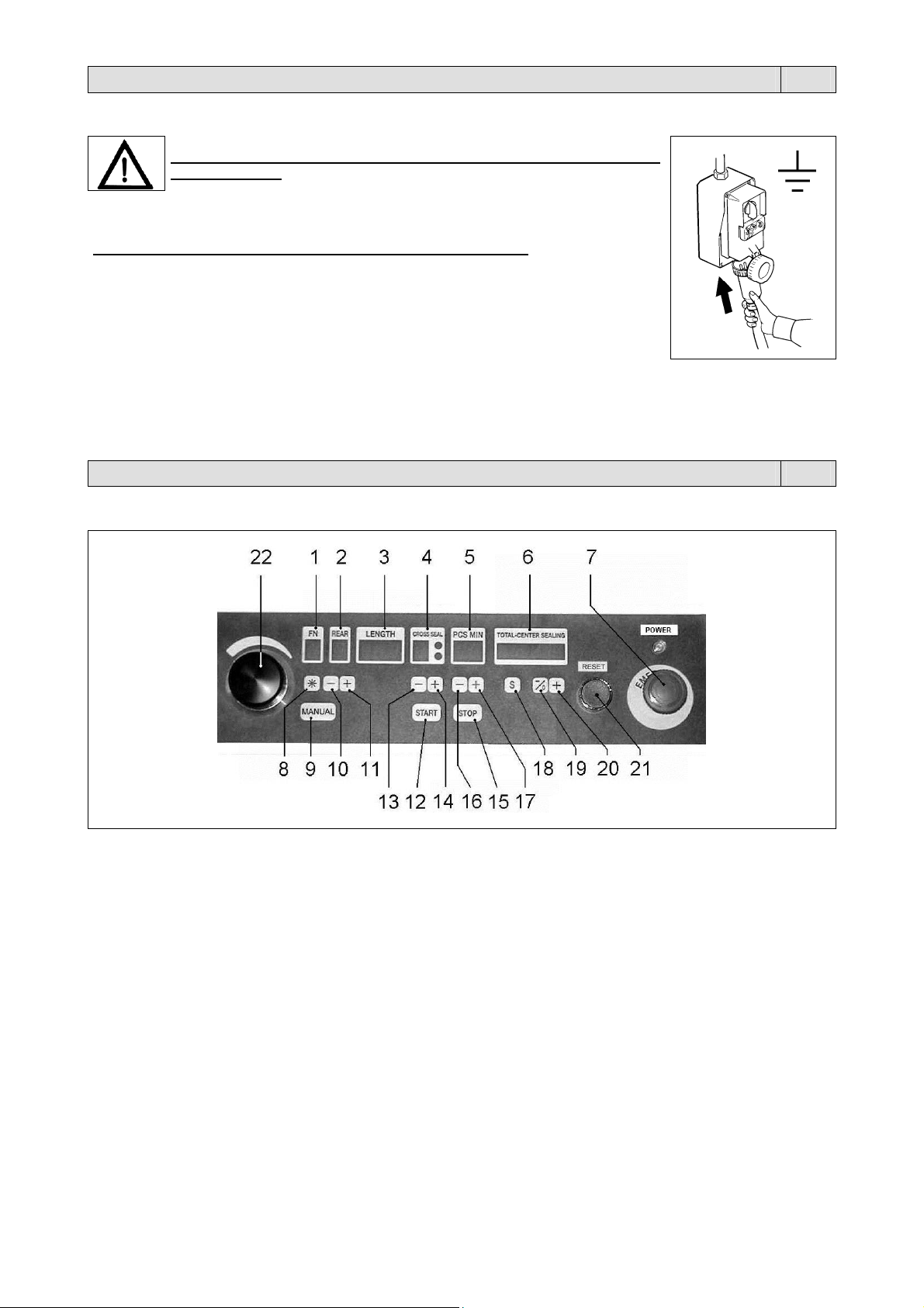
3.1. Pannello comandi
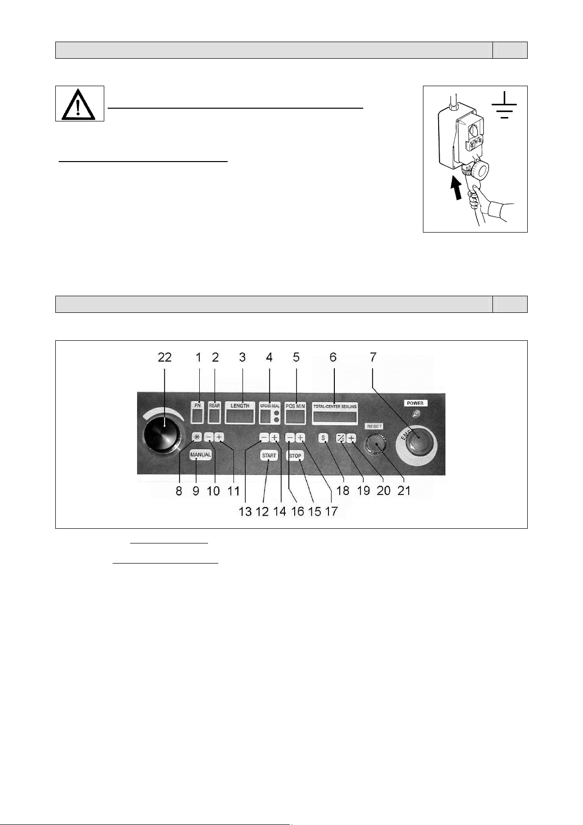
1. Display FN. Visualizza “J” (Jog) se sono state eseguite operazioni manuali o di manutenzioni sulla macchina,
oppure non è ancora stata eseguita la manovra di reset. Per eseguire la manovra di reset premere il pulsante
START. Visualizza “A” (Automatico) se la macchina è pronta per lavorare.
2. Display REAR. Visualizza la quantità di film dietro il prodotto.
3. Display LENGTH. Visualizza la lunghezza della busta.
4. Display CROSS SEAL. Visualizza la temperatura della saldatura trasversale (pinze).
5. Display PCS MIN. Visualizza la quantità di buste prodotte per minuto.
6. Display TOTAL-CENTER SEALING. Visualizza la quantità di buste prodotte. Per resettare tenere premuto il pulsante
(19).
7. Pulsante di emergenza. Arresta immediatamente la macchina in caso di pericolo immediato o per la “messa in
stato di manutenzione”. Per sbloccarlo occorre girarlo in senso orario.
8. Pulsante di RESET. Per allarmi E5, E6, E7, E12, E13.
9. Pulsante di azionamento spintori. A macchina ferma, se premuto contemporaneamente con il pulsante START,
fa avanzare gli spintori.
10. Pulsante pinza A. Se premuto contemporaneamente con il pulsante 9 apre e chiude la pinza A.
11. Pulsante pinza B. Se premuto contemporaneamente con il pulsante 9 apre e chiude la pinza B.
12. Pulsante START. Avvia il ciclo di confezionamento.
Premere una prima volta per portare la macchina in posizione START.
Premere una seconda volta per iniziare il ciclo di confezionamento.
13. Pulsante “DECREMENTA”. Riduce il tempo dell’impulso di saldatura delle pinze (vedere nota Nr.1).
14. Pulsante “INCREMENTA”. Aumenta il tempo dell’impulso di saldatura delle pinze (vedere nota Nr.1).
15. Pulsante STOP. Arresta il ciclo di confezionamento.

Capitolo 3. Regolazione ed approntamento macchina IT
16. Pulsante “DECREMENTA”. Riduce il numero di pezzi da produrre al minuto (vedere nota Nr.2).
17. Pulsante “INCREMENTA”. Aumenta numero di pezzi da produrre al minuto (vedere nota Nr.2).
18. Pulsante temperatura saldatura centrale. Premendo questo pulsante il display TOTAL-CENTER SEALING
visualizza la temperatura della saldatura centrale. I valori sono indicativi e non espressi in gradi.
19. Pulsante “DECREMENTA”. Riduce la temperatura della saldatura centrale.
Inoltre premendo questo pulsante si resetta il contapezzi (display TOTAL-CENTER SEALING).
20. Pulsante “INCREMENTA”. Aumenta la temperatura della saldatura centrale.
21. Pulsante RESET. Da premere all’accensione della macchina.
Ripristina la macchina dopo l’intervento del pulsante di emergenza.
22. Potenziometro. Consente la regolazione della lunghezza delle buste.
Nota Nr.1: utilizzare il “tempo di saldatura” minimo necessario ad ottenere la saldatura della busta. Utilizzare tempi
elevati non migliora il risultato, ma deteriora precocemente il nastro in gomma.
Nota Nr.2: la quantità di pezzi al minuto dipende da: esperienza dell’operatore, dimensioni della rivista, numero di riviste
da inserire, tipo di film utilizzato.
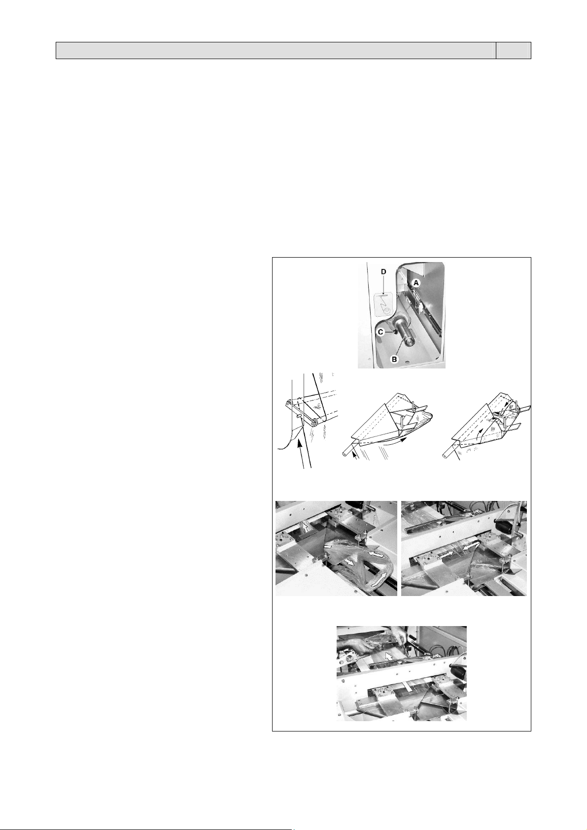
3.2. Inserimento bobina film
Rimuovere la vite di fissaggio A.
Estrarre lo svolgitore B e inserire la bobina sull’asse
dello svolgitore bloccandola mediante il cono
centratore C.
Fare passare il film attorno al ballerino di comando
dello svolgitore (figura 1), come indicato anche sulla
targhetta adesiva D.
Portare manualmente il film nella parte superiore
della macchina (figura 2).
Avvolgere in modo adeguato il colletto (figura 3).
Far passare il film attraverso i colletti fino a portarlo
sopra il tappeto folle (figura 4).
Stendere accuratamente il film come indicato (figura
5).
Tirare manualmente il film e controllare la posizione
dei due lembi inferiore e superiore fino a formare il
tubo.
1
4
2
5
3
6
Capitolo 3. Regolazione ed approntamento macchina IT
3.3. Confezionamento
Ruotare l’interruttore generale 1 nella posizione 1.
Premere il pulsante RESET. Premere il pulsante START per iniziare il ciclo di confezionamento.
Posizionare manualmente le riviste davanti agli spintori con le guide laterali opportunamente regolate.
Gli spintori introducono le riviste all’interno del conformatore del film (colletto) mentre un dispositivo effettua la saldatura
longitudinale.
Le buste avanzano appoggiate su un tappeto folle, trascinato da due pinze che, tramite un movimento alternato,
eseguono anche la saldatura e il taglio tra le buste espellendole poi attraverso l’apertura di uscita della macchina.
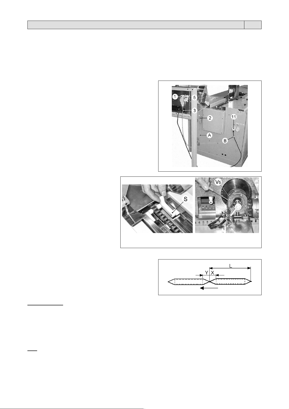
L’inserimento delle riviste oltre ad essere manuale, si può
effettuare utilizzando appositi caricatori opportunamente
sincronizzati (optional).
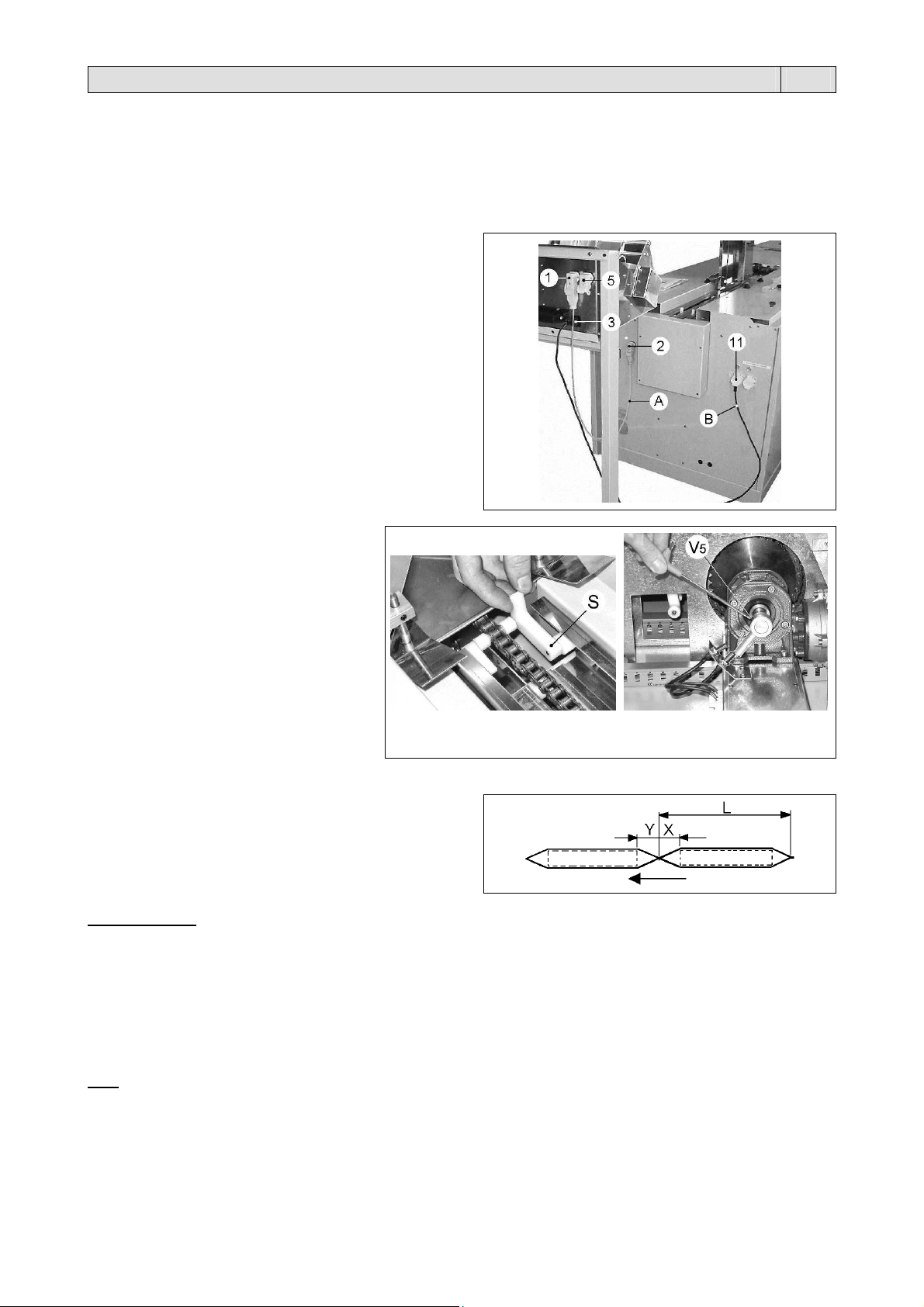
Il collegamento del caricatore alla macchina si effettua nel
seguente modo.
collegare il cavo A (di interfacciamento) alla presa 1 (sul
caricatore), ed alla presa 2 (sulla macchina)
collegare il cavo B (di tensione) alla presa 3 (sul caricatore),
ed alla presa 11 (sulla macchina).
La presa 5 (sul caricatore) serve in caso occorra più di un
caricatore per alimentare la macchina; essa permette di collegare
in serie fra loro 2 o più caricatori.
N.B.: se a monte della macchina è
installata una prolunga è necessario
mettere in fase gli spintori della macchina
con quelli della stessa prolunga.
Per regolare la posizione esatta in cui far
partire gli spintori, agire come segue:
tenere premuto il pulsante 9 “MANUAL” e
con il tasto 12 “START” dare dei brevi
impulsi sino a portare uno spintore S
qualsiasi in posizione di caduta (figura 1)
posizionare il tastatore dei micro come
nella foto, agendo sulla vite V5 (figura 2).
1
2
3.4. Regolazione lunghezza busta e rear
“ L ” lunghezza della busta
“ X ” spazio direttamente collegato a “ L ”
“ Y ” rear.
La freccia indica la direzione in cui si muove il prodotto.
Lunghezza busta
La regolazione della lunghezza della busta si può effettuare solo con macchina in movimento.
Prima di effettuare la regolazione è utile escludere il microinterruttore (film lento) premendo contemporaneamente i
pulsanti 8 e 9 (un led luminoso sul display 1 - FN ne indica l’esclusione).
La lunghezza della busta “ L ”, da 120 a 420 mm, si regola ruotando il potenziometro 22.
Ruotando in senso antiorario la busta si allunga, ruotando in senso orario la busta si accorcia.
Automaticamente sul display 3 “LENGTH” compare la misura effettiva in millimetri. Stabilita la misura desiderata, dopo
aver riabilitato il microinterruttore (film lento) del ballerino, la macchina è pronta per il confezionamento.
Rear
Per regolare la lunghezza “ Y ”, modificare il valore visualizzato sul display REAR utilizzando i tasti 10 e 11.
È possibile impostare un valore da 1 a 9 (ogni numero corrisponde circa a 2,2mm).
Aumentando il valore aumenta la lunghezza della coda “ Y ” e viceversa.
Impostare “rear” in modo che la saldatura/taglio della busta sia a metà tra le due riviste.
7
Capitolo 3. Regolazione ed approntamento macchina IT
3.5. Inconvenienti e possibili rimedi
“ E ” lampeggiante sul display PCS - MIN = il passo della macchina non è più sincronizzato
La scheda elettronica invia regolarmente il comando di partenza alle pinze, ma queste non fanno in tempo a ritornare sulla loro
posizione di zero.
La macchina produce ancora, ma non è più in grado di garantire la misura esatta delle buste.
Diminuire “ PCS - MIN ”.
Controllare lo scorrimento dei carrelli delle pinze.
Controllare la pressione del manometro M (figura 1.3 pag.4) da 4 a 5,5bar.
E0 = Blocco saldatura
Spegnere la macchina.
Controllare eventuali cortocircuiti sulle linee di alimentazione delle barre saldanti.
Controllare il trasformatore T1 e T2.
Controllare il filo di saldatura delle pinze A e B.
Controllare la molla di compensazione del filo caldo delle pinze A e B.
Controllare la scheda (chiamare l’assistenza tecnica).
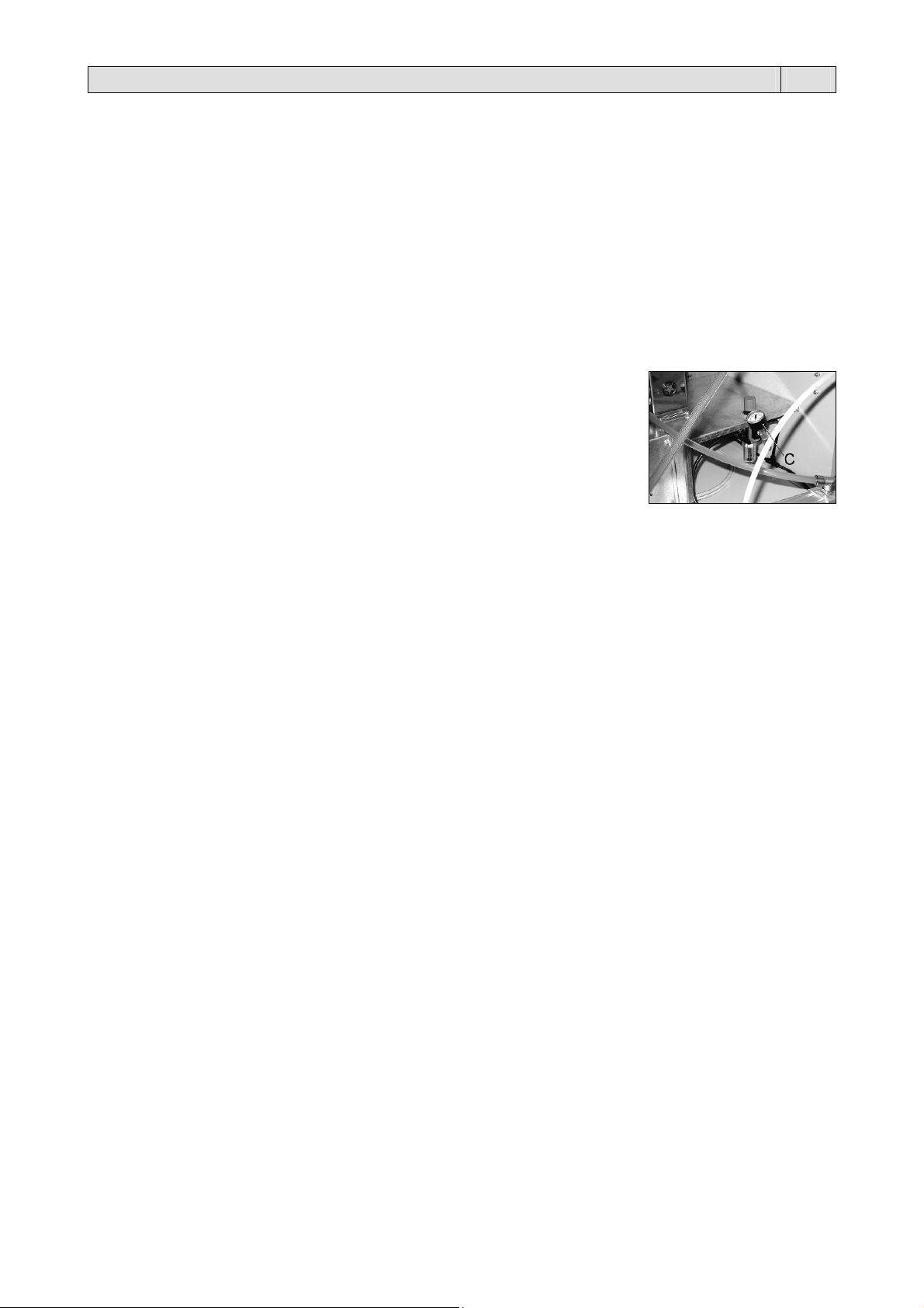
E01 = Allarme su pinza A (il movimento di apertura o chiusura della pinza A è durato più di 2 secondi).
E02 = Allarme su pinza B (il movimento di apertura o chiusura della pinza B è durato più di 2 secondi).
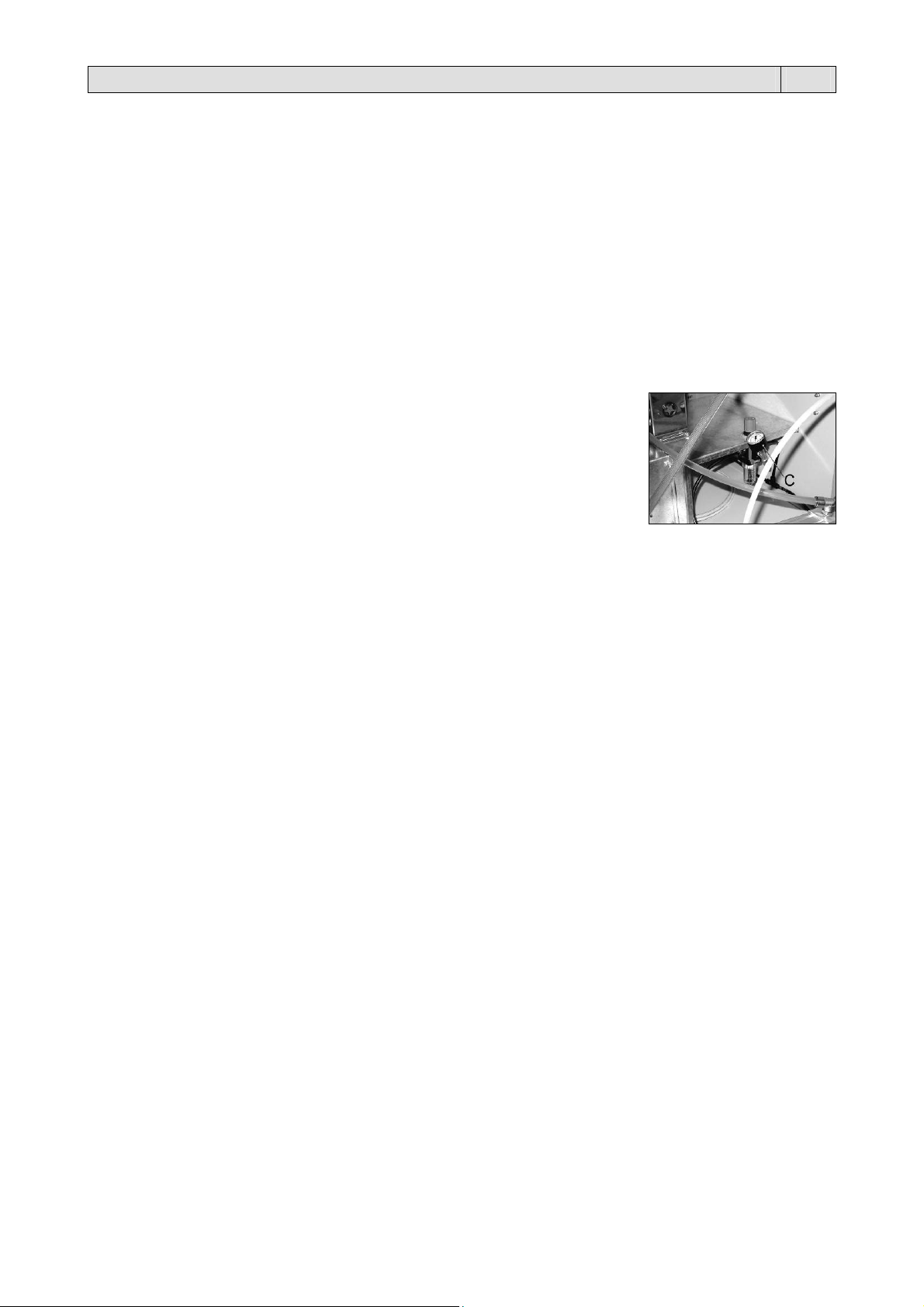
Spegnere la macchina e controllare l’aria compressa.
Il manometro C deve segnare 2,2 bar.
Quache organo meccanico della pinza si è bloccato.
Una rivista di grosso spessore è rimasta bloccata nella pinza.
Uno dei 2 sensori magnetici si è rotto.
Il magnete inserito nella spalla della pinza non si trova nella posizione corretta o non riesce ad
eccitare il sensore.
Chiamare l’assistenza tecnica.
E03 = Entrambe le pinze sulla propria posizione di 0
Spegnere la macchina.
Spostare manualmente in avanti una delle 2 pinze.
Riaccendere la macchina.
Chiamare l’assistenza tecnica.
E04 = Emergenza, una delle 2 pinze ha raggiunto il microinterruttore di finecorsa
Rimuovere la pinza dal finecorsa. Spegnere e riaccendere la macchina.
Diminuire “ pezzi / min. ” o “lung. Busta ”.
Controllare il funzionamento del finecorsa.
E05 = Microinterruttore del ballerino
Il film si è allentato troppo intorno al ballerino.
È finita la bobina del film. Sostituirla.
E06 = Microinterruttore sicurezza portellone
Premere (N°8).
Chiudere il portello superiore.
Controllare il microinterruttore del portello.
E07 = Sono stati memorizzati dati sbagliati, montaggio Eprom aggiornata
Premere (N°8).
Controllare la scheda.
E08 = Mancanza di tensione improvvisa
Controllare la tensione di rete.
E09 = Tempo massimo superato tra il passaggio di uno spintore e l’altro
Si ipotizza guasto ai meccanismi di traino degli spintori.
Spegnere la macchina, controllare il magnete sul riduttore di comando dell’alimentatore.
E10 = Corto circuito su 24V cc output
Spegnere la macchina.
Controllare il funzionamento delle elettrovalvole degli innesti elettromagnetici e delle altre utenze a 24V.
Chiamare l’assistenza tecnica.
E11 = Anomalia inverter
Controllare il motore e la catena dell’alimentatore delle riviste.
Controlare l’inverter, eventualmente sostituirlo.
Spegnere e riaccendere la macchina.
E12 = Film troppo teso
È finita la bobina. Sostituirla.
Guasto al motore dello svolgitore. Premere (N°8).
E13 = Dispositivo automatico di inserimento riviste vuoto
Premere (N°8).
Controllare il caricatore.
8
Capitolo 4. Caratteristiche del film IT
4.1. Films da adoperare
La macchina può lavorare con tutti i films termoretraibili e non (polietilene e polipropilene), con spessore da 15 a 30
micron sia di tipo tecnico che alimentare. Per garantire i migliori risultati è consigliato l’utilizzo dei films da noi
commercializzati.
Le speciali caratteristiche dei nostri films (anche con disegni e scritte personalizzate del cliente) danno garanzie di
affidabilità sia dal lato della corrispondenza alle normative di legge vigenti, che dal lato sicurezza di ottimo funzionamento
delle nostre macchine.
Si raccomanda di consultare le schede tecniche e di sicurezza dei films utilizzati e di attenersi alle
prescrizioni descritte!
Larghezza massima della bobina: 650mm.
Capitolo 5. Norme di sicurezza IT
5.1. Precauzioni generali
NON PERMETTERE L’USO DELLA MACCHINA A PERSONALE NON ADDESTRATO!
Prima di operare sulla macchina per interventi di regolazione, manutenzione e riparazione:
mettere la macchina in sicurezza premendo il pulsante “emergenza” posto sul pannello di comando
togliere tensione ruotando l’interruttore generale sulla posizione ”0”
togliere la spina di alimentazione.
5.2. Precauzioni specifiche
Le pinze di saldatura a movimento alternato non raggiungono mai una temperatura elevata tale da considerarsi
pericolosa; fare tuttavia attenzione a non toccare con le dita la barra saldante (o filo caldo) posta sotto il profilo inferiore
del becco saldante, nascosta tra le due slitte premi film; pertanto prestare la massima attenzione quando si opera nei
pressi dei suddetti organi perché sussiste un potenziale rischio di contatto accidentale con parti molto calde.
Il dispositivo per la saldatura centrale mantiene invece una temperatura elevata per parecchi minuti dopo la
disattivazione della macchina e l’apertura delle relative protezioni, pertanto prestare la massima attenzione quando si
opera nei pressi del suddetto organo perché sussiste un potenziale rischio di contatto accidentale con parti molto calde
(200°!).
La rimozione di carter, portelli o paratie in condizioni di non sicurezza può esporre
l’operatore/manutentore al contatto con organi in movimento, parti calde ed apparati sotto tensione
La rimozione dei dispositivi di sicurezza, o comunque la manomissione dei medesimi, da parte
dell’utilizzatore, libera il fornitore da qualsiasi responsabilità penale e civile.
Si consiglia l’uso di guanti di protezione.
Il ripristino della macchina in ciclo automatico, implica tassativamente la chiusura degli eventuali portelli di ispezione.
La macchina è dotata di un microinterruttore di sicurezza che segnala l’apertura del coperchio zona saldatura trasversale
7 (figura 1.3. pag.4).
Questo dispositivo ferma ogni movimento della macchina all’atto dell’apertura del suddetto coperchio.
In caso di blocco della macchina o per fermarla durante il ciclo automatico premere il PULSANTE DI
EMERGENZA (7).
Per sbloccarlo occorre girarlo in senso orario e premere il pulsante RESET.
9
Capitolo 6. Manutenzione ordinaria IT
6.1. Cautele per interventi di manutenzione ordinaria
LA MANUTENZIONE ORDINARIA DEVE ESSERE EFFETTUATA DA PERSONALE QUALIFICATO
OPPORTUNAMENTE ISTRUITO.
Prima di effettuare le operazioni di manutenzione spegnere la macchina agendo sull’interruttore
generale, togliere la spina dalla presa di rete e attendere il raffreddamento della macchina!
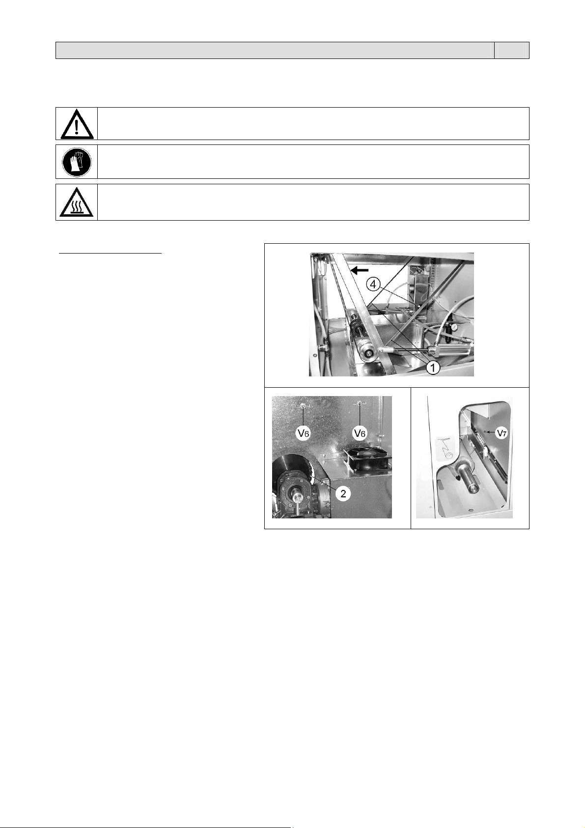
6.2. Verifica usura e livelli
Verificare periodicamente:
l’usura e la tensione delle cinghie di
Il livello dell’olio della vasca di compensazione
la tensione della catena di supporto degli
Durante le operazioni di manutenzione si consiglia di utilizzare guanti di protezione!
Prima di rimuovere il carter 9 (figura 1.3. pag.4) tenere conto di quanto segue:
se la macchina non è spenta da almeno 1 ora, il dispositivo di saldatura centrale può essere ancora
sufficientemente caldo da costituire pericolo di ustioni.
trasmissione 1 (figura A)
4.
Per controllare il livello reale dell’olio portare i
carrelli pinza a fine corsa come indicato nella
figura A dalla freccia.
Consigliamo di usare olio di tipo idraulico
ISO32.
spintori 2 (figura B).
La regolazione della tensione della catena si
effettua nel modo seguente:
allentare le viti V6 da un lato e dall’altro
(figura B)
tirare la catena svitando il tirante V7
(figura C).
A
B
C
6.3. Pulizia della macchina
Effettuare periodicamente:
una pulizia generale della macchina utilizzando un panno inumidito con acqua
una pulizia accurata delle lame saldanti delle pinze utilizzando un panno morbido
una pulizia giornaliera delle barre guida di scorrimento dei carrelli porta pinze che vanno pulite e lubrificate dalle
eventuali incrostazioni, con olio molto fluido (tipo idraulico)
una pulizia del tappeto togliendo eventuali residui di film induriti.
10

Capitolo 6. Manutenzione ordinaria IT
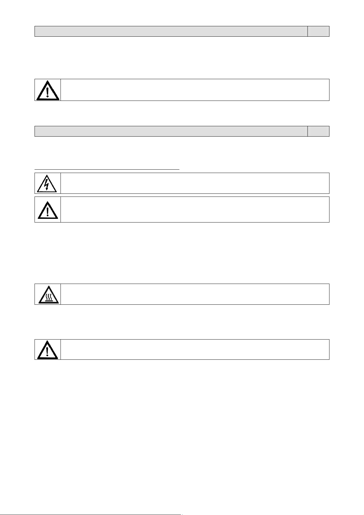
6.4. Sostituzione del colletto
Per effettuare il cambio del colletto C, procedere
come segue:
rimuovere il carter 9 (figura 1.3 pag.4)
svitare le 2 viti V1
rimuovere il colletto
inserire il nuovo colletto e fissarlo
riavvitando le viti V1
verificare la planarità del colletto e, se
necessario, ripristinarla svitando le 2 viti V2
e regolandola tramite i 3 grani V3. Serrare
quindi le viti V2
una volta sostituito il colletto, regolare
l’altezza dei deflettori D allentando la vite V4
in modo che siano circa 1mm più in basso
rispetto al colletto. Una volta posizionati
riavvitare la vite V4.
6.5. Sostituzione del cavo di alimentazione
ATTENZIONE!
Se il cavo di alimentazione è danneggiato, esso deve essere sostituito dal costruttore o dal suo servizio
assistenza tecnica, o comunque da una persona con qualifica similare, in modo da prevenire ogni rischio.
6.6. Schema elettrico (pagine 80 / 81 / 82).
Interruttore generale
Q1
Interruttore lampada
Q2
Fusibile linea
FU1
Fusibile trasformatore T1
FU2
Fusibile trasformatore T2
FU3
Fusibile ventilatore
FU4
Fusibile ventilatore
FU5
Fusibile ausiliario
FU6
Fusibile lampada
FU7
Fusibile scheda (generale)
F1
Fusibile scheda (resistenza saldatura centrale)
F2
Fusibile scheda (motore svolgitore bobina)
F3
Fusibile scheda (saldatura pinze)
F4
Trasformatore ausiliario emergenza/lampada
T1
Trasformatore ausiliario scheda
T2
Trasformatore saldatura pinza “A”
T3
Trasformatore saldatura pinza “B”
T4
Motore trasporto prodotti
M1
Motore pinze
M2
Ventilatore per M1
M3
Ventilatore per M2
M4
Ventilatore per M6
M5
Motore svolgitore bobina
M6
Lampada segnalazione tensione
P1
Lampada vano porta bobina
E1
Pulsante emergenza
S1
Filtro anti disturbo
V1
Contattore generale
QM1
Contattore per saldatore elettrostatico
QM2
Potenziometro regolazione pinze
R1
Resistenza valore minimo regolaz. pinze
R2
Potenziometro sbobinatore
R3
Resistenza saldatura pinza “A”
ER1
Resistenza saldatura pinza “B”
ER2
Resistenza saldatura centrale
ER3
G
B1
B2
B3
B4
B5
B6
B7
B8
B9
B10
B11
B12
B13
S2
QV1
QV2
QV3
QV4
QV5
QV6
QV7
U1
U2
TS1
TS2
K1
SK1
X1F
X1M
X2F
X2M
BT1
THV
LD
Encoder
Sensore magnetico passo trasporto
Sensore magnetico pinza “A” aperta
Sensore magnetico pinza “B” aperta
Sensore magnetico pinza “A” chiusa
Sensore magnetico pinza “B” chiusa
Sensore magnetico ritorno a zero pinza “A”
Sensore magnetico ritorno a zero pinza “B”
Finecorsa oltre corsa pinza “A”
Finecorsa oltre corsa pinza “B”
Finecorsa film teso
Finecorsa film lento
Finecorsa caricatore
Finecorsa portello superiore
Selettore a chiave esclusione sicurezza
Elettrovalvola apertura pinza “A”
Elettrovalvola apertura pinza “B”
Elettrovalvola chiusura pinza “A”
Elettrovalvola chiusura pinza “B”
Elettrovalvola ritorno pinza “A”
Elettrovalvola ritorno pinza “B”
Elettrovalvola saldatura centrale
Frizione avanzamento pinza “A”
Frizione avanzamento pinza “B”
Inverter
Inverter
Scheda IN/AUT
Scheda display
Connetore femmina x caricatore
Connetore maschio x caricatore (optional)
Connetore femmina x sbobinatore
Connetore maschio x sbobinatore
Termocoppia
Saldatore elettrostatico (optional)
Caricatore (optional)
11
Capitolo 6. Manutenzione ordinaria IT
6.7. Schema pneumatico (pagina 83).
6.8. Smontaggio, demolizione e smaltimento residui
Procedere nel seguente modo:
1. scollegare la macchina dalla rete di alimentazione elettrica;
2. smontare i componenti.
Ciascun rifiuto deve essere trattato, smaltito o riciclato in base alla classificazione ed alle procedure previste
dalla legislazione vigente nel paese di installazione.
Alimentazione aria
L
Cilindro apertura/chiusura pinza “A”
L1
Cilindro apertura/chiusura pinza “B”
L2
Cilindro ritorno carrello pinza “A”
L3
Cilindro ritorno carrello pinza “B”
L4
Cilindro sollevamento dispositivo di saldatura centrale
L5
Elettrovalvola apertura/chiusura pinza “A”
L6
Elettrovalvola apertura/chiusura pinza “B”
L7
Elettrovalvola ritorno carrello pinza ”A”
L8
Elettrovalvola ritorno carrello pinza ”B”
L9
Elettrovalvola sollevamento dispositivo di saldatura
L10
centrale
Riduttore di pressione pinze
L11
ATTENZIONE!
Le operazioni di smontaggio e demolizione devono essere affidate a personale specializzato a tali attività e
dotato delle competenze meccaniche ed elettriche necessarie a lavorare in condizioni di sicurezza.
Il simbolo indica che questo prodotto non deve essere trattato come rifiuto domestico.
Assicurando che il prodotto venga correttamente eliminato, si faciliterà la prevenzione di potenziali
conseguenze negative per l’ambiente e la salute dell’uomo, che potrebbero altrimenti essere causate da un
inappropriato trattamento del rifiuto di questo prodotto
Per informazioni più dettagliate riguardo il riciclaggio di questo prodotto, contattare il venditore del prodotto,
o in alternativa il servizio di post vendita o l’appropriato servizio di trattamento dei rifiuti.
L12
L13/14
L15
L16/17/18
Y1
Y2
Y3
Y4
Y5
Y6
Y7
S
Riduttore di pressione
Manometro
Filtro depuratore
Regolatore di flusso
Bobina apertura pinza “A”
Bobina apertura pinza “B”
Bobina chiusura pinza “A”
Bobina chiusura pinza “B”
Bobina ritorno carrello pinza “A”
Bobina ritorno carrello pinza “B”
Bobina sollevamento dispositivo di
saldatura centrale
Serbatoio olio ammortizzo
Capitolo 7. Garanzia IT
7.1. Certificato di garanzia
La Garanzia ha validità 12 mesi dalla data di installazione alle condizioni riportate sul libretto d’istruzioni. Compilare il
retro della cartolina in ogni sua parte, strappare lungo la linea e spedire.
7.2. Condizioni di garanzia
La garanzia è valida 12 mesi e decorre dalla data di installazione della macchina. La garanzia consiste nella sostituzione
o riparazione gratuita di tutte quelle parti riscontrate da noi difettose per anomalie di materiali. Le riparazioni o sostituzioni
avvengono normalmente presso la casa costruttrice con l’addebito all’acquirente delle spese di trasporto o manodopera.
Qualora le riparazioni o sostituzioni vengano eseguite presso la sede dell’acquirente, quest’ultimo sarà tenuto a pagare le
spese di viaggio, trasferta e manodopera. Le prestazioni di garanzia vengono eseguite esclusivamente a cura della casa
costruttrice o dal rivenditore autorizzato. Per avere diritto a prestazioni di garanzia inviare alla casa costruttrice od al
rivenditore autorizzato il pezzo difettoso, perché sia effettuata la riparazione o sostituzione. La riconsegna di tale pezzo
riparato o sostituito, rientrerà nell’adempimento delle operazioni di garanzia. La garanzia viene annullata:
1. per il mancato immediato invio postale del CERTIFICATO DI GARANZIA al momento dell’acquisto, debitamente
compilato e firmato entro 20 giorni;
2. per la errata installazione, la inadeguata alimentazione, negligenza d’uso e manomissione da parte di persone non
autorizzate;
3. per modifiche effettuate sulla macchina senza il consenso scritto della casa;
4. qualora la macchina non sia più proprietà del primo acquirente.
La casa costruttrice declina a termine di legge ogni responsabilità per danni a persone o cose qualora venga
effettuata un’errata installazione o collegamento alla rete di alimentazione elettrica o esclusione della messa a
terra od in caso di manomissioni della macchina stessa. La casa costruttrice si riserva di approntare modifiche
e cambiamenti secondo esigenze tecniche e di funzionamento.
PER QUALUNQUE CONTROVERSIA LEGALE
IL FORO COMPETENTE È QUELLO DI BERGAMO (ITALIA).
12

TRANSLATION OF THE
ORIGINAL INSTRUCTIONS
Index EN
Chapter 1. Description
1.1. Preface page 14
1.2. Machine technical data page 14
1.3. Machine description page 15
Chapter 2. Machine installation
2.1. Transport and positioning page 15
2.2. Environmental conditions page 15
2.3. Electrical connections page 16
2.4. Pneumatic connections page 16
Chapter 3. Machine adjustment and setting up
3.1. Control panel page 16
3.2. Film reel insertion page 17
3.3. Packaging page 18
3.4. Envelope and rear length adjustment page 18
3.5. Defects and possible remedies page 19
Chapter 4. Film features
4.1. Films to be used page 20
Chapter 5. Safety standards
5.1. General precautions page 20
5.2. Specific precautions page 20
Chapter 6. Ordinary maintenance
6.1. Precautions for ordinary maintenance interventions page 21
6.2. Wear check and levels page 21
6.3. Machine cleaning page 21
6.4. Forming box replacement page 22
6.5. Replacement of the supply cord page 22
6.6. Electrical diagram page 22
Pneumatic diagram page 23
6.7.
6.8. Disassembling, demolition and elimination of residuals page 23
Chapter 7. Guarantee
7.1. Certificate of guarantee page 23
7.2. Guarantee conditions page 23
EC declaration of conformity page 79
13
Chapter 1. Description EN
1.1. Preface
This manual has been drawn up in compliance with the UNI10893 standard dated July 2000. It is meant for all users in
order to enable them to use the machine correctly. Keep it in a place which can be easily accessed in the proximity of the
machine and which is known to all users. This manual is an integral part of the machine for safety reasons. We wish to
specify the symbols in use here below in order to improve understanding of them.
ATTENTION:
Accident prevention rules for the operator. This warning indicates the presence of dangers which
can injure the person operating on the machine.
ATTENTION:
Hot parts. Shows the danger of burning, thus involving the risk of a serious accident for the
exposed person.
WARNING:
It indicates the possibility of damaging the machine and/or its components.
ATTENTION:
Live devices: it shows an electrical danger involving the risk of a serious accident for the exposed
person.
ATTENTION:
Moving members: It shows the danger of coming into contact with moving members,thus involving
All reproduction rights of this manual are reserved to the manufacturer. Partial or complete reproduction is forbidden as
provided by the law. Descriptions and pictures provided in this manual are not binding. Therefore the manufacturer,
reserves the right to make any change considered necessary. This manual cannot be transferred for viewing to third
parties without authorisation in writing from the manufacturing company. The machine must be used only for the purpose
it was built for. Any other use shall be considered “improper” and therefore dangerous. Before carrying out any operation
on the machine it is compulsory to read carefully all instructions provided in this manual, in order to avoid possible
damage to the machine, to people and property.
Do not operate if in doubt about the correct interpretation of the instructions.
Contact the manufacturer in order to obtain the necessary explanation.
This machine is not intended for use by persons (including children) with reduced physical, sensory or mental
capabilities, or lack experience and knowledge, unless they have been given supervision or instruction concerning use of
the machine by a person responsible for their safety.
Children should be supervised to ensure that they do not play with the machine.
Upon delivery check that the machine is complete in all parts.
Possible faults shall be immediately reported to the manufacturer.
The manufacturing company declines any liability in case of machine improper use and/or in case of damage resulting
from operations carried out on the machine that are not mentioned in this manual.
1.2. Machine technical data
Package weight and sizes
Width = 2940mm / Length = 1500mm / Height = 1440mm
Weight = 605Kg
Machine weight and sizes
a = 2600mm
b = 960mm
c = 1160mm
Weight = 555Kg
the risk of a serious accident for the exposed person.
Electrical system
Voltage (V): see data on plate
Frequency (Hz): see data on plate
Maximum absorbed power (W): see data on plate
Maximum absorbed current (A): see data on plate
N.B.: When contacting the Manufacturer, always indicate the model and the serial number
specified on the plate on the rear part of the machine.
Air consumption: 40 litres/min. at 4 bar.
Maximum production: Plexi 30: 30 pieces/min., A4 format with a 25 micron polyethylene film.
Plexi 60: 60 pieces/min., A4 format with a 25 micron polyethylene film.
Size of material to be packed:
minimun A6
maximum A3 with maximum thickness 12mm.
14

5
Chapter 1. Description EN
1.3. Machine description
“Plexi” is an automatic horizontal envelope machine.
It may be used by inserting the magazines manually or by using the loaders which may be properly synchronised.
1 Main switch
2 Plug for interfacing with upstream devices
3 Electric supply cable
4 Control panel
5 Film reel area
6 Potentiometer to change the envelope length
7 Transversal welding area cover
8 Feet supporting adjustable side guides and relative lock
knobs
10 Magazines loading area
11 Auxiliary plug
12 Auxiliary plug controlled for optional devices
(electrostatic sealer)
13 Packed parcels unloading area
14 Compressed air connection
M Manometer.
Chapter 2. Machine installation EN
2.1. Transportation and positioning
It is recommended to handle with great care during transport and positioning!
To lift the machine, use a lift truck having an adeguate capacity (make sure the machine is properly balanced and pay
attention to the screws protruding from the lower part of the body). As an alternative provide for slinging and use a hoist
complete with ropes which are properly dimensioned and equipped with hooks at their end.
The machine is supplied with fixed feet. Never use the machine if it is arranged on wheels (its movement might alter ist
good operation).
2.2. Environmental conditions
Place the machine level on the floor in a suitable environment free from humidity, gases, explosives, combustible
Leave a minimum space of 0,5m around the machine so that not to obstruct air inlets.
Working environment conditions:
Temperature from + 5°C to + 40°C
Relative humidity from 30% to 90%, without condensation
The lighting of the operation room shall comply with the laws in force in the country where the machine is installed.
However, it shall be uniform and allow good visibility in order to safeguard the operator’s safety and health.
MACHINE PROTECTION FACTOR = IP20
THE AIRBORNE NOISE MADE BY THE MACHINE IS LOWER THAN 70 dB(A)
Use protection gloves while handling the machine.
materials. The machine may only be installed on smooth, flat non-inflammable surfaces.
1
6
Chapter 2. Machine installation EN
2.3. Electrical connections
OBSERVE HEALTH AND SAFETY REGULATIONS!
If the machine is not equipped with the power supply plug, use a plug that is suitable for the
voltage and amperage values described by the rating plate and that can comply with the
rules in force in the installation country.
GROUNDING OF THE UNIT IS OBLIGATORY!
Before making electrical connections, make sure the mains voltage matches the one on the
plate on machine rear and that the ground contact complies with the safety rules in force.
In case of doubts about the mains voltage, contact the local power supply company.
Insert the plug on the cable from machine electrical cabinet in a mains power supply socket
that can be reached easily by the operator.
2.4. Pneumatic connections
Connect the compressed air connection 14 (figure 1.3 page 15) at the exit of the machine. Use a pipeline having a
minimum diameter of 6 mm. and a 1/4” female union.
Chapter 3. Machine adjustment and setting up EN
3.1. Control panel
1. Display FN. Displays “J” (Jog) if manual or maintenance operations have been carried out on the machine, or if the
reset manoeuvre has not been carried out yet. To carry out the reset manoeuvre, press the START button. Displays
“A” (Automatic) if the machine is ready for to operate.
2. Display REAR. Displays the quantity of file behind the product.
3. Display LENGTH. Displays the length of the envelope.
4. Display CROSS SEAL. Displays the cross sealing temperature (pliers).
5. Display PCS MIN. Displays the number of envolopes produced per minute
6. Display TOTAL-CENTER SEALING. Displays the total number of envelopes produced. To reset, press and hold
the button (19).
7. Emergency button. Stops the machine immediately in the event of imminent danger or when selecting
maintenance mode. To release this button, rotate it counter-clockwise.
8. RESET button. For alarms E5, E6, E7, E12, and E13.
9. Activate pushers button. When the machine is stationary, press this button and the START button simultaneously
tom ove the pushers forward.
10. A pliers button. Press this button and button 9 simultaneously to open and close the A pliers.
11. B pliers button. Press this button and button 9 simultaneously to open and close the B pliers.
12. START button. Starts the packaging cycle.
Press once to set the machine to the START position.
Press again to start the packing cycle.
13. “DECREASE” button. Reduces the pliers sealing pulse duration (see note No.1).
14. “INCREASE” button. Increases the pliers sealing pulse duration (see note No.1).
15. STOP button. Stops the packaging cycle.
1
7
Chapter 3. Machine adjustment and setting up EN
16. “DECREASE” button. Reduces the number of pieces to be produced per minute (see note No.2).
17. “INCREASE” button. Increases the number of pieces to be produced per minute (see note No.2).
18. Central sealing temperature button. Press this button to visualise the central sealing temperature on the TOTAL-
CENTER SEALING display. The values are indicative and not expressed in degrees.
19. “DECREASE” button. Reduces the central sealing temperature.
Pressing this button also resets the piece counter (TOTAL-CENTER SEALING display).
20. “INCREASE” button. Increases the central sealing temperature.
21. RESET button. Press this button when the machine is switched on.
Resets the machine after an emergency stop button has been pressed.
22. Potentiometer. Enables the operator to regulate the length of the envelopes.
Note No.1: use the minimum “sealing time” necessary to seal the envelopes. Using longer times does not improve the
result, and causes the rubber belt to deteriorate more rapidly.
Note No.2: the optimal quantity of pieces per minute will depend upon the operator’s experience, the magazine
dimensions, the numbers of magazines that shall be inserted and the type of film in use.
3.2. Film reel insertion
Remove the fastening screw A.
Extract the unwinder B and insert the reel on the axis
of the unwinder by locking it with the centering cone
C.
Let the film run around the controlling dandy roll of
the unwinder (figure 1) as it is also shown by the
adhesive label D.
Manually move the film to the upper part of the
machine (figure 2).
Wind the “forming box” as required (figure 3).
Let the film run through the “forming box” so as to
place it over the idle belt (figure 4).
Lay the film carefully as specified by (figure 5).
Pull the film manually and check the position of the
upper and lower edge so as to form a tube.
1
4
2
5
3
1
8
Chapter 3. Machine adjustment and setting up EN
3.3. Packaging
Turn the main switch 1 into pos. 1.
Press button RESET. Press button START to start the machine.
Position the magazines manually in front of the pushers ensuring that the lateral guides are adjusted correctly.
The pushers feed the magazines into the film former (forming box) while they are sealed longitudinally by a sealing unit.
The envelopes will move along an idle belt dragged by 2 pliers which will alternatively provide for welding and cutting the
envelopes as well as unload them through the opening at the exit of the maschine.
The magazines can either be loaded manually or by using a
synchronised loading unit (optional).
The feeder is connected to the machine as follows:
connect the A (interfacing) cable with plug 1 (on the
feeder) and with plug 2 (on the machine)
connect the B (voltage) cable with plug 3 (on the feeder)
and with plug 11 (on the machine).
Plug 5 (on the feeder) will be of use if more than one feeder is
required to supply the machine. It is intended to connect in
series 2 feeders to each other or more than two feeders.
N.B.: if there is an extension installed
upstream of the machine, the machine
pushers must be synchronised with those
mounted on the extension.
Act as follows to regulate the exact position
from which the pushers shall start:
hold down button 9 “MANUAL”, press key
12 “START” to give short pulses in order
to bring any S pusher in a fall position
(figure 1)
adjust the dowel (V5) to position the
micro tracer point (figure 2).
1
2
3.4. Envelope and rear length adjustment
“ L ” Envelope length
“ X ” space directly related to “ L ”
“ Y ” rear.
The arrow will show the direction in which the product is
moving.
Envelope length
The envelope length can only be set up while the machine is moving.
Before providing for the adjustment, it is recommended to press buttons 8 - 9 at the same time to disable the micro switch
(slow film) (a lighted led on the 1 - FN display will show that the micro switch has been disabled).
Turn potentiometer 22 to adjust the length of the “ L ” envelope from 120 to 420 mm.
Turn it counterclockwise to lengthen the envelope. Turn it clockwise to shorten it.
The actual measurement expressed in millimetres will automatically appear in the “LENGTH” display (3). After
establishing the desired measurement and re-enabling the dandy roll micro switch (slow film), the machine is ready to
start packaging.
Rear
In order to regulate the length “ Y ”, use keys 10 and 11 to modify the value that appears in the REAR display.
This can be set to any value between 1 and 9 (each number is equivalent to approximately 2,2 mm).
Increase the value to increase the “ Y ” length and vice versa.
Set the “rear” value so that the envelope is sealed/cut at the mid-point between the two magazines.
1
Chapter 3. Machine adjustment and setting up EN
3.5. Defects and possible remedies
The display of the control panel may show some error codes which shall be interpreted according to the following table:
“ E ” flashing on display PCS-MIN = the step of the machine is not syncronized.
The electronic board is regularly sending the start command to the sealing guns, but these have not enough time to return to their “
zero position ”.
The machine keeps sealing, but cannot guarantee the correct size of the envelopes.
Decrease “ PCS – MIN ”.
Verify the sliding of the sealing gun trolleys.
Check the pressure on the manometer M (figure 1.3 page 15) the correct range is between 4 and 5,5 bar.
E0 = Welding lock
Power off the machine.
Check whether the supply lines of welding rods have short-circuited.
Check transformer T1 and T2.
Check the welding wire of pliers A and B.
Check the hot wire balancing spring of pliers A and B.
Check the board (call for assistance).
E01 = Alarm on pliers A (pliers A have required more than 2 seconds to open or close).
E02 = Alarm on pliers B (pliers B have required more than 2 seconds to open or close).
Power off the machine and check compressed air.
The manometer C shall show 2,2 bar.
A mechanical member of the pliers has jammed.
A thick magazine has got stuck in the pliers.
One of the two magnetic sensors has brocken down.
The magnet in the pliers shoulder can no longer hold its correct position or it can no longer
energise the sensor.
Call for assistance.
E03 = Both pliers in a 0 position
Power off the machine.
Move forward one of the 2 pliers manually.
Power on the machine.
Call for assistance.
E04 = Emergency, one two pliers has reached the micro switch of the limit stop
Remove the pliers from the limit stop. Power the machine off and on.
Decrease ” pezzi / min.” or “ lungh. / busta ”.
Check the operation of the limit stop.
E05 = Dandy roll micro switch
The film has loosened too much around the dandy roll.
The film reel is over. Replace it.
E06 = Door safety limit stop
Press (No.8).
Close the upper door. Check the door micro switch.
E07 = Wrong data have been stored, updated Eprom assembly
Press (No.8).
Check the board.
E08 = Sudden power failure
Check the mains voltage.
E09 = The max. passage time between one pusher and the next has been overcome
A fault of the pusher tow mechanism is likely.
Turn the machine off, check the magnet on the feeder control reduction gear.
E10 = Short-circuit on 24V dc output
Power off the machine.
Check the operation of the solenoid valves of electromagnetic couplings as well as other 24V users.
Call for assistance.
E11 = Inverter failure
Check the magazines feeder motor and chain.
Check the inverter. If required, replace.
Power the machine off and on.
E12 = The film is too stretched
The reel is over. Replace it.
Unwinder motor fault. Press (No.8).
E13 = The device for the automatIc insertion of magazines is empty
Press (No.8).
Check the loader.
19
Chapter 4. Film features EN
4.1. Films to be used
The machine can work with all heat-shrink and non-heat-shrink films (polyethlylene and polypropylene), from 15 to 30
microns in thickness, of a technical and food type. To guarantee the best results, use the films marketed by us.
The special features of our films (which may be customised with drawings and text) assure their outstanding reliability,
with regard both to compliance with laws in force and to excellent machine performance.
Consult the data and safety sheets of the films in use and observe the corresponding instructions!
Maximum reel width: 650mm
Chapter 5. Safety standard EN
5.1. General precautions
THE MACHINE CAN NOT BE USED BY UNTRAINED PERSONNEL!
Before acting on the machine to adjust, service and repair it:
put the machine in safe conditions by pressing the “emergency” button arranged on the control panel
power off the machine by turning the main switch to “0”
remove the supply plug.
5.2. Specific precautions
The welding pliers which will alternatively move will never reach a high temperature which may be considered as
dangerous. However, never touch the welding rod (or the hot wire) arranged beneath the lower profile of the welding
burner and hidden between the 2 film pressing slides. Pay great attention when you are working in the proximity of the
members above since there is the potential risk of accidentally coming into contact with very hot parts.
The device for the central welding will keep a higt temperature many minutes after the machine has been disabled and its
protections have been opened. Pay great attention when you are working in the proximity of the members above since
there is the potential risk of accidentally coming into contact with very hot parts (200°!).
The removal of cases, doors or walls in unsafe conditions may cause the operator/maintenance man to
come into contact with moving members, hot parts and live devices
If safety devices are either removed or tampered with by the user, this will relieve the supplier of any
civil and criminal liability.
It is recommended to use protection gloves.
The reset of the machine in automatic mode will necessarily require the inspection doors to be closed.
The machine is complete with a safety micro switch which will signal when the trasversal welding area cover 7 is open
(figure 1.3. page 15). This device will cause the machine to stop when the cover above is open.
In case of blocking of the machine or in order to stop it during the automatic cycle press the EMERGENCY
PUSHBUTTON (7).
Rotate clockwise to release and press the RESET button.
20

Chapter 6. Ordinary maintenance EN
6.1. Precautions for ordinary maintenance interventions
ORDINARY MAINTENANCE MUST BE CARRIED OUT BY QUALIFIED, APPROPRIATELY TRAINED STAFF.
Before proceeding to maintenance, switch the machine off and disconnect it by operating on the
master switch and wait for the machine to cool down!
6.2. Wear check and levels
Check as follows at regular intervals:
the wear and tension of driving belts 1 (figure
the oil level of the balancing tank 4.
It is recommended to use protection gloves during maintenance operations!
Before removing the case 9 (figure 1.3 page 15), never forget as follows:
if the machine was powered off at least 1 hour ago, the central welding device may still be hot
enough to represent a burning danger.
A)
Move the pliers carriages up to their stroke
end to check the actual oil level as it is shown
by the arrow of figure A.
it is recommended to use the oil of an ISO 32
hidraulic type.
A
the tension of the chain intended to support
the pushers 2 (figure B).
Act as follows to provide for its adjustment:
loosen the V6 screws from both sides
(figure B)
unscrew the V7 tie rod to pull the chain
(figure C).
B
C
6.3. Machine cleaning
Check as follows at regular intervals:
use a cloth to clean the machine after having dipped it into water
use a soft cloth to clean the welding blades of pliers carefully
clean the slide guides of the pliers carriages every day. Remove any incrustation and use a very thin oil (of a
hydraulic type) to lubrificate them
clean the belt and remove any film residual which have hardened.
21
Chapter 6. Ordinary maintenance EN
6.4. Forming box replacement
To replace the forming box C, act as follows:
remove the case 9 (figure 1.3 page 15)
unscrew the 2 screws
remove the forming box
insert the new forming box. Tighten the
screws V1 to fasten it
check that the new forming box is level and,
if necessary, correct it by adjusting the
dowels (V3) and screws (V2). Tighten the
fastening screws (V2) firmly
once the forming box has been replaced,
adjust the height of the deflectors (D) by
loosening the screw (V4) so that they are
approximately 1 mm lower than the forming
box. When they have been positioned
correctly, re-tighten the screw (V4).
6.5. Replacement of the supply cord
ATTENTION!
If the supply cord is damaged, it must be replaced by the manufacturer, its service agent or similarly qualified
persons in order to avoid a hazard.
6.6. Electrical diagram (page 80 / 81 / 82).
Q1
Q2
FU1
FU2
FU3
FU4
FU5
FU6
FU7
F1
F2
F3
F4
T1
T2
T3
T4
M1
M2
M3
M4
M5
M6
P1
E1
S1
V1
QM1
QM2
R1
R2
R3
ER1
ER2
ER3
Main switch
Lamp switch
Line fuse
Fuse for T1 transformer
Fuse for T2 transformer
Fuse for fan
Fuse for fan
Fuse auxiliary
Fuse for lamp
Board fuse (main)
Board fuse (central welding resistance)
Board fuse (unwinder motor)
Board fuse (pliers welding)
Auxiliary emergency/lamp transformer
Auxiliary board transformer
“A” plier welding transformer
“B” plier welding transformer
Product transport motor
Pliers motor
Fan for M1
Fan for M2
Fan for M6
Unwinder motor
Voltage signalling lamp
Reel-carrier compartment lamp
Emergency button
Antinoise filter
Main contactor
Contactor for electronic sealer
Pliers potentiometer
Heater minimum valve pliers setting
Unwinder potentiometer
“A” plier welding resistance
“B” plier welding resistance
Central welding resistance
G
B1
B2
B3
B4
B5
B6
B7
B8
B9
B10
B11
B12
B13
S2
QV1
QV2
QV3
QV4
QV5
QV6
QV7
U1
U2
TS1
TS2
K1
SK1
X1F
X1M
X2F
X2M
BT1
THV
LD
Encoder
Transport pitch magnetic sensor
Open “A” plier magnetic sensor
Open “B” plier magnetic sensor
Closed “A” plier magnetic sensor
Closed “B” plier magnetic sensor
“A” plier return to zero magnetic sensor
“B” plier return to zero magnetic sensor
“A” plier extra travel limit switch
“B” plier extra travel limit switch
Tensioned film limit switch
Slow film limit switch
Loader limit switch
Upper door limit switch
Safety override key
“A” plier opening solenoid valve
“B” plier opening solenoid valve
“A” plier closing solenoid valve
“B” plier closing solenoid valve
“A” plier return solenoid valve
“B” plier return solenoid valve
Central welding solenoid valve
“A” plier feed clucth
“B” plier feed clucth
Inverter
Inverter
IN/AUT board
Display board
Female connector for loader
Male connector for loader (optional)
Female connector for unwinder
Male connector for unwinder
Thermocouple
Electronic sealer (optional)
Feeder (optional)
22
Chapter 6. Ordinary maintenance EN
6.7. Pneumatic diagram (page 83).
L
L1
L2
L3
L4
L5
L6
L7
L8
L9
L10
L11
L12
L13
6.8. Disassembling, demolition and elimination of residuals
Proceed as follows:
1. disconnect machine from power mains
2. disassemble components
All wastes must be treated, eliminated or recycled according to their classification and to the procedures in
force established by the laws in force in the country where the equipment has been installed.
Air supply
“A” plier opening / closing cylinder
“B” plier opening / closing cylinder
“A” plier carriage return cylinder
“B” plier carriage return cylinder
Central welding device lifting cylinder
“A” plier opening / closing solenoid valve
“B” plier opening / closing solenoid valve
“A” plier carriage return solenoid valve
“B” plier carriage return solenoid valve
Central welding device lifting solenoid valve
Pliers pressure reducer
Pressure reducer
Manometer
ATTENTION!
All disassembling and demolition operations must be done by qualified personnel with mechanical and
electrical expertise required to work in safe conditions.
The symbol indicates that this product shall not be treated as household waste. By making sure that the
product will be properly disposed of, you will facilitate the prevention of potential negative effects for the
environment and human health, which might be otherwise caused by the improper waste treatment of this
product. For more detailed information about the recycling of this product, please contact the product
seller or, as an alternative, the after-sales service or the corresponding waste treatment service.
L14
L15
L16
L17
L18
Y1
Y2
Y3
Y4
Y5
Y6
Y7
S
Manometer
Cleaning filter
Flow regulator
Flow regulator
Flow regulator
“A” plier opening coil
“B” plier opening coil
“A” plier closing coil
“B” plier closing coil
“A” plier carriage return coil
“B” plier carriage return coil
Central welding device lifting coil
Damper oil tank
Chapter 7. Guarantee EN
7.1. Certificate of guarantee
The guarantee runs for 12 months after the installation date under the conditions set out in the instruction manual. Fill in
the card with all data requested, tear out along the perforations and send in.
7.2. Guarantee conditions
The guarantee runs for 12 months and comes into force on the installation date of the machine. The guarantee covers
free replacement or repair of any parts due to defects arising from faulty material. The repairs or replacement are usually
carried out at the manufacturer’s premises, with transport or labour charged to the buyer. If the repair or replacement is
carried out at the buyer’s premises, he shall bear the travelling, transfer and labour costs. Work under guarantee can be
carried out exclusively by the manufacturer or by the authorised dealer. In order to be entitled to repairs under the
guarantee, the faulty part must be sent for repair or replacement to the manufacturer or his authorised dealer. The return
of such repaired or replaced part will be considered fulfilment of the guarantee. The guarantee is voided:
1. in case of failure to mail the CERTIFICATE OF GUARANTEE, duly filled in and signed, with in 20 days after the date
of purchase.
2. in case of inappropriate installation, power supply, misuse and mishandling by unauthorised persons.
3. in case of changes made to the machine without prior agreement in writing from the manufacturer.
4. if the machine is no longer the property of the first buyer.
The manufacturer declines all liability for personal injury or damage in case of inappropriate installation or
connection to the power mains or omission of connection to earth or in case of any mishandling of the machine.
The manufacturer undertakes to carry out any variations and changes made necessary by technical and
operating requirements.
IN THE EVENT OF DISPUTES THE COURT OF BERGAMO (ITALY)
SHALL HAVE SOLE JURISDICTION.
23

ÜBERSETZUNG DER ORIGINAL-
ANLEITUNG
Inhaltsverzeichnis DE
Kapitel 1. Beschreibung
1.1. Vorwort Seite 25
1.2. Technische Daten der Maschine Seite 25
1.3. Beschreibung der Maschine Seite 26
Kapitel 2. Einbau der Maschine
2.1. Beförderung und Aufstellung Seite 26
2.2. Umweltbedingungen Seite 26
2.3. Elektrischer Anschluß Seite 27
2.4. Luftverbindung Seite 27
Kapitel 3. Einstellung und Vorbereitung der Maschine
3.1. Steuertafel Seite 27
3.2. Einlegen der Folienspule Seite 28
3.3. Verpacken Seite 29
3.4. Einstellen der Rear - und Tütenlänge Seite 29
3.5. Störungen und Behebung Seite 30
Kapitel 4. Merkmale der Folie
4.1. Zu verwendende Folien Seite 31
Kapitel 5. Sicherheitsvorschriften
5.1. Allgemeine Vorsichtsmassnahmen Seite 31
5.2. Spezifische Sicherheitsmassnahmen Seite 31
Kapitel 6. Ordentliche Wartung
6.1. Vorsichtsmaßnahmen für die ordentlichen Wartungsarbeiten Seite 32
6.2. Kontrolle von Verscheiß und Niveaus Seite 32
6.3. Reinigen der Maschine Seite 32
6.4. Austausch des Kragens Seite 33
6.5. Auswechseln des Stromversorgungskabels Seite 33
6.6. Schaltschema Seite 33
6.7. Pneumatikschema Seite 34
6.8. Abbau, Verschrottung und Entsorgung der Rückstände Seite 34
Kapitel 7. Garantie
7.1. Garantieschein Seite 34
7.2. Garantiebedingungen Seite 34
Konformitätserklärung Seite 79
24
Kapitel 1. Beschreibung DE
1.1. Vorwort
Das vorliegende Handbuch wurde gemäß den Norm UNI 10893 von Juli 2000 verfasst. Es richtet sich an alle Benutzer
und dient zur korrekten Bedienung der Maschine. Bewahren Sie es an einem leicht zugänglichen Ort in der Nähe der
Maschine auf, der allen Benutzern bekannt ist. Das vorliegende Handbuch ist in Bezug auf die Sicherheit ein
wesentlicher Teil der Maschine.
ACHTUNG:
Vorschriften zum Unfallschutz für den Bediener. Diese Warnung weist auf bestehende Gefahren
hin, die zu Verletzungen des Maschinenbedieners führen können.
ACHTUNG:
Heiße Maschinenteile. Zeigt eine Verbrennungsgefahr durch heiße Maschinenteile an, die für die
ausgesetzte Person auch schwerwiegend sein kann.
VORSICHT:
Weist auf die Gefahr hin, dass die Maschine bzw. deren Komponenten beschädigt werden
könnten.
ACHTUNG:
Gerät steht unter Strom: Zeigt eine für die ausgesetzte Person auch schwerwiegende Unfallgefahr
elektrischer Art an.
ACHTUNG:
Bewegliche Maschinenteile: Zeigt eine für die ausgesetzte Person auch schwerwiegende
Unfallgefahr durch Berührung mit beweglichen Maschinenteilen an.
Alle Rechte des vorliegenden Handbuchs sind dem Hersteller vorbehalten. Die Vervielfältigung, auch auszugsweise, ist
gesetzlich verboten. Die in diesem Handbuch enthaltenen Beschreibungen und Abbildungen sind unverbindlich. Der
Hersteller behält sich vor, jederzeit Änderungen vorzunehmen, die er als notwendig erachtet. Dieses Handbuch darf ohne
schriftliche Genehmigung des Herstellers nicht zur Einsicht an Dritte ausgehändigt werden. Die Maschine darf nur für
den vorgesehenen Anwendungszweck eingesetzt werden; jede andere Anwendung ist als „unsachgemäß“ und somit als
gefährlich anzusehen.
Vor Bedienung der Maschine müssen sorgfältig alle Hinweise in diesem Handbuch durchgelesen werden, um potentielle
Schäden an Maschine, Personen oder Gegenständen zu vermeiden.
Bei Zweifeln an der richtigen Auslegung der Hinweise darf die Maschine nicht betrieben werden.
Bitte wenden Sie sich für die notwendigen Erläuterungen an den Hersteller.
Die Maschine ist nicht dazu bestimmt, von Personen (einschließlich Kindern) angewandt zu werden, deren körperliche,
mentale oder Sinnesfähigkeiten eingeschränkt sind, oder die zu wenig Erfahrung oder Kenntnisse haben, außer wenn sie
durch eine Person, die für ihre Sicherheit verantwortlich ist, überwacht werden oder von dieser Anweisungen über den
Gebrauch des Geräts erhalten.
Kinder müssen ständig überwacht werden, um sicherzustellen, dass sie nicht mit der Maschine spielen.
Prüfen Sie bei der Auslieferung der Maschine, ob sie in allen ihren Teilen vollständig ist.
Eventuelle Auffälligkeiten müssen sofort dem Lieferanten mitgeteilt werden.
Der Hersteller lehnt jede Haftung für unsachgemäße Anwendung der Maschine und/oder Schäden ab, die auf Tätigkeiten
zurückzuführen sind, die nicht in diesem Handbuch vorgesehen sind.
1.2. Technische Daten der Maschine
Gewicht und Abmessungen der Verpackung
Breite = 2940mm / Länge = 1500mm / Höhe = 1440mm
Gewicht = 605Kg
Gewicht und Abmessungen der Maschine
a = 2600mm
b = 960mm
c = 1160mm
Gewicht = 555Kg
Zur besseren Verständlichkeit werden die verwendeten Symbole hier in der Folge erläutert.
Elektrische Anlage
Spannung (V): siehe Typenschild
Frequenz (Hz): siehe Typenschild
Maximale Leistungsaufnahme (W): siehe Typenschild
Maximale Stromaufnahme (A): siehe Typenschild
ANM.: Nennen Sie bitte bei jeglicher Kommunikation mit dem Hersteller immer das Modell
und die Seriennummer der Maschine, die auf dem Schild angegeben sind, das sich auf der
Rückseite der Maschine befindet.
Luftverbrauch: 40 l/min. bei 4 bar.
Höchstproduktion: Plexi 30: 30 St./min, Format A4 mit Polyäthylenfolie zu 25 Micron.
Plexi 60: 60 St./min, Format A4 mit Polyäthylenfolie zu 25 Micron.
Größe des zu verpackenden Materials:
Min. A6
Max A3 mit max.. Stärke 12mm
25

6
Kapitel 1. Beschreibung DE
1.3. Beschreibung der Maschine
“Plexi” ist ein horizontaler automatischer Eintüter. Die Zeitschriften können manuell oder mit Hilfe einer entsprechend
syncronisierten dafür vorgesehenen Ladevorrichtung eingeführt werden.
1 Hauptschalter
2 Schnittstelle mit anliegendem Gerät
3 Stromkabel
4 Schaltfeld
5 Bereich Folienrolle
6 Potentiometer zur Veränderung der Tütenlänge
7 Abdeckung des Querschweißbereichs
8 Stellfüße für einstellbare Seitenführungen mit
entsprechenden Sperrstiften
10 Zusatzstecker
11 gesteuerter Zusatzstecker für Optional
(elektrostatisches Schweißgerät)
12 Eingabebereich der Zeitschriften
13 Entnahmebereich der verpackten Pakete
14 Druckluftanschluss
M Manometer.
Kapitel 2. Einbau der Maschine DE
2.1. Beförderung und Aufstellung
Gehen Sie bei der Beförderung und beim Aufstellen der Maschine mit größter Vorsicht vor!
Die Maschine muss mit einem angemessenen Gabelstapler (auf das Gleichgewicht der Maschine und die im unteren
Gehäusebereich hervorstehenden Schrauben achten), bzw. vertäut durch ein angemessenes Kranfahrzeug mit korrekt
dimensionierten Seilen und Haken angehoben werden. Die Maschine wird mit festen Füßen geliefert und darf nicht auf
Räder gestellt werden (Verschiebungen könnten den Betrieb beeinträchtigen).
2.2. Umweltbedingungen
Das Gerät muss eben auf dem Boden aufgestellt werden, sowie in einer geeigneten Umgebung, die trocken ist und
Um die Maschine herum müssen mindestens 0,5m frei gelassen werden, damit die Lüfteröffnungen nicht verdeckt
Zulässige Umgebungsbedingungen am Aufstellungsort der Maschine:
Temperaturen zwischen + 5°C und + 40°C.
Relative Luftfeuchtigkeit zwischen 30 % und 90 %, ohne Kondensation.
Die Beleuchtung des Raums, in dem die Maschine benutzt wird, muss den Gesetzen entsprechen, die im Einbauland der
Maschine gelten und auf jeden Fall gleichmäßig sein und eine gute Sichtbarkeit gewährleisten, um die Sicherheit und die
Gesundheit des Bedieners zu schützen.
SCHUTZKLASSE DER MASCHINE = IP20
DAS VON DER MASCHINE ERZEUGTE LUFTGERÄUSCH LIEGT UNTER 70 dB(A)
Verwenden Sie beim Bewegen der Maschine Schutzhandschuhe.
in der sich keine brennbaren Gegenstände, Gase oder Sprengstoffe befinden. Die Maschine darf nur auf glatten,
ebenen und nicht entzündbaren Flächen aufgestellt werden.
werden.
2
7
Kapitel 2. Einbau der Maschine DE
2.3. Elektrischer Anschluß
BEACHTEN SIE DIE VORSCHRIFTEN ZUR SICHERHEIT AM
ARBEITSPLATZ!
Falls die Maschine nicht mit einem Netzstecker ausgestattet ist, verwenden Sie einen
Stecker, der den auf dem Typenschild angegebenen Spannungs- und Amperewerten und
den jeweiligen nationalen geltenden Bestimmungen entspricht.
DAS GERÄT DARF NICHT OHNE ERDUNG BETRIEBEN WERDEN!
Bevor Sie das Gerät an das Stromnetz anschließen, stellen Sie sicher, dass die Netzspannung der auf
dem Typenschild auf der Rückseite des Geräts angebenen Spannung entspricht und dass der
Erdungsanschluss den geltenden Sicherheitsvorschriften entspricht. Bei Zweifeln zur Netzspannung
kann das örtliche Elektrizitätswerk Auskunft geben.
Den Stecker des vom Schaltkasten der Maschine kommenden Kabels an eine bequem vom
Benutzer erreichbare Netzsteckdose anschließen.
2.4. Luftverbindung
Mit einer Leitung mit min. 6 mm Duchmesser und einem 1/4” Anschluss verbinden; der Druckluftanschluss befindet sich
auf der Ausgangsseite der Maschine 14 (Abbildung 1.3 Seite 26).
Kapitel 3. Einstellung und Vorbereitung der Maschine DE
3.1. Steuertafel
1. Display “FN”: zeigt “J” (Jog) an, wenn manuelle Handlungen oder Wartungsarbeiten an der Maschine verrichtet
wurden oder wenn der Resetvorgang noch nicht erfolgt ist. Für den Resetvorgang die Taste START drücken.
Display “FN”: zeigt “A” (Automatik) an, wenn die Maschine betriebsbereit ist.
2. Display “REAR”: zeigt die Folienmenge hinter dem Produkt an (jede Zahl entspricht ungefähr 2,2mm).
3. Display “LENGHT”: zeigt die Tütenlänge an (siehe Kapitel 5.5).
4. Display “CROSS SEAL”: zeigt die Temperatur der Querschweißung an (Zangen).
5. Display “PCS MIN”: zeigt die pro Minute produzierte Tütenzahl an.
6. Display “TOTAL-CENTER SEALING”: zeigt die Zahl der produzierten Tüten an.
Zum Rücksetzen die Taste (19) drücken.
7. Not-Aus-Taste.
Zum Anhalten des Verpackungszyklus drücken. Rücksetzen mit Taste RESET (21).
8. Taste Reset für Alarmmeldungen E5, E6, E7, E12, E13.
9. Taste zur Betätigung der Schieber bei angehaltener Maschine. Taste 9 + START drücken.
10. Taste Zange A. Durch gemeinsame Betätigung der Tasten 9+10 öffnet/schließt sich Zange A.
11. Taste Zange B. Durch gemeinsame Betätigung der Tasten 9+11 öffnet/schließt sich die Zange B.
12. START-Taste. Startet den Verpackungszyklus.
Einmal drücken, um die Maschine in die START-Position zu bringen.
Das zweite Mal drücken, um den Verpackungszyklus zu starten.
13. Taste „SENKEN”. Verringert die Zeit des Schweißimpulses der Zangen (siehe Hinweis Nr. 1).
14. Taste „ERHÖHEN”. Verlängert die Zeit des Schweißimpulses der Zangen (siehe Hinweis Nr. 1).
15. STOP-Taste. Hält den Verpackungszyklus an.
2

8
Kapitel 3. Einstellung und Vorbereitung der Maschine DE
16. Taste „SENKEN”. Verringert die Anzahl der pro Minute herzustellenden Stücke (siehe Hinweis Nr. 2).
17. Taste „ERHÖHEN”. Erhöht die Anzahl der pro Minute herzustellenden Stücke (siehe Hinweis Nr. 2).
18. Taste für zentrale Schweißtemperatur. Wenn man diese Taste drückt, wird am TOTAL-CENTER SEALING-
Display die Temperatur der zentralen Schweißung angezeigt. Die Werte sind ungefähr und nicht in Grad
ausgedrückt.
19. Taste „SENKEN”. Senkt die Temperatur der Zentralschweißung.
Außerdem setzt man durch Drücken dieser Taste den Stückzähler zurück (TOTAL-CENTER SEALING-Display).
20. Taste „ERHÖHEN”. Erhöht die Temperatur der Zentralschweißung.
21. RESET-Taste. Ist bei Einschalten der Maschine zu drücken.
Stellt die Maschine nach Ansprechen des Not-Aus-Tasters wieder zurück.
22. Potenziometer. Ermöglicht die Einstellung der Tütenlänge.
Hinweis Nr.1: Verwenden Sie die niedrigste „Schweißzeit”, die nötig ist, um das Schweißen der Tüte zu erreichen.
Längere Zeiten ergeben kein besseres Ergebnis, sondern nutzen das Gummiband früher ab.
Hinweis Nr.2: Die optimale Stückzahl pro Minute ist abhängig von: Erfahrung des Bedieners, Größe der Zeitschrift,
Zahl der einzufügenden Zeitschriften, verwendeter Folientyp.
3.2. Einlegen der Folienspule
Nach Ausstellen der Maschine die Feststellschraube
A entfernen.
Den Abwickler B entnehmen und die
Feststellschraube A festschrauben. Die Rolle auf den
Dorn des Abwicklers stecken und mit dem
Zentrierkegel C.
Die Folie um die Vordruckwalze des Abwicklers
(Abbildung 1) führen, wie auf dem Schild angegeben
D.
Die Folie von Hand in den oberen Maschinenbereich
führen (Abbildung 2).
Die Folienmeßvorrichtung entsprechend einstellen
(Abbildung 3).
Die Folie durch die Öffnungen bis auf das Laufband
führen (Abbildung 4).
Die Folie sorgfälting ausbreiten, siehe (Abbildung 5).
Von Hand die Folie ziehen und prüfen, dass die
obere und untere Lasche einen Schlauch bilden.
1
4
2
5
3
2

Kapitel 3. Einstellung und Vorbereitung der Maschine DE
3.3. Verpacken
Der Hauptschalter 1 auf Pos. 1 stellen.
RESET drücken. START drücken, um die Maschine zu starten.
Die Zeitschriften von Hand vor die Schieber legen; die Seitenführungen müssen entsprechend reguliert sein.
Die Schieber schieben die Zeitschriften in die Folienfalteinrichtung (Kragen), während die Längsnaht geschweißt wird.
Die auf einem frei laufenden Laufband liegenden Tüten werden durch 2 Zangen gezogen, die abwechselnd auch das
Schweißen und Schneiden der anschließend aus der Öffnung am Maschinenauslauf ausgestoßenen Tüten vornehmen.
Die Zeitschriften können von Hand aber auch mit Hilfe von
entsprechend synchronisierten Aufgabevorrichtungen zugeführt
werden (optional).
Der Anschluss des Anlegers an die Maschine erfolgt
folgenderweise:
kabel A (Schnittstelle) an Steckdose 1 (Anleger) und an
Steckdose 2 (Maschine) anschließen
kabel B (Stromversorgung) an Steckdose 3 (Anleger) und
an Steckdose 11 (Maschine) anschließen.
Das Kabel 5 (Anleger) dient für den Fall, dass mehrere Anleger
die Maschine versorgen; hierdurch können 2 oder mehr Anleger
in Serie angeschlossen werden.
Anmerkung: Ist der Maschine ein
Verlängerungssystem vorgeschaltet ist,
müssen die Schieber der Maschine mit
denen des Verlängerungssystems
synchronisiert werden.
Um die genaue Startposition der Schieber
einzustellen, folgendermaßen vorgehen:
die taste 9 “MANUAL” gedrückt halten
und mit Taste 12 “START” kurze Impulse
geben, bis ein beliebiger Schieber S die
Fallposition erreicht (Abbildung 1)
anschließend den Taster des Mikroschalters
durch den Stift V5 positionieren (Abbildung 2).
1
2
3.4. Einstellen der Rear - und Tütenlänge
“ L ” Tütenlänge
“ X ” direkt an “ L ” gebundener Bereich
“ Y ” rear.
Der Pfeil zeigt die Laufrichtung des Produkts an.
Tütenlänge
Die Tütenlänge kann nur bei laufender Maschine eingestellt werden.
Vor der Einstellung sollte der Mikroschalter (Folie langsam) durch gleichzeitiges Drücken der Tasten 8 - 9 deaktiviert
werden (ein LED auf Display 1 - FN weist auf die Deaktivierung hin).
Die Tütenlänge “ L ” von 120 bis 420 mm wird durch Drehen des Potentiometers 22 eingestellt.
Gegen den Uhrzeigersinn zur Verlängerung, mit dem Uhrzeigersinn zur Verkürzung der Tüten.
Auf dem Display 3 “LENGTH” erscheint automatisch die eingestellte Länge in mm. Nach Einstellung der Länge und
Aktivierung des Mikroschalters (Folie langsam) der Andruckrolle, ist die Maschine betriebsbereit.
Rear
Zum Einstellen der Länge “ Y ” den am Display REAR angezeigten Wert mit den Tasten 10 und 11 ändern.
Werte von 1 bis 9 können nicht eingestellt werden (jeder Zahl entspricht ca. 2,2mm).
Durch Erhöhen des Werts wird “ Y ” verlängert und umgekehrt.
Die Funktion “rear” so einstellen, dass das Schweißen/Schneiden der Tüten in der Mitte von zwei Zeitschriften erfolgt.
29

0
Kapitel 3. Einstellung und Vorbereitung der Maschine DE
3.5. Störungen und Behebung
Auf dem Display des Schaltfelds können Fehlercodes erscheinen, die folgendermaßen zu verstehen sind:
“ E ” leuchtet auf LED-Anzeiger “ PCS – MIN ” = die Maschinenteilung ist nicht mehr synchronisiert.
Die Platine sendet regelmäßig den Schweißzangen die Startsteuerung, aber sie haben nicht Zeit genug, in der Nullstellung
zurückzukehren.
Die Maschine läuft noch, kann aber nicht die genaue Umschlagsgröße gewährleisten.
Der Wert “ PCS – MIN ” reduzieren.
Die Wagengleitung der Zangen prüfen.
Der Druck des Manometer M (Abbildung 1.3 Seite 26) nachprüfen: er sollte zwischen 4 und 5,5 bar liegen.
E0 = Schweißen blockiert
Die Maschine abschalten.
Nach eventuellen Kurzschlüssen der Stromversorgung der Schweißleisten suchen.
Die Trafos T1 und T2 prüfen.
Die Schweißleisten der Zangen A und B prüfen.
Die Ausgleichsfeder des heißen Drahts der Zangen A und B prüfen.
Die Schaltkarte prüfen (Hilfsdienst benachrichtigen).
E01 = Alarm an Zange A (das Öffnen und Schließen der Zange A dauert mehr als 2 Sekunden).
E02 = Alarm an Zange B (das Öffnen und Schließen der Zange B dauert mehr als 2 Sekunden).
Die Maschine abschalten und die Druckluft prüfen:
Das Manometer C muss 2,2 bar anzeigen.
Ein mechanisches Element der Zange ist blockiert.
Eine dicke Zeitung hat sich in der Zange verklemmt.
Einer der beiden Magnetsensoren ist beschädigt.
Der in der Zangenseite eingesetzte Magnet befindet sich auf einer falschen Position und
spricht den Sensor nicht mehr an.
Den Hilfsdienst benachrichtigen.
E03 = Beide Zangen befinden sich jeweils auf Position 0
Die Maschine abschalten.
Eine der beiden Zangen von Hand vorschieben.
Die Maschine wieder einschalten.
Den Hilfsdienst benachrichtigen.
E04 = Notfal, eine der beiden Zangen hat den Mikroschalter des Endanschlags erreicht
Die Zange vom Endanschlag entfernen. Die Maschine aus-und erneut einschalten.
“ pezzi / min ” ober “ lungh ./ busta ” verringern.
Funktionskontrolle des Endanschlags.
E05 = Mikroschalter der Vordruckwalze
Die Folie hat sich an der Walz gelöst.
Die Folienrolle ist leer. Austauschen.
E06 = Endschalter Klappensicherung
(Nr.8) drücken.
Die obere Klappe schließen.
Den Mikroschalter der Klappe prüfen.
E07 = Es wurden falsche Daten gespeichert, neue Eprom montiert
(Nr.8) drücken.
Die Schaltkarte prüfen.
E08 = Plötzlicher Stromausfall.
Die Netzspannung prüfen.
E09 = Die max Laufzeit zwischen einen Schubschlepper und den nächste wurde übersteigert.
Man nimmt einen Defekt von den Schleppergetriebe an.
Die Maschine ausschalten. Den Magnet von den Speisersteuer-Untersetzungsgetriebe nachprüfen.
E10 = Kurzschluß im 24V dc output
Die Maschine ausschalten.
Funktion der Elekroventile der elektromagnetischen Kupplungen und der anderen 24V-Geräte prüfen.
Den Hilfsdienst benachrichtigen.
E11 = Fehler Inverter
Motor und Zuführsequenz der Zeitschriften prüfen.
Inverter prüfen und gegebenenfalls austauschen.
Die Maschine aus-und erneut einschalten.
E12 = Folie zu straff
Die Rolle ist leer, austauschen.
Der Abwicklermotor ist defekt, (Nr.8) drücken.
E13 = Automatische Zeitschriftenzuführung leer
(Nr.8) drücken.
Die Ladevorrichtung prüfen.
3

Kapitel 4. Merkmale der Folie DE
4.1. Zu verwendende Folien
Die Maschine kann mit allen wärmeschrumpfenden und nicht wärmeschrumpfenden Folien (PE oder PP) mit einer Stärke
von 15 bis 30 Mikron arbeiten, sowohl mit technischen Folien als auch mit Lebensmittelfolien. Um optimale Ergebnisse
zu garantieren, wird empfohlen, die von uns vermarkteten Folien zu verwenden.
Die besonderen Eigenschaften unserer Folien (auch personalisierte Abbildungen und Schriftzüge unserer Kunden) sind
eine Garantie für die Zuverlässigkeit, sowohl in Hinsicht auf die Übereinstimmung mit den bestehenden Vorschriften als
auch in Hinsicht auf die Sicherheit und das bestmögliche Funktionieren unserer Maschinen.
Es wird dringend dazu geraten, die technischen und Sicherheitsblätter der verwendeten Folien
durchzulesen und sich an die darin beschriebenen Vorgaben zu halten!
Max Rollenbreite: 650mm.
Kapitel 5. Sicherheitsvorschriften DE
5.1. Allgemeine Vorsichtsmassnahmen
NICHT AUSGEBILDETEM PERSONAL DARF DIE ANWENDUNG DER MASCHINE NICHT GESTATTET WERDEN!
Vor inbetriebnahme der Maschine für Einstellungen, Wartung und Reparaturen:
die Maschine durch Drücken der “Nottaste” auf dem Schaltfeld sichern
die Stromverbindung durch Drehen des Hauptschalters auf “0” unterbrechen
den Stecker ziehen.
5.2. Spezifische Sicherheitsmassnahmen
Die abwechselnd beweiglichen Schweißzangen erreichen niemals eine als gefährlich zu betrachtende Temperatur. Es
sollte dennoch darauf geachtet werden, dass die unter dem unteren Profil der Schweißlasche, zwischen den beiden
Folienandruckschlitten, angebrachte Schweißleiste (oder der heiße Draht) nicht mit den Fingern berührt wird. Daher
sollte bei Arbeiten nahe dieser Bauteile höchste Vorsicht herrschen, da Berührungsgefahr sehr heißer Elemente besteht.
Die mittlere Schweißvorrichtug besitzt hingenen nach Abschalten der Maschine und Öffnen der Schutzvorrichtungen für
mehrere Minuten eine sehr hohe Temperatur, weshalb höchste Vorsicht herrschen sollte, wenn in der Nähe dieser
Bauteile Arbeiten durchzurührungsgefahr mit Elementen, die bis zu (200°C!) heiß sind.
Das Entfernen von Gehäusen, Klappen oder Wänden unter unsicheren Bedingungen kann den
Bediener/Wartungspersonal mit beweglichen, heißen oder unter Strom stehenden Teilen in Kontakt
bringen
Das Entfernen oder Manipulieren von Sicherheitsvorrichtungen seitens des Bedieners enthebt den
Hersteller von jeglicher straf-/zivilrechtlicher Verantwortung.
Es wird das Tragen von Schutzhandschuhen empfohlen.
Der Reset der Maschine in den automatischen Zyklus erfolgt erst nach Schließen eventuell geöffneter Kontrollklappen.
Die Maschine ist mit einem Sicherheits-Mikroschalter ausgestattet, der das Öffnen der Abdeckung im
Querschweißbereich anzeigt 7 (Abbildung 1.3. Seite 26). Diese Vorrichtung unterbricht bei Öffnen der Abdeckung jede
Bewegung der Maschine.
Falls die Maschine stoppt oder Sie sie während des automatischen Arbeitszyklus anhalten möchten,
drücken Sie auf die NOT-AUS-TASTE (7).
Die Taste zum Ausrasten im Uhrzeigersinn drehen und RESET drücken.
31

Kapitel 6. Ordentliche Wartung DE
6.1. Vorsichtsmaßnahmen für die ordentlichen Wartungsarbeiten
DIE ORDENTLICHE WARTUNG MUSS VON QUALIFIZIERTEN UND ENTSPRECHEND EINGEWIESENEN
FACHKRÄFTE VORGENOMMEN WERDEN.
Bevor Sie mit den Wartungsarbeiten beginnen, schalten Sie die Maschine über den Hauptschalter
aus, ziehen Sie den Stecker aus der Netzsteckdose und warten Sie, bis sich die Maschine abgekühlt
hat!
6.2. Kontrolle von Verschleiß und Niveaus
Regelmäßig prüfen:
verschleiß und Spannung der Antriebsriemen
őlstand im Ausgleichsbehälter 4.
Es wird empfohlen, bei den Wartungsarbeiten Schutzhandschuhe zu tragen!
Vor Entfernen des Gehäuses 9 (Abbildung 1.3 Seite 26) folgendes berücksichtigen:
Wurde die Maschine vor weniger als einer Stunde abgeschaltet, kann die mittlere
Schweißvorrichtung noch heiß genug sein, um eine Verbrennungs-gefahr darzustellen.
1 (Abbildung A)
Zur Kontrolle des tatsächlichen Ölniveaus die
Zangenschlitten zum Anschlag führen (siehe
Pfeil auf -Abbildung A).
Hydrauliköl der Sorte ISO 32 verwender.
A
spannung der Schieberketten 2 (Abbildung B).
Die Einstellung erfolgt folgendermaßen:
die beiden Schrauben V6 voneinander
lösen (Abbildung B)
spanner V7 aufschrauben und die Kette
spannen (Abbildung C).
B
C
6.3. Reinigen der Maschine
Regelmäßig durchführen:
allgemeine Reinigung der Maschine mit einem mit Wasser befeuchteten Lappen
gründliche Reinigung der Schweißmesser der Zangen mit einem weichen Tuch
die Führungsschienen der Zangenschlitten täglich mit sehr flüssigem Öl (Hydrauliköl) von eventuellen Ablagerungen
reinigen und schmieren
reinigung des Teppichs von harten Folienresten.
32

Kapitel 6. Ordentliche Wartung DE
6.4. Austausch des Kragens
Den Kragen C folgendermaßen austauschen:
das Gehäuse entfernen 9 (Abbildung 1.3
Seite 26)
die beiden Schrauben V1 lösen
den Kragen entfernen
den neuen Kragen einsetzen und durch
Festziehen der beiden Schrauben V1
befestigen
den waagrechten Einbau des Kragens
prüfen und bei Bedarf die 2 Fixierschrauben
V2 lösen, mit den 3 Stellschrauben V3
justieren und die Fixierschrauben V2 wieder
festziehen
Nach dem Austausch des Kragens die Höhe
der Lenkbleche D durch Lockern der
Schraube V4 justieren. Sie müssen
ungefähr 1 mm niedriger als der Kragen
stehen. Danach die Schraube V4 wieder
festziehen.
6.5. Auswechseln des Stromversorgungskabels
ACHTUNG!
Wenn das Stromversorgungskabel beschädigt ist, muss es vom Hersteller oder von dessen Kundendienst
ausgewechselt werden, oder zumindest von einer Person mit gleichwertiger Qualifikation, um jegliche
Gefahr zu meiden.
6.6. Schaltschema (Seite 80 / 81 / 82).
Q1
Q2
FU1
FU2
FU3
FU4
FU5
FU6
FU7
F1
F2
F3
F4
T1
T2
T3
T4
M1
M2
M3
M4
M5
M6
P1
E1
S1
V1
QM1
QM2
R1
R2
R3
ER1
ER2
ER3
Hauptschalter
Lichtschalter
Liniensicherung
Sicherung für Transformator T1
Sicherung für Transformator T2
Ventilator- Sicherung
Ventilator- Sicherung
Hilfs Sicherung
Sicherung für Lampe
Sicherung Karte (Haupt)
Sicherung Karte (Zentralschweißung – Widerstand)
Sicherung Karte (Abroller-Motor)
Sicherung Karte (Schweißung Zangen)
Hilfstransformator Notstand/Lampe
Hilfstransformator Karte
Transformator Schweissung “A” Zange
Transformator Schweissung “B” Zange
Produktentransportmotor
Zange-motor
Ventilator für M1
Ventilator für M2
Ventilator für M6
Abroller-Motor
Spannungsanzeigelampe
Lampe für Spulentüröffnung
Notschalter
Störungshemmender Filter
Hauptkontaktgeber
Kontaktgeber für elektrostatisches Schweißgerät
Zange-Potentiometer
Widerstand min.Wert Zangeneinstellung
Abroller- Potentiometer
Widerstand Schweißung “A” Zange
Widerstand Schweißung “B” Zange
Zentralschweißung - Widerstand
G
B1
B2
B3
B4
B5
B6
B7
B8
B9
B10
B11
B12
B13
S2
QV1
QV2
QV3
QV4
QV5
QV6
QV7
U1
U2
TS1
TS2
K1
SK1
X1F
X1M
X2F
X2M
BT1
THV
LD
Encoder
Magnetischer Sensor Transportschritt
Magnetischer Sensor “A” Zange offen
Magnetischer Sensor “B” Zange offen
Magnetischer Sensor “A” Zange geschlossen
Magnetischer Sensor “B” Zange geschlossen
Magnetischer Sensor Nullpunktrücklauf
Magnetischer Sensor Nullpunktrücklauf
A Zange
B Zange
Endanschlag “A” Zangen-Uberlauf
Endanschlag “B” Zangen-Uberlauf
Film Endanschlag “A” gespannt
Film Endanschlag “B” langsanm
Beladevorrichtung Endanschlag
Endanschlang obere Abdeckplatte
Sicherheits-Ausschließungs-Schlüssel
Elektroventil “A” Zange Öffnung
Elektroventil “B” Zange Öffnung
Elektroventil “A” Zange Schließung
Elektroventil “B” Zange Schließung
Elektroventil “A” Zangenrücklauf
Elektroventil “B” Zangenrücklauf
Elektroventil Zentralschweißung
Vorschubskupplung “A” Zange
Vorschubskupplung “B” Zange
Inverter
Inverter
Karte IN/OUT
Display Karte
Beladevorrichtung-Verbinder Nut
Beladevorrichtung-VerbinderFeder (optional)
Abroller-Verbinder Nut
Abroller-Verbinder Feder
Sonde
Elektrostatisches Schweißgerät (optional)
Anleger (optional)
33

Kapitel 6. Wartung DE
6.7. Pneumatikschema (Seite 83).
L
L1
L2
L3
L4
L5
L6
L7
L8
L9
L10
L11
L12
L13
Luftzuführung
Zylinder für Öffnung / Schließung A-Zange
Zylinder für Öffnung / Schließung B-Zange
Zylinder für Schlittenrücklauf A-Zange
Zylinder für Schlittenrücklauf B-Zange
Zylinder für Zentralschweißung-Hebevorrichtung
Elektroventil für Öffnung / Schließung A-Zange
Elektroventil für Öffnung / Schließung B-Zange
Elektroventil für Schlittenrücklauf A-Zange
Elektroventil für Schlittenrücklauf B-Zange
Elektroventil für Zentralschweißung-Hebevorrichtung
Zangen-Druckreduzierer
Druckreduzierer
Manometer
L14
L15
L16
L17
L18
Y1
Y2
Y3
Y4
Y5
Y6
Y7
S
Manometer
Reinigungsfilter
Flussregler
Flussregler
Flussregler
Spule für Öffnung A-Zange
Spule für Öffnung B-Zange
Spule für Schließung A-Zange
Spule für Schließung B-Zange
Spule für Schlittenrücklauf A-Zange
Spule für Schlittenrücklauf B-Zange
Spule für Zentralschweißung-Hebevorrichtung
Tank für Stossdämpferöl
6.8. Abbau, Verschrottung und Entsorgung der Rückstände
ACHTUNG!
Die Abbau- und Verschrottungsarbeiten dürfen nur von Personen durchgeführt werden, die auf diese
Tätigkeiten spezialisiert sind und die zum sicheren Arbeiten notwendigen mechanischen und elektrischen
Fachkenntnisse besitzen.
Gehen Sie folgendermaßen vor:
1. Trennen Sie die Maschine vom Stromnetz.
2. Bauen Sie die Bestandteile auseinander.
Alle Abfälle müssen entsprechend der Klassifizierung und den Vorgehensweisen, die von den im
Installationsland geltenden Gesetzen vorgeschrieben sind, behandelt, entsorgt oder wiederverwertet werden.
Das Symbol weist darauf hin, dass dieses Produkt nicht als Hausmüll behandelt werden darf.
Indem Sie sicherstellen, dass das Produkt ordnungsgemäß entsorgt wird, helfen Sie, die Umwelt und die
Gesundheit der Menschen vor möglichen negativen Folgen zu schützen, die verursacht werden könnten,
wenn die Abfälle dieses Produkts nicht sachgemäß behandelt werden. Für nähere Informationen über das
Recycling dieses Produkt setzen Sie sich bitte mit dem Verkäufer des Produkts in Verbindung oder auch mit
dem Kundendienst bzw. der entsprechende Stelle für die Müllbehandlung.
Kapitel 7. Garantie DE
7.1. Garantieschein
Die Garantie gilt für den Zeitraum von 12 Monaten ab dem Datum der Aufstellung zu den in der Bedienungsanleitung
angegebenen Bedingungen. Füllen Sie die Rückseite der Garantiekarte vollständig aus, schneiden Sie sie entlang der
perforierten Linie ab und schicken Sie sie uns.
7.2. Garantiebedingungen
Die Garantie gilt für den Zeitraum von 12 Monaten ab dem Datum der Aufstellung der Maschine. Sie erstreckt sich auf den kostenlosen
Austausch oder die Reparatur all jener Teile, die wir aufgrund von Werkstoffanomalien als fehlerhaft einstufen. Die Reparaturen bzw.
der Austausch werden normalerweise im Werk des Herstellers vorgenommen, wobei der Käufer die Transportkosten und den
Arbeitslohn trägt. Sollte die Reparatur oder der Austausch beim Käufer vorgenommen werden, so trägt dieser die Reisekosten, das
Tagegeld und den Arbeitslohn. Die Garantieleistungen werden ausschließlich durch den Hersteller oder durch autorisierte Fachhändler
durchgeführt. Um ein Anrecht auf Garantieleistungen zu haben, muss das defekte Teil dem Hersteller oder dem autorisierten
Fachhändler zugeschickt werden, damit die Reparatur oder der Austausch vorgenommen werden können. Die Rücklieferung eines
solchen reparierten oder ausgetauschten Teils fällt unter die Erfüllung der Garantieleistungen. Die Garantie verfällt in folgenden Fällen:
1. Wenn die GARANTIEURKUNDE nicht innerhalb von 20 Tagen nach Erwerb des Geräts vollständig ausgefüllt und unterschrieben
per Post verschickt wird.
2. Wenn das Gerät falsch aufgestellt, falsch versorgt oder durch nicht autorisierte Personen fahrlässig bedient oder gehandhabt wird
oder Änderungen daran vorgenommen werden.
3. Wenn am Gerät vom Hersteller ohne die schriftliche Genehmigung des Herstellers Veränderungen vorgenommen werden.
4. Wenn sich das Gerät nicht mehr im Besitz des ersten Käufers befindet.
Der Hersteller weist aufgrund bestehenden Rechts jede Haftung für Schäden an Personen oder Dingen zurück, wenn das Gerät
falsch aufgestellt oder falsch an das Stromnetz oder ohne Erdung angeschlossen wurde oder wenn Änderungen an der
Maschine vorgenommen wurden. Der Hersteller behält sich das Recht vor, aus technischen oder funktionellen Gründen
Änderungen am Gerät vorzunehmen.
FÜR JEGLICHEN RECHTSSTREIT
IST DAS GERICHT BERGAMO (ITALIEN) ZUSTÄNDIG.
34

TRADUCTION DES INSTRUCTIONS
ORIGINALES
Table des matières FR
Chapitre 1. Description
1.1. Preface page 36
1.2. Caractéristiques techniques page 36
1.3. Description de la machine page 37
Chapitre 2. Installation de la machine
2.1. Transport et levage page 37
2.2. Conditions ambiantes page 37
2.3. Raccordement électrique page 38
2.4. Raccordement pneumatique page 38
Chapitre 3. Réglage et mise en service
3.1. Panneau de commande page 38
3.2. Installer et amorcer la bobine de film page 39
3.3. Effectuer l’emballage page 40
3.4. Réglage longueur enveloppe et rear page 40
3.5. Inconvénients et remèdes possibles page 41
Chapitre 4. Caractéristiques du film
4.1. Films admissibles page 42
Chapitre 5. Normes de sécurité
5.1. Précautions générales page 42
5.2. Précautions spécifiques page 42
Chapitre 6. Entretien ordinaire
6.1. Précautions pour les interventions d’entretien ordinaire page 43
6.2. Vérification usure et niveaux page 43
6.3. Nettoyage de la machine page 43
6.4. Remplacement embase page 44
6.5. Remplacement du câble d’alimentation page 44
6.6. Schéma électrique page 44
6.7. Schéma pneumatique page 45
6.8. Démontage, démolition et mise à la décharge page 45
Chapitre 7. Garantie
7.1. Certificat de garantie page 45
7.2. Conditions de garantie page 45
Declaration CE de conformité page 79
35

6
Chapitre 1. Description FR
1.1. Preface
Ce manuel a été rédigé dans le respect de la norme UNI 10893 du mois de juillet 2000. Il s’adresse à tous les utilisateurs
afin de permettre une bonne utilisation de la machine. Conservez-le dans un lieu facile d’accès, à proximité de la
machine et connu de tous les utilisateurs. Ce manuel fait partie intégrante de la machine en matière de sécurité. Pour
améliorer sa compréhension, nous précisons ci-après les symboles utilisés.
ATTENTION:
Normes de prévention contre les accidents du travail. Cet avertissement indique la présence de
dangers pouvant provoquer des blessures à la personne qui travaille sur la machine.
ATTENTION:
Organes chauds. Indique un danger de brûlures avec risque d’accident, voire même grave, pour la
personne exposée.
AVERTISSEMENT:
Indique la possibilité de dommages pouvant être causés à la machine et/ou à ses composants.
ATTENTION:
Appareils sous tension: indique un danger de nature életrique avec risque d’accident, même grave,
pour la personne exposée.
ATTENTION:
Organes en mouvement: indique un danger de contact avec des organes en mouvement avec
Tous les droits de reproduction de ce manuel sont réservés à la société constructrice. La reproduction, même partielle,
est interdite conformément à la loi. Les descriptions et les illustrations présentes dans ce manuel ne sont pas
contraignantes et par conséquent, la société constructrice se réserve le droit d’apporter à n’importe quel moment toutes
les modifications qu’elle retiendra opportunes. Ce manuel ne peut être cédé à des tiers sans l’autorisation écrite de la
société de construction de la machine. La machine ne doit être utilisée que pour satisfaire les exigences pour lesquelles
elle a été conçue, tout autre utilisation doit être considérée comme "usage impropre ”, et donc dangereux.
Avant d’entreprendre une quelconque opération sur la machine, il est obligatoire de lire attentivement toutes les
instructions de ce manuel afin d’éviter de possibles dommages à la machine, aux personnes et aux choses.
Il est interdit d’utiliser la machine en cas de doutes sur la correcte interprétation des instructions.
Faire appel au fabricant pour obtenir les éclaircissements nécessaires.
L’utilisation de la machine est interdite aux enfants et aux adultes ne jouissant pas de toutes leurs capacités physiques,
sensorielles ou mentales; la machine ne peut non plus être utilisée par des personnes sans expérience, à moins qu’ils ne
bénéficient, à travers l’intermédiation d’une personne responsable de leur sécurité, d’une surveillance ou d’instructions
relatives à son utilisation.
Les enfants doivent être surveillés pour s’assurer qu’ils ne jouent pas avec la machine.
Au moment de la livraison, vérifier si la machine est complète.
Les éventuelles anomalies devront être signalées immédiatement au fournisseur.
La société constructrice décline toute responsabilité en cas d’usage impropre de la machine et/ou en cas de dommages
causés à la suite d’opérations non prévues dans ce manuel.
1.2. Caractéristiques techniques
Poids et dimensions de l’emballage
Largeur = 2940mm / Longueur = 1500mm / Hauteur = 1440mm
Poids = 605Kg
Poids et dimensions de la machine
a = 2600mm
b = 960mm
c = 1160mm
Poids = 555Kg
risque d’accident, même grave, pour la personne exposée.
Installation électrique
Tension (V): voir plaquette
Fréquence (Hz): voir plaquette
Puissance maximum absorbée (W): voir plaquette
Intensité maximale (A): voir plaquette
N.B.: Quand vous nous contactez, citez toujours le modèle et le numéro de série indiqués sur la
plaquette apposée sur la partie arrière de la machine.
Consommation air: 40 litres/min à 4 bars.
Production maximale: Plexi 30: 30 pièces/min format A4 avec film en polyéthylène de 25 microns.
Plexi 60: 60 pièces/min format A4 avec film en polyéthylène de 25 microns.
Dimensions matériel à envelopper:
minimal A6
maximal A3 avec épaisseur maximale 12mm.
3

7
Chapitre 1. Description FR
1.3. Description de la machine
La “Plexi” est une enveloppeuse horizontale automatique.
Elle peut être utilisée en introduisant manuellement les revues on en utilisant des chargeurs synchronisés.
1 Interrupteur général
2 Prise interface avec dispositif en amont
3 Câble d’alimentation électrique
4 Panneuau de commandes
5 Zone bobine film
6 Potentiomètre pour la variation de la longueur de
l’enveloppe
7 Couvercle zone soudure transversale
8 Pieds d’appui guides latéraux réglables et relatives
poignées de blocage
10 Prise auxiliaire
11 Prise auxiliaire commandée en option (soudeur
électrostatique)
12 Zone chargement revues
13 Zone déchargement paquets enveloppés
14 Raccordement air comprimé
M Manomètre.
Chapitre 2. Installation de la machine FR
2.1. Transport et levage
Pour le transport et le levage de la machine, il est recommandé d’opérer avec beaucoup de
prudence!
Procéder au soulèvement avec un chariot élévateur approprié à la charge (faire attention à l’équilibrage de la machine et
aux vis dépassant dans la partie inférieure de la carrosserie) ou dans l’alternative avec élingage et moyen de
soulèvement approprié avec câbles aux bonnes dimensions et équipés de crochets à leurs extrémités.
La machine est équipée avec des pieds fixes; ne pas utiliser la machine si elle se trouve positionée sur des roues (les
déplacements peuvent compromettre son bon fonctionnement).
2.2. Conditions ambiantes
Assurez-vous que la machine est à niveau dans un milieu ambiant sans humidité, sans matériaux inflammables, ni
Laissez 0,5m minimum d’espace autour de la machine pour ne pas colmater les prises d’air.
Conditions ambiantes admissibles:
Température de + 5°C à + 40°C
Humidité relative de 30% à 90% sans condensation
L’éclairage du local doit être conforme aux lois en vigueur dans le pays où la machine est installée ; il doit être uniforme
et garantir une bonne visibilité pour a sécurité et la santé de l’opérateur.
DEGRÉ DE PROTECTION DE LA MACHINE = IP20
LE BRUIT PRODUIT PAR LA MACHINE EST INFÉRIEUR À 70 dB(A)
Portez des gants de protection pour le levage de la machine.
gaz, ni matériaux explosibles. La machine doit être installée uniquement sur un sol lisse, à niveau et non
inflammable.
3

8
Chapitre 2. Installation de la machine FR
2.3. Raccordement électrique
RESPECTEZ LES CONSIGNES DE SECURITE SUR LE LIEU DE TRAVAIL!
Si la machine ne possède pas de fiche d’alimentation, utilisez une fiche adaptée aux
valeurs de tension et d’intensité mentionnées sur la plaquette signalétique et conforme aux
normes en vigueur dans le pays d’installation.
LA MISE À TERRE DE LA MACHINE EST OBLIGATOIRE!
Avant de brancher la machine, assurez-vous que la tension de réseau corresponde à la
tension indiquée sur la plaquette apposée sur la partie arrière de la machine et que le
contact de terre soit conforme aux consignes de sécurité en vigueur. En cas de doutes sur
la tension, contactez votre distributeur d’énergie électrique.
Brancher la fiche du câble en provenance du tableau électrique de la machine dans une
prise de courant du circuit général, qui soit facile à atteindre par l’opérateur.
2.4. Raccordement pneumatique
Raccorder avec une tuyaterie ayant un diamètre minimal de passage de 6 mm et un raccord femelle de 1/4”, le
branchement d’air comprimé 14 (figure 1.3 page 37) placé sur le côté sortie de la machine.
Chapitre 3. Réglage et mise en service FR
3.1. Panneau de commande
1. Afficheur “FN”: il affiche “J” (Jog) si des opérations manuelles ou d’entretiens ont été effectuées sur la machine,
ou bien si la manœuvre de raz n’a pas encore été effectuée. Pour effectuer la manœuvre de raz, presser le bouton
START. Afficheur “FN”: il affiche “A” (Automatique) si la machine est prête à fonctionner.
2. Afficheur “REAR”: il affiche la quantité de film derrière le produit (chaque numéro correspond environ à 2,2mm).
3. Afficheur “LENGHT”: il affiche la longueur de l’enveloppe (voir rubrique 5.5).
4. Afficheur “CROSS SEAL”: il affiche la température du soudage transversal (pinces).
5. Afficheur “PCS MIN”: il affiche la quantité d’enveloppes produites par minute.
6. Afficheur “TOTAL-CENTER SEALING”: il affiche la quantité d’enveloppes produites.
Pour remettre à zéro, maintenir le bouton (19) pressé.
7. Bouton d’arrêt d’urgence. Presser pour arrêter le cycle de condionnement. Pour remettre à zéro, presser le
bouton RESET (21).
8. Bouton d’effacement des alarmes E5, E6, E7, E12, E13.
9. Bouton pour actionner les pousseurs avec la machine à l’arrêt. Presser le bouton 9 + START pour faire
avancer les pousseurs.
10. Bouton pince A. Si on presse simultanément les boutons 9+10, la pince A s’ouvre et se ferme.
11. Bouton pince B. Si on presse simultanément les boutons 9+10, la pince B s’ouvre et se ferme.
12. Bouton START. Pour démarrer le cycle de conditionnement.
Presser une première fois pour mettre la machine en position de START.
Presser une seconde fois pour commencer le cycle de conditionnement.
13. Bouton “DECREMENTER”. Réduire la durée de l’impulsion de scellage des pinces (voir note n°1).
14. Bouton “INCREMENTER”. Augmenter la durée de l’impulsion de scellage des pinces (voir note n°1).
15. Bouton ARRET. Arrêter le cycle de conditionnement.
3

Chapitre 3. Réglage et mise en service FR
16. Bouton “DECREMENTER”. Réduire le nombre de pièces à produire par minute (voir note n°2).
17. Bouton “INCREMENTER”. Augmenter le nombre de pièces à produire par minute (voir note n°2).
18. Bouton température soudure centrale. Presser ce bouton pour faire apparaître, sur l’afficheur TOTAL-CENTER
SEALING la température de la soudure centrale. Les valeurs sont indicatives et ne sont pas exprimées en degrés.
19. Bouton “DECREMENTER”. Réduire la température de la soudure centrale.
Presser ce bouton pour effacer le compteur de pièces (afficheur TOTAL-CENTER SEALING).
20. Bouton “INCREMENTER”. Augmenter la température de la soudure centrale.
21. Bouton RAZ. Presser à la mise sous tension de la machine.
Réinitialise la machine après l’intervention du bouton d’arrêt d’urgence.
22. Potentiomètre. Permet le réglage de la longueur de sachets.
Note N.1: utiliser le “temps de soudure” minimum nécessaire pour obtenir la soudure du sachet. Un temps élevé
n’améliore pas le résultat ma détériore de manière précoce la bande en caoutchouc.
Note N.2: la quantité optimale de pièces par minute dépend de: l’expérience de l’opérateur, des dimensions de la
revue, du nombre de revues à introduire, du type de film utilisé.
3.2. Installer et amorcer la bobine de film
Elever les vis de fixage A.
Retirer le dérouleur B. Introduire la bobine sur l’axe
du dérouleur en la bloquant avec le cône centreur C.
Faire passer le film autour de la tige baladeuse de
commande du dérouleur (figure 1) comme cela est
aussi indiqué sur la plaque adhésive D.
Porter manuellement le film dans la partie supérieure
de la machine (figure 2).
Enrouler le conformateur de façon appropriée (figure
3).
Faire passer le film à travers les embases jusqu’a ce
qu’il se trouve au-dessus du tapis fou (figure 4).
Étendre soigneusement le film comme indiqué (figure
5).
Tirer manuellement le film et contrôler la position des
deux extrémités inférieure et supérieure jusqu’à la
formation du tube.
1
4
2
5
3
39

0
Chapitre 3. Réglage et mise en service FR
3.3. Effectuer l’emballage
Tourner l’interrupteur général 1 dans la position 1.
Appuyer sur le bouton RESET. Appuyer sur le bouton START pour faire démarrer la machine.
Placer à la main les revues devant les pousseurs avec les guides latéraux réglés.
Les pousseurs introduisent les revues à l’intérieur du conformateur du film (embase) pendant qu’un dispositif effectue la
soudure longitudinale.
Les enveloppes avancent sur un tapis entraîné par 2 pinces qui, par l’intermédiaire d’un mouvement alterné, effectuent la
soudure et la coupe des enveloppes en les expulsant ensuite par l’ouverture de sortie de la machine.
Le positionnement des revues peut être manuel mais peut aussi
avoir lieu à l’aide de chargeurs synchronisés (optional).
Le raccordement du chargeur à la machine se fait de la façon
suivante:
raccorder le câble A (de mise en interface) à la prise 1 (sur
le chargeur), et à la prise 2 (sur la machine)
raccorder le câble B (de tension), à la prise 3 (sur le
chargeur), et à la prise 11 (sur la machine).
La prise 5 (sur le chargeur)sert au cas où il faudrait plus d’un
chargeur pour alimenter la machine; elle permet de raccorder
en série entre eux 2 ou plusieurs chargeurs.
N.B.: si une rallonge est installée en amont
de la machine, il est nécessaire de mettre
en phase les pousseurs de la machine
avec ceux de la rallonge.
Pour régler la position exacte de départ des
disposeurs opérer comme ci-après:
tenir la touche 9 “MANUAL” appuyée et
avec la touche 12 “START” donner de
petites impulsions pour porter un
quelconque disposeur S en position de
chute (figure 1)
positionner le tâteur en agissant sur le
boulon V5 (figure 2).
1
2
3.4. Réglage longueur enveloppe et rear
“ L ” longueur de l’enveloppe
“ X ” espace directement relié à “ L ”
“ Y ” rear.
La flèche indique la direction de déplacement du produit.
Longueur de l’enveloppe
Le réglage de la longueur de l’enveloppe peut être effectuée uniquement avec la machine en marche.
Avant d’effectuer la réglage il est indispensable de désactiver le micro-interrupteur (film lent) en appuyant simultanément
sur les touches 8 - 9 (un voyant lumineux sur le display 1 - FN en indique l’exclusion).
La longueur de l’enveloppe “ L ”, de 120 à 420 mm se règle en tournant le potentiomètre 22.
En le tournant dans le sens contraire aux aiguilles d’une montre l’enveloppe s’allonge; en le tournant dans le sens des
aiguilles d’une montre l’enveloppe se raccourcit.
Sur le display 3 “LENGTH” apparaît automatiquement la mesure effective en millimètres. Une fois la mesure établie,
après avoir réinitialisé le micro-interrupteur (film lent) de la tige baladeuse, la machine est prête à procéder à l’emballage.
Rear
Pour régler la longueur “ Y ”, modifier la valeur affichée sur le display REAR, à l’aide des touches 10 et 11.
Il est possible de sélectionner une valeur de 1 à 9 (chaque numéro correspond environ à 2,2mm).
En augmentant la valeur, on augmente la longueur de la queue “ Y ” et vice-versa.
Paramétrer “rear” pour que la soudure et la coupe de l’enveloppe aient lieu à distance égale des deux revues.
4

Chapitre 3. Réglage et mise en service FR
3.5. Inconvénients et remèdes possibles
Sur le display du panneau de commandes apparaissent des codes d’erreur qui doivent être interprétés en fonction du tableau suivant:
“ E ” clignotant sur le display PCS - MIN = le pas de la machine n’est plus synchronisé.
La carte électronique envoie régulièrement la commande de départ aux pinces mais elles n’arrivent pas à retourner en position
zéro.
La machine continue à produire mais elle n’est plus en function de garantir la mesure exacte des enveloppes.
Diminuer “ PCS – MIN ”.
Contrôler le déplacement des chariots des pinces.
Contrôler la pression du manomètre M (figure 1.3 page 37) de 4 à 5,5 bars.
E0 = Blocage soudure
Éteindre la machine.
Contrôler les éventuels courts-circuits sur les lignes d’alimentation des barres soudantes.
Contrôler le transformateur T1 et T2.
Contrôler le fil soudante de la pince A et B.
Contrôler le ressort de compensation du fil chaud de la pince A et de la pince B.
Contrôler la carte (faire appel à l’assistance).
E01 = Alarme sur pince A (le mouvement d’overture ou de fermeture de la pince A a duré plus de 2 secondes).
E02 = Alarme sur pince B (le mouvement d’overture ou de fermeture de la pince B a duré plus de 2 secondes).
Éteindre la machine et contrôler l’air comprimé.
Le manomètre C doit indiquer 2,2 bars.
Un organe mécanique de la pince est bloqué.
Une revue de grosse épaisseur est restée bloquée dans la pince.
Un des deux capteurs magnétiques s’est cassé.
Le magnéto se trouvant dans l’épaulement de la pince n’est plus dans sa correcte position ou
ne parvient pas à exciter le capteur.
Faire appel à l’assistance.
E03 = Les deux pinces se trouvent en position 0
Éteindre la machine.
Déplacer manuellement en avant une des 2 pinces.
Rallumer la machine.
Faire appel à l’assistance.
E04 = Urgence, une des 2 pinces a atteint le micro-interrupteur de fin de couse
Enlever la pince du fin de course. Éteindre et rallumer la machine.
Diminuer “ piéces / min ” ou “ longeur / enveloppe ”.
Contrôler le fonctionnement du fin de course.
E05 = Micro-interrupteur de la tige baladeuse
Le film s’est trop détendu autour de la tige baladeuse.
La bobine du film est finie. La remplacer.
E06 = Fin de course sûreté trappe
Appuyer (sur N°8).
Fermer la trappe supérieure.
Contrôler le micro-interrupteur de la trappe.
E07 = De fausses données ont été mémorisées, montage Eprom ajourné
Appuyer sur (N°8).
Contrôler la carte.
E08 = Chute de tension imprévue
Contrôler la tension du réseau.
E09 = Temp maximal dépassé entre le passage d’un disposeur et l’autre
Possibilité de panne aux mécanismes d’entraînement des disposeurs.
Éteindre la machine, contrôler les magnétos sur le réducteur de commande de l’alimentation.
E10 = Court-circuit sur 24V cc output
Éteindre la machine.
Contrôler le fonctionnement des électrovannes des embrayages électromagnétiques et des autres utilisations 24V.
Faire appel à l’assistance.
E11 = Anomalie Variateur
Contrôler le moteur et la chaîne de l’alimentateur de revues.
Contrôler le variateur, le remplacer éventuellement.
Éteindre et rallumer la machine.
E12 = Film trop tendu
La bobine est finie. La remplacer.
Panne au moteur du dérouleur. Appuyer sur (N°.8).
E13 = Dispositif automatique d’insertion de revues vide
Appuyer sur (N°8).
Contrôler le chargeur.
41

Chapitre 4. Caractéristiques du film FR
4.1. Films admissibles
La machine peut usiner tous les films thermorétractables ou non (polyéthylène et polypropylène) dont l'épaisseur est
comprise entre 15 et 30 microns, de type technique et alimentaire. Pour obtenir le meilleur résultat, il est conseillé
d'utiliser les films que nous commercialisons.
Nos films (y compris ceux avec dessins et textes personnalisés) possèdent des caractéristiques spéciales qui
garantissent la fiabilité que ce soit du point de vue de la conformité aux réglementations en vigueur, que du point de vue
de l’assurance d’un excellent fonctionnement de nos machines.
Il est recommandé de consulter les fiches techniques et de sécurité des films utilisés et d’observer
les prescriptions reportées!
Largeur maximale de la bobine: 650mm.
Chapitre 5. Normes de sécurité FR
5.1. Précautions générales
NE PERMETTEZ PAS AU PERSONNEL NON FORME D’UTILISER LA MACHINE!
Avant d’intervenir sur la machhine pour des réglages, l’entretien et des réparations:
5.2. Précautions spécifiques
Les pinces à souder à mouvement alterné n’atteignent jamais une température élevée pouvant être dangereuse; faire
néanmoins attention à ne pas toucher avec les doigts la barre soudante (ou le fil chaud) placée sous le profil inférieur du
bec soudant, cachée entre les deux glissières presse-film. Prêter donc la plus grande attention quand on opère à
proximité de ces organes car il existe un risque potentiel de contact accidentel avec des parties très chaudes.
Le dispositif de soudure centrale garde au contraire une température élevée pendant plusieurs minutes après la
désactivation de la machine et l’overture des relatives protections; prêter donc la plus grande attention quand on opère à
proximité de cet organe car existe un risque potentiel de contact accidentiel avec des paraties très chaudes (200°!).
mettre la machine en état de sûreté en appuyant sur la touche “urgence” placée sur le panneau de commandes
enlever la tension en mettant l’interrupteur général en position “0”
enlever la fiche d’alimentation.
L’enlèvement de carters, de trappes ou de cloisons en absence de sécuritè peut exposer
l’opérateur/préposé à l’entretien à des contacts avec des organes en mouvement, des parties chaudes
et des appareillages sous tension
L’enlèvement des dispositifs de sécurité ou leur endommagement de la part de l’utilisateur, libère le
fournisseur de toute responsabilité pénale et civile.
Il est conseillé d’utiliser des gants de protection.
La réinitialisation de la machine en cycle automatique implique formellement la fermeture des éventuels trappes
d’inspection.
La machine est équipée d’un micro-interrupteur de sûreté qui signale l’overture du couvercle de la zone soudure
tranversale 7 (figure 1.3. page 37).
Ce dispositif interrompt tout mouvement de la machine à l’overture du couvercle.
En cas de blocage de la machine ou pour l’arrêter durant le cycle automatique, appuyez sur le BOUTON
ARRET D’URGENCE (7).
Pour le débloquer il faut le tourner dans le sens des aiguilles d’une montre et appuyer sur le bouton
RESET.
42

Chapitre 6. Entretien ordinaire FR
6.1. Precautions pour les interventions d’entretien ordinaire
L’ENTRETIEN ORDINAIRE DOIT ÊTRE EFFECTUÉ PAR DU PERSONNEL QUALIFIE ET EXPRESSEMENT FORME.
Avant d’effectuer l’entretien de la machine, éteignez-la avec l’interrupteur général, ôtez la fiche de la
prise d’alimentation et attendez qu’elle se refroidisse!
6.2. Vérification usure et niveaux
Vérifier périodiquement:
l’usure et la tension des courroies de
le niveau de l’huile de la cuve de
La tension de la chaîne de support des
Il est recommandé de porter des gants pour effectuer l’entretien!
Avant d’enlever le carter 9 (figure 1.3 page 37) tenir compte de ce qui suit:
si la machine n’est pas éteinte depuis au moins 1 heure, le dispositif de soudure centrale peut être
encore suffisamment chaud pour présenter un danger de brûlures.
transmission 1 (figure A)
compensation 4.
Pour contrôler le niveau réel de l’huile, porter
les chariots pince en fin de course comme
cela est indiqué avec la flèche dans la figure
A.
Nous conseillons l’utilisation d’huiles de type
hidraulique ISO 32
disposeurs 2 (figure B).
Le réglage de la tension de la chaîne
s’effectue de la façon suivante:
desserrer les vis V6 d’un côté et de
l’autre (figure B)
tirer la chaîne en vissant la tirant V7
(figure C).
A
B
C
6.3. Nettoyage de la machine
Effectuer périodiquement:
un nettoyage général de la machine en utilisant un chiffon humidifié avec de l’eau
un nettoyage soigné des lames soudantes des pinces en utilisant un chiffon doux
un nettoyage quotidien des barres guide de déplacement chariots porte-pinces qui doivent être nettoyées de leurs
éventuelles incrustations et lubrifiées avec de l’huile très fluide (type hydraulique)
un nettoyage du tapis pour éliminer les résidus durcis de films.
43

Chapitre 6. Entretien ordinaire FR
6.4. Remplacement embase
Pour effectuer le changement de l’embase C
procéder de la façon suivante:
enlever le carter 9 (figure 1.3 page 37)
dévisser les 2 vis V1
enlever l’embase
introduire la nouvelle embase et la fixer en
vissant les vis V1
vérifier la planéité de l’embase et, si cela est
nécessaire, agir sur les 3 boulons
appropriés V3 et sur les 2 vis V2. Serrer les
vis V2
L’embase remplacée, régler la hauteur des
déflecteurs D en desserrant la vis V4 de
manière à ce qu’ils soient 1 mm plus bas
environ que l’embase.Le réglage terminé,
revisser la vis V4.
6.5. Remplacement du câble d’alimentation
ATTENTION !
Si le câble d’alimentation est abîmé, il doit être remplacé par le Constructeur ou par son service
d’assistance technique, ou du moins par une personne possédant le même niveau de qualification, de
manière à prévenir le moindre risque d’accident.
6.6. Schéma électrique (page 80 / 81 / 82).
Interrupteur général
Q1
Interrupteur lampe
Q2
Fusible de ligne
FU1
Fusible de tranformateur T1
FU2
Fusible de tranformateur T2
FU3
Fusible ventilateur
FU4
Fusible ventilateur
FU5
Fusible auxiliaire
FU6
Fusible lampe
FU7
Fusible platine electronique (général)
F1
Fusible platine electronique (résistance soudure central)
F2
Fusible platine electronique (moteur dérouleur bobine)
F3
Fusible platine electronique (soudure pinces)
F4
Tranformateur auxiliaire
T1
Tranformateur auxiliaire platine
T2
Tranformateur de soudure “A”
T3
Tranformateur de soudure “B”
T4
Moteur transport produits
M1
Moteur pinces
M2
Ventilateur pour M1
M3
Ventilateur pour M2
M4
Ventilateur pour M6
M5
Moteur dérouleur bobine
M6
Lampe signalation de tension
P1
Lampe éclairage dérouleur
E1
Touche d’urgence
S1
Filtre Antibrouillage
V1
Contacteur général
QM1
Contacteur pour soudeur électrostatique
QM2
Potentiomètre réglage pinces
R1
Résistance valeur min. réglage pinces
R2
Potentiomètre dérouleur
R3
Résistance de soudure pince “A”
ER1
Résistance de soudure pince “B”
ER2
Résistance de soudure central
ER3
Encodeur
G
Captuer magnétique pas trasport
B1
Captuer magnétique pince “A” ouverte
B2
Captuer magnétique pince “B” ouverte
B3
Captuer magnétique pince “A” fermée
B4
Captuer magnétique pince “B” fermée
B5
Captuer magnétique retour au zéro pince “A”
B6
Captuer magnétique retour au zéro pince “B”
B7
Interrupteur fin de course pince “A”
B8
Interrupteur fin de course pince “B”
B9
Interrupteur fin de course film tendu
B10
Interrupteur fin de course film lâche
B11
Interrupteur fin de course chargeur
B12
Interrupteur fin de course porte supérieure
B13
Sélecteur a clé exclusion sécurité
S2
Soupape overture pince “A”
QV1
Soupape overture pince “B”
QV2
Soupape fermeture pince “A”
QV3
Soupape fermeture pince “B”
QV4
Soupape retour pince “A”
QV5
Soupape retour pince “B”
QV6
Soupape soudure centrale
QV7
Embrayage avancement pince “A”
U1
Embrayage avancement pince “B”
U2
Inverter
TS1
Inverter
TS2
Platine IN/AUT
K1
Platine display
SK1
Connecteur femelle pour chargeur
X1F
Connecteur mâle pour chargeur (accessoire)
X1M
Connecteur femelle pour dérouleur
X2F
Connecteur mâle pour dérouleur
X2M
Thermocouple
BT1
Soudur élecrostatique (accessoire)
THV
Chargeur (accessoire)
LD
44

5
Chapitre 6. Entretien ordinaire FR
6.7. Schéma pneumatique (page 83).
L
L1
L2
L3
L4
L5
L6
L7
L8
L9
L10
L11
L12
L13
Alimentation air
Cylindre ouverture / fermeture pince A
Cylindre ouverture / fermeture pince B
Cylindre retour chariot pince A
Cylindre retour chariot pince B
Cylindre soulèvement dispositif de soudure centrale
Soupape ouverture / fermeture pince A
Soupape ouverture / fermeture pince B
Soupape retour chariot pince A
Soupape retour chariot pince B
Soupape soulèvement dispositif soudure centrale
Réducteur de pression pinces
Réducteur de pression
Manomètre
L14
L15
L16
L17
L18
Y1
Y2
Y3
Y4
Y5
Y6
Y7
S
Manomètre
Filtre dépurateur
Régulateur de flux
Régulateur de flux
Régulateur de flux
Bobine ouverture pince A
Bobine ouverture pince B
Bobine fermeture pince A
Bobine fermeture pince B
Bobine retour chariot pince A
Bobine retour chariot pince B
Bobine soulèvement dispositif de soudure centrale
Réservoir huile amortisseur
6.8. Démontage, démolition et mise à la décharge
ATTENTION!
Le démontage et la démolition doivent être confiés à du personnel spécialisé ayant une parfaite maîtrise de
la mécanique et de l’électricité pour pouvoir travailler dans des conditions de sécurité.
Procédez comme suit:
1. débranchez la machine de la ligne d’alimentation en énergie électrique
2. démontez les composants
Tous les déchets doivent être traités, mis à la décharge ou recyclés suivant leur classification et les procédures
prévues par la réglementation en vigueur dans le pays d’installation.
Ce symbole indique que ce produit NE DOIT PAS ETRE TRAITE comme un déchet domestique.
Si vous vous assurez que le produit est correctement éliminé, vous faciliterez la prévention de
conséquences négatives potentielles pour l'environnement et la santé de l’homme, conséquences
inévitables si ce produit est traité de manière inappropriée.
Pour plus de détails à propos du recyclage de ce produit, contactez le revendeur ou le service après-vente
ou encore un centre agréé de traitement des ordures.
Chapitre 7. Garantie FR
7.1. Certificat de garantie
La garantie est valable 12 mois à dater de l’installation, aux conditions du livret d’instructions. Veillez à compléter dûment
la carte postale, la détacher le long de la ligne et nous l’envoyer.
7.2. Conditions de garantie
La garantie est valable 12 mois à dater de l’installation de la machine. Cette garantie nous engage à échanger ou réparer
gratuitement toutes les pièces sur lesquelles nous trouvons un vice de matériel. Les réparations ou les échanges
s’effectuent habituellement chez le fabricant; l’expédition ou la main d’oeuvre étant aux frais du client. Si la réparation ou
l’échange a lieu chez le client, c’est à ce dernier qu’incombent les frais de déplacement et de main-d’oeuvre. Les
réparations ou les échanges prévus par la garantie doivent être pris en charge exclusivement par le fabricant ou le
revendeur autorisé. Pour avoir droit à ces services, retournez la pièce défectueuse au fabricant ou au revendeur autorisé
pour que la réparation ou l’échange soit effectué. Le retour de la pièce réparée ou neuve est couvert par la garantie. La
garantie est considérée comme nulle:
1. si le CERTIFICAT DE GARANTIE dûment rempli et signé ne nous est pas retourné dans les vingt jours qui suivent
l’achat.
2. en cas d’installation incorrecte, d’alimentation inadéquate, de négligence et de manipulation par toute personne non
autorisée.
3. en cas de modifications apportées à la machine sans le consentement écrit du fabricant.
4. au cas où le propriétaire de la machine ne serait plus le premier acheteur.
Le fabricant décline toute responsabilité, aux termes de la loi, pour les dommages personnels ou matériels qui
dérivent d’erreurs d’installation, de raccordement au réseau d’alimentation électrique ou de l’absence d’une
mise à la terre et en cas de manipulations de la machine. Le fabricant se réserve le droit d’apporter des
modifications et des changements répondant à des exigences techniques ou de fonctionnement.
EN CAS DE LITIGE, LA JURIDICTION COMPETENTE
EST LE TRIBUNAL DE BERGAME (ITALIE).
4

6
TRADUCCIÓN DE LAS
INSTRUCCIONES ORIGINALES
Indice ES
Capítulo 1. Descripción
1.1. Prólogo página 47
1.2. Datos técnicos de la máquina página 47
1.3. Descripción de la máquina página 48
Capítulo 2. Instalación de la máquina
2.1. Transporte y colocación página 48
2.2. Condiciones ambientales página 48
2.3. Conexión electrica página 49
2.4. Conexión neumatica página 49
Capítulo 3. Regulación y preparación de la máquina
3.1. Panel de comando página 49
3.2. Introducción de la bobina de film página 50
3.3. Confección página 51
Regulación de la longitud del sobre y del rear página 51
3.4.
3.5. Inconvenientes y posibles soluciones página 52
Capítulo 4. Caracteristicas del film
4.1. Films para emplear página 53
Capítulo 5. Normas de seguridad
5.1. Precauciones generales página 53
5.2. Precauciones específicas página 53
Capítulo 6. Manutención ordinaria
6.1. Precauciones para intervenciones de manutención ordinaria página 54
6.2. Verificación del desgaste y de los niveles página 54
6.3. Limpieza de la máquina página 54
6.4. Cambio del cuello página 55
6.5. Sustitución del cable de alimentación página 55
6.6. Esquema eléctrico página 55
6.7. Esquema neumático página 56
6.8. Desmontaje, demolición y desecho de los residuos página 56
Capítulo 7. Garantía
7.1. Certificación de garantia página 56
7.2. Condiciones de garantia página 56
Declaracion CE de conformidad página 79
4

7
Capítulo 1. Descripción ES
1.1. Prólogo
Este manual ha sido redactado respetando la norma UNI 10893, versión del mes de Julio del 2000. Está dirigido a todos
los usuarios con la finalidad de permitir un uso correcto de la máquina. Debe conservarse en un lugar fácilmente
accesible, cerca de la máquina y conocido por todos los usuarios. Este manual forma parte de la máquina y se refiere a
la seguridad. Para mejorar la comprensión a continuación aclaramos la simbología utilizada.
ATENCIÓN:
Normas de prevención de accidentes para el operador. Dicha advertencia indica la presencia de
peligros que pueden causar lesiones a quien está trabajando sobre la máquina.
ATENCIÓN:
Partes calientes: Indica el peligro de quemaduras con riesgo de accidente, incluso graves, para la
persona expuesta.
ADVERTENCIA:
Indica la posibilidad de provocar daños a la máquina y/o a sus componentes.
ATENCIÓN:
Aparatos bajo tensión: Indica un peligro de naturaleza eléctrica con riesgo de accidente, también
grave, para la persona expuesta.
ATENCIÓN:
Partes en movimiento: Indica el peligro de entrar en contacto con partes en movimiento con riesgo
Todos los derechos de reproducción del presente manual quedan reservados a la empresa fabricante. La reproducción,
aún parcial, queda prohibida de acuerdo con las prescripciones legales. Las descripciones y las ilustraciones presentes
en este manual no crean obligación, por consecuencia la empresa fabricante se reserva el derecho de introducir en
cualquier momento todas las modificaciones que considere oportunas.
El presente manual no puede ser cedido en visión a terceros sin la autorización escrita de la empresa fabricante.
La máquina sólo debe ser utilizada para satisfacer las exigencias para las cuales ha sido concebida, todo otro uso se
debe considerar “uso impropio”, y por lo tanto peligroso. Antes de efectuar cualquier operación sobre la máquina es
obligatorio leer atentamente todas las instrucciones del presente manual, con la finalidad de evitar posibles daños a la
máquina, a las personas y a las cosas. No esta permitido trabajar con la máquina en caso de tener dudas sobre la
correcta interpretación de las instrucciones.
Ponerse en contacto con el fabricante para obtener las aclaraciones que fueran necesarias.
La máquina no está destinada a ser usada por personas (incluido los niños) cuyas capacidades físicas, sensoriales o mentales estén
reducidas, o bien si no poseen la experiencia o los conocimientos adecuados, a menos que éstas reciban, a través de la intermediación
de una persona responsable de su seguridad, la vigilancia o instruciones necesarias para usar el aparato.
Los niños deben mantenerse controlados para asegurarse de que no jueguen con la máquina.
En el momento de la entrega, verificar que la máquina esté completa en todas sus partes.
Eventuales anomalías deberán ser presentadas inmediatamente al proveedor.
La empresa fabricante declina toda responsabilidad por usos impropios de la máquina y/o daños causados debido a
operaciones no contempladas en este manual.
1.2. Datos técnicos de la máquina
Peso y dimensiones del embalaje
Ancho = 2940mm / Longitud = 1500mm / Altura = 1440mm
Peso = 605Kg
Peso y dimensiones de la máquina
a = 2600mm
b = 960mm
c = 1160mm
Poids = 555Kg
de accidente, también grave, para la persona expuesta.
Instalación eléctrica
Tensión (V): véanse los datos en la tarjeta
Frecuencia (Hz): véanse los datos en la tarjeta
Potencia máxima absorbida (W): véanse los datos en la tarjeta
Corriente máxima absorbida (A) : véanse los datos en la tarjeta
NOTA: Para cualquier comunicación con el constructor, citar siempre el modelo de la máquina y
el número de matricula indicados en la tarjeta situada en la parte posterior de la máquina.
Consumo de aire: 40 litros/min. a 4 bar.
Producción máxima: Plexi 30: 30 piezas/min., formato A4 con película de polietileno da 25 micrones.
Plexi 60: 60 piezas/min., formato A4 con película de polietileno da 25 micrones.
Dimensiones del material para ensobrar:
mínimo A6
máximo A3 con espesor máximo 12mm.
4

8
Capítulo 1. Descripción ES
1.3. Descripción de la máquina
La ”Plexi” es una ensobradora horizontal automática. Se puede utilizar introduciendo las rivistas manualmente o
utilizando cargadores especiales oportunamente sincronisados.
1 Interruptor general
2 Enchufe para la interfaz con dispositivos anteriores a
la ensobradora
3 Cable de alimentación eléctrica
4 Tablero de mandos
5 Zona del rollo de película
6 Potenciómetro para la variación de la longitud del
sobre
7 Tapa de la zona de soldadura transversal
8 Patas de apoyo con guías laterales regulables con
sus correspondientes pomelas de bloqueo
10 Toma auxiliar
11 Toma auxiliar comandada por optional (soldador
electrostático)
12 Zona para la carga de las revistas
13 Zona de descarga de los paquetes ensorbrados
14 Enchufe del aire comprimido
M Manomètre.
Capítulo 2. Instalación de la máquina ES
2.1. Transporte y colocación
Preste especial atención durante el transporte y la colocación de la máquina.
Proceder al levantamiento mediante un carro elevador de capacidad portante adecuada (prestar atención al balanceo de
la máquina y a los tornillos sobresalientes en la parte inferior de la carrocería) o en alternativa mediante eslingas y un
medio de levantamiento idóneo a través de cables correctamente dimensionados y provistos de ganchos en las
extremidades
2.2. Condiciones ambientales
Posicionar la máquina, asegurándose de que esté nivelada, en un ambiente adecuado y sin humedad, materiales
Dejar un espacio mínimo de 0,5m alrededor de la máquina para no obstruir las tomas de aire.
Condiciones permitidas en los ambientes en los que está colocada la máquina:
Temperatura de + 5°C a + 40°C
Humedad relativa de 30% a 90% sin condensación.
La iluminación del local donde se utiliza la máquina debe estar de acuerdo a las leyes vigentes en el país en el cual se
encuentra instalada la máquina y de todos modos debe ser uniforme y garantizar una buena visibilidad, para
salvaguardar la seguridad y la salud del operador.
GRADO DE PROTECCIÓN DE LA MÁQUINA = IP20
EL RUIDO AÉREO PRODUCIDO POR LA MÁQUINA ES INFERIOR À 70 dB(A)
Para desplazar la máquina utilice guantes de protección.
inflamables, gas, explosivos. La máquina se debe instalar exclusivamente sobre superficies lisas, horizontales y no
inflamables.
4

Capítulo 2. Instalación de la máquina ES
2.3. Conexión electrica
¡RESPETAR LAS NORMAS DE SEGURIDAD EN EL TRABAJO!
Si la máquina no consta de enchufe de alimentación, utilizar un enchufe adecuado para los
valores de tensión y amperaje descriptos en la tarjeta de datos y de cualquier modo que
cumpla con las normas vigentes en el país de instalación.
¡ES OBLIGATORIO LA CONEXIÓN A TIERRA!
Antes de efectuar la conexión eléctrica, asegurarse de que la tensión de la red corresponda al voltaje
indicado en la tarjeta situada en la parte trasera de la máquina y que la conexión a tierra sea conforme
a las normas de seguridad vigentes. En caso de dudas sobre la tensión de la red, contactar la
sociedad local distribuidora de la energía eléctrica.
Conectar el enchufe del cable proveniente del cuadro eléctrico de la máquina a una toma de corriente
del red de alimentación general, a la que el operador pueda acceder con facilidad.
2.4. Conexión neumatica
Conectar el enchufe del aire comprimido con una cañeria de diámetro mínimo de pasaje igual a 6 mm y con una unión
de 1/4” hembra 14 (figura 1.3 página 48), colocado del lado de salida de la máquina.
Capitulo 3. Regulación y preparación de la máquina ES
3.1. Panel de comando
1. Display “FN”: visualiza “J” (Jog) si se han efectuado operaciones manuales o de mantenimiento en la máquina, o
si no se ha efectuado la maniobra de restablecimiento. Para realizar la maniobra de restablecimiento, pulsar
START. Display “FN”: visualiza “A” (Automático) cuando la máquina está preparada para trabajar.
2. Display “REAR”: visualiza la cantidad de film a continuación del producto (cada número corresponde a unos 2,2
mm).
3. Display “LENGHT”: visualiza la longitud del sobre (véase el capítulo 5.5).
4. Display “CROSS SEAL”: visualiza la temperatura de sellado transversal (pinzas).
5. Display “PCS MIN”: visualiza la cantidad de sobres producidos por minuto.
6. Display “TOTAL-CENTER SEALING”: visualiza la cantidad de sobres producidos. Para ponerlo a cero, hay que
presionar el pulsador (19).
7. Pulsador de emergencia. Se ha de pulsar para detener el ciclo de envasado. Pulsar RESET (21) para restablecer
el ciclo.
8. Pulsador Reset de alarmas E5, E6, E7, E12, E13.
9. Pulsador de accionamiento de los empujadores con la máquina parada. Presionar el pulsador 9 + START
para desplazar los empujadores.
10. Pulsador pinza A. Presionando al mismo tiempo los pulsadores 9+10 se abre/cierra la pinza A.
11. Pulsador pinza B. Presionando al mismo tiempo los pulsadores 9+11 se abre/cierra la pinza B.
12. Pulsador START. Inicia el ciclo de envasado.
Presionar una vez para situar la máquina en posición de START.
Presionar por segunda vez para iniciar el ciclo de envasado.
13. Pulsador “REDUCIR”. Reduce el tiempo de impulso de soldadura de las pinzas (véase la nota N. 1).
14. Pulsador “AUMENTAR”. Aumenta el tiempo de impulso de sellado de las pinzas (véase la nota N. 1).
15. Pulsador STOP. Detiene el ciclo de envasado.
49

0
Capitulo 3. Regulación y preparación de la máquina ES
16. Pulsador “REDUCIR”. Reduce el número de piezas que se han de producir por minuto (véase la nota N. 2).
17. Pulsador “AUMENTAR”. Aumenta el número de piezas que se han de producir por minuto (véase la nota Nº.
2).
18. Pulsador de temperatura de soldadura central. Presionando este pulsador, el display TOTAL-CENTER
SEALING muestra la temperatura de soldadura central. Los valores son indicativos y no se expresan en grados.
19. Pulsador “REDUCIR”. Reduce la temperatura de soldadura central.
Presionando este pulsador se resetea el contador (display TOTAL-CENTER SEALING).
20. Pulsador “AUMENTAR”. Aumenta la temperatura de soldadura central.
21. Pulsador RESET. Se ha de presionar al encender la máquina.
Restablece la máquina cuando se ha presionado el pulsador de emergencia.
22. Potenciómetro. Permite regular la longitud de las bolsas.
Nota N.1: utilizar el “tiempo de soldadura” mínimo necesario para soldar la bolsa. Utilizar amplios intervalos de tiempo
no mejora el resultado y deteriora rápidamente la cinta de goma.
Nota N.2: la cantidad de piezas por minuto óptima depende de: la experiencia del operador, las dimensiones de la
revista, el n°. de revistas que se deben introducir, el tipo de película utilizada.
3.2. Introducción de la bobina de film
Quitar el tornillo de fijación A.
Extraer el desenrollador B. Introducir el rollo en el eje
del desenrollador bloqueándolo con el cono
centrador C.
Hacer pasar la película alrededor del balancín de
mando del desenrollador (figura 1) como se indica
también en la etiqueta adhesiva D.
Llevar manualmente la película a la parte superior de
la máquina (figura 2).
Enroscar el regulador de manera adecuada (figura
3).
Hacer pasar la película a través de los cuellos hasta
llevarla encima de la cinta loca (figura 4).
Extender cuidadosamente la película como se indica
en la (figura 5).
Tirar manualmente la película y controlar la posicíon
de los dos bordes (inferior y superior) hasta formar el
tubo.
1
4
2
5
3
5

Capitulo 3. Regulación y preparación de la máquina ES
3.3. Confección
Girar el interruptor general 1 a la posición 1.
Apretar el pulsador RESET. Apretar el pulsador START para encender la máquina.
Colocar las revistas manualmente delante de los empujadores, controlando que las guías estén reguladas
correctamente.
Los empujadores introducen las revistas en el conformador de film (cuello) y un dispositivo se encarga de efectuar el
sellado longitudinal.
Los sobres avanzan apoyados sobre una cinta loca, arrastradas por 2 pinzas que, a través de un movimiento alternado,
efectúan también la soldadura y el corte entre los sobres expulsándolos luego a través de la abertura de la salida de la
máquina.
Las revistas se pueden introducir manualmente o por medio de
cargadores específicos sincronizados (accesorios).
La conexión del cargador a la máquina se realiza del siguiente
modo:
conectar el cable A (de interfaz) a la toma 1 (en el
cargador), y a la toma 2 (en la máquina)
conectar el cable B (de tensión) a la toma 3 (en el
cargador), y a la toma 11 (en la máquina).
La toma 5 (en el cargador) sirve en caso de que sean
necesarios más de un cargador para alimentar la máquina; la
misma permite conectar en serie entre sí 2 o más cargadores.
Nota: si se ha instalado un grupo
alargador línea arriba de la máquina, habrá
que sincronizar los empujadores de la
máquina con los del grupo alargador.
Para regular la posición exacta en la cual
hacer arrancar los empujadores actuar de la
siguiente manera:
mantener apretado el botón 9 “MANUAL” y
con la tecla 12 “START” dar un breve impulso
hasta llevar un empujador S cualquiera a la
posición de caída (figura 1)
colocar el palpador de los microinterruptores
como muestra la foto, girando el tornillo V5
(figura 2).
1
2
3.4. Regulación de la longitud del sobre y del rear
“ L ” longitud del sobre
“ X ” espacio directamente conectado a “ L ”
“ Y ” rear.
La flecha indica la dirección en la cual se mueve el producto.
Longitud del sobre
La longitud del sobre sólo se puede regular con la máquina en movimiento.
Antes de efectuar la regulación es útil excluir el microinterruptor (película lenta) apretando contemporáneamente los
botones 8 - 9 (un led luminoso en el display 1 - FN indica la exclusión).
La longitud del sobre “ L ”, desde 120 hasta 420 mm se regula girando el potenciómetro 22.
Girándolo en sentido antihorario el sobre se alarga, girándolo en sentido horario el sobre se acorta.
En el display 3 “LENGTH” aparece automáticamente la medida efectiva en milímetros. Rehabilitar el microinterruptor
(film lento) del rodillo libre y establecer la medida deseada; ahora la máquina está lista para iniciar el envasado.
Rear
Para regular la longitud “ Y ”, hay que modificar el valor visualizado en el display REAR pulsando las teclas 10 y 11.
Es posible introducir un valor de 1 a 9 (cada número corresponde a unos 2,2mm).
Aumentando el valor aumenta la longitud de la cola “ Y ” y viceversa.
Seleccionar “rear” para sellar/cortar el sobre entre medias de las dos revistas.
51

Capitulo 3. Regulación y preparación de la máquina ES
3.5. Inconvenientes y posibles soluciones
En el display del panel de mando pueden aparecer los códigos de error que se deben interpretar como se indica en la siguiete tabla:
“ E ” intermitente en el display PCS - MIN = El paso de la máquina no está sincronizado
La tarjeta electrónica envía regularmente un mando de arranque a las pinzas pero las mismas no hacen a tiempo a volver a su
posición de cero.
La máquina todavía produce pero no es más capaz de garantizar la medida exacta de los sobres.
Disminuir el “ PCS – MIN ”.
Controlar el deslizamiento de los carros de las pinzas.
Controlar la presión del manómetro M (figura 1.3 página 48) entre 4 y 5,5 bar.
E0 = Bloqueo de la soldadura
Apagar máquina.
Controlar eventuales cortocircuitos en las líneas de alimentación de las barras soldadoras.
Controlar el transformador T1 y T2.
Controlar l’alambre de soldadura de la pinza A y de la pinza B.
Controlar la muela de compensación del alambre caliente de las pinzas A y de la pinza B.
Controlar la tarjeta (llamar a la asistencia).
E01 = Alarma en la pinza A (el movimiento de apertura o cerrado de la pinza A ha durado más de 2 segundos).
E02 = Alarma en la pinza B (el movimiento de apertura o cerrado de la pinza B ha durado más de 2 segundos).
Apagar la máquina y controlar el aire comprimido:
El manómetro C debe indicar 2,2 bar.
Alguna parte mecánica de la pinza se ha bloqueado.
Una revista de gran espesor quedó bloqueada en la pinza.
Uno de los sensores magnéticos se ha roto.
El imán introducido en el estribo de la pinza no se encuentra más en su posición correcta o no
puede exitar el sensor.
Llamar a la asistencia.
E03 = Las dos pinzas en la propia posición de 0
Apagar la máquina.
Desplazar manualmente hacia adelante una de las 2 pinzas.
Encender nuevamente la máquina.
Llamar a la asistencia.
E04 = Emergencia, una de las 2 pinzas ha alcanzado el microinterruptor de final de carrera
Quitar la pinza del final de carrera. Apagar y encender nuevamente la máquina.
Disminuir las “ piezas por min. ” o “ long. del sobre ”.
Controlar el funcionamiento del final de carrera.
E05 = Microinterruptor del balancín
La película se ha aflojado demaisiado alrededor del balancín.
Se ha acabado el rollo de película. Cambiarlo.
E06 = Final de carrera de seguridad de la puerta
Apretar (N°8).
Cerrar la puerta superior.
Controlar el micro de la puerta.
E07 = Han sido memorizados datos equivocados, montaje de la Eprom actualizada
Apretar (N°8).
Controlar la tarjeta.
E08 = Falta imprevista de ténsión
Controlar la tensión de la red.
E09 = Tiempo máximo superado entre el passaje de un empujador y el otro
Se hipotiza una avería en los mecanismos de arrastre de los empujadores.
Apagar la máquina, controlar el imán en el reductor de mando del alimentador.
E10 = Corto circuito en el output de 24Vcc
Apagar la máquina.
Controlar el funcionamiento de las electroválvulas de los enganches electromagnéticos y de los otros usos a 24V.
Llamar a la asistencia.
E11 = Anomalía del inverter
Controlar el motor y la cadena del alimentador de revistas.
Controlar el inverter, eventulmente cambiarlo.
Apagar la máquina y encenderla nuevamente.
E12 = Película demasiado tensionada
Se terminó el rollo. Cambiarlo.
Avería en el motor del desenrollador. Apretar (N°8).
E13 = Dispositivo automático de introducción de las revistas vacío
Apretar (N°8).
Controlar el cargador.
52

Capítulo 4. Características del film ES
4.1. Films para emplear
La máquina puede trabajar con todas las películas termorretráctiles y no (polietileno y polipropileno), con espesores
entre 15 y 30 micrones, tanto de tipo técnico como de tipo alimentario. Para garantizar los mejores resultados, se
aconseja utilizar las películas comercializadas por nosotros. Las características especiales de nuestros film (también
con dibujos y escrituras personalizadas por el cliente) dan garantías de seguridad tanto porque se encuentran dentro de
las normas impuestas por las leyes vigentes, como por lo que respecta a la seguridad de un óptimo funcionamiento de
nuestras máquinas.
¡Se aconseja consultar las fichas técnicas y de seguridad de las películas utilizadas y atenerse a las
prescripciones descritas!
Ancho máximo del rollo: 650mm.
Capítulo 5. Normas de seguridad ES
5.1. Precauciones generales
¡NO PERMITIR EL USO DE LA MÁQUINA A EMPLEADOS NO ENTRENADOS!
Antes de trabajar sobre la máquina para intervenciones de regulación, mantenimiento o reparación:
5.2. Precauciones específicas
Las pinzas de soldadura de movimiento alternado no alcanzan nunca una temperatura elevada tal de considerarse
peligrosa, sin embargo se deve prestar atención a no tocar con los dedos la barra soldadura (o el hilo caliente) colocado
por debajo del perfil interior del pico soldador, escondido entre los 2 patines de apriete de la película; por lo tanto prestar
la máxima atención cuando se trabaja cerca de dichos elementos porque subsiste un potencial riesgo de contacto
accidental con partes muy calientes.
En vez, el dispositivo para la soldadura central mantiene una temperatura muy elevada durante varios minutos después
de la desactivación de la màquina y la abertura de las correspondientes protecciones, por lo tanto prestar la máxima
atención cuando se trabaja cerca de dicho elemento porque subsiste un potencial riesgo de contacto accidental con
partes muy calientes (200°!).
colocar la máquina en estado de seguridad apretando la tecla “emergencia” colocada en el panel de mando
quitar la tensión girando el interruptor general a la positión “0”
quitar el enchufe de alimentación.
La remoción del cárter, puertas y mamparas en condiciones que no sean seguras puede exponer al
operador/encargado de mantenimiento al contacto con partes en movimiento, partes calientes y
aparatos bajo tensión
La remoción de los dispositivos de seguridad, o la adulteración de los mismos, por parte del usuario,
libera al proveedor de cualquier responsabilidad penal o civil.
Se aconseja el uso de guantes de protección.
El restablecimiento de la máquina en ciclo automàtico, implica taxativamente el cierre de las eventuales puertas de
inspección.
La màquina tiene un microinterruptor de seguridad que señala la abertura de la tapa de la zona de soldadura transversal
7 (figura 1.3. página 48).
Este dispositivo detiene todos los movimientos de la máquina cuando se abre dicha tapa.
En caso de bloqueo de la máquina o bien para pararla durante el ciclo automático, apretar el PULSADOR
DE EMERGENCIA (7).
Para desbloquearlo es necesario girarlo en sentido horario y presionar el pulsador RESET.
53

Capítulo 6. Manutención ordinaria ES
6.1. Precauciones para intervenciones de manutención ordinaria
EL MANTENIMIENTO ORDINARIO TIENE QUE SER EFFECTUADO POR PERSONAL ESPECIALIZADO.
¡Antes de efectuar las operaciones de mantenimiento apagar la máquina e interrumpir la tensión
desconectando el interruptor general y esperar el enfriamiento de la máquina!
6.2. Verificación del desgaste y de los niveles
Verificar periódicamente:
el desgaste y la tensión de las correas de
el nivel de aceite de la cuba de compensación
la tensión de la cadena de apoyo de los
¡Durante las tareas de mantenimiento se aconseja utilizar guantes de protección!
Antes de quitar el cárter 9 (figura 1.3 página 48) tener en cuenta lo siguiente:
Si la máquina no está apagada desde hace por lo menos 1 hora, el dispositivo de soldadura central
puede estar todavía suficientemente caliente para constituir un peligro de quemaduras.
transmisión 1 (figura A)
4.
Para controlar el nivel de aceite real colocar
los carros pinza al final de su carrera como se
indica en la figura A con la flecha.
Aconsejamos usar aceites de tipo hidráulico
ISO 32.
empujadores 2 (figura B).
La regulación de la tensión de la cadena se
efectúa de la siguente manera:
aflojar los tornillos V6 de uno y del otro
lado (figura B)
estirar la cadena destornillando el tirante
V7 (figura C).
A
B
C
6.3. Limpieza de la máquina
Efectuar periódicamente:
una limpieza general de la máquina utilizando un paño humedecido con agua
una cuidadosa limpieza de la cuchilla soldadora de las pinzas utilizando un paño suave
una limpieza diaria de las barras guía de dislizamiento de los carros porta pinzas que se deben limpiar y lubrificar de
las eventuales incrustaciones con aceite muy fluidos (tipo hidráulico)
una limpieza del tapete de residuos de la película endurecidos.
54

5
Capítulo 6. Manutención ordinaria ES
6.4. Cambio del cuello
Para efectuar el cambio del cuello C, proceder
de la siguente manera:
quitar el cárter 9 (figura 1.3 página 48)
destornillar los 2 tornillos V1
quitar el cuello
introducir el nuevo cuello y fijarlo
atornillando los tornillos V1
verificar la planaridad del cuello y
restablecerla si es necesario aflojando los 2
tornillos V2 y regulando las 3 tuercas V3.
Apretar los tornillos V2
al terminar de sustituir el cuello, regular la
altura de los deflectores D aflojando el
tornillo V4 hasta que se encuentren 1 mm
por debajo del cuello. A continuación,
apretar el tornillo V4.
6.5. Sustitución del cable de alimentación
¡ATENCIÓN!
Si el cable de alimentación está dañado, debe ser sustituido por el constructor o por su servicio de
asistencia técnica, o en cualquier caso por una persona con cualificación similar, con el fin de prevenir
cualquier riesgo.
6.6. Esquema eléctrico (página 80 / 81 / 82).
Q1
Q2
FU1
FU2
FU3
FU4
FU5
FU6
FU7
F1
F2
F3
F4
T1
T2
T3
T4
M1
M2
M3
M4
M5
M6
P1
E1
S1
V1
QM1
QM2
R1
R2
R3
ER1
ER2
ER3
Interruptor general
Interruptor lámpara
Fusible de la linea
Fusible de transformador T1
Fusible de transformador T2
Fusible ventalle
Fusible ventalle
Fusible auxiliar
Fusible lámpara
Fusible de la tarjeta (general)
Fusible de la tarjeta (resistencia de soldadura central)
Fusible de la tarjeta (motor desbobinador)
Fusible de la tarjeta (soldadura pinzas)
Transformador auxiliar
Transformador auxiliario de la tarjeta
Transformador soldadura de la pinza “A”
Transformador soldadura de la pinza “B”
Motor transporte productos
Motor de las pinzas
Ventilador por M1
Ventilador por M2
Ventilador por M6
Motor desbobinador
Lampara de señalization tension
Lampara de iluminacion desbobinador
Pulsador de emergencia
Filtro antiparasito
Contactor general
Contactor para soldadura electrostatica
Potenciometro de reglaje pinzas
Potenciometro valor minimo reglaje pinzas
Potenciometro desbobinador
Resistencia de soldadura pinza “A”
Resistencia de soldadura pinza “B”
Resistencia de soldadura central
G
B1
B2
B3
B4
B5
B6
B7
B8
B9
B10
B11
B12
B13
S2
QV1
QV2
QV3
QV4
QV5
QV6
QV7
U1
U2
TS1
TS2
K1
SK1
X1F
X1M
X2F
X2M
BT1
THV
LD
Encoder
Sensor magnetico paso transporte
Sensor magnetico pinza “A” abierta
Sensor magnetico pinza “B” abierta
Sensor magnetico pinza “A” cerrada
Sensor magnetico pinza “B” cerrada
Sensor magnetico regreso a cero pinza “A”
Sensor magnetico regreso a cero pinza “B”
Interruptor de seguridad al limite pinza “A”
Interruptor de seguridad al limite pinza “B”
Interruptor de seguridad pelicula tensa
Interruptor de seguridad pelicula floja
Interruptor de seguridad cargador
Interruptor de seguridad portillo superior
Selector a llave exclusio seguridad
Electrovalvula apertura pinza “A”
Electrovalvula apertura pinza “B”
Electrovalvula cierre pinza “A”
Electrovalvula cierre pinza “B”
Electrovalvula regreso pinza “A”
Electrovalvula regreso pinza “B”
Electrovalvula soldadura central
Embrague avance pinza “A”
Embrague avance pinza “B”
Inverter
Inverter
Tarjeta IN/AUT
Tarjeta display
Connector hembra para cargador
Connector varon para cargador (opcional)
Connector hembra para desbobinador
Connector varon para desbobinador
Termocouple
Soldador electrostatico (opcional)
Cargador (opcional)
5

6
Capítulo 6. Manutención ordinaria ES
6.7. Esquema neumático (página 83).
L
L1
L2
L3
L4
L5
L6
L7
L8
L9
L10
Alimentación de aire
Cilindro de apertura / cierre de la pinza A
Cilindro de apertura / cierre de la pinza B
Cilindro de regreso del carro de la pinza A
Cilindro de regreso del carro de la pinza B
Cilindro levantamiento
dispositivo de soldadura central
Electroválvula apertura / cierre de la pinza A
Electroválvula apertura / cierre de la pinza B
Electroválvula de regreso del carro de la pinza A
Electroválvula de regreso del carro de la pinza B
Electroválvula levantamiento dispositivo de
L14
L15
L16
L17
L18
Y1
Y2
Y3
Y4
Y5
Y6
Manómetro
Filtro de depuración
Regulador de flujo
Regulador de flujo
Regulador de flujo
Bobina de apertura de la pinza A
Bobina de apertura de la pinza B
Bobina de cierre de la pinza A
Bobina de cierre de la pinza B
Bobina de regreso del carro de la pinza A
Bobina de regreso del carro de la pinza B
soldadura central
L11
Reductor de presión de las pinzas
Y7
Bobina levantamiento del dispositivo de
soldadura central
L12
L13
Reductor de presión
Manómetro
S
Deposito de aceite de amortiguación
6.8. Desmontaje, demolición y eliminación de los residuos
¡ATENCIÓN!
Las tareas de desmontaje y demolición se deben encargar a personal especializado en dichas
actividades y equipado con los equipos mecánicos y eléctricos necesarios para trabajar en condiciones
de seguridad.
Proceder de la siguiente manera:
1. desconectar la máquina de la red de alimentación eléctrica
2. desmontar los componentes
Cada uno de los residuos se debe tratar, eliminar o reciclar en función de la clasificación y de los
procedimientos previstos por la legislación vigente en el país de la instalación.
El símbolo indica que este producto no se debe tratar como residuo doméstico.
Asegurando que el producto se elimine correctamente, se facilitará la prevención de potenciales
consecuencias negativas para el ambiente y para la salud de las personas, que de otra manera podrían
ser causadas por un inadecuado tratamiento de los residuos de este producto. Para informaciones más
detalladas con respecto al reciclado de este producto, contactar el vendedor del producto, o como
alternativa el servicio de post venta o el correspondiente servicio de tratamiento de residuos.
Capítulo 7. Garantía ES
7.1. Certificación de garantía
El período de garantía es de 12 meses a partir de la fecha de instalación a las condiciones descritas en el manual de instrucciones.
Completar la parte posterior de la tarjeta postal en todas sus partes, cortar a lo largo de la línea de puntos y enviar.
7.2. Condiciones de garantía
El período de garantía es de 12 meses a partir de la fecha de instalación de la máquina. La misma consiste en la reparación o
sustitución gratis de todas aquellas partes que nosotros consideramos defectuosas por anomalías en los materiales. La reparación o
sustitución se realizan en la sede de nuestra sociedad adeudando al comprador los gastos de trasporte o mano de obra. Cuando la
reparación o sustitución sean efectuadas en el domicilio del comprador, éste deberá pagar los gastos de viaje, traslados y mano de
obra. La asistencia en garantía es realizada exclusivamente por la casa madre o el vendedor autorizado. Para adquirir el derecho a la
asistencia de garantía se ruega enviar a la casa madre o al vendedor autorizado la pieza defectuosa, para que sea reparada o
sustituida. La entrega de dicha pieza reparada o sustituida entra en las obligaciones de la garantía. La garantía viene anulada por:
1. no enviar a través de correo el CERTIFICADO DE GARANTIA, que acompaña la máquina al momento de la compra, completo en
todas sus partes y firmado, dentro de los 20 días sucesivos a dicha compra.
2. por una instalación errónea, tensión de alimentación equivocada, negligencia en el uso o mantenimiento realizado por personas no
autorizadas.
3. por modificaciones efectuadas en la máquina sin el permiso escrito de la casa madre.
4. cuando la máquina ya no es propiedad del primer comprador.
La casa constructora declina a norma de ley cualquier responsabilidad por daños a personas o cosas caso que
se realice una instalación errónea o una conexión a la red de alimentación errónea, o se excluya la puesta a
tierra o en caso de manumisiones sobre la máquina. La casa constructora se reserva el derecho de realizar
modificaciones y cambios según las exigencias técnicas y de funcionamiento.
EN CASO DE CONTROVERSIA SE RECONOCE
COMO FORO COMPETENTE EL DE BERGAMO (ITALIA).
5

7
TRADUÇÃO DAS
INSTRUÇÕES ORIGINAIS
Indice PT
Capítulo 1. Descrição
1.1. Prefácio página 58
1.2. Dados técnicos da máquina página 58
1.3. Descrição da máquina página 59
Capítulo 2. Instalação da máquina
2.1. Transporte e posicionamento página 59
2.2. Condições ambientais página 59
2.3. Conexão eléctrica página 60
2.4. Conexão pneumática página 60
Capítulo 3. Regulação e preparação da máquina
3.1. Painel de comando página 60
3.2. Inserção da bobina de filme página 61
3.3. Embalagem página 62
3.4. Regulação comprimento envelope e parte posterior página 62
3.5. Problemas e possíveis soluções página 63
Capítulo 4. Características do filme
4.1. Filmes que podem ser usados página 64
Capítulo 5. Normas de segurança
5.1. Precauções gerais página 64
5.2. Precauções específicas página 64
Capítulo 6. Manutenção ordinária
6.1. Cautelas para intervenções de manutenção ordinária página 65
6.2. Verificação desgaste e níveis página 65
6.3. Limpeza da máquina página 65
6.4. Substituição conformador página 66
6.5. Substituição do cabo de alimentação página 66
6.6. Diagrama eléctrico página 66
6.7. Diagrama pneumático página 67
6.8. Desmontagem, demolição e sucateamento resíduos página 67
Capítulo 7. Garantia
7.1. Certificado de garantia página 67
7.2. Condições de garantia página 67
Declaração CE de conformidade página 79
5

8
Capítulo 1. Descrição PT
1.1. Prefácio
O presente manual foi redigido respeitando-se a norma UNI 10893 de Julho 2000. Dirige-se a todos os usuários de
modo a consentir um correcto uso da máquina. Conservá-lo em local facilmente acessível próximo à máquina e
conhecido por todos os usuários. Para efeito da segurança o presente manual é parte integrante da máquina. Para
melhorar a compreensão esclarecemos, a seguir, os símbolos utilizados.
ATENÇÃO:
Normas de prevenção de acidentes para o operador. Tal advertência indica a presença de perigos
que podem causar lesões em quem está operando a máquina.
ATENÇÃO:
Órgãos quentes. Indica o perigo de queimaduras com risco de infortúnio, até mesmo grave, para a
pessoa exposta.
ADVERTÊNCIA:
Indica a possibilidade de trazer danos à máquina e/ou aos seus componentes.
ATENÇÃO:
Equipamentos sob tensão: indica um perigo de natureza eléctrica com risco de acidente,
possivelmente grave para a pessoa exposta.
ATENÇÃO:
Componentes em movimento: indica o perigo de ter um contacto com partes em movimento com
Todos os direitos de reprodução do presente manual são reservados à empresa fabricante. A reprodução, mesmo que
parcial, é proibida nos termos da lei. As descrições e as ilustrações presentes neste manual não são definitivas,
portanto, a empresa fabricante se reserva o direito de efectuar todas as modificações que considerar oportunas, a
qualquer momento. O presente manual não pode ser cedido para análise de terceiros sem a autorização por escrito da
empresa fabricante. A máquina somente deve ser utilizada para satisfazer as necessidades para as quais foi concebida,
qualquer outro uso deve ser considerado “uso impróprio”, portanto, perigoso.
Antes de efectuar qualquer operação na máquina, é obrigatório ler cuidadosamente todas as instruções do presente
manual, de modo a evitar possíveis danos à própria máquina, às pessoas e às coisas.
Não é permitido operar em caso de dúvidas sobre a correcta interpretação das instruções.
Interpelar o fabricante para obter os esclarecimentos necessários.
A máquina não deve ser utilizada por pessoas (inclusive crianças) cujas capacidades físicas, sensoriais ou mentais
sejam reduzidas, ou por pessoas não experientes ou sem conhecimento suficiente, a não ser que tais pessoas sejam
supervisionadas por um responsável ou que tenham recebido treinamento para o uso do aparelho, através da
intermediação de uma pessoa responsável pela sua segurança.
As crianças devem ser vigiadas para não brincarem com a máquina.
No momento da entrega verificar que a máquina esteja completa de todas as suas partes.
Eventuais anomalias deverão ser apresentadas imediatamente ao fornecedor.
A empresa fabricante declina qualquer responsabilidade pelo uso impróprio da máquina e/ou por danos causados em
função de operações não contempladas neste manual.
1.2. Dados técnicos da máquina
Peso e dimensões da embalagem
Largura = 2940mm / Comprimento = 1500mm / Altura = 1440mm
Peso = 605Kg
Peso e dimensões da máquina
a = 2600mm
b = 960mm
c = 1160mm
Peso = 555Kg
risco de acidente possivelmente grave para a pessoa exposta.
Instalação eléctrica
Tensão (V): ver os dados da etiqueta
Frequência (Hz): ver os dados da etiqueta
Potência máxima absorvida (W): ver os dados da etiqueta
Corrente máxima absorvida (A): ver os dados da etiqueta
Nota: Para qualquer comunicação com o fabricante citar sempre o modelo da máquina e o
número de série indicados na placa aplicada na parte traseira da máquina.
Consumo ar: 40 litros/min. a 4 bar.
Produção máxima: Plexi 30: 30 peças/min., formato A4 com película polietileno de 25 mícron.
Plexi 60: 60 peças/min., formato A4 com película polietileno de 25 mícron.
Dimensões material a ser empacotado:
mínimo A6
máximo A3 com espessura máxima de 12mm.
5

Capítulo 1. Descrição PT
1.3. Descrição da máquina
A “Plexi” é uma máquina para empacotar horizontal automática. Pode ser utilizada introduzindo as revistas manualmente
ou utilizando os respectivos carregadores oportunamente sincronizados.
1 Interruptor geral
2 Tomada para a interface com dispositivos à montante
3 Cabo alimentação eléctrica
4 Painel de comando
5 Zona bobina película
6 Potenciómetro para a alteração do comprimento do
envelope
7 Tampa zona soldadura transversal
8 Pés de apoio guias laterais reguláveis e
respectivas pegas de bloqueio
10 Zona carga revista
11 Tomada auxiliar
12 Tomada auxiliar com comando opcional (soldador
electrostático)
13 Zona descarga pacotes empacotados
14 Encaixe ar comprimido
M Manómetro.
Capítulo 2. Instalação da máquina PT
2.1. Transporte e posicionamento
Para o transporte e o posicionamento da máquina recomenda-se manobrar com muita cautela!
Proceder com o levantamento mediante carro elevador com capacidade adequada (ter cuidado com o balanceamento
da máquina e com os parafusos salientes na parte inferior da estrutura) ou através de cabos correctamente
dimensionados e dotados de ganchos nas extremidades e meio de levantamento adequado.
A máquina tem pés fixos; não utilizar a máquina se esta estiver posicionada sobre rodas (as movimentações poderiam
comprometer o bom funcionamento).
2.2. Condições ambientais
Posicionar a máquina certificando-se que esteja nivelada no piso, em um ambiente adequado, sem humidade,
Para não obstruir as tomadas de ar, deixar um espaço mínimo de 0,5m ao redor da máquina.
Condições permitidas nos ambientes nos quais a máquina é colocada:
Temperatura de + 5°C a + 40°C
Humidade relativa de 30% a 90% sem condensação.
A iluminação do local de utilização deve estar em conformidade com as leis vigentes no país no qual a máquina está
instalada e, todavia, deve ser uniforme e garantir uma boa visibilidade para salvaguardar a segurança e a saúde do
operador.
GRAU DE PROTECÇÃO DA MÁQUINA = IP20
O RUÍDO AÉREO PRODUZIDO PELA MÁQUINA É INFERIOR A 70 dB(A)
Na movimentação da máquina utilizar luvas de protecção.
materiais inflamáveis, gases, explosivos.
A máquina deve ser instalada somente em superfícies lisas, horizontais e
não inflamáveis.
59

0
Capítulo 2. Instalação da máquina PT
2.3. Conexão eléctrica
RESPEITAR AS NORMAS PARA A SEGURANÇA NO TRABALHO!
Se a máquina não for dotada de tomada de alimentação utilizar uma tomada adequada aos
valores de tensão e amperagem descritos na placa de dados e, todavia, em conformidade
com as normas vigentes no país de instalação.
O ATERRAMENTO É OBRIGATÓRIO!
Antes de efectuar a conexão eléctrica certificar-se que a tensão de rede corresponda à
voltagem indicada na placa aplicada na parte traseira da máquina e que o contacto de terra
esteja em conformidade com as normas vigentes de segurança.
Em caso de dúvidas sobre a tensão de rede contactar a empresa distribuidora de energia
eléctrica local.
Ligar a ficha do cabo provindo do quadro eléctrico da máquina a uma tomada de corrente
do circuito geral que seja facilmente alcançável pelo operador.
2.4. Conexão pneumática
Através de tubos com diâmetro mínimo de passagem de 6 mm e com ligação de 1/4” fêmea, ligar o encaixe do ar
comprimido 14 (desenho 1.3 página 59) posicionado no lado saída da máquina.
Capítulo 3. Regulação e preparação da máquina PT
3.1. Painel de comando
1. Visor FN. Visualiza “J” (Jog) se tiverem sido efectuadas operações manuais ou de manutenção na máquina, ou
não tiver sido ainda efectuada a manobra de reset. Para realizar a manobra de reset pressionar o botão START.
Visualiza “A” (Automático) se a máquina estiver pronta para trabalhar.
2. Visor PARTE POSTERIOR. Visualiza a quantidade de película atrás do produto.
3. Visor LENGTH. Visualiza o comprimento do envelope.
4. Visor CROSS SEAL. Visualiza a temperatura da soldadura transversal (pinças).
5. Visor PCS MIN. Visualiza a quantidade de envelopes produzidos por minuto.
6. Visor TOTAL-CENTER SEALING. Visualiza a quantidade de envelopes produzidos. Para zerar manter carregado
o botão (19).
7. Botão “EMERGÊNCIA”. Pára imediatamente a máquina em caso de perigo iminente ou para a “colocação em
estado de manutenção”. Para desbloquear é necessário girar o mesmo em sentido horário.
8. Botão de RESET. Para alarmes E5, E6, E7, E12, E13.
9. Botão de arranque empurradores. Quando a máquina estiver parada, se pressionado contemporaneamente com
o botão START, faz avançar os empurradores.
10. Botão pinça A. Se pressionado contemporaneamente com o botão 9 abre e fecha a pinça A.
11. Botão pinça B. Se pressionado contemporaneamente com o botão 9 abre e fecha a pinça B.
12. Botão START. Inicia o ciclo de confeccionamento.
Pressionar uma primeira vez para colocar a máquina na posição de START.
Pressionar uma segunda vez para iniciar o ciclo de confeccionamento.
13. Botão “DECREMENTA”. Reduz o tempo do impulso de soldadura das pinças (ver nota Nr.1).
14. Botão “INCREMENTA”. Aumenta o tempo do impulso de soldadura das pinças (ver nota Nr.1).
15. Botão STOP. Pára o ciclo de confeccionamento.
6

Capítulo 3. Regulação e preparação da máquina PT
16. Botão “DECREMENTA”. Reduz o número de peças a serem produzidas por minuto (ver nota Nr.2).
17. Botão “INCREMENTA”. Aumenta numero e peças a serem produzidas por minuto (ver nota Nr.2).
18. Botão temperatura soldadura central. Pressionando este botão o visor TOTAL-CENTER SEALING mostra a
temperatura da soldadura central. Os valores são indicativos e não expressos em graus.
19. Botão “DECREMENTA”. Reduz a temperatura de soldadura central.
Ademais, pressionando este botão, há o reset do contador de peças (visor TOTAL-CENTER SEALING).
20. Botão “INCREMENTA”. Aumenta a temperatura da soldadura central.
21. Botão RESET. A ser pressionado ao se ligar a máquina.
Restaura a máquina após a intervenção do botão de emergência.
22. Potenciômetro. Permite a regulação do comprimento dos envelopes.
Nota Nr.1: utilizar o “tempo de soldadura” o mínimo necessário para obter a soldadura do envelope. Utilizar tempos
elevados não melhora o resultado, mas deteriora precocemente a correia de borracha.
Nota Nr.2: a quantidade de peças por minuto é função de: experiência do operador, dimensões da revista, número de
revistas a serem introduzidas, tipo de película utilizada.
3.2. Inserção da bobina de filme
Remover o parafuso de fixação A.
Extrair o desenrolador B e introduzir a bobina no eixo
do desenrolador bloqueando-a mediante o cone
centralizador C.
Fazer passar a película por volta do oscilador de
comando do desenrolador (1), conforme indicado
também na placa adesiva D.
Levar manualmente a película na parte superior da
máquina (desenho 2).
Embrulhar da maneira correcta o conformador
(desenho 3).
Fazer passar a película através dos conformadores
até estiver em cima do tapete desengrenado
(desenho 4).
Estender com cuidado a película conforme indicado
(desenho 5).
Puxar manualmente a película e verificar a posição
das duas extremidades inferior e superior até formar
o tubo.
1
4
2
5
3
61

Capítulo 3. Regulação e preparação da máquina PT
3.3. Embalagem
Girar o interruptor geral (1) para a posição 1.
Pressionar o botão RESET. Pressionar o botão START para começar o ciclo de embalagem.
Posicionar manualmente as revistas à frente dos empurradores com as guias laterais oportunamente reguladas.
Os empurradores introduzem as revistas dentro do conformador da película enquanto um dispositivo efectua a soldadura
longitudinal.
Os envelopes avançam apoiados no tapete desengrenado, arrastado por duas pinças que, através dum movimento
alternado, realizam também a soldadura e o corte entre os envelopes ejectando-os depois através da abertura de saída
da máquina.
A introdução das revistas além de ser manual, pode ser
realizada utilizando os respectivos carregadores oportunamente
sincronizados (opcional).
A ligação do carregador com a máquina realiza-se come segue:
ligar o cabo A (de interface) com a tomada 1 (no
carregador), e com a tomada 2 (na máquina)
ligar o cabo B (e tensão) com a tomada 3 (no carregador),
e com a tomada 11 (na máquina).
A tomada 5 (no carregador) serve no caso sejam necessários
mais de um carregador para alimentar a máquina; esta permite
ligar em série entre eles 2 ou mais carregadores.
N.B.: se à montante da máquina estiver
instalada uma extensão é necessário por
em fase os empurradores da máquina com
os da própria extensão.
Para regular a posição correcta onde fazer
partir os empurradores, agir como segue:
Manter carregado o botão 9 “MANUAL” e
com o botão 12 “START” dar breves
impulsos até levar um empurrador S
qualquer em posição de queda (desenho
1)
Posicionar o detector dos micros como
na foto,
agindo no parafuso V5 (desenho 2).
1
2
3.4. Regulação comprimento envelope e parte posterior
“ L ” comprimento do envelope
“ X ” espaço directamente ligado a “ L ”
“ Y ” parte posterior.
A seta indica a direcção na qual se desloca o produto.
Comprimento envelope
A regulação do comprimento do envelope pode ser efectuada somente quando a máquina estiver em movimento.
Antes de efectuar a regulação é útil excluir o microinterruptor (película lenta) pressionando contemporaneamente os
botões 8 e 9 (um led luminoso no visor 1 - FN indica a sua exclusão).
O comprimento do envelope “ L ”, de 120 a 420 mm, é regulado rodando o potenciómetro 22.
Rodando em sentido anti horário o envelope fica mais comprido, rodando no sentido horário o envelope fica mais curto.
Automaticamente no visor 3 “LENGTH” aparece a medida efectiva em milímetros. Uma vez estabelecida a medida
desejada, depois de ter reabilitado o microinterruptor (película lenta) do oscilador, a máquina está pronta para a
embalagem.
Parte posterior
Para regular o comprimento “ Y ”, modificar o valor visualizado no visor PARTE POSTERIOR utilizando as teclas 10 e 11.
É possível configurar um valor entre 1 e 9 (cada número corresponde a cerca de 2,2mm).
Aumentando o valor aumenta o comprimento da cauda “ Y ” e vice-versa.
Configurar “parte posterior” de maneira que a soldadura/corte do envelope esteja ao meio entre as duas revistas.
62

Capítulo 3. Regulação e preparação da máquina PT
3.5. Problemas e possíveis soluções
“ E ” relampejando no visor PCS - MIN = o passo da máquina já não está sincronizado
A ficha electrónica envia regularmente o comando de arranque das pinças, mas estas não têm o tempo para voltar na sua posição
de zero.
A máquina ainda produz, mas já não é capaz de garantir a medida correcta dos envelopes.
Diminuir “ PCS - MIN ”.
Controlar o escorregamento dos carros das pinças.
Controlar a pressão do manómetro M (desenho 1.3 página 59) de 4 a 5,5bar.
E0 = Bloqueio soldadura
Desligar a máquina.
Controlar eventuais curto-circuitos nas linhas de alimentação das barras de soldas.
Controlar o transformador T1 e T2.
Controlar o fio de soldadura das pinças A e B.
Controlar a mola de compensação do fio quente das pinças A e B.
Controlar a ficha (chamar a assistência técnica).
E01 = Alarme na pinça A (o movimento de abertura ou fechamento da pinça A durou mais de 2 segundos).
E02 = Alarme na pinça B (o movimento de abertura ou fechamento da pinça B durou mais de 2 segundos).
Desligar a máquina e controlar o ar comprimido.
O manómetro C deve assinalar 2,2 bar.
Um componente mecânico qualquer da pinça bloqueou-se.
Uma revista de grande espessura ficou encravada na pinça.
Um dos 2 sensores magnéticos avariou.
O magnete introduzido no suporte da pinça não está na posição correcta ou não consegue
excitar o sensor.
Chamar a assistência técnica.
E03 = Ambas as pinças na sua posição de 0
Desligar a máquina.
Afastar manualmente para frente uma das 2 pinças.
Acender novamente a máquina.
Chamar a assistência técnica.
E04 = Emergência, uma das 2 pinças atingiu o micro-interruptor do limitador de curso
Remover a pinça do limitador de curso. Desligar e acender novamente a máquina.
Diminuir “ peças / min. ” ou “compor. Envelope ”.
Verificar o funcionamento do limitador de curso.
E05 = Micro-interruptor do oscilador
A película afrouxou-se demais por volta do oscilador.
Acabou a bobina da película. Substituí-la.
E06 = Micro-interruptor segurança porta
Pressionar (N°8).
Fechar a porta superior.
Verificar o microinterruptor da porta.
E07 = Foram memorizados dados errados, montagem Eprom actualizada
Pressionar (N°8).
Verificar a ficha.
E08 = Improvisa falta de tensão
Controlar a tensão de rede.
E09 = Tempo máximo ultrapassado entre a passagem de um empurrador e o outro
Hipótese de avaria dos mecanismos de reboque dos empurradores.
Desligar a máquina, verificar o magnete no redutor de comando do alimentador.
E10 = Curto-circuito em 24V cc output
Desligar a máquina.
Controlar o funcionamento das electroválvulas dos encaixes electromagnéticos e dos elementos a 24V.
Chamar a assistência técnica.
E11 = Anomalia inverter
Controlar o motor e a corrente do alimentador das revistas.
Controlar o inverter, eventualmente substituí-lo.
Desligar e acender novamente a máquina.
E12 = Película demasiado esticada
Acabou a bobina. Substituí-la.
Avaria no motor do desempacotador. Pressionar (N°8).
E13 = Dispositivo automático de introdução revistas vazio
Pressionar (N°8).
Controlar o carregador.
63

Capítulo 4. Características do filme PT
4.1. Filmes que podem ser usados
A máquina pode trabalhar com todos os filmes, termo-retrácteis ou não (polietileno e polipropileno), com espessuras de
15 a 30 mícron seja de tipo técnico que alimentar. Para garantir os melhores resultados aconselha-se utilizar os filmes
comercializados pela nossa empresa. As características especiais de nossos filmes (também disponíveis com desenhos
e escritas personalizadas do cliente) dão garantias de fiabilidade tanto pelo lado do atendimento às normas legais
quanto pelo lado da segurança de um óptimo funcionamento de nossas máquinas.
Recomenda-se consultar as fichas técnicas e de segurança dos filmes utilizados e de ater-se às
prescrições descritas!
Largura máxima da bobina: 650mm.
Capítulo 5. Normas de segurança PT
5.1. Precauções gerais
NÃO PERMITIR QUE PESSOAL NÃO TREINADO USE A MÁQUINA!
Antes de operar na máquina para intervenções de regulação, manutenção e reparação:
Por a máquina em segurança pressionando o botão “emergência” posicionado no painel de comando
Interromper a tensão rodando o interruptor geral na posição ”0”
Remover a ficha de alimentação.
5.2. Precauções específicas
As pinças de soldadura com movimento alternado nunca atingem uma temperatura tão elevada para serem considerada
perigosas; é preciso porém ter cuidado não tocando com os dedos a barra de solda (o fio quente) colocada em baixo do
perfil inferior do bico de solda, escondida entre as duas rampas de compressão da película; ter portanto o máximo
cuidado quando se opera perto dos acima referidos componentes porque existe um risco potencial de contacto acidental
com partes muito quentes.
O dispositivo para a soldadura central mantém ao contrário uma temperatura elevada durante muitos minutos depois da
desactivação da máquina e a abertura das respectivas protecções, prestar portanto o máximo cuidado quando se opera
perto da acima referida componente porque existe um risco potencial de contacto acidental com partes muito quentes
(200°!).
A remoção de cárter, de portas ou de protecções em condições de não segurança pode expor o
operador/técnico de manutenção ao contacto com as componentes em movimento, partes quentes e
equipamentos sob tensão
A remoção dos dispositivos de segurança ou a sua lesão por parte do utilizador liberta o fornecedor de
qualquer responsabilidade penal e civil.
Aconselha-se a utilizar luvas de protecção.
A restauração da máquina em ciclo automático implica taxativamente o fechamento das eventuais portas de inspecção.
A máquina tem um micro-interruptor de segurança que assinala a abertura da tampa zona soldadura transversal 7
(desenho 1.3. página 59). Este dispositivo pára todos os movimentos da máquina ao abrir a acima referida tampa.
Em caso de bloqueio da máquina ou para pará-la durante o ciclo automático pressionar o BOTÃO DE
EMERGÊNCIA (7).
Desbloquear o botão girando-o para a direita e pressionar o botão RESET.
64

5
Capítulo 6. Manutenção ordinária PT
6.1. Cautelas para intervenções de manutenção ordinária
A MANUTENÇÃO ORDINÁRIA DEVE SER EFECTUADA POR PESSOAL QUALIFICADO OPORTUNAMENTE
INSTRUÍDO.
Antes de efectuar as operações de manutenção desligar a máquina agindo no interruptor geral, tirar
a tomada do ponto de corrente e aguardar o esfriamento da máquina!
Durante as operações de manutenção se aconselha utilizar luvas de protecção!
6.2. Verificação desgaste e níveis
Verificar periodicamente:
O desgaste e a tensão das correntes de
O nível do óleo do tanque de compensação 4.
Antes de remover o cárter 9 (desenho 1.3 página 59) ter em conta quanto segue:
se a máquina não estiver desligada há pelo menos 1 hora, o dispositivo de soldadura central pode
ainda estar suficientemente quente para constituir um perigo de queimaduras.
transmissão 1 (figura A)
Para verificar o real nível do óleo por os
carros pinça a limitador de curso conforme
quanto indicado pela seta na figura A.
Aconselhamos a utilizar óleo de tipo hidráulico
ISO32.
A
a tensão da corrente de suporte dos
empurradores 2 (figura B).
A regulação da tensão da corrente realiza-se
como segue:
afrouxar os parafusos V6 dum lado para
outro (figura B)
puxar a corrente desparafusando o
tirante V7 (figura C).
B
C
6.3. Limpeza da máquina
Efectuar periodicamente:
uma limpeza geral da máquina utilizando um pano molhado com água
uma cuidadosa limpeza das lâminas de soldas das pinças utilizando um pano macio
uma limpeza diária das barras guias de escorrimento carros porta pinças que devem ser limpas e lubrificadas de
eventuais incrustações, com óleo muito fluído (tipo hidráulico)
uma limpeza do tapete dos resíduos endurecidos de películas.
6

6
Capítulo 6. Manutenção ordinária PT
6.4. Substituição conformador
Para efectuar a troca do conformador C,
proceder como segue:
remover o cárter 9 (figura 1.3 página 59)
desparafusar os 2 parafusos V1
remover o conformador
introduzir o novo conformador e fixá-lo
reaparafusando os parafusos V1
verificar que o conformador esteja plano e,
se for necessário, restaurar o nível
desparafusando os 2 parafusos V2 e
regulando-o através os 3 piões V3. Apertar
depois os parafusos V2
quando tiver substituído o conformador,
regular a altura dos deflectores D
afrouxando o parafuso V4 de maneira que
estejam cerca de 1mm mais em baixo em
relação ao conformador. Quando estiverem
posicionados aparafusar novamente o
parafuso V4.
6.5. Substituição do cabo de alimentação
ATENÇÃO!
Se o cabo de alimentação for danificado, este deve ser substituído pelo fabricante ou pelo serviço de
assistência técnica, ou de qualquer forma por uma pessoa com qualificação similar, de modo a prevenir
qualquer risco.
6.6. Diagrama eléctrico (página 80 / 81 / 82).
Interruptor geral
Q1
Interruptor lâmpada
Q2
Fusível linha
FU1
Fusível transformador T1
FU2
Fusível transformador T2
FU3
Fusível ventoinha
FU4
Fusível ventoinha
FU5
Fusível auxiliar
FU6
Fusível lâmpada
FU7
Fusível placa (geral)
F1
Fusível placa (resistência soldadura central)
F2
Fusível placa (motor desenrolador bobina)
F3
Fusível placa (soldadura pinças)
F4
Transformador auxiliar emergência/lâmpada
T1
Transformador auxiliar placa
T2
Transformador soldadura pinça “A”
T3
Transformador soldadura pinça “B”
T4
Motor transporte produtos
M1
Motor pinças
M2
Ventoinha para M1
M3
Ventoinha para M2
M4
Ventoinha para M6
M5
Motor desenrolador bobina
M6
Lâmpada assinalação tensão
P1
Lâmpada divisão porta-bobina
E1
Botão emergência
S1
Filtro anti distúrbio
V1
Contador geral
QM1
Contador para soldador electrostático
QM2
Potenciómetro regulação pinças
R1
Resistência valor mínimo regul. pinças
R2
Potenciómetro desbobinador
R3
Resistência soldadura pinça “A”
ER1
Resistência soldadura pinça “B”
ER2
Resistência soldadura central
ER3
G
B1
B2
B3
B4
B5
B6
B7
B8
B9
B10
B11
B12
B13
S2
QV1
QV2
QV3
QV4
QV5
QV6
QV7
U1
U2
TS1
TS2
K1
SK1
X1F
X1M
X2F
X2M
BT1
THV
LD
Encoder
Sensor magnético passo transporte
Sensor magnético pinça “A” aberta
Sensor magnético pinça “B” aberta
Sensor magnético pinça “A” fechada
Sensor magnético pinça “B” fechada
Sensor magnético regresso a zero pinça “A”
Sensor magnético regresso a zero pinça “B”
Limitador de curso além corrida pinça “A”
Limitador de curso além corrida pinça “B”
Limitador de curso película esticada
Limitador de curso película frouxa
Limitador de curso carregador
Limitador de curso porta superior
Selector a chave exclusão segurança
Electroválvula abertura pinça “A”
Electroválvula abertura pinça “B”
Electroválvula fechamento pinça “A”
Electroválvula fechamento pinça “B”
Electroválvula regresso pinça “A”
Electroválvula regresso pinça “B”
Electroválvula soldadura central
Embraiagem avanço pinça “A”
Embraiagem avanço pinça “B”
Inverter
Inverter
Placa IN/AUT
Placa visor
Conector fêmea x carregador
Conector macho x carregador (opcional)
Conector fêmea x desbobinador
Conector macho x desbobinador
Termopar
Soldador electrostático (opcional)
Carregador (opcional)
6

7
Capítulo 6. Manutenção ordinária PT
6.7. Diagrama pneumático (página 83).
6.8. Desmontagem, demolição e sucateamento resíduos
Proceder no seguinte modo:
1. desligar a máquina da rede de alimentação eléctrica
2. desmontar os componentes
Cada parte deve ser tratada, despejada ou reciclada com base na classificação e nos procedimentos previstos
pela legislação vigente no país de instalação.
Alimentação ar
L
Cilindro abertura/fechamento pinça “A”
L1
Cilindro abertura/fechamento pinça “B”
L2
Cilindro regresso carro pinça “A”
L3
Cilindro regresso carro pinça “B”
L4
Cilindro levantamento dispositivo de soldadura central
L5
Electroválvula abertura/fechamento pinça “A”
L6
Electroválvula abertura/fechamento pinça “B”
L7
Electroválvula regresso carro pinça ”A”
L8
Electroválvula regresso carro pinça ”B”
L9
Electroválvula levantamento dispositivo de soldadura
L10
central
Redutor de pressão pinças
L11
ATENÇÃO!
As operações de desmontagem e demolição sempre devem ser confiadas a pessoal especializado em
tais actividades e dotado das competências mecânicas e eléctricas necessárias para trabalhar em
condições de segurança.
O símbolo indica que este produto não deve ser tratado como refugo doméstico.
Certificando-se que o produto seja correctamente eliminado, facilitar-se-á a prevenção de potenciais
consequências negativas para o ambiente e a saúde do ser humano que, de outro modo, poderiam ser
causadas por um tratamento inadequado do despejo deste produto. Para maiores informações a respeito
da reciclagem deste produto, contactar o vendedor do produto ou, em alternativa, o serviço de pós-venda
ou o serviço de tratamento de lixo local.
L12
L13/14
L15
L16/17/18
Y1
Y2
Y3
Y4
Y5
Y6
Y7
S
Redutor de pressão
Manómetro
Filtro depurador
Regulador de fluxo
Bobina abertura pinça “A”
Bobina abertura pinça “B”
Bobina fechamento pinça “A”
Bobina fechamento pinça “B”
Bobina regresso carro pinça “A”
Bobina regresso carro pinça “B”
Bobina levantamento dispositivo de
soldadura central
Tanque óleo amortecimento
Capítulo 7. Garantia PT
7.1. Certificado de garantia
A Garantia tem validade de 12 meses a partir da data de instalação nas condições indicadas no livrete de instruções.
Preencher todos os espaços no verso do postal, cortar ao longo da linha e enviar pelo correio.
7.2. Condições de garantia
A garantia é válida por 12 meses e decorre da data de instalação da máquina. A garantia consiste na substituição ou
reparação gratuita de todas as partes por nós detectadas como defeituosas por anomalias de materiais. As reparações
ou substituições ocorrem normalmente junto à casa fabricante debitando-se ao comprador das despesas de transporte e
mão-de-obra. Caso as reparações ou substituições sejam executadas junto à sede do comparador este deverá pagar as
despesas de viagem, estadia e mão-de-obra. Os serviços de garantia são executados exclusivamente a cargo da casa
fabricante ou pelo revendedor autorizado. Para ter direito a serviços de garantia enviar a peça defeituosa para a casa
fabricante ou revendedor autorizado, para que seja efectuada a reparação ou substituição. A devolução de tal peça
reparada ou substituída está incluída no adimplemento das operações de garantia. A garantia é anulada:
1. quando o CERTIFICADO DE GARANTIA não for enviado devidamente preenchido e assinado até 20 dias da compra
por meio postal.
2. pela errada instalação, inadequada alimentação, negligência de uso e violação por parte de pessoas não
autorizadas.
3. por modificações efectuadas na máquina sem o consenso por escrito do fabricante.
4. caso a máquina não seja mais de propriedade do primeiro comprador.
A casa fabricante declina, de acordo com a lei, qualquer responsabilidade por danos a pessoas ou coisas caso
seja efectuada uma errada instalação ou conexão à rede de alimentação eléctrica ou exclusão do aterramento
ou em caso de violações da própria máquina. A casa fabricante se reserva o direito de efectuar modificações de
acordo com necessidades técnicas e de funcionamento.
PARA QUALQUER CONTROVÉRSIA LEGAL
ELEGE-SE O FORO DE BERGAMO (ITÁLIA).
6

8
ΜΕΤΑΦΡΑΣΗ ΤΩΝ
ΠΡΩΤΟΤΥΠΩΝ Ο∆ΗΓΙΩΝ
Περιεχόμενα EL
Κεφάλαιο 1. Περιγραφή
1.1. Πρόλογος Σελίδα 69
1.2. Τεχνικά χαρακτηριστικά της μηχανής Σελίδα 69
1.3. Περιγραφή της μηχανής Σελίδα 70
Κεφάλαιο 2. Εγκατάσταση της μηχανής
2.1. Μεταφορά και τοποθέτηση Σελίδα 70
2.2. Συνθήκες περιβάλλοντος Σελίδα 70
2.3. Ηλεκτρική σύνδεση Σελίδα 71
2.3. Πνευματική σύνδεση Σελίδα 71
Κεφάλαιο 3. Ρύθμιση και προετοιμασία της μηχανής
3.1. Πίνακας χειρισμού Σελίδα 71
3.2. Τοποθέτηση μπομπίνας φιλμ Σελίδα 72
3.3. Συσκευασία Σελίδα 73
3.4. Ρύθμιση μήκους σα
3.5. Προβλήματα και δυνατές λύσεις Σελίδα 74
Κεφάλαιο 4. Χαρακτηριστικά του φιλμ
4.1. Χρησιμοποιούμενα φιλμ Σελίδα 75
Κεφάλαιο 5. Κανονισμοί ασφαλείας
5.1. Γενικές προφυλάξεις Σελίδα 75
5.2. Ειδικές προφυλάξεις Σελίδα 75
Κεφάλαιο 6. Τακτική συντήρηση
6.1. Προφυλάξεις για επεμβάσεις τακτικής συντήρησης Σελίδα 76
6.2. Έλεγχος φθοράς και σταθμών Σελίδα 76
6.3. Καθαρισμός της μηχανής Σελίδα 76
6.4. Αντικατάσταση κολάρου Σελίδα 77
6.5. Αντικατάσταση του τροφοδοτικού καλωδίου Σελίδα 77
6.6. Ηλεκτρικό σχεδιάγραμμα Σελίδα 77
6.7. Πνευ
6.8. Αποσυναρμολόγηση, διάλυση και απομάκρυνση υπολοίπων Σελίδα 78
Κεφάλαιο 7. Εγγύηση
7.1. Πιστοποιητικό εγγύησης Σελίδα 78
7.2. Όροι εγγύησης Σελίδα 78
∆ήλωση πιστοποίησης CE Σελίδα 79
ματικό σχεδιάγραμμα Σελίδα 78
κούλας και rear Σελίδα 73
6

Κεφάλαιο 1. Περιγραφή EL
1.1. Πρόλογος
Το παρόν εγχειρίδιο συντάχθηκε σύμφωνα με την προδιαγραφή UNI 10893 Ιουλίου 2000. Απευθύνεται σε όλους τους
χρήστες με σκοπό να επιτρέψει μία σωστή λειτουργία του μηχανήματος. Να φυλαχτεί σε μέρος εύκολα προσβάσιμο, κοντά
στο μηχάνημα. Το παρόν εγχειρίδιο αποτελεί αναπόσπαστο μέρος του μηχανήματος για ό,τι αφορά την ασφάλεια. Για
καλύτερη κατανόηση διευκρινίζουμε παρακάτω τους συμβολισμούς που έχουν χρησιμοποιηθεί.
ΠΡΟΣΟΧΗ:
Κανονισμοί πρόληψης ατυχημάτων του χρήστη. Αυτή η προειδοποίηση δείχνει την παρουσία
κινδύνων που μπορούν να προκαλέσουν τραυματισμούς σε όποιον χρησιμοποιεί το μηχάνημα.
ΠΡΟΣΟΧΗ:
Ζεστά όργανα. ∆είχνει τον κίνδυνο εγκαυμάτων και τον κίνδυνο ατυχήματος και μάλιστα σοβαρού,
για τα άτομα που βρίσκονται εκτεθειμένα.
ΠΡΟΕΙ∆ΟΠΟΙΗΣΗ:
∆είχνει το ενδεχόμενο πρόκλησης ζημιών στο μηχάνημα ή/και στα εξαρτήματά του.
ΠΡΟΣΟΧΗ:
Συσκευές υπό τάση: δείχνει κίνδυνο ηλεκτρικής φύσης με πιθανότητα ατυχήματος, ακόμη και
σοβαρού για το εκτεθειμένο άτομο.
ΠΡΟΣΟΧΗ:
Κινούμενα όργανα: δείχνει τον κίνδυνο επαφής με κινούμενα όργανα με πιθανότητα ατυχήματος,
Όλα τα δικαιώματα σχετικά με την αναπαραγωγή του παρόντος εγχειριδίου ανήκουν στην κατασκευαστική εταιρεία. Η
αναπαραγωγή, έστω και τμηματική, απαγορεύεται από τον νόμο. Οι περιγραφές και οι απεικονίσεις που παρουσιάζονται
στο παρόν εγχειρίδιο δεν είναι δεσμευτικές και επομένως η κατασκευαστική εταιρεία επιφυλάσσεται του δικαιώματος να
επιφέρει οποιαδήποτε στιγμή όλες τις αλλαγές τις οποίες θα θεωρήσει αναγκαίες. Το πα
δοθεί σε τρίτα άτομα χωρίς την γραπτή συναίνεση της κατασκευαστικής εταιρείας. Το μηχάνημα μπορεί να χρησιμοποιηθεί
μόνον για να ικανοποιήσει τις ανάγκες για τις οποίες μελετήθηκε και κατασκευάστηκε, οποιαδήποτε άλλη χρήση θεωρείται
ως «ακατάλληλη χρήση» και άρα επικίνδυνη.
Πριν κάνετε οποια
του παρόντος εγχειριδίου, ώστε να αποφύγετε πιθανές ζημιές στο ίδιο το μηχάνημα, σε άτομα ή σε πράγματα.
∆εν επιτρέπεται η χρήση του σε περίπτωση που έχετε αμφιβολίες σχετικά με την σωστή ερμηνεία των οδηγιών.
Ελάτε σε επαφή με το εργοστάσιο για να ζητήσετε οποια
Η μηχανή δεν προορίζεται για χρήση από άτομα (συμπεριλαμβανομένων των παιδιών) των οποίων οι φυσικές,
αισθητηριακές και νοητικές ικανότητες είναι μειωμένες, ή χωρίς εμπειρία ή γνώση, εκτός κι αν αυτά εποπτεύονται από ένα
άτομο υπεύθυνο για την ασφάλειά τους, επιτηρούνται ή τους έχουν δοθεί οδηγίες σχετικές με τη χρήση της συσκευής.
Τα πα
Κατά την στιγμή της παράδοσης ελέγξτε αν το μηχάνημα είναι πλήρες σε όλα τα μέρη του.
Ενδεχόμενες ανωμαλίες θα πρέπει να επισημανθούν αμέσως στον προμηθευτή.
Η κατασκευαστική εταιρεία α
που προξενήθηκαν από επεμβάσεις που δεν αναφέρονται στο παρόν εγχειρίδιο.
1.2. Τεχνικά χαρακτηριστικά της μηχανής
Βάρος και διαστάσεις της συσκευασίας
Πλάτος = 2940 χιλ. / Μήκος = 1500 χιλ. / Ύψος = 1440 χιλ.
Βάρος = 605 Κιλά
Βάρος και διαστάσεις του μηχανήματος
a = 2600 χιλ.
b = 960 χιλ.
c = 1160 χιλ.
Βάρος = 555 Κιλά
ακόμη και σοβαρού για το εκτεθειμένο άτομο.
ρόν εγχειρίδιο δεν μπορεί να
δήποτε επέμβαση στο μηχάνημα θα πρέπει υποχρεωτικά να μελετήσετε προσεκτικά όλες τις οδηγίες
δήποτε διευκρίνηση.
ιδιά θα πρέπει να επιτηρούνται ώστε να αποτραπεί το ενδεχόμενο να παίξουν με τη μηχανή.
ποποιείται κάθε ευθύνης σχετικής με ακατάλληλη χρήση του μηχανήματος ή/και με ζημιές
Ηλεκτρική εγκατάσταση
Τάση (V): βλέπε στοιχεία πινακίδας
Συχνότητα (Hz): βλέπε στοιχεία πινακίδας
Μέγιστη απορρόφηση ισχύος (W): βλέπε στοιχεία πινακίδας
Μέγιστη απορρόφηση ρεύματος (A): βλέπε στοιχεία πινακίδας
ΣΗΜΕΙΩΣΗ: Σε οποιαδήποτε επικοινωνία με τον κατασκευαστικό οίκο αναφέρετε πάντα το μοντέλο της
μηχανής και τον αριθμό πλαισίου που αναγράφονται στην πλακέτα που βρίσκεται στο πίσω μέρος του
μηχανήματος.
Κατανάλωση αέρα: 40 λίτρα/min. σε 4 bar.
Μέγιστη παραγωγή: Plexi 30: 30 τεμάχια/min., σχήμα A4 με film πολυαιθυλενίου 25 micron.
∆ιαστάσεις υλικού για συσκευασία:
ελάχιστη A6
μέγιστη A3 με μέγιστο πάχος 12
Plexi 60: 60 τεμάχια/min., σχήμα A4 με film πολυαιθυλενίου 25 micron.
χιλ.
69

0
Κεφάλαιο 1. Περιγραφή EL
1.3. Περιγραφή της μηχανής
Η “Plexi” είναι μια μηχανή οριζόντιας αυτόματης συσκευασίας. Μπορεί να χρησιμοποιείται εισάγοντας τα περιοδικά
χειρονακτικά ή χρησιμοποιώντας κατάλληλους τροφοδότες δεόντως συγχρονισμένους.
1 Γενικός διακόπτης
2 Υποδοχή για διασύνδεση με διατάξεις στην αρχή της
γραμμής
3 Καλώδιο ηλεκτρικής τροφοδοσίας
4 Πίνακας χειρισμού
5 Περιοχή μπομπίνας film
6 Ποτενσιόμετρο για τη μεταβολή του μήκους της
σακούλας
7 Καπάκι περιοχής εγκάρσιας συγκόλλησης
8 Ποδαράκια στήριξης πλευρικών ρυθμιζόμενων
οδηγών και σχετικέ λαβές ασφάλισης
10 Περιοχή φόρτωσης περιοδικών
11 Εφεδρική υποδοχή
12 Εφεδρική υποδοχή για προα
ιρετικά
(ηλεκτροστατικός συγκολλητής)
13 Περιοχή εκφόρτωσης φακελωμένων πακέτων
14 Σύνδεση πεπιεσμένου αέρα
M Μανόμετρο.
Κεφάλαιο 2. Εγκατάσταση της μηχανής EL
2.1. Μεταφορά και τοποθέτηση
Στη μεταφορά και την τοποθέτηση της μηχανής συμβουλεύουμε να ενεργείτε με μεγάλη προσοχή!
Προχωρήστε στην ανύψωση μέσω τρόλεϊ κατάλληλης ισχύος (προσέξτε στην ισοστάθμιση της μηχανής και στις βίδες στο
κάτω μέρος του σασί) ή εναλλακτικά μέσω συστήματος ανάρτησης και ανύψωσης με σχοινιά σωστών διαστάσεων και που
να διαθέτουν γάντζους στα άκρα.
Η μηχανή παρέχεται με τα πόδια σταθερά. Μη χρησιμοποιείτε τη μηχανή αν είναι τοποθετημένη σε τροχούς (οι
μετατοπίσεις μπορεί να αλλοιώσουν την καλή λειτουργία).
2.2. Συνθήκες περιβάλλοντος
Τοποθετήστε τη μηχανή προσέχοντας να είναι τέλεια οριζόντια στο πάτωμα (λιβελαρισμένη), σε ένα κατάλληλο
Αφήστε έναν ελεύθερο χώρο τουλάχιστον 0,5m γύρω από τη μηχανή, για να μην εμφράζονται τα ανοίγματα
Επιτρεπόμενες συνθήκες στους χώρους που είναι τοποθετημένη η μηχανή:
Θερμοκρασία από + 5°C ως + 40°C
Σχετική υγρασία από 30% ως 90% χωρίς συμπύκνωση.
Ο φωτισμός του χώρου πρέπει να είναι σύμφωνος με την ισχύουσα νομοθεσία του κράτους και πρέπει οπωσδήποτε να
είναι ομοιόμορφος και να εξασφαλίζει καλή ορατότητα, για την ασφάλεια και την υγεία του εργαζόμενου.
ΒΑΘΜΟΣ ΑΣΦΑΛΕΙΑΣ ΤΗΣ ΜΗΧΑΝΗΣ = IP20
Ο ΠΑΡΑΓΟΜΕΝΟΣ ΘΟΡΥΒΟΣ ΤΟΥ ΜΗΧΑΝΗΜΑΤΟΣ ΕΙΝΑΙ ΚΑΤΩΤΕΡΟΣ ΑΠΟ 70 dB(A)
Στη μετακίνηση της μηχανής να χρησιμοποιείτε προστατευτικά γάντια.
περιβάλλον χωρίς υγρασία, εύφλεκτα υλικά, αέρια ή άλλες εκρηκτικές ύλες. Το μηχάνημα θα πρέπει να εγκαθίσταται
μόνο σε λείες, οριζόντιες και μη εύφλεκτες επιφάνειες.
εξαερισμού.
7

Κεφάλαιο 2. Εγκατάσταση της μηχανής EL
2.3. Ηλεκτρική σύνδεση
ΤΗΡΕΙΤΕ ΤΟΥΣ ΚΑΝΟΝΙΣΜΟΥΣ ΑΣΦΑΛΕΙΑΣ ΤΟΥ ΧΩΡΟΥ ΕΡΓΑΣΙΑΣ!
Αν η μηχανή δεν έχει δικό της βύσμα τροφοδοσίας χρησιμοποιήστε ένα βύσμα κατάλληλο
για την τάση και τα αμπέρ που αναγράφονται στην πλακέτα με τα στοιχεία της μηχανής και
οπωσδήποτε σύμφωνο με τους ισχύοντες κανονισμούς της χώρας.
Η ΓΕΙΩΣΗ ΕΙΝΑΙ ΥΠΟΧΡΕΩΤΙΚΗ!
Πριν κάνετε την ηλεκτρική σύνδεση βεβαιωθείτε ότι η τάση του δικτύου αντιστοιχεί στα VOLT
που αναγράφονται στην πλακέτα που βρίσκεται στο πίσω μέρος της μηχανής και ότι η
γείωση είναι σύμφωνη με τους ισχύοντες κανονισμούς ασφάλειας. Σε περίπτωση αμφιβολίας
σχετικά με την τάση του δικτύου επικοινωνήστε με την εταιρεία ηλεκτρισμού (∆ΕΗ) της
περιοχής σα
Συνδέστε το φις καλωδίου του ηλεκτρικού πίνακα του μηχανήματος σε μια πρίζα γενικού
ς.
ηλεκτρικού κυκλώματος που είναι εύκολα προσβάσιμη από το χειριστή.
2.4. Πνευματική σύνδεση
Συνδέστε, με μια σωλήνωση ελάχιστης διαμέτρου διέλευσης 6 χιλ. και με ρακόρ 1/4” θηλυκό, το σύνδεσμο του
πεπιεσμένου αέρα 14 (εικόνα 1.3 σελίδα 70) που βρίσκεται στο πλάι εξόδου της μηχανής.
Κεφάλαιο 3. Ρύθμιση και προετοιμασία της μηχανής EL
3.1. Πίνακας χειρισμού
1. Οθόνη FN. Απεικονίζει “J” (Jog) αν εκτελέστηκαν χειρονακτικές λειτουργίες ή εργασίες συντήρησης στη μηχανή, ή
αν δεν εκτελέστηκε η μανούβρα του reset. Για την εκτέλεση της μανούβρας του reset πιέστε το κουμπί START.
Απεικονίζει “A” (Αυτόματο) αν η μηχανή είναι έτοιμη για εργασία.
2. Οθόνη REAR. Απεικονίζει την ποσότητα film πίσω από το προϊόν.
3. Οθόνη LENGTH. Απεικονίζει το μήκος της σακούλας.
4. Οθόνη CROSS SEAL. Απεικονίζει τη θερμοκρασία της εγκάρσιας συγκόλλησης (λαβίδες).
5. Οθόνη PCS MIN. Απεικονίζει την ποσότητα σακουλών που παράγεται ανά λεπτό.
6. Οθόνη TOTAL-CENTER SEALING. Απεικονίζει την ποσότητα παραγόμενων σακουλών. Για reset κρατήστε
πατημένο το κουμπί
(19).
7. Κουμπί έκτακτης ανάγκης. Σταματάει αμέσως η μηχανή σε περίπτωση άμεσου κινδύνου ή για τη “θέση σε
κατάσταση συντήρησης”. Για την απασφάλιση στρέψτε το δεξιόστροφα.
8. Κουμπί RESET. Για συναγερμούς E5, E6, E7, E12, E13.
9. Κουμπί ενεργοποίησης ωθητήρων. Με τη μηχανή σταματημένη, αν πατηθεί ταυτόχρονα με το κουμπί START,
προωθεί τους ωθητήρες.
10. Κουμπί λαβίδας A. Αν πα
τηθεί ταυτόχρονα με το κουμπί 9 ανοίγει και κλείνει τη λαβίδα A.
11. Κουμπί λαβίδας B. Αν πατηθεί ταυτόχρονα με το κουμπί 9 ανοίγει και κλείνει τη λαβίδα B.
12. Κουμπί START. Εκκινεί τον κύκλο συσκευασίας.
Πατήστε την πρώτη φορά για να φέρετε τη μηχανή σε θέση START.
Πατήστε μια δεύτερη φορά για να αρχίσει ο κύκλος συσκευασίας.
13. Κουμπί “ΜΕΙΩΣΗΣ”. Μειώνει το χρόνο του ερεθίσματος συγκόλλησης των λαβίδων (βλέπε σημείωση αρ. 1).
14. Κουμπί “ΑΥΞΗΣΗΣ”. Αυξάνει το χρόνο του ερεθίσματος συγκόλλησης των λαβίδων (βλέπε σημείωση αρ. 1).
15. Κουμπί STOP. Σταματάει τον κύκλο συσκευασίας.
71

Κεφάλαιο 3. Ρύθμιση και προετοιμασία της μηχανής EL
16. Κουμπί “ΜΕΙΩΣΗΣ”. Μειώνει τον αριθμό τεμαχίων προς παραγωγή ανά λεπτό (βλέπε σημείωση αρ. 2).
17. Κουμπί “ΑΥΞΗΣΗΣ”. Αυξάνει τον αριθμό τεμαχίων προς παραγωγή ανά λεπτό (βλέπε σημείωση αρ. 2).
18. Κουμπί θερμοκρασίας κεντρικής συγκόλλησης. Πατώντας το κουμπί αυτό η οθόνη TOTAL-CENTER SEALING
εμφανίζει τη θερμοκρασία της κεντρικής συγκόλλησης. Οι τιμές είναι ενδεικτικές και δεν εκφράζονται σε βαθμού
19. Κουμπί “ΜΕΙΩΣΗΣ”. Μειώνει τη θερμοκρασία της κεντρικής συγκόλλησης.
Επιπλέον, πατώντας το κουμπί αυτό γίνεται το reset του μετρητή τεμαχίων (οθόνη TOTAL-CENTER SEALING).
20. Κουμπί “ΑΥΞΗΣΗΣ”. Αυξάνει τη θερμοκρασία της κεντρικής συγκόλλησης.
21. Κουμπί RESET. Το πατάτε κατά το άναμμα της μηχανής.
Επαναφέρει τη μηχανή μετά την επέμβαση του κουμπιού έκτακτης ανάγκης.
22. Ποτενσιόμ
ετρο. Επιτρέπει τη ρύθμιση του μήκους των σακουλών.
Σημείωση Αρ.1: χρησιμοποιήστε τον ελάχιστο απαιτούμενο “χρόνο συγκόλλησης” για να πετύχετε τη συγκόλληση της
σακούλας. Η χρήση μεγάλων χρόνων δεν βελτιώνει το αποτέλεσμα, αλλά προκαλεί πρόωρη φθορά της
λαστιχένιας ταινίας.
Σημείωση Αρ.2: η ποσότητα τεμαχίων ανά λεπτό εξαρτάται από: εμπειρία του χειριστή, δια
στάσεις του περιοδικού,
αριθμός περιοδικών προς εισαγωγής, τύπος χρησιμοποιούμενου film.
3.2. Τοποθέτηση μπομπίνας φιλμ
Αφαιρέστε τη βίδα στερέωσης A.
Βγάλτε τη διάταξη ξετυλίγματος B και εισάγετε την
μπομπίνα στον άξονα της διάταξης ξετυλίγματος
ασφαλίζοντάς την μέσω του κώνου κεντραρίσματος
C.
ς.
Περάστε το φιλμ γύρω από τον ελεύθερο κύλινδρο
χειρισμού της διάταξης ξετυλίγματος (εικόνα 1), όπως
φαίνεται στην αυτοκόλλητη πινακίδα D.
Φέρτε χειρονακτικά το φιλμ στο επάνω μέρος της
μηχανής (εικόνα 2).
Τυλίξτε κατάλληλα το φακελοποιητής (εικόνα 3).
Περάστε το φιλμ μέσω των φακελοποιητών/οδηγών
μέχρι να έρθει πάνω από τον ελεύθερο τάπητα
(εικόνα 4).
Τεντώστε επιμελώς το φιλμ όπως φαίνεται (εικόνα 5).
Τραβήξτε χειρονακτικά το φιλμ και ελέγξτε τη θέση
των δύο άκρων, κάτω και επάνω, μέχρι να
σχηματιστεί ο σωλήνας.
1
4
2
5
3
72

Κεφάλαιο 3. Ρύθμιση και προετοιμασία της μηχανής EL
3.3. Συσκευασία
Γυρίστε τον γενικό διακόπτη 1 στη θέση 1.
Πιέστε το κουμπί RESET. Πιέστε το κουμπί START για να αρχίσετε τον κύκλο συσκευασίας.
Τοποθετήστε χειρονακτικά τα περιοδικά μπροστά από τους ωθητήρες με τους πλευρικούς οδηγούς καταλλήλως
ρυθμισμένους.
Οι ωθητήρες εισάγουν τα περιοδικά στο εσωτερικό του διαμορφωτή του film (κολάρο) ενώ μια διάταξη διενεργεί τη
διαμήκη συγκόλληση. Οι σα
που, μέσω μιας εναλλασσόμενης κίνησης, εκτελούν και τη συγκόλλησης και την κοπή ανάμεσα στις σακούλες
αποβάλλοντάς τις μετά από το άνοιγμα εξόδου της μηχανής.
Η εισαγωγή των σακουλών πέραν του χειρονακτικού, μπορεί να
διενεργηθεί χρησιμοποιώντας κατάλληλους τροφοδότες δεόντως
συγχρονισμένους (προα
Η σύνδεση του τροφοδότης στη μηχανή διενεργείται με τον
ακόλουθο τρόπο:
συνδέστε το καλώδιο A (διασύνδεσης) στην πρίζα 1 (στον
τροφοδότη), και στην πρίζα 2 (στη μηχανή)
συνδέστε το καλώδιο B (τάσης) στην πρίζα 3 (στον
τροφοδότη), και στην πρίζα 11 (στη μηχανή).
Η πρίζα 5 (στον τροφοδότη) χρησιμεύει στην περίπτωση που
απαιτηθεί περισσότερος από ένας τροφοδότης για να
τροφοδοτήσει τη μηχανή. Αυτή επιτρέπει τη σύνδεση σε σειρά
μεταξύ τους 2 ή περισσότερων τροφοδοτών.
κούλες προωθούνται τοποθετημένες σε έναν ελεύθερο τάπητα, που σέρνεται από δύο λαβίδες
ιρετικό).
ΣΗΜΕΙΩΣΗ: αν στην αρχή της μηχανής
είναι εγκατεστημένη μια προέκταση
απαιτείται να θέσετε σε φάση τους
ωθητήρες της μηχανής με εκείνους της
ίδιας προέκτασης.
Για να ρυθμίσετε τη σωστή θέση στην οποία
θα ξεκινάνε οι ωθητήρες, ενεργήστε ως εξής:
κρατήστε πατημένο το κουμπί 9 “MANUAL” και
με το κουμπί 12 “START” δώστε σύντομες
διεγέρσεις μέχρι να φέρετε έναν οποιοδήποτε
ωθητήρα S σε θέση πτώσης (εικόνα 1)
τοποθετήστε τον ψηλαφητή των micro όπως
στη φωτο, ενεργώντας στη βίδα V5 (εικόνα 2).
1
2
3.4. Ρύθμιση μήκους σακούλας και rear
“ L ” πλάτος της σακούλας
“ X ” χώρος απ’ ευθείας συνδεδεμένος σε “ L ”
“ Y ” rear.
Το βέλος δείχνει την διεύθυνση στην οποία κινείται το προϊόν.
Μήκος σακούλας
Η ρύθμιση του μήκους της σακούλας μπορεί να διενεργηθεί μόνο με τη μηχανή σε κίνηση.
Πριν διενεργήσετε τη ρύθμιση είναι χρήσιμο να αποκλείσετε τον μικροδιακόπτη (film χαλαρό) πιέζοντας ταυτόχρονα τα
κουμπιά 8 και 9 (ένα φωτεινό led στην οθόνη 1 - FN δείχνει τον αποκλεισμό του).
Το μήκος της σακούλας “ L ”, από 120 σε 420 χιλ., ρυθμίζεται στρέφοντας το ποτενσιόμετρο 22.
Στρέφοντας αριστερόστροφα η σακούλα επιμηκύνεται, στρέφοντας δεξιόστροφα η σακούλα κονταίνει.
Αυτόματα στη οθόνη 3 “LENGTH” εμφανίζεται η πραγματική μέτρηση σε χιλιοστά. Αφού καθοριστεί το επιθυμητό μέτρο,
αφού ενεργοποιηθεί εκ νέου ο μικροδιακόπτης (film χαλαρό) του ελεύθερου κυλίνδρου, η μηχανή είναι έτοιμη για τη
συσκευασία.
Rear
Για να ρυθμίσετε το μήκος “ Y ”, αλλάξτε την τιμή που απεικονίζεται στην οθόνη REAR χρησιμοποιώντας τα κουμπιά 10
και 11.
Μπορείτε να θέσετε μια τιμή από 1 έως 9 (κάθε αριθμός αντιστοιχεί περίπου σε 2,2 χιλ.).
Αυξάνοντας την τιμή αυξάνει το μήκος της ουράς “ Y ” και αντίστροφα.
Θέστε “rear” έτσι που η συγκόλληση/κοπή της σα
κούλας να είναι στο μέσο μεταξύ των δύο περιοδικών.
73

Κεφάλαιο 3. Ρύθμιση και προετοιμασία της μηχανής EL
3.5. Προβλήματα και δυνατές λύσεις
“ E ” αναβοσβήνει στην οθόνη PCS - MIN = το βήμα της μηχανής δεν είναι πλέον συγχρονισμένο
Η ηλεκτρονική κάρτα στέλνει κανονικά την εντολή εκκίνησης στις λαβίδες, αλλά αυτές δεν προλαβαίνουν να επιστρέψουν στη θέση
του μηδενός.
Η μηχανή παράγει ακόμη, αλλά δεν είναι πλέον σε θέση να διασφαλίσει το ακριβές μέτρο των σακουλών.
Μειώστε “ PCS - M
Ελέγξτε την κύλιση των τρόλεϊ των λαβίδων.
Ελέγξτε την πίεση του μανομέτρου M (εικόνα 1.3 σελίδα 70) από 4 έως 5,5bar.
E0 = Μπλοκάρισμα συγκόλλησης
Σβήστε τη μηχανή.
Ελέγξτε ενδεχόμενα βραχυκυκλώματα στις γραμμές τροφοδοσίας των μπαρών συγκόλλησης.
Ελέγξτε το μετασχηματιστή T1και T2.
Ελέγξτε το σύρμα συγκόλλησης των A e B.
Ελέγξτε το ελατήριο αντιστάθμισης του θερμού σύρματος των λαβίδων A και B.
Ελέγξτε την κάρτα (καλέστε την τεχνική υποστήριξη).
E01 = Συναγερμός σε λαβίδα A (η κίνηση ανοίγματος ή κλεισίματος της λαβίδας A διήρκεσε περισσότερα από 2 δευτερόλεπτα).
E02 = Συναγερμός σε λαβίδα B (η κίνηση ανοίγματος ή κλεισίματος της λαβίδας B διήρκεσε περισσότερα από 2 δευτερόλεπτα).
Σβήστε τη μηχανή και ελέγξτε τον πεπιεσμένο αέρα.
Το μανόμετρο C πρέπει να δείξει 2,2 bar.
Κάποιο μηχανικό όργανο της λαβί
Ένα περιοδικό μεγάλου πάχους παρέμεινε μπλοκαρισμένη στη λαβίδα.
Ένας από τους 2 μαγνητικούς αισθητήρες έσπασε.
Ο μαγνήτης που εισήχθη στην πλάτη της λαβίδας δεν βρίσκεται στη σωστή θέση ή δεν
καταφέρνει να διεγείρει τον αισθητήρα.
Καλέστε την τεχνική υποστήριξη.
E03 = Αμφότερες οι λαβίδες στη θέση τους του 0
Σβήστε τη μηχανή.
Μετατοπίστε χειρονακτικά μπροστά μια από τις 2 λαβίδες.
Ανάψτε εκ νέου τη μηχανή.
Καλέστε την τεχνική υποστήριξη.
E04 = Έκτακτη ανάγκη, μια από τις 2 λαβίδες έφτασε το μικροδιακόπτη τέλους διαδρομής
Απομακρύνετε τη λαβίδα από τον αναστολέα τέλους διαδρομής. Σβήστε και ανάψτε εκ νέου τη μηχανή.
Μειώστε τα “τεμάχια/ min. ” ή “μήκος Σακούλας”.
Ελέγξτε τη λειτουργία του αναστολέα τέλους διαδρομής.
E05 = Μικροδιακόπτης του ελεύθερου κυλίνδρου
Το film χαλάρωσε πολύ γύρω από τον ελεύθερο κύλινδρο.
Τελείωσε η μπομπίνα του film. Αντικαταστήστε τη.
E06 = Μικροδιακόπτης ασφαλείας θύρας
Πιέστε (N°8).
Κλείστε την επάνω θύρα.
Ελέγξτε το μικροδιακόπτη της θύρας.
E07 = Αποθηκεύτηκαν εσφαλμένα δεδομένα, μοντάρισμα ενημερωμένης Eprom
Πιέστε (N°8).
Ελέγξτε την κάρτα.
E08 = Αιφνίδια απουσία τάσης
Ελέγξτε την τάση δικτύου.
E09 = Ξεπεράστηκε ο μέγιστος χρόνος μεταξύ της διέλευσης ενός ωθητήρα και του άλλου
Ενδεχόμενη βλάβη στους μηχανισμούς έλξης των ωθητήρων.
Σβήστε τη μηχανή, ελέγξτε το μαγνήτη στο μειωτήρα χειρισμού του τροφοδοτικού.
E10 = Βραχυκύκλωμα σε 24V cc output
Σβήστε τη μηχανή.
Ελέγξτε τη λειτουργία των ηλεκτροβαλβίδων των ηλεκτρομαγνητικών ένθετων και των άλλων χρήσεων σε 24V.
Καλέστε την τεχνική υποστήριξη.
E11 = Ανωμαλία inverter
Ελέγξτε τον κινητήρα και την αλυσίδα του τροφοδοτικού των περιοδικών.
Ελέγξτε τον inverter, ενδεχομένως αντικαταστήστε τον.
Σβήστε και ανάψτε εκ νέου τη μηχανή.
E12 = Film πολύ τεντωμένο
Τελείωσε η μπομπίνα. Αντικαταστήστε την.
Βλάβη στον κινητήρα της διάταξης ξετυλίγματος. Πιέστε (N°8).
E13 = Αυτόματη διάταξη εισαγωγής περιοδικών κενή
Πιέστε (N°8).
Ελέγξτε τον τροφοδότη.
IN ”.
δας μπλόκαρε.
74

5
Κεφάλαιο 4. Χαρακτηριστικά του φιλμ EL
4.1. Χρησιμοποιούμενα φιλμ
Το μηχάνημα μπορεί να δουλέψει με όλα τα θερμοσυστελόμενα φιλμ αλλά και τα υπόλοιπα (πολυαιθυλένιο και
πολυπροπυλένιο), πάχους από 15 ως 30 micron τύπου τεχνικού ή για είδη διατροφής. Για να επιτύχετε καλύτερα
αποτελέσματα, σας συνιστούμε να χρησιμοποιείτε φιλμ που τα εμπορευόμαστε εμείς.
Τα ειδικά χαρακτηριστικά των δικών μας φιλμ (και με εξατομικευμένα σχέδια και επιγραφές των πελα
αξιοπιστίς τόσο από πλευράς ανταπόκρισης στους ισχύοντες κανονισμούς, όσο και από πλευράς ασφάλειας για την
άριστη λειτουργία των μηχανών μας.
Συμβουλεύουμε να διαβάσετε τις τεχνικές κάρτες και εκείνες της ασφάλειας των χρησιμοποιημένων
φιλμ και να εφαρμόζετε τις υποδείξεις!
Μέγιστο πλάτος της μπομπίνας: 650mm.
τών) δίνουν εγγύηση
Κεφάλαιο 5. Κανονισμοί ασφαλείας EL
5.1. Γενικές προφυλάξεις
ΜΗΝ ΕΠΙΤΡΕΠΕΤΕ ΤΗ ΧΡΗΣΗ ΤΟΥ ΜΗΧΑΝΗΜΑΤΟΣ ΣΕ ΜΗ ΕΚΠΑΙ∆ΕΥΜΕΝΟ ΠΡΟΣΩΠΙΚΟ!
Prima di operare sulla macchina per interventi di regolazione, manutenzione e riparazione:
5.2. Ειδικές προφυλάξεις
Οι λαβίδες συγκόλλησης με εναλλακτική κίνηση δεν φτάνουν ποτέ σε μια υψηλή θερμοκρασία τέτοια που να θεωρείται
επικίνδυνη. Ωστόσο, προσέξτε να μην αγγίξετε με τα δάχτυλα την μπάρα συγκόλλησης (ή θερμό σύρμα) που βρίσκεται
κάτω από το κάτω προφίλ του μπεκ συγκόλλησης, κρυμμένη μεταξύ των δύο γλιστρών συμπίεσης film. Συνεπώς
προσέξτε ιδιαίτερα ‘ότα
πολύ θερμά μέρη.
Η διάταξη για την κεντρική συγκόλληση διατηρεί, αντίθετα, μια υψηλή θερμοκρασία για αρκετά λεπτά μετά την
απενεργοποίηση της μηχανής και το άνοιγμα των σχετικών προστασιών, συνεπώς δώστε τη μέγιστη προσοχή όταν
ενεργείτε πλησίον του ανωτέρω οργάνου διότι υφίσταται πιθανός κίνδυνος τυχαίας επαφής με πολύ θερμά μέρη (200°!).
Θέστε τη μηχανή σε ασφάλεια πιέζοντας το κουμπί “έκτακτη ανάγκη” που βρίσκεται στον πίνακα
χειρισμού
∆ιακόψτε την τάση στρέφοντας το γενικό διακόπτη στη θέση ”0”
Βγάλτε το βύσμα τροφοδοσίας.
Η αφαίρεση κάρτερ, θυρίδων ή διαφραγμάτων σε συνθήκες μη ασφάλειας μπορεί να εκθέσει το
χειριστή/συντηρητή στην επαφή με κινούμενα όργανα, θερμά μέρη και συσκευές υπό τάση
Η αφαίρεση διατάξεων ασφάλειας ή εν πάση περιπτώσει η παραβίαση αυτών, από την πλευρά του
χειριστή, απαλλάσσει τον προμηθευτή από οποιαδήποτε ποινική και αστική ευθύνη.
ν ενεργείτε πλησίον των ανωτέρω οργάνων διότι υφίσταται πιθανός κίνδυνος τυχαίας επαφής με
Συστήνεται η χρήση προστατευτικών γαντιών.
Η επαναφορά της μηχανής σε αυτόματο κύκλο συνεπάγεται αυτόματα το κλείσιμο των ενδεχόμενων θυρίδων
επιθεώρησης.
Η μηχανή διαθέτει έναν μικροδιακόπτη ασφαλείας που επισημαίνει το άνοιγμα του καπακιού περιοχής εγκάρσιας
συγκόλλησης 7 (εικόνα 1.3. σελίδα 70).
Η διάταξη αυτή σταματάει κάθε κίνηση της μηχανής κατά το άνοιγμα του εν λόγω καπακιού.
Σε περίπτωση που μπλοκάρει η μηχανή ή που θέλετε να την σταματήσετε κατά τον αυτόματο κύκλο, πατήστε
το ΠΛΗΚΤΡΟ ΕΚΤΑΚΤΟΥ ΑΝΑΓΚΗΣ (7).
Για την απεμπλοκή πρέπει να το στρέψετε δεξιόστροφα και να πιέσετε το κουμπί RESET.
7

6
Κεφάλαιο 6. Τακτική συντήρηση EL
6.1. Προφυλάξεις για επεμβάσεις τακτικής συντήρησης
Η ΤΑΚΤΙΚΗ ΣΥΝΤΗΡΗΣΗ ΠΡΕΠΕΙ ΝΑ ΠΡΑΓΜΑΤΟΠΟΙΕΙΤΑΙ ΑΠΟ ΕΙ∆ΙΚΕΥΜΕΝΟ ΠΡΟΣΩΠΙΚΟ ΚΑΤΑΛΛΗΛΑ
ΕΚΠΑΙ∆ΕΥΜΕΝΟ.
Πριν πραγματοποιήσετε οποιαδήποτε επέμβαση συντήρησης σβήστε την μηχανή δρώντας στο
γενικό διακόπτη, βγάλτε το βύσμα από την πρίζα ρεύματος και περιμένετε να κρυώσει η μηχανή!
6.2. Έλεγχος φθοράς και σταθμών
Να ελέγχετε περιοδικά:
τη φθορά και το τέντωμα των ιμάντων
τη στάθμη του λαδιού της λεκάνης
το τέντωμα της αλυσίδας φορέα των
Κατά τη διάρκεια της συντήρησης συμβουλεύεται η χρήση ειδικών προστατευτικών γαντιών.
Πριν αφαιρέσετε το κάρτερ 9 (εικόνα 1.3 σελίδα 70) λάβετε υπόψη ό,τι ακολουθεί:
Αν η μηχανή δεν είναι σβηστή από τουλάχιστον 1 ώρα, η διάταξη κεντρικής συγκόλλησης μπορεί
ακόμη να είναι επαρκώς θερμή που να αποτελεί κίνδυνο εγκαυμάτων.
μετάδοσης 1 (εικόνα A)
αντιστάθμισης 4.
Για να ελέγξετε την πραγματική στάθμη του
λαδιού φέρτε τα τρόλεϊ λαβίδας στο τέλος
διαδρομής όπως υποδεικνύεται στην εικόνα A
από το βέλος.
Συστήνουμε τη χρήση λαδιού υδραυλικού
τύπου ISO32.
ωθητήρων 2 (εικόνα B).
Η ρύθμιση του τεντώματος της αλυσίδας
διενεργείται με τον ακόλουθο τρόπο:
ξεσφίξτε τις βίδες V6 από το ένα πλευρό
και από το άλλο (εικόνα B)
τραβήξτε την αλυσίδα ξεβιδώνοντας τη
συνδετική ράβδο V7 (εικόνα C).
A
B
C
6.3. Καθαρισμός της μηχανής
Να διενεργείτε περιοδικά:
έναν γενικό καθαρισμό της μηχανής χρησιμοποιώντας ένα βρεγμένο πανί με νερό
έναν επιμελή καθαρισμό των λεπίδων συγκόλλησης των λαβίδων χρησιμοποιώντας μαλακό πανί
ένα ημερήσιο καθαρισμό των μπαρών οδήγησης κύλισης τρόλεϊ που φέρουν λαβίδες που καθαρίζονται και
λιπαίνονται από ενδεχόμενες κρούστες, με λάδι πολύ ρευστό (υδραυλικού τύπου)
έναν καθαρισμό του τάπητα από υπολείμματα film που έχουν σκληρύνει.
7

7
Κεφάλαιο 6. Τακτική συντήρηση EL
6.4. Αντικατάσταση κολάρου
Για την αλλαγή του φακελοποιητή C, προχωρήστε ως
εξής:
αφαιρέστε το κάρτερ 9 (εικόνα 1.3 σελίδα 70)
ξεβιδώστε τις 2 βίδες V1
αφαιρέστε τον φακελοποιητή
εισάγετε το νέο φακελοποιητή και στερεώστε το
βιδώνοντας τις βίδες V1
ελέγξτε την επιπεδότητα του φακελοποιητή και, αν
χρειαστεί, αποκαταστήστε την ξεβιδώνοντας τις 2
βίδες V2 και ρυθμίζον
στοιχείων V3. Κατόπιν σφίξτε τις βίδες V2
αφού αντικατασταθεί ο φακελοποιητής, ρυθμίστε
το ύψος των εκτροπέων D ξεσφίγγοντας τη βίδα
V4 έτσι που να είναι περίπου 1mm χαμηλότερα σε
σχέση με τον φακελοποιητή. Αφού τοποθετηθούν
ξαναβιδώστε τη βίδα V4.
6.5. Αντικατάσταση του τροφοδοτικού καλωδίου
ΠΡΟΣΟΧΗ!
Αν το καλώδιο τροφοδοσίας είναι χαλασμένο, αυτό θα πρέπει να αντικατασταθεί από τον κατασκευαστή ή
από την υπηρεσία του τεχνικής υποστήριξης ή εν πάσει περιπτώσει από ένα άτομο με παρόμοια
αρμοδιότητα, ώστε να προληφθεί κάθε κίνδυνος.
6.6. Ηλεκτρικό σχεδιάγραμμα (σελίδα 80 / 81 / 82).
Γενικός διακόπτης
Q1
∆ιακόπτης λυχνίας
Q2
Ασφάλεια γραμμής
FU1
Ασφάλεια μετασχηματιστή T1
FU2
Ασφάλεια μετασχηματιστή T2
FU3
Ασφάλεια ανεμιστήρα
FU4
Ασφάλεια ανεμιστήρα
FU5
Ασφάλεια εφεδρική
FU6
Ασφάλεια λυχνίας
FU7
Ασφάλεια κάρτας (Γενικός)
F1
Ασφάλεια κάρτας (aντίσταση κεντρικής συγκόλλησης)
F2
Ασφάλεια κάρτας (kινητήρας διάταξης ξετυλίγματος μπομπίνας)
F3
Ασφάλεια κάρτας (συγκόλλησης λαβίδων)
F4
Μετασχηματιστής εφεδρ. έκτακτης ανάγκης/λυχνίας
T1
Μετασχηματιστής εφεδρικός κάρτας
T2
Μετασχηματιστής συγκόλλησης λαβίδας “A”
T3
Μετασχηματιστής συγκόλλησης λαβίδας “B”
T4
Κινητήρας μεταφοράς προϊόντων
M1
Κινητήρας λαβίδων
M2
Ανεμιστήρας για M1
M3
Ανεμιστήρας για M2
M4
Ανεμιστήρας για M6
M5
Κινητήρας διάταξης ξετυλίγματος μπομπίνας
M6
Λυχνία επισήμανσης τάσης
P1
Λυχνία διαμερίσματος μπομπίνας
E1
Κουμπί έκτακτης ανάγκης
S1
Φίλτρο αντι-παρεμβολής
V1
Γενικός επαφέας
QM1
Επαφέας για ηλεκτροστατικό συγκολλητή
QM2
Ποτενσιόμετρο ρύθμισης λαβίδων
R1
Αντίσταση ελάχιστης τιμής ρύθμισης λαβίδων
R2
Ποτενσιόμετρο διάταξης ξετυλίγματος
R3
Αντίσταση συγκόλλησης λαβίδας “A”
ER1
Αντίσταση συγκόλλησης λαβίδας “B”
ER2
Αντίσταση κεντρικής συγκόλλησης
ER3
τάς την μέσω των 3
G
B1
B2
B3
B4
B5
B6
B7
B8
B9
B10
B11
B12
B13
S2
QV1
QV2
QV3
QV4
QV5
QV6
QV7
U1
U2
TS1
TS2
K1
SK1
X1F
X1M
X2F
X2M
BT1
THV
LD
Encoder
Μαγνητικός αισθητήρας βήματος μεταφοράς
Μαγνητικός αισθητήρας λαβίδας “A” ανοιχτής
Μαγνητικός αισθητήρας λαβίδας “B” ανοιχτής
Μαγνητικός αισθητήρας λαβίδας “A” κλειστής
Μαγνητικός αισθητήρας λαβίδας “B” κλειστής
Μαγνητικός αισθητήρας επιστροφής στο μηδέν
λαβίδας “A”
Μαγνητικός αισθητήρας επιστροφής στο μηδέν
λαβίδας “B”
Αναστολέας τέλους διαδρομής πέραν της
διαδρομής λαβίδας “A”
Αναστολέας τέλους διαδρομής πέραν της
διαδρομής λαβίδας “B”
Αναστολέας τέλους διαδρομής film τεντωμένου
Αναστολέας τέλους διαδρομής film χαλαρού
Αναστολέας τέλους διαδρομής τροφοδότη
Αναστολέας τέλους διαδρομής επάνω θυρίδας
Επιλογέας με κλειδί αποκλεισμού ασφαλείας
Ηλεκτροβαλβίδα ανοίγματος λαβίδας “A”
Ηλεκτροβαλβίδα ανοίγματος λαβίδας “B”
Ηλεκτροβαλβίδα κλεισίματος λαβίδας “A”
Ηλεκτροβαλβίδα κλεισίματος λαβίδας “B”
Ηλεκτροβαλβίδα επιστροφής λαβίδας “A”
Ηλεκτροβαλβίδα επιστροφής λαβίδας “B”
Ηλεκτροβαλβίδα κεντρικής συγκόλλησης
Συμπλέκτης προώθησης λαβίδας “A”
Συμπλέκτης προώθησης λαβίδας “B”
Inverter
Inverter
Κάρτα IN/AUT
Κάρτα οθόνης
Σύνδεσμος θηλυκός x φορτωτή
Σύνδεσμος αρσενικός x φορτωτή (προαιρετικό)
Σύνδεσμος θηλυκός x διάταξη ξετυλίγματος
Σύνδεσμος αρσενικός x διάταξη ξετυλίγματος
Θερμοζεύγος
Ηλεκτροστατικός συγκολλητής (προαιρετικό)
Φορτωτής (προαιρετικό)
7

8
Κεφάλαιο 6. Τακτική συντήρηση EL
6.7. Πνευματικό σχεδιάγραμμα (σελίδα 83).
Τροφοδοσία αέρα
L
Κύλινδρος ανοίγματος/κλεισίματος λαβίδας “A”
L1
Κύλινδρος ανοίγματος/κλεισίματος λαβίδας “B”
L2
Κύλινδρος επιστροφής τρόλεϊ λαβίδας “A”
L3
Κύλινδρος επιστροφής τρόλεϊ λαβίδας “B”
L4
Κύλινδρος ανύψωσης διάταξης κεντρικής συγκόλλησης
L5
Ηλεκτροβαλβίδα ανοίγματος/κλεισίματος λαβίδας “A”
L6
Ηλεκτροβαλβίδα ανοίγματος/κλεισίματος λαβίδας “B”
L7
Ηλεκτροβαλβίδα επιστροφής τρόλεϊ λαβίδας ”A”
L8
Ηλεκτροβαλβίδα επιστροφής τρόλεϊ λαβίδας ”B”
L9
Ηλεκτροβαλβίδα ανύψωσης διάταξης κεντρικής
L10
συγκόλλησης
Μειωτήρας πίεσης λαβίδων
L11
L12
L13/14
L15
L16/17/18
Y1
Y2
Y3
Y4
Y5
Y6
Y7
S
Μειωτήρας πίεσης
Μανόμετρο
Φίλτρο καθαρισμού
Ρυθμιστής ροής
Μπομπίνα ανοίγματος λαβίδας “A”
Μπομπίνα ανοίγματος λαβίδας “B”
Μπομπίνα κλεισίματος λαβίδας “A”
Μπομπίνα κλεισίματος λαβίδας “B”
Μπομπίνα επιστροφής τρόλεϊ λαβίδας “A”
Μπομπίνα επιστροφής τρόλεϊ λαβίδας “B”
Μπομπίνα ανύψωσης διάταξης κεντρικής
συγκόλλησης
Ρεζερβουάρ λαδιού αμορτισέρ
6.8. Αποσυναρμολόγηση, διάλυση και απομάκρυνση υπολοίπων
ΠΡΟΣΟΧΗ!
Οι εργασίες αποσυναρμολόγησης και διάλυσης πρέπει να αναλαμβάνονται από ειδικευμένο προσωπικό που
να έχει τις μηχανικές και ηλεκτρικές γνώσεις απαραίτητες για να δουλέψει σε ασφαλείς συνθήκες.
Ακολουθείτε την εξής διαδικασία:
1. Αποσυνδέετε τη μηχανή από το δίκτυο ηλεκτρικής τροφοδοσίας
2. Αποσυναρμολογείτε τα μέρη
Όλα τα απορρίμματα πρέπει να μεταχειρίζονται να διατίθενται ή ανακυκλώνονται ανάλογα με την
κατηγοριοποίηση και τις προβλεπόμενες διαδικασίες από τη νομοθεσία του κράτους εγκατάστασης της
μηχανής.
Το σύμβολο δείχνει ότι το προϊόν αυτό δεν πρέπει να μεταχειριστεί σαν οικιακό σκουπίδι.
Βεβαιωθείτε ότι το προϊόν απομακρύνεται με τον σωστό τρόπο, αυτό θα βοηθήσει στην πρόληψη
ενδεχόμενων αρνητικών επακόλουθων για το περιβάλλον και την υγεία των ανθρώπων, τα οποία θα
μπορούσε να προκαλέσει ακατάλληλος χειρισμός του προϊόντος αυτού. Για πιο λεπτομερείς επεξηγήσεις
σχετικά με την ανακύ
διαφορετικά με την τεχνική υποστήριξη μετά την πώληση ή και το αρμόδιο σέρβις για το χειρισμό των
κλωση του προϊόντος αυτού, επικοινωνήστε με τον προμηθευτή του προϊόντος ή
απορριμμάτων.
Κεφάλαιο 7. Εγγύηση EL
7.1. Πιστοποιητικό εγγύησης
Η εγγύηση ισχύει για 12 μήνες από την ημερομηνία εγκατάστασης με τους όρους που αναγράφονται στο εγχειρίδιο οδηγιών.
Συμπληρώστε το πίσω μέρος της κάρτας σε κάθε σημείο της και ταχυδρομήστε την.
7.2. Όροι εγγύησης
Η εγγύηση ισχύει για 12 μήνες από την ημερομηνία τοποθέτησης της μηχανής. Η εγγύηση περιέχει την αντικατάσταση η την δωρεάν
επισκευή όλων των κομματιών εκείνων που εμείς κρίνουμε ελαττωματικά λόγω ατέλειας των υλικών. Οι επισκευές και οι αντικαταστάσεις
γίνονται συνήθως στην έδρα του οίκου παραγωγής και ο αγοραστής θα επιβαρύνεται με τα έξοδα μεταφοράς και εργ
επισκευή ή η αντικατάσταση γίνει στην έδρα του αγοραστή αυτός θα επιβαρυνθεί με τα έξοδα εργασίας, ταξιδιού και αποζημίωσης εκτός
έδρας. Οι παροχές εγγύησης θα εκτελούνται μόνο υπό την ευθύνη του οίκου παραγωγής η εξουσιοδοτημένου πωλητή. Για να έχετε
δικαίωμα στις παροχές της εγγύησης αποστείλατε στον οίκο παρ
να πραγματοποιηθεί η επισκευή ή η αντικατάσταση. Η παράδοση του επισκευασμένου κομματιού ή ενός καινούριου συμπεριλαμβάνεται
στην παροχή εγγύησης. Η εγγύηση δεν ισχύει:
1. στην περίπτωση που δεν έχει σταλεί άμεσα ταχυδρομικώς το ΠΙΣΤΟΠΟΙΗΤΙΚΟ ΕΓΓΥΗΣΗΣ την στιγμή της αγοράς, κατάλληλα
συμπληρωμένο και υπογεγραμμένο εν
2. σε περίπτωση ελαττωματικής εγκατάστασης, τροφοδοσίας, αμέλειας κατά τη χρήση ή χειρισμού από μη εξουσιοδοτημένα άτομα
3. σε περίπτωση αλλαγών στη μηχανή δίχως γραπτή έγκριση του οίκου παραγωγής
4. σε περίπτωση που η μηχανή δεν είναι πλέον ιδιοκτησία του πρώτου αγοραστή
Ο οίκος παραγωγής δεν φέρει ευθύνη βά
ελαττωματική εγκατάσταση ή σύνδεση στο δίκτυο ηλεκτρικής τροφοδοσίας ή ελαττωματικής γείωσης ή σε περίπτωση
αλλοίωσης της μηχανής. Ο οίκος παραγωγής διατηρεί το δικαίωμα να επιφέρει αλλαγές ή βελτιώσεις ανάλογα με ανάγκες
τεχνικές ή λειτουργίες.
τός 20 ημερών
σει νόμου για ζημίες που προκλήθηκαν σε άτομα ή αντικείμενα και που οφείλονται σε
αγωγής ή στον εξουσιοδοτημένο πωλητή το ελαττωματικό κομμάτι, ώστε
ΓΙΑ ΟΠΟΙΑ∆ΗΠΟΤΕ ΑΝΤΙ∆ΙΚΙΑ ΑΡΜΟ∆ΙΑ ∆ΙΚΑΣΤΙΚΗ ΑΡΧΗ ΕΙΝΑΙ ΕΚΕΙΝΗ ΤΟΥ
BERGAMO (ΙΤΑΛΙΑ).
ασίας. Εάν η
7

IT DICHIARAZIONE CE DI CONFORMITA’
EN CE DECLARATION OF CONFORMITY
DE KONFORMITÄTSERKLÄRUNG
FR DECLARATION CE DE CONFORMITE’
ES DECLARACIÓN CE DE CONFORMIDAD
SV ÖVERENSTÄMMELSEFÖRKLARING EC
PT DECLARAÇÃO CE DE CONFORMIDADE
EL ∆ΗΛΩΣΗ ΠΙΣΤΟΠΟΙΗΣΗΣ CE
IT Noi:
EN We:
DE Wir:
CS ES PROHLÁŠENÍ O SHODĚ
FR Nous:
ES Nosotros:
SV Vi:
PT Nós:
EL Εμείς:
CS My:
MINIPACK-TORRE S.p.A.
Via Provinciale, 54 - 24044 - DALMINE (BG)
IT dichiariamo sotto la nostra esclusiva responsabilità che il prodotto
EN declare under our responsibility that the product
DE erklären unter unserer ausschließlichen Verantwortung, dass das in dieser Erklärung genannte Produkt
FR déclarons sous notre exclusive responsabilité que le produit
ES declaramos bajo nuestra exclusiva responsabilidad que el producto
SV förklarar under eget ansvar, att produkten
PT declaramos sob a nossa exclusiva responsabilidade que o produto
EL δηλώνουμε υπεύθυνα ότι το προϊόν
CS prohlašujeme výhradně na vlastní zodpovědnost, že produkt
IT MACCHINA CONFEZIONATRICE TIPO:
EN PACKAGING MACHINE MODEL:
DE VERPACKUNGSMASCHINE TYP:
FR MACHINE D’EMBALLAGE MODELE:
ES MÁQUINA CONFECCIONADORA TIPO:
SV PACKNINGSMASKIN TYP:
PT MÁQUINA CONFECCIONADORA TIPO:
EL ΜΗΧΑΝΗ ΣΥΣΚΕΥΑΣΙΑΣ ΤΥΠΟΥ:
CS BALICI SROJ MODEL:
Plexi 30 n° /
Plexi 60 n° /
IT è conforme ai requisiti essenziali di sicurezza e a tutte le disposizioni pertinenti delle direttive applicabili
EN conforms to the essential safety requirements and all the provisions of the applicable directives
DE entspricht den grundlegenden Sicherheitsanforderungen und allen betreffenden Bestimmungen der einschlägigen Richtlinien
FR est conforme aux exigences essentielles de sécurité et à toutes les dispositions pertinentes des directives applicables
ES cumple los requisitos fundamentales de seguridad y todas las normas pertinentes de las directivas aplicables
SV uppfyller de väsentliga säkerhetskraven och relevanta bestämmelser i gällande direktiv
PT é conforme os requisitos essenciais de segurana e a todas as disposições pertinentes das directrizes aplicáveis
EL συμμορφώνεται με τις βασικές απαιτήσεις ασφαλείας και όλες τις συναφείς διατάξεις των εφαρμόσιμων οδηγιών
CS splňuje základní požadavky na bezpečnost a všechna příslušná ustanovení platných směrnic
IT E inoltre dichiariamo che sono state applicate le seguenti norme armonizzate:
EN And furthermore we declare that the following rules have been applied:
DE außerdem bestätigen wir, dass folgende harmonisierte Richtlinien angewendet wurden:
FR Nous déclarons également que les normes harmonisées suivantes ont été appliquées:
ES Además declaranos que han sido aplicadas las siguientes normas armonizadas:
SV Dessutom förklarar vi, att följande harmoniserade normer har använts:
PT E, além disso, declaramos que foram aplicadas as seguintes normas harmonizadas:
EL Επίσης δηλώνουμε ότι εφαρμόσθηκαν οι εξής εναρμονισμένες προδιαγραφές:
CS A kromě toho prohlašujeme, že byly aplikované následující harmonizované normy:
EN 12100-1, EN 12100-2, EN 61000-6-3:2007, EN 61000-6-1:2007, EN 60335-1
IT Persona autorizzata a costituire il Fascicolo Tecnico: Responsabile Ufficio Tecnico
EN Person authorised to compile the Technical File: Technical Office Manager
DE Zur Erstellung des Technischen Merkhefts befugte Person: Verantwortlicher der Technischen Abteilung
FR Personne autorisée à constituer le Fascicule Technique : Responsable Bureau Technique
ES Persona autorizada a elaborar el Fascículo Técnico: Responsable del Departamento Técnico
SV Person med behörighet att skapa den Tekniska Dokumentationen: Tekniskt ansvarig
PT Pessoa autorizada a compilar o Processo Técnico: Responsável pelo Gabinete Técnico
EL Άτομο εξουσιοδοτημένο να καταρτίσει το Τεχνικό Τεύχος: Υπεύθυνος Τεχνικού Γραφείου
CS Osoba autorizovaná k vystavení Technické dokumentace: Vedoucí technického oddělení
Dalmine,
2006/42/CE, 2004/108/CE, 2006/95/CE
79
IT Consigliere Delegato
EN Managing Director
DE Geschäftsführer
FR Directeur Général
ES Consejero Delegado
SV Verkställande Direktör
PT Conselheiro Delegado
EL Ο ∆ιευθύνων Σύμβουλος
CS Generální ředitel

0
6.6.
8

6.6.
81

6.6.
82

6.7.
83

84

5
8

6
8

(IT) Tipo CERTIFICATO DI GARANZIA
(EN) Type CERTIFICATE OF GUARANTEE
(DE) Typ GARANTIESCHEIN
(FR) Type BULLETIN DE GARANTIE
(ES) Tipo CERTIFICADO DE GARANTIA
(PT) Tipo CERTIFICADO DE GARANTIA
(EL) Τύπος ΠΙΣΤΟΠΟΙΗΤΙΚΟ ΕΓΓΥΗΣΗΣ
(CS) Typ CERTIFIKÁT ZÁRUKY
(IT) Matricola n° Data e timbro rivenditore
(EN) Serial n° Date and dealer’s stamp
(DE) Kennummer Datum und stempel des verkaufers
(FR) No. de série Date et timbre du revendeur
(ES) No. de matrícula Fecha y timbre del revendedor
(PT) Número de série Data e carimbo revendedor
(EL) Κωδικός Ημερομηνία και σφραγίδα εξουσιοδοτημένου πωλητή
(CS) Výrobní číslo Datum a razítko prodejce
(IT) Collaudo
(EN) Test n°
(DE) Abnahmeprüfung
(FR) Essai
(ES) Ensayo
(PT) Teste
(EL) ∆όκιμη
(CS) Kolaudace
(IT) Indirizzo acquirente
(EN) Customer address
(DE) Adresse des Abnehmers
(FR) Adresse de l’acheteur
(ES) Dirección del comprador
(PT) Endereço comprador
(EL) ∆ιεύθυνση αγοραστή
(CS) Adresa zákazníka
(IT) Data di acquisto
(EN) Purchase date
(DE) Einkaufdatum
(FR) Date d’achat
(ES) Fecha de compra
(PT) Data de compra
(EL) Ημερομηνία αγοράς
(CS) Datum zakoupení

Minipack-torre S.p.A.
Via Provinciale, 54 - 24044 DALMINE (BG) - ITALY
Tel. (035) 563525 – Fax (035) 564945
E-mail: info@minipack-torre.it
http://www.minipack-torre.it
Spett.le
minipack-torre S.p.A.
Via Provinciale, 54
24044 DALMINE (BG)
ITALY
MADE IN ITALY
 Loading...