

Minipa ET-3702 Instruction Manual
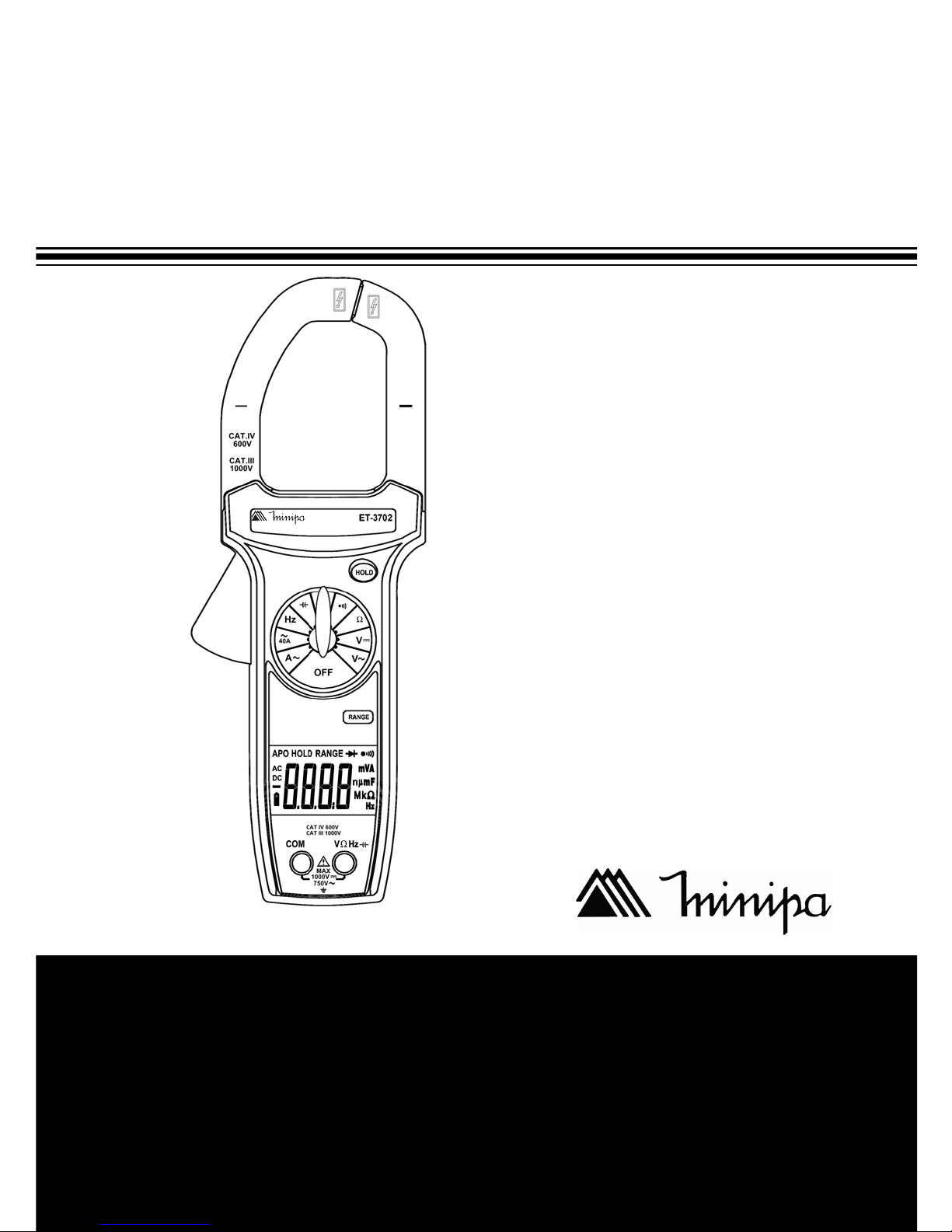
DIGITAL CLAMP METER
INSTRUCTIONS MANUAL
Manual de Instrucciones
Manual de Instruções
*Only illustrative image./Imagen meramente ilustrativa./Imagem meramente ilustrativa.
Pinza Amperimétrica Digital
Alicate Amperímetro Digital
ET-3702

1
CONTENTS
1) INTRODUCTION .............................................................................. 02
2) UNPACKING AND INSPECTION ..................................................... 02
3) SAFETY PRECAUTIONS................................................................... 03
4) SAFETY INFORMA TION .................................................................... 04
A. International Electrical Symbols .................................................. 05
5) PRODUCT DESCRIPTION .............................................................. 05
6) DISPLA Y SYMBOLS ......................................................................... 07
7) OPERATION...................................................................................... 08
A. AC Current Measurement ............................................................ 08
B. DC Voltage Measurement ............................................................ 09
C. AC Voltage Measurement ............................................................ 10
D. Resistance Measurement (Ω) ....................................................... 1 1
E. Continuity Test ( ) ...................................................................... 12
F. Diode Test ( ) ............................................................................. 13
G. Capacitance Measurement (F)..................................................... 14
H. Frequency Measurement (Hz) ..................................................... 15
I. Special Functions......................................................................... 16
8) SPECIFICATIONS............................................................................. 17
A. General Specifications ................................................................. 17
B. Electrical Specifications ............................................................... 18
9) MAINTENANCE ................................................................................. 21
A. Battery Replacement ................................................................... 21
10) WARRANTY ..................................................................................... 22

2
1) INTRODUCTION:
This manual contains information and warnings which must be followed to
ensure safe operation and retain the meter in safe condition.
WARNING
READ “SAFETY INFORMATION” BEFORE USING THE METER.
Portable clamp meter with 4000 counts LCD that is designed for use in the
laboratory , field service, at home, or any circumstance where high current
measurement is required. The clamp meter is built with a design of finger
guard which ensures users operating the instrument under a safety situation; a rugged case that is shock resistant and fire retardant; and electronic overload protection for all functions and ranges. In addition, a
carrying case is available for easy portability of the meter and avoiding
damage.
2) UNPACKING AND INSPECTION:
Open the packing and take out the meter, check the following items:
metI noitpircseD ytitnauQ
1 launaMnoitcurtsnI eceiP1
2 daeLtseT riaP1
3 yrettaBV9 eceiP1
4 esaCtropsnarT eceiP1
If any of the above items are missing or are received in a damaged
condition, please contact the distributor from whom you purchased the
unit.

3
3) SAFETY PRECAUTIONS:
The following safety precautions must be observed to ensure maximum
personal safety during the operation, service and repair of this meter:
1. Read these operating instructions thoroughly and completely before
operating your meter. Pay particular attention to WARNINGS which
will inform you of potentially dangerous procedures. The instructions in
these warnings must be followed.
2. Always inspect your meter, test leads and accessories for any sign of
damage or abnormality before every use. If any abnormal conditions
exist (e.g. broken test leads, cracked cases, display not reading, etc.),
do not attempt to take any measurements.
3. Do not expose the instrument to direct sun light, extreme temperature
or moisture.
4. Never ground yourself when taking electrical measurements. Do not
touch exposed metal pipes, outlets, fixtures, etc., which might be at
ground potential. Keep your body isolated from ground by using dry
clothing, rubber shoes, rubber mats, or any approved insulating material.
5. To avoid electric shock use CAUTION when working with voltages
above 40V DC or 20V AC. Such voltages pose a shock hazard.
6. Never exceed the maximum allowable input value of any function
when taking a measurement. Refer to the specifications for maximum
inputs.
7. Never touch exposed wiring, connections or any live circuit when
attempting to take measurements.
8. Do not attempt to operate this instrument in an explosive atmosphere
(i.e. in the presence of flammable gases or fumes, vapor or dust).
9. When testing for the presence of voltage, make sure the voltage
function is operating properly by reading a known voltage in that
function before assuming that a zero reading indicates a no-voltage
condition. Always test your meter before and after taking measurements on a known live circuit.

4
10. Calibration and repair of any instrument should only be performed by
qualified and trained service technicians.
11. Do not attempt calibration or service unless trained and another person
capable of rendering first aid and resuscitation is present.
12. Remember: Think Safety, Act Safely.
4) SAFETY INFORMA TION:
The instrument complies with class II, overvoltage CAT IV 600V, CAT III
1000V of the IEC61010-1 (EN61010-1); IEC61010-2-032 (EN61010-2-032)
standards. Pollution degree 2 for Indoor Use. If the equipment is used in
a manner not specified, the protection provided by the equipment may be
impaired.
EMC: According with EN61326-1: 2006.
BY IEC61010 OVER VOLT AGE CATEGOR Y INST ALLATION
OVERVOL TAGE CA TEGORY II
Equipment of OVERVOL TAGE CA TEGORY II is energy-consuming equipment supplied from the fixed installation.
NOTE: Examples include household, office and laboratory appliances.
OVERVOLTAGE CA TEGOR Y III
Equipment of OVERVOLTAGE CATEGORY III is equipment in fixed inst allation.
NOTE: Examples includes switches in fixed installations and some equipment for industrial use with permanent connection to the fixed installation.
OVERVOLTAGE CA TEGORY IV
Equipment of OVERVOLTAGE CATEGORY IV is for use at origin of the
installation.
NOTE: Examples include electricity meters and primary over-current protection equipment.
5
When servicing, use only specified replacement parts or equivalent.
WARNING: To avoid electric shock disconnect measuring terminals before removing battery cover.
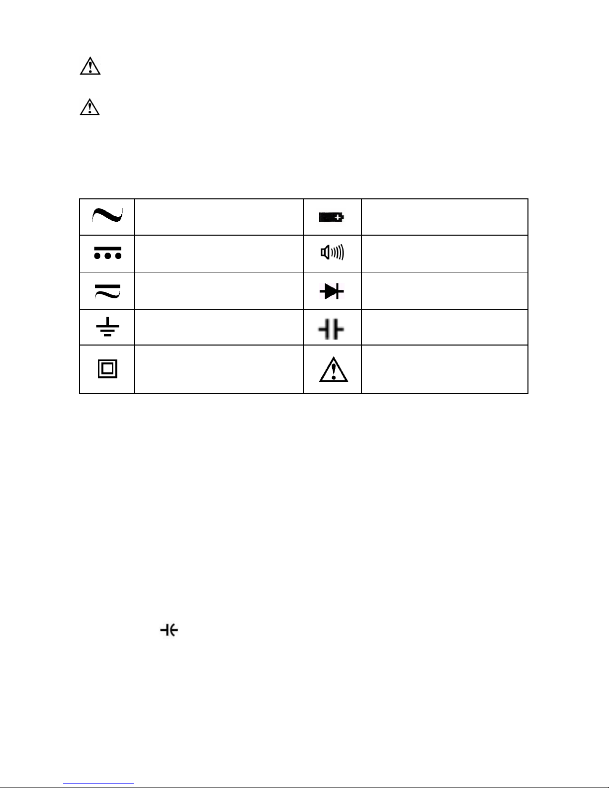
A. International Electrical Symbols
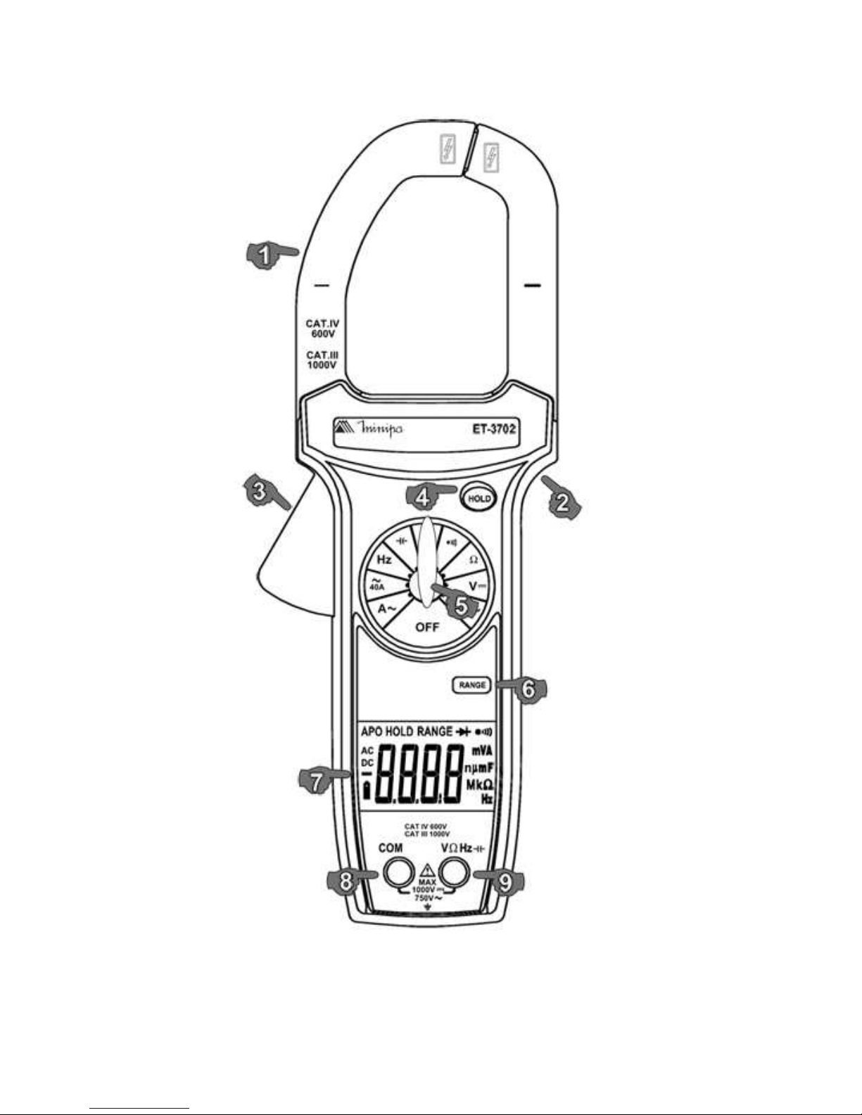
5) PRODUCT DESCRIPTION:
1. Transformer Jaw to pick up the AC Current.
2. Protection Barrier, indicates the limits of safe access during the
measurement.
3. Trigger to open / close the Transformer Jaw.
4. HOLD button.
5. Rotary Switch to select Function / Range.
6. RANGE button.
7. 4000 Counts LCD Display.
8. COM (commom) negative input for all functions (except Current).
9. V Ω Hz positive input for all functions (except Current).
AC (Alternating Current) Low Battery
DC (Direct Current) Continuity Test
AC or DC Diode
Grounding Capacitance Test
Double Insulated Warning. Refer to the
Operating Manual
6
7
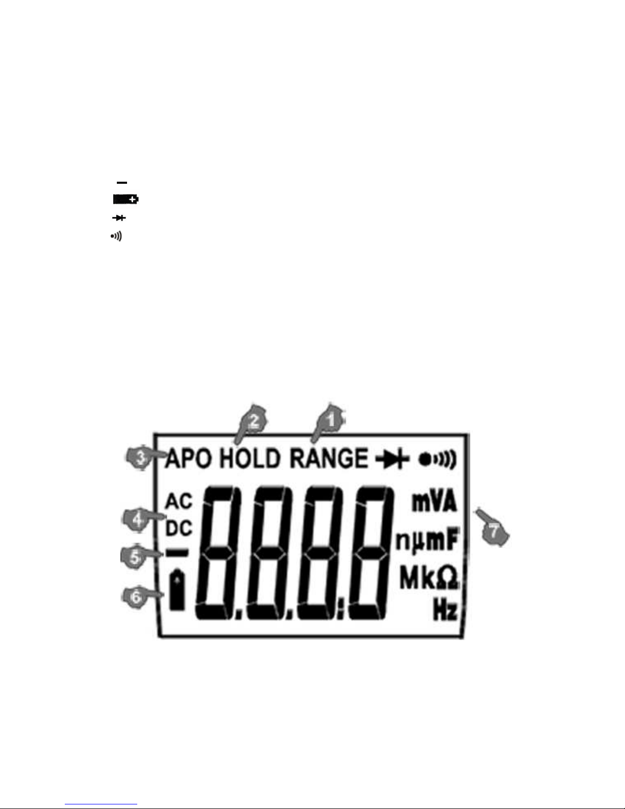
6) DISPLA Y SYMBOLS:
1. RANGE Manual range selection indicator.
2. HOLD Hold Mode Indicator.
3. APO Auto Power Off Indicator (APO).
4. AC AC (Alternating Current/Voltage) Measurement Indicator.
DC DC (Direct Voltage) Measurement Indicator.
5. Negative Polarity Indicator.
6. Low Battery Indicator.
7.7.
7.7.
7. Diode Test Indicator.
Continuity Test Indicator.
V Voltage (Volt) Measurement Unit.
A Current (Ampere) Measurement Unit.
F Capacitance (F) Measurement Unit.
ΩΩ
ΩΩ
Ω Resistance (Ohm) Measurement Unit.
Hz Frequency (Hz) Measurement Unit.
8
7) OPERATION:
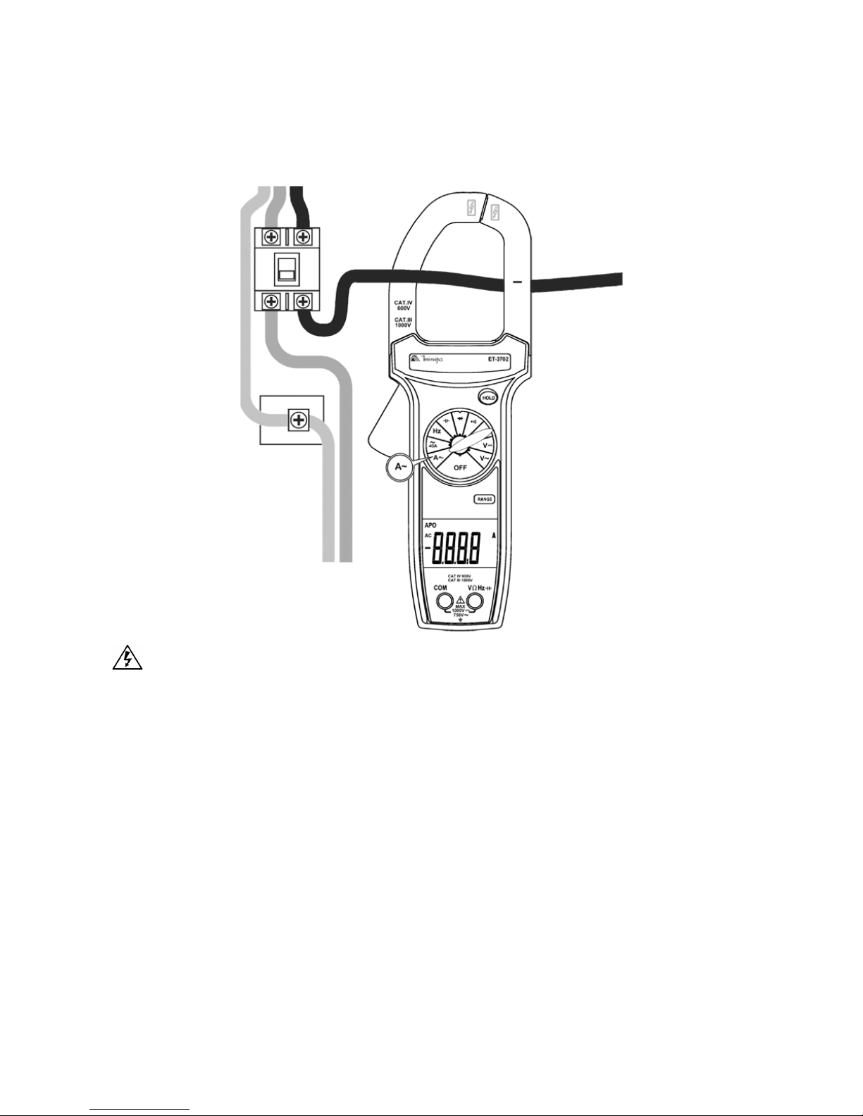
A. AC Current Measurement
CAUTION
T o avoid personal injuries or damages to the meter due an electric
shock, please remove the test leads from the meter and do not
attempt to measure signals higher than 1000A AC.
Set the rotary switch to A~ or 40A~. In the A~ range, use the RANGE key
to manual selection between the 400A and 1000A ranges.
NOTE:
• If the current amplitude is unknown, set the higher range and then
reduce the range to get a more satisfactory reading.
• Press the Trigger to open the Transformer Jaw and clamp only the
conductor with the Current to be measured.
• Wait until display stabilization to take the reading.
• For best accuracy keep the conductor across center of the jaw.
9
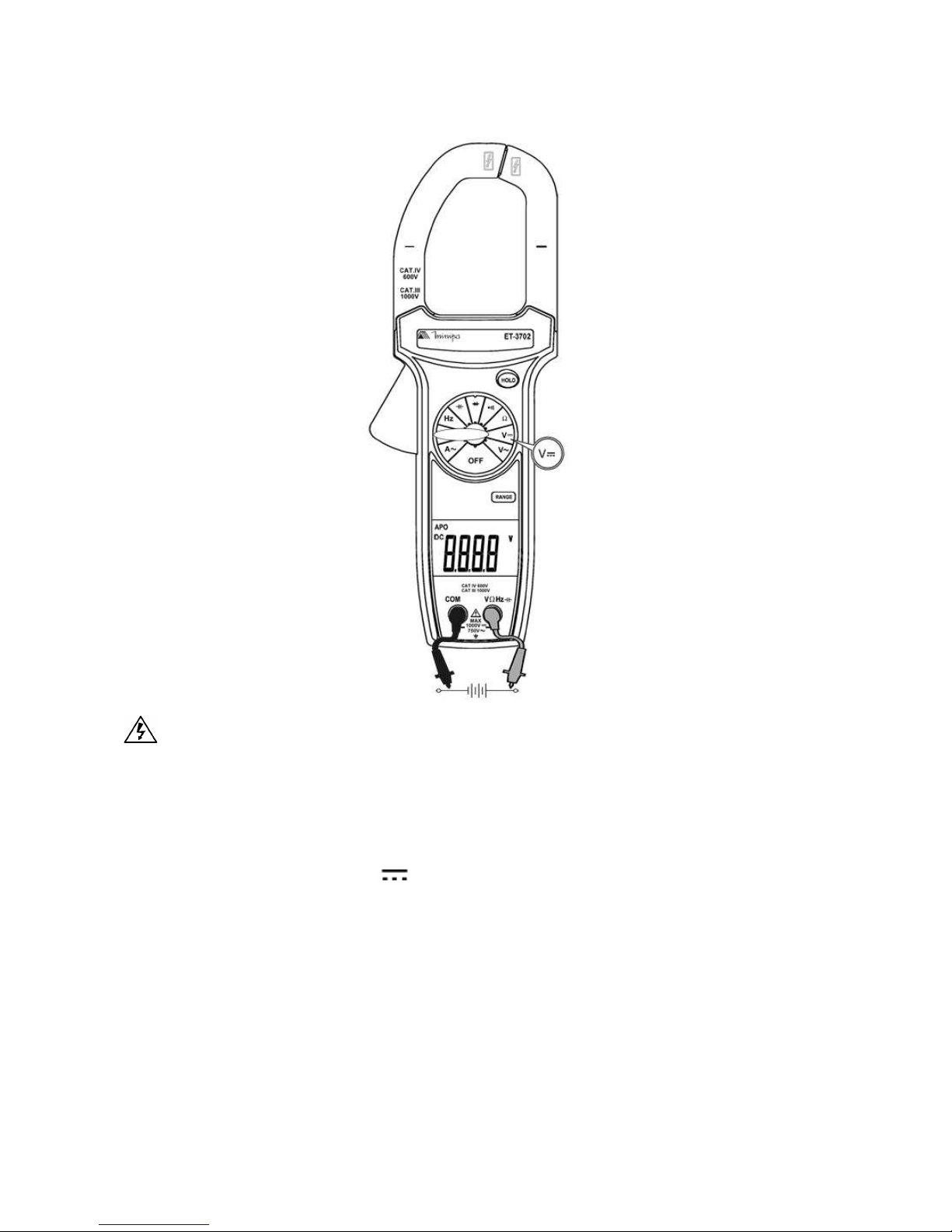
B. DC Voltage Measurement
CAUTION
T o avoid personal injuries or damages to the meter due an electric
shock, please do not attempt to measure voltages higher than
1000V DC/750V AC.
Set the rotary switch to V . Use the RANGE key to manual selection
between the 400mV, 4V, 40V, 400V and 1000V ranges.
NOTE:
• If possible, for safety purpose, turn off the power and discharge all
capacitors of the circuit under test before connecting the test leads to
the points to be measured.
10
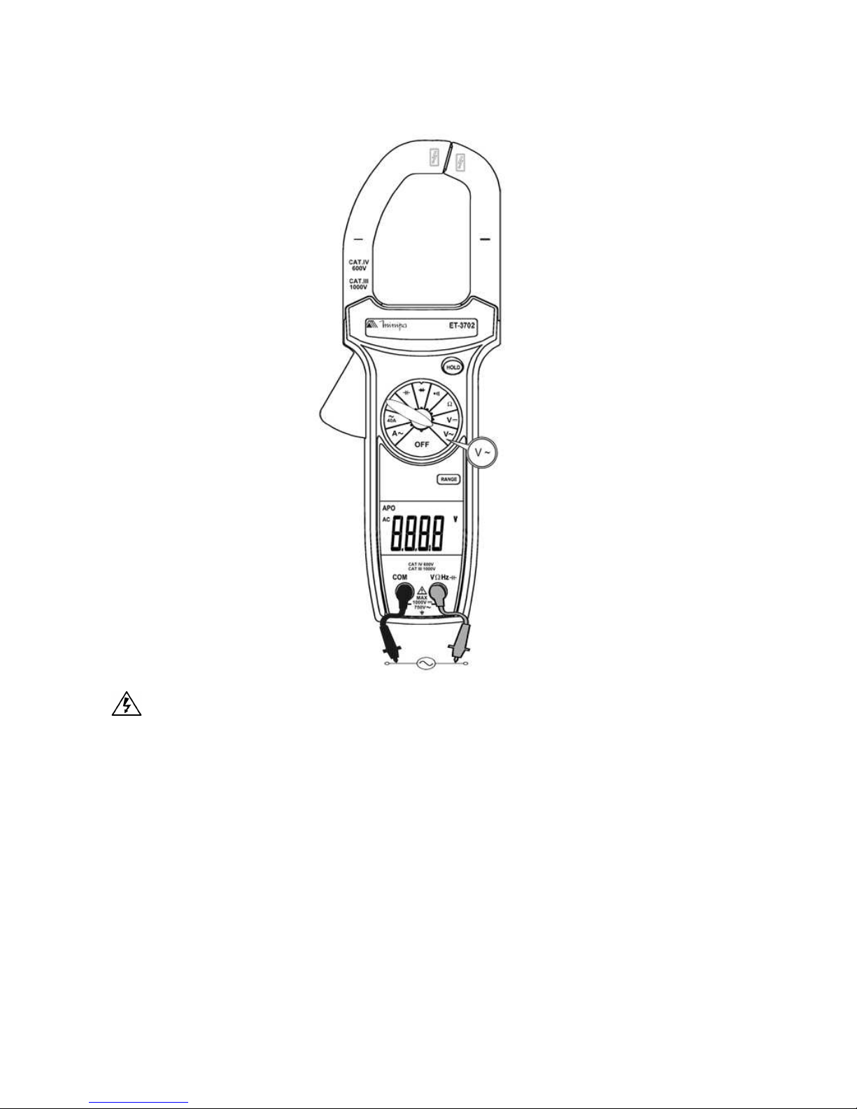
C. AC Voltage Measurement
CAUTION
T o avoid personal injuries or damages to the meter due an electric
shock, please do not attempt to measure voltages higher than
1000V DC/750V AC.
Set the rotary switch to V ~. Use the RANGE key to manual selection
between the 400mV, 4V, 40V, 400V and 750V ranges.
NOTE:
• If possible, for safety purpose, turn off the power and discharge all
capacitors of the circuit under test before connecting the test leads to
the points to be measured.
1 1
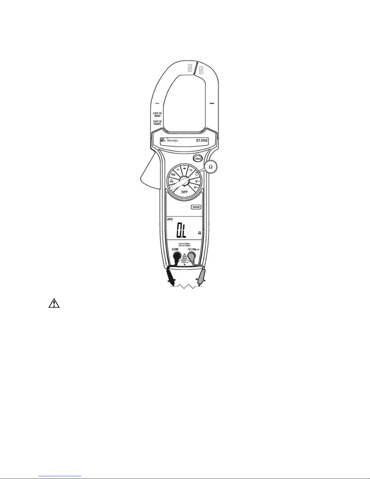
D. Resistance Measurement (
ΩΩ
ΩΩ
Ω)
CAUTION
T o avoid damages to the meter or to the devices under test, disconnect the circuit power and discharge all high voltage capacitors
before taking resistance measurement.
Set the rotary switch to
ΩΩ
ΩΩ
Ω. Use the RANGE key to manual selection
between the 400Ω, 4kΩ, 40kΩ, 400kΩ, 4MΩ and 40MΩ ranges.
NOTE:
• Make sure there is no Voltage in the circuit or device under test.
• The display will show OL when the circuit or device under test is
opened, or when the resistance value is higher than selected range.

12
E. Continuity Test ( )
CAUTION
T o avoid damages to the meter or to the devices under test, disconnect the circuit power and discharge all high voltage capacitors
before taking continuity measurement.
Set the rotary switch to .
NOTE:
• The buzzer will sound if the resistance of the circuit or device under test
is less than 25Ω.
• The display will show OL to indicate that the circuit or device under test
is opened (or > 400Ω ).
13
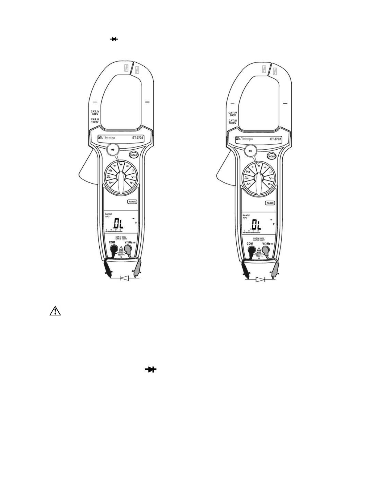
F. Diode Test ( )
Forward Bias Reverse Bias
CAUTION
T o avoid damages to the meter or to the devices under test, disconnect the circuit power and discharge all high voltage capacitors
before taking diode test.
Set the rotary switch to .
NOTE:
• Make sure there is no Voltage in the circuit or device under test.
• When testing a commom silicon diode in good conditions, the voltage drop with
direct bias must be between 0.5V and 0.8V approximately , while with reverse
bias, the indication must be the overrange (OL).

14
G. Capacitance Measurement ( )
CAUTION
T o avoid damages to the meter or to the devices under test, disconnect the circuit power and discharge all high voltage capacitors
before taking capacitance measurement.
Set the rotary switch to . Use the RANGE key to manual selection
between 4µF, 40µF, 400µF and 4mF ranges.
NOTE:
• Observe the correct polarity for polarized capacitors.
• The meter can delay to measure high values capacitors.
• If the display shows “dS.C”, discharge the capacitor before testing.
15
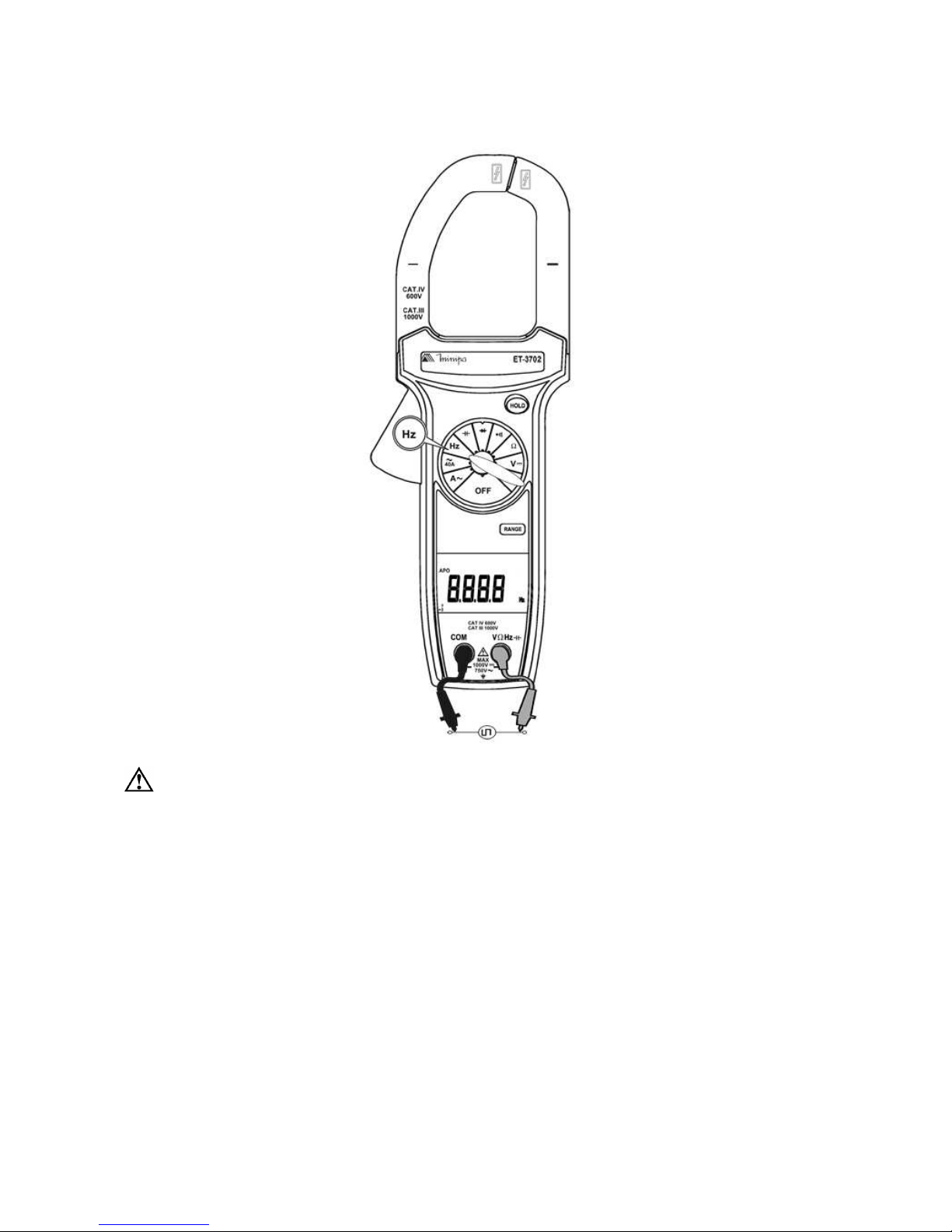
H. Frequency Measurement (Hz)
CAUTION
T o avoid personal injuries or damages to the meter due an electric
shock, please do not attempt to measure voltages higher than
600V RMS.
Set the rotary switch to Hz. Use the RANGE key to manual selection
between the 4kHz, 40kHz, 400kHz and 1MHz ranges.
NOTE:
• To get st able measurements, observe the function Electrical Specifica-
tions carefully.

16
I. Special Functions
Auto Power Off
The auto power off function turn off the meter in the case of inactivity
(approximately after 10 minutes). Initially the meter makes able the auto
power off function automatically. Note that when the auto power off is
active, the APO (auto power off) message will be shown in the display. To
disable the function:
1. Press (and keep holding) the RANGE button when turning on the meter.
Note that when the auto power off function is disabled, the APO message will not be shown in the display.
HOLD Mode
The Hold function freezes the last reading in the display. To use the
function:
1. Press the HOLD button once to enter in the Hold mode.
2. Press the button again to return to normal state of measurement.
RANGE Button
Initially the meter is configured to automatic range selection, but the
manual range selection can be used with RANGE button. To manual range
selection:
1. Press the RANGE button once to disable the automatic selection and
hold manually the meter in the actual range.
2. After activating the manual range selection, press the RANGE button
several times to select the proper range.
3. Press the RANGE button for more than 2 seconds to disable the manual
selection and to return to automatic range selection.

17
8) SPECIFICA TIONS:
A. General Specifications
• Display: 3 3/4 digits, LCD with 4000 counts.
• Polarity Indication: Automatic, negative polarity indication ( - ).
• Overange Indication: (OL) or (-OL) is displayed.
• Low Battery Indication: The symbol is displayed when the bat-
tery voltage drops below accurate operating level.
• Measurement Rate: 2 per second, nominal.
• Operating Environment: 0°C to 50°C with Relative Humidity < 70%.
• Storage Environment: -20°C to 60°C with Relative Humidity
< 80% and without battery.
• Temperature Coefficient: 0.1 x (specified accuracy) / °C (<18°C or
>28°C).
• Auto Power Off: After 10 minutes of inactivity.
• Altitude: 2000m.
• Power: Standard 9V battery, NEDA 1604, IEC 6F22, JIS 006P or
equivalent.
• Battery Life: 150 hours typical with alkaline battery.
• Jaw Opening Capability: 51mm conductor, 70x18mm bus bar.
• Safety: IEC61010-1 Overvoltage Category IV 600V.
• Pollution Degree: 2.
• Dimensions (H x W x D): 279 x 103 x 53 mm.
• Weight: Approx. 510g (including battery).
18
B. Electrical Specifications
The accuracy is given as ± ([% of reading]+[number of digits]) from 18°C
to 28°C, with relative humidity up to 70%.
Specification valid from 10% to 100% of measuring range.
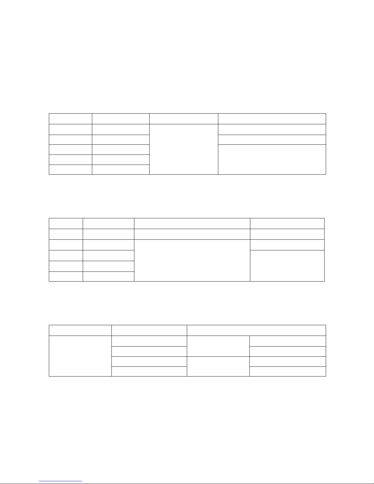
DC Voltage
egnaR noituloseR ycaruccA adartnEedaicnâdepmI
Vm004 Vm1.0
%5.0(±
aeR
2+.d
D
)
M001> Ω
V4 Vm1 M01 Ω
V04 Vm01
M1.9 ΩV004 Vm001
V0001 V1
• Overload Protection: 1000V DC or 750V AC RMS.
AC Volt age
egnaR noituloseR ycaruccA ecnadepmItupnI
Vm004 Vm1.0
%5.1(±
daeR
+.
5
zH001~zH05)d
M001> Ω
V4 Vm1
)d5+.daeR%5.1(±
zH005~zH05
M01 Ω
V04 Vm01
M1.9 Ω
V004 Vm001
V057 V1
• Overload Protection: 1000V DC or 750V AC RMS.
AC Current
egnaR ycneuqerF ycaruccA
A04
A004
A0001
zH06~zH05
A006~0
)D6+.daeR%0.2(±
zH004~zH16 )D6+.daeR%0.3(±
zH06~zH05
A0001~A006
)D6+.daeR%5.2(±
zH004~zH16 D61+.daeR%5.3(±
• Resolution: 0.01A (40A), 0.1A (400A) and 1A (1000A).
• Overload Protection: 1000A AC.
19
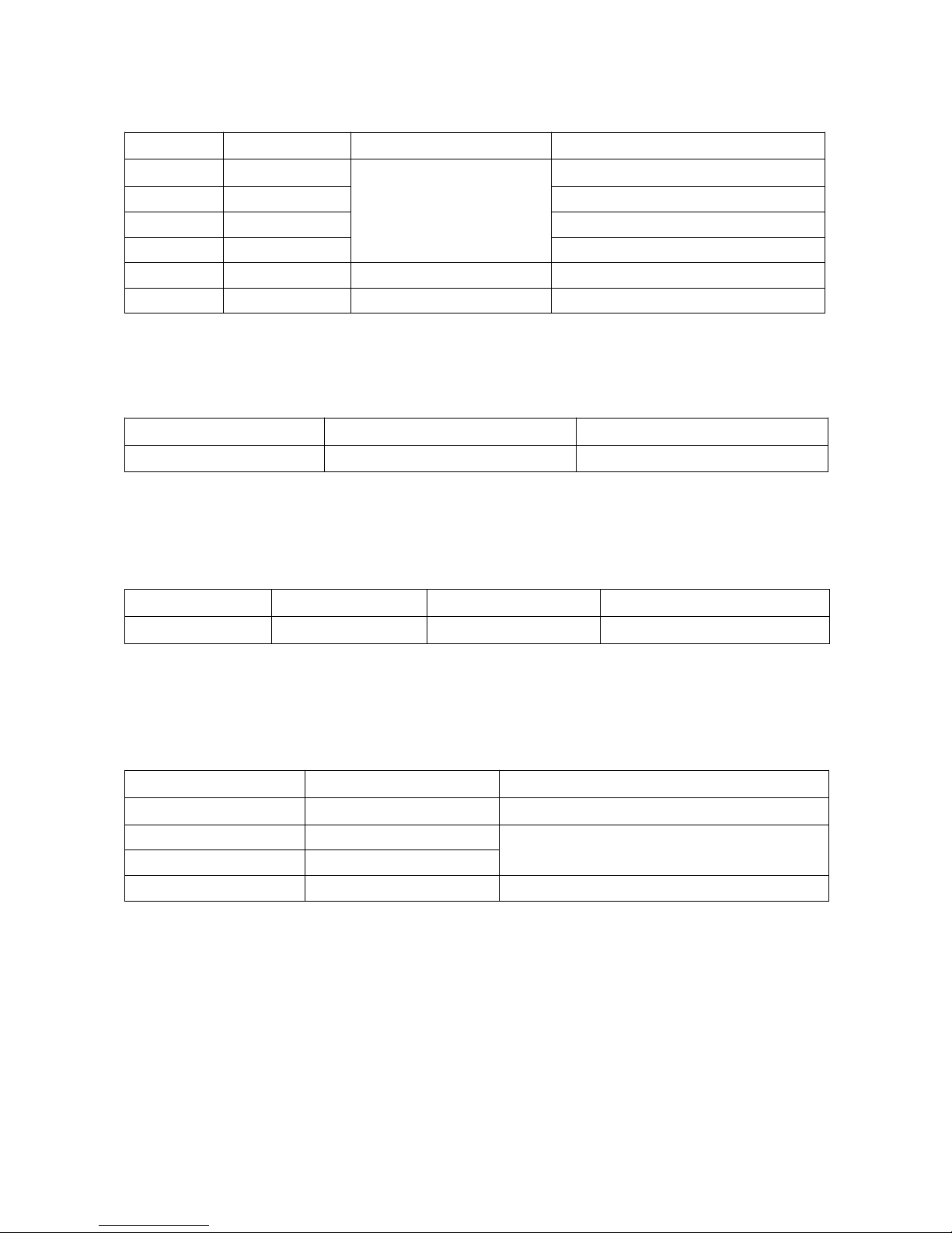
Resistance
egnaR noituloseR ycaruccA egatloVtiucriCnepO
004 Ω m001 Ω
)D5+daeR%0.1(±
cdV2.1-
K4 Ω 1Ω cdV54.0-
K04 Ω 01 Ω cdV54.0-
K004 Ω 001 Ω cdV54.0-
M4 Ω k1 Ω )D5+.daeR%0.2(± cdV54.0-
M04 Ω k01 Ω )D5+.daeR%5.3(± cdV54.0-
• Overload Protection: 600V DC or AC RMS.
Continuity Test
egnaR dlohserhT emiTesnopseR
004 Ω 52euqroneM Ω sm005.xorpA
• Open Circuit Voltage: -1.2V DC.
• Overload Protection: 600V DC or AC RMS.
Diode T est
noituloseR ycaruccA tnerruCtseT egatloVtiucriCnepO
Vm01 )D5+%5.1(± Am8.0 lacipyTCDV2.3
• Audible Threshold: < 0.25V.
• Overload Protection: 600V DC or AC RMS.
Capacitance
egnaR noituloseR ycaruccA
Fµ4 Fn1 )D51+.daeR%0.3(±
Fµ04 Fn01
)D01+.daeR%0.3(±
Fµ004 Fn001
Fm4 Fµ1 )D01+.daeR%0.5(±
• Overload Protection: 600V DC or AC RMS.

20
Frequency
egnaR noituloseR ycaruccA elcyCytuD htdiWesluP
zHk4 zH1
)D5+.daeR%1.0(±
<dna%03>
%07
1> µs
zHk04 zH01
zHk004 zH001
zHM1 zHk1
• Sensibility: > 3.5V.
• Minimum Input: >10Hz.
• Overload Protection: 600V DC or AC RMS.

21
9) MAINTENANCE:
The maintenance consists of periodic cleaning and battery replacement.
The exterior of the instrument can be cleaned with a dry clean cloth to
remove any oil, grease or grime. Never use liquid solvents or detergents.
The repairs or servicing not covered in this manual should only be performed by qualified personnel.
A. Battery Replacement
WARNING
TO A VOID ELECTRICAL SHOCK, DISCONNECT THE TEST LEADS AND
ANY INPUT SIGNALS BEFORE REPLACING THE BATTERY. REPLACE
ONLY WITH SAME TYPE OF BATTERY.
This meter is powered by a NEDA type 1604 or equivalent 9V battery.
When the meter displays the “ ” symbol, the battery must be replaced
to maintain proper operation. Use the following procedure to replacing the
battery:
1. Disconnect test leads from any live source, turn the rotary switch to
OFF, and remove the test leads from the input terminals.
2. The battery cover is secured to the bottom case by a screw. Using a
Phillips-head screwdriver, remove the screw from the battery cover
and remove the battery cover.
3. Remove battery and replace with a new equivalent 9V battery.
4. Replace the battery cover and reinstall the screw.
 Loading...