

Page 1
Contents
A - Z
Online Edition for Part no. 01 41 2 601 475 - © 11/08 BMW AG
OWNER'S MANUAL
MINI E
Page 2

Online Edition for Part no. 01 41 2 601 475 - © 11/08 BMW AG
Page 3

MINI E
Online Edition for Part no. 01 41 2 601 475 - © 11/08 BMW AG
Congratulations on your new MINI
This Owner's Manual should be considered a permanent part of
this vehicle. It should stay with the vehicle when sold to provide
the next owner with important operating, safety and maintenance information.
We wish you an enjoyable driving experience.
Page 4

© 2008 Bayerische Motoren Werke
Online Edition for Part no. 01 41 2 601 475 - © 11/08 BMW AG
Aktiengesellschaft
Munich, Germany
Reprinting, including excerpts, only with the
written consent of BMW AG, Munich.
US English XI/08
Printed on environmentally friendly paper,
bleached without chlorine, suitable for recycling.
Page 5

CONTENTS
Online Edition for Part no. 01 41 2 601 475 - © 11/08 BMW AG
The fastest way to find information on a particular topic or item is by using the index, refer to
page 108.
Using this Owner's Manual
4 Notes
6 Reporting safety defects
AT A GLANCE
10 Cockpit
CONTROLS
18 Opening and closing
25 Adjustments
30 Transporting children safely
32 Driving
39 Everything under control
48 Technology for driving comfort and safety
55 Lamps
59 Climate
62 Practical interior accessories
DRIVING TIPS
66 Things to remember when driving
MOBILITY
72 Charging the high voltage battery
76 Wheels and tires
82 Under the bonnet
84 Maintenance
85 Care
89 Replacing components
94 Giving and receiving assistance
96 Indicator and warning lamps
REFERENCE
106 Technical data
108 From A to Z
REFERENCE AT A GLANCECONTROLSDRIVING TIPSMOBILITY
3
Page 6
Notes
Online Edition for Part no. 01 41 2 601 475 - © 11/08 BMW AG
The electric motor of
Notes
your MINI
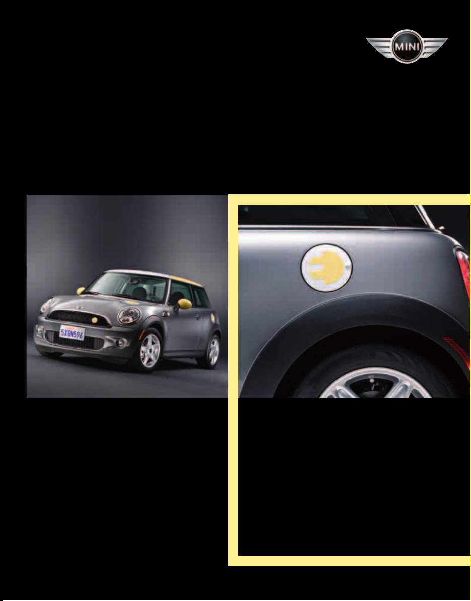
Your MINI is an electric vehicle that produces no
emissions, even while it is being operated. It is
powered entirely by an environmentally friendly
electric motor.
The energy for operating the electric motor is
supplied by the high voltage battery in the cargo
bay. It can be charged by connecting it to a stationary power supply and by converting kinetic
energy.
Using this Owner's Manual
We have tried to make all the information in this
Owner's Manual easy to find. The fastest way to
find specific topics is to refer to the detailed
index at the back of the manual. If you wish to
gain an initial overview of your vehicle, you will
find this in the first chapter.
Additional sources of information
Should you have any other questions, your MINI
Dealer will be glad to advise you at any time.
You can find more information about the MINI,
for example on its technology, on the Internet at
www.MINI.com.
Symbols used
Indicates precautions that must be followed precisely in order to avoid the pos-
sibility of personal injury and serious damage to
the vehicle.<
Indicates information that will assist you in
gaining the optimum benefit from your
vehicle and enable you to care more effectively
for your vehicle.<
Refers to measures that can be taken to
help protect the environment.<
< Marks the end of a specific item of informa-
tion.
*
Indicates special equipment, country-specific
equipment and optional accessories, as well as
equipment and functions not yet available at the
time of printing.
Symbols on vehicle components
Indicates that you should consult the relevant section of this Owner's Manual for
information on a particular part or assembly.
Indicates that there is a risk of sus-
taining life threatening injury from
electric shock when the high voltage equipment
is used improperly.
Your vehicle
The manufacturer of your MINI is the Bayerische
Motoren Werke Aktiengesellschaft, BMW AG.
If your MINI features eq uipment not described in
this Owner's Manual, observe the enclosed Supplementary Owner's Manuals.
Editorial notice
The manufacturer pursues a policy of continuous, ongoing development that is conceived to
ensure that MINI vehicles continue to embody
the highest quality and safety standards combined with advanced, state-of-the-art technology. For this reason, it is possible in exceptional
cases that features described in this Owner's
Manual could differ from those on your vehicle.
For your safety
Your MINI is powered by a high voltage electrical
system. When repair work is not performed
4
Page 7

properly, there is the risk of sustaining a life
Online Edition for Part no. 01 41 2 601 475 - © 11/08 BMW AG
threatening electric shock.
Have the vehicle repaired by specially
trained technicians only. Otherwise there
is the risk of fatal injury from high voltage when
work is performed improperly.<
Maintenance and repair
Advanced technology, e.g. the use of
modern materials and powerful electronics, requires specially adapted maintenance and
repair methods. Therefore, have the necessary
work on your MINI only carried out by a MINI
Dealer or a workshop that has specially trained
personnel working in accordance with the specifications of the MINI manufacturer. Otherwise
there is the risk of fatal injury from high voltage
when work is performed improperly. Consequential damage and the associated safety risks
are also possible.<
Malfunction
In the event of a malfunction in your MINI,
please call the Service Hotline.
Please find the telephone number in your leasing papers.
Parts and accessories
For your own safety, use genuine parts
and accessories approved by the manufacturer of the MINI.
When you purchase accessories tested
and approved by the manufacturer of the MINI
and Original MINI Parts, you simultaneously
acquire the assurance that they have been thoroughly tested by the manufacturer of the MINI
to ensure optimum performance when installed
on your vehicle.
The manufacturer of the MINI warrants these
parts to be free from defects in material and
workmanship.
The manufacturer of the MINI will not accept any
liability for damage resulting from installation of
parts and accessories not approved by the manufacturer of the MINI.
The manufacturer of the MINI cannot test every
product made by other manufacturers to verify
if it can be us ed on a MINI safel y and w ithou t ris k
to either the vehicle, its operation, or its occupants.
Original MINI Parts, MINI Accessories and other
products approved by the manufacturer of the
MINI, together with professional advice on using
these items, are available from all MINI Dealers.
Installation and operation of non-MINI
approved accessories such as alarms, radios,
amplifiers, radar detectors, wheels, suspension
components, brake dust shields, telephones,
including operation of any mobile phone from
within the vehicle without using an externally
mounted antenna, or transceiver eq uipment, for
instance, CBs, walkie-talkies, ham radios or similar accessories, may cause extensive damage to
the vehicle, compromise its safety, interfere with
the vehicle's electrical system or affect the validity of the MINI Limited Warranty. See your MINI
Dealer for additional information.<
Maintenance, replacement, or repair of
the emission control devices and systems
may be performed by any automotive repair
establishment or individual using any certified
automotive part.<
California Proposition 65 warning
California law requires us to issue the following
warning:
Engine exhaust and a wide variety of
automobile components and parts,
including components found in the interior furnishings in a vehicle, contain or emit chemicals
known to the State of California to cause cancer
and birth defects and reproductive harm. In
addition, certain fluids contained in vehicles and
certain products of component wear contain or
emit chemicals known to the State of California
to cause cancer and birth defects or other reproductive harm.
Battery posts, terminals and related accessories
contain lead and lead compounds. Wash your
hands after handling.
Used engine oil contains chemicals that have
caused cancer in laboratory animals. Always
protect your skin by washing thoroughly with
soap and water.<
REFERENCE AT A GLANCECONTROLSDRIVING TIPSMOBILITY
5
Page 8

Service and warranty
Online Edition for Part no. 01 41 2 601 475 - © 11/08 BMW AG
We recommend that you read this publication
thoroughly.
Your MINI is covered by the following warran-
Notes
ties:
> New Vehicle Limited Warranty
> Rust Perforation Limited Warranty
> Federal Emissions System Defect Warranty
> Federal Emissions Performance Warranty
> California Emission Control System Limited
Warranty
Detailed information about these warranties is
listed in the Service and Warranty Information
Booklet for US models.
Reporting safety defects
For US customers
The following applies only to vehicles owned
and operated in the US.
If you believe that your vehicle has a defect
which could cause a crash or could cause injury
or death, you should immediately inform the
National Highway Traffic Safety Administration,
NHTSA, in addition to notifying MINI of North
America, LLC, P.O. Box 1227, Westwood, New
Jersey 07675-1227, Telephone 1-800-831-
1117.
If NHTSA receives similar complaints, it may
open an investigation, and if it finds that a safety
defect exists in a group of vehicles, it may order
a recall and remedy campaign. However, NHTSA
cannot become involved in individual problems
between you, your dealer, or MINI of North
America, LLC.
To contact NHTSA, you may call the Vehicle
Safety Hotline toll-free at 1-888-327-4236
(TTY: 1-800-424-9153);
go to http://www.safercar.gov; or write to:
Administrator, NHTSA, 400 Seventh Street, SW.,
Washington, DC 20590. You can also obtain
other information about motor vehicle safety
from http://www.safercar.gov
6
Page 9

REFERENCE AT A GLANCECONTROLSDRIVING TIPSMOBILITY
Online Edition for Part no. 01 41 2 601 475 - © 11/08 BMW AG
7
Page 10
Online Edition for Part no. 01 41 2 601 475 - © 11/08 BMW AG
Page 11

AT A GLANCE
Online Edition for Part no. 01 41 2 601 475 - © 11/08 BMW AG
AT A GLANCE
CONTROLS
DRIVING TIPS
MOBILITY
REFERENCE
Page 12
Cockpit
Online Edition for Part no. 01 41 2 601 475 - © 11/08 BMW AG
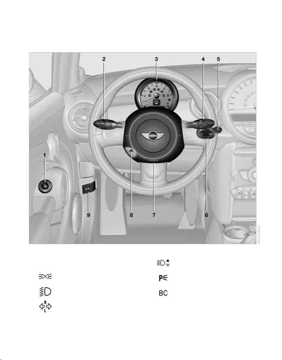
Around the steering wheel: Controls and displays
Cockpit
1 Adjusting the exterior mirrors, folding them
in and out 28
2
10
Parking lamps 55
Low beams 55
Turn signals 36
High beams 57
Headlamp flasher 36
Standing lamps 57
Onboard computer 40
Page 13

3 Charge status display 12
Online Edition for Part no. 01 41 2 601 475 - © 11/08 BMW AG
Instrument lighting 57
Resetting the trip odometer 39
4
5
Wiper system 37
Switching the ignition and run position on/off 32
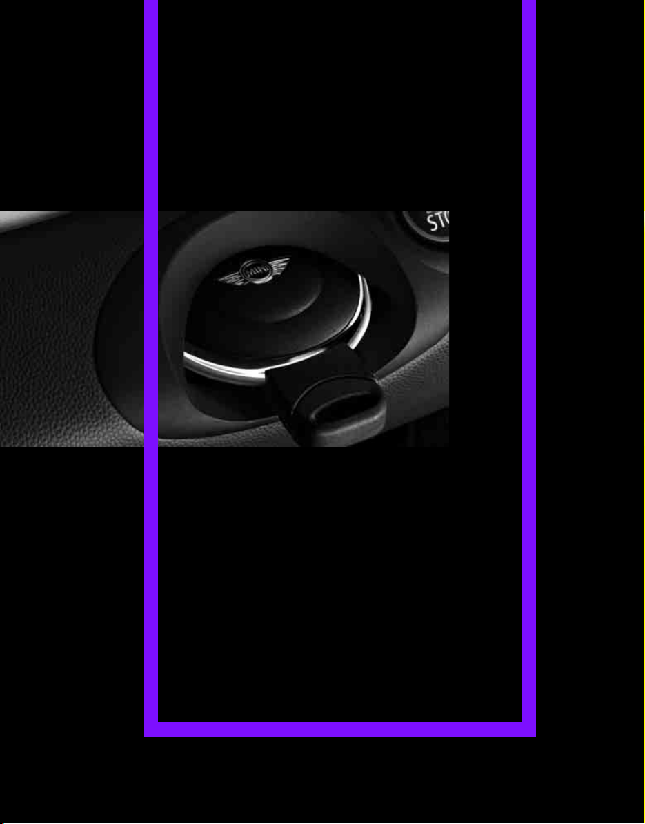
6 Ignition lock 32
7 Horn: the entire surface
8 Adjusting the steering wheel 29
9 Releasing the bonnet 82
REFERENCE AT A GLANCECONTROLSDRIVING TIPSMOBILITY
11
Page 14
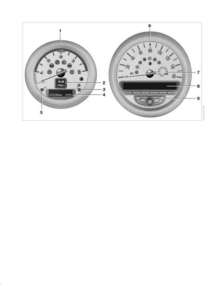
Displays
Online Edition for Part no. 01 41 2 601 475 - © 11/08 BMW AG
Cockpit
1 Charge status display 39
with indicator and warning lamps 13
2 Display for
> Clock 39
> Outside temperature 39
> Current vehicle speed 39
> Indicator and warning lamps 13
3 Resetting the trip odometer 39
4 Display for
> Selector lever position 33
> Onboard computer 40
> Date of next scheduled service, and
remaining distance to be driven 43
> Odometer and trip odometer 39
> Resetting the Tire Pressure Monitor 49
> Settings and information 41
> Personal Profile settings 18
5 Instrument lighting 57
6 Speedometer
with indicator and warning lamps 13
7 Energy consumption indicator 40
8 Radio display, refer to separate Owner's
Manual
9 Radio, refer to separate Owner's Manual
12
Page 15
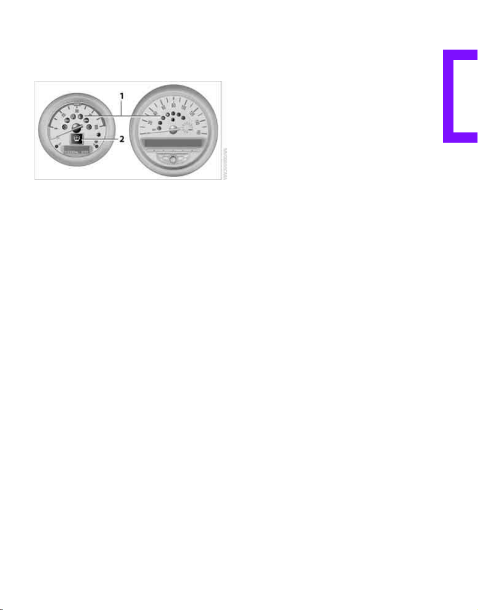
Indicator and warning
Online Edition for Part no. 01 41 2 601 475 - © 11/08 BMW AG
lamps
The concept
Indicator and warning lamps can light up in various combinations and colors in indicator area 1
or 2.
Some lamps are checked for proper functioning
and thus come on briefly when the run position
or the ignition is switched on.
What to do in case of a malfunction
A list of all indicator and warning lamps, as well
as notes on possible causes of malfunctions and
on how to respond, can be found starting on
page 96.
REFERENCE AT A GLANCECONTROLSDRIVING TIPSMOBILITY
13
Page 16
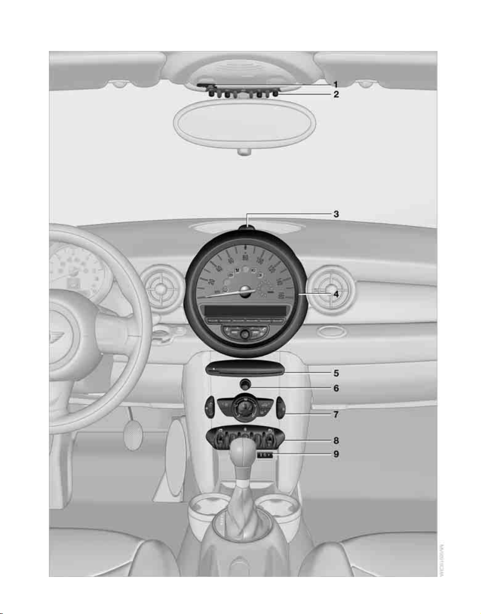
Around the center console
Online Edition for Part no. 01 41 2 601 475 - © 11/08 BMW AG
Cockpit
14
Page 17
1 Indicator warning lamp for front passenger
Online Edition for Part no. 01 41 2 601 475 - © 11/08 BMW AG
airbags 53
2
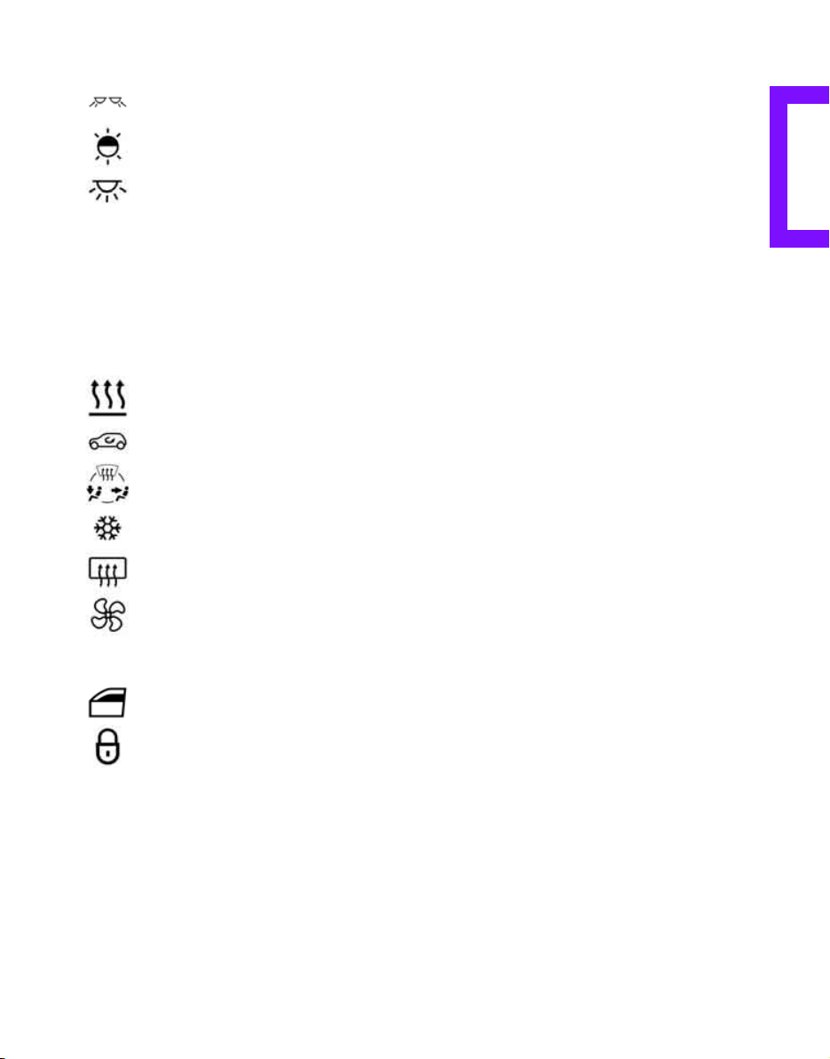
Reading lamps 58
Color of ambient lighting 58
Interior lamps 57
3 Hazard warning flashers
4 Speedometer 12
5 Drive for audio CDs
6 Switching audio sources on/off and adjust-
ing volume
7 Air conditioning system
Temperature 60
Recirculated air mode 60
Air distribution for air
conditioner 60
Cooling function 60
Rear window defroster 60
Air flow rate 60
8 Switches in center console
Power windows 23
Central locking system, inside 22
9 AUX-In port 62
REFERENCE AT A GLANCECONTROLSDRIVING TIPSMOBILITY
15
Page 18
Online Edition for Part no. 01 41 2 601 475 - © 11/08 BMW AG
Page 19

AT A GLANCE
Online Edition for Part no. 01 41 2 601 475 - © 11/08 BMW AG
CONTROLS
CONTROLS
DRIVING TIPS
MOBILITY
REFERENCE
Page 20
Opening and closing
Online Edition for Part no. 01 41 2 601 475 - © 11/08 BMW AG
Only park the vehicle with the doors and
windows fully closed to prevent water
from entering into the vehicle, e. g. if it should
rain. Otherwise there is a risk of personal injury
and damage to the vehicle electronics.<
If you notice water in the vehicle when
you open the vehicle, do not enter the
vehicle and contact your MINI Dealer. Otherwise
there is a risk of personal injury due to the high
voltage.<
Keys/remote controls
Opening and closing
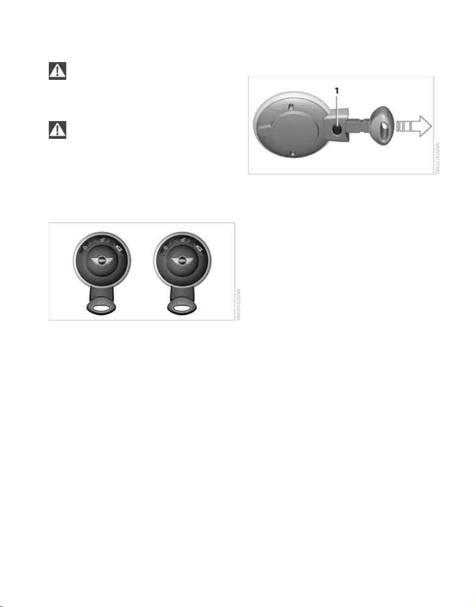
Remote control
Each remote control contains a rechargeable
battery that is recharged when it is in the ignition lock while the car is being driven. You
should therefore use each remote control at
least twice a year to maintain the charge status.
If more than one remote control is used, the settings called up and implemented depend on
which remote control is recognized when the
car is unlocked, refer to Personal Profile,
page 18.
In addition, information about service requirements is stored in the remote control, refer to
Service data in the remote control, page 84.
New remote controls
Your MINI Dealer can supply new remote controls as additional units or as replacements in the
event of loss.
Integrated key
Press button 1 to release the key.
The integrated key fits the following locks:
> Driver's door, page 21.
Personal Profile
The concept
The functions of your MINI can be set individually. By means of Personal Profiles, most of these
settings are stored for the remote control currently in use. When you unlock the car, the
remote control is recognized and the settings
stored for it are called up and implemented.
This means that your settings will be activated
for you, even if in the meantime your car was
used by someone else with another remote control and the corresponding settings.
At most three remote controls can be set for
three different people. A prerequisite is that
each person uses a separate remote control.
Personal Profile settings
For more information on specific settings, refer
to the specified pages.
> Response of the central locking system
when the car is being unlocked 19
> Automatic locking of the vehicle 22
> Triple turn signal activation 36
18
Page 21
> Settings for the displays in the speedometer
Online Edition for Part no. 01 41 2 601 475 - © 11/08 BMW AG
and charge status display:
> 12h/24h mode of the clock, refer to For-
mats and units of measure 42
> Date format, refer to Formats and units
of measure 42
> Units of measure for energy consump-
tion, distance covered/remaining distances and temperature, refer to Formats
and units of measure 42
> Light settings:
> Pathway lighting 55
> Daytime running lamps 56
> Entertainment:
> Audio volume, refer to separate Owner's
Manual
> Speed-dependent volume, refer to sepa-
rate Owner's Manual
Central locking system
Operating from inside
Button for central locking system, page 22.
In the event of a sufficiently severe accident, the
central locking system unlocks automatically. In
addition, the hazard warning flashers and interior lamps come on.
Opening and closing: from outside
Persons or animals in a parked vehicle
could lock the doors from the inside. Take
the key with you when you leave the vehicle so
that the vehicle can be opened from the outside.<
Only park the vehicle with the doors and
windows fully closed to prevent water
from entering into the vehicle, e. g. if it should
rain. Otherwise there is a risk of personal injury
and damage to the vehicle electronics.<
Using the remote control
The concept
The central locking system is ready for operation
whenever the driver's door is closed.
The system simultaneously engages and
releases the locks on the following:
> Doors
> Tailgate
> Charge socket door
Operating from outside
> Via the remote control
> Via the door lock
The anti-theft system is also operated at the
same time. It prevents the doors from being
unlocked using the lock buttons or door handles. The remote control can also be used to
switch on/off the welcome lamps and interior
lamps.
Unlocking
Press the button.
The welcome lamps and interior lamps come on.
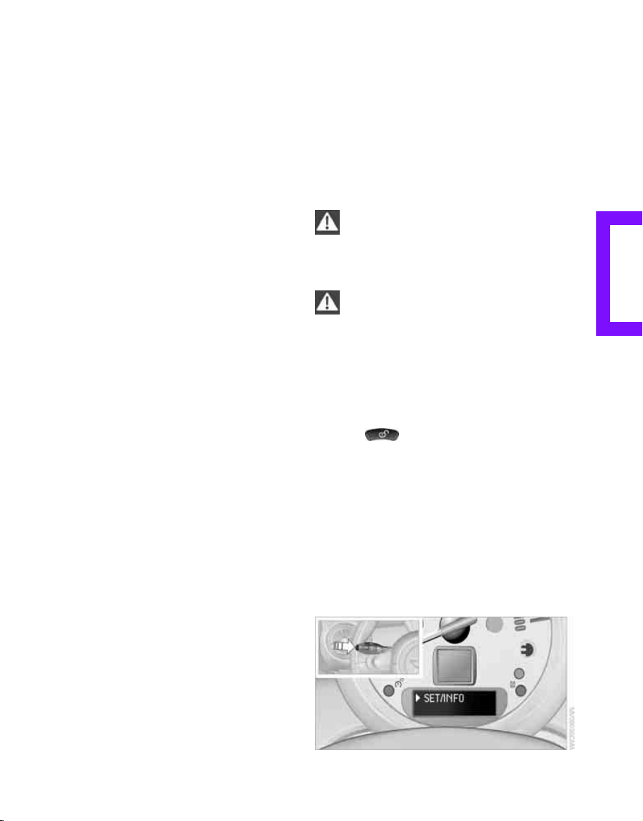
Unlocking mode
You can also set which parts of the car are
unlocked. The setting is stored for the remote
control in use.
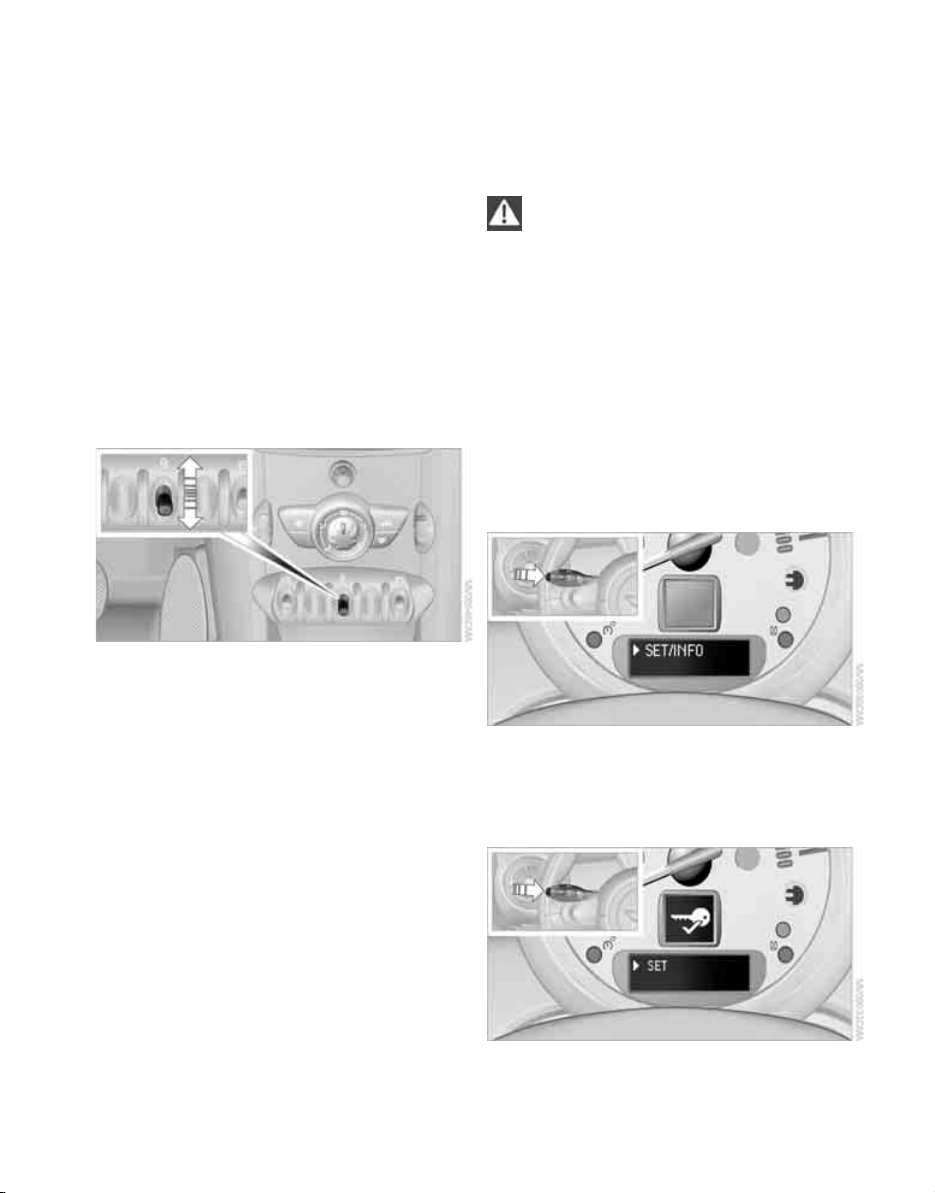
1. Switch on the ignition, refer to page 32.
2. Briefly press the button in the turn indicator
lever repeatedly until "SET/INFO" is displayed.
REFERENCE AT A GLANCECONTROLSDRIVING TIPSMOBILITY
19
Page 22
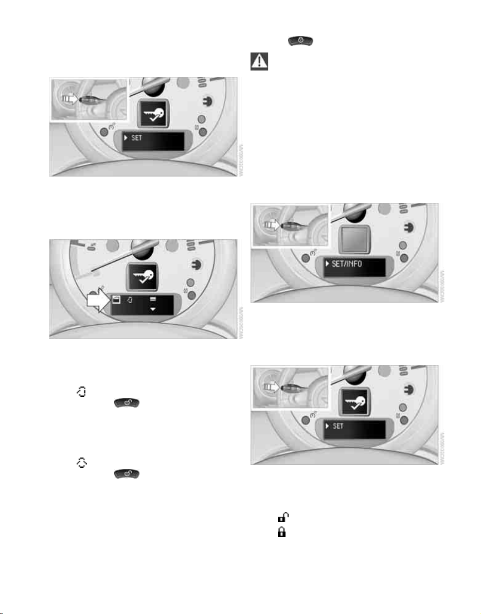
3. Press and hold the button until the display
Online Edition for Part no. 01 41 2 601 475 - © 11/08 BMW AG
changes.
4. Briefly press the button repeatedly until the
symbol and "SET" are displayed.
5. Press and hold the button until the display
changes.
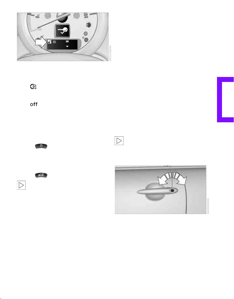
6. Briefly press the button repeatedly until the
display shows the illustrated symbol, arrow.
Opening and closing
7. Press and hold the button until the display
changes.
8. Briefly press the button to select:
>
Press the button once to unlock
only the driver's door and charge socket
door.
Press the button twice to unlock the
entire vehicle.
>
Press the button once to unlock
the entire vehicle.
9. Press and hold the button until the display
changes. The setting is stored for the remote
control currently in use.
Locking
Press the button.
Do not lock the vehicle from the outside if
there is any person inside, because the
vehicle cannot be unlocked from inside without
special knowledge.<
Setting confirmation signals
To have the vehicle confirm when it has been
locked or unlocked.
1. Switch on the ignition, refer to page 32.
2. Briefly press the button in the turn indicator
lever repeatedly until "SET/INFO" is displayed.
3. Press and hold the button until the display
changes.
4. Briefly press the button repeatedly until the
symbol and "SET" are displayed.
5. Press and hold the button until the display
changes.
6. Briefly press the button to select, arrow:
> Confirmation signal during unlocking
> Confirmation signal during locking
20
Page 23
7. Press and hold the button until the display
Online Edition for Part no. 01 41 2 601 475 - © 11/08 BMW AG
changes.
8. Briefly press the button to select:
>
The hazard warning flashers light up
during unlocking/locking.
>
The function is deactivated.
9. Press and hold the button until the display
changes. The setting is stored.
Switching on interior lamps
While the car is locked:
Press the button.
You can also use this function to locate your
vehicle in parking garages, etc.
Unlocking the tailgate
Press the button.
When it is opened, the tailgate swings
upward and outward to the rear. Ensure
that there is sufficient clearance.
To prevent accidentally locking yourself out, do
not place the key down in the cargo bay. If the
tailgate was locked before opening, it will be
locked again after it is closed.
Before and after each trip, check that the tailgate has not been inadvertently unlocked.<
Malfunctions
The remote control may malfunction due to
local radio waves. If this occurs, unlock and lock
the car at the door lock with the integrated key.
If the car can no longer be locked with a remote
control, the battery in the remote control is discharged. Use this remote control during an
extended drive; this will recharge the battery,
page 18.
For US owners only
The transmitter and receiver units comply with
part 15 of the FCC/Federal Communications
Commission regulations. Operation is governed
by the following:
FCC ID:
LX8766S
LX8766E
LX8CAS
Compliance statement:
This device complies with part 15 of the FCC
Rules. Operation is subject to the following two
conditions:
> This device must not cause harmful interfer-
ence, and
> This device must accept any interference
received, including interference that may
cause undesired operation.
Any unauthorized modifications or
changes to these devices could void the
user's authority to operate this equipment.<
Using the door lock
You can set which parts of the car are unlocked,
page 19.
To lock all doors, the charge socket door and the
tailgate together:
With the doors closed, press the interior central
locking button, page 22 to lock the vehicle.
Unlocking and opening the driver or front passenger door, page 22.
REFERENCE AT A GLANCECONTROLSDRIVING TIPSMOBILITY
21
Page 24
Locking the vehicle.
Online Edition for Part no. 01 41 2 601 475 - © 11/08 BMW AG
> Lock the driver's door with the integrated
key via the door lock, or
> press the safety lock button on the front
passenger door and close the door from
the outside.
Manual operation
In the event of an electrical malfunction, the
driver's door can be unlocked or locked by turning the integrated key in the door lock to the end
positions.
Opening and closing: from inside
Opening and closing
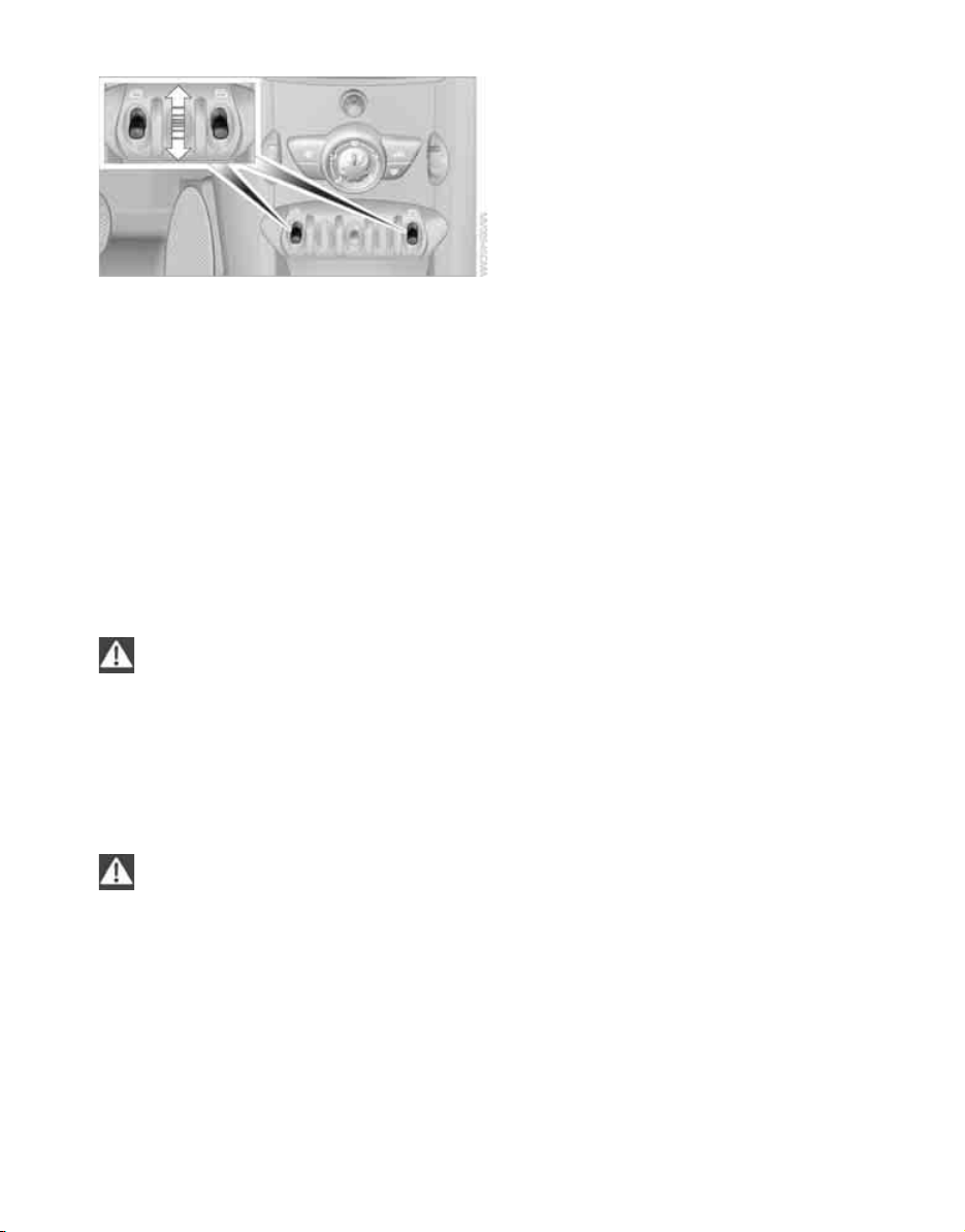
Locking
> Press the switch or
> press down the safety lock button of a door.
To prevent you from being locked out, the
open driver's door cannot be locked using
the lock button.
Persons or animals in a parked vehicle
could lock the doors from the inside. Take
the key with you when you leave the vehicle so
that the vehicle can be opened from the outside.<
Automatic locking
You can also set the situations in which the car
locks. The setting is stored for the remote control in use.
1. Switch on the ignition, refer to page 32.
2. Briefly press the button in the turn indicator
lever repeatedly until "SET/INFO" is displayed.
The switch locks or unlocks the doors and tailgate when the doors are closed, but the antitheft system is not activated. The charge socket
*
door remains unlocked
.
Unlocking and opening
> Either unlock the doors together using the
switch for the central locking system and
then pull the door handle above the armrest
or
> pull on the door handle of either door twice:
the first time unlocks the door, the second
time opens it.
22
3. Press and hold the button until the display
changes.
4. Briefly press the button repeatedly until the
symbol and "SET" are displayed.
5. Press and hold the button until the display
changes.
Page 25
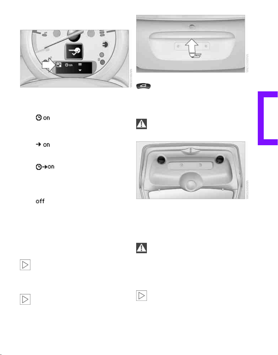
6. Briefly press the button repeatedly until the
Online Edition for Part no. 01 41 2 601 475 - © 11/08 BMW AG
display shows the illustrated symbol, arrow.
7. Press and hold the button until the display
changes.
8. Briefly press the button to select:
>
The central locking system automatically
locks the vehicle after some time if no
door has been opened.
>
The central locking system automatically
locks the vehicle as soon as you drive off.
>
The central locking system automatically
locks the vehicle after some time if no
door has been opened, or as soon as you
drive off.
>
The central locking system remains
unlocked.
9. Press and hold the button until the display
changes. The setting is stored.
Press the button in the handle, arrow, or the
button of the remote control, for an
extended period. The tailgate is unlocked and
can be opened.
Closing
Make sure that the closing path of the tailgate is clear, otherwise injuries may
occur.<
The handle recesses on the interior trim panel of
the tailgate make it easier to pull it down.
Windows
Tailgate
To avoid damage, make sure there is
sufficient clearance before opening the
tailgate.<
To open
In some national-market versions, the tailgate cannot be unlocked using the remote
control unless the vehicle is unlocked first.<
To prevent injuries, exercise care when
closing the windows and keep them in
your field of vision until they are shut.
Take the remote control with you when you
leave the car, otherwise children could operate
the electric windows and possibly injure themselves.<
If, after a window is opened and closed
several times in close succession, the window can only be closed and not opened, the system is overheated. Let the system cool with the
ignition or run position switched on.<
23
REFERENCE AT A GLANCECONTROLSDRIVING TIPSMOBILITY
Page 26
Opening, closing
Online Edition for Part no. 01 41 2 601 475 - © 11/08 BMW AG
> Press the switch downwards.
The window opens until you release the
switch.
> Tap the switch downwards.
The window opens automatically if the ignition is switched on. Tap the switch again to
stop the opening movement.
Opening and closing
The window can be closed in the same way by
pressing the switch up.
After switching off the ignition
When the ignition is switched off, the windows
can still be operated for approx. 1 minute as
long as no door is opened.
Take the key with you when you leave the
car, otherwise children could operate the
electric windows and possibly injure themselves.<
Closing without pinch protection
If there is an external danger, or if ice on the windows, etc., prevents you from closing the windows normally, the window can be closed manually.
1. Press the switch upward and hold it there.
Pinch protection is limited and the window
reopens slightly if the closing force exceeds
a certain value.
2. Press the switch upward again within
approx. 4 seconds and hold it there. The
window closes without pinch protection.
Pinch protection system
If the closing force exceeds a specific value as a
window closes, the closing action is interrupted
and the window reopens slightly.
Even though there is the pinch protection
system, always ensure that the window's
travel path is clear, otherwise the safety system
might fail to detect certain kinds of obstructions,
such as thin objects, and the window would continue closing.
Do not install any accessories that might interfere with window movement. Otherwise the
pinch protection system could be impaired.<
24
Page 27

Adjustments
Online Edition for Part no. 01 41 2 601 475 - © 11/08 BMW AG
Sitting safely
The ideal sitting position can make a vital contribution to relaxed, fatigue-free driving. In conjunction with the safety belts, the head restraints
and the airbags, the seated position has a major
influence on your safety in the event of an accident. To ensure that the safety systems operate
with optimal efficiency, we strongly urge you to
observe the instructions contained in the following section.
For additional information on transporting children safely, refer to page 30.
Airbags
Always maintain an adequate distance
between yourself and the airbags. Always
grip the steering wheel on the rim, with your
hands in the 3 o'clock and 9 o'clock positions, to
minimize the risk of injury to the hands or arms
in the event of the airbag being triggered off.
No one and nothing is to come between the airbags and the seat occupant.
Do not use the cover of the front airbag on the
front passenger side as a storage area. Ensure
that the front passenger is correctly seated, e.g.
that no feet or legs are propped against the
dashboard. Otherwise, leg injury could result if
the front airbag suddenly deployed.
Make sure that passengers do not lean their
heads against the side airbags, otherwise serious injuries could result if the airbags suddenly
deployed.<
Even if you follow all the instructions, injuries
resulting from contact with airbags cannot be
fully excluded, depending on the circumstances.
The ignition and inflation noise may provoke a
mild hearing loss in extremely sensitive individuals. This effect is usually only temporary.
For airbag locations and additional information
on airbags, refer to page 52.
Head restraint
A correctly adjusted head restraint reduces the
risk of neck injury in the event of an accident.
Adjust the head restraint in such a way
that its center is at approx. ear level.
Otherwise, there is an increased risk of injury
in the event of an accident.<
Head restraints, refer to page 27.
Safety belt
Before every drive, make sure that all occupants
wear their safety belts. Airbags complement the
safety belt as an additional safety device, but
they do not represent a substitute.
Never allow more than one person to
wear a single safety belt. Never allow
infants or small children to ride in a passenger's
lap.
Make sure that the belt in the lap area sits low
across the hips and does not press against the
abdomen. The safety belt must not rest against
the throat, run across sharp edges, pass over
hard or fragile objects or be pinched. Fasten the
safety belt so that it is pulled taut across the lap
and shoulder, fitting the body snugly without
any twists. Otherwise the belt could slide over
the hips in the event of a frontal collision and
injure the abdomen. Avoid wearing bulky clothing and regularly pull the belt in the upper-body
area taut, otherwise its restraining effect could
be impaired.<
Safety belts, refer to page 27.
Seats
Note before adjusting
Never attempt to adjust the driver's seat
while the vehicle is moving. The seat could
respond with unexpected movement, and the
ensuing loss of vehicle control could lead to an
accident.
REFERENCE AT A GLANCECONTROLSDRIVING TIPSMOBILITY
25
Page 28

On the front passenger seat as well, do not
Online Edition for Part no. 01 41 2 601 475 - © 11/08 BMW AG
incline the backrest too far to the rear while the
vehicle is being driven, otherwise there is a danger in the event of an accident of sliding under
the safety belt, eliminating the protection normally provided by the belt.<
Comply with the instructions on head restraint
height on page 27 and on damaged safety belts
on page 28.
Backrest
Seat adjustment
Adjustments
Observe the instructions on page 25 to
ensure the best possible personal protec-
tion.<
Longitudinal adjustment
Pull the lever, arrow 1, and slide the seat to the
desired position, arrows 2.
After releasing the lever, move the seat gently
forward or back to make sure it engages properly.
Height
Pull up or push down the lever repeatedly,
arrows 1, until the desired height is reached,
arrows 2.
Pull the lever, arrow 1, and apply your weight to
the backrest or lift it off, as necessary, arrows 2.
Lumbar support
You can also adjust the contour of the backrest
to obtain additional support in the lumbar
region.
The upper hips and spinal column receive supplementary support to help you maintain a
relaxed, upright sitting position.
Turn the wheel to increase or decrease the curvature.
Access behind the seats
Do not cover the vents of the high voltage
battery behind the seats with clothing or
other objects; this could raise the temperature
of the high voltage battery and reduce its capacity for energy recovery.<
The seats feature a mechanical memory function for the longitudinal adjustment and backrest angle.
26
Page 29
1. Pull up the lever on the seat backrest,
Online Edition for Part no. 01 41 2 601 475 - © 11/08 BMW AG
arrow 1.
The backrest folds forward.
2. Move the seat forward by pushing on the
backrest, arrow 2.
Previous position
1. Push the seat back into its previous position.
Do not fold the backrest up until the
seat is in its previous position. Otherwise, the seat will engage in its current position. In this case, adjust the longitudinal
position manually, page 26.<
2. Fold the backrest back up to lock the seat.
When moving the seat back, ensure that
objects are not damaged.
Before driving off, engage the front seats and
seat backrests. Otherwise there is a risk of accident due to unexpected movement.<
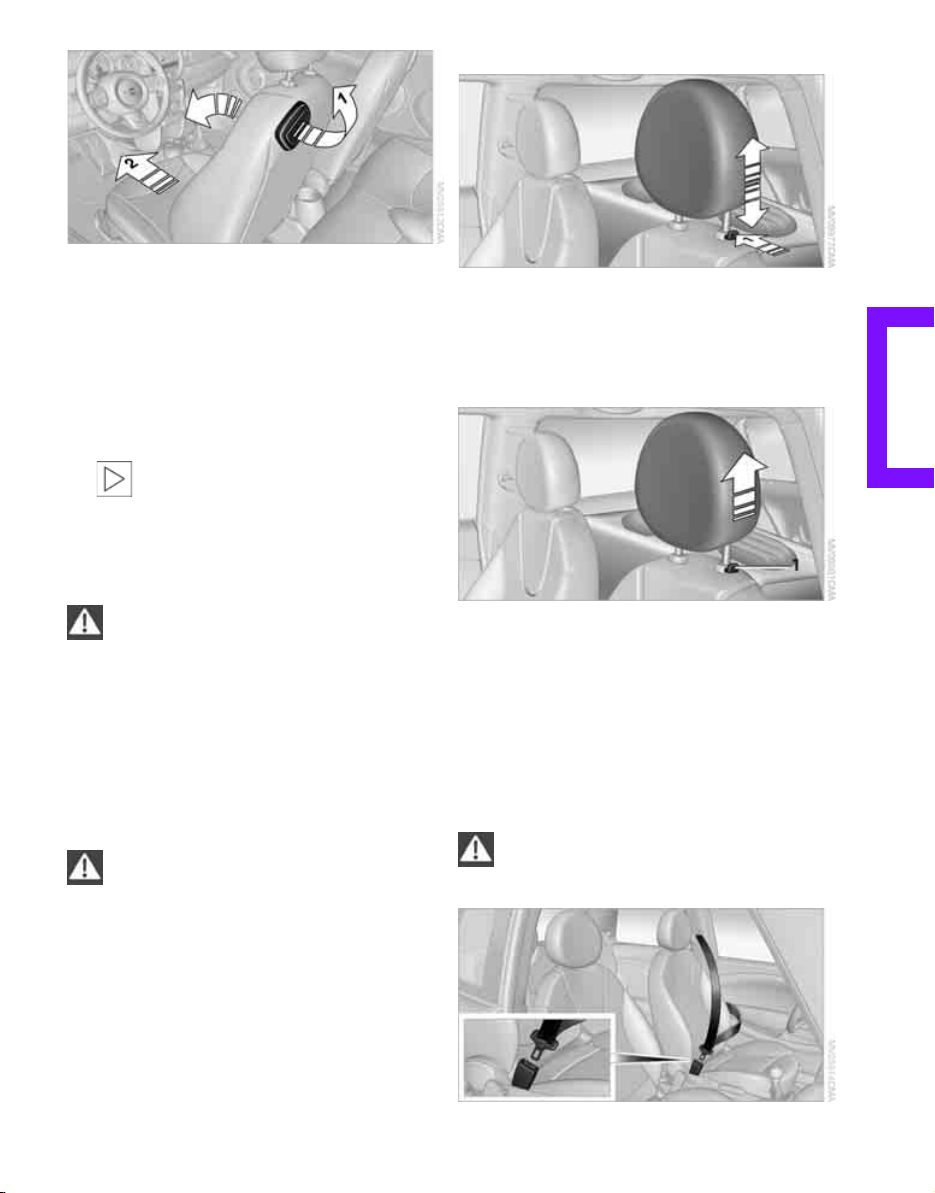
Height adjustment
To raise: pull up.
To lower: press the button, arrow 1, and slide
the head restraint down.
Removing
1. Pull up as far as it will go.
2. Fold the backrest forward slightly.
3. Press button 1 and pull the head restraint
out completely.
4. Fold back the backrest.
Head restraints
A correctly adjusted head restraint reduces the
risk of neck injury in the event of an accident.
Adjust the head restraint in such a way
that its center is at approx. ear level.
Otherwise, there is an increased risk of injury in
the event of an accident. Only remove a head
restraint if no one will be sitting on the seat in
question. Reinstall the head restraint before
transporting anyone on that seat. Otherwise,
the passenger will be without protection from
the head restraint.<
Safety belts
Observe the instructions on page 25 to
ensure the best possible personal protec-
tion.<
REFERENCE AT A GLANCECONTROLSDRIVING TIPSMOBILITY
27
Page 30
Before every drive, make sure that all occupants
Online Edition for Part no. 01 41 2 601 475 - © 11/08 BMW AG
wear their safety belts. Airbags complement the
safety belt as an additional safety device, but
they do not represent a substitute.
Closing
Make sure you hear the lock engage in the belt
buckle.
The upper belt anchor is suitable for adults of
any stature as long as the seat is adjusted properly, page 25.
Adjustments
Opening
1. Grasp the belt firmly.
2. Press the red button in the buckle.
3. Guide the belt into its reel.
Seat belt reminder
The indicator lamps come on and an
acoustic signal sounds. Check whether
the safety belt has been fastened cor-
rectly. The 'Fasten safety belts'
reminder is issued when the driver's safety belt
has not been fastened. The 'Fasten safety belts'
reminder is also activated at road speeds above
approx. 5mph or 8km/h if the front passenger's
safety belt has not been fastened, if objects are
placed on the front passenger seat, or if driver or
front passenger unfasten their safety belts.
Damaged safety belts
If the safety belts are damaged or stressed
in an accident: have the safety belt system
and its seat-belt tensioners replaced and the
belt anchors checked. Have this work carried out
only by a MINI Dealer or by a workshop that has
specially trained personnel working in accordance with the specifications of the MINI manufacturer, otherwise correct operation of these
safety systems is not ensured.<
Mirrors
Exterior mirrors
The front passenger's mirror is more con-
vex than the driver's mirror. The objects
seen in the mirror are closer than they appear.
Do not gauge your distance from traffic behind
you on the basis of what you see in the mirror;
otherwise there is an increased risk of an accident.<
1 Adjusting the left or right exterior mirror
2 Folding mirrors in and out
Manual adjustment
The mirrors can also be adjusted manually: press
the edge of the glass.
Folding mirrors in and out
Turn the knob beyond the pressure point in
direction 2. The mirrors can be folded in at road
speeds up to approx. 20 mph/30 km/h.
This can be beneficial in narrow streets, for
example, or for moving mirrors that were folded
in by hand back out into their correct positions.
Automatic heating
At outside temperatures below a certain limit,
both exterior mirrors are automatically heated
while the run position or the ignition is switched
on.
28
Page 31

Interior rearview mirror
Online Edition for Part no. 01 41 2 601 475 - © 11/08 BMW AG
To reduce glare from vehicles behind you when
you are driving at night:
Turn the knob.
Steering wheel
Adjustments
Do not adjust the steering wheel position
while the car is in motion, otherwise there
is a risk of accident due to an unexpected movement.<
1. Fold the lever down.
2. Move the steering wheel to the preferred
distance and angle to suit your seated position.
3. Swing the lever back up.
Do not use force to swing the lever
back up, otherwise the mechanism
will be damaged.<
REFERENCE AT A GLANCECONTROLSDRIVING TIPSMOBILITY
29
Page 32

Transporting children safely
Online Edition for Part no. 01 41 2 601 475 - © 11/08 BMW AG
The right place for children
Do not leave children unattended in the
vehicle, otherwise they could endanger
themselves and/or other persons by opening the
doors, for example.<
Children on the front passenger seat
Always transport children under the age of
13 or smaller than 5 ft/150 cm in a childrestraint system suitable for their age, weight
and size, and with the front passenger airbags
deactivated. Otherwise there is an increased risk
of injury in the event of an accident.<
Children 13 years of age or older must be buckled in with a safety belt as soon as there no
longer is any child-restraint system that is
appropriate for their age, size and weight.
Only mount child seats with the front pas-
senger seat backrest locked in an upright
position; otherwise there is an increased risk of
injury in the event of an accident.<
Transporting children safely
Front passenger airbags
Should it be necessary to use a child-
restraint system on the front passenger
seat, the front and side airbags must be deactivated. Otherwise there is an increased risk of
injury to the child if the airbags deploy, even if
the child is seated in a child-restraint system.<
For more information on automatic deactivation
of the front passenger airbags, refer to page 53.
Child-restraint systems, installation
Observe the child-restraint system manu-
facturer's instructions when selecting,
installing and using child-restraint systems.
Otherwise the protective effect may be diminished.<
On the front passenger seat
After installing a child-restraint system on
the front passenger seat, make sure that
the front and side airbags for the front passenger are deactivated, otherwise there is an
increased risk of injury if the airbags deploy.<
Child seat security
The safety belt for the front passenger can be
locked to prevent it from being pulled out when
it is used to secure child-restraint systems.
To lock the safety belt
1. Secure the child-restraint system with the
belt.
2. Pull the belt strap all the way out.
3. Allow the belt strap to retract and pull it taut
against the child-restraint system.
The safety belt is locked.
Unlocking the safety belt
1. Open the belt buckle.
2. Remove the child-restraint system.
3. Allow the safety belt strap to retract all the
way.
Child-restraint system with tether strap
Use the tether strap anchors to secure
child-restraint systems only, otherwise the
anchors could be damaged.<
30
Page 33

There is an additional anchor for child-restraint
Online Edition for Part no. 01 41 2 601 475 - © 11/08 BMW AG
systems with a tether strap, arrow.
Placement of the tether strap
1 Direction of travel
2 Head restraint
3 Tether strap hook
4 C pillar
5 Anchor
6 Seat backrest
7 Tether strap of the child-restraint system
Make sure the upper retaining strap does
not run over sharp edges and is not
twisted as it passes to the top anchor. Otherwise
the strap will not properly secure the childrestraint system in the event of an accident.<
1. Push the head restraint upward.
2. Guide the tether strap between the head
restraint holders.
3. Attach the tether strap to the anchor using
the hook.
4. Push the head restraint into its lowermost
position.
5. Pull the retaining strap tight.
REFERENCE AT A GLANCECONTROLSDRIVING TIPSMOBILITY
31
Page 34

Driving
Online Edition for Part no. 01 41 2 601 475 - © 11/08 BMW AG
Ignition lock
Inserting the key into the ignition lock
Driving
Insert the key all the way into the ignition lock:
The accessory position is switched on and individual electrical consumers are ready for operation.
Removing the key from the ignition lock
Press in the key briefly. It is ejected slightly.
The ignition is switched off at the same time if it
was still switched on.
You cannot take out the key unless the selector
lever is in the P position: interlock.
> Run position on/off
To switch to run position, depress the brake
in addition.
Accessory position
Individual electrical consumers are ready for
operation. The time and outside temperature
are displayed.
The accessory position is switched off automatically when the key is removed from the ignition.
Ignition on
When the ignition is switched on, most indicator
and warning lamps in indicator area 1, page 13,
light up for varying lengths of time.
When the ignition is switched off, the indicator
and warning lamps go out again.
If you do not intend to drive away, switch
off the ignition and any electrical consum-
ers you do not need to save battery power.<
Run position
You can drive off when the selector lever is in
position D or R and the parking brake has been
released.
Start/stop button
The following operating states can be reached
by pressing the start/stop button:
> Accessory on/off
> Ignition on/off
32
Switching TO RUN POSITION and driving off
Switching to run position
Key in ignition lock, refer to page 32.
1. Depress the brake.
2. Move the selector lever to position P.
Page 35

3. Press the start/stop button.
Online Edition for Part no. 01 41 2 601 475 - © 11/08 BMW AG
Never leave a vehicle unattended in the
run position; otherwise the vehicle represents a potential safety hazard.
Before leaving the car in the run position, move
the selector lever to position P and forcefully
apply the parking brake to prevent the car from
moving.<
Unlike combustion engines, the motor in your
MINI cannot be heard while the vehicle is standing. The pointer of the charge status display
points to the current value when the run position is switched on.
Driving off
Key in ignition lock, refer to page 32.
1. Switch to run position, refer to page 32.
2. Move the selector lever to position D or R,
refer to page 33.
3. Release the parking brake if applied, refer to
page 33.
4. Drive off.
Switching off RUN POSITION
Even after the run position is switched off,
the ventilation of the high voltage battery
may remain switched on in certain cases. The
ventilation switches off automatically after a few
minutes.<
Parking brake
The parking brake is primarily intended to prevent the vehicle from rolling while parked; it
brakes the rear wheels.
Applying
The lever locks in position automatically.
Releasing
Pull slightly upwards, press the button and lower
the lever.
In exceptional cases, if the parking brake
has to be used to slow or stop the car, do
not pull the lever up too hard. In doing so, continuously press the button of the parking brake
lever.
Otherwise, excessive force could lead to overbraking and loss of traction, i.e. fishtailing, at the
rear axle.<
Always take the key with you when you
leave the vehicle.
When parking, apply the parking brake forcefully, otherwise the vehicle could begin to roll.<
1. With the car at a standstill, move the selector
lever to position P.
2. Press the start/stop button.
3. Forcefully apply the parking brake.
Transmission positions
Parking the vehicle
To prevent the vehicle from rolling, always
select position P and apply the parking
brake before leaving the vehicle in the run position.<
33
REFERENCE AT A GLANCECONTROLSDRIVING TIPSMOBILITY
Page 36

Removing the key
Online Edition for Part no. 01 41 2 601 475 - © 11/08 BMW AG
1. Move the selector lever to position P.
2. Switch off run position.
3. Remove the key.
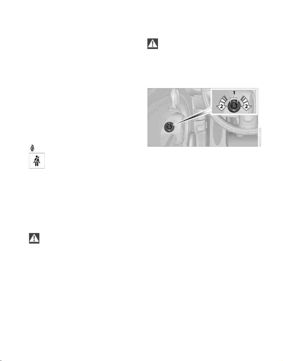
Selector lever positions
Driving
P R N D
The selector lever position is displayed.
Changing the selector lever positions
> The selector lever can only be moved out of
position P when the ignition or run position
is switched on.
> Before moving the lever away from P or N
with the vehicle stationary, first depress the
brake; otherwise the selector lever will
refuse to move: shiftlock.
A lock prevents accidental shifting into selector
lever positions R and P.
Overriding the selector lever lock
Press the button on the front of the selector
lever, arrow.
P Park
Select this only when the vehicle is stationary.
The transmission locks to prevent the drive
wheels from turning.
The selector lever is locked into position P when
the charging cable is connected. To change the
selector lever position, disconnect the charging
cable from the vehicle, refer to page 74.
R Reverse
Select this only when the vehicle is stationary.
N Neutral
Select this when you are in a car wash, for example. The vehicle can roll.
When the vehicle is stationary and in run position, vehicle is stationary, N is automatically
engaged if all of the following conditions are
met:
> The driver's safety belt is not buckled.
> The accelerator and brake pedal are not
depressed.
> The driver's door is opened.
Selector lever position N flashes in the display,
refer to page 34. To change to another position,
the selector lever must first be moved to N.
D Drive
Position for normal vehicle operation.
Manually unlock the selector lever lock
If the power supply is interrupted, e.g. if
the 12 volt battery is dead or disconnected, or if there is an electrical malfunction,
the selector lever lock must be unlocked manually; otherwise the front wheels are locked up
and the vehicle cannot be towed.<
Only unlock the selector lever lock manually
when the vehicle is to be towed. Do not forget to
firmly apply the parking brake prior to the tow,
otherwise the vehicle may roll away.
34
Page 37

1. Unclip the sleeve of the selector lever.
Online Edition for Part no. 01 41 2 601 475 - © 11/08 BMW AG
2. Pull the sleeve up over the selector lever
until the sleeve is inside out. Disconnect the
cable connector if necessary.
3. Take the hub cover remover 1 out of the
glove compartment and insert it in the loop
on the front passenger side.
4. Pull the loop up.
5. Move the selector lever into the desired
position by pressing the button on the front
of the selector lever.
Driving with an electric motor
Take your foot off of the accelerator care-
fully since the braking action of the motor
can be stronger than that in vehicles with combustion engines. Otherwise an unexpected
reduction in speed may cause you to become an
obstacle to other road users.<
Energy recovery
Your MINI makes it possible to convert kinetic
energy into electrical energy and to partially
recharge the high voltage battery in this way.
Energy can be recovered when the following
conditions are met:
> The vehicle is in motion.
> Selector lever position D is engaged.
> The accelerator is not depressed at all, or
only within the first third of the accelerator
travel distance.
Energy recovery and accelerator
position
The vehicle is braked during energy recovery.
The deceleration depends on the accelerator
position.
Accelerator position:
1 Deceleration
The less the accelerator is depressed, the
greater the deceleration.
This charges the high voltage battery using
the recovered energy.
2 Constant speed or acceleration
The high voltage battery supplies energy.
When you raise your foot off of the accel-
erator, the vehicle deceleration is similar
to that caused by light braking. The brake lamps
go on although the brake pedal is not
depressed.<
Energy recovery cannot take place when:
> the selector level is in position N or R.
> Dynamic Stability Control is active.
> the temperature of the high voltage battery
is below +257/-46
In winter, energy recovery may not be available immediately after the vehicle is started,
e.g. if the vehicle was standing outside overnight.
Be ready to apply the brakes at all
times, since energy recovery is not a
substitute for braking action. Otherwise an
accident may occur.<
> the temperature of the high voltage battery
is above +1207/+49 6
REFERENCE AT A GLANCECONTROLSDRIVING TIPSMOBILITY
35
Page 38

Electric motor noise
Online Edition for Part no. 01 41 2 601 475 - © 11/08 BMW AG
The electric motor in your MINI makes far less
noise than a combustion engine. Please take
this into consideration when driving, as other
road users, e. g. pedestrians or bicyclists, may
not hear your MINI; adapt your driving style
Driving
accordingly.
Hot high voltage battery
In rare cases, the high voltage battery of your
MINI may become very hot. Depending on the
temperature of the high voltage battery, your
MINI may be affected as follows:
Ventilation of the high voltage battery
switches on
The ventilation of the high voltage battery is
clearly audible in the vehicle interior.
Energy recovery is reduced
To cool the high voltage battery, energy recovery is no longer possible.
When the yellow warning lamp lights
up, energy recovery is only possible to a
limited degree. In special cases, the
usual deceleration may be greatly minimized or
switched off altogether.
Be ready to brake at all times as the
braking effect of the electric motor due
to energy recovery will no longer be available.
The vehicle may roll further than usual even if
the accelerator is not depressed. This may
endanger other road users.<
Reducing the maximum speed
When the high voltage battery is very hot, the
maximum speed is limited to approx. 10 mph/
16 km/h.
Continue driving only if you do not
obstruct traffic, otherwise other road users
could be endangered.<
Turn signals/ headlamp flasher
1 Turn signal indicator
2 Headlamp flasher
Using turn signals
Press the lever beyond the resistance point.
To turn off manually, press the lever to the resistance point.
Unusually rapid flashing of the indicator
lamp indicates that an indicator bulb has
failed.<
Indicating a turn briefly
Press the lever as far as the resistance point for
as long as you wish to indicate a turn.
Triple turn signal activation
Press the lever as far as the resistance point.
You can set whether the turn signal is to flash
once or three times.
1. Switch on the ignition, refer to page 32.
2. Briefly press the button in the turn indicator
lever repeatedly until "SET/INFO" is displayed.
36
Page 39

3. Press and hold the button until the display
Online Edition for Part no. 01 41 2 601 475 - © 11/08 BMW AG
changes.
4. Briefly press the button repeatedly until the
symbol and "SET" are displayed.
5. Press and hold the button until the display
changes.
6. Briefly press the button repeatedly until the
display shows the illustrated symbol, arrow.
Wiper system
1 Switching on the wipers
2 Switching off wipers or brief wipe
3 Activating/deactivating intermittent mode
4 Cleaning windshield and headlamps
Switching on wipers
Press the lever upward, arrow 1.
The lever automatically returns to its initial position when released.
Normal wiper speed
Press once.
The system switches to intermittent operation
when the vehicle is stationary.
7. Press and hold the button until the display
changes.
8. Briefly press the button to select:
>
Brief indication of a turn.
>
Triple turn signal.
9. Press and hold the button until the display
changes. The setting is stored.
Fast wiper speed
Press twice or press beyond the resistance point.
The system switches to normal speed when the
vehicle is stationary.
Brief wipe
Press the lever downward once, arrow 2.
Clean windshield and headlamps
Pull the lever, arrow 4.
Washer fluid is sprayed onto the windshield and
the wipers are operated briefly.
When the vehicle lighting system is switched on,
the headlamps are cleaned at regular and
appropriate intervals.
The headlamps cannot be cleaned when the
bonnet is open.
37
REFERENCE AT A GLANCECONTROLSDRIVING TIPSMOBILITY
Page 40

Do not use the washers when the washer
Online Edition for Part no. 01 41 2 601 475 - © 11/08 BMW AG
fluid reservoir is empty, otherwise you will
damage the washer pump.
Only use the washers if the bonnet has been
completely closed, otherwise the headlamp
*
washer system
the washers if there is any danger that the fluid
Driving
will freeze on the windshield. If you do, your
vision could be obscured. For this reason, use
antifreeze.<
may be damaged. Do not use
Window washer nozzles
The window washer nozzles are heated automatically while run position or the ignition is
switched on.
Rear window wiper
0 Rear wipers parked
1 To switch on intermittent wipe :
Turn the cap to level 1.
Operation is continuous in reverse gear.
Cleaning the rear window
2 To clean the rear window during intermit-
tent wipe :
Turn the cap further to level 2 and hold it
there.
3 To clean the rear window when wipers are
parked :
Turn the cap to level 3 and hold it there.
Do not use the washers when the washer
fluid reservoir is empty, otherwise you will
damage the washer pump.<
Washer fluid
Washer fluid antifreeze is flammable.
Therefore, keep it away from ignition
sources, store it only in the closed original container and keep it out of reach of children,
otherwise there is a risk of personal injury.
Comply with the instructions on the container.<
Washer fluid reservoir
Ensure that washer fluid does not over-
flow or spill into the motor compartment
as this may damage the high voltage system and
the vehicle electronics.<
Fill with water and, if required, with a washer
antifreeze, according to manufacturer's recommendations.
Mix the water and antifreeze before filling
the washer fluid reservoir to make sure
the correct concentration is maintained.<
Capacity
With headlamp washer system:
approx. 3.3 US quarts/3.2 liters.
38
Page 41

Everything under control
Online Edition for Part no. 01 41 2 601 475 - © 11/08 BMW AG
Odometer, outside temperature display, clock
1 Outside temperature display and clock or
current speed
2 Odometer and trip odometer
3 Resetting the trip odometer
Units of measure
Select the respective units of measure, miles or
km for the odometer as well as 7 or 6 for the
outside temperature, page 42.
Outside temperature display, time
Setting the time, refer to page 45.
1. Press the button in the turn indicator lever
repeatedly until the current speed appears
in the lower display.
2. Wait for the speed display to automatically
move to the upper display.
The outside temperature then appears in the
lower display.
Odometer and trip odometer
Resetting the trip odometer
With the ignition switched on, press button 3 in
the charge status display.
When the vehicle is parked
To display the time, outside temperature and
odometer briefly after the key is removed from
the ignition lock:
Press button 3 in the charge status display.
Charge status display
Outside temperature warning
When the displayed temperature sinks to
approx. +377/+36, a signal sounds and a
warning lamp lights up. There is an increased
risk of black ice.
Black ice can also form at temperatures
above +37 7/+36. You should therefore
drive carefully on bridges and shaded roads, for
example; as otherwise there is an increased risk
of an accident.<
Current vehicle speed
To have the current speed shown in the upper
display otherwise serving for the outside temperature display and clock.
The display shows the percentage to which the
high voltage battery is charged.
Information on charging the high voltage battery can be found on page 72.
REFERENCE AT A GLANCECONTROLSDRIVING TIPSMOBILITY
39
Page 42

Energy consumption
Online Edition for Part no. 01 41 2 601 475 - © 11/08 BMW AG
indicator
The energy consumption indicator in the speedometer indicates whether energy is being consumed and recovered.
The high voltage battery is charged by means of
energy recovery during driving.
1 Energy consumption
2 Energy recovery
The more energy is consumed and recovered,
the more elements light up.
Everything under control
Computer
In the charge status display
Press the button in the turn indicator lever
repeatedly to call up various items of information.
The following items of information are displayed
in the order listed:
> Cruising range
> Average energy consumption
> Charge status, temperature of the high volt-
age battery
*
> Average speed
> Current vehicle speed
To set the corresponding units of measure, refer
to Formats and units of measure on page 42.
Cruising range
The display indicates the estimated range provided by the energy stored in the high voltage
battery. The range is calculated on the basis of
the way the car has been driven over the last
18 miles/30 km and current charge status.
Average energy consumption
Calculated for the time over which the vehicle is
driven.
To reset the average energy consumption: press
the button in the turn indicator lever for approx.
2seconds.
Average speed
Periods in which the vehicle is parked and not in
run position are not included in the average
speed calculations.
To reset average speed: press the button in the
turn indicator lever for approx. 2 seconds.
Current vehicle speed
To have the current speed shown in the upper
display otherwise serving for the outside temperature display and clock.
1. Press the button in the turn indicator lever
repeatedly until the current speed appears
in the lower display.
2. Wait for the speed display to automatically
move to the upper display.
The outside temperature then appears in the
lower display of the computer.
40
Page 43

Settings and information
Online Edition for Part no. 01 41 2 601 475 - © 11/08 BMW AG
Operating principle
Certain settings and information are only available when the ignition is switched on, the vehicle is at a standstill and the doors are closed.
1 Button for:
> Selecting display
> Setting values
> Confirming selected display or set values
> Calling up computer information 40
2 Adjusting the charging current 72
3 Calling up Check Control 46
4 Displaying vehicle check 46
5 Resetting the Tire Pressure Monitor 49
6 Setting formats and units of measure, reset-
ting to factory settings 43
7 Adjusting settings
> Confirmation signals when locking and
unlocking the vehicle 20
> Response during unlocking
procedure 19
> Automatic locking 22
> Pathway lighting 55
> Daytime running lamps 56
> Triple turn signal activation 36
8 Setting the time 45
9 Setting the date 45
10 Exiting the menu
REFERENCE AT A GLANCECONTROLSDRIVING TIPSMOBILITY
41
Page 44

Exiting displays
Online Edition for Part no. 01 41 2 601 475 - © 11/08 BMW AG
1. Briefly press the button in the turn indicator
lever repeatedly until "HOME" is displayed.
2. Press the button for a longer period.
The display again shows the outside temperature and the time.
Displays are also exited if no entries are made
for approx. 8 seconds.
Next setting or item of information
Everything under control
1. Switch on the ignition, refer to page 32.
2. Briefly press the button in the turn indicator
lever repeatedly until "SET/INFO" is displayed.
3. Press and hold the button until the display
changes.
4. Briefly press the button repeatedly until the
symbol and "SET" are displayed.
1. Within a setting or item of information,
briefly press the button in the turn indicator
lever repeatedly until "NEXT" is displayed.
2. Press the button for a longer period.
The display changes directly to the next setting
or item of information.
Formats and units of measure
To set the formats and units of measure. The settings are stored for the remote control currently
in use, refer also to Personal Profile on page 18.
42
5. Press and hold the button until the display
changes.
6. Briefly press the button repeatedly until the
display shows the illustrated symbol, arrow.
> Energy consumption: Ah/100 km,
Ah/100 mls
> Distance covered: mls, km
> Time: 12h, 24h mode
Page 45

> Date: day.month dd.mm,
Online Edition for Part no. 01 41 2 601 475 - © 11/08 BMW AG
month/day mm/dd
> Temperature: 7, 6
7. Press and hold the button until the display
changes.
8. Press the button briefly to change the for-
mat or unit of measure.
9. Press and hold the button until the display
changes.
The settings are stored.
5. Briefly press the button repeatedly until
"RESET" is displayed.
Resetting to factory settings
The settings for formats and units of measure
can be reset to the factory settings. The settings
are stored for the remote control currently in
use, refer also to Personal Profile on page 18.
1. Briefly press the button in the turn indicator
lever repeatedly until "SET/INFO" is displayed.
2. Press and hold the button until the display
changes.
3. Briefly press the button repeatedly until the
symbol and "SET" are displayed.
6. Press and hold the button until the display
changes to the first setting.
The settings are reset.
Service requirements
The remaining driving distance and the date of
the next scheduled service are briefly displayed
immediately after you switch on run position or
the ignition.
The extent of service work required can be
read out from the remote control by your
MINI Dealer.<
Displaying vehicle check
For certain maintenance operations, you can
view the respective distance remaining or due
date individually in the charge status display.
4. Press and hold the button until the display
changes.
REFERENCE AT A GLANCECONTROLSDRIVING TIPSMOBILITY
43
Page 46

1. Switch on the ignition, refer to page 32.
Online Edition for Part no. 01 41 2 601 475 - © 11/08 BMW AG
2. Briefly press the button in the turn indicator
lever repeatedly until "SET/INFO" is displayed.
3. Press and hold the button until the display
changes.
Possible displays
Everything under control
4. Briefly press the button repeatedly until the
corresponding symbol and "SERVICE-INFO"
are displayed.
5. Press and hold the button until the display
changes.
6. Briefly press the button to display the indi-
vidual service items, refer to the following
information.
1 Button for selecting information
2 Vehicle check
3 Roadworthiness test
4 Brake fluid
5 Front brakes
6 Rear brakes
7 Exit display 42
44
8 Next setting or item of information 42
More information on the MINI Maintenance System can be found on page 84.
Page 47

Clock
Online Edition for Part no. 01 41 2 601 475 - © 11/08 BMW AG
Date
Setting the time
To set the 12h/24h mode, refer to Formats and
units of measure on page 42.
1. Briefly press the button in the turn indicator
lever repeatedly until "SET/INFO" is displayed.
2. Press and hold the button until the display
changes.
3. Briefly press the button repeatedly until the
symbol and "SET" are displayed.
Setting the date
To set the dd/mm or mm/dd date format, refer
to Formats and units of measure on page 42.
1. Briefly press the button in the turn indicator
lever repeatedly until "SET/INFO" is displayed.
2. Press and hold the button until the display
changes.
3. Briefly press the button repeatedly until the
symbol and "SET" are displayed.
4. Press and hold the button until the display
changes.
5. Press the button to set the hours.
6. Wait for the display to change to minutes.
7. Press the button to set the minutes.
8. Wait for the display to change.
The settings are stored.
4. Press and hold the button until the display
changes.
5. Press the button to set the day of the month.
6. Wait for the display to change to month.
7. Set the month and year in the same way.
8. Wait for the display to change.
The settings are stored.
REFERENCE AT A GLANCECONTROLSDRIVING TIPSMOBILITY
45
Page 48

Check Control
Online Edition for Part no. 01 41 2 601 475 - © 11/08 BMW AG
The concept
The Check Control monitors vehicle functions
and alerts you to any malfunctions in the systems monitored. Check Control messages
involve indicator or warning lamps in the displays and, in some circumstances, an acoustic
signal. To adjust the volume of the signal, refer
to the Owner's Manual for Radio.
Indicator and warning lamps can light up in various combinations and colors in the indicator
areas 1 and 2.
Everything under control
What to do in case of a malfunction
The meaning of each lamp in the event of a malfunction and tips on how to respond are listed
starting on page 96.
Other Check Control messages are automatically
hidden after approx. 20 seconds, but remain
stored.
This symbol indicates that Check Control
messages have been stored. Check Control messages can be viewed whenever it is convenient.
Viewing stored Check Control messages
Stored Check Control messages can only be displayed if the driver's door is closed.
1. Briefly press the button in the turn indicator
lever repeatedly until "SET/INFO" is displayed.
Hiding Check Control messages
Press the button in the turn indicator lever.
Some Check Control messages are displayed
until the malfunctions have been rectified. They
cannot be hidden. If several malfunctions occur
at the same time, they are displayed in succession.
46
2. Press and hold the button until the display
changes.
Page 49

3. Press the button repeatedly until the display
Online Edition for Part no. 01 41 2 601 475 - © 11/08 BMW AG
shows the corresponding symbol and
"CHECK INFO".
4. Hold the button down.
"CHECK OK" appears if there are no Check
Control messages.
If a Check Control message has been stored,
the corresponding message is displayed.
5. Briefly press the button to check for other
messages.
REFERENCE AT A GLANCECONTROLSDRIVING TIPSMOBILITY
47
Page 50

Technology for driving comfort and
Online Edition for Part no. 01 41 2 601 475 - © 11/08 BMW AG
safety
Driving stability control systems
Your MINI has a number of systems that help to
maintain the vehicle's stability even in adverse
driving conditions.
The laws of physics cannot be repealed,
even with driving stability control systems.
An appropriate driving style always remains the
responsibility of the driver. Therefore do not
reduce the additional safety margin by engaging
in hazardous driving thereby running the risk of
an accident.<
Antilock Brake System ABS
ABS prevents locking of the wheels during braking. Safe steering response is maintained even
during full braking. Active safety is thus
increased.
Braking safely, refer to page 66.
Among others, ABS includes the following functions:
> Cornering Brake Control CBC
> Electronic brake-force distribution EBV
> Brake Assist
Cornering Brake Control CBC
Driving stability and steering characteristics are
further enhanced while braking in turns or
during a lane change.
Electronic brake-force distribution EBV
The system controls the brake pressure in the
Technology for driving comfort and safety
rear wheels to ensure stable braking behavior.
Brake Assist
Rapidly depressing the brake causes this system
to automatically develop maximum braking
force. Thus, the system helps keep braking dis-
tance to a minimum. At the same time, all the
benefits provided by ABS are exploited.
Do not reduce the pressure on the brake for the
duration of the full braking application.
Dynamic Stability Control DSC
DSC prevents the driving wheels from losing
traction when you pull away from rest or accelerate. The system also recognizes unstable driving conditions, for example if the rear of the car
is about to swerve or if momentum is acting at
an angle past the front wheels. In these cases,
DSC helps the vehicle maintain a safe course
within physical limits by reducing motor output
and through braking actions at the individual
wheels.
DSC also encompasses the following functions:
> Antilock Brake System ABS
> Electronic brake-force distribution EBV
> Brake Assist
> Cornering Brake Control CBC
> Hill Start Assist
Hill Start Assist
Hill Start Assist aids you in comfortably driving
off on inclines. It is not necessary to use the
parking brake for this.
1. Hold the MINI with the brake.
2. Release the brake and immediately drive
off.
Hill Start Assist holds the car in place for approx.
2 seconds after the brake is released.
Depending on the load and gradient, the
vehicle can roll backward slightly during
this period. After you release the brake, immediately start driving since the hill start assist only
holds the vehicle for about 2 seconds, and it will
start to roll backwards.<
48
Page 51

Tire Pressure Monitor
Online Edition for Part no. 01 41 2 601 475 - © 11/08 BMW AG
TPM
The concept
TPM checks the inflation pressures of the four
mounted tires. The system notifies you if there is
a significant loss of pressure in one or more tires.
Functional requirement
In order to assure the reliable reporting of a flat
tire, the system must be reset while all tire inflation pressures are correct.
Always use wheels with TPM electronics. Otherwise, the system may malfunction.
Each time a tire inflation pressure has
been corrected or a wheel or tire has been
changed, reset the system.<
System limitations
TPM cannot warn you in advance of sudden severe tire damage caused by outside
influences.<
The system does not work correctly if it has not
been reset; for example, a flat tire may be indicated even though the tire inflation pressures
are correct.
The system is inactive and cannot indicate a flat
tire if a wheel without TPM electronics has been
mounted, or if TPM is temporarily malfunctioning due to other systems or devices using the
same radio frequency.
Using the button in the turn indicator
lever
1. Switch the vehicle to run position but do not
start driving.
2. Briefly press the button in the turn indicator
lever repeatedly until "SET/INFO" is displayed.
3. Press and hold the button until the display
changes.
4. Repeatedly press the button briefly until the
symbol for Tire Pressure Monitor and
"ACTIVE" are displayed.
The Tire Pressure Monitor can be reset using
"RESET".
Resetting the system
Each time a tire inflation pressure has
been corrected or a wheel or tire has been
changed, reset the system.<
5. Press and hold the button until "RESETTING"
appears.
REFERENCE AT A GLANCECONTROLSDRIVING TIPSMOBILITY
49
Page 52

6. Start driving.
Online Edition for Part no. 01 41 2 601 475 - © 11/08 BMW AG
After driving a few minutes, the set inflation
pressures in the tires are accepted as the target values to be monitored. The system
reset is completed during your drive, and
c an b e int errupte d a t any ti me. Wh en d rivi ng
resumes, the reset is continued automatically. The indicator lamp goes out after the
system reset is completed.
Message for low tire inflation pressure
The warning lamps come on in yellow
and red. An acoustic signal also sounds.
There is a flat tire or substantial loss of
tire pressure.
1. Cautiously reduce speed to below 50 mph/
80 km/h. Avoid sudden braking and steering
maneuvers. Do not exceed a speed of
50 mph/80 km/h.
Do not contin ue driving if the vehicle is
not equipped with Run-Flat Tires,
otherwise a serious accident could result.<
2. If there is a complete loss in tire inflation
pressure, 0 psi/0 kPa, you can continue driving for about another 95 miles/150 km.
Drive cautiously and do not exceed a
speed of 50 mph/80 km/h, otherwise an
accident may occur. In the event of pressure
loss, vehicle handling changes. This includes
reduced tracking stability in braking, extended
braking distance and altered natural steering
characteristics.
If unusual vibration or loud noises occur during
the journey, this may be an indication that the
damaged tire has finally failed. Reduce the vehicle speed and stop as soon as possible. Otherwise, sections of the tire may come loose and
cause accidents. Do not continue driving and
contact your MINI Dealer.<
Technology for driving comfort and safety
Malfunction
The small warning lamp flashes in yellow and then lights up continuously; the
larger warning lamp comes on in yellow.
No punctures can be detected.
This type of message is shown in the following
situations:
> If there is a malfunction.
Have the system checked.
> If a wheel without TPM electronics has been
mounted.
> If TPM is temporarily malfunctioning due to
other systems or devices using the same
radio frequency.
Message for unsuccessful system reset
Both warning lamps come on in yellow.
The system is not reset after a wheel has
been changed, for example.
Check the tire inflation pressure and
reset the system, refer to the Owner's Manual
for Vehicle.
Declaration according to NHTSA/
FMVSS 138 Tire Pressure Monitoring
Systems
Each tire, including the spare, should be
checked monthly when cold and inflated to the
inflation pressure recommended by the vehicle
manufacturer on the vehicle placard or tire inflation pressure label. If your vehicle has tires of a
different size than the size indicated on the vehicle placard or tire inflation pressure label, you
should determine the proper tire inflation pressure for those tires. As an added safety feature,
your vehicle has been equipped with a tire pressure monitoring system TPMS that illuminates a
low tire pressure telltale when one or more of
your tires are significantly under-inflated.
Accordingly, when the low tire pressure telltale
illuminates, you should stop and check your tires
as soon as possible, and inflate them to the
proper pressure. Driving on a significantly
under-inflated tire causes the tire to overheat
and can lead to tire failure. Underinflation also
reduces vehicle efficiency and tire tread life, and
may affect the vehicle's handling and stopping
ability. Please note that the TPMS is not a substitute for proper tire maintenance, and it is the
driver's responsibility to maintain correct tire
pressure, even if underinflation has not reached
50
Page 53

the level at which the TPMS low tire pressure tell-
Online Edition for Part no. 01 41 2 601 475 - © 11/08 BMW AG
tale illuminates.
The TPMS malfunction indicator is combined
with the low tire pressure telltale. When the system detects a malfunction, the telltale will flash
for approximately one minute and then remain
continuously lit. This sequence will continue
upon subsequent vehicle startups as long as the
malfunction exists. When the malfunction indicator is illuminated, the system may not be able
to detect or signal low tire pressure as intended.
TPMS malfunctions may occur for a variety of
reasons, including the installation of replacement or alternate tires or wheels on the vehicle
that prevent the TPMS from functioning properly. Always check the TPMS malfunction telltale
after replacing one or more tires or wheels on
your vehicle to ensure that the replacement or
alternate tires and wheels allow the TPMS to
continue to function properly.
REFERENCE AT A GLANCECONTROLSDRIVING TIPSMOBILITY
51
Page 54

Airbags
Online Edition for Part no. 01 41 2 601 475 - © 11/08 BMW AG
The following airbags are located under the
marked covers:
Protective action
Observe the instructions on page 25 to
ensure the best possible personal protec-
tion.<
The front airbags help protect the driver and
front passenger by responding to frontal
impacts in which safety belts alone cannot provide adequate restraint. When needed, the head
and side airbags help provide protection in the
event of side impact. The relevant side airbag
supports the side upper body area. The head air
bag supports the head.
The airbags are designed to not be triggered in
every type of collision, e.g. not in minor accidents, certain rollover situations or rear impacts.
Do not apply adhesive materials to the
cover panels of the airbags, cover them or
modify them in any other way.
Keep the dashboard and window on the front
passenger side free from obstruction, i.e. do not
cover it with adhesive film or coverings, and do
not affix any holders such as for a navigation
device or a mobile phone.
Do not attach seat covers, cushions or other
Technology for driving comfort and safety
objects not specifically approved for seats with
integral side airbags to the front seats. Do not
hang items of clothing such as coats or jackets
over the backrests. Do not attempt to remove
the airbag retention system from the vehicle. Do
not modify the individual components of the
system or its wiring in any way. This includes the
upholstered covers on the steering wheel,
1 Front airbags
2 Side airbags in backrests
3 Front head airbags
instrument panel, seats and roof posts, as well as
the sides of the roof lining. Do not attempt to
remove or dismantle the steering wheel.
Do not touch the individual components immediately after the system has been triggered,
because there is a danger of burns.
In the event of malfunctions, deactivation, or
triggering of the airbag restraint system, have
the testing, repair, removal, and disposal of airbag generators executed only by a MINI Dealer
or a workshop that works according to repair
procedures of the manufacturer of your MINI
with correspondingly trained personnel and has
the required explosives licenses. Otherwise,
unprofessional attempts to service the system
could lead to failure in an emergency or undesired airbag activation, either of which could
result in personal injury.<
Warning notices and information about the airbags can also be found on the sun visors.
52
Page 55

Automatic deactivation of the front
Online Edition for Part no. 01 41 2 601 475 - © 11/08 BMW AG
passenger airbags
An analysis of the impression in the front passenger seat cushion determines whether and
how the seat is occupied. The front and side airbags for the front passenger are activated or
deactivated by the system accordingly.
The indicator lamp above the interior rear-
view mirror shows the current status of
the front passenger airbags, deactivated or activated, refer to Status of front passenger airbags
below.<
Before transporting a child on the front
passenger seat, read the safety precautions and handling instructions under Transporting children safely, page 30.
The front and side airbags can also be deactivated by adolescents and adults sitting in certain
positions; the indicator lamp for the front passenger airbags comes on. In such cases, the passenger should change his or her sitting position
so that the front passenger airbags are activated
and the indicator lamp goes out. If the desired
airbag status cannot be achieved by changing
the sitting position, do not transport passengers
on the front passenger seat. Do not attach
covers, cushions, ball mats or other items to the
front passenger seat unless they are specifically
recommended by the manufacturer of your
MINI. Do not place any items under the seat
which could press against the seat from below.
Otherwise a correct analysis of the seat cushion
is not ensured.<
with whether and how the front passenger seat
is occupied. The indicator lamp shows whether
the front passenger airbags are activated or
deactivated.
> The indicator lamp comes on as intended
when a child in a specially designated childrestraint system is detected on the seat.
The front and side airbags for the front passenger are not activated.
Most child seats are detected by the
system. This particularly applies to
child seats that were required by the NHTSA
at the time of manufacture of the vehicle.
After installing a child's seat, check that the
indicator lamp for the front passenger airbags comes on. It indicates that the child's
seat has been detected and that the front
passenger airbags are deactivated.<
> Th e i nd ic at or la mp do es no t c om e o n a s l on g
as a person of sufficient size and in a correct
sitting position is detected on the seat.
The front and side airbags for the front passenger are activated.
> The indicator lamp does not come on if the
seat is empty.
The front and side airbags for the front passenger are not activated.
Operational readiness of airbag system
Status of front passenger airbags
The indicator lamp for the front passenger airbags shows the functional status of the front
passenger's front and side airbag s in accordance
Beginning with the accessory position, page 32,
the warning lamp comes on briefly to indicate
that the entire airbag system and the belt tensioners are operational.
REFERENCE AT A GLANCECONTROLSDRIVING TIPSMOBILITY
53
Page 56

Airbag system malfunction
Online Edition for Part no. 01 41 2 601 475 - © 11/08 BMW AG
> The warning lamp does not come on when
accessory or the ignition is switched on.
> The warning lamp stays lit continuously.
In the event of a fault in the airbag system,
have it checked without delay, otherwise
there is the risk that the system will not function
as intended even if a sufficiently severe accident
occurs.<
Technology for driving comfort and safety
54
Page 57

Lamps
Online Edition for Part no. 01 41 2 601 475 - © 11/08 BMW AG
Parking lamps/low beams
0 Lamps off and daytime running lamps
1 Parking lamps and daytime running lamps
2 Low-beam headlamps and welcome lamps
When you open the driver's door with the ignition switched off, the exterior lighting is automatically switched off if the light switch is in
position 0 or 2.
Switch on the parking lamps if necessary, switch
position 1.
Parking lamps
Turn the light switch to position 1.
The front, rear and side vehicle lighting is
switched on.
Activation of lights on one side of the vehicle for
parking, page 57.
The parking lamps discharge the 12 volt
battery. Therefore, do not leave them on
for unduly long periods of time, otherwise the
battery might not have enough power to start
the motor.<
interior lamps come on for a certain time as soon
as the vehicle is unlocked.
Pathway lighting
If you activate the headlamp flasher after parking the car, with the lights switched off, the low
beams come on and remain on for a certain
time.
The setting is stored for the remote control in
use, refer to Personal Profile, page 18.
Setting the duration or deactivating the
function
1. Switch on the ignition, refer to page 32.
2. Briefly press the button in the turn indicator
lever repeatedly until "SET/INFO" is displayed.
3. Press and hold the button until the display
changes.
4. Briefly press the button repeatedly until the
symbol and "SET" are displayed.
Low beams
Turn the light switch to position 2.
The low beams come on when the ignition is on.
Welcome lamps
If you leave the light switch in the low beam or
automatic headlamp control position when you
switch off the ignition, the parking lamps and
5. Press and hold the button until the display
changes.
55
REFERENCE AT A GLANCECONTROLSDRIVING TIPSMOBILITY
Page 58

6. Briefly press the button repeatedly until the
Online Edition for Part no. 01 41 2 601 475 - © 11/08 BMW AG
display shows the illustrated symbol.
Lamps
7. Press and hold the button until the display
changes.
8. Briefly press the button to select:
>
The function is deactivated.
> ...
Select the corresponding duration, e.g.
40 seconds.
9. Press the button for a longer period.
The setting is stored.
Daytime running lamps
The light switch can remain in the lamps off or
parking lamps position.
In the lamps off position, the exterior lighting is
automatically switched off after the vehicle is
parked. In the parking lamps position, the parking lamps will stay on after the ignition is
switched off.
Switch on the parking lamps separately if
needed.
1. Switch on the ignition, refer to page 32.
2. Briefly press the button in the turn indicator
lever repeatedly until "SET/INFO" is displayed.
3. Press and hold the button until the display
changes.
4. Briefly press the button repeatedly until the
symbol and "SET" are displayed.
5. Press and hold the button until the display
changes.
6. Briefly press the button repeatedly until the
display shows the illustrated symbol, arrow.
Activating/deactivating daytime
running lamps
The setting is stored for the remote control in
use, refer to Personal Profile, page 18.
56
7. Press and hold the button until the display
changes.
Page 59

8. Briefly press the button to select:
Online Edition for Part no. 01 41 2 601 475 - © 11/08 BMW AG
>
Daytime running lamps activated.
>
Daytime running lamps deactivated.
9. Press the button for a longer period.
The setting is stored.
Xenon lamps
The headlamp range is controlled automatically,
e.g. when accelerating and braking, and for different cargo loads.
High beams/roadside parking lamps
1 Turn signals/roadside parking lamps
2 Switching on high beams
3 Switching off high beams/headlamp flasher
Roadside parking lamps, left or right
The vehicle can be illuminated on one side for
parking. Comply with local regulations when
doing so.
Switching on
After parking the vehicle, press the lever up or
down, arrow 1.
The roadside parking lamps discharge the
12 volt battery. Therefore, do not leave
them on for unduly long periods of time, otherwise the battery might not have enough power
to start the motor.<
Switching off
Press the lever up or down to the pressure point.
Instrument lighting
You can adjust the brightness of the instrument
lighting only when the parking lamps or the low
beams are on.
Increasing brightness
Press and hold the button until the desired
brightness is reached.
Reducing brightness
Press the button briefly.
The brightness decreases every time the button
is pressed briefly.
Interior lamps
The interior lamps and footwell lamps are controlled automatically.
To avoid draining the 12 volt battery, all
lamps inside the vehicle are switched off
approx. 8 minutes after the ignition is switched
off, refer to Start/stop button on page 32.<
REFERENCE AT A GLANCECONTROLSDRIVING TIPSMOBILITY
57
Page 60

Switching interior lamps on/off manually
Online Edition for Part no. 01 41 2 601 475 - © 11/08 BMW AG
Lamps
To switch the interior lamps on/off.
Press the switch.
To switch off the interior lamps permanently,
press the button for about 3 seconds.
Reading lamps
> Press the switch toward the rear.
The color changes in stages, ultimately to
blue.
Intermediate settings and colors are possible.
To switch the reading lamps on and off.
Press the switch.
Ambient lighting
The color of the ambient lighting can be
changed.
> Press the switch forward.
The color changes in stages, ultimately to
orange.
58
Page 61

Climate
Online Edition for Part no. 01 41 2 601 475 - © 11/08 BMW AG
Equipment variant
1 Air conditioner
Air vents
2 Airflow directed toward the windshield and
side windows
3 Air to the upper body area
4 Air to the footwell
REFERENCE AT A GLANCECONTROLSDRIVING TIPSMOBILITY
59
Page 62

Air conditioner
Online Edition for Part no. 01 41 2 601 475 - © 11/08 BMW AG
Climate
1 Air flow rate
2 Cooling function
3 Recirculated-air mode
Air flow rate
Adjust the air flow rate. The higher the
rate, the more effective the cooling will
be.
Switching the system on/off
Turn the air flow rate rotary switch to 0. The fan
and air conditioner are switched off completely.
Set any desired air flow rate to switch on the air
conditioner.
Cooling function
When the cooling function is on,
the air is cooled, dried and then
reheated according to the temperature setting. This function is only available with
the vehicle in run position.
The cooling function helps prevent condensation on the windows or removes it quickly.
When the run position is switched on, the windshield may fog over briefly depending on the
weather.
Recirculated-air mode
If the air outside the car has an
unpleasant odor or contains pollut-
ants, shut off the supply to the interior of the car temporarily. The system then
recirculates the air currently within the vehicle.
4 Temperature
5 Rear window defroster
6 Air distribution
If condensation starts to form on the
inside window surfaces, switch off the
recirculated-air mode and, if necessary, switch
on the cooling function
rate.<
To prevent the air quality inside the vehi-
cle from deteriorating during extended
use of the recirculated-air mode, recirculatedair mode switches off again automatically after
some time.<
or increase the air flow
Temperature
Turn upward, red, to increase the temperature.
Turn downward, blue, to decrease the
temperature.
Rear window defroster
The defroster is switched off automatically after a certain time.
Air distribution
Direct the flow of air to the windows , to the upper body area
or to the footwell . Interme-
diate settings are possible.
Defrosting windows
1. Set the fan to position two.
2. Set air distribution to position .
60
Page 63

3. Set to the highest temperature, red.
Online Edition for Part no. 01 41 2 601 475 - © 11/08 BMW AG
4. Deactivate recirculated-air mode.
5. Turn on rear window defroster if necessary.
Defogging the windows
1. Set air flow rate to the maximum level.
2. Set air distribution to position .
Condensation is removed from the windows
more quickly when the cooling function is
also activated.
3. Set to the highest temperature, red.
4. Deactivate recirculated-air mode.
5. Turn on rear window defroster if necessary.
Microfilter
The microfilter captures dust and pollen. The
microfilter is changed by your MINI Dealer during routine maintenance work.
Ventilation
1 Knob for continuous opening and closing
2 Jet for direction of air flow
Opening/closing
Turn the knob.
Direction of air flow
Swivel the entire jet.
REFERENCE AT A GLANCECONTROLSDRIVING TIPSMOBILITY
61
Page 64

Practical interior accessories
Online Edition for Part no. 01 41 2 601 475 - © 11/08 BMW AG
Liquids in the vehicle
Ensure that beverages and other liquids
do not spill inside the vehicle.
If a large quantity of liquid spills in the vehicle,
contact your MINI Dealer and do not drive the
vehicle or sit in it.
This could damage the onboard electronics and
endanger people.<
Opening
Glove compartment
Rotate the switch in the direction of the arrow.
Opening
Practical interior accessories
Press the button to open the cover.
The light in the glove compartment comes on.
Closing
Fold cover up.
To prevent injury in the event of an acci-
dent, close the glove compartment after
use while the vehicle is being driven.<
Ventilation
The glove compartment can be ventilated.
Closing
Rotate the switch in the direction opposite to the
arrow until it is in the vertical position.
Depending on the temperature setting of the air
conditioning, high temperatures may result in
the glove compartment.
Connection for external audio device
Connection via the AUX-In port
1 Connection for audio playback:
TRS connector 1/8 in/3.5 mm
Notes
Do not expose the audio device to
extreme environmental conditions, e. g.
very high temperatures, refer to the operating
instructions of the audio device. Otherwise the
62
Page 65

audio device may become damaged, which
Online Edition for Part no. 01 41 2 601 475 - © 11/08 BMW AG
could compromise safety while driving.<
Connecting electrical appliances
Storage compartments
In the vehicle interior
Depending on the vehicle equipment, there are
compartments in the doors and in the center
console.
Nets are located in the front passenger footwell
and on the backs of the front seat backrests.
Clothes hooks
There are clothes hooks on the grab handles in
the rear passenger compartment.
Hang clothing on the hooks in such a
manner that it does not block the driver's
view and does not cover the ventilation of the
high voltage battery. Do not hang heavy objects
from the hooks, otherwise they could endanger
the car's occupants, e.g. in case of heavy braking
or sudden swerving.<
Cup holders
In your MINI, you can use electrical devices such
as a flashlight, car vacuum cleaner, etc., up to
approx. 200 watts at 12 volts, as long as one of
the following sockets is available. Avoid damaging the sockets by attempting to insert plugs of
unsuitable shape or size.
Socket between cup holders
Pull out the cover.
Cup holders
Two cup holders are located in the front of the
center console, another is in the rear at the back
of the center console.
Do not place glass containers in the cup
holders, as this increases the risk of injury
in the event of an accident.<
REFERENCE AT A GLANCECONTROLSDRIVING TIPSMOBILITY
63
Page 66

Online Edition for Part no. 01 41 2 601 475 - © 11/08 BMW AG
Page 67

AT A GLANCE
Online Edition for Part no. 01 41 2 601 475 - © 11/08 BMW AG
CONTROLS
DRIVING TIPS
DRIVING TIPS
MOBILITY
REFERENCE
Page 68

Things to remember when driving
Online Edition for Part no. 01 41 2 601 475 - © 11/08 BMW AG
Break-in period
Moving parts need breaking-in time to adjust to
each other. Please follow the instructions below
in order to achieve the optimal service life and
economy of operation for your vehicle.
Tires
Due to technical factors associated with their
manufacture, tires do not achieve their full traction potential until after an initial break-in
period. Therefore, drive cautiously during the
first 200 miles/300 km.
Brake system
Brakes require an initial break-in period of
approx. 300 miles/500 km to achieve optimized
contact and wear patterns between brake pads
and rotors. Drive cautiously during this break-in
period.
Following part replacement
The same break-in procedures should be
observed if any of the components mentioned
above have to be renewed in the course of the
vehicle's operating life.
Things to remember when driving
General driving notes
Hydroplaning
When driving on wet or slushy roads,
reduce road speed. If you do not, a wedge
of water can form between tires and road surface. This situation, known as hydroplaning, can
cause partial or complete loss of tire contact
with the road surface, so that the car cannot be
steered or braked properly.<
The risk of hydroplaning increases with declining
tread depth on the tires, refer also to Tread
depth on page 79.
Driving through water
Drive through water on the road only if it is
not deeper than 7.9 in/20 cm, and then
only at walking speed at the most; otherwise,
the vehicle's motor and electrical systems may
be damaged.<
On inclines
Hill Start Assist aids you in driving off, refer to
page 48.
Braking safely
Your MINI is equipped with ABS. If you are in a
situation which requires full braking, it is best to
brake using maximum brake pressure. Since the
vehicle maintains steering responsiveness, you
can still avoid possible obstacles with a minimum of steering effort.
The pulsation of the brake pedal, together with
the sound of hydraulic regulation, indicates that
ABS is actively taking effect.
Driving in wet conditions
When roads are wet or there is heavy rain, briefly
exert gentle pressure on the brake pedal every
few miles. Monitor traffic conditions to ensure
that this maneuver does not endanger other
road users. The heat generated in this process
helps dry the pads and rotors to ensure that
Then full braking force will be immediately available when it is needed.
Hills
To avoid overheating the brake system
and causing a reduction in braking efficiency, use energy recovery on long or steep
inclines wherever possible. Even light but consistent brake pressure can lead to high temperatures, brake wear and possibly even brake failure.<
For more information on energy recovery, refer
to page 35.
66
Page 69

Never allow floor mats, carpets or any
Online Edition for Part no. 01 41 2 601 475 - © 11/08 BMW AG
other objects to protrude into the area
around the pedals, otherwise pedal function
could be impaired.<
Corrosion on brake rotors
When the vehicle is driven only occasionally,
during extended periods when the vehicle is not
used at all, and in operating conditions where
brake applications are less frequent, there is an
increased tendency for corrosion to form on
rotors, while contaminants accumulate on the
brake pads. This occurs because the minimum
pressure which must be exerted by the pads
during brake applications to clean the rotors is
not reached.
Should corrosion form on the brake rotors, the
brakes will tend to respond with a pulsating
effect that even extended application will fail to
cure.
When the vehicle is parked
Condensation forms in the air conditioning system during operation, and then exits under the
vehicle. Traces of condensed water under the
vehicle are therefore normal.
Before driving into a car wash
Insert the key into the ignition lock.
The motor can be switched off when the selector
lever is in position N. Refer also to page 85.
Avoid car washes with tracks higher than
4 in/10 cm, otherwise the chassis could be
damaged.<
Additional information about the wash/wipe
system as well as general care instructions for
your MINI start on page 85.
Cargo loading
Avoid overloading the vehicle so that the
permissible carrying capacity of the tires is
not exceeded. Overloading can lead to overheating and increases the rate at which damage
develops inside the tires. The ultimate result can
assume the form of a sudden blow-out.<
Avoid fluid spills in the cargo bay as they
could damage the vehicle.<
Determining the cargo limit
1. Locate the following statement on your
vehicle’s placard:
The combined weight of occupants
and cargo should never exceed
XXX kg or YYY lbs. Otherwise, overloading
can result in damage to the vehicle and
unstable driving conditions.<
2. Determine the combined weight of the
driver and passengers that will be riding in
your vehicle.
3. Subtract the combined weight of the driver
and passengers from XXX kilograms or YYY
pounds.
4. The resulting figure equals the available
amount of cargo and luggage load capacity.
For example, if the XXX amount equals
430 lbs. and there will be two 165 lbs. passengers in your vehicle, the amount of available cargo and luggage load capacity is
100 lbs.:
430 lbs. minus 330 lbs. = 100 lbs.
5. Determine the combined weight of luggage
and cargo being loaded on the vehicle. That
weight may not safely exceed the available
cargo and luggage load capacity calculated
in step 4.
6. If your veh icle will be towin g a tra iler, part of
the load from your trailer will be transferred
to your vehicle. Consult the manual for
transporting a trailer to determine how this
may reduce the available cargo and luggage
load capacity of your vehicle.
REFERENCE AT A GLANCECONTROLSDRIVING TIPSMOBILITY
67
Page 70

Load
Online Edition for Part no. 01 41 2 601 475 - © 11/08 BMW AG
Remove unnecessary cargo
Additional weight increases energy consumption.
Remove attached parts no longer in use
Remove auxiliary mirrors or rear-mounted luggage racks whenever you are not using them.
Attached parts on the vehicle affect its aerodynamics and increase energy consumption.
The permissible load is the sum of the occupants' weights and the weight of the cargo. The
greater the weight of the occupants, the less
cargo/luggage can be transported.
Stowing cargo
Do not store objects behind the seats; the
vents of the high voltage battery could
become covered, leading to damage.
Do not place objects on the cover of the high
voltage battery as these could otherwise endanger occupants, e. g. in the case of braking or
sudden swerving.<
> Cover sharp edges and corners.
> Do not stack higher than the top edge of the
cargo bay divider.
Things to remember when driving
Driving efficiently
Energy consumption depends on a number of
factors. Certain measures, the driving style and
regular maintenance have an effect on energy
consumption and on the environmental impact.
Check tire inflation pressure regularly
Check and, if necessary, correct tire inflation
pressure at least twice a month and before starting on a long trip.
Low inflation pressure increases rolling resistance and thus leads to greater energy consumption and tire wear.
Think ahead while driving
Avoid unnecessary acceleration and braking by
maintaining a suitable distance to the vehicle
driving ahead.
Driving smoothly and anticipating impending
traffic situations reduces energy consumption.
Using energy recovery
The high voltage battery is charged during
energy recovery, refer to page 40.
When approaching a red traffic light, take your
foot off the accelerator slowly and let the vehicle
coast to a halt.
When you raise your foot off of the accel-
erator, the vehicle deceleration is similar
to that caused by light braking. The brake lamps
light up even though the brake pedal is not
pressed.<
Have the vehicle serviced
Have your vehicle serviced regularly to achieve
good economy and a long vehicle life. The manufacturer of your MINI recommends having the
vehicle serviced by a MINI Dealer. Also note the
MINI Maintenance System, page 84.
68
Page 71

REFERENCE AT A GLANCECONTROLSDRIVING TIPSMOBILITY
Online Edition for Part no. 01 41 2 601 475 - © 11/08 BMW AG
69
Page 72

Online Edition for Part no. 01 41 2 601 475 - © 11/08 BMW AG
Page 73

AT A GLANCE
Online Edition for Part no. 01 41 2 601 475 - © 11/08 BMW AG
CONTROLS
DRIVING TIPS
MOBILITY
MOBILITY
REFERENCE
Page 74

Charging the high voltage battery
Online Edition for Part no. 01 41 2 601 475 - © 11/08 BMW AG
High voltage system
When handling the electrical system, fol-
low the precautionary measures and regulations for the charging station; otherwise an
accident may occur.
To charge the battery, only use approved charging cables, charging stations or adapters; otherwise, personal injury or property damage may
occur.<
You MINI contains high voltage equipment for
energy storage and energy supply, and for controlling the electric motor. The high voltage battery located behind the seats serves as the
energy storage unit. The high voltage battery
can be charged while the vehicle is moving by
means of energy recovery, or while stationary at
a charging station or via the household power
socket.
The following must be performed when charging while stationary:
> Adjust the charging current
> Connect the charging cable
> Start the charging process
Charging is possible in the voltage range
from 110 volts to 250 volts.<
Charging the high voltage battery
Emergency switch
The vehicle is equipped with an emergency
switch that can be used to switch the high voltage system on and off in emergencies, e. g. by
emergency personnel after an accident.
Switching the high voltage system
on/off
1 Emergency switch on: the high voltage sys-
tem is switched on
2 Emergency switch off: the high voltage sys-
tem is switched off
Setting the charging current
Before charging the high voltage battery, set the
current with which you will charge the vehicle.
To set the charging current, the vehicle
doors must be closed. The set charging
current remains stored.<
1. Switch on the ignition, refer to page 32.
2. Briefly press the button in the turn indicator
lever repeatedly until "SET/INFO" is displayed.
72
3. Press and hold the button until the display
changes.
Page 75

4. Briefly press the button repeatedly until the
Online Edition for Part no. 01 41 2 601 475 - © 11/08 BMW AG
symbol and "SET" are displayed.
5. Press and hold the button until the display
changes.
6. Press the button until the desired current is
selected:
> Connection with charging cable:
When using a charging cable, always
select 12 A.
Charging time: up to 24 hours
> Connection with charging station that
supports 40 A: select 32 A.
Charging time: up to 4.5 hours
> Connection with charging station that
supports 60 A: select 50 A.
Charging time: up to 3 hours
7. Press and hold the button until the display
changes.
The setting is stored.
Before starting the charging process,
check that the current selected in the
charge status display agrees with the current
source; otherwise property damage may
occur.<
If the charging current selected in the
charge status display is higher than the
current supported by the power source, this may
damage the charging cable, charging station or
another connected current source.<
Charging cable
Only use the charging cable included with
the vehicle or the charging cable of the
charging station. Use the charging cable for
charging the vehicle only and do not use an
extension cord. Do not use damaged charging
cables. Otherwise there is the risk of personal
injury due to high voltage.<
Only insert the charging cable into power
sockets with a ground wire; otherwise the
vehicle cannot be charged.<
Connecting
1. Open the charging socket door.
2. Pull off the cap.
3. Align the charging cable plug with the
charging socket connection and press it all
the way into the charging socket.
If the charging socket is dirty, have it
cleaned by a properly trained techni-
REFERENCE AT A GLANCECONTROLSDRIVING TIPSMOBILITY
73
Page 76

cian; otherwise there is the risk of personal
Online Edition for Part no. 01 41 2 601 475 - © 11/08 BMW AG
injury due to high voltage.<
Disconnecting
1. Grasp the charging cable by the plug and
pull it out of the charging socket.
2. Insert the cap.
3. Close the charging socket door.
4. Connect the charging cable to the charging
station or power socket.
5. The charging process starts automatically
when the indicator lamp lights up on the
charge status display.
If the vehicle is locked from the outside
during charging, the charge socket door
remains unlocked.<
Ending the charging process
1. Disconnect the charging cable from the
charging station or power socket.
2. Disconnect the charging cable from the
vehicle, refer to page 74.
3. Lock the vehicle, if necessary.
Observe while charging
When working with electric current, follow
the safety regulations; otherwise there is
the risk of personal injury or property damage.<
During the charging process, keep the
bonnet closed; otherwise the charging
process will be interrupted.<
Starting the charging process
Charging the high voltage battery
When charging, following the safety
instructions of the charging station; other-
wise there is the risk of personal injury due to
high voltage.<
The following procedure is used for charging
processes with the charging cable or charging
stations.
1. Set the charging current in the charge status
display, refer to page 72.
2. Move the selector lever to position P and
switch off run position, refer to page 33.
3. Connect the charging cable to the vehicle,
refer to page 73.
74
Restarting the charging process
After opening the bonnet
1. Disconnect the charging cable from the
charging socket.
2. Switch on the ignition.
3. Insert the charging cable back into the
charging socket.
4. The key can be removed from the ignition
lock.
After disconnecting the charging cable
If the charging process is interrupted, e.g.
due to a temporary power failure, disconnect the charging cable from the vehicle and
then reconnect it. The charging process is continued automatically.<
Page 77

Charging status
Online Edition for Part no. 01 41 2 601 475 - © 11/08 BMW AG
Recharge the high voltage battery when
the range drops below 20 miles/30 km;
otherwise the performance of the high voltage
motor may decline noticeably.<
REFERENCE AT A GLANCECONTROLSDRIVING TIPSMOBILITY
75
Page 78

Wheels and tires
Online Edition for Part no. 01 41 2 601 475 - © 11/08 BMW AG
Tire inflation pressures
Information for your safety
It is not merely the tires' service life, but also
driving comfort and, to a great extent, driving
safety that depend on the condition of the tires
and the maintenance of the specified tire pressure.
Checking pressure
Wheels and tires
Check the tire inflation pressure regularly
and correct it, if necessary: at least twice a
month and before starting long trips. If you fail
to observe this precaution you may be driving
on tires with incorrect tire pressures, a condition
that can not only compromise your vehicle's
driving stability, but also lead to tire damage and
the risk of an accident. Do not drive with
deflated, i.e. flat tires, except when using RunFlat Tires. A flat tire will seriously impair your
vehicle's handling and braking response.
Attempts to drive on a flat tire can lead to loss of
control over the vehicle.<
Check the tire inflation pressures only on cold
tires. This means after a maximum of 1.25 miles/
2 km driving or when the vehicle has been
parked for at least 2 hours. When tires are warm,
the tire inflation pressure is higher.
After correcting the inflation pressure,
reset the Tire Pressure Monitor, page 49.<
For correct identification of the right tire inflation pressures, observe the following:
> Tire sizes for your vehicle
> Load conditions
> Maximum allowable driving speed
Tire inflation pressures for driving up to
100 mph or 160 km/h
For normal driving speeds of up to 100 mph or
160 km/h and to achieve optimum driving comfort, note the tire inflation pressures listed on the
following pages and adjust the tire pressures if
necessary.
These tire inflation pressures can also be found
on the driver's-side door post when the driver's
door is open.
The maximum permissible speed for these
tire pressures is 100 mph or 160 km/h. Do
not exceed this speed, otherwise tire damage
and accidents could occur.<
Inflation pressure specifications
The tables below provide all the correct inflation
pressures for the specified tire sizes at ambient
temperature.
The tire inflation pressures apply to the
tire sizes approved and the tire brands
recommended by the manufacturer of your
MINI. Your MINI Dealer will be glad to advise
you.<
76
Page 79

MINI E tire inflation pressures
Online Edition for Part no. 01 41 2 601 475 - © 11/08 BMW AG
Tire size Pressure specifications in psi/kPa
All pressure specifications
in the table are indicated in
psi/kilopascal with cold
tires. Cold = ambient temperature
195/55 R 16 87 V M+S RSC
195/55 R 16 87 H M+S RSC
More details on the permissible load and weights can be found on page 107.
38/260 33/230
REFERENCE AT A GLANCECONTROLSDRIVING TIPSMOBILITY
77
Page 80

Tire coding
Online Edition for Part no. 01 41 2 601 475 - © 11/08 BMW AG
Knowledge of the labeling on the side of the tire
makes it easier to identify and choose the right
tires.
Tire size
e.g.
Nominal width in mm
Aspect ratio in Ξ
Radial belt construction
Rim diameter in inches
Load rating,
not on ZR tires
Speed code letter, in
Wheels and tires
front of the R on ZR tires
Speed code letter
Q = up to 100 mph or 160 km/h
T = up to 118 mph or 190 km/h
H = up to 131 mph or 210 km/h
V = up to 150 mph or 240 km/h
W = up to 167 mph or 270 km/h
Y = up to 186 mph or 300 km/h
Tire Identification Number
Tires with DOT codes meet the guidelines of the
US Department of Transportation.
DOT code:
e.g.
Manufacturer's
code for tire make
Tire size and
tire design
Tire age
Uniform Tire Quality Grading
Quality grades can be found where applicable
on the tire sidewall between tread shoulder and
maximum section width. For example:
Tread wear 200 Traction AA
Temperature A
195/55 R 16 87 V
DOT xxxx xxx 4608
DOT Quality Grades
Tread wear
Traction AA A B C
Temperature A B C
All passenger car tires must conform to
Federal Safety Requirements in addition
to these grades.<
Tread wear
The tread wear grade is a comparative rating
based on the wear rate of the tire when tested
under controlled conditions on a specified government test course. For example, a tire graded
150 would wear one and one-half (1γ) times as
well on the government course as a tire graded
100. The relative performance of tires depends
upon the actual conditions of their use, however, and may depart significantly from the
norm due to variations in driving habits, service
practices and differences in road characteristics
and climate.
Traction
The traction grades, from highest to lowest, are
AA, A, B, and C.
Those grades represent the tire's ability to stop
on wet pavement as measured under controlled
conditions on specified government test surfaces of asphalt and concrete. A tire marked C
may have poor traction performance.
The traction grade assigned to this tire is
based on straight-ahead braking traction
tests, and does not include acceleration, cornering, hydroplaning, or peak traction characteristics.<
Temperature
The temperature grades are A, the highest, B,
and C, representing the tire's resistance to the
generation of heat and its ability to dissipate
heat when tested under controlled conditions
on a specified indoor laboratory test wheel. Sustained high temperature can cause the material
of the tire to degenerate and reduce tire life, and
excessive temperature can lead to sudden tire
failure. The grade C corresponds to a level of
performance which all passenger car tires must
78
Page 81

meet under the Federal Motor Vehicle Safety
Online Edition for Part no. 01 41 2 601 475 - © 11/08 BMW AG
Standard No. 109. Grades B and A represent
higher levels of performance on the laboratory
test wheel than the minimum required by law.
The temperature grade for this tire is
established for a tire that is properly
inflated and not overloaded. Excessive speed,
underinflation, or excessive loading, either separately or in combination, can cause heat
buildup and possible tire failure.<
Minimum tread depth
RSC – Run-Flat Tires
You will recognize Run-Flat Tires by a circular
symbol containing the letters RSC on the side of
the tire, page 80.
M+S
Winter and all-season tires.
These have better winter properties than summer tires.
XL
Designation for specially reinforced tires.
Tire condition
Inspect your tires regularly for tread wear, signs
of damage and for foreign objects lodged in the
tread. Check the tread depth.
Tread depth
The tread depth should not drop below 1/8 in/
3 mm, although, for example, European legislation only specifies a minimum tread depth of
1/16 in/1.6 mm. At tread depths below 1/8 in/
3 mm there is an increased risk of high-speed
hydroplaning, even when only small amounts of
water are present on the road surface.
Wear indicators in the base of the tread groove
are distributed around the tire's circumference;
the letters TWI, for Tread Wear Indicator, on the
tire's sidewalls identify tires that incorporate
these wear indicators. When tire tread is worn
down to the level of the wear indicators, the
remaining tread depth is 1/16 in/1.6 mm.
Tire damage
Please note that low-profile tires cause wheels,
tires and suspension parts to be more susceptible to road hazard and consequential damages.
Unusual vibrations encountered during normal
vehicle operation can indicate tire failure or
some other vehicle defect. This can, for example, be caused by driving over curbs. The same
applies to any other abnormal road behavior,
such as pulling severely to the right or left.
In these cases, reduce speed immediately
and have wheels and tires thoroughly
checked. To do so, drive carefully to the nearest
MINI Dealer or tire shop that works according to
MINI repair procedures with correspondingly
trained personnel. If necessary, have the vehicle
towed there.
Otherwise tire damage can be extremely dangerous for vehicle occupants and other road
users.<
Winter tires
When winter tires wear down past a tread depth
of 1/6 in/4 mm, they become perceptibly less
suitable for winter conditions. In the interest of
safety, new tires should be installed.
Tire age
The manufacturing date of tires is contained in
the tire coding:
DOT ... 4608 means that the tire was manufactured in week 46 of 2008.
REFERENCE AT A GLANCECONTROLSDRIVING TIPSMOBILITY
79
Page 82

For various reasons, such as the development of
Online Edition for Part no. 01 41 2 601 475 - © 11/08 BMW AG
brittleness, the manufacturer of your MINI recommends tire replacement after no more than
6 years, regardless of the actual wear of the
tires.
Run Flat tires
Wheels and tires
The symbol identifying Run-Flat Tires is a circle
with the letters RSC on the sidewall.
Run-Flat Tires comprise a conditionally self-supporting tire and a special rim. The reinforcement
in the sidewalls ensures that the tire can continue to be used subject to certain restrictions,
even if depressurized.
To continue driving with a flat tire, see the message for low tire inflation pressure, page 50.
New wheels and tires
Have new wheels and tires mounted only
by your MINI Dealer or a specialized tire
shop that has specially trained personnel working in accordance with the specifications of the
MINI manufacturer. If this work is not carried out
properly, there is a danger of subsequent damage and related safety hazards. Make sure that
the new wheels are balanced.<
Retreaded tires
The manufacturer of your MINI recom-
mends that you avoid using retreaded
tires, as this could impair driving safety. The
causes for this include potentially different tire
casing structures and often wide variations in
tire age, which can result in a limited service
life.<
Correct wheels and tires
The manufacturer of your MINI recom-
mends mounting only wheels and tires
that it has specifically approved for use on your
particular model. Although other wheels and
tires may theoretically have the same dimensions, variations in factors such as manufacturing tolerances can result in contact between tire
and bodywork, ultimately leading to serious
accidents. The manufacturer of your MINI cannot evaluate non-approved wheels and tires to
determine if they are suited for use, and therefore cannot ensure the operating safety of the
vehicle if they are mounted.<
Your MINI Dealer will be glad to inform you
about the correct wheel and tire combination for
your vehicle.
The correct combination of wheels and tires is
also necessary to ensure reliable operation of
various vehicle systems such as ABS and DSC.
To maintain good handling and vehicle
response, use only tires of a single brand and
tread configuration. After a tire has been damaged, mount the previous wheel and tire combination again as soon as possible.
Wheels with Tire Pressure Monitor TPM
electronics
When mounting new tires or changing over from
summer to winter tires, or vice versa, only use
wheels with TPM electronics; otherwise the Tire
Pressure Monitor may not be able to detect a
puncture, refer to page 50. Your MINI Dealer will
be glad to advise you.
80
Page 83

Recommended tire brands
Online Edition for Part no. 01 41 2 601 475 - © 11/08 BMW AG
For each tire size, the manufacturer of your MINI
recommends certain tire brands. They are
marked with a clearly visible MINI designation
on the sidewall of the tire.
When properly used, these tires meet the highest standards in terms of safety and handling
characteristics.
Run Flat tires
When mounting new tires or changing over from
summer to winter tires and vice versa, mount
Run-Flat Tires for your own safety. Keep in mind
that no space-saver spare tire is available in the
event of a flat. Your MINI Dealer will be glad to
advise you.
Storage
Always store wheels and tires in a cool, dry place
with as little exposure to light as possible.
Always protect tires against all contact with oil,
grease and fuels.
Do not exceed the maximum tire inflation pressure indicated on the sidewall of the tire.
Swapping wheels among the axles
Depending on the individual use, front and rear
tires may exhibit different wear and tear.
In order to maintain an even wear and tear, the
wheels may be rotated between the axles. Your
MINI Dealer will be glad to advise you.
After swapping the tires, check the tire inflation
pressure and correct it, if necessary.
Special characteristics of winter tires
The manufacturer of your MINI recommends
winter tires for driving in adverse winter road
conditions. Although all-season M+S tires provide better winter traction than summer tires,
they generally fail to provide the same levels of
cold-weather performance as winter tires.
Pay attention to speed
Always comply with the speed limit for the
winter tires mounted on your car; failure
to do so could result in tire damage and accidents.<
If the car is capable of speeds higher than that
permitted for the winter tires, a label stating the
maximum permitted speed for the mounted
tires must be displayed in your field of view. Specialist tire dealers and your MINI Dealer can supply these labels.
REFERENCE AT A GLANCECONTROLSDRIVING TIPSMOBILITY
81
Page 84

Under the bonnet
Online Edition for Part no. 01 41 2 601 475 - © 11/08 BMW AG
Do not work on the car unless you possess
the necessary technical knowledge. If you
are not familiar with the regulations to be
observed, have the necessary work on your
vehicle carried out only by a MINI Dealer or a
workshop that has specially trained personnel
working in accordance with the specifications of
the MINI manufacturer. If this work is not carried
out properly, there is a danger of subsequent
damage and related safety hazards.<
Bonnet
Under the bonnet
Releasing
Pull the lever.
Do not clean the windshield and head-
lamps if the bonnet is unlocked as this
may damage the headlamp washer system.<
To close
Close the bonnet from a height of approx. 16 in/
40 cm with momentum. It must be clearly heard
to engage.
If you notice any signs while driving your
vehicle that the bonnet is not completely
closed, stop at once and close it securely.
Make sure that the closing path of the bonnet is
clear, otherwise injuries may result.<
The high voltage system is switched off
while the bonnet is open. Before continuing the trip, remove the key and insert it in the
ignition lock again.<
Opening
To avoid damage, make sure that the
wiper arms are against the windshield
before you open the bonnet.<
Press the release handle and open the bonnet.
82
Page 85

Important parts of the motor compartment
Online Edition for Part no. 01 41 2 601 475 - © 11/08 BMW AG
1 Vehicle identification number
2 12 volt battery, under the cover
3 Reservoir for washer fluid for the headlamp
and window washer system 38
REFERENCE AT A GLANCECONTROLSDRIVING TIPSMOBILITY
83
Page 86

Maintenance
Online Edition for Part no. 01 41 2 601 475 - © 11/08 BMW AG
MINI Maintenance System
Maintenance
The MINI Maintenance System supports the
preservation of the traffic and operating safety
of your MINI. The objective is to optimize efforts
with respect to minimal vehicle maintenance
costs.
Condition Based Service CBS
Sensors and special algorithms take the different
driving conditions of your MINI into account.
Condition Based Service uses this to determine
the current and future service requirements. By
letting you define a service and maintenance
regimen that reflects your own individual
requirements, the system builds the basis for
trouble-free driving.
In the charge status display, you can have the
remaining times or distances for selected maintenance tasks and any legally prescribed dates
displayed, page 43.
Make sure that the date in the charge sta-
tus display is always set correctly, page 45;
otherwise Condition Based Service CBS may not
function properly.<
Service and Warranty Information
Booklet for US models
Please consult your Service and Warranty Information Booklet for US models for additional
information on service requirements.
The manufacturer of the MINI recom-
mends that you have service and repair
operations performed at your MINI Dealer.
Take the time to ensure that these service procedures are confirmed by entries in your vehicle's Service and Warranty Information Booklet
for US models. These entries verify that your
vehicle has received the specified regular maintenance.<
Socket for Onboard Diagnosis OBD
Service data in the remote control
Your vehicle continuously stores servicerequirement information in the remote control
while you are driving. Your MINI Dealer can read
out this data from the remote control unit, and
propose an optimized maintenance approach.
Whenever you take your car in for servicing you
should therefore hand your MINI Dealer the
remote control unit that you last used.
84
This socket is located to the left of the driver's
side, on the bottom of the instrument panel.
Event data recorders
Your vehicle may be equipped with one or
several measuring or diagnostic modules or a
device for recording or sending certain vehicle
data or information.
Page 87

Care
Online Edition for Part no. 01 41 2 601 475 - © 11/08 BMW AG
Car-care products
Regular cleaning and care helps to maintain the
value of your MINI.
The manufacturer of your MINI recommends
using manufacturer-approved products to clean
and care for your vehicle.
MINI Service would be pleased to advise you on
cleaning and care products and services for your
MINI.
The ingredients of original MINI CareProd-
ucts have been tested, and the products
have been tested in the laboratory and in practice. They offer optimum care and protection for
your vehicle.<
Do not use any cleansers containing alco-
hol or solvents as these may cause damage.<
Cleaning agents may contain hazardous
or health-damaging substances. Follow
the warning and hazard instructions on the
packaging. For interior cleaning, always open
the doors or windows of the vehicle.
Do not use any products that are not intended
for cleaning the vehicle.<
External care
Washing your vehicle
After washing the vehicle, apply the
brakes briefly to dry them, otherwise
water can reduce braking efficiency over the
short term and the brake rotors can corrode.<
Car washes
Before driving into a car wash, close the
windows and doors, otherwise water that
enters into the vehicle may damage the high
voltage electrical system and lead to a risk of
personal injury.<
Preference should be given to cloth car washes.
Do not use high-pressure car washes
because drops of water can penetrate
around the windows.<
Before driving into the car wash, check if the system is suitable for your MINI. Observe the following points:
> Dimensions of the vehicle, page 106.
> If necessary: Fold in the outside mirrors,
page 28.
> Maximum permissible tire width.
Preparations for driving into the car wash:
> Unscrew the rod antenna
> Deactivate the rear windshield wiper and
protect it from damage. Ask the car wash
operator about measures that can be taken
to protect the wipers.
> Remove additional detachable body com-
ponents such as spoilers or telephone
antennas that could be damaged.
Do not run the vehicle through an motor
wash cycle, as this may damage the high
voltage system and lead to a risk of personal
injury.<
*
.
Observe before driving in
Before driving into the car wash, make sure that
the vehicle can roll:
1. Insert the remote control into the ignition
lock.
2. Move the selector lever to position N.
3. Release the parking brake.
4. Switch off run position.
5. Insert the remote control in the ignition lock
so that the vehicle can roll.
Steam jets/high-pressure washers
Do not perform an under chassis wash or
motor wash with steam jets or high-pressure washers.
When using steam jets or high-pressure washers, ensure that you maintain a sufficient dis-
REFERENCE AT A GLANCECONTROLSDRIVING TIPSMOBILITY
85
Page 88

tance to the vehicle and do not exceed a tem-
Online Edition for Part no. 01 41 2 601 475 - © 11/08 BMW AG
perature of 1407/60 6.
If the distance is too close, the pressure too high,
or the temperature too high, parts of the vehicle
Care
can be damaged, or water can penetrate.
Observe the operating instructions for highpressure washers.<
Manual washing
Use a great deal of water and, if necessary, car
shampoo when washing your car by hand. Clean
the vehicle with a sponge or a washing brush
applying a slight amount of pressure.
Observe local regulations regarding washing vehicles by hand.<
Headlamps
Do not wipe dry and do not use abrasive or corrosive cleaning agents. Remove dirt and contamination, such as insects, by soaking with
shampoo and then washing with plenty of
water.
Do not remove accumulated ice and snow with
an ice scraper; use window de-icers instead.
Windows
Clean the outside and inside of the windows and
mirrors with a window cleaner.
Do not clean the mirrors with cleaners
containing quartz.<
Immediately remove aggressive materials such
as spilled fuel, oil, grease, brake fluid, tree sap or
bird droppings to prevent damage to the paintwork.
Removing paintwork damage
Depending on the severity of the damage,
have stone damage or scratches repaired
immediately to prevent rusting.<
Your MINI Dealer will be glad to answer any
questions you may have.
Preservation
Preservation is necessary when water no longer
beads on the clean paint surface. To preserve
the paint, only use preservatives that contain
carnauba or synthetic waxes.
Rubber seals
Only treat with water or rubber care products.
Do not use silicon sprays or other siliconcontaining care products on rubber seals,
otherwise noise and damage could occur.<
Chrome parts
Carefully clean vehicle parts such as the radiator
grill and door handles with copious quantities of
water and, if necessary, a shampoo additive,
especially when contaminated with road salt.
For additional treatment, use chrome polish.
Wiper blades
Clean with soapy water and change regularly to
prevent the formation of streaks
Wax, preservatives and dirt on the window
cause streaks when the windshield wipers
are on, and can cause premature wear of the
wiper blades.<
Paintwork, care
Regular care contributes greatly to driving safety
and value retention.
In some regions, environmental factors can
affect the vehicle paintwork and damage it. It is
therefore important to adjust the frequency and
extent of vehicle care correspondingly.
86
Light-alloy wheels
The system produces brake dust that collects on
the light alloy wheels. Clean them regularly with
acid-free wheel cleaner.
Do not use aggressive, acid-containing
highly alkaline or abrasive cleansers or
steam jets above 1407/606 as they may
cause damage.<
Page 89

Internal care
Online Edition for Part no. 01 41 2 601 475 - © 11/08 BMW AG
Upholstery/fabrics
Regularly use a vacuum cleaner to remove surface dirt.
In case of serious spots such as liquid stains, use
a soft sponge or lint-free microfiber cloth and
suitable interior cleaners. Observe the instructions on the packaging.
Clean upholstery up to the seams. Do not
rub forcefully.<
Velcro fasteners on pants or other items of
clothing can damage seat covers. Make
sure that all Velcro fasteners are closed.<
Lint on floor mats arises from manufacturing
and can be removed by repeated vacuuming.
Interior plastic parts
These include:
> Plastic surfaces
> Lamp glass
> Display panes
> Matte parts
Only clean with water and, if necessary, solventfree plastic cleaners.
Do not use solvents such as alcohol, lac-
quer thinner, cold cleaners, fuel, or similar,
as these will damage the surfaces.<
Leather/leather coverings
The leather processed by the manufacturer of your MINI is a high-quality natural
product. Light variations in the grain is one of
the typical properties of natural leather.<
Dust and road grit in the pores and folds of the
leather have an abrasive effect, leading to
increased wear and causing the leather surface
to become brittle prematurely. Use a cloth or
vacuum cleaner to remove dust on a regular
basis.
Especially when the leather has a light color, it
should be cleaned regularly since it tends to get
heavily soiled.
Treat the leather twice a year using a leather
lotion since dirt and grease will gradually attack
the leather's protective layer.
Carpets/floor mats
You can use a vacuum cleaner on carpets and
floor mats, or clean them with interior cleaners
when they are very dirty.
Floor mats can be removed to be cleaned. When
putting the floor mats, back in, make sure that
the seat rails do not extend over the floor mats
as this may damage them.
Decorative strips
Only clean decorative strips with moist cloths.
Wipe dry with a soft cloth.
Safety belts
Do not use cleansers since they can
destroy the fabric.<
Displays
To clean displays such as radios or display elements, use a display cleaning cloth or a soft,
non-scratching, lint-free cloth.
Avoid pressing too hard when cleaning
the display as this can cause damage.<
Do not use chemical or abrasive house-
hold cleaning agents. Keep fluids of any
kind away from the device. Surfaces or electrical
components may otherwise become corroded
or damaged.<
CD/DVD drives
Do not use cleaning CDs as this could
damage parts of the drive.<
REFERENCE AT A GLANCECONTROLSDRIVING TIPSMOBILITY
87
Page 90

Vehicle storage
Online Edition for Part no. 01 41 2 601 475 - © 11/08 BMW AG
If you are not going to drive your car for more
than three months, please ask for advice from
Care
your MINI dealer or a workshop that works
according to MINI manufacturer specifications.
88
Page 91

Replacing components
Online Edition for Part no. 01 41 2 601 475 - © 11/08 BMW AG
Onboard tool kit
Your vehicle is equipped with a towing fitting
and a hub cover remover, which are stored in
the glove compartment.
Wiper blades
Changing the front wiper blades
1. Fold up the wiper arm.
2. Position the wiper blade horizontally.
3. Press the securing spring, arrow.
4. Unhook the wiper blade toward the wind-
shield.
5. Pull the wiper blade past the wiper arm
toward the top.
6. Insert the new wiper blade.
7. Press into position until you hear it engage.
8. Fold the wiper blades back down.
Changing the rear wiper blade
1. Fold up the wiper arm.
2. Rotate the wiper blade toward the back as
far as it will go, arrow.
3. Press the wiper blade against the limit and
thus out of the mounting.
4. Press the new wiper blade into the fixture
until it engages audibly.
Lamps and bulbs
Lamps and bulbs make an essential contribution
to vehicle safety. They should, therefore, be
handled carefully. The manufacturer of your
MINI recommends having your MINI Dealer perfo rm any wo rk th at y ou d o n ot fee l c om pe tent to
perform yourself or that is not described here.
Do not touch the glass portion of a new
bulb with your bare hands since even
small amounts of impurities burn into the surface and reduce the service life of the bulb. Use
a clean tissue, cloth or something similar, or hold
the bulb by its base.<
You can obtain a selection of replacement bulbs
at your MINI Dealer.
When working on electrical systems,
always begin by switching off the consumer in question, otherwise short circuits could
result. To avoid possible injury or equipment
damage when replacing bulbs, observe any
instructions provided by the bulb manufacturer.<
REFERENCE AT A GLANCECONTROLSDRIVING TIPSMOBILITY
89
Page 92

Caring for headlamps, refer to page 86.
Online Edition for Part no. 01 41 2 601 475 - © 11/08 BMW AG
For any bulb replacement not described
below, contact a MINI Dealer or a workshop that has specially trained personnel working in accordance with the specifications of the
MINI manufacturer.<
For checking and adju sting headlamp aim,
please contact your MINI Dealer.<
Light-emitting diodes LEDs
Light-emitting diodes installed behind translucent lenses serve as the light sources for many of
the controls and displays in your vehicle. These
light-emitting diodes are related to conventional laser diodes, and legislation defines them
as Class 1 light-emitting diodes.
Do not remove the covers or expose the
eyes directly to the unfiltered light source
for several hours, otherwise this could cause irritation to the retina.<
Replacing components
Bi-Xenon lamps
The service life of these bulbs is very long and
the probability of failure very low, provided that
they are not switched on and off an excessive
number of times.
Have any work on the xenon lamp system,
including bulb replacement, carried out
only by a MINI Dealer or a workshop that has
specially trained personnel working in accordance with the specifications of the MINI manufacturer. Due to high voltage, there is a risk of
fatal injury if work on the xenon lamps is carried
out improperly.<
Turn signals and parking/roadside
parking lamps
Accessing the lamps via the wheel well
1 Turn signal
2 Parking/roadside parking lamp
Replacing a turn signal bulb
21 watt bulb, PY 21 W
1. Turn in the wheel.
2. Remove cover 1.
To do so, turn the cover counterclockwise.
3. Remove the inside cover.
To do so, turn the cover counterclockwise.
4. Screw out the bulb counterclockwise.
90
5. To insert the new bulb and replace the
covers, proceed in reverse order.
Page 93

Replacing a parking/roadside parking
Online Edition for Part no. 01 41 2 601 475 - © 11/08 BMW AG
lamp bulb
5 watt bulb, W 5 W
1. Turn in the wheel.
2. Remove cover 2.
To do so, turn the cover counterclockwise.
3. Screw out the upper bulb counterclockwise.
4. To insert the new bulb and replace the
cover, proceed in reverse order.
Side turn signal indicators
5 watt bulb, W 5 W
1. Push the lamp with the ventilation grate for-
ward and remove.
Tail lamps
If the tail lamps malfunction, contact your MINI
Dealer or a workshop that has specially trained
personnel working in accordance with the specifications of your MINI manufacturer.
1 Brake/tail lamp
2 Turn signal
3 Backup lamps
License plate lamps
5watt bulb, C5W
2. Screw out the bulb holder counterclockwise.
3. Pull out and replace the bulb.
4. To insert the new bulb and replace the
cover, proceed in reverse order.
1. Using a screwdriver, push the lamp to the
left in the tab of the lamp housing, arrow 1.
2. Remove the lamp, arrow 2.
3. Replace the bulb.
4. Insert the lamp.
Center brake lamp
This lamp uses LED technology for operation. In
the event of a malfunction, contact your MINI
Dealer or a workshop that has specially trained
personnel working in accordance with the specifications of your MINI manufacturer.
REFERENCE AT A GLANCECONTROLSDRIVING TIPSMOBILITY
91
Page 94

Changing wheels
Online Edition for Part no. 01 41 2 601 475 - © 11/08 BMW AG
Your MINI is equipped with Run-Flat Tires as a
standard feature. Therefore, a t ire does not need
to be replaced immediately in the event of a
puncture.
To continue driving with a damaged tire, see the
message for low tire inflation pressure on
page 50.
The symbol identifying Run-Flat Tires is a circle
with the letters RSC on the sidewall, refer to RunFlat Tires, page 80.
When mounting new tires, use Run-Flat Tires for
your own safety. Keep in mind that no spare
wheel is available in the event of a flat. Your
MIN I Deal er wil l be gl ad to a dv ise you. R efer a lso
to New tires and wheels, page 80.
The tools for changing wheels can be
obtained as accessories from your MINI
Dealer.<
Replacing components
Jacking points
Battery care
The 12 volt battery is 100% maintenance-free,
which means that the electrolyte will last for the
life of the 12 volt battery when the vehicle is
operated in a temperate climate.
Disposal
After replacing old batteries, return the
used batteries to your MINI Dealer or to a
recycling point. Maintain the battery in an
upright position for transport and storage.
Always secure the battery against tipping over
during transport.<
Power failure
After a temporary power loss, some equipment
may not be fully functional and may require initialization. Individual settings are also lost and
must be reprogrammed:
> Time and date
These values must be updated, page 45.
> Radio
Stations must be stored again, refer to the
separate Owner's Manual for Radio.
The jacking points for the vehicle jack are
located in the positions shown.
12 volt battery
Have work on the 12 volt battery, includ-
ing battery replacement, carried out only
by a MINI Dealer or a workshop that has specially trained personnel working in accordance
with the specifications of the MINI manufacturer.<
92
Fuses
Do not attempt to repair a blown fuse or
replace it with a fuse of a different color or
Ampere rating. To do this could cause a fire in
the vehicle resulting from a circuit overload.
Have the fuse changed only by a MINI Dealer or
a workshop that has specially trained personnel
working in accordance with the specifications of
the MINI manufacturer.<
A fuse allocation diagram is located on the inside
of the fuse box cover panels.
Page 95

In the vehicle interior
Online Edition for Part no. 01 41 2 601 475 - © 11/08 BMW AG
On the right side of the footwell.
Opening the cover
Press out at the recess.
REFERENCE AT A GLANCECONTROLSDRIVING TIPSMOBILITY
93
Page 96

Giving and receiving assistance
Online Edition for Part no. 01 41 2 601 475 - © 11/08 BMW AG
Roadside Assistance
The Roadside Assistance service is there to assist
you around the clock in the event of a breakdown, including on weekends and public holidays.
The phone numbers of the Roadside Assistance
in your home country can be found in the Contact brochure.
Towing
Observe the applicable laws and regulations for tow-starting and towing vehi-
cles.<
Do not transport any passengers other
than the driver in a vehicle that is being
towed.<
Using a tow fitting
The screw-in tow fitting must always be carried
in the car. It can be screwed in at the front or
rear of the MINI.
Giving and receiving assistance
It is located in the glove compartment, page 62.
Use only the towing eyelet supplied with
the vehicle and screw it in firmly until it
stops. Use the tow fitting for towing on paved
roads only. Avoid lateral loading of the tow fitting, e.g. do not lift the vehicle by the tow fitting.
Otherwise the tow fitting and the vehicle could
be damaged.<
Access to screw thread
Push out the cover of the towing eye out of the
recess in the bumper.
Front
Rear
Being towed
Make sure that the ignition is switched on,
page 32, otherwise the low beams, tail
lamps, turn signal indicators and windshield
wipers may be unavailable. Do not tow the vehicle with just the rear axle raised, as this would
allow the steering to turn.<
Switch on the hazard warning flashers, depending on local regulations.
Move the selector lever to position N before
towing, refer to page 34. If the selector lever is
locked, the selector lever lock must first be
released manually, refer to page 34.
Towing with a tow bar
The towing vehicle must not be lighter
than the towed vehicle, otherwise it may
be impossible to maintain control.<
94
Page 97

The tow fittings used should be on the same side
Online Edition for Part no. 01 41 2 601 475 - © 11/08 BMW AG
on both vehicles. Should it prove impossible to
avoid mounting the tow bar at an angle, please
observe the following:
> Clearance and maneuvering capability will
be sharply limited during cornering.
> The tow bar will generate lateral forces if it is
attached offset.
Attach the tow bar to the tow fittings only,
as attaching it to other parts of the vehicle
could result in damage.<
Towing with a tow rope
When starting off in the towing vehicle, make
sure that the tow rope is taut.
To avoid jerking and the associated
stresses on vehicle components when
towing, always use nylon ropes or nylon straps.
Attach the tow rope to the tow fittings only, as
attaching it to other parts of the vehicle could
result in damage.<
Towing with a tow truck
Steps after an accident
If you should be involved in an accident with
your MINI, carry out the following safety measures:
> Immediately inform the police or fire
department that the vehicle is an electric
vehicle.
> Move the selector lever to position P and
switch off run position.
> Do not touch any orange high voltage cables
or connectors. Otherwise there is the risk of
sustaining a life-threatening electric shock.
> Lock the vehicle after leaving it.
> Do not inhale gases emerging from the high
voltage battery. Stay away from the vehicle
if necessary.
> Contact your MINI Dealer to assess the
degree of damage.
Have the MINI transported with a tow truck with
a so-called lift bar or on a flat bed.
Do not lift the vehicle by a tow fitting or
body and chassis parts, otherwise damage
may result.
REFERENCE AT A GLANCECONTROLSDRIVING TIPSMOBILITY
95
Page 98

Indicator and warning lamps
Online Edition for Part no. 01 41 2 601 475 - © 11/08 BMW AG
Indicator and warning lamps can light up in various combinations and colors in indicator area 1
or 2. See the table for information on causes and
how to react. Note whether a lamp comes on
alone or in combination with another. Some
lamps can light up in different colors. Corresponding distinctions are made in the text.
1 2 Cause What to do
Turn signals
High beams/headlamp flasher
switched on
Fasten safety belts Fasten your safety belt, refer also to
page 28.
Parking brake applied Release the parking brake.
Indicator and warning lamps
96
Danger of icy roads Drive cautiously, refer also to page 39.
Run position cannot be switched on. To switch to run position depress the
brake, page 32.
Ignition switched on and driver's door
open
Lamps still on
Roadside parking lamps on
Switch off the ignition, page 32, or
close the driver's door.
Page 99

1 2 Cause What to do
Online Edition for Part no. 01 41 2 601 475 - © 11/08 BMW AG
Door open
Bonnet open,
high voltage system switched off
Tailgate open
Window washer fluid level too low Add washer fluid as soon as possible,
page 38.
Lights up in yellow:
The vehicle will switch to run position
the next time the start/stop button is
touched, without the brake being
depressed, if applicable.
Remote control malfunctioning The motor cannot be started. Have
the remote control checked, if necessary.
Battery in remote control discharged Use the remote control for an
extended trip.
Belt tensioners and/or airbag system
failed
Have the system checked immediately. Fasten the safety belts anyway.
Power steering failed You can continue your journey, but
moderate your speed and exercise
due caution. Steering response will be
markedly different. Have the system
checked immediately.
12 volt battery highly discharged Have 12 volt battery checked imme-
diately.
Parking brake applied
REFERENCE AT A GLANCECONTROLSDRIVING TIPSMOBILITY
97
Page 100

1 2 Cause What to do
Online Edition for Part no. 01 41 2 601 475 - © 11/08 BMW AG
Lights up in red:
Brake fluid level too low Brake pedal travel may be markedly
longer. Stop immediately. Contact the
nearest MINI Dealer.
Lights up in yellow:
Indicator and warning lamps
Hill Start Assist failed. The car will not
be held in place after the brake is
released
Lights up in yellow:
> Brake pads worn
> Brake sensor system malfunc-
tioning
Vehicle electronics failed You cannot continue your journey.
Lights up in red: Have the system in question checked
> Lighting system failed. Low
beams/tail lamps and brake
lamps still operational. All other
lamps failed
Lights up in yellow:
> Electronic power system malfunc-
tioning.
> Brake lamp control failed
Have the system checked as soon as
possible.
Have the brake condition checked
immediately.
Contact your MINI Dealer.
immediately.
Vehicle cannot be switched back to
run position.
You can continue your journey, but
moderate your speed and exercise
due caution. Have the system in question checked immediately.
98
Dynamic Stability Control DSC failed. Driving stability limited during accel-
eration and cornering.
You can continue your journey, but
moderate your speed and exercise
due caution. Have the system
checked as soon as possible.
 Loading...