


CS2X90
Table of contents
 Loading...
CS2290&CS2290-BT Cordless Image
Scanner
User Manual
Version: CS2290&CS2290-BT_UM_EN_V1.2.3


i
Notice
Make sure you carefully read the following information to ensure that your barcode scanner is able to
perform at the level for which it i s designed.
1) All software, includi ng f irmware, furnished to the user is on a licensed basis.
2) The right is reserved to make changes to any software or product to improve reliability, function, or
design.
3) The material in this manu al is s ubject to change without noti c e.
4) The manufacturer assumes no responsibility for any loss or claims by third parties which may arise
from the use of this manual.
5) A st andard kit cont ains: a handhe ld unit, a cr adle, a USB c able, and a CD-RO M (cont aining s oftw are
and electrical manuals).
6) Do not throw or drop the scanner or otherwise subject it to strong impact, which can damage the
scanner, interrupt program execution, corrupt memory contents, or otherwise interfere with proper
operation.
7) Use a blunt object to operate the stroke keys. Use of a sharp pointed object can damage stroke
keys and cause shorting of internal circuitry.
8) Do not remove the battery from the barcode scanner before you read the instructions car efully.
9) Sudden temperature changes can cause condensation to form on the scanner’s case. Operating
the scanner while condensation is present can interfere with proper operation. Take care to avoid
conditions that cause the formation of condensation. If condensation does form, wait until it dries
completely before using the scanner.
10) If multi-clusters are working in the same area, it is strongly recommended that different radio
frequency channel numbers are applied to different clusters. While setting up, only the radio
frequency channel number of the first handheld unit of a single cluster is required to be set. When
the first handheld unit binds to the cradle, the cradle will automatically obtain the radio frequency
channel number of the handheld unit. The consecutive joined handheld units will automatically
obtain the radio frequency channel number of the cradle.
11) In order to obtain constantly good communication quality, when in multi-clusters working mode, the
physical space between t wo cradles is required to b e at least 2 meters.
12) In order to obtain con stant ly good communication quality, it is recommended to place the cradle on a
higher location, generally more than 1 meter above the ground. If working outdoor, the higher
location the better.
Note:Article 10 and 11 are only for CS2290

ii
Safety precautions – Danger!
Be sure to read the following safety precautions carefully before trying to use the barcode scanner for
the first time. Keep this manual in handy place for future ref er ence.
Danger!
Lithium-ion battery
1) Never allow the battery to become wet. Water can create the danger of battery heat emission,
explosion, and fire.
2) Never use or leave the battery next to open flame, near a stove, or any other area exposed to
high heat. Doing so creates the danger of battery heat em ission, explosion, and fire.
3) Never use the battery with any device other than this unit. Doing so can creates the danger of
battery heat emission, ex plosion, and fire.
4) Note that the battery’s positive (+) and negativ e (-) terminals must be oriented correctly w hen it is
loaded into the Barcode Scanner. Connecting the battery with its terminals reversed creates the
danger of battery fluid leakage, heat emission, explosio n, and fire.
5) Never dispose of the bat tery by incinerat ing it or othe rwise ex pose it to h eat. Doing s o creat es the
danger of battery heat emissio n, explosion, and fire.
6) Never allow the positive (+) and negative (-
) terminals of the battery to become connected
(shorted) by metal. D oin g so c r eat e t he danger of battery heat emissio n, explosion, and fire.
7) N
ever transport or store the battery together with a necklace, hair pins or other metal objects.
Doing so can short battery terminals, and create the danger of battery heat emission, explosion
and fire. Be sure to place the battery in it s case whenever transport ing or storing it.
8) Never throw the battery or otherwise subject it to strong impact. Dong so creates the danger of
battery heat emission, ex plosion, and fire.
9) Never pierce the battery with nails, hit it with a hammer, or step on it. Doing so can create the
danger of battery heat emissio n, explosion, and fire.
10) Never try to take apart the battery in any way. Doing so creates the danger of battery heat
emission, explosion, and f ire.
11) Use only the specified charger to charge the battery. Use of other types of charger creates the
danger of battery heat emissio n ex plosion, and fire.

iii
Safety precautions – Warning!
Warning!
Disassembly and modification
Never try to disassemble or modify the unit in any way. High voltage inside creates the danger of
electrical shock.
Interior parts and components
Never touch interior high-
voltage parts or components. Doing so creates the danger of electrical
shock.
Abnormal conditions
Should the unit become hot or start to emit smoke or a strange odor, immediately turn off the power
and contact your orig inal dealer . Continued use creates the danger of fire and electrical shoc k.
Foreign objects
Should any foreign matter ever get into the unit, immediately turn off the power and contact your
original dealer. Continued use creat es the danger of fire and electrical shock.
Dropping and damage
Should you drop the unit and damage it, immediately turn off the power and contact your original
dealer. Continue use creates the danger of fire and electrical shock.
Laser beam
Never look directly into th e laser beam. Doing so can cause seri ous eye damage.
Lithium-ion battery
1) Do not put a battery in microwave ovens or pressure cookers. Do in g so m ay cause the battery to
overheat, explode or burst int o flames.
2) Do not use a battery that smel ls st range, is overheating, is a str ange color, or is a strange shape.
Doing so may cause the batt er y to overheat, explode or burst into f lames.
3) If the amount of time period the battery can serve becomes considerably short, sto p using it. It
may indicate the possibility of a malfunction in the b attery. Continued charging the batt ery creates
the danger of heat emission, ex plosion, and fire.
4) Stop char gin g the b att ery after t he r eco mmen ded ti me ev en if it is not ful ly charged. Continuing t o
charge the battery may cause t he bat tery to over heat, explode or bur st into flames.
5) If the battery leaks fluid or emits a strange smell, re move it fro m near he at or flame s. Burnin g may
cause the battery to explode or burst into flames. Should fluid from the battery accidentally get
into your eyes, do not rub them. Immediately rinse your eyes with clean water such as tap water
and then consult a physician immediately.

iv
Cradle with RS-232 cable and adaptor
1) Power the cradle only with a power outlet whose vol tage matches that marked on the adaptor
specified in this manual.
2) Avoid conditions that can cause damage or breaks in the power cord. D
o not place heavy
objects on the power cord. Keep it away from sources of heat. Any of these conditions can
damage the power cord, creating the danger of fire and electr i cal shock.
3) Never modify, sharply bend, twist, or pull on the power cord. Doing so creates the danger of fire
and electrical shock.
4) Use only the AC/DC adaptor and char ger s pecified in this manual. Use of other AC/DC adaptor
models or chargers creates the danger of fire and elec t r ica l shock.
5) Should the power cord ever become severely damaged, contact your original dealer. Use of a
damaged electrical cord creates the danger of fire and el ectrical shock.
Moisture
Keep the Basic Unit and the Barcode Scanner away from vases, planters, cups, glasses and other
containers of liquid. Also keep it away from metal. Water and metal gett ing i nto t he unit creat es t he
danger of fire and electric al shock.

v
Safety precautions – Caution!
Caution!
Foreign objects
Take care to ensure that metal or combustible objects are not inserted into the openings of the unit.
Such objects create t he danger of fire and electrical shock.
Location
1) Do not locate the unit on a surface t hat is unst abl e or uneven. Doing so cre ates t he danger of th e
unit falling, which can cau se per sonal injury.
2) Do not locate the unit in an area su bjected t o large am ount s of humidity or dust . Doing so create s
the danger of fire and electrical shock.
3) Do not leave the unit for long periods in a car parked in direct sunl ight.
Heavy objects
Never place heavy objects on top of the unit. Doing so creates the risk of a loss of balance and the
object falling, which can c ause personal injury.
Scan window
1) Never apply strong pressure to the mirror or su bject it to s trong impact. Doing so can crack the
mirror and create the danger of person al injury.
2) Should the mirror ever brea k, never t ouch the mirror broken. Doing so can cause per sonal i njury.

vi
Lithium-ion battery
1) Never leave the battery in an area expose to direct sunlight, in a car parked in direct sunlight, or
any other very hot area. D
oing so creates the danger of heat emission and fire, as well as
deterioration of battery performance and shorte nin g of its service life.
2) Do not use the battery in areas where static electricity is being generated. Doing so creates the
danger of battery heat emissio n, explosion, and fire.
3) Temperature ranges for battery use, charging and storage are specified below. Temperatures
outside these ranges crea te the danger of det er ioration of b att ery perfor mance and sh ort ening of
its service life as well as fluid leakage and heat generation.
4) Operating Temperature: -20℃ to 60℃.
5) Charging Temperature: 0℃ to 45℃.
6) Storage Temperature: -20℃ to 45℃.
7) Should fluid from the battery accidentally get onto clothing or your skin, immediately rinse it off
with clean tap water. Prolonged contact with battery fluid can cause skin irritation.
8) Keep the battery out of the reach of small children. Do not let small children remove the battery
from the charger or the unit it is powering.
Cradle with RS-232 cable and adaptor
1) Keep the power cord away from stoves and other sources of extreme heat. Heat can melt the
insulation of the power cord and create the danger of f ire and electrical shock.
2) Never pull on the power cord when unplugging it. Doing so can damage the cord and create the
danger of personal injury, fire and electrical shock. Always hold onto the pug when unplugging it
from the wall outlet.
3) Never touch the plug while your hands are wet. Doing so can create the danger of electrical
shock.
4) Be sure to unplug the pow er c or d from the wall outlet before moving the Basic Unit. Failure to do
so can result in damage to the power cord caused by pulling it, which creates the danger of fire
and electrical shock.
5) Be sure to unplug the pow er cord fro m the w all out le t befor e clean ing t he Basi c Unit an d ch arger.
6) Be sure to turn the power of f a nd unplug the power cord af ter use.
7) Unplug the power cord from the wall outlet and clean the area around the plugs at least once a
year. I
f dust collects on the AC/DC adaptor, humidity or moisture may cause a fault in the
insulation, which may result in a fire.

vii
Contents
1 Specifications ........................................................................................................................................ 1
1-1 Technical specifications .................................................................................................................... 1
1-2 Default setting for each bar code ...................................................................................................... 3
2 Get started .............................................................................................................................................. 4
2-1 Cable connector pin-o uts descriptions for crad le ............................................................................. 4
2-2 Dimensions ....................................................................................................................................... 5
2-3 Parts of the scanner ......................................................................................................................... 6
2-4 Charge battery .................................................................................................................................. 7
2-5 Installation of crad le.......................................................................................................................... 8
2-5-1 PS/2 keyboard cabl e ................................................................................................................. 8
2-5-2 USB cable .................................................................................................................................. 8
2-5-3 RS-232 cable ............................................................................................................................. 8
3 Progamming menus .............................................................................................................................. 9
3-1 Example 1: Single-parameter setting by sc anning 1D barcodes ..................................................... 9
3-2 Example 2: Multiple-parameter setting by scanning a QR code barcode ..................................... 10
3-3 CS2290 Wireless communication setting ....................................................................................... 11
3-3-1 Wireless communication setting for handheld unit ................................................................... 11
3-3-2 example ................................................................................................................................... 12
3-4 CS2290-BT Wireless communication setting ................................................................................. 16
3-4-1 example ................................................................................................................................... 16
3-5 Batch data mode ............................................................................................................................ 17
3-6 Keyboard wedge inter fac e for cr adle ............................................................................................. 18
3-7 RS-232 interface for cradle ............................................................................................................ 22
3-8 USB interface for cradle ................................................................................................................. 24
3-9 Handheld scan & some glo bal s et tings .......................................................................................... 27
3-10 Indication for handhe ld un it .......................................................................................................... 32
3-1 1 Dec ode illuminat ion and decod e aiming pat ter n .......................................................................... 33
3-12 Single type of barcode read ......................................................................................................... 35
3-13 DPM, Multiple symbols, Structured append read, etc. ................................................................. 36
3-14 UPC-A........................................................................................................................................... 38
3-15 UPC-E........................................................................................................................................... 40
3-16 UPC-E1......................................................................................................................................... 42
3-17 EAN-13 (ISBN/ISSN) .................................................................................................................... 44
3-18 EAN-8 ........................................................................................................................................... 46
3-19 Code 39 (Code 32, Trioptic Code 39) .......................................................................................... 48
3-20 Interleaved 2 of 5 .......................................................................................................................... 51
3-21 Industrial 2 of 5 ............................................................................................................................. 53
3-22 Matrix 2 of 5 .................................................................................................................................. 54
3-23 Codabar ........................................................................................................................................ 55
3-24 Code 128 ...................................................................................................................................... 57
3-25 UCC/EAN 128 .............................................................................................................................. 59
3-26 ISBT 128 ....................................................................................................................................... 61
3-27 Code 93 ........................................................................................................................................ 62
3-28 Code 1 1 ........................................................................................................................................ 63
3-29 MSI/Plessey .................................................................................................................................. 65
3-30 UK/Plessey ................................................................................................................................... 67
3-31 China Post .................................................................................................................................... 68
3-32 China Finance .............................................................................................................................. 69
3-33 GS1 DataBar (GS 1 DataBar Truncated) ...................................................................................... 71
3-34 GS1 DataBar Lim it ed ................................................................................................................... 72
3-35 GS1 DataBar Expanded ............................................................................................................... 73
3-36 PDF417......................................................................................................................................... 74
3-37 MicroPDF417 ................................................................................................................................ 75
3-38 QR Code ....................................................................................................................................... 76
3-39 Data Matrix ................................................................................................................................... 77
3-40 Aztec Code ................................................................................................................................... 78
3-41 G1-G6 & C1-C2 & FN1 substitution string sett ing ....................................................................... 79
3-42 G1-G4 string position & Code ID p o s ition .................................................................................... 83
3-43 String transmission ....................................................................................................................... 84

viii
4 T est barcode symbols ......................................................................................................................... 87
5 Maintenance ......................................................................................................................................... 91
6 ASCII Table ........................................................................................................................................... 92
7 Barcode representin g no n-printable character ............................................................................... 93
8 Return default p ar ameters.................................................................................................................. 94
8-1 CS2290 return default parameters ................................................................................................. 94
8-2 CS2290-BT ret ur n default parameters ........................................................................................... 95
9 Display firmware versi on & radio communication sett i ng ............................................................. 96
9-1 CS2290 display firmw ar e version & radio communication setting ................................................. 96
9-2 CS2290-BT display firmware version ............................................................................................. 97
10 Configuration alphanumeric entry barcode ................................................................................... 98

1
1 Specifications
1-1 Technical specifications
Handheld unit
CS2290 CS2290-BT
Radio Link
430.0
~
431.9 MHz, 433.3
~
434.7 MHz
with adaptive frequency hopping
2.4-2.5GHz, Bluetooth 4.0, Class 2
Working Range
100 meters (open air); 30 meters (open air)
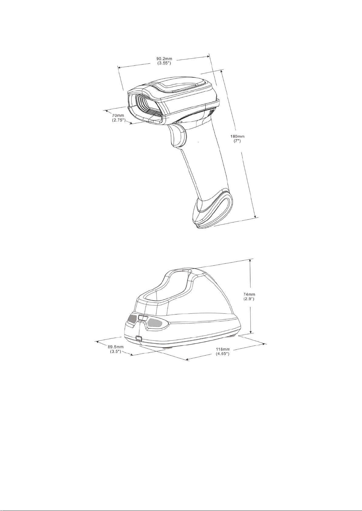
Dimensions Length × Width × Dept h: 90.2 × 70 × 180 mm
Weight
225 g
Color Gray
Indicator LED, Beeper, Vibrator
Operating Mode Handheld
Programming
Method
Manual (reading special b ar code)
Program Upgrade Using Flash Utility softw are, while a cradle unit is re quired.
Input Voltage 5 ± 0.25 VDC
Current 20 mA (st an dby), 350 mA (sc anning)
Battery 2600 mAh Lithium-ion battery
Charge Time 6 hours
Standby Time 6.5 days
Working Time 70 hours (1 scan per 5 seconds)
Image Size 1280 × 800 pixels
Field of View
Horizontal: 42°, vertical: 26.5°
Scanning Angle ±70°, ±75°, 360° (Ske w, Pitch, Roll)
Print Contrast 20% minim um reflectance difference
Decoding Capability
1D:
UPC-A, UPC-E, UPC-E1, EAN-13, EAN-
8, ISBN (Bookland EAN), ISSN,
Code 39, Code 39 full ASCII, Code 32, Trioptic Code 39, Interleaved 2 of 5,
Industrial 2 of 5, Matrix 2 of 5, Codabar (NW7), Code 128, UCC/EAN 128,
ISBT 128, Code 93, C ode 11 (USD-8), MSI/Pless ey, UK/Plessey, China Post,
China Finance, GS1 Dat aBar (formerly RSS) var ian ts
2D:
PDF417, MicroPDF417, QR code, DataMatr ix, Aztec Code
Minimum
Resolution
HD: 1D (Code 39): 3 mil, 2D (QR): 5 mil
SR: 1D (Code 39): 4 mil, 2D (PDF417): 6.7 mil
Decoding Depth
High desity series
(HD)
Standard range
series (SR)
3 mil Code39 (3 chars) 10 mm – 61 mm /
4 mil Code 128 (9 chars) 5 mm – 88 mm 55 mm – 106 mm
5 mil Code39 (3 chars) 0 mm – 108 mm 43 mm – 141 mm
10 mil Code39 (3 chars) 0 mm – 167 mm 0 mm – 310 mm
13 mil UPC (6 chars) 0 mm – 179 mm 0 mm – 335 mm
20 mil Code39 (1 char) 10 mm – 253 mm 8 mm – 480 mm
5 mil QR (40 chars) 7 mm – 65 mm /
6.7 mil PDF417 (20 chars) 0 mm – 105 mm 37 mm – 145 mm

2
10 mil QR (20 chars) 0 mm – 134 mm 0 mm – 168 mm
20 mil QR (20 chars) 0 mm – 215 mm 0 mm – 345 mm
Temperature
0° to 50°C (32° to 120°F), operating
-40° to 60°C (-40° to 140°F), storage
Humidity 5% to 95% (non-condensing)
Safety
EMC: EN55022, EN55024
Electrical Safety: EN60950-1
Photobiological Safety: EN62471:2008
Illumination: 0~100,00 0 LUX
Protection Class: IP51
Drop Resistance: Withst a nds mult ip le 1.5 m (5 ft.) drops to concrete
Note: Test condition: temperature at 27°C, sunny day, and visibility of 5 kilometers. Natural
surroundings significantly affect the communication distance in practice. The distance drops quickly in
the rainy, high-humidity, or heavy haze day; radio interference also shortens the communication
distance.
Cradle
Input Voltage 5 ± 0.25 VDC
Current 60 mA (wor king), 500 mA (charg ing)
Cable Straight 2.0 m (PS/2) / Straight 1.5 m (USB) / Straight 2.0 m (RS-232 )
Dimensions Length × Width × Dept h: 118 × 89.5 × 74 mm
Weight 140 g (witho ut cable)
Indicator LED
Programming
Method
Manual (reading special b ar code)
Program Upgrade PC online using Flash Utility software.
Temperature
0° to 50°C (32° to 120°F), operating
-40° to 60°C (-40° to 140°F), storage
Humidity 5% to 95% (non-condensing)
Drop Resistance Unit fun ctions normally after r epeated 1.5 m (5 ft.) dr ops to concrete

3
1-2 Default setting for each barcode
Code type
Read
enable
Check digit
verification
Check digit
transmission
Min. code
length
Proprietar
y
code ID
AIM
code ID
UPC-A √ √ √ (12)
2
A ]Em
UPC-E √ √ √ (8)
2
D ]Em
UPC-E1 √ √ √ (8)
2
D ]Em
EAN-13 √ √ √ (13)
2
A ]Em
EAN-8 √ √ √ (8)
2
C ]Em
ISBN (Bookland EAN)
/ ISSN
1
√ √ √ (13)
2
B ]Em
Code 39 √ - - 1 M ]Am
Interleaved 2 of 5 √ - - 6 I ]Im
Industrial 2 of 5 - - - 4 H ]Im
Matrix 2 of 5 √ - - 6 X ]Im
Codabar √ - - 4 N ]Fm
Code 128 √ √ - 1 K ]Cm
ISBT 128 √ √ - 1 K ]Cm
Code 93 √ √ - 1 L ]Gm
Code 11 - √ - 4 V -
MSI/Plessey - - - 4 O ]Mm
UK/Plessey - √ - 1 U ]Mm
UCC/EAN 12 8 √ √ - 1 K ]Cm
China Post √ - - (11)
2
T ]Im
China Finance √ - - (10)
2
Y -
GS1 DataBar √ - - (16)
2
R ]em
GS1 DataBar
3
√ - - (16)
2
R ]em
GS1 DataBar Limited √ - - (16)
2
R ]em
GS1 DataBar Expanded
√ - - 1 R ]em
PDF417 √ - - - - -
MicroPDF417 √ - - - - -
DataMatrix √ - - - - -
QR code √ - - - - -
Aztec Code √ - - - - -
Note:
1
The settings for ISBN/ISSN and EAN-13 must be t he same except the code ID.
2
Fixed-length barcodes.
3
The settings for GS1 Data Bar Tr uncated and GS1 Data Bar must be the same.
4
2 Get started
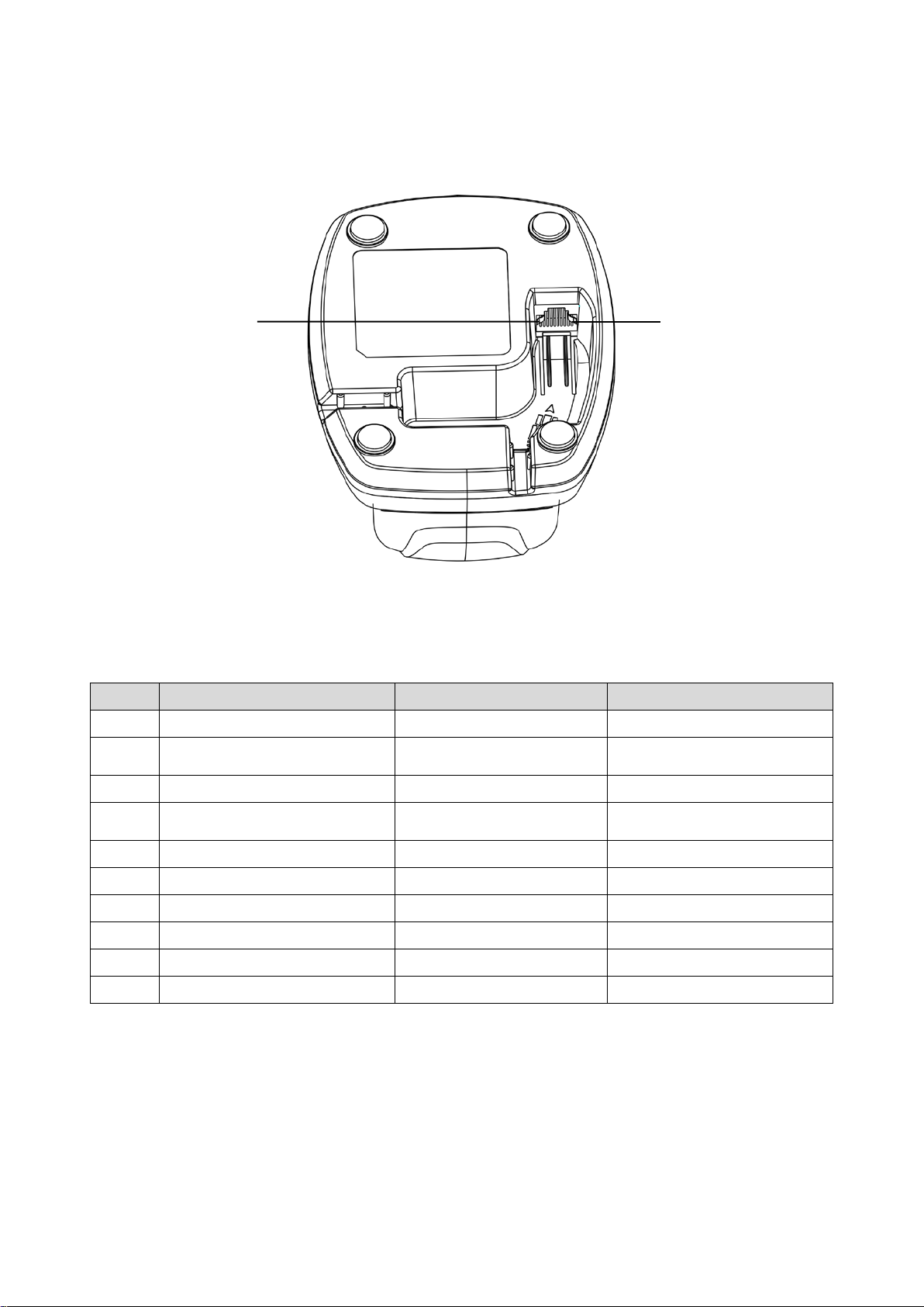
2-1 Cable connector pin-outs descriptions for c radle
Figure 2-1 Cable connector interface pin-outs
The pin-outs descriptions in Table 2-1 apply to the cable connector on the cradle and are for reference
only.
Table 2-1 Cable connector pin-outs descriptions
Pin
RS232
Keyboard (PS/2)
USB
1
Power (+5V)
Power (+5V)
Power (+5V)
2
+3.3V ( for interface auto
selection purpose)
Ground (for interface auto
selection purpose)
+3.3V ( for interface auto
selection purpose)
3
Ground
Ground
Ground
4
+3.3V ( for interface auto
selection purpose)
Reserved
Ground (for interface auto
selection purpose)
5
TxD
KeyClock
Reserved
6
RxD
KeyData
Reserved
7
Reserved
TermClock
Reserved
8
Reserved
TermData
Reserved
9
CTS
Reserved
D-
10
RTS
Reserved
D+
Note: V olt a ge lev el of al l RS23 2 Pin-outs (RxD, TxD, CTS and RTS) is 0V for logic low and 3. 3V for l ogic
high.
Pin 1 Pin 10
5
2-2 Dimensions
6
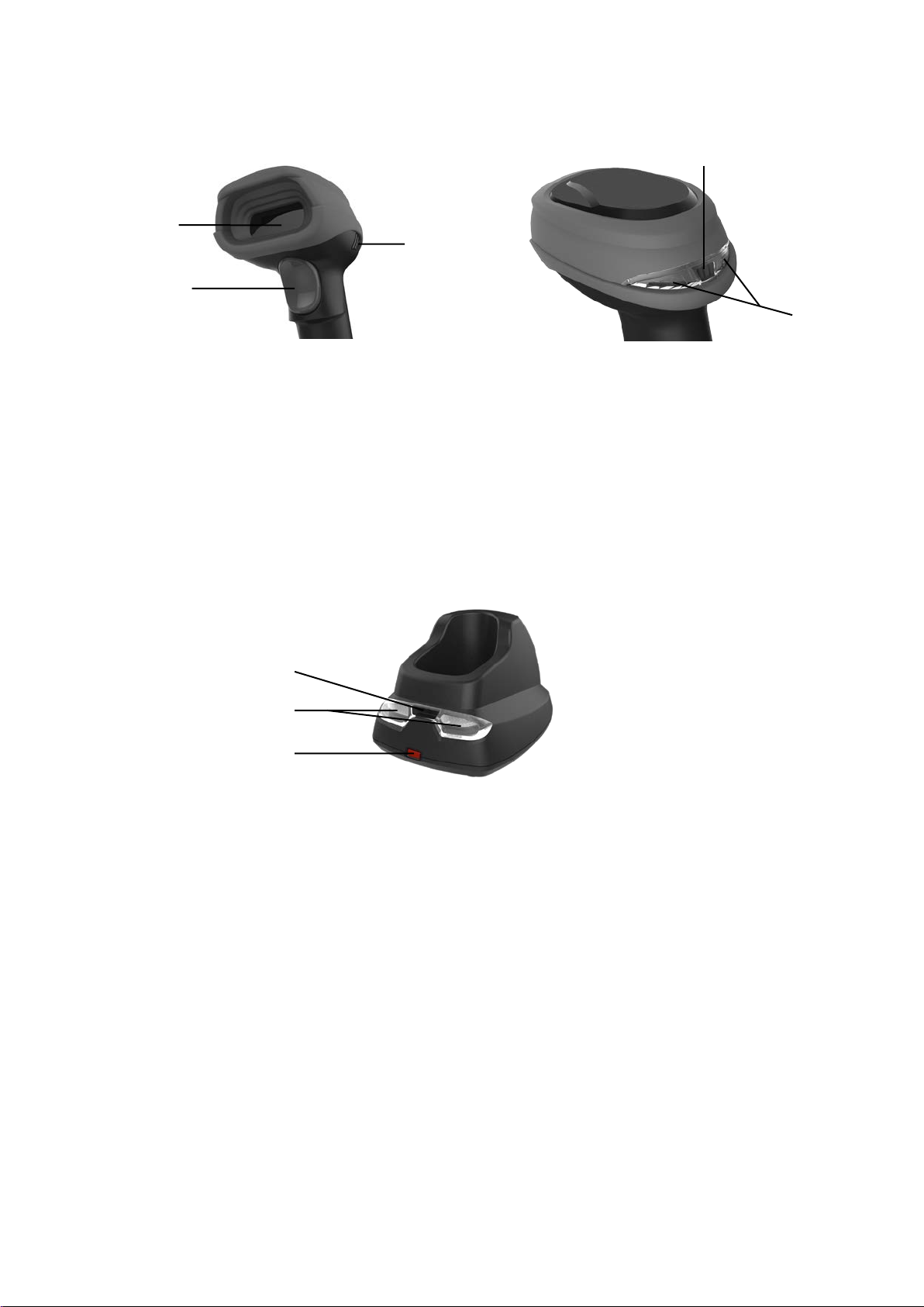
2-3 Parts of the scanner
Figure 2-2 Handheld unit
① Scan window
② Trigger (Press to triggr / Long press 3 seconds to turn on)
③ Beeper
④ On base indicator (Blue LED)
⑤ Successful decoding indicator (Green LED) / Communication fail indicator (Red LED) / Charging
indicator (Red/Green LED)
Figure 2-3 Cradle
⑥ Power indicator (Blue LED)
⑦ Communication indicator (Green LED)
⑧ Key (Long press 10 seconds to restore factory default setting of cradle)
①
②
③
⑤
④
⑥
⑦
⑧
7
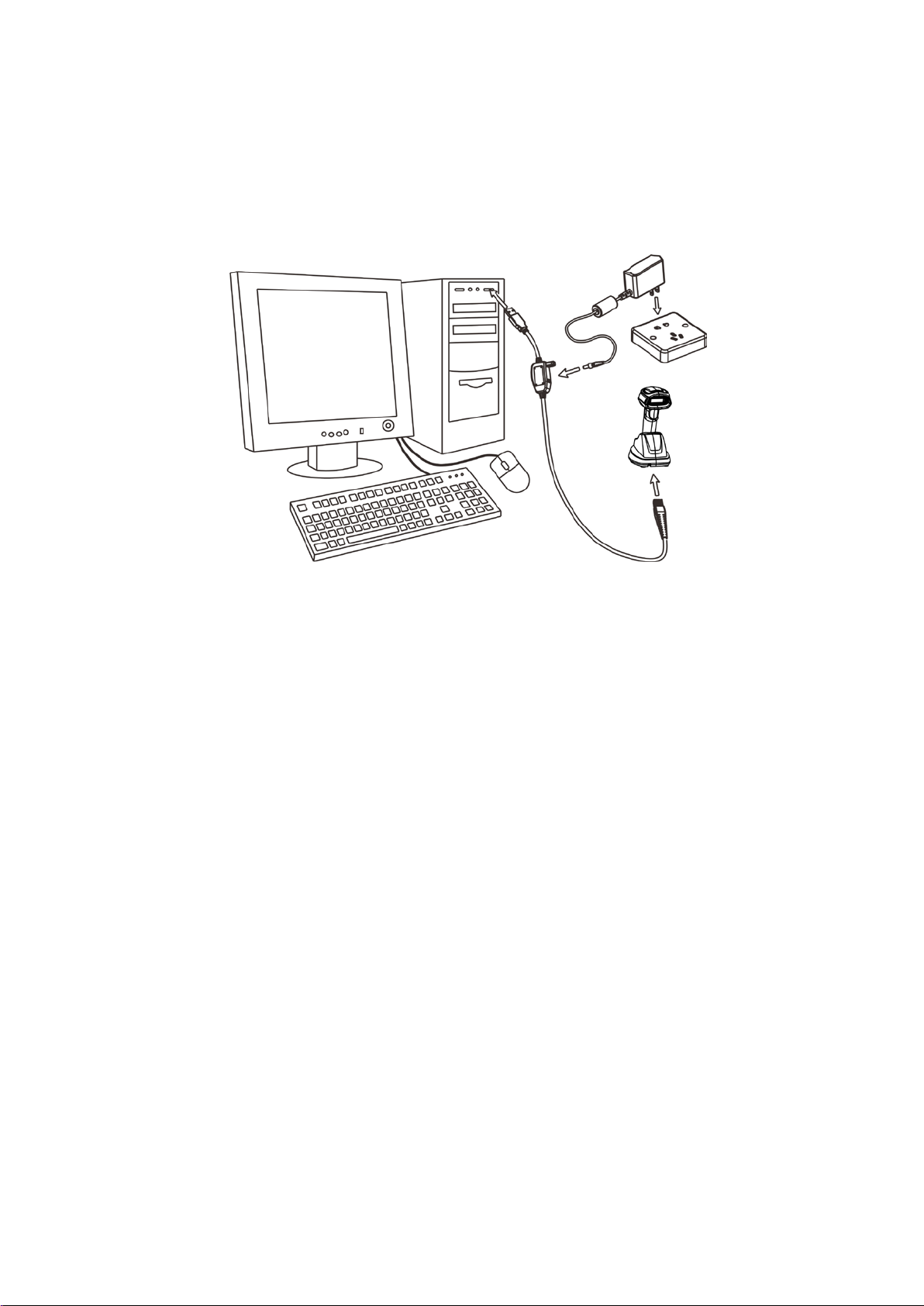
2-4 Charge battery
1. Please charge the battery before the first time of use. The charge indicator (red LED) on the
handheld unit is turned on when the charging is in proces s. When the charging proc ess co mplet es,
the red LED is turned of f.
2. Charging time: 6 hours for fully charged.
3. You can charge the battery via a USB port on the dev ice or a 5 VDC power adapter.
Note: The 5 VDC power adapter is an optional accessory.
Figure 2-4
8
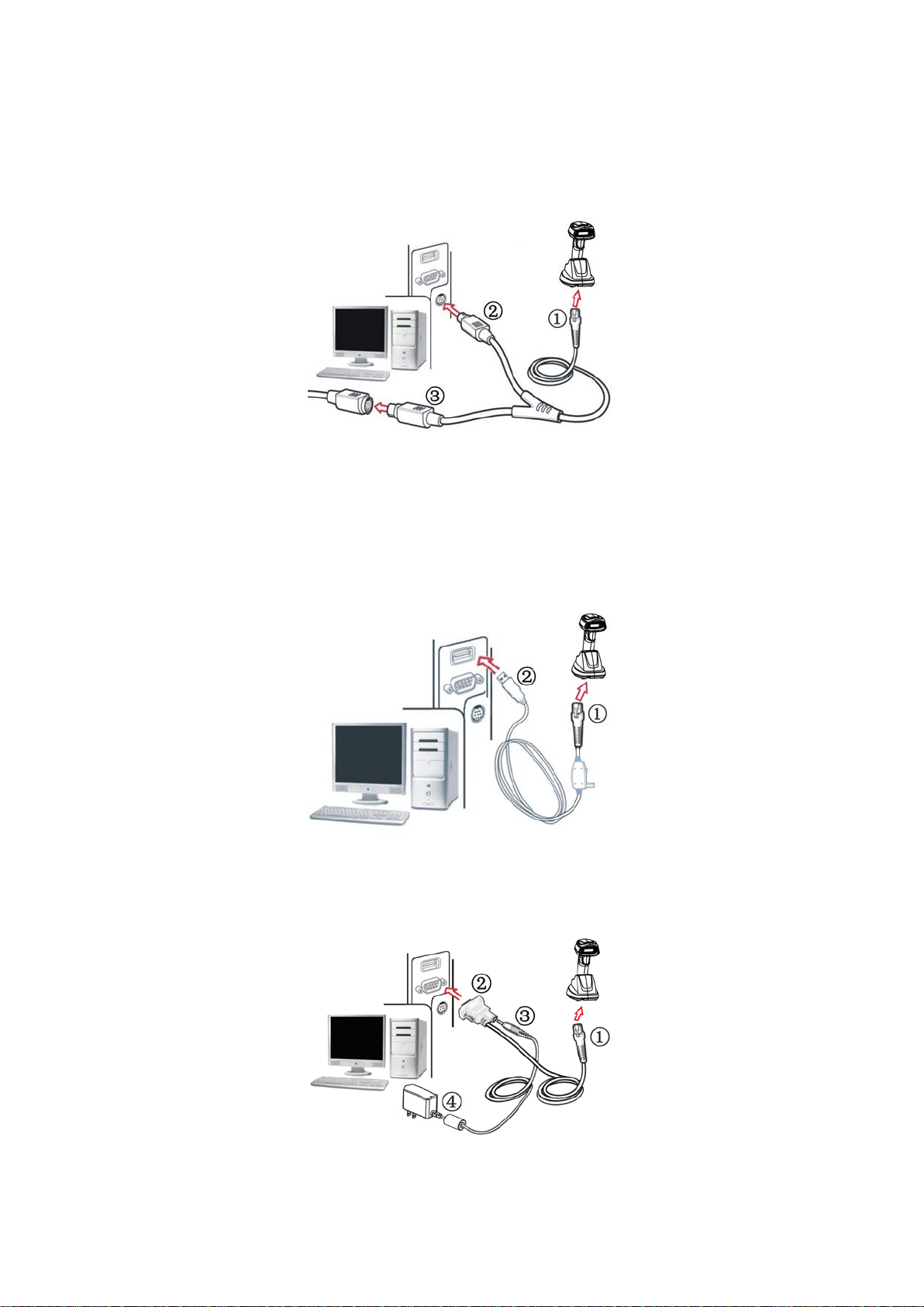
2-5 Installation of cradle
Note: If any of the below oper ation is in correct , t urn off the power immediately and che ck t he scan ner for
any improper connections. Go through all steps again.
2-5-1 PS/2 keyboard cable
Plug one end of the PS/2 keyboard cable to the cradle, one end to PS/2 port on PC, and one end to the
keyboard.
2-5-2 USB cable
1) Plug one end of the USB cable to the cr adle. Plug the other end into the USB port of the computer.
2) Wind ows giv es message on “new har dware found – USB HID input device found” , t hen driver will be
installed on request .
3) After successfully installing the new hardware, message will be given: “hardware installed
successfully and ready t o use”.
4) If any problem encounters during the installation process, please unplug the USB cable from the
computer and repeat step 1) and 2).
2-5-3 RS-232 cable
1) Connect the DB9 serial comm unication cable with the cradl e and t he COM port of the computer.
2) Plug the output of the AC/DC adaptor into the power terminal of on the cradle. Plug the AC/DC
adaptor provided by the manufacturer into an electr ical outlet.

9
3 Progamming menus
3-1 Example 1: Single-parameter setting by scanning 1D barcodes
Important notes:
1. During the process of programming, LED is lighting to indicate the programming correctness. LED
will go off if any incorrect programming operation performed.
2. After each success fu l programming, LED will go off and the scanner will bee p t wice.
3. Throughout the programming barcode menus, the factory default settings are indicated with
asterisks (*).
Two pr ogr amming modes have been prov ided as bellows:
❶ Single-scan setting
Scan the appropriate Single-scan setting (e.g. %0101D00%) acc or di ng t o the user‘s demand.
Example: To set Flow control to be XON/XOFF.
Steps: Scan the following barcode.
❷ Multiple-scan setting
Step 1. Scan the O pt ion barcode barcode (e.g. %0101M%) according to the user‘s demand.
Step 2. To the right of the option barcode, the necessary alphanumeric inputs are listed. Scan
two alphanumeric entries from 0 to 9 or A to F, refer to 10 Configuration alphanumeric entry
barcode.
Step 3. Repeat Step 2, i f more user parameters input are required.
Step 4. Scan the %END% barcode, listed on the lower left hand corner of each parameter
setting part.
Example: To set Flow control to be XON/XOFF.
Steps: Referring to 3-7 RS-232 interface for cradle, scan the following barcod es in order .
10
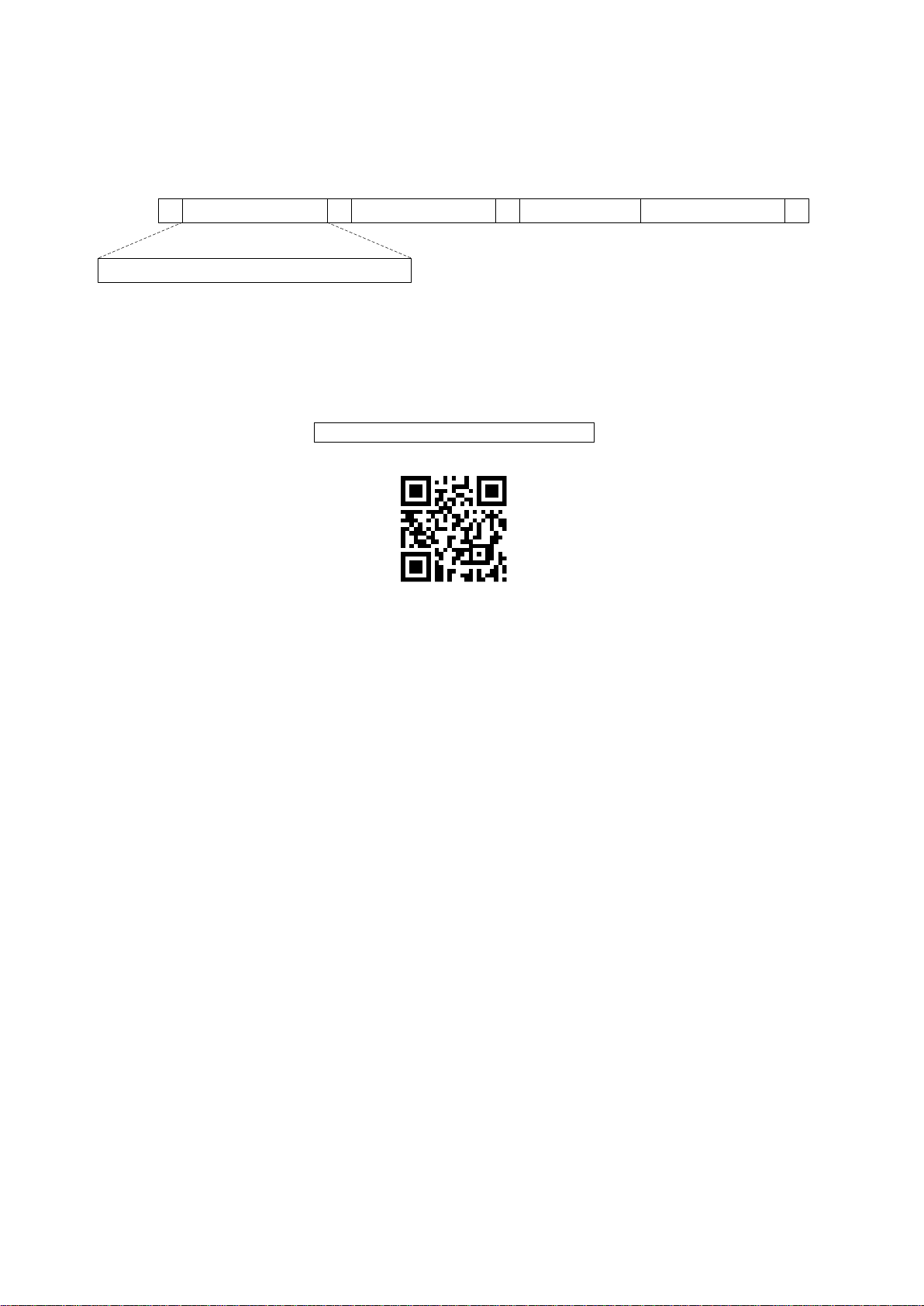
3-2 Example 2: Multiple-parameter setting by scanning a QR code
barcode
User can customize a QR code barcode to set multiple parameters. The scanner can set multiple
parameters by scanning this single QR code barcode.
1. The data format of the QR code barcode is as following.
% P aram eter set 1
%
Param eter set 2
% P aram eter set N %
<O ption barcode index><D /H ><A lpha. entries>
···
Note that:
<Option barcode index> means t he corresponding 4 digits of Option barcode.
<D/H> means “D” or “H” character . D means that the type of alphanumeric entry is dec imal; and H
means that the type of alphanumeric entry is hexadecimal.
<Alpha. entries> is a character string with various length of 2, 4, or other values.
Example: Set 0401->03 (decimal); 8002->0D0A (hexadecimal); 8202->01 (decimal). The customized
QR code barcode contents and symbol are as follo w ing.
%0401D03%8002H0D0A%8202D01%
2. Notes of making QR code barcode
The model is chosen as M2. Other requirements, e.g. ECC level, St art mode, etc, are not specif ied.
Other notes
1- The contents of a QR code barcode can include several same <Option barcode index> associated
with same or different <Alpha. entries>. In the case of with different <Alpha. entries>, the latest
<Alpha. entries> is the val id on e.
2- If any one of the parameter settings is invalid, the total setting is failed. The invalid setting can be
caused by one of the following problems: invalid <Option barcode index>, invalid type of <D/H>,
invalid type, length or value r ange of <Alpha. entries>, etc.

11
3-3 CS2290 Wireless communication setting
3-3-1 Wireless communication setting for handheld unit
Handheld unit RF channel No.: The scanner offers 16 different radio frequency channels for the data
transmission between handheld unit and cradle. The number of channel can be increased.
Multiple-scan setting
Single-scan setting
Option bar code
Option
Alpha. entry
Handheld unit RF channel No.
02-16
02-16
06*
*
12
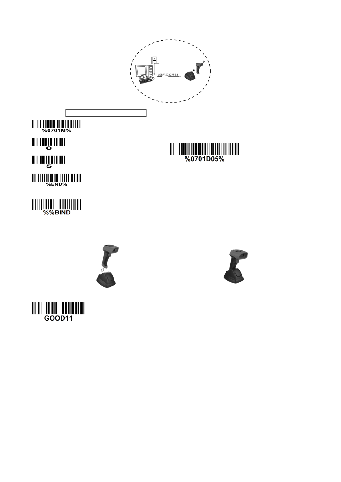
3-3-2 example
Example 1: One hand he ld unit and one cradle
The following takes channel No.5 for inst a nce.
Step 1): Set Handheld unit RF channel No. of the handheld unit to 5.
or
Step 2): Scan the following barcode t o bind the handheld unit with the cradle.
Firmly position the handheld unit onto the cradle. W ithin 10 seconds, two beeps will be emitted to
signal that the cradle has been paired to the handheld unit, and the blue LED on t he handheld unit will
go off. If three beeps are emitted, it indicates unsuccessful pairing between the cradle and the
handheld unit, then repeat step 2).
Test barcode:
13
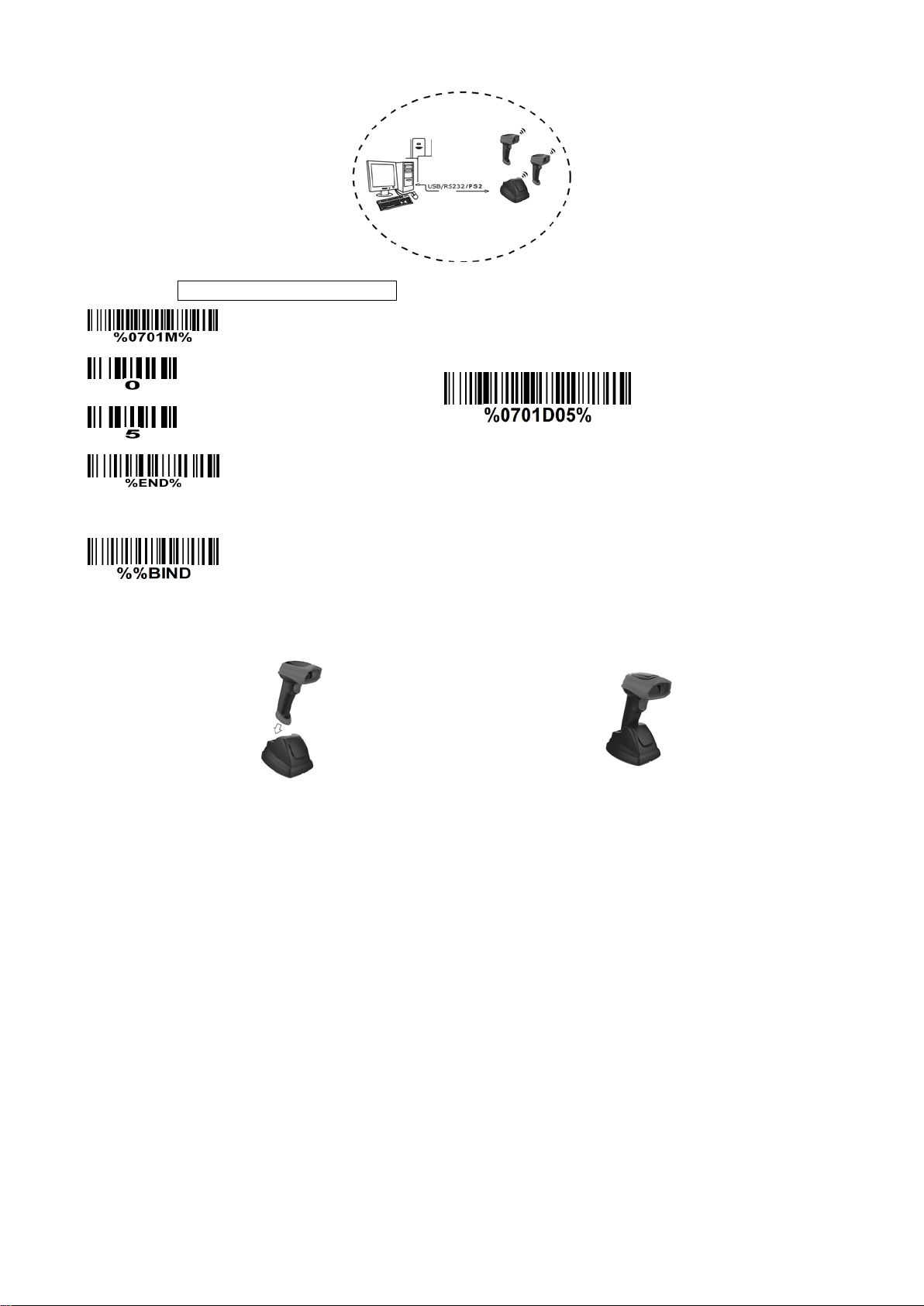
Example 2: Two handheld units and one cradle
The following takes channel No.5 for inst a nce.
Step 1): Set Handheld unit RF channel No. of the first handheld unit to 5.
or
Step 2): Make the first handheld unit scan the following barcode to bind the handheld unit with the
cradle.
Firmly position the handheld unit onto the cradle. W ithin 10 seconds, two beeps will be emitted to
signal that the cradle has been paired to the handheld unit, and the blue LED on t he handheld unit will
go off. If three beeps are emitted, it indicates unsuccessful pairing between the cradle and the
handheld unit, then repeat step 2).
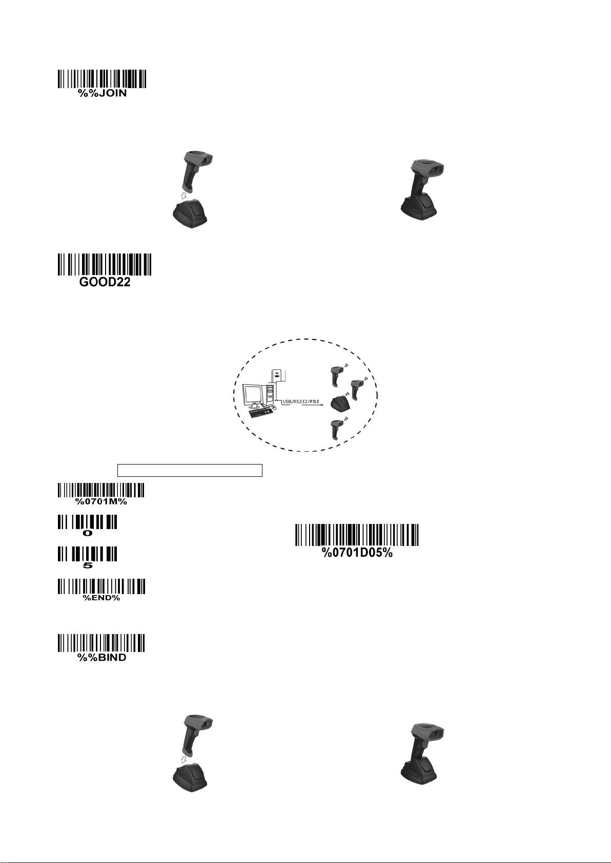
14
Step 3): Make the second huandhend unit scan %%JOIN barcode to pair the second handheld unit
with the cradle.
Firmly position the handheld unit onto the cradle. W ithin 10 seconds, two beeps will be emitted to
signal that the cradle has been paired to the handh eld unit, and the blue LED on t he handheld unit will
go off. If three beeps are emitted, it indicates unsuccessful pairing between the cradle and the
handheld unit, then repeat step 3).
Test barcode:
Example 3: Three handhel d uni ts and one cradle
The following takes channel No.5 for instance.
Step 1): Set Handheld unit RF channel No. of the first handheld unit to 5.
or
Step 2): Make the first handheld unit scan the following barcode to bind the handheld unit with the
cradle.
Firmly position the handheld unit onto the cradle. W ithin 10 seconds, two beeps will be emitted to
signal that the cradle has been paired to the handheld unit, and the blue LED on t he handheld unit will
go off. If three beeps are emitted, it indicates unsuccessful pairing between the cradle and the
handheld unit, then repeat step 2).
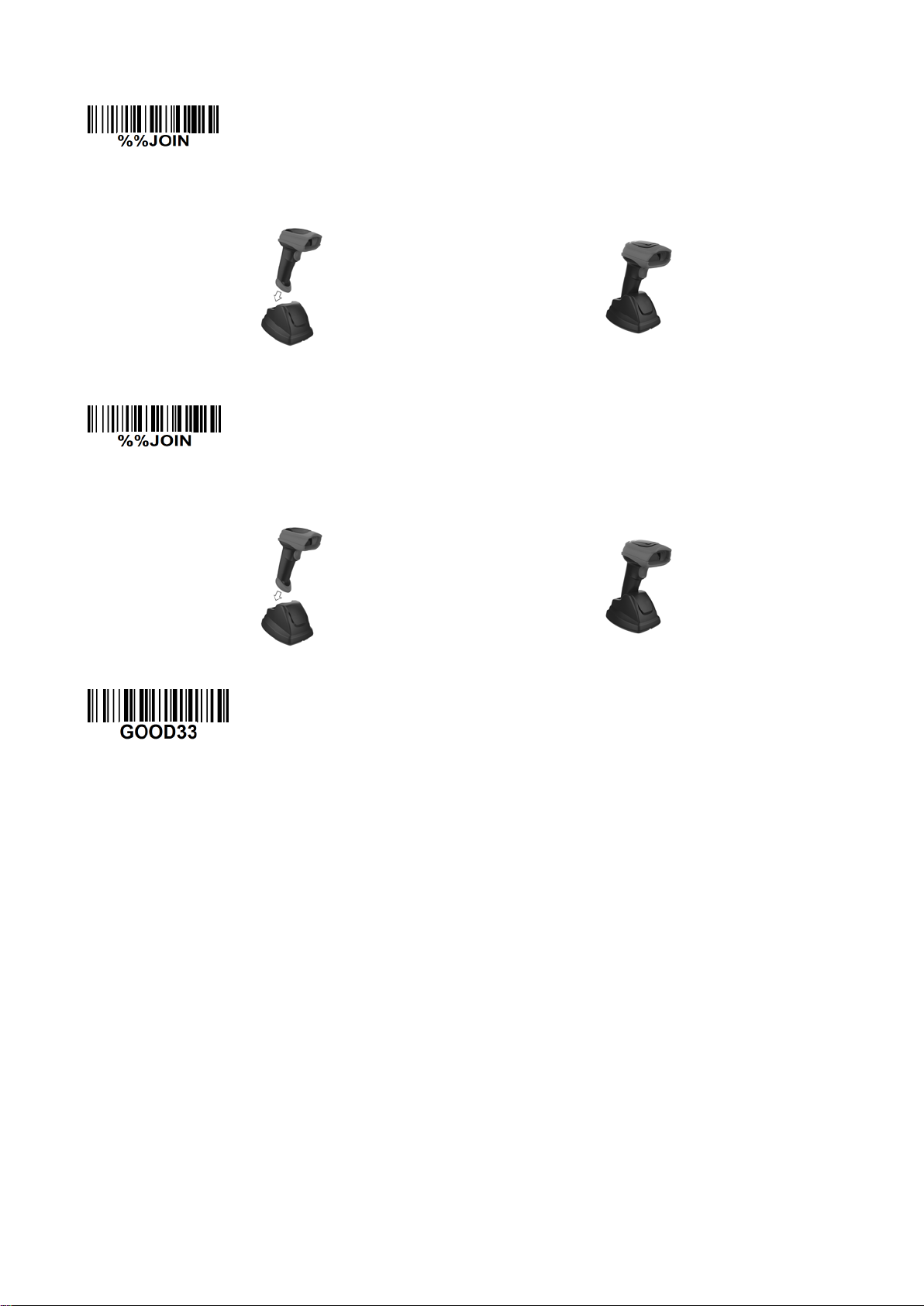
15
Step 3): Make the second huandhend unit scan %%JOIN barcode to pair the second handheld unit
with the cradle.
Firmly position the handheld unit onto the cradle. W ithin 10 seconds, two beeps will be emitted to
signal that the cradle has been paired to the handheld unit, and the blue LED on t he handheld unit will
go off. If three beeps are emitted, it indicates unsuccessful pairing between the cradle and the
handheld unit, then repeat step 3).
Step 4): Make the third huandhend unit scan %%JOIN barcode to pair the third handheld unit with the
cradle.
Firmly position the handheld unit onto the cradle. W ithin 10 seconds, two beeps will be emitted to
signal that the cradle has been paired to the handh eld unit, and the blue LED on the handheld unit will
go off. If three beeps are emitted, it indicates unsuccessful pairing between the cradle and the
handheld unit, then repeat step 4).
Test barcode:
16
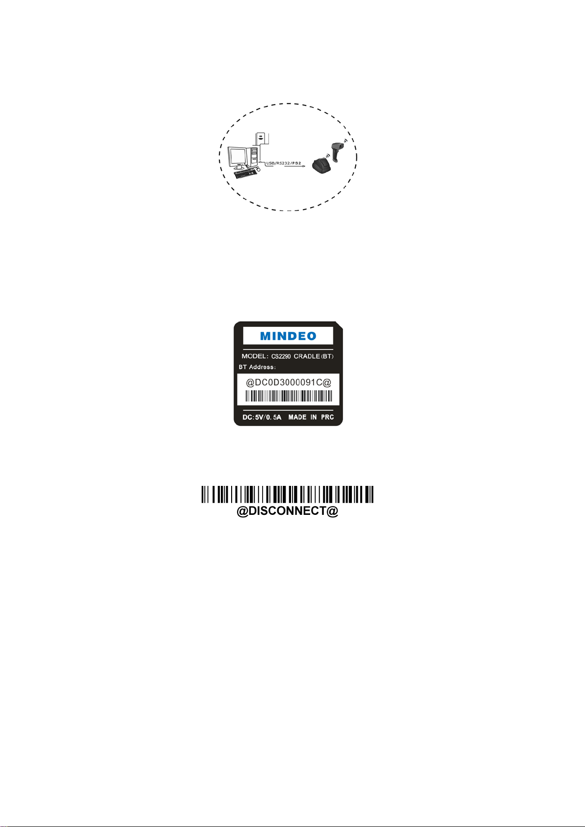
3-4 CS2290-BT Wireless communication setting
3-4-1 example
The handheld terminal shall ensure that the connection of the base and PC is successful before
communicating with the base.
Connect the base:
The handheld terminal scans t he c onnection barcode at the bottom of the base, and the handheld
terminal will attempt to co nnect to the base, at the same ti me ,t he handheld terminal will make a
beep-beep-beep sound.
If the connection is succ essful, t he handheld t erminal can be used d irect ly. If the
connection is unsuccessful, the handhe ld termina l will make a be ep—beep— sound, and t he red LED on
the handheld will blinks 2 times, and then turns off.
Disconnect:
The handheld terminal scan dis connect s the bar co de, and the han dheld ter minal can be disconnected
from the base
17
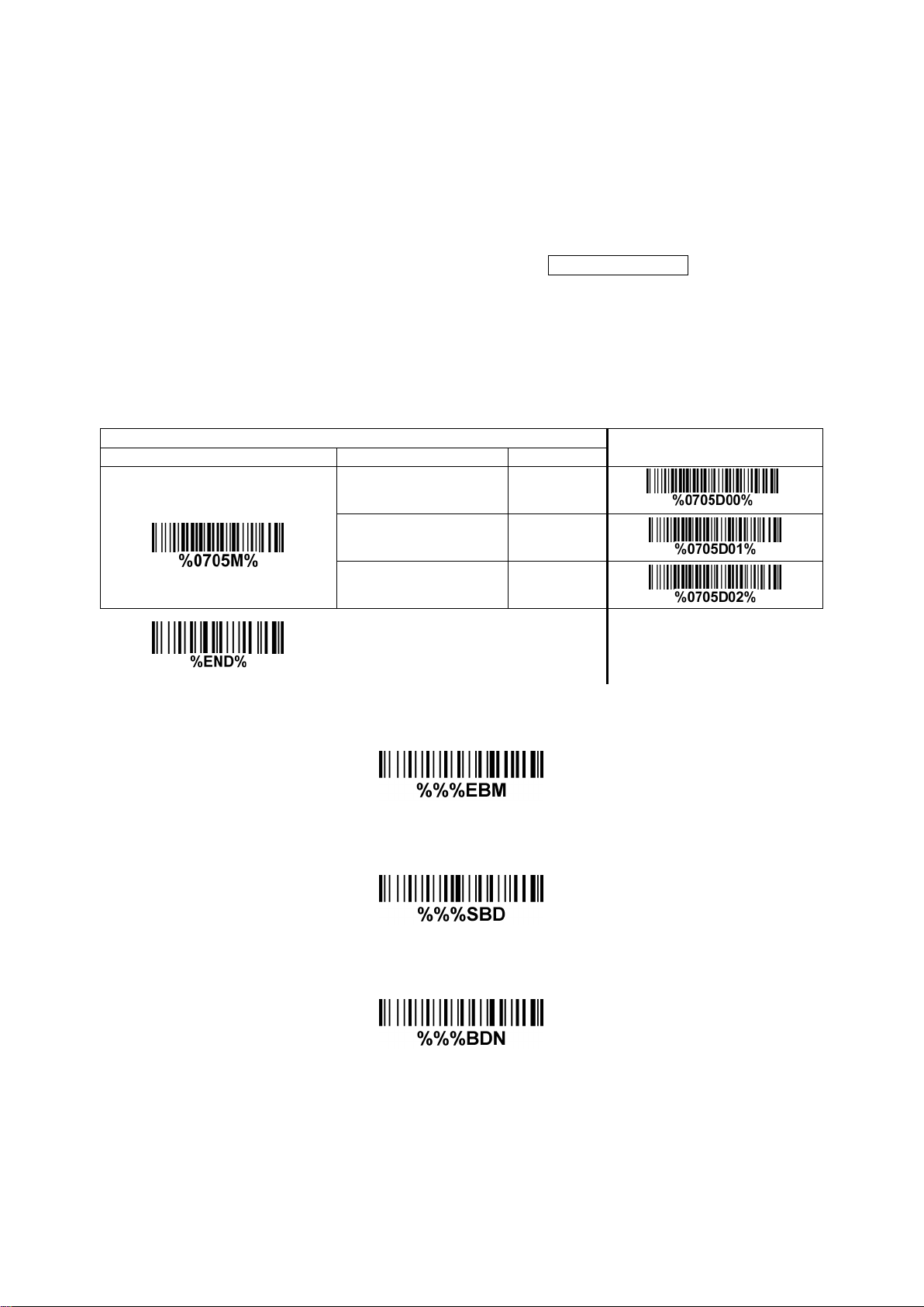
3-5 Batch data mode
Disable- Do not batch data. The handheld unit attempts to transmit every scanned barcode. If the
transmission is failed, the bar c ode data is ignored.
Out-of-range batch- The handheld un it starts stori ng barcode data when it loses its co nnection to a
remote device (for example, when a user holding the handheld unit walks out of range). Data
transmission is triggered by reestablishing the connection with the cradle (for example, when a user
holding the handheld unit w alks back into range).
Standard batch- The handheld unit starts storing barcode data after %%%EBM” (Enter Batch Mode)
is scanned. Data transmission is triggered by scanning “%%%SBD” (Send Batch Data).
If you wish to output the total number of barcodes scanned when in Standard batch Mode, scan“%%%BDN”.
In Out-of-range batch or Standard batch modes, calculate the number of barcodes the handheld unit
can store as follows:
Number of storable barcodes = 524,288 bytes of m em or y / (number of characters in t he barcode + 2).
Multiple-scan setting
Single-scan setting
Option bar code
Option
Alpha. entry
Batch data mode
Disable 00*
*
Out-of-range batch 01
Standar d bat ch 02
Enter batch mode
Send batch data
Total Records

18
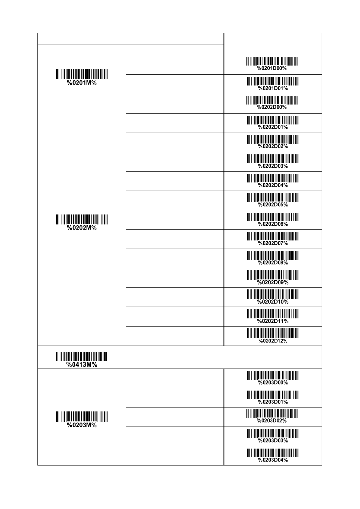
3-6 Keyboard wedge interfac e for c ra dle
Keyboard type: As a keyboard interface, the scanner supports most of the popular PCs and IBM
terminals.
Keyboard layout: The scanner supports different national keyboard layouts.
Clock period: According to the PS2 protocol, the clock is provided by the device, e.g. keyboard or
scanner, with the period betw een 60us to 100us.
Delay-after-compound-key: In some rare occa sions, machine with low speed PS2 communication port
would require a free time gap f ol lowing the press/release of the compound key (Shift, Ctrl or Alt).
Numeric key:
Alphabetic key- The scanner will output code result as alphabetic key.
Numeric key- The scanner will output code result as pressing numeric keypad ( ‘0’, ‘1’, ‘2’, ‘3’, ‘4’, ‘5’,
‘6’, ‘7’, ‘8’, ‘9’, ‘.’, ‘+’, ‘-‘, ‘/’, ‘*’ only).
Alt + keypad- The scanner will output code result as pressing Alt+ numeric key (on keypad). Note
that the Num Lock control key must be ON. This setting can be specially adapted for use with
different nationa l keyboard layout.
Power-on simulation: All of the PCs check the keyboard status during power-on self test. It simulates
keyboard timing and p asses keyboard present status to the PC during pow er-on.
Inter-character delay: This delay is inserted after each data character t r ansmitted.
Inter-byte delay: This delay is inserted after each byte transmitted. Normally a character is compr ised
of three or above bytes.
Block tr ans. delay: It is a delay timer between barcode data output. This feature is used to transfer
continually with shorter ba r code data.
Caps Lock reversion: By set ting enable, t he st atus of Caps Lo ck key (i. e. being pr essed O N or OFF) on
the keyboard is simulated in a reversion status.
Caps Lock override: If this functi on i s enabled, on AT or AT notebook hosts, the keyboard ignores the
state of the Caps Lo ck key. Therefore, an ‘A’ in t he bar code is sent as an ‘A’ no matter what the st ate of
the keyboard’s Caps Lock key.
A guide of setting while t he sca nned data is incorrect ly displayed on the host
If some characters are missed or some additional characters are incorrectly displayed on the host,
set the Inter-byte delay (0208) to be “01” or greater value.
If some capital c haracter ( e.g. “A”) or compo und-key-characters (e.g.“shift+”, “Ctrl+”, “Alt+”)are
displayed incorrectly, set the Delay-after-compound-key to be “01” or greater value.
If some digits are incorrectly displayed as some symbol characters (e.g. “1” and “2” are displayed
incorrectly as “!” and “@”), set the Clock period (0203) to be greater value (e.g. 04, 05).
19
Multiple-scan setting
Single-scan setting
Option bar code Option Alpha. entry
Keyboard type
IBM A T, PS/2 00*
*
Apple Mac
compatibles
01
Keyboard layout
USA 00*
*
Turkish F 01
Turkish Q 02
French 03
Italian 04
Spanish 05
Slovak 06
Denmark 07
Japanese 08
German 09
Belgian 10
Russian 11
Czech 12
Character encoding system
Refer to 3-9 Handheld scan & some global settings.
Clock period
60 us 00
70 us 01
80 us 02*
*
90 us 03
100 us 04

20
Multiple-scan setting
Single-scan setting
Option bar code Option Alpha. entry
200 us 05
Delay-after-compound-key
0 ms 00*
*
10 ms 01
20 ms 02
40 ms 03
80 ms 04
Numeric key
Alphabetic key 00*
*
Numeric keypad 01
Alt + keypad 02
Power-on simulation
Disable 00*
*
Enable 01
Inter-character delay
0 ms 00*
*
5 ms 01
10 ms 02
20 ms 03
40 ms 04
80 ms 05
Inter-byte delay
1 ms 00*
*
2 ms 01
4 ms 02
8 ms 03
Caps Lock reversion Disable 00*
*
Loading...