

Minarik Drives LV Series Users Manual

USER’S MANUAL
LV Series
Low Voltage Input, Pulse-Width Modulated,
Adjustable Speed Drives
for DC Brush Motors
Models: LV01-24AC-E10U
LV02-24AC
LV02-24DC

Copyright © 2013 by
Minarik Drives
All rights reserved. No part of this manual may be reproduced or transmitted in any
form without written permission from Minarik Drives. The information and technical
data in this manual are subject to change without notice. Minarik Drives makes no
warranty of any kind with respect to this material, including, but not limited to, the
implied warranties of its merchantability and fitness for a given purpose. Minarik
Drives assumes no responsibility for any errors that may appear in this manual and
makes no commitment to update or to keep current the information in this manual.
Printed in the United States of America.

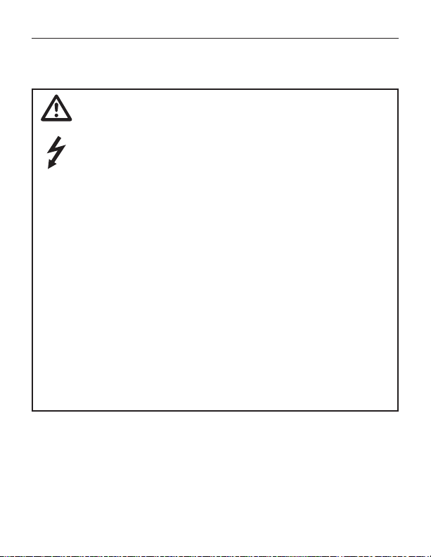
Safety Warnings
Throughout this manual, this symbol denotes an
important safety tip. Read these sections very carefully!
• Have a qualified electrical maintenance technician install,
adjust and service this equipment. Follow the National
Electrical Code and all other applicable electrical and safety
codes, including the provisions of the Occupational Safety
and Health Act (OSHA), when installing equipment.
• Reduce the chance of an electrical fire, shock, or explosion by
proper grounding, over-current protection, thermal protection,
and enclosure. Follow sound maintenance procedures.
• It is possible for a drive to run at full speed as a result of a
component failure. To stop the drive in an emergency, ensure
that a master switch has been installed in the AC line.
• This drive is not isolated from earth ground. Circuit
potentials of up to 115 VAC exist on the board.Direct contact
with the printed circuit board or with circuit elements poses the
risk of serious injury or fatality. Use a non-metallic screwdriver
for adjusting the calibration trimpots
i

ii
Contents
Mounting . . . . . . . . . . . . . . . . . . . . . . . . . . . . . . . . . . . . . . . . . . . . . . . . . . . . .4
Line Fusing . . . . . . . . . . . . . . . . . . . . . . . . . . . . . . . . . . . . . . . . . . . . . . . . . . .5
Shielding guidelines . . . . . . . . . . . . . . . . . . . . . . . . . . . . . . . . . . . . . . . . . . . .6
Speed adjust potentiometer installation . . . . . . . . . . . . . . . . . . . . . . . . . . . . .7
Connections (LV series) . . . . . . . . . . . . . . . . . . . . . . . . . . . . . . . . . . . . . . . . .8
Connections (LV-E10U series) . . . . . . . . . . . . . . . . . . . . . . . . . . . . . . . . . . .10
Voltage follower (LV series) . . . . . . . . . . . . . . . . . . . . . . . . . . . . . . . . . . . . . .11
Voltage follower (LV-E10U series) . . . . . . . . . . . . . . . . . . . . . . . . . . . . . . . . .12
Startup . . . . . . . . . . . . . . . . . . . . . . . . . . . . . . . . . . . . . . . . . . . . . . . . . . . . . .13
Line starting and stopping . . . . . . . . . . . . . . . . . . . . . . . . . . . . . . . . . . . . . .14
Decelerating to a stop . . . . . . . . . . . . . . . . . . . . . . . . . . . . . . . . . . . . . . . . .14
Dynamic braking . . . . . . . . . . . . . . . . . . . . . . . . . . . . . . . . . . . . . . . . . . . . . .15
MINIMUM SPEED (MIN SPD) . . . . . . . . . . . . . . . . . . . . . . . . . . . . . . . . . . .18
MAXIMUM SPEED (MAX SPD) . . . . . . . . . . . . . . . . . . . . . . . . . . . . . . . . . .18
TORQUE LIMIT (TQ LIMIT) . . . . . . . . . . . . . . . . . . . . . . . . . . . . . . . . . . . . .19
IR COMPENSATION (IR COMP) . . . . . . . . . . . . . . . . . . . . . . . . . . . . . . . . .20
i sgninraW ytefaS
1 snoitacificepS
2snoisnemiD
4 noitallatsnI
5gniriW
31noitarepO
31rewop gniylppa erofeB
61 noitarbilaC

Multiple fixed speeds . . . . . . . . . . . . . . . . . . . . . . . . . . . . . . . . . . . . . . . . . .21
Adjustable speeds using potentiometers in series . . . . . . . . . . . . . . . . . . . .22
Independent adjustable speeds . . . . . . . . . . . . . . . . . . . . . . . . . . . . . . . . . .23
RUN/JOG switch . . . . . . . . . . . . . . . . . . . . . . . . . . . . . . . . . . . . . . . . . . . . .24
Reversing . . . . . . . . . . . . . . . . . . . . . . . . . . . . . . . . . . . . . . . . . . . . . . . . . . .25
Before troubleshooting . . . . . . . . . . . . . . . . . . . . . . . . . . . . . . . . . . . . . . . . .26
Replacement Parts . . . . . . . . . . . . . . . . . . . . . . . . . . . . . . . . . . . . . . . . . . . .29
iii
12 setoN noitacilppA
62gnitoohselbuorT
revoc kcab edisni ytnarraW detimiL

iv
Illustrations
Figure 1. LV Series Dimensions . . . . . . . . . . . . . . . . . . . . . . . . . . . . . . . . . . . . . . .2
Figure 2. LV-E10U Series Dimensions . . . . . . . . . . . . . . . . . . . . . . . . . . . . . . . . . .3
Figure 3. Speed Adjust Potentiometer . . . . . . . . . . . . . . . . . . . . . . . . . . . . . . . . . . .7
Figure 4. LV Series Line Input and Speed Potentiometer Connections . . . . . . . . .8
Figure 5. LV Series Motor Connections . . . . . . . . . . . . . . . . . . . . . . . . . . . . . . . . .9
Figure 6. LV-E10U Series Drive Connections . . . . . . . . . . . . . . . . . . . . . . . . . . . .10
Figure 7. LV Series Voltage Follower Connections . . . . . . . . . . . . . . . . . . . . . . . .11
Figure 8. LV-E10U Voltage Follower Connections . . . . . . . . . . . . . . . . . . . . . . . .12
Figure 9. Run/Decelerate to Zero Speed Switch . . . . . . . . . . . . . . . . . . . . . . . . . .14
Figure 10. Dynamic Brake Connection . . . . . . . . . . . . . . . . . . . . . . . . . . . . . . . . .15
Figure 11. LV SERIES Calibration Trimpot Layout . . . . . . . . . . . . . . . . . . . . . . . .16
Figure 12. LV-E10U SERIES Calibration Trimpot Layout . . . . . . . . . . . . . . . . . . .17
Figure 13. Multiple Fixed Speeds . . . . . . . . . . . . . . . . . . . . . . . . . . . . . . . . . . . . .21
Figure 14. Adjustable Fixed Speeds Using Potentiometers in Series . . . . . . . . . .22
Figure 15. Independent Adjustable Speeds . . . . . . . . . . . . . . . . . . . . . . . . . . . . . .23
Figure 16. RUN/JOG Switch Connection to Speed Adjust Potentiometer . . . . . .24
Figure 17. Reversing Circuit Connection . . . . . . . . . . . . . . . . . . . . . . . . . . . . . . .25

Specifications
1
Maximum
Model Voltage (Amps DC) Range** Range
LV01–24AC-E10U 8–24 VAC* 1.0 0–22 VDC 1/500–1/100
LV02–24AC 8–24 VAC* 2.0 0–22 VDC 1/250–1/50
LV02–24DC 10–36 VDC 2.0 0–22 VDC 1/250–1/50
** AC input voltage is ±10%, 50/60 Hz, single phase
** Maximum output voltage is 91% of input voltage. Rating shown is with 24V input.
Form Factor 1.05 at base speed
Acceleration Time 1 second
Deceleration Time 1 second
Load Regulation (at base speed) 2%
Ambient Temp. Range 10°C–40°C
Vibration 0.5g max (0 – 50 Hz)
Analog Input Voltage Range (S1 to S2) 0-4.6 VDC
Input Current Voltage HP
Armature Armature
0.1g max (above 50 Hz)
2
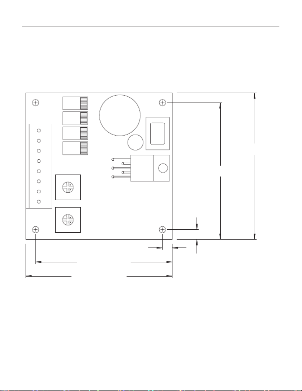
Dimensions
D5 0 5
D5 0 4
AC 1 AC 2 A 2 S3 S 2 S 1A1
C 5 0 1
D5 0 3
C 5 0 2
D5 0 2
VFB INGND
COMP
OUT
D5 0 1
M IN SP DM A X S P D
0.150" [4]
2.100 [53]
2.100" [53]
2.250 [57]
2.250" [57]
0.150 [4]
IC 5 0 1
R5 0 1
0.150 [4]
0.150" [4]
2.100 [53]
2.100" [53]
2.250 [57]
2.250" [57]
ALL DIMENSIONS IN INCHES [MILLIMETERS]
Figure 1. LV01 Series Dimensions
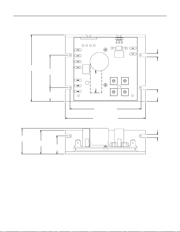
Dimensions
3
1.40 [36]
1.40 [36]
BR 50 1
+ ~ ~ -
3.58 [91]
3.58 [91]
1.28 [33]
1.28 [33]
1.75 [44]
1.75 [44]
0.74 [19]
0.74 [19]
0.97 [25]
0.97 [25]
L1
L2
DC + IN
DC - IN
S1
S2
S3
C5 01
R50 2
(ALTERNATE)
C5 03
C501
3.80 [97]
3.80 [97]
4.30 [109]
4.30 [109]
ALL DIMENSIONS IN INCHES [MILLIMETERS]
Figure 2. LV02 Series Dimensions
MIN S PD
MA X SP D
IC5 01
D50 1
A1
A2
R50 1
IR CO M P
C5 02
TQ LI MIT
0.19 [5]
0.19 [5]
0.64 [16]
0.64 [16]
0.19 [5]
0.19 [5]

4
Installation
Do not install, rewire, or remove this control with input
power applied. Doing so may cause fire or serious injury.
Make sure you have read and understood the Safety
Warnings on pg i before attempting installation.
Mounting
Drive components are sensitive to electrostatic fields. Avoid
•
direct contact with the circuit board. Hold drive by the chassis
only.
Protect the drive from dirt, moisture, and accidental contact.
•
Provide sufficient room for access to the terminal block and
calibration trimpots.
Mount the drive away from heat sources. Operate the drive
•
within the specified ambient operating temperature range.
Prevent loose connections by avoiding excessive vibration of
•
the drive.
Mount drive with its board in either a horizontal or vertical
•
plane. Six 0.19 in. (5 mm) wide slots in the chassis accept #8
pan head screws. Fasten either the large base or the narrow
flange of the chassis to the subplate.*
The chassis must be earth grounded. Use a star washer beneath
•
the head of at least one of the mounting screws to penetrate the
anodized chassis surface and to reach bare metal.
*Does not apply to LV01-24AC/DC-E10U
Wiring
Warning
Do not install, remove, or rewire this equipment with power
applied. Failure to heed this warning may result in fire,
explosion, or serious injury.
Circuit potentials are at 115 or 230 VAC above ground. To
prevent the risk of injury or fatality, avoid direct contact
with the printed circuit board or with circuit elements.
Do not disconnect any of the motor leads from the drive
unless power is removed or the drive is disabled. Opening
any one motor lead may destroy the drive.
This product does not have internal solid state motor overload
protection. It does not contain speed-sensitive overload
protection, thermal memory retention or provisions to receive
and act upon signals from remote devices for over temperature
protection. If motor overload protection is needed in the enduse product, it needs to be provided by additional equipment
in accordance with NEC standards.
Installation
5
Line Fusing
Protect all Minarik Drives’s drives with a line fuse. Use fast acting
fuses rated for 250 volts, 3 amps.
For LV01/02-24AC drives, fuse only the hot side of the AC line (L1).
••
For LV01/02-24DC drives, fuse the DC+ IN side of the DC voltage input.

6
Installation
Shielding guidelines
Warning
Under no circumstances should power and logic leads be
bundled together. Induced voltage can cause unpredictable
behavior in any electronic device, including motor controls.
As a general rule, Minarik Drives recommends shielding of all
conductors.
If it is not practical to shield power conductors, Minarik Drives
recommends shielding all logic-level leads. If shielding logic
level leads is not practical, the user should twist all logic leads
with themselves to minimize induced noise.
It may be necessary to earth ground the shielded cable. If noise is
produced by devices other than the drive, ground the shield at the
drive end. If noise is generated by a device on the drive, ground
the shield at the end away from the drive. Do not ground both
ends of the shield.
If the drive continues to pick up noise after grounding the shield,
it may be necessary to add AC line filtering devices, or to mount
the drive in a less noisy environment.
Logic wires from other input devices, such as motion controllers
and PLL velocity controllers, must be separated from power lines
in the same manner as the logic I/O on this drivedrive.
 Loading...