

Minarik Drives HTL05-D-4Q-L Quick Start Guide
4.818 [122.38]
5.630 [143.00]
0.250 [6.35]
1
6
1
9
8
FWD
SPEED
REV
SPEED
FWD
CURR
REV
CURR
ERROR
GAIN
FB
GAIN
FB
OFFSET
- BUS
+ BUS
A1
A2
J503
J504
J505
J502
24V 12V
L1
L2
230
VAC
115
VAC
6.130 [155.70]
2.00 [50.80]
5.630 [143.00]
1.48 [37.59]
2.45 [62.23]
0.750 [19.05]
1.618 [41.10]
ALL DIMENSIONS IN INCHES [ MILLIMETERS]
1
2
3
1
2
3
1
2
3
J501
CURR LIMIT
POWER
1
6
1
9
8
FWD
SPEED
REV
SPEED
FWD
CURR
REV
CURR
ERROR
GAIN
FB
GAIN
FB
OFFSET
1
2
3
1
2
3
1
2
3
+
BUS
-
BUS
A1
A2
J503
J504
J505
J502
L1
L2
J501
24V 12V
LINE VOLTAGE
INPUT
115/230
VAC
1 (+5)
12 or 24
VDC
230 VAC
115
VAC
POWER
CURR LIMIT
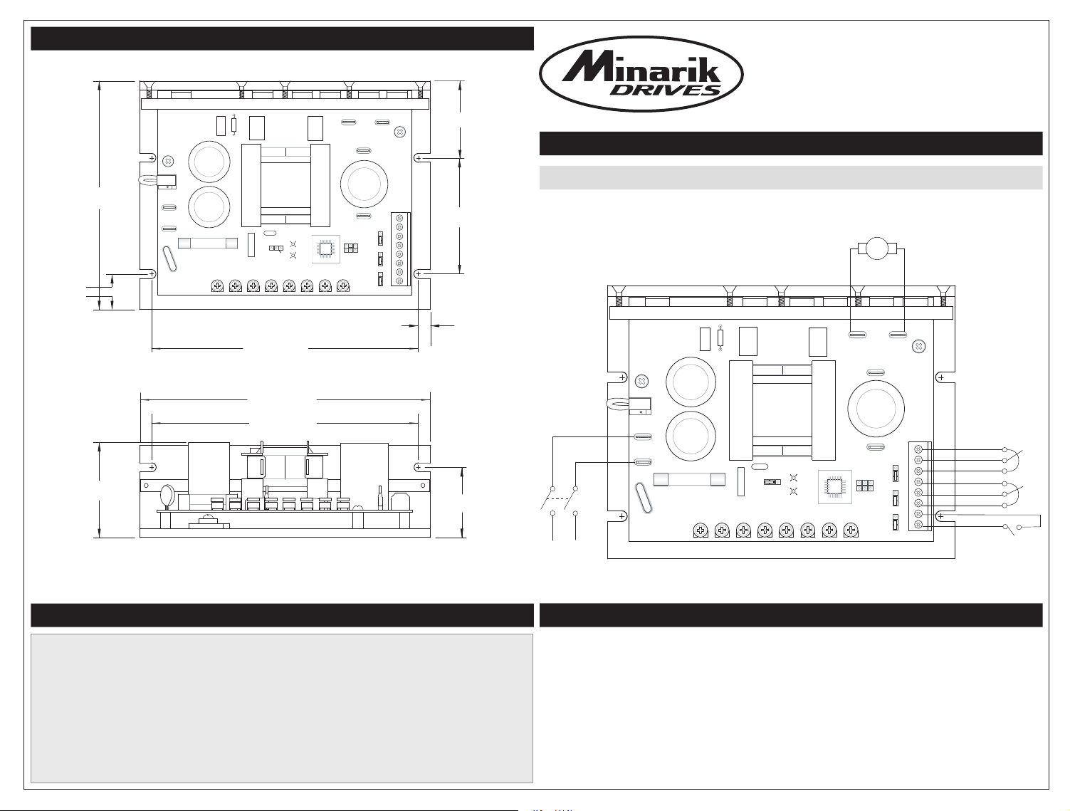
D I M E N S I O N S
HTL05-D-4Q-L
High to Low Voltage Four Quadrant DC Drive
With Linear Potentiometer Feedback
Q U I C K S TA R T G U I D E
C O N N E C T I O N S
2 (CMD)
COM)
3 (
4 (+5)
5 (FB)
6 (COM)
7 (INH)
COM)
8 (
In p ut Vol t age + /- 1 0 % 5 0 /60 H z (VA C ) 115 / 230
Ou t put Vo l tage (VD C ) 0- 1 2 or 0-24
10 Seco n d Ou t put C urr e nt ( A mps) 7. 5
Sp e ed R a nge 80 : 1
Sp e ed R e gula t ion 1%
Fo r m Fa c tor 1. 0 5
Am b ient Tem pera t ure ( °C) 10 - 40
S P E C I F I C AT I O N S
5Co n tinu o us O u tpu t Cur r ent ( Amps )
D E S C R I P T I O N
The HTL05-D-4Q-L drive is designed specifically for positioning applications that send a position
feedback voltage signal back to the drive to create a closed loop system. The most common
application for this drive is a linear actuator with a built-in potentiometer for position feedback. The
drive can also accept an analog voltage signal proportional to position from a sensor for feedback.
The position command signal can come from a potentiometer, 0-5 VDC, or 0-10 VDC signal from
a PLC. The drive inputs are isolated from the line.

J501
J502
J503
J504
J505
230 VAC
115 VAC
24 V 12 V
10 V
5 V
INVERT
NORMAL
1
2
3
1 2 3
1
2
3
1
2
3
1
2
3
S T E P O N E : S E T J U M P E R S
S T E P T H R E E : C A L I B R AT I O N
AC INPUT
Set J501 to either 115 VAC or 230 VAC depending on your input voltage.
DC OUTPUT
Set J502 to 12 V or 24 V to match your motor’s rated voltage.
POSITION CONTROL SIGNAL
Set J503 to 10 V or 5 V to match the analog voltage used to command position.
Set to 5 V (pins 2 & 3) if using a pot to control position.
NOT ACTIVE
INHIBIT PERSONALITY
Set J505 to INVERT (pins 1 & 2) to set the inhibit as open to stop. Set J505 to
NORMAL (pins 2 & 3) to set the inhibit as close to stop.
The HTL Series is calibrated at the factory. Adjusting trimpots may be nec
es-
sary to fine tune the drive to your motor and application.
FWD SPEED: Sets the maximum forward voltage to the motor. Turning the
trimpot clockwise adds more voltage.
REV SPEED:
Sets the maximum reverse voltage to the motor. Turning the
trimpot clockwise adds more voltage.
FWD CURR: Sets the maximum amount of current the motor is allowed to
draw in the forward direction. Turning the trimpot clockwise adds more
current. The red LED will turn on when the drive limits the output current.
REV CURR:
Sets the maximum amount of current the motor is allowed to
draw in the reverse direction. Turning the trimpot clockwise adds more
current. The red LED will turn on when the drive limits the output current.
ERROR GAIN: Sets the responsiveness (proportional gain) of the control.
Turning the trimpot clockwise increases the gain. Too much gain may cause
the system to overshoot the target.
FB GAIN:
This adjustment is factory calibrated assuming a linear potentiometer
is used for feedback on an actuator and this potentiometer goes through its
full rotation once the acuator is fully extended. To calibrate this trimpot, apply
the maximum command signal and then adjust FB GAIN pot to move the
system to the desired location. FB GAIN and FB OFFSET interact with each
other so double check the FB OFFSET setting after the FB GAIN is calibrated.
FB OFFSET: This adjustment is factory calibrated assuming a linear
potentiometer is used for feedback on an actuator and this potentiometer goes
to 0 Ohms (with respect to pins 5 & 6 on the drive) once the actuator is fully
retracted. To calibrate this trimpot, apply the minimum command signal and
then adjust FB OFFSET pot to move the system to the desired location.
FB GAIN and FB OFFSET interact with each other so double check the
FB GAIN setting after the FB OFFSET is calibrated.
S T E P T W O : W I R E D R I V E
A: Connect position feedback device (linear potentiometer or sensor) to pins 4 (5 VDC supply), 5 (feedback input),
and 6 (common). Pin 4 can supply up to 50 mA at 5 VDC.
B:
Connect command position control signal to pins 1 (5 VDC supply), 2 (command input), and 3 (common). Pin 1
is the voltage supply if using a command potentiometer to control position, do not connect to pin 1 if using a
remote command voltage from a PLC. Connect optional run/stop switch to pins 7 and 8.
C: Connect motor to A1 and A2.
D:
Connect AC line voltage to L1 (hot) and L2 (neutral).
 Loading...