

Page 1
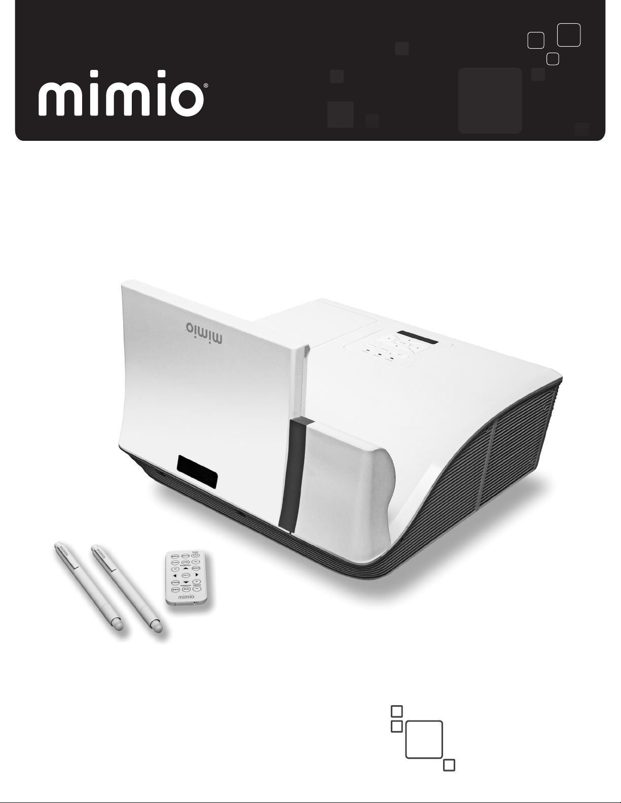
MimioProjector 280, 280I, & 280T
User Guide
mimio.com
Page 2

© 2015 Mimio. All rights reserved. Revised 10/22/2015.
No part of this document or the software may be reproduced or transmitted in any form or
by any means or translated into another language without the prior written consent of
Mimio.
Mimio, MimioClassroom, MimioProjector, and MimioStudio are registered marks in the
United States and other countries. All other trademarks are the property of their respective
holders.
2
Page 3

Contents
MimioProjector 280
What's Included 8
About MimioProjector 280 9
About the Control Panel 11
About the Remote Control 12
About the Connection Ports 14
Getting Started
Installing the Projector 15
What's Included 15
Mounting MimioProjector 16
Determining Where to Mount MimioProjector 20
Determining Where to Mount MimioProjector with 280T Accessory Kit 24
Placement of 280T Projector with a Framed Whiteboard 30
Placement of 280T Projector with a Frameless Whiteboard 33
Aligning the Projector 37
Focusing the Projected Image 38
Connecting the Projector 39
Connecting to a Computer 39
Connecting to a Video Source 40
Setting Up the Remote Control 41
Turning On the Power 42
Turning Off the Power 43
Status Lights 44
15
7
Changing the Projector Settings
Navigating the Projector Menu 45
Adjusting the 3D Settings 48
3D 48
3D Invert 48
3D Format 48
1080p @24 48
Recommended 3D Glasses 49
Adjusting the Interactive Settings 49
Adjusting the Options 49
Logo 49
45
3
Page 4

Logo Capture 49
Auto Source 50
Input 50
Auto Power Off 50
Lamp Setting 50
Lamp Hours Used (Normal) 50
Lamp Hours Used (ECO) 50
Lamp Life Reminder 50
Lamp Power Mode 50
Clear Lamp Hours 51
Dynamic Black 51
High Altitude 51
Filters Remind 51
Information 52
Adjusting the Picture 52
Color Mode 52
Wall Color 52
Brightness 52
Contrast 52
Sharpness 52
Saturation 53
Hue 53
Gamma 53
Color Temperature 53
Color Space 53
Adjusting the Screen 53
Aspect Ratio 53
Phase 54
Clock 54
Horizontal Position 54
Vertical Position 54
Digital Zoom 54
Vertical Keystone 54
Adjusting the General Settings 54
Language 54
Menu Location 55
Closed Caption 55
VGA OUT (Standby) 55
Auto Screen (12V Out) 55
4
Page 5

Test Pattern 56
Security 56
Setting the Password 56
Reset 56
Adjusting the Volume 57
Mute 57
Volume 57
Microphone Volume 57
MimioProjector Accessory Kits
MimioProjector 280I Accessory Kit: What's Included 58
MimioProjector 280T: What's Included 59
Connecting the IRModule 60
Installing the Laser Curtain 61
Caring for MimioProjector
Replacing the Remote Control Battery 66
Replacing the Lamp 67
Cleaning the Dust Filters 68
Getting Help
Status Lights 70
General Troubleshooting 71
Projector stops responding to all controls 71
Lamp burns out or makes a popping sound 71
Image Troubleshooting 72
No image is displayed 72
A partial, scrolling, or incorrect image is displayed 73
The notebook computer display is not displaying an image 73
Image is unstable or flickering 73
Image has vertical flickering bar 73
Image is out of focus 73
Image is stretched when displaying 16:9 DVD image 74
Image is too small or too large 74
Image is displayed with slanted sides 74
Image is reversed 74
3D Troubleshooting 74
Two images are displayed side-by-side 74
Image not displayed in 3D 74
Sound Troubleshooting 74
58
66
70
5
Page 6

Remote Control Troubleshooting 75
Contacting Mimio 75
Compatibility Modes
VGA Analog 76
PC Signal 76
Extended Wide Timing 77
Component Signal 78
HDMI Digital 79
PC Signal 79
Extended Wide Timing 80
Video Signal 81
HDMI 1.4a Mandatory 3D Timing - Video Signal 81
Technical and Environmental Information
Usage Notice 82
Warnings 82
Precautions 82
Regulation & Safety Notices 83
FCC Notice 83
Notice 83
Caution 83
Operating Conditions 83
Notice: Canadian Users 84
Remarque à L’intention des Utilisateurs Canadiens 84
Declaration of Conformity for EU countries 84
Projector Mount Safety Notices 84
Documentation Feedback 85
76
82
6
Page 7

MimioProjector 280
You can bring interactive teaching into your classroom by pairing the MimioProjector 280
with either a MimioTouch Board or a MimioTeach and a conventional dry erase board. The
MimioProjector 280I Interactive Accessory Kit and MimioProjector 280T Accessory Kit can
also be added to your configuration, providing even more interactive features.
MimioProjector 280 easily connects to your computer and can be used as an interactive
projector, touch projector, or alone as a non-interactive, conventional projector.
MimioProjector 280
You can pair the MimioProjector 280 with a MimioTeach and conventional whiteboard or
with a MimioTouch board.
MimioProjector 280I Interactive Accessory Kit
The MimioProjector 280I Interactive Accessory Kit turns the MimioProjector 280 into an
interactive whiteboard. See MimioProjector Accessory Kits on page 58 for more
information.
MimioProjector 280T Touch Accessory Kit
The MimioProjector 280T Touch Accessory Kit turns the MimioProjector 280 into a touch
projector. See MimioProjector Accessory Kits on page 58 for more information.
7
Page 8
MimioProjector 280
CR2025
3V
1
2
5
7
3
4
6
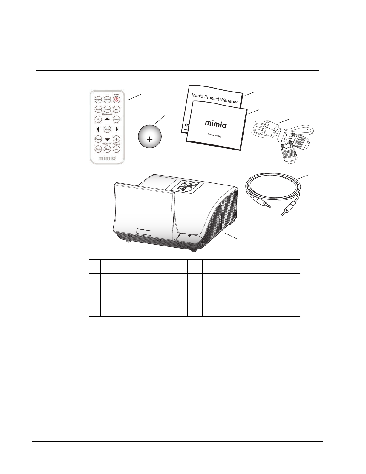
What's Included
The MimioProjector package contains the following items:
1 Remote control 5 5 mm VGA cable
2 Remote control battery 6 5 mm audio cable
3 Mimio Product Warranty card 7 Projector with lens cap
4 Mimio Battery Warning booklet
If you are missing any of the items above, contact Technical Support.
8
Page 9
About MimioProjector 280
1
2
3
4
5
8
10
11
13
11
Front View
Back View
Bottom View
6
7
9
12
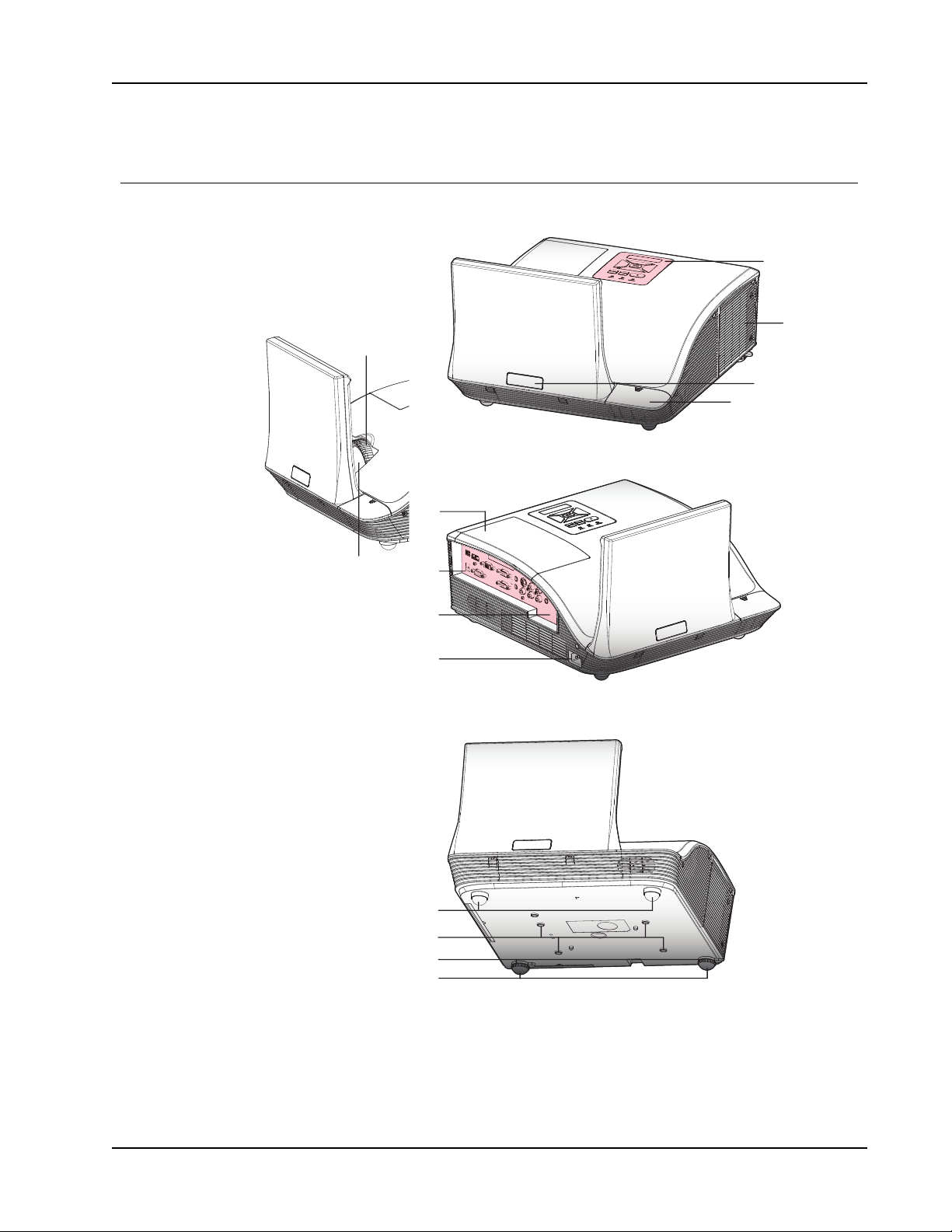
The following figure shows the major components of the MimioProjector 280.
About MimioProjector 280
9
Page 10
MimioProjector 280
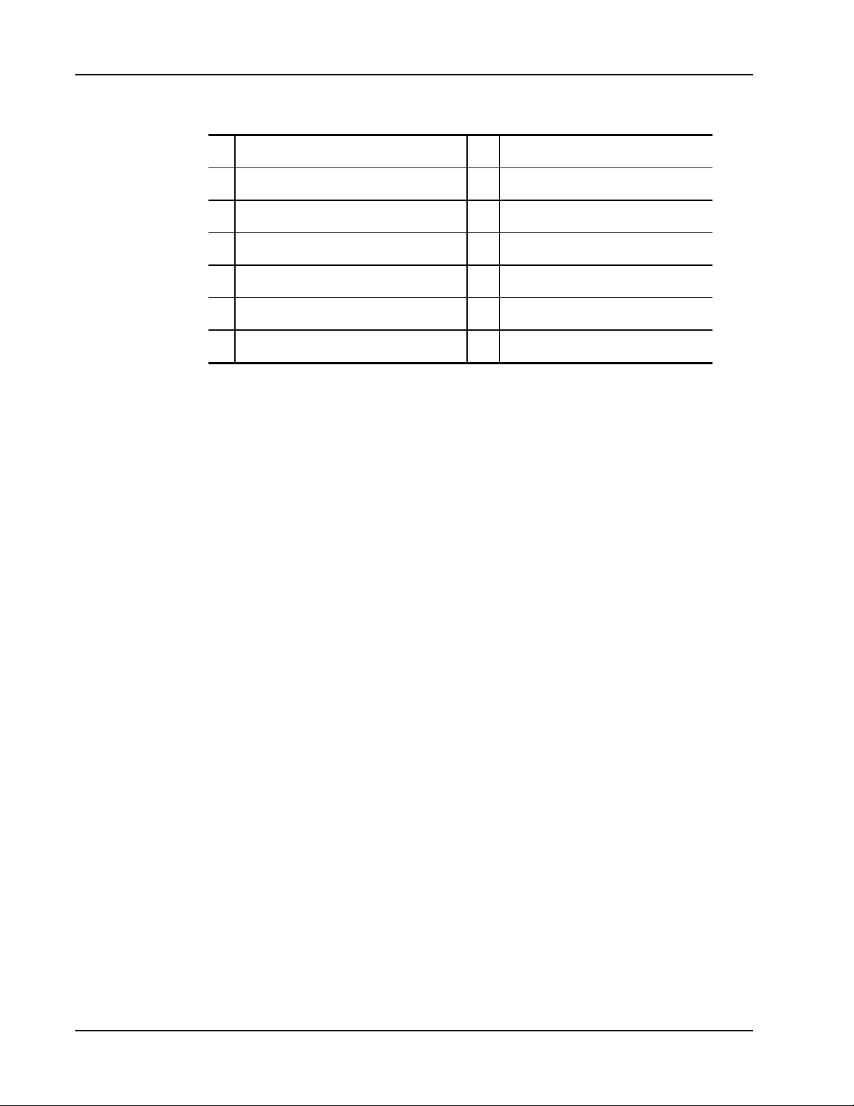
1 Focus ring 8 Input/Output connection ports
2 Lens 9 Serial number
3 Control panel 10 Power connector
4 Lamp cover 11 Elevator feet
5 IR receiver 12 Mounting bracket attachment holes
6 IR Module attachment cover 13 Elevator feet spacers
7 Access cover
10
Page 11
About the Control Panel
MENU
POWER TEMP LAMP
RESYNC
SOURCE
1
MENU
2
4
6
9
8
7
5
3
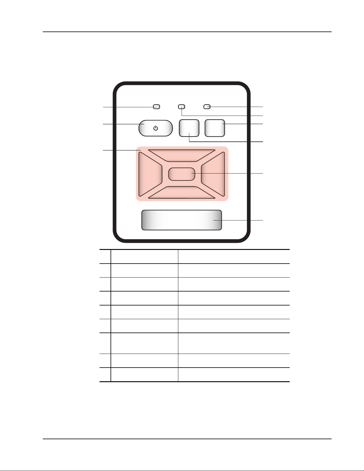
The following figure shows the components of the MimioProjector control panel.
About MimioProjector 280
1 Navigation keys Navigate through menus and make selections.
2 Power button Turn the projector on and off.
3 Power status light Indicates the power status of the projector.
4 Lamp status light Indicates the projector lamp status.
5 Temperature status light Indicates the projector temperature status.
6 Source button Select an input signal.
Automatically synchronize the PC analog timing
7 Resync button
8 Menu/Exit button Open the menu screen or exit a menu.
to the optimized condition.
9 IR receiver Used by remote control.
11
Page 12

MimioProjector 280
1
2
4
6
9
8
7
5
3
10
12
13
14
15
16
11
About the Remote Control
The following figure shows the components of the MimioProjector remote control.
12
Page 13
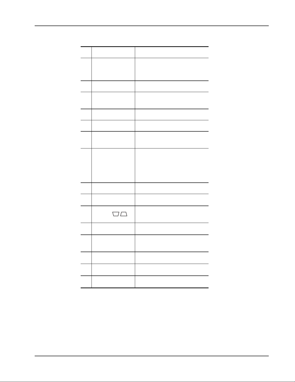
1 Source Select an input signal.
2 Resync Automatically synchronize the
PCanalog timing to the optimized
condition.
3 HDMI Switch to HDMIinput.
About MimioProjector 280
4 Video
Switch to Composite Video or SVideo input.
5 3D Turn on and off the 3D menu.
6 Menu Open the menu screen or exit a menu.
7 Freeze
Freeze or unfreeze the image on the
screen.
Hide or show the screen image.
Audio is not affected when screen
8 Blank
image is hidden. When Blank is
activated, an icon appears in the upperleft corner of the screen.
9 Power Turn the projector on or off.
PC Switch to VGA-A/VGA-B input.
10
Keystone /
11
12
Aspect ratio Select the desired aspect ratio.
Adjust image until the sides are
vertical.
Navigation keys Navigate through menus and make
13
selections.
Volume up Increase the audio volume.
14
15
Volume down Decrease the audio volume.
16
Mute Mute the audio.
13
Page 14
MimioProjector 280
1
2 4
7
109
8
6
3
11 12 13 14 15 16 18
LAN
5
17
About the Connection Ports
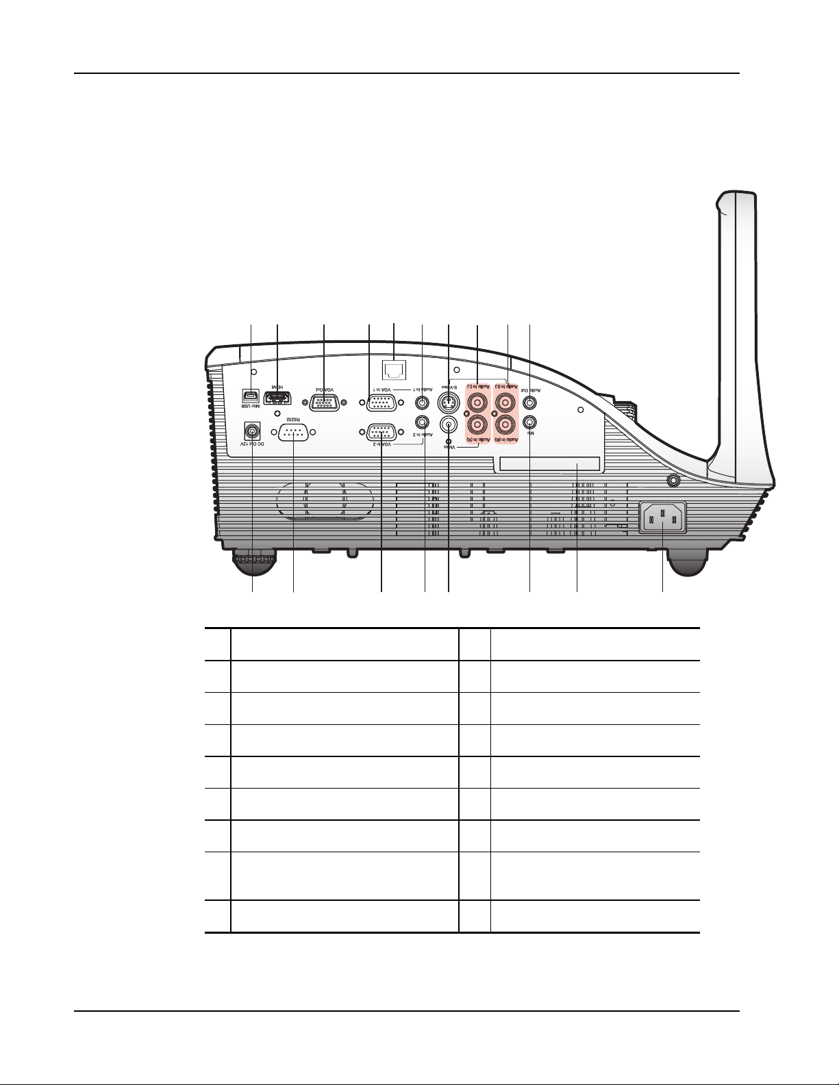
The following figure shows the connection ports available on the MimioProjector .
14
1 Mini-USB 10 Audio output
2 HDMI 11 Laser curtain
3 VGA output 12 RS232
4 VGA in 1 13 Audio in 2 (for VGA in 2)
5 LAN RJ46 14 Audio in 2 (for VGA in 2)
6 Audio in 1 (for VGA in 1) 15 Video
7 S-Video 16 Microphone
8
9 Left/Right RCA audio input (for S-Video) 18 Power
Left/Right RCA audio input (for
composite video input)
17 Serial number
Page 15
Review this chapter to install and start using your MimioProjector.
1 2 3 4 5 6 7
8 9 10 11
13
14
15
12
Installing the Projector
This section describes how to install and align the MimioProjector and wall mount.
What's Included
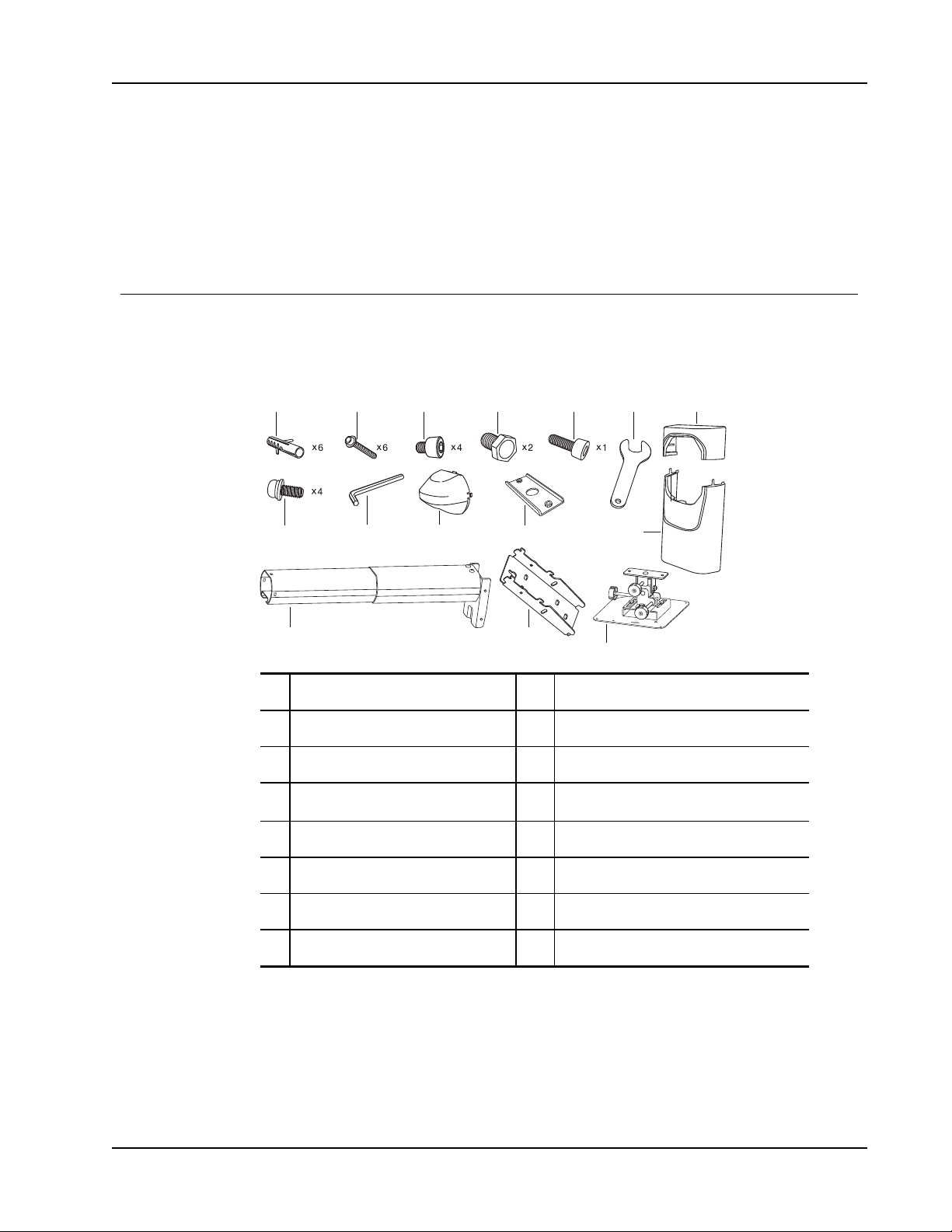
The MimioProjector mount package contains the following items:
Installing the Projector
Getting Started
1 Wall anchors 9 Hex wrench
2 Flange head cap screw 10 Mounting arm cover
3 Socket head cap screw 11 Clamping plate
4 Cap head screw
5 Socket head cap screw 13 Mounting arm
6 Wrench 14 Mounting arm wall bracket
7 Wall mount cover top 15 Projector mounting plate
8 Machine screw and washer
If you are missing any of the items above, contact Technical Support.
12
Wall mount cover bottom
15
Page 16
Getting Started
Mounting MimioProjector
Before installing the projector wall mount, you must first determine the projected image
size. This will determine the placement of the mount on the wall as well as the distance of
the projector from the wall. See Determining Where to Mount MimioProjector on page 20
for more information.
WARNING: Failure to provide adequate structural strength for the wall mount and
projector can result in serious personal injury or damage to equipment. It is the
installer’s responsibility to make sure the structure to which the wall mount is attached
can support five times the combined weight of all equipment. Reinforce the structure as
required before installing the wall mount.
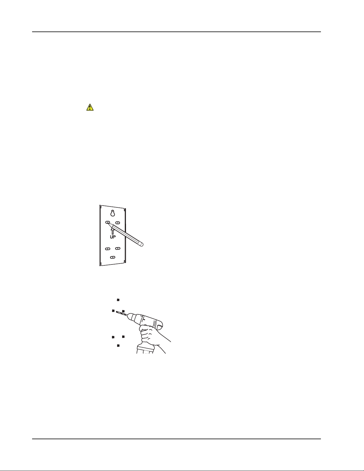
To install the projector wall mount
1. Determine the desired location of the projector wall mount.
See Determining Where to Mount MimioProjector on page 20 for more information.
2. Tape the included template to the wall in the desired location, based on the desired
image size.
3. Using a pencil, make a mark on the wall for each hole indicated on the template.
16
4. Drill a hole in the location of each mark you made on the wall. There will be a total of
six holes.
5. Remove the template from the wall.
Page 17
Installing the Projector
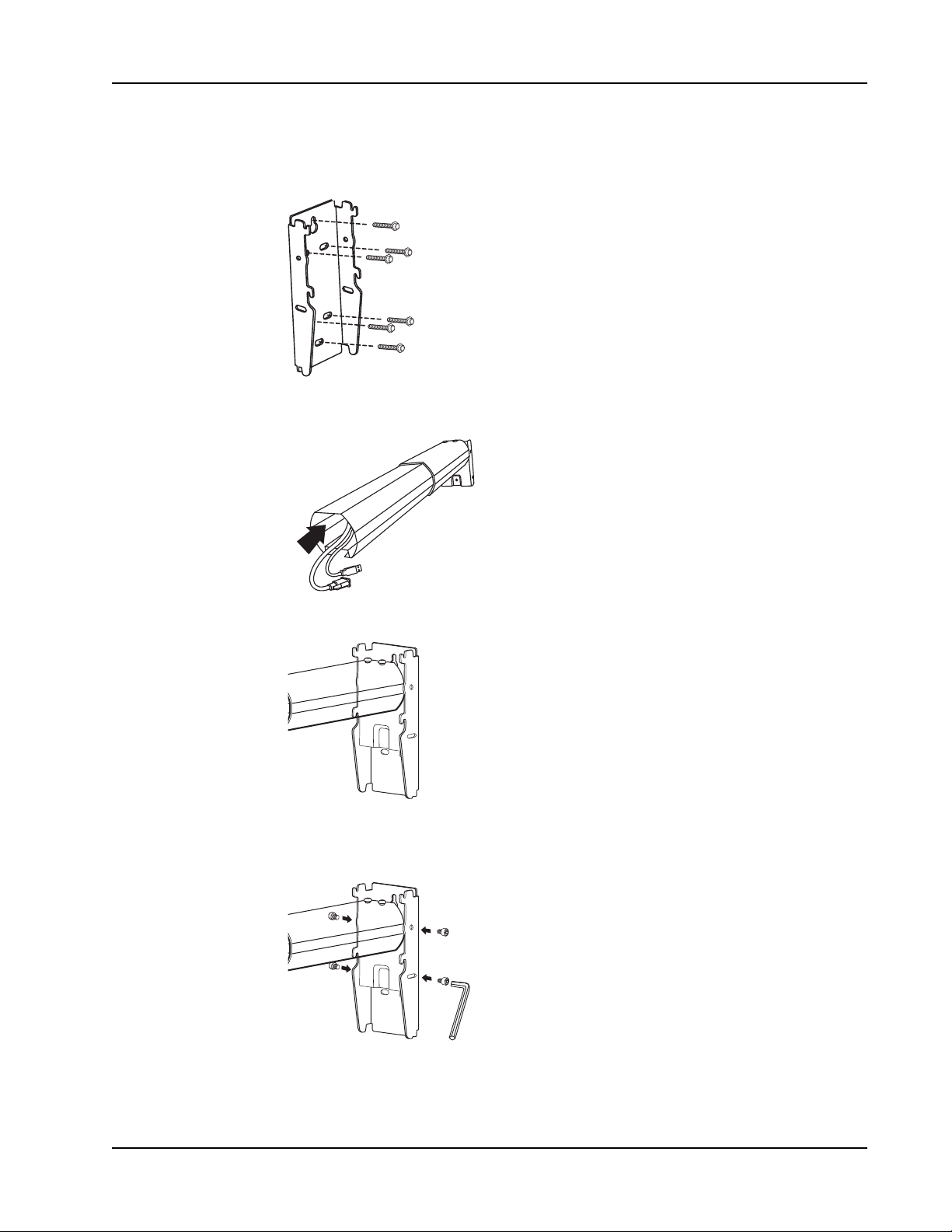
6. Align the holes on the wall mount bracket with the holes that you drilled and attach
the bracket to the wall using fasteners appropriate to the wall surface type.
7. Feed all projector cables through the mounting arm.
8. Insert the mounting arm into the wall bracket.
9. Insert a screw into each of the four holes on the sides of the wall bracket and tighten
using the included allen wrench.
17
Page 18
Getting Started
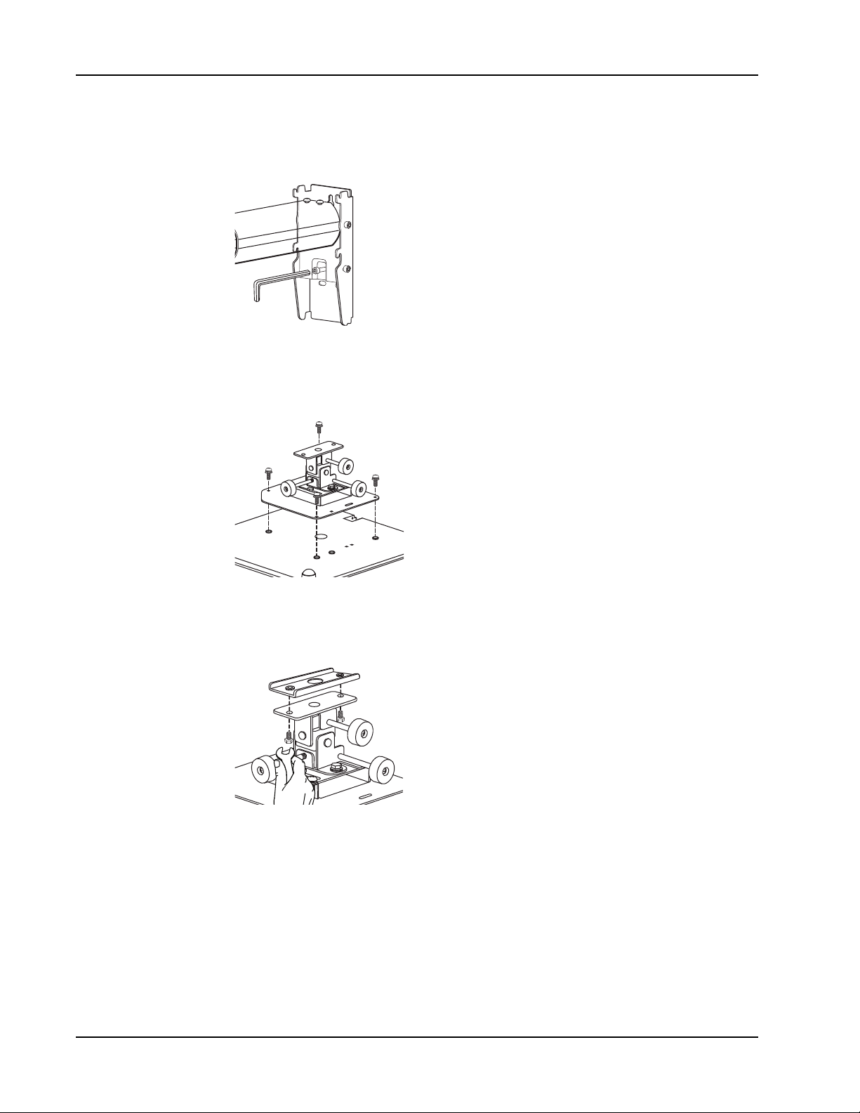
10. Insert the long socket head cap screw into the hole in the center of the wall bracket,
below the mounting arm, and tighten using the included hex wrench.
This screw allows for leveling the mounting arm.
11. Align the holes in the projector mounting plate with the holes on the bottom of the
projector and screw into place using the machine screws and washers.
12. Align the holes on the clamping plate with the holes on the back of the mounting plate
and screw into place using the cap head screws.
18
Page 19
Installing the Projector
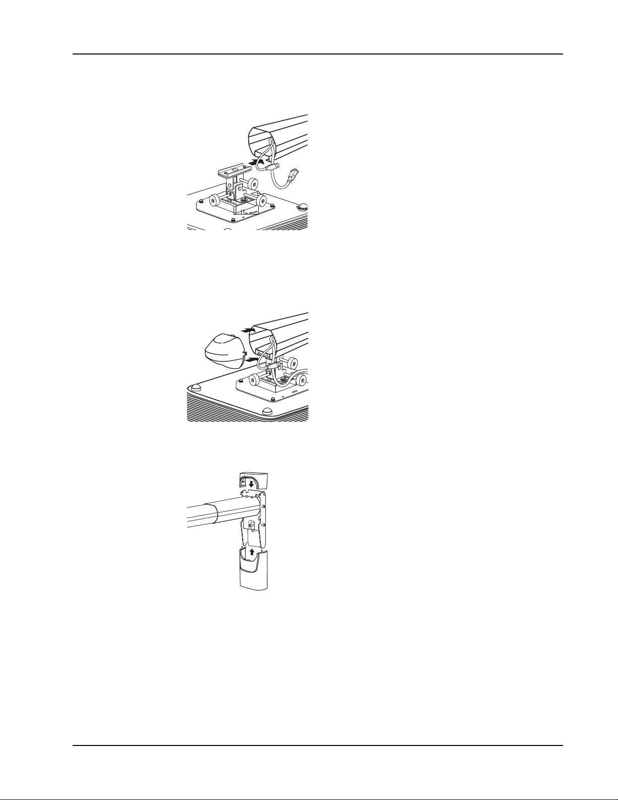
13. Slide the projector mounting plate into the mounting arm as shown.
14. Plug the cables into the appropriate ports on the projector. See Connecting the
Projector on page 39 for more information.
15. Slide the mounting arm cover onto the end of the mounting arm and push to lock in
place..
16. Slide the wall bracket covers onto the top and bottom of the wall bracket and push to
lock in place.
19
Page 20
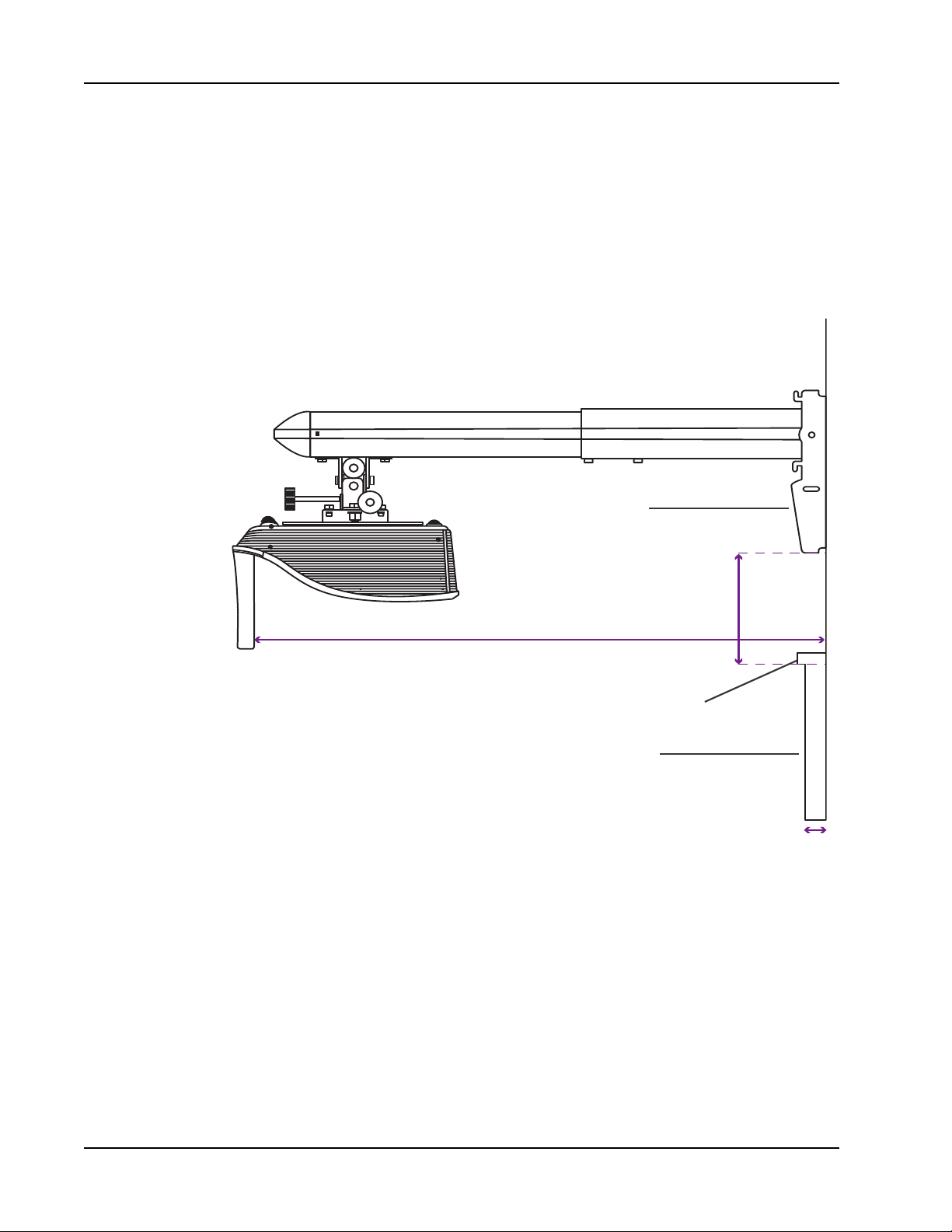
Getting Started
Whiteboard
W
hiteboard
Frame
Wall Bracket
(D) Distance from Wall
(
W) Distance of Whiteboard Surface from Wall
(H) Bracket Height
This distance is to the top of the
whiteboard, not to the top of the frame.
Determining Where to Mount MimioProjector
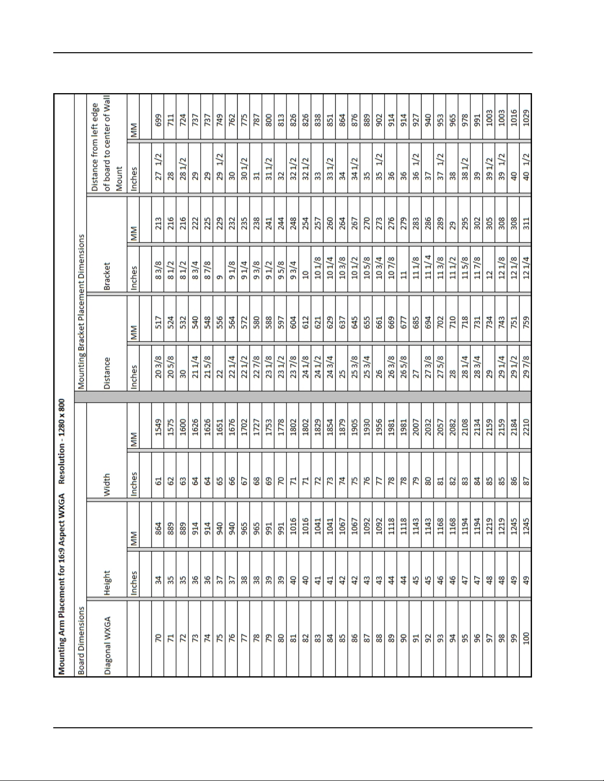
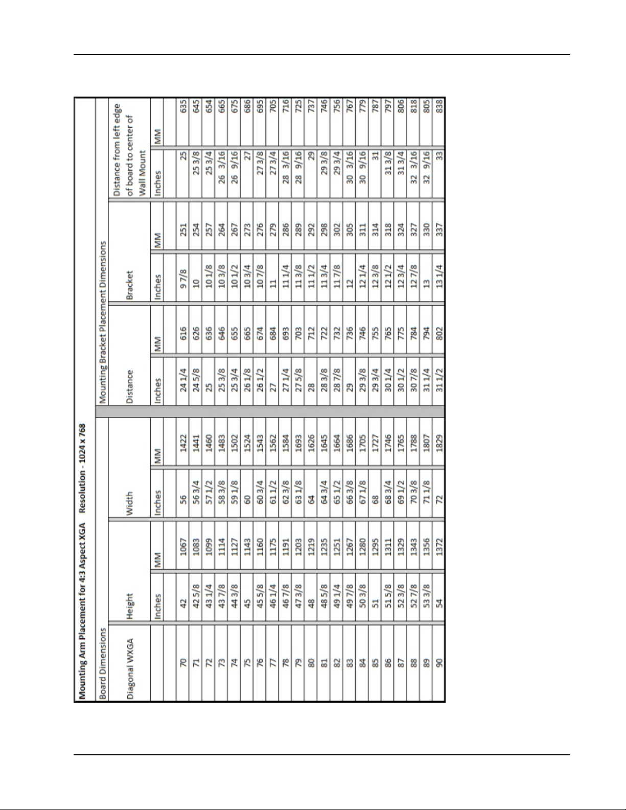
To determine where to mount the MimioProjector mounting arm and the placement of the
MimioProjector 280 on the mounting arm, refer to the charts on page 22 and on page 23.
Select the diagonal (WXGA or XGA) and use the dimensions shown.
If mounting the projector for use as a touch projector, with the MimioProjector 280T
Accessory Kit, see Determining Where to Mount MimioProjector with 280T Accessory
Kit on page 24.
20
Page 21
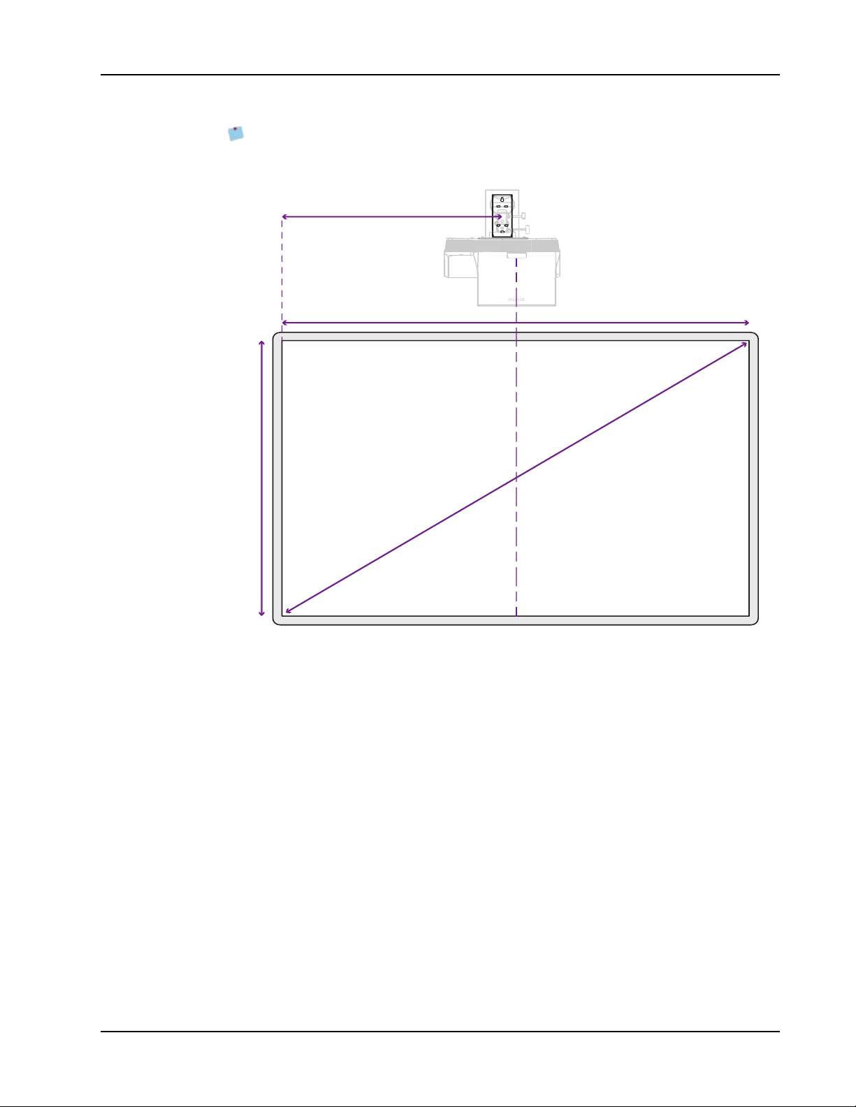
Installing the Projector
(B) Bracket Distance
The projector lens needs to be
centered to the whiteboard.
Wall Bracket
Di
a
gonal Distance
When centering on your whiteboard, position the lens of the projector at the horizontal
center of the board. The wall mount bracket is offset 3 inches (76 mm) from the center
of the lens.
21
Page 22
Getting Started
22
Page 23
Installing the Projector
23
Page 24

Getting Started
Determining Where to Mount MimioProjector with 280T Accessory Kit
This section describes how to determine where to mount the MimioProjector 280 for use as
a touch projector, with the MimioProjector 280T Accessory Kit.
n Determining Where to Mount MimioProjector 280T with a Standard 78-inch
Diagonal WXGA Viewing Image on page 25
n Determining Where to Mount a MimioProjector 280T wit a Standard 87-inch
Diagonal WXGA Viewing Image on page 27
n Placement of 280T Projector with a Framed Whiteboard on page 30
n Placement of 280T Projector with a Frameless Whiteboard on page 33
24
Page 25
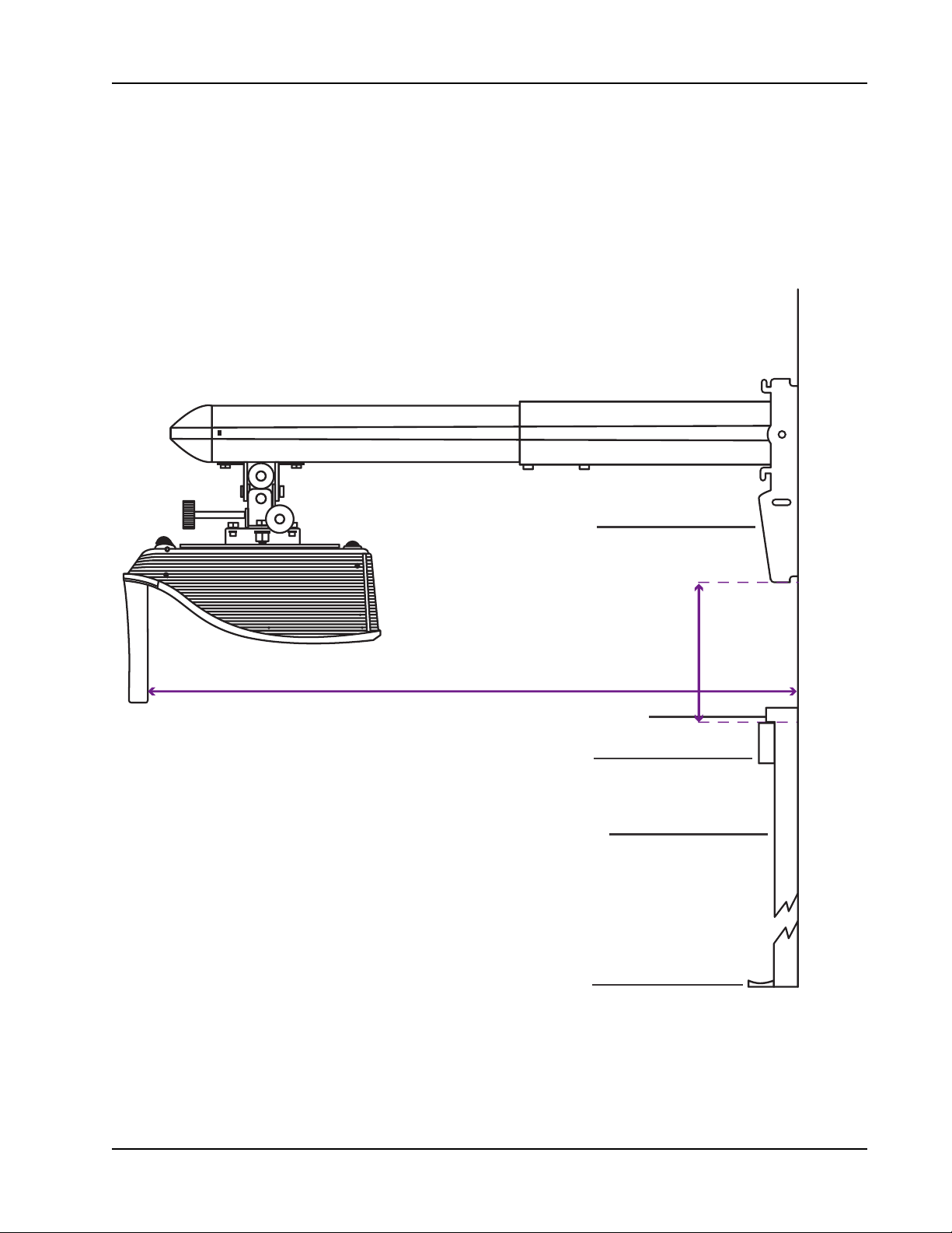
Installing the Projector
Whiteboard
Pen Tray
Whiteboard
Frame
Wall Bracket
Laser Curtain
22 7/8 in. Distance from Wall
9 3/8 in. Bracket Height
This distance is to the top of the
whiteboard, not to the top of the frame.
Determining Where to Mount MimioProjector 280T with a Standard 78-inch
Diagonal WXGA Viewing Image
This section describes how to determine where to mount the MimioProjector 280 for use as
a touch projector, with the MimioProjector 280T Accessory Kit and a standard 78-inch
whiteboard.
25
Page 26
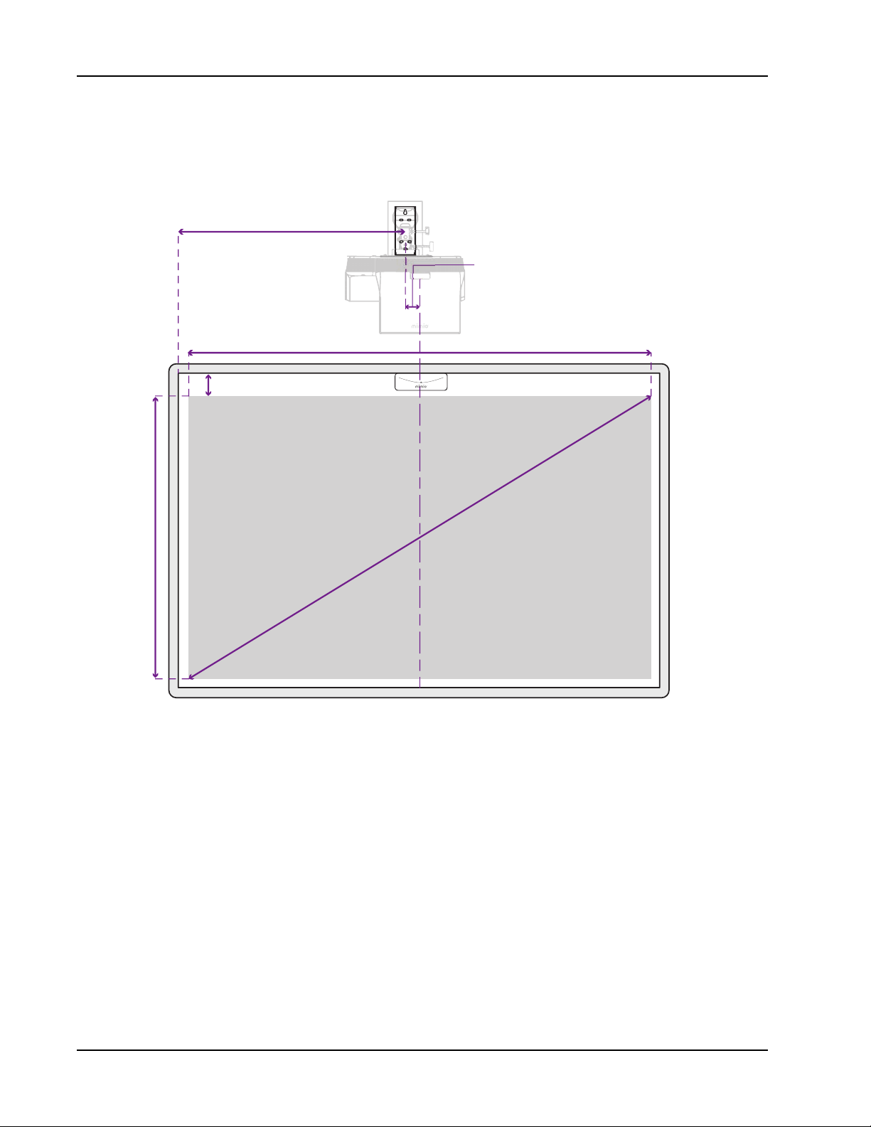
Getting Started
31 in.
The projector lens needs to be
centered to the whiteboard.
Wall Bracket
Desired Projected Image
78 in. Diagonal Distanc
e
3 in.
Wall bracket center should be oset
3 in. from the center of projector lens.
38 in.
68 in.
When centering on your whiteboard, position the lens of the projector at the horizontal
center of the board. The wall mount bracket is offset 3 inches (76 mm) from the center of the
lens.
26
Page 27
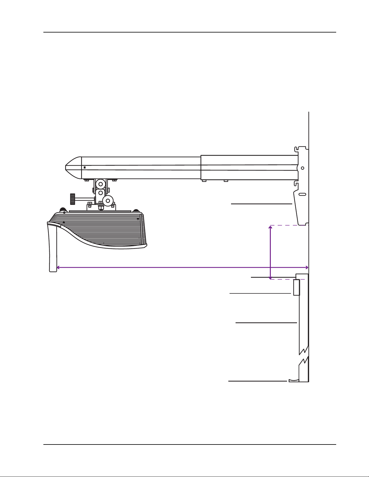
Installing the Projector
Whiteboard
Whiteboard
Frame
Wall Bracket
Laser Curtain
25 3/4 in. Distance from Wall
10 5/8 in. Bracket Height
This distance is to the top of the
whiteboard, not to the top of the frame.
Determining Where to Mount a MimioProjector 280T wit a Standard 87inch Diagonal WXGA Viewing Image
This section describes how to determine where to mount the MimioProjector 280 for use as
a touch projector, with the MimioProjector 280T Accessory Kit and a standard 87-inch
whiteboard.
27
Page 28
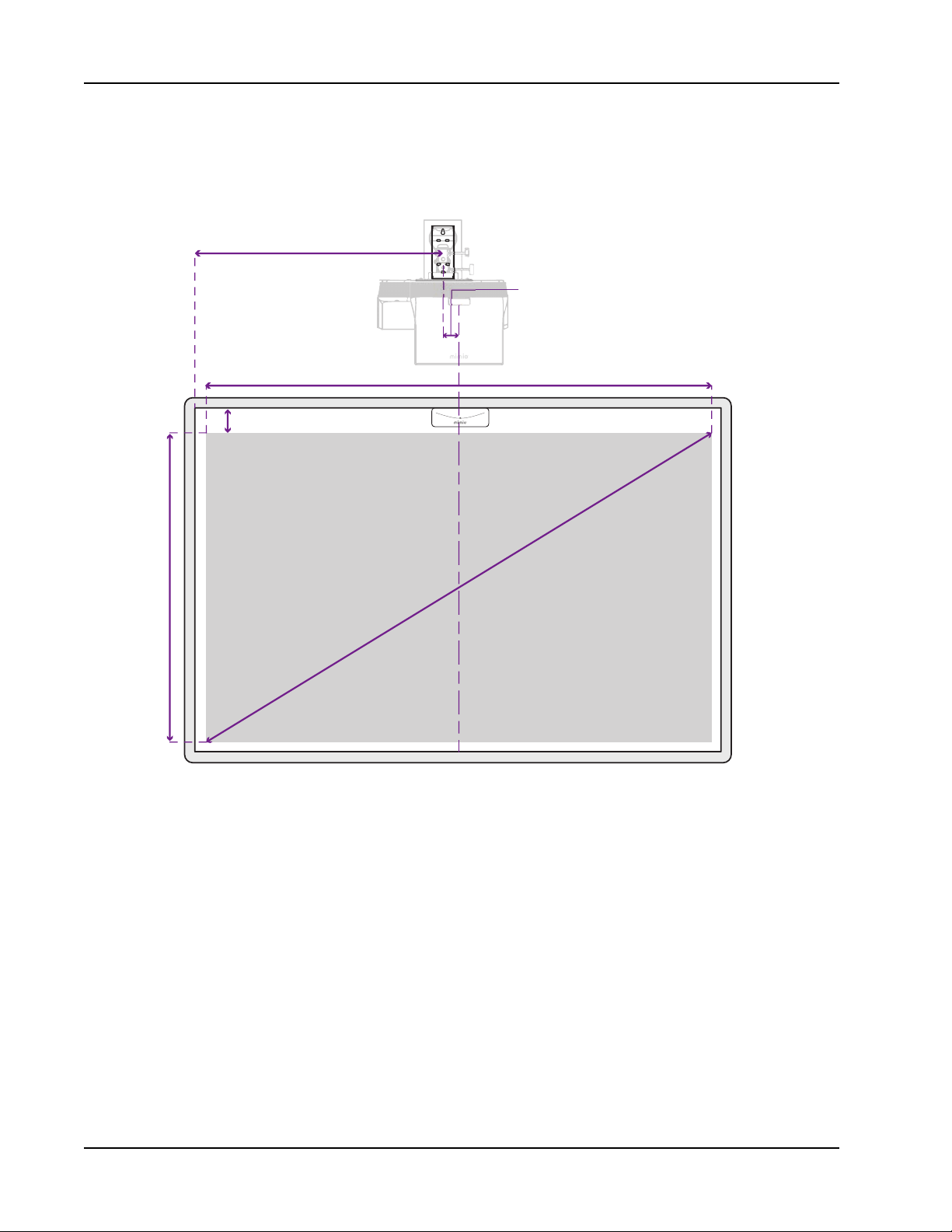
Getting Started
35 in.
The projector lens needs to be
centered to the whiteboard.
Wall Bracket
Desired Projected Image
87 in. Diagonal Distanc
e
3 in.
Wall bracket center should be oset
3 in. from the center of projector lens.
43 in.
76 in.
When centering on your whiteboard, position the lens of the projector at the horizontal
center of the board. The wall mount bracket is offset 3 inches (76 mm) from the center of the
lens.
28
Page 29
Installing the Projector
Determining Where to Mount MimioProjector with 280T Accessory Kit
(Framed Whiteboard)
This section describes how to determine where to mount the MimioProjector 280 for use as
a touch projector, with the MimioProjector 280T Accessory Kit and a framed non-standard
sized whiteboard.
To determine the mounting location for MimioProjector 280T for use with a framed
whiteboard
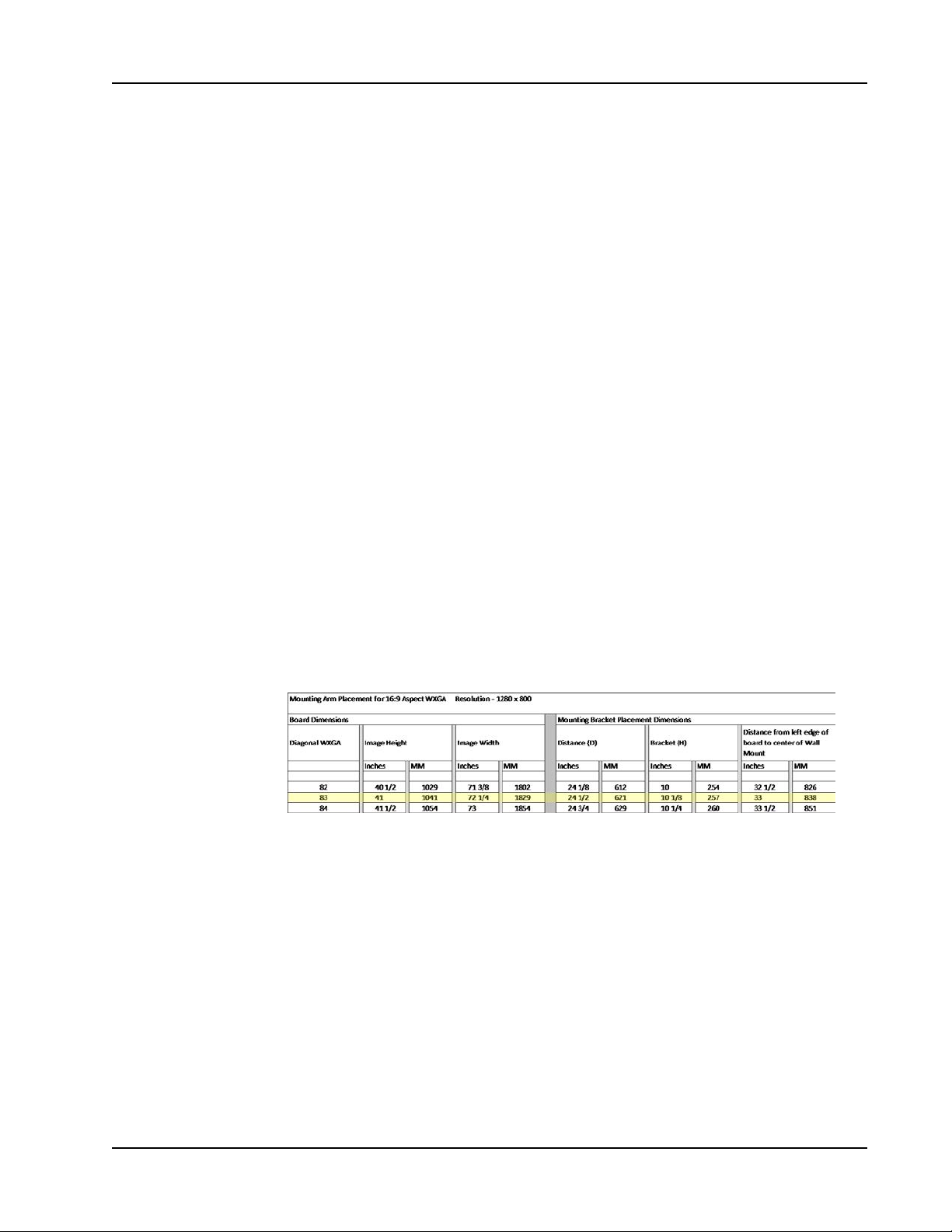
1. a. Measure the height and width of the interior surface of your whiteboard (do not
include the frame in your measurements).
Example: 47 inches high by 78¼ inches wide
b. Subtract 6 inches from the height of your whiteboard.
Example: 47 inches - 6 inches = 41 inches
c. Subtract 6 inches from the width of your whiteboard.
Example: 78¼ inches - 6 inches = 72¼ inches
2. Using the chart on page 1, find the height closest, without going over, to the number
calculated in step 2.
3. Do the following:
a. If the corresponding width listed in that row of the chart is not greater than the
number calculated in step 3, use the information in this row to determine where to
mount the projector mounting arm and projector.
b. If the corresponding width listed in that row of the chart is greater than the number
calculated in step 3, find the row that contains the number closest, without going
over, to the number calculated in step 3. Use the information in this row to
determine where to mount the projector mounting arm and projector.
See the complete chart on on page 1.
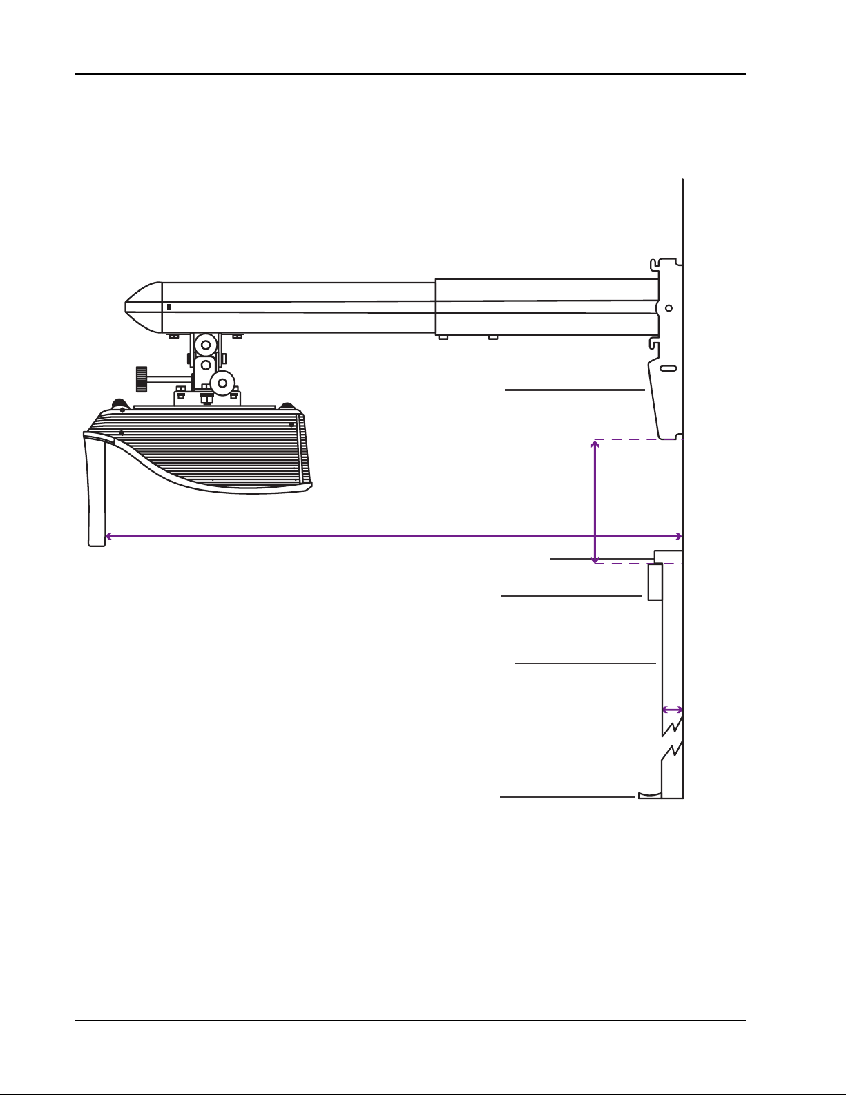
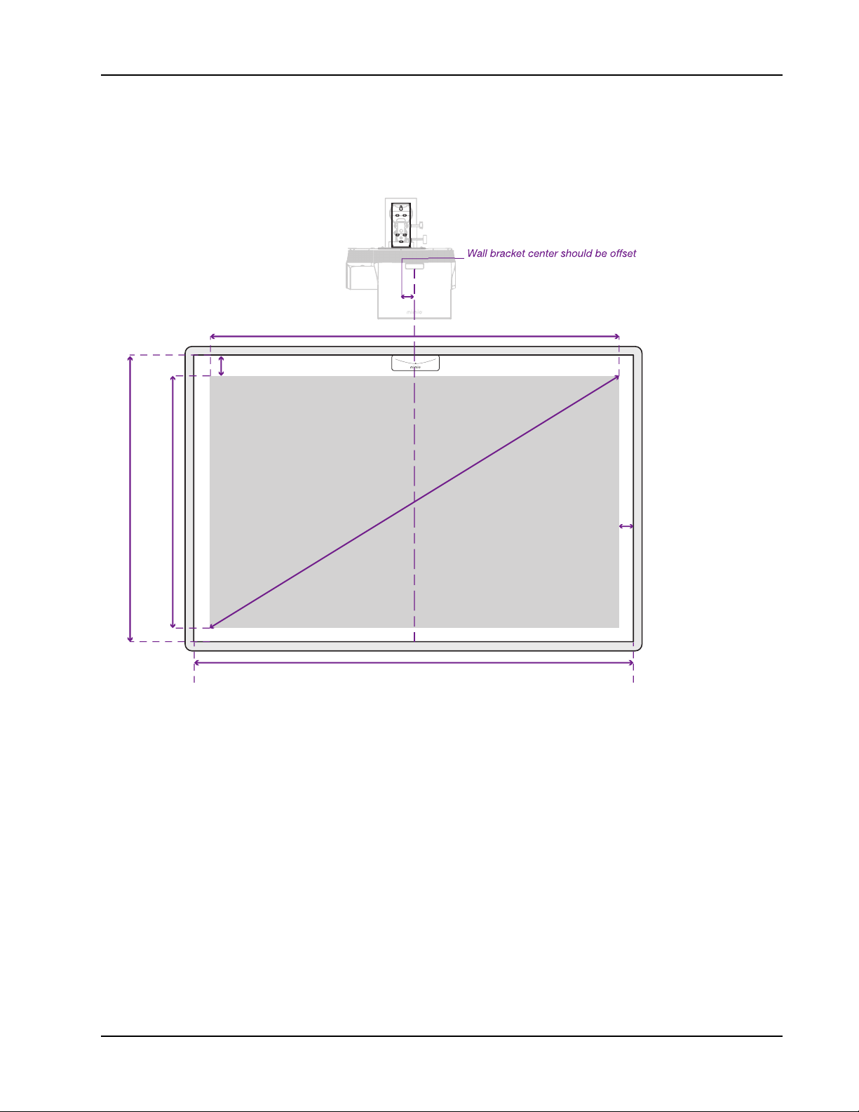
4. Use the following images and the instructions on Mounting MimioProjector on page
16 to install the projector mount and projector.
29
Page 30
Getting Started
(W) D istance of Whi teboa rd Su rface from Wa ll
Whiteboard
Pen Tray
Whiteboard
Frame
Wall Bracket
Laser Curtain
(D). Distance from Wall
(H). B rac ket Hei ght
This distance is to the top of the
whiteboard, not to the top of the frame.
Placement of
280T Projector with a
Framed Whiteboard
30
Page 31
Installing the Projector
The projector lens needs to be
centered to the whiteboard.
Wall Bracket
Desired Projected Image
Diag
o
na
l
Distance
3 in.
Be sure to have
3 in. of clearence
from all sides of the
frame and pen tray.
(C )
BH )
(BW )
(E )
3 in. from the center of projector lens.
When centering on your whiteboard, position the lens of the projector at the horizontal
center of the board. The wall mount bracket is offset 3 inches (76 mm) from the center of the
lens.
31
Page 32
Getting Started
Determining Where to Mount MimioProjector with 280T Accessory Kit
(Frameless Whiteboard)
This section describes how to determine where to mount the MimioProjector 280 for use as
a touch projector, with the MimioProjector 280T Accessory Kit and a frameless nonstandard sized whiteboard.
To determine the mounting location for MimioProjector 280T for use with a
frameless whiteboard
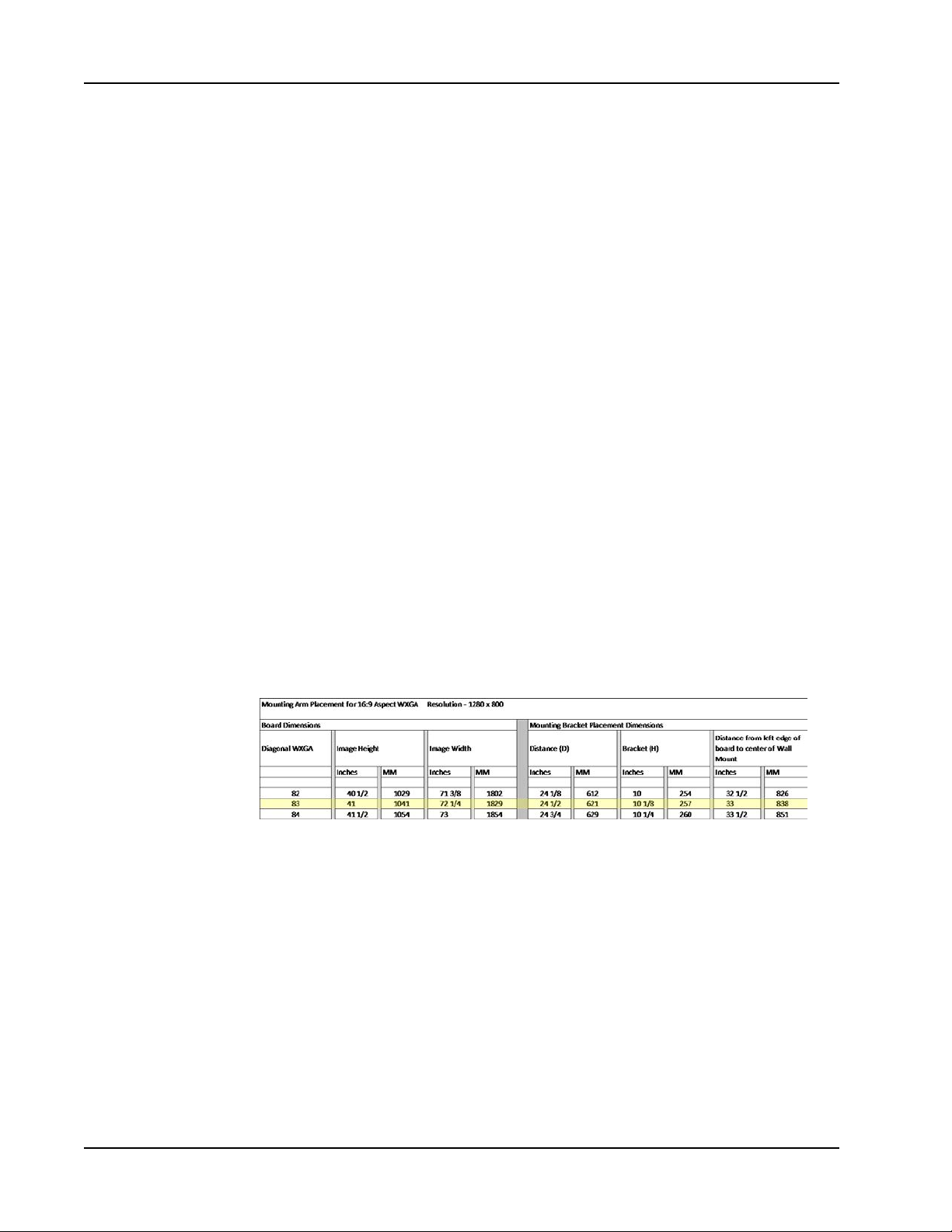
1. a. Measure the height and width of the interior surface of your whiteboard.
Example: 45 inches high by 74¼ inches wide
b. Subtract 4 inches from the height of your whiteboard.
Example: 45 inches - 4 inches = 41 inches
c. Subtract 6 inches from the width of your whiteboard.
Example: 74¼ inches - 2 inches = 72¼ inches
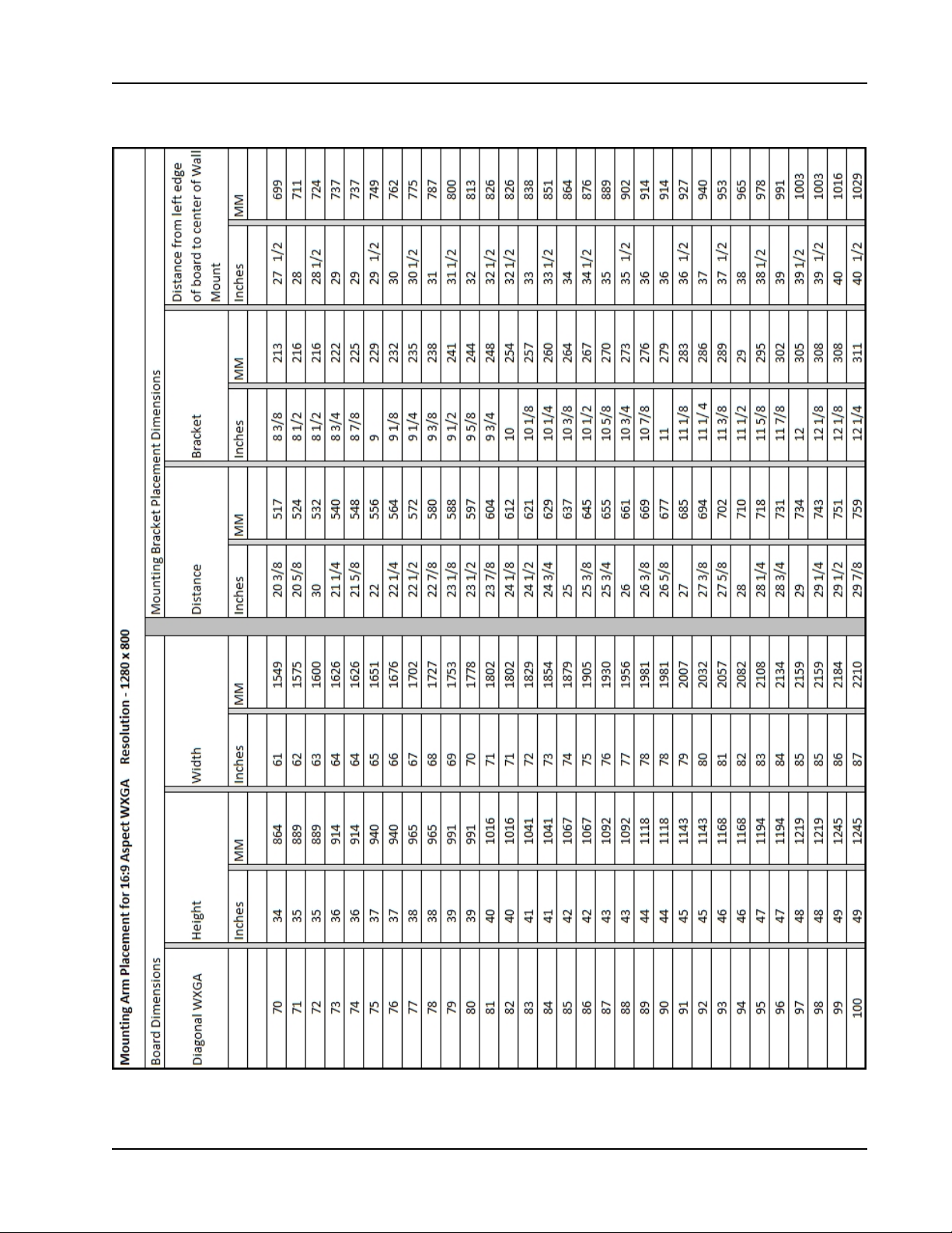
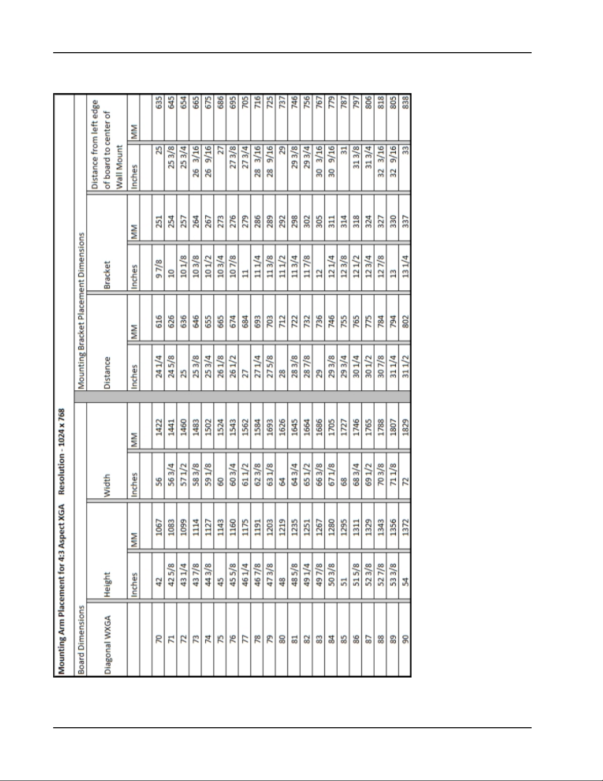
2. Using the on page 1 chart, find the height closest, without going over, to the number
calculated in step 2.
3. Do the following:
a. If the corresponding width listed in that row of the chart is not greater than the
number calculated in step 3, use the information in this row to determine where to
mount the projector mounting arm and projector.
b. If the corresponding width listed in that row of the chart is greater than the number
calculated in step 3, find the row that contains the number closest, without going
over, to the number calculated in step 3. Use the information in this row to
determine where to mount the projector mounting arm and projector.
32
See the complete chart on on page 1.
4. Use the following images and the instructions on Mounting MimioProjector on page
16 to install the projector mount and projector.
Page 33
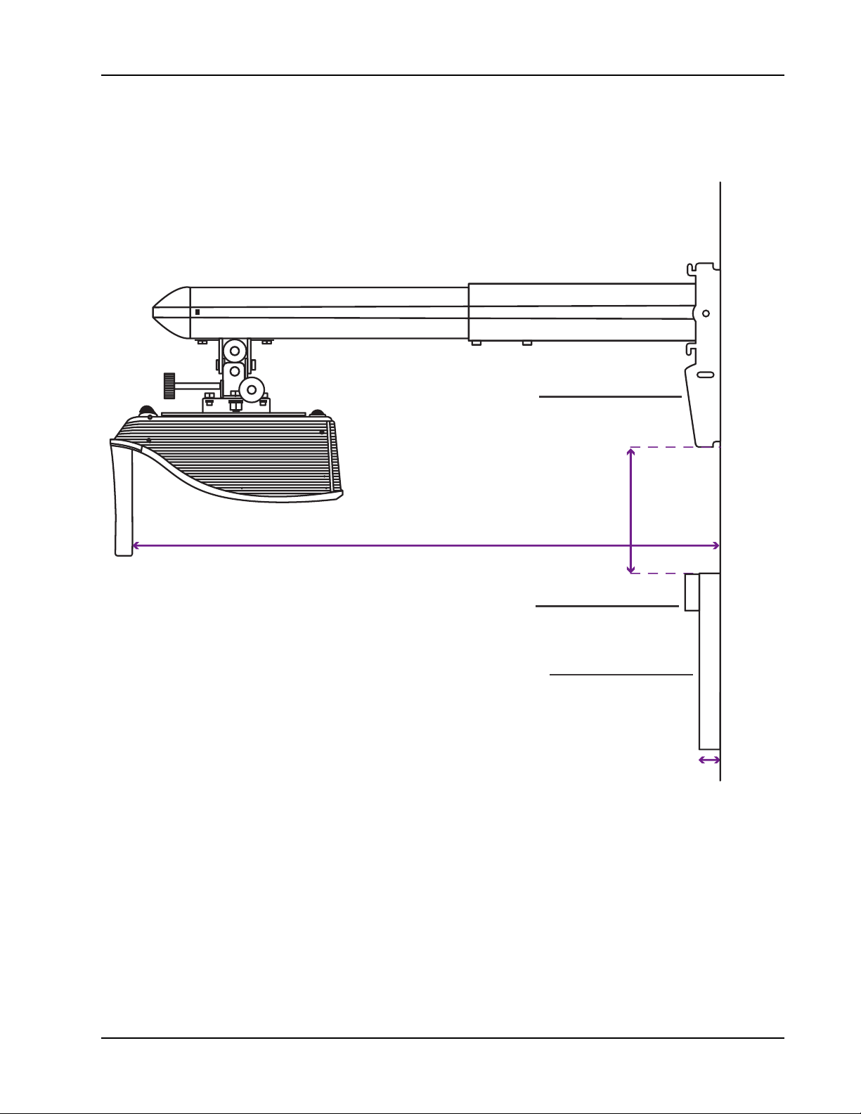
Installing the Projector
(W) D istance of Whi teboa rd Su rface from Wa ll
Whiteboard
Wall Bracket
Laser Curtain
(D). Distance from Wall
(H). B rac ket Hei ght
This distance is to the top
of the whiteboard.
Placement of
280T Projector with a
Frameless Whiteboard
33
Page 34
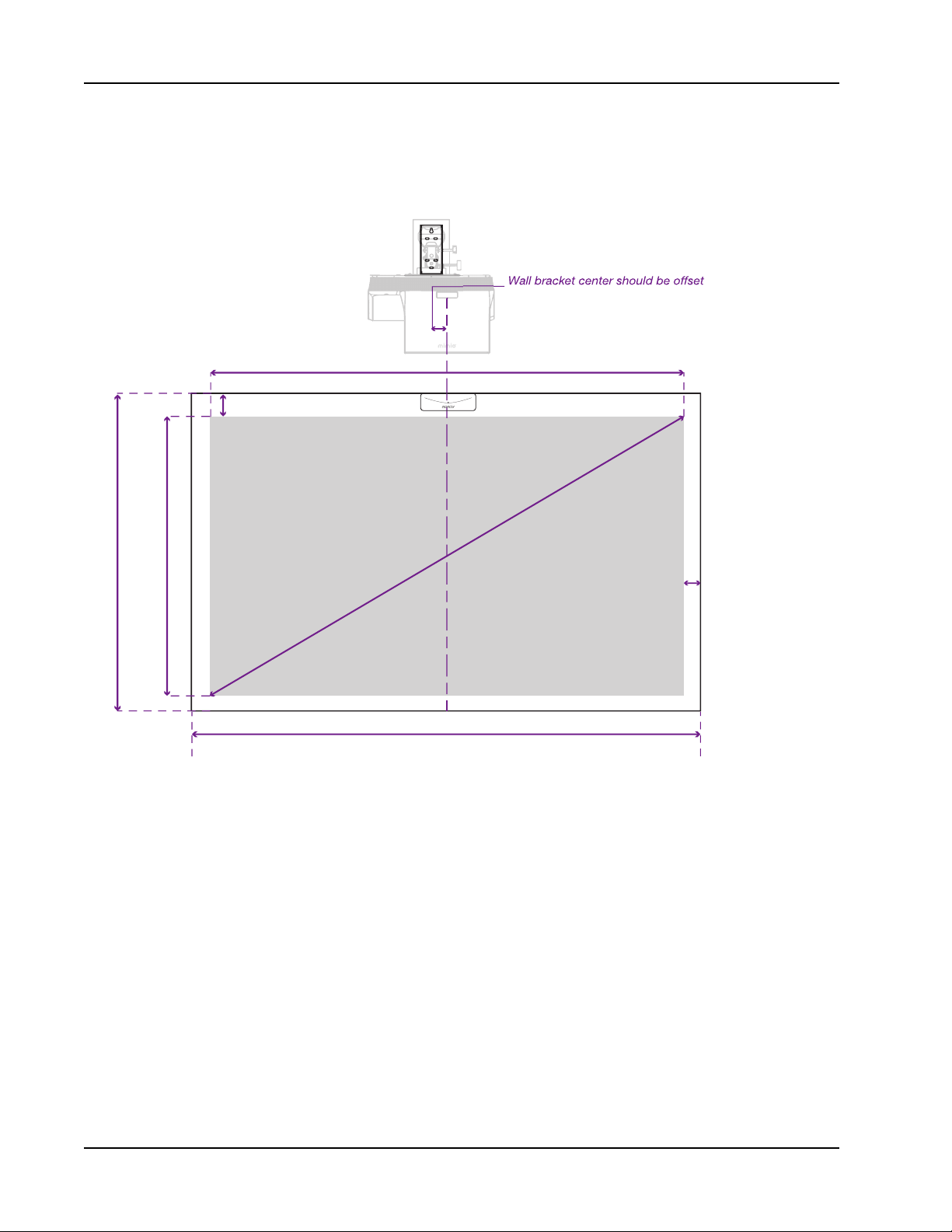
Getting Started
The projector lens needs to be
centered to the whiteboard.
Wall Bracket
Desired Projected Image
Diag
o
na
l
Distance
3 in.
Be sure to have
1 in. of clearence
from the sides
and bottom of
the board.
(C )
BH )
(BW )
(E )
3 in. from the center of projector lens.
When centering on your whiteboard, position the lens of the projector at the horizontal
center of the board. The wall mount bracket is offset 3 inches (76 mm) from the center of the
lens.
34
Page 35
Installing the Projector
35
Page 36
Getting Started
36
Page 37
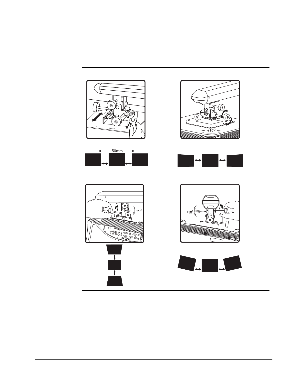
Aligning the Projector
The projector wall mount allows you to adjust MimioProjector in the following ways:
Slide from side to side Rotate horizontally
Installing the Projector
Tilt from front to back Tilt from side to side
37
Page 38
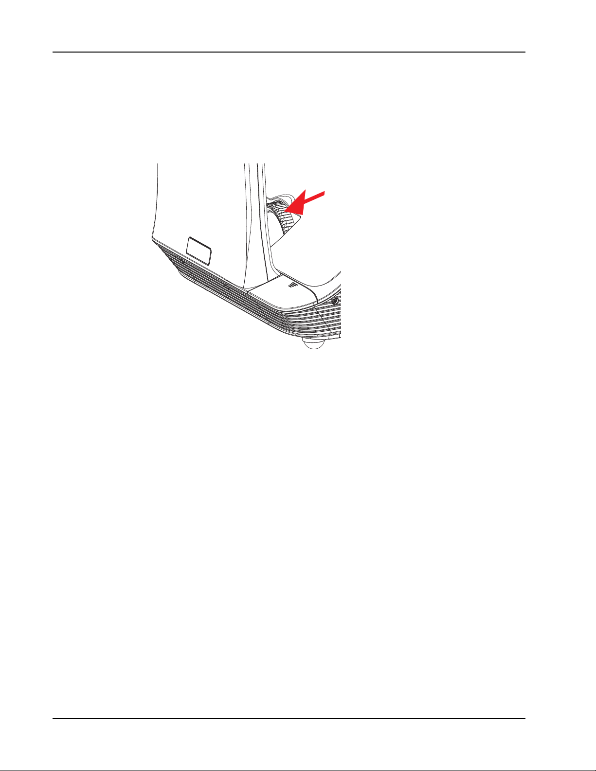
Getting Started
Focusing the Projected Image
Use the focus ring to adjust the focus of the projected image. Turn the ring until the image
is clear.
38
Page 39
Connecting the Projector
LAN
Power outlet
Au
dio output
+12V output
Notebook
Computer
1
2
3 4 7
8
6
5
2
2
4
4
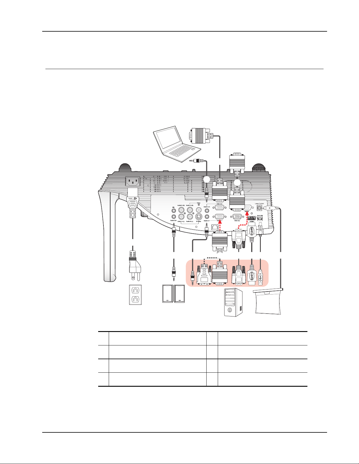
You can connect MimioProjector to a computer or other video source.
Connecting to a Computer
The following figure shows the connection methods available for connecting the
MimioProjector to a computer.
Connecting the Projector
1 Power cord (included) 5 RS232 cable
2 Audio cable 6 HDMI cable
3 VGA to DVI-A cable 7 USB cable
4 VGA cable (included) 8 Laser curtain
39
Page 40
Getting Started
Video output
DVD player, set-top box,
HDTV receiver
Power outlet
Audio output S-Video output
DVD player, set-top box,
HDTV receiver
1 2
3
4
5
6
7
3 8 5
6
5
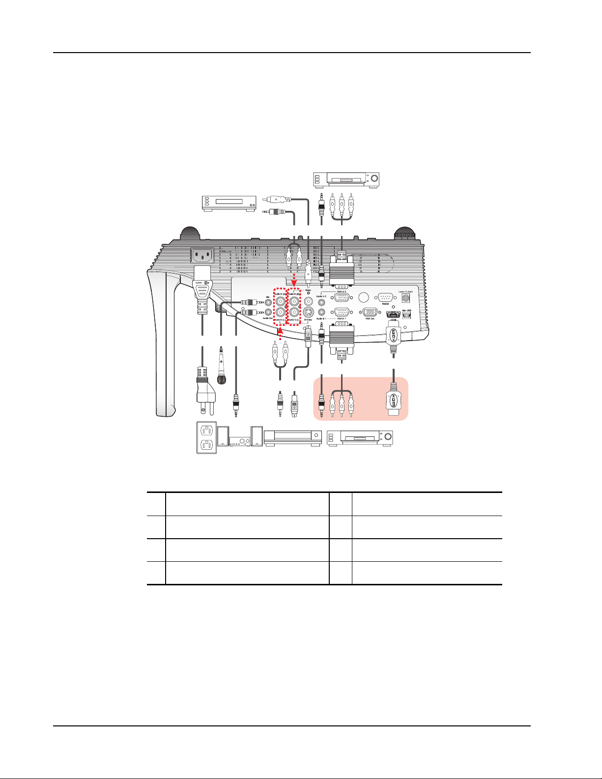
Connecting to a Video Source
The following figure shows the connection methods available for connecting the
MimioProjector to a video source.
1 Power cord (included) 5 Audio cable
2 Microphone cable 6 VGA to HDTV (RCA) cable
3 Audio cable jack/RCA 7 HDMI cable
4 S-Video cable 8 Composite video cable
40
Page 41
Setting Up the Remote Control
3
V
O
L
T
S
CR2025
3
V
O
L
T
S
CR2025
M
3
V
O
L
T
S
CR2025
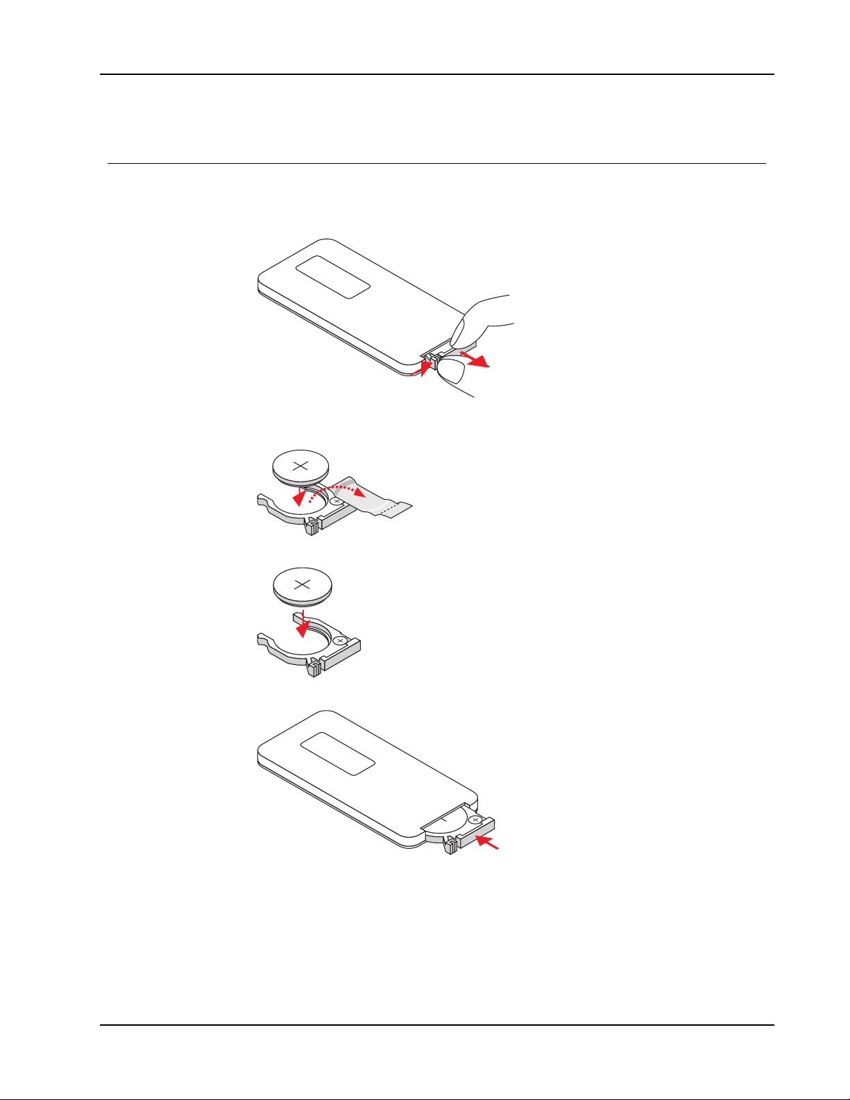
Before using the remote control for the first time, remove the transparent insulation tape.
To set up the remote control
1. Press firmly and slide the battery holder out of the battery compartment.
2. Remove the battery from the battery holder.
3. Remove the transparent insulation tape.
Setting Up the Remote Control
4. Replace the battery holder with the + polarity marking facing up as shown.
5. Slide the battery holder back into the battery compartment and press firmly.
41
Page 42

Getting Started
Turning On the Power
You can power on the projector using the remote control or the control panel on the
projector.
To turn the projector on
1. Securely connect the power cord and audio/video cables.
When connected, the Power status light turns red.
2.
Press on the control panel or on the remote control.
The Power status light turns blue.
3. Turn on the computer, notebook, video player, or other source from which you want to
project an image.
The projector detects the input automatically.
4. If multiple inputs are connected to the projector, press Source on the control panel or
on the remote control to switch between inputs.
42
Page 43

Turning Off the Power
To turn the projector off
1.
Press on the control panel or on the remote control.
A confirmation message is displayed on the projector screen.
2.
Press again to turn the projector off.
The Power status light turns red and blinks rapidly. The projector fans continue to run
for approximately one minute to ensure that the projector cools properly.
When the system is finished cooling, the fans turn off and the Power status light turns
solid red, indicating that the projector is in standby mode.
3. Unplug the power cord.
Turning On the Power
43
Page 44

Getting Started
Status Lights
Lamp status
Message
Standby -- -- ON --
Power button ON -- -- -- ON
Cooling state -- --
Power button OFF
Cooling completed; Standby
mode
Firmware download ON ON ON --
Thermal sensor error
The following message is
displayed:
1. Make sure air inlets and
outlets are not blocked.
2. Make sure the
environment temperature
is under 40°C (104°F)
Fan lock error
The following message is
displayed:
The projector will switch off
automatically.
Lamp error
(lamp, lamp driver, color wheel)
light
Red
-- -- ON --
-- ON -- ON
--
ON -- --
Temperature
status light
Red
0.5 second H
(ON)
0.5 second L
(OFF)
flashing
Power status
light
Red
0.5 second H
(ON)
0.5 second L
(OFF)
flashing
-- ON
Power status
light
Blue
--
ON
44
Page 45
Navigating the Projector Menu
Changing the Projector
Settings
You can adjust the projector image and change the projector settings using the projector
menus. The projector automatically detects the input source.
To change the projector settings
1. Press Menu on the control panel or on the remote control to display the projector main
menu.
2. Use the navigation keys to select the desired menu item.
3.
If the menu item has an arrow icon, , press ► to display the submenu for that
setting, and then use the navigation keys to select the desired menu item.
4. Press ◄ or ► to adjust the selected setting.
5. Press Menu to return to the previous menu or to exit the menu screen.
Navigating the Projector Menu
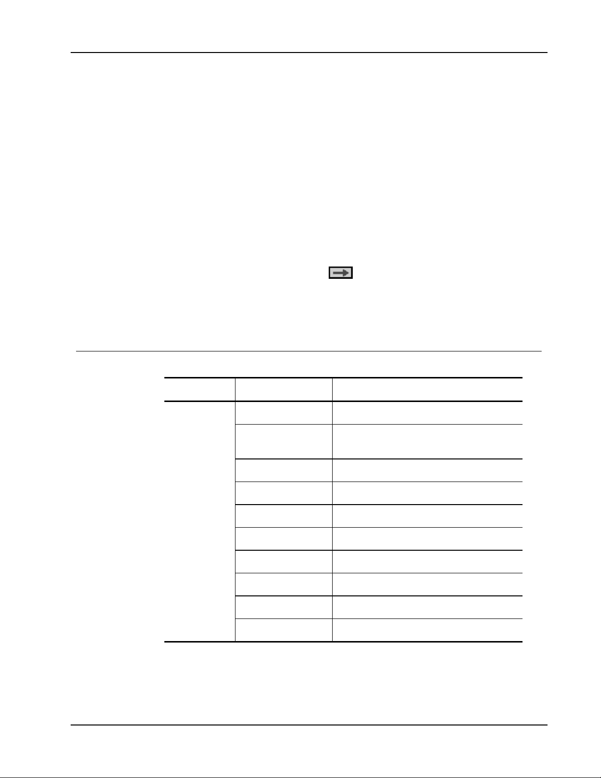
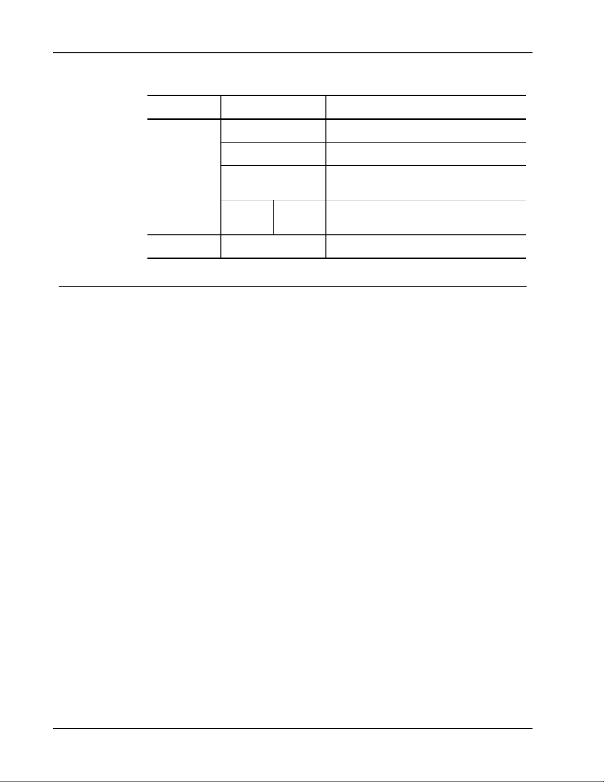
The following table describes the structure of the projector menu and submenus.
Main Menu Submenu Settings
PICTURE Color Mode Brightest / PC / Movie / Game / User
Wall Color White / Light Yellow / Light Blue / Pink / Dark
Brightness 0~100
Contrast 0~100
Sharpness 0~31
Saturation 0~100
Hue 0~100
Gamma 0~3
Color Temp. Low / Mid / High
Green
Color Space AUTO / RGB / YUV
45
Page 46
Changing the Projector Settings
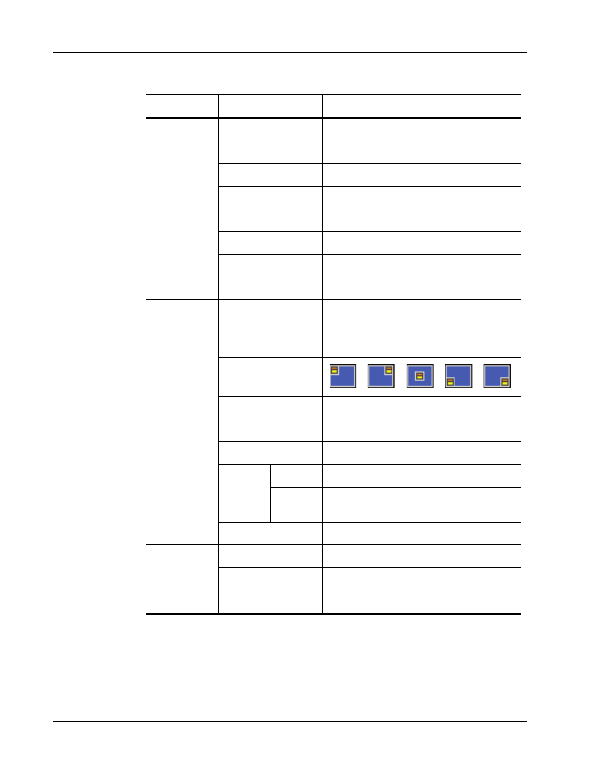
Main Menu Submenu Settings
SCREEN Aspect Ratio AUTO / 4:3 / 16:9 / 16:10
SETTING Language English / Deutsch / Français / Italiano / Español /
Phase 0~31
Clock -50~50
H. Position -10~10
V. Position -10~10
Digital Zoom 1~10
V Keystone -15 / +15
Ceiling Mount Front / Front Ceiling / Rear / Rear Ceiling
Português / Polski / Русский / Svenska / Norsk / 简
体中文 / 日本語 / 한 국 어 / Türkçe / 繁體中 文
/Nederlands / ﻋﺮﺑﻲ
Menu Location
Closed Caption Off / CC1 / CC2 / CC3 / CC4
VGA Out (Standby) Off / On
Test Pattern Off / On
Security Security Off / On
Change
Password
Reset No / Yes
AUDIO Mute Off / On
Volume 0~32
Microphone Volume 0~32
000000
46
Page 47
Main Menu Submenu Settings
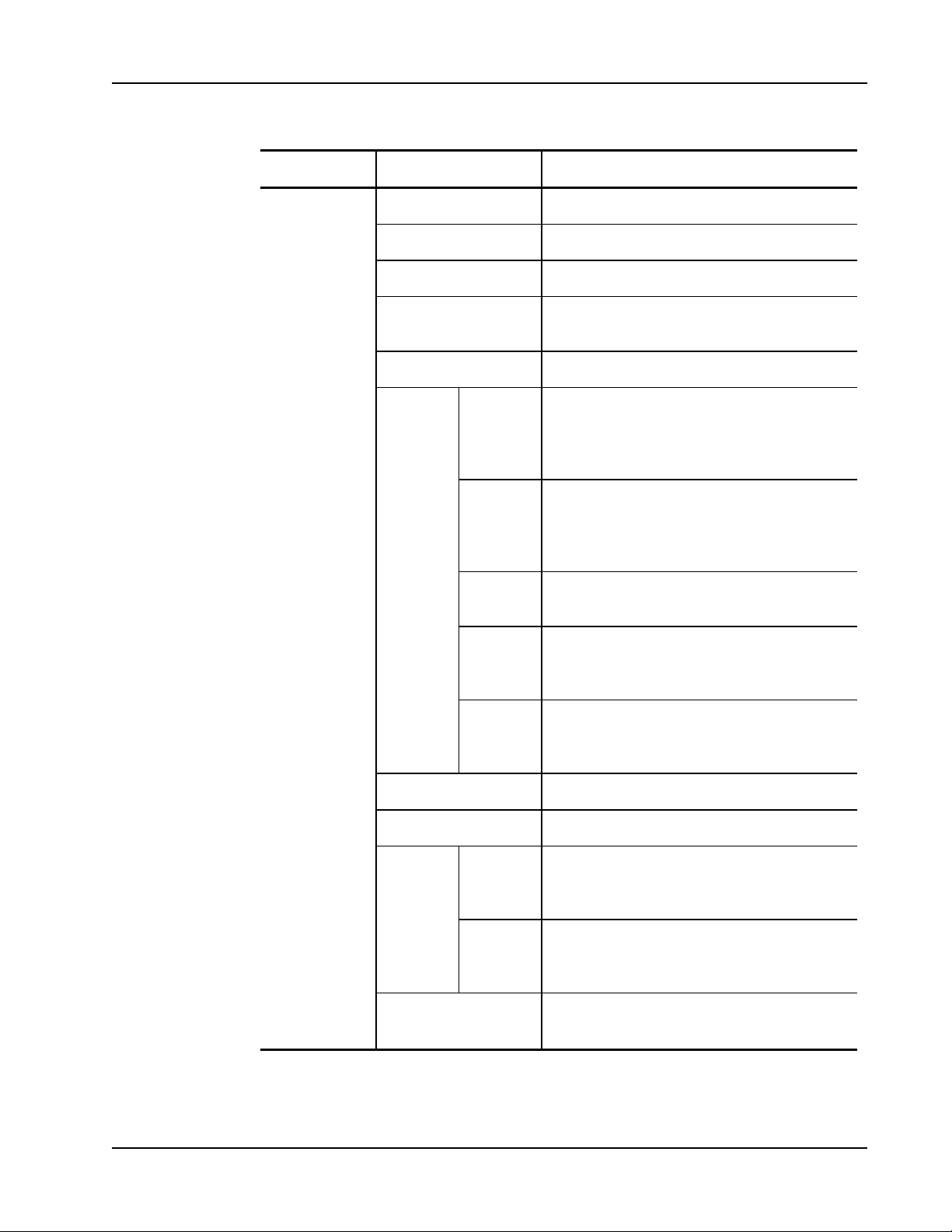
OPTIONS Logo Default / User
Logo Capture
Auto source Off / On
Navigating the Projector Menu
Input
Auto Power Off (min) 0~120
Lamp
Setting
Lamp
Hours
Used
(Normal)
Lamp
Hours
Used
(ECO)
Lamp Life
Reminder
Lamp
Power
Mode
Clear
Lamp
Hours
HDMI / VGA-A / VGA-B / S-Video /
COMPOSITE
Off / On
ECO / Normal / Extreme Dimming
No / Yes
Dynamic Black Off / On
High Altitude Off / On
Dust Filter
Reminder
Information Model Name / SNID / Source / Resolution /
Filters
Remind
(Hour)
Cleaning
Up
Reminder
No / Yes
Software Version / Color Space / Aspect Ratio
47
Page 48
Changing the Projector Settings
Main Menu Submenu Settings
3D AUTO / Off / On
3D Invert Off / On
3D
INTERACTIVE Interactive Settings Off / IR Camera
3D Format Frame Packing / Side-by-Side (Half) / Top and
1080p @ 24
Adjusting the 3D Settings
You can adjust the 3D settings for your projector.
3D
You can choose how the projector handles 3D images.
n Auto - select the 3D image automatically whenever an HDMI 1.4a 3D timing
identification signal is detected
n Off - turn off 3D functionality
n On - turn on 3D functionality
3D Invert
If you see a discrete or overlapping image while using DLP 3D glasses, you may need to
turn on this feature to get the best picture. This feature adjusts the left/right image sequence.
Bottom / Frame Sequential / Field Sequential
96Hz /
144Hz
3D Format
1080p @24
48
When using 3D mode, select the 3D format that matches the format used by the input
source.
n Frame Packing - supports HDMI 1.4a 3D input signals
n Side-by-Side (Half) - supports HDMI 1.4a 3D input signals
n Top and Bottom - supports HDMI 1.4a 3D input signals
n Frame Sequential - supports DLP Link 3D input signals from VGA / HDMI connector
and HQFS 3D input signals from Composite/S-video connector
n Field Sequential - supports HQFS 3D input signals from Composite/S-video connector
Use this feature to select 96 or 144 Hz refresh rate as using 3D glasses in the 1080p @ 24
frame packing.
Page 49

Recommended 3D Glasses
Mimio recommends the use of Optoma ZD301 or Optoma ZD302 3D glasses. For more
information, visit the Optoma website at
http://www.optomausa.com/accessorydetail.aspx?PC=ZD302.
Adjusting the Interactive Settings
Use this setting to turn on and off the Interactive function.
n IR Camera - the Interactive function is on
n Off - the Interactive function is off
Before turning on Interactive, unplug the mini-USB cable that connects your computer to
the projector. After turning on Interactive, plug the mini-USB cable back in.
Notes
l This feature is only available when displaying images from HDMI/VGA input.
l This feature is not available when using 3D or Dynamic Black.
The Interactive feature must be enabled in order to use MimioProjector as an interactive or
touch projector. For more information about the accessory kits used to enable interactive
and touch projector use, see MimioProjector Accessory Kits on page 58. The IR camera
must be connected to the projector before the projector is mounted.
Adjusting the Interactive Settings
Adjusting the Options
From the Options menu, you can change many of the projector settings as well as view the
projector information.
Logo
You can select the image to display on projector startup.
n Default- displays the default screen on projector startup
n User - displays an image of your choice on projector startup
See Logo Capture on page 49 for information on selecting an image.
Logo Capture
You can capture an image to display on projector startup.
Press ► to capture the image currently displayed on the screen.
Notes
l Ensure that the displayed image does not exceed the native resolution of the
projector (WXGA:1280x800).
l Logo Capture is not available when 3D is enabled.
l The aspect ratio should be set to Auto before using capturing an image.
49
Page 50

Changing the Projector Settings
Auto Source
Select how to handle searching for an input source when the projector loses signal from the
current input source.
n On - the projector searches for signals from other input sources when the current input
signal is lost
n Off - the projector searches only for a signal from the current input connection when the
current input signal is lost
Input
Use this option to select the input types that the projector will search for.
1. From the Options menu, select Input, and then press ►.
2. Select the input that you do not want the projector to search for, and then press ► to
clear the check box for the selected input type.
Auto Power Off
The projector has an auto-off feature which automatically turns the projector off when no
input signal is received by the projector for a set amount of time.
Lamp Setting
Lamp Hours Used (Normal)
Lamp Hours Used (ECO)
Lamp Life Reminder
Lamp Power Mode
You can set the amount of time the projector will stay on before automatically turning off .
1. Press Menu on the remote control.
2. Select Options.
3. Select Auto Power Off.
4. Using the arrow button adjust to the desired amount of time.
5. Press Menu to save the settings.
View the amount of time the projector has been used in normal lamp power mode.
View the amount of time the projector has been used in ECO lamp power mode.
You can choose whether or not the projector displays a warning message when the lamp is
nearing end of life.
The following lamp power modes are available:
50
n Normal - the projector lamp is at full brightness
n ECO - the projector lamp is dimmed to reduce power consumption, extending the life
of the lamp
Page 51

Clear Lamp Hours
Dynamic Black
High Altitude
Adjusting the Options
n Extreme Dimming - the projector lamp is dimmed 30 percent to reduce power
consumption, extending the life of the lamp
Reset the lamp hours counter after replacing the projector lamp.
Use Dynamic Black to display the image with the optimum contrast by automatically
providing signal compensation to suit the currently displayed image.
Notes
l This feature is only available when the color mode is set to Movie.
l This feature is not available when using 3D or Interactive.
l Lamp Power Mode cannot be used with this feature.
The fan power required varies depending on the altitude you are at. Set this option
appropriately to ensure that the projector cools properly.
Filters Remind
n On - the built-in fans automatically run at a variable speed according to the internal
temperature of the projector
n Off - the built-in fans run at high speed
Select this option when using the projector at altitudes above 5000 feet/1524 meters.
You can set a time to be reminded to perform filter maintenance.
n Filters Remind (Hour) - Set the number of hours that pass before you are reminded to
clean the dust filters. The dust filters should be cleaned after every 500 hours of use.
Clean the filters more frequently if the projector is used in a dusty environment.
n Cleaning Up Reminder - Once you have cleaned or replaced the dust filters, reset the
timer to be reminded then next time the filters require maintenance.
51
Page 52

Changing the Projector Settings
Information
Display the following projector information:
n Model name
n SNID
n Source
n Resolution
Adjusting the Picture
Many settings are available for adjusting the picture displayed by the projector..
Color Mode
The following optimized color modes are available for viewing various types of images.
n Brightest - for brightness optimization
n PC - for viewing meeting presentations
n Movie - for viewing video content
n Game - for viewing game content
n User - for storing your manually configured settings
Wall Color
Select the wall color that the image is projected onto.The projector settings automatically
adjust to show the correct image tone, compensating for color deviation due to wall color.
n Software version
n Color space
n Aspect ratio
Brightness
Contrast
Sharpness
52
Adjust the brightness of the image.
Press ◄ to darken image.
Press ► to lighten the image.
The Contrast controls the difference between the lightest and darkest parts of the picture.
Adjusting the contrast changes the amount of black and white in the image.
Press ◄ to decrease the contrast.
Press ► to increase the contrast.
Adjust the sharpness of the image.
This setting is only supported when Movie is selected as the color mode.
Press ◄ to decrease the sharpness.
Press ► to increase the sharpness.
Page 53

Saturation
Hue
Gamma
Adjusting the Screen
Adjust the color saturation of the image. The saturation ranges from black and white to fully
saturated color.
This setting is only supported when Movie is selected as the color mode.
Press ◄ to decrease the amount of saturation in the image.
Press ► to increase the amount of saturation in the image.
Adjust the red and green color balance.
This setting is only supported when Movie is selected as the color mode.
Press ◄ to increase the amount of green in the image.
Press ► to increase the amount of red in the image.
Adjusts the representation of dark scenery. The greater the gamma value, the bright dark
scenery will appear.
Press ◄ to decrease the gamma value.
Press ► to increase the gamma value.
Color Temperature
At a higher color temperature, the image appears colder; at a lower color temperature, the
image appears warmer.
Color Space
Select the appropriate color matrix type; Auto, RGB, or YUV.
Adjusting the Screen
You can adjust the screen and display settings for the projector.
Aspect Ratio
The following aspect ratios are available for scaling the projected image.
n Auto - keeps the image the original width-to-height ratio and maximizes the image to
fit native horizontal or vertical pixels
n 4:3 - scales the image to fit the screen and displays using a 4:3 ratio
n 16:9- scales the image to fit the width of the screen and adjusts the height to display
the image using a 16:9 ratio
n 16:10 - scales the image to fit the width of the screen and adjusts the height to display
the image using a 16:10 ratio
53
Page 54

Changing the Projector Settings
Phase
Change the signal timing of the display to match the timing of the graphics card for your
computer. If the image appears unstable or flickers, use this setting to correct it.
Press ◄ to decrease the signal timing.
Press ► to increase the signal timing.
Clock
Change the display data frequency to match the frequency of the graphics card for your
computer. Adjust this setting only if the image appears to flicker vertically.
Press ◄ to decrease the data frequency.
Press ► to increase the data frequency.
Horizontal Position
Adjust the horizontal position of the projected image.
The range for this setting depends on the input source.
Press ◄ to move the image left.
Press ► to move the image right.
Vertical Position
Adjust the vertical position of the projected image.
The range for this setting depends on the input source.
Press ◄ to move the image down.
Press ► to move the image up.
Digital Zoom
Use this setting to zoom the projected image.
Press ◄ to reduce the size of the image.
Press ► to magnify the image on the projection screen.
Vertical Keystone
Use this setting to adjust the vertical distortion of the image. If the image appears
trapezoidal, adjust this setting to make the image appear rectangular.
Press ◄ or ► to adjust the vertical distortion of the image.
Adjusting the General Settings
You can adjust many of the general settings for your projector.
Language
Select the language to use when displaying the projector menus.
54
Page 55
Menu Location
Closed Caption
Adjusting the General Settings
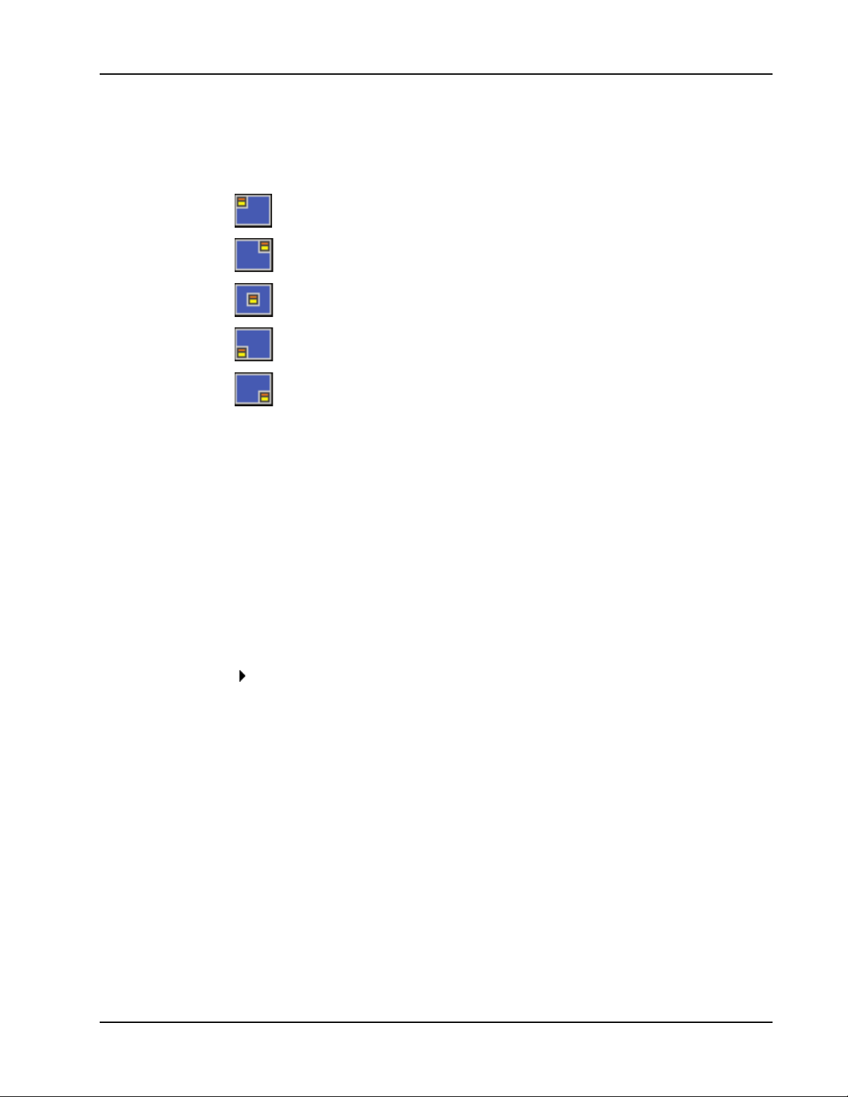
Select the location for the projector menu to display.
Top left
Top right
Center
Bottom left
Bottom right
The following closed caption options are available:
n Off
n CC1
n CC2
n CC3
n CC4.
VGA OUT (Standby)
You can enable VGA OUT connection to display the projector image on an additional
display.
Select On to enable VGA OUT connection.
Auto Screen (12V Out)
If you are using the projector with a powered screen, you can choose to automatically lower
and raise the screen when the projector is powered on and off.
n On - the screen lowers automatically when you turn the projector power on and raises
automatically when you turn the projector power off
n Off - the screen does not lower and raise automatically when you turn the projector
power on and off
55
Page 56

Changing the Projector Settings
Test Pattern
You can display a test pattern to test the image settings.
n On - show the test pattern
n Off - hide the test pattern
Security
You can choose to require a password to be entered each time the projector is turned on.
The following security settings are available:
n On - the user must enter a password in order to power on the projector
n Off - the user is not required to enter a password in order to power on the projector
Setting the Password
If the password is entered incorrectly 3 times, the projector automatically shuts down. If you
forget your password, contact Mimio Technical Support for assistance.
To set the password for the first time
1. From the Security menu, select Change Password, and then press ►.
2. Use the navigation keys to enter 000000 as the current password, and then press ►.
If the password is entered incorrectly 3 times, the projector automatically shuts
down.
3. Use the navigation keys to enter a new password, and then select ENTER to confirm.
The password must be six digits.
4. Use the navigation keys to enter the new password again, and then select ENTER to
confirm.
To change the password
1. From the Security menu, select Change Password, and then press ►.
2. Use the navigation keys to enter the current password, and then press ►.
If the password is entered incorrectly 3 times, the projector automatically shuts
down.
3. Use the navigation keys to enter a new password, and then select ENTER to confirm.
The password must be six digits.
4. Use the navigation keys to enter the new password again, and then select ENTER to
confirm.
Reset
56
Resetting the projector resets all projector settings to the factory defaults.
Select Yes to reset the projector.
Page 57

Adjusting the Volume
You can adjust the projector volume settings.
Mute
You can choose to mute the projector audio.
You can also press Mute on the remote control to turn mute on and off.
Volume
Use this setting to increase or decrease the speaker volume.
Press ◄ to decrease the volume.
Press ► to increase the volume.
You can also use the volume buttons on the remote control to adjust the volume.
Microphone Volume
Use this setting to increase or decrease the microphone volume.
Adjusting the Volume
Press ◄ to decrease the volume.
Press ► to increase the volume.
57
Page 58
MimioProjector Accessory Kits
1
2
3
4
MimioProjector Accessory
You can update your MimioProjector to an interactive projector using either the
MimioProjector 280I Interactive Accessory Kit or the MimioProjector 280T Touch
Accessory Kit.
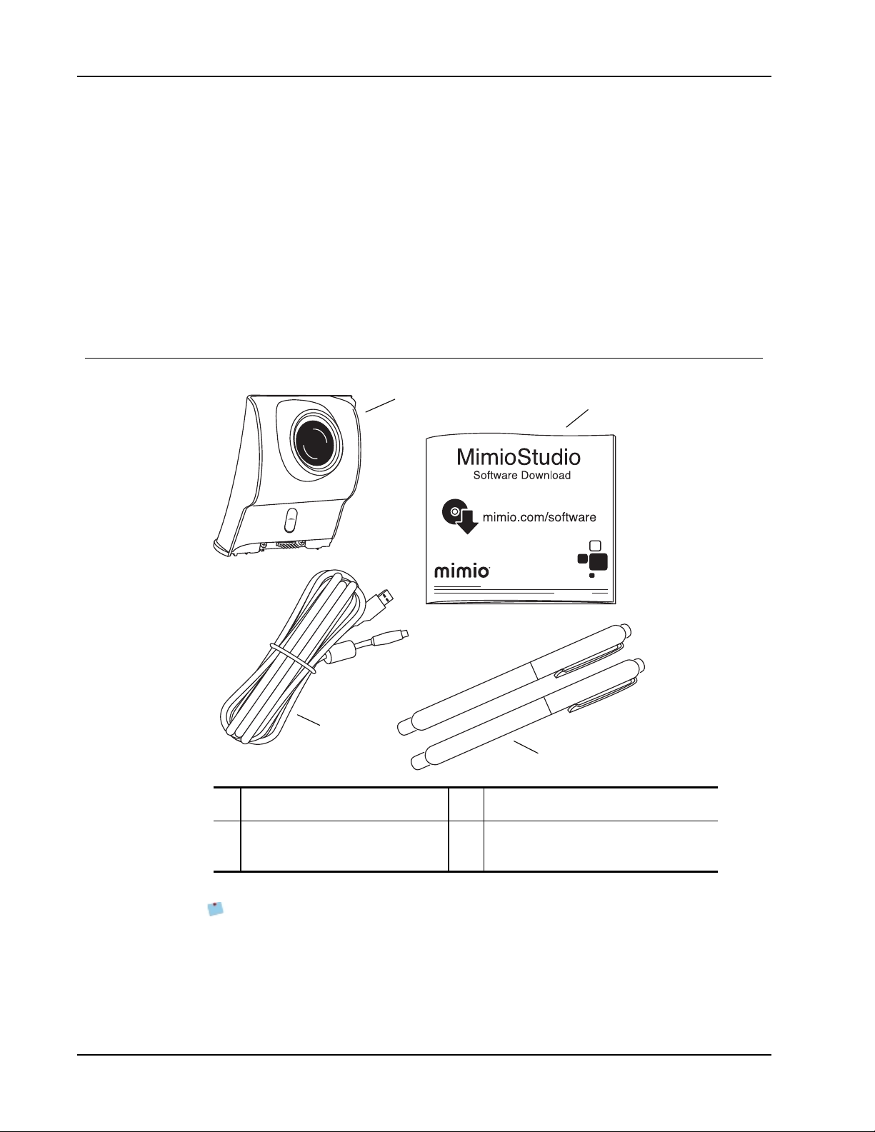
MimioProjector 280I Accessory Kit: What's Included
The MimioProjector 280I Accessory Kit includes the following items:
Kits
58
1 IRModule 3 USB cable
2 MimioStudioSoftware download
card
If you are missing any of the items above, contact Technical Support.
Pens from the MimioProjector 240 are not compatible with the MimioProjector 280I.
MimioProjector 240 pens have a white clip with the Mimio logo engraved;
MimioProjector 280I pens have a silver clip with no logo.
4 Pens (x2)
Page 59
MimioProjector 280T: What's Included
x
2
x
2
1
5
6
7
2
4
3
8
9
10
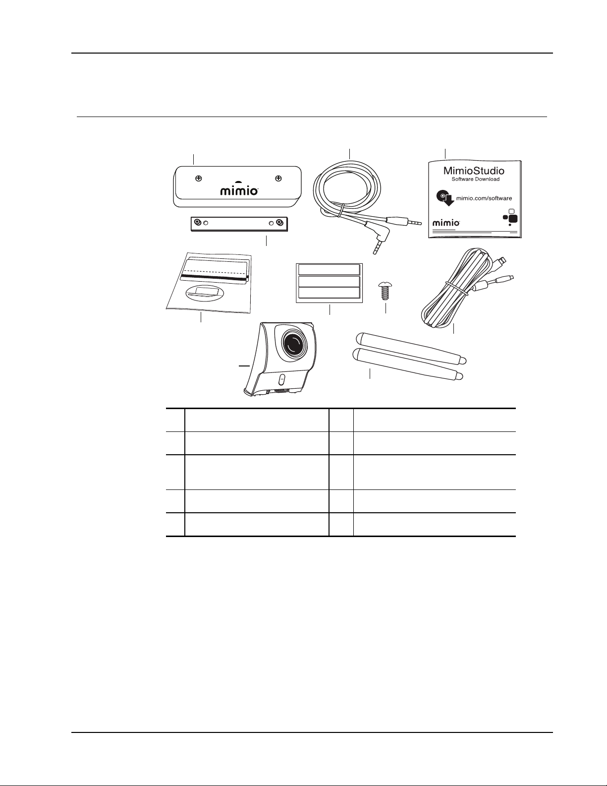
The MimioProjector 280T Accessory Kit includes the following items:
MimioProjector 280T: What's Included
1 Laser curtain module 6 3M double-sided tape
2 Power cord 7 Screws
MimioStudio Software download
3
card
8 USBcable
4 Laser curtain mounting bracket 9 IR module
5 Alignment stickers 10 Styli (x2)
If you are missing any of the items above, contact Technical Support.
59
Page 60
MimioProjector Accessory Kits
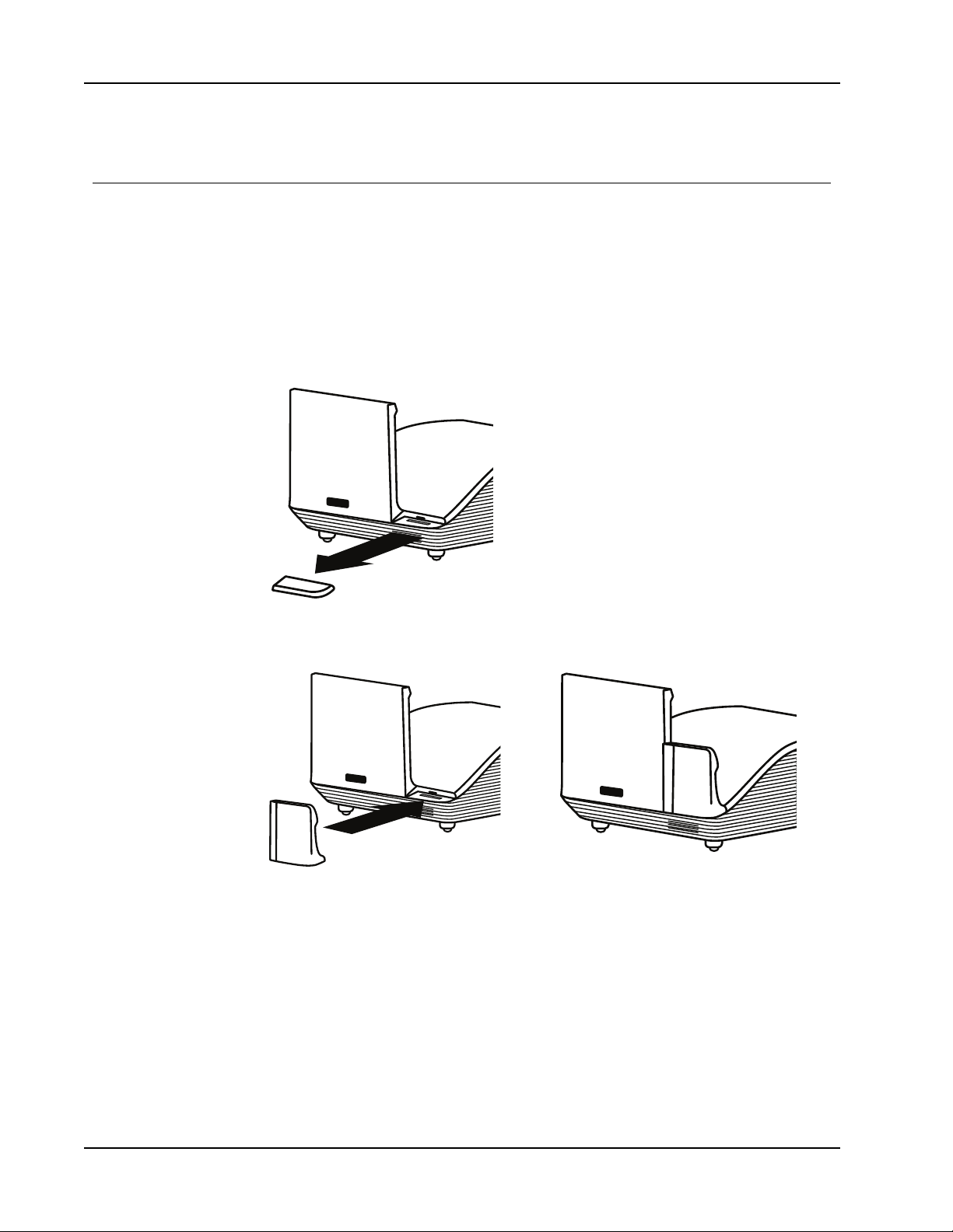
Connecting the IRModule
You can update your MimioProjector to an interactive projector for pens using the
IRmodule included in the MimioProjector 280I or for touch using the IR module included
with the MimioProjector 280T Accessory Kit.
Once the IRmodule is connected, you will need to turn on the Interactive function in the
projector settings. For information about turning this feature on, see Adjusting the
Interactive Settings on page 49.
To connect the IR module
1. Slide the IR module connector cover from the projector.
2. Align the IRmodule with the IRmodule connector on the projector and slide into
place.
60
Page 61
Installing the Laser Curtain
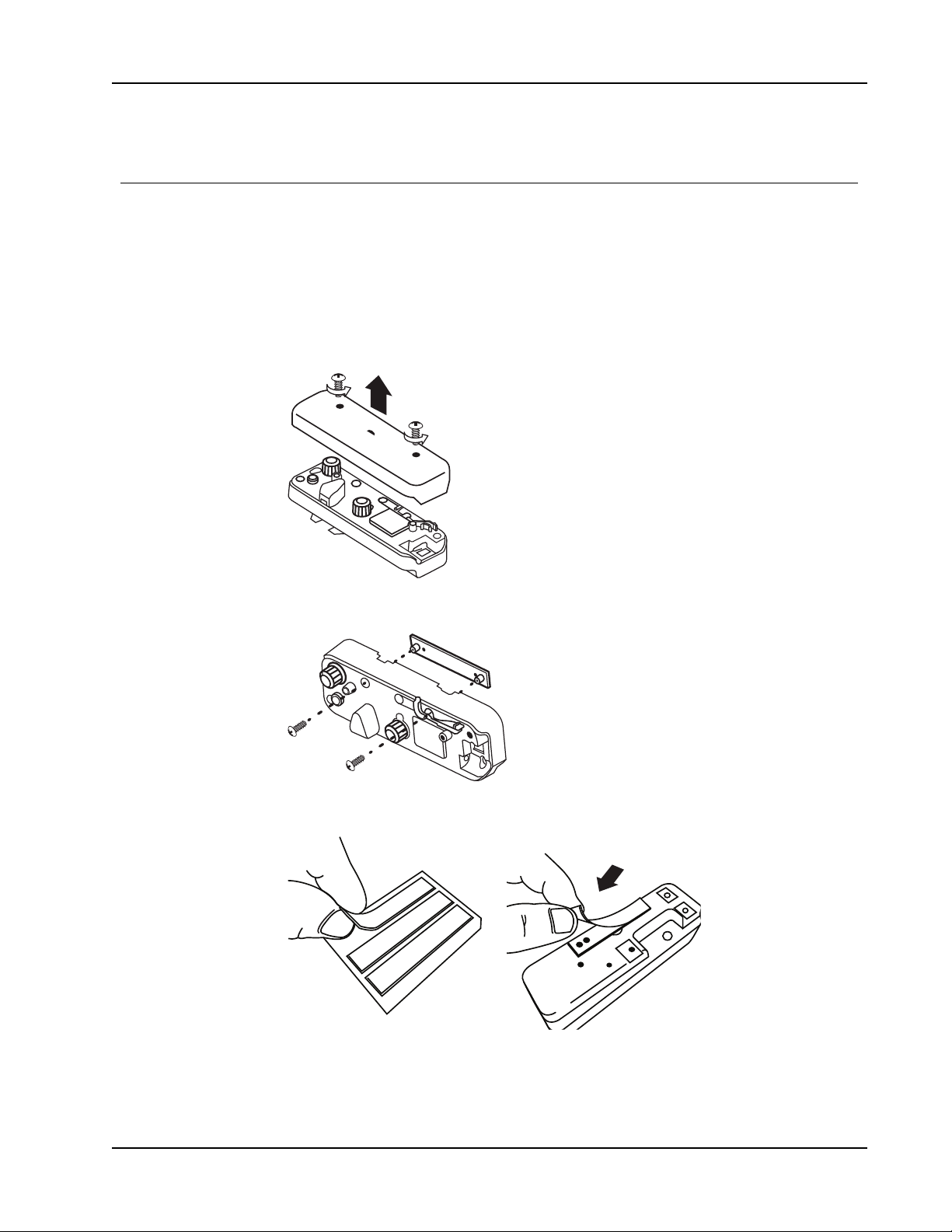
You can update your MimioProjector to a touch projector using the laser curtain and IR
modules.
Once the laser curtain module is installed and the IRmodule is connected, you will need to
turn on the Interactive function in the projector settings. For information about turning this
feature on, see Adjusting the Interactive Settings on page 49.
To install the laser curtain
1. Using a crosshead screwdriver, remove the screws from the laser curtain module and
remove the top cover of the module.
Installing the Laser Curtain
2. Attach the mounting bracket to the back of the laser curtain module using the included
screws.
3. Affix one piece of 3M double-sided tape (included) onto the back of the mounting
bracket as shown, and the remove the paper backing from the tape.
61
Page 62
MimioProjector Accessory Kits
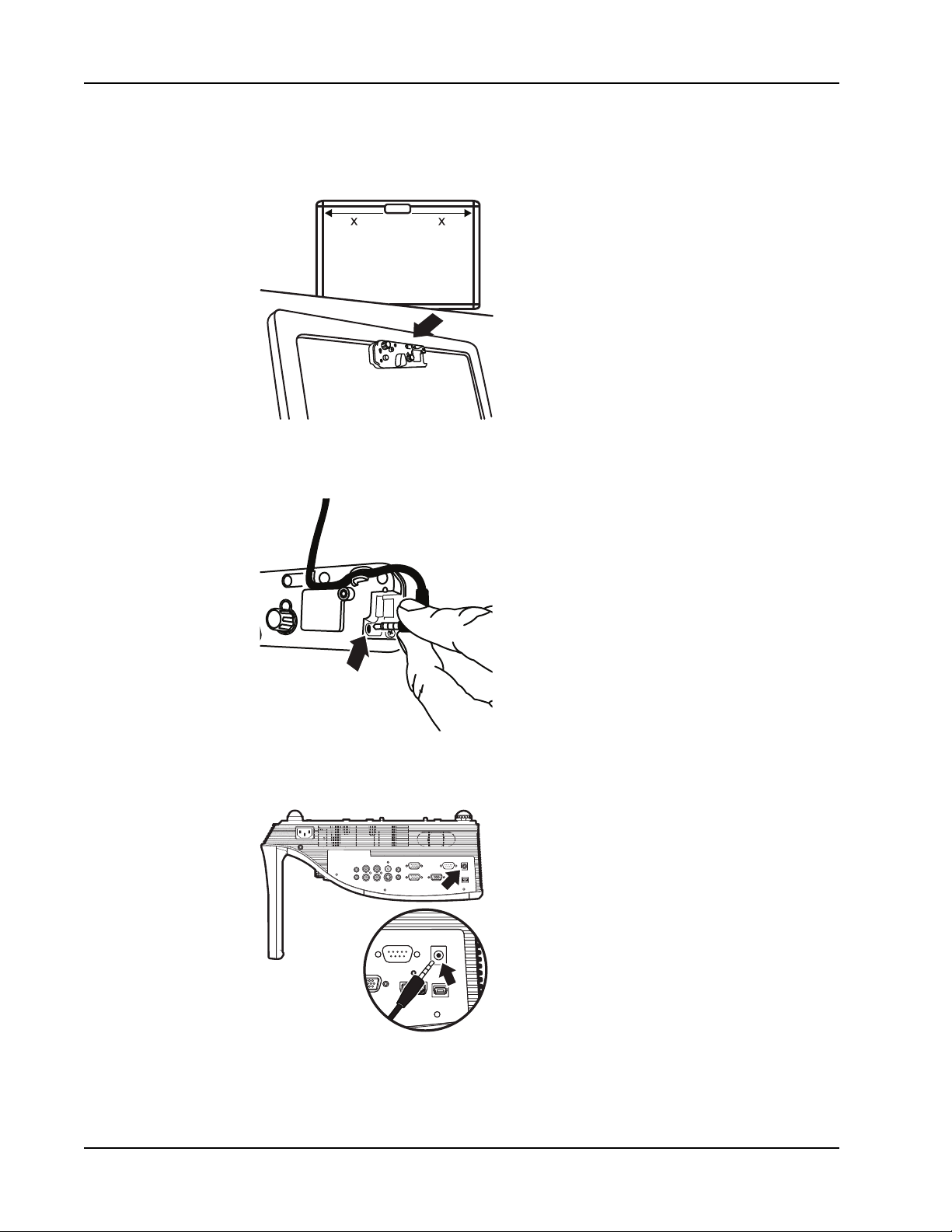
x = x
4. Place the laser curtain module at the top of the board, centered with the projector lens,
and press in place.
5. Plug the power cord into the power connector on the laser curtain module and run the
cord through the cableway.
62
6. Plug the other end of the laser curtain power cord into the DC Out 12V port on the side
of the projector.
7. Turn on the projector.
A blue light on the laser curtain will illuminate.
Page 63
Installing the Laser Curtain
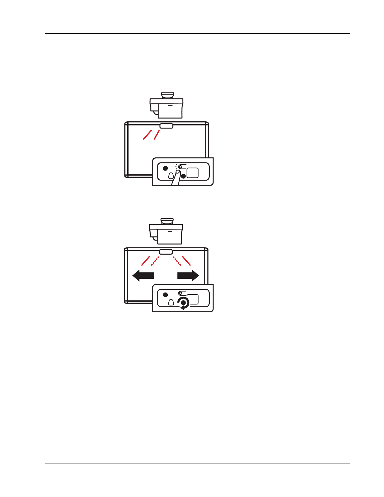
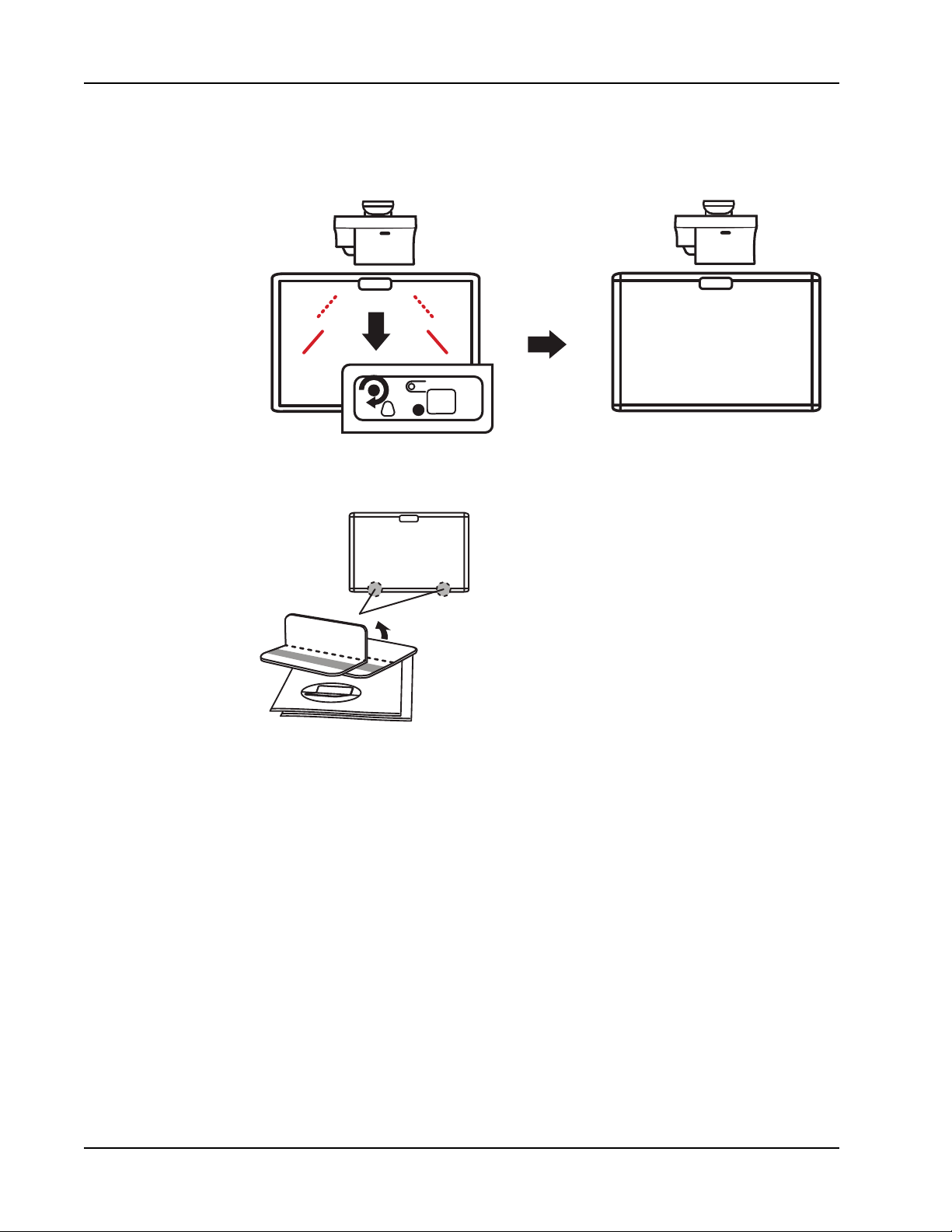
8. To align the laser curtain, press the button above the blue light.
The blue light will turn red and flash indicating two laser beams are visible for
alignment.
9. Turn the gray knob on the laser curtain module clockwise until the two red laser marks
are centered on the board.
63
Page 64
MimioProjector Accessory Kits
10. Turn the black knob on the laser curtain module clockwise, lowering the laser marks,
until the two laser marks are no longer visible on the board.
11. Fold one alignment sticker as shown and affix the sticker to the bottom-left edge of the
board.
64
A red laser mark should appear on the alignment sticker.
12. Fold the other alignment sticker and affix the sticker to the bottom-right edge of the
board.
A red laser mark should appear on the alignment sticker.
Page 65
Installing the Laser Curtain
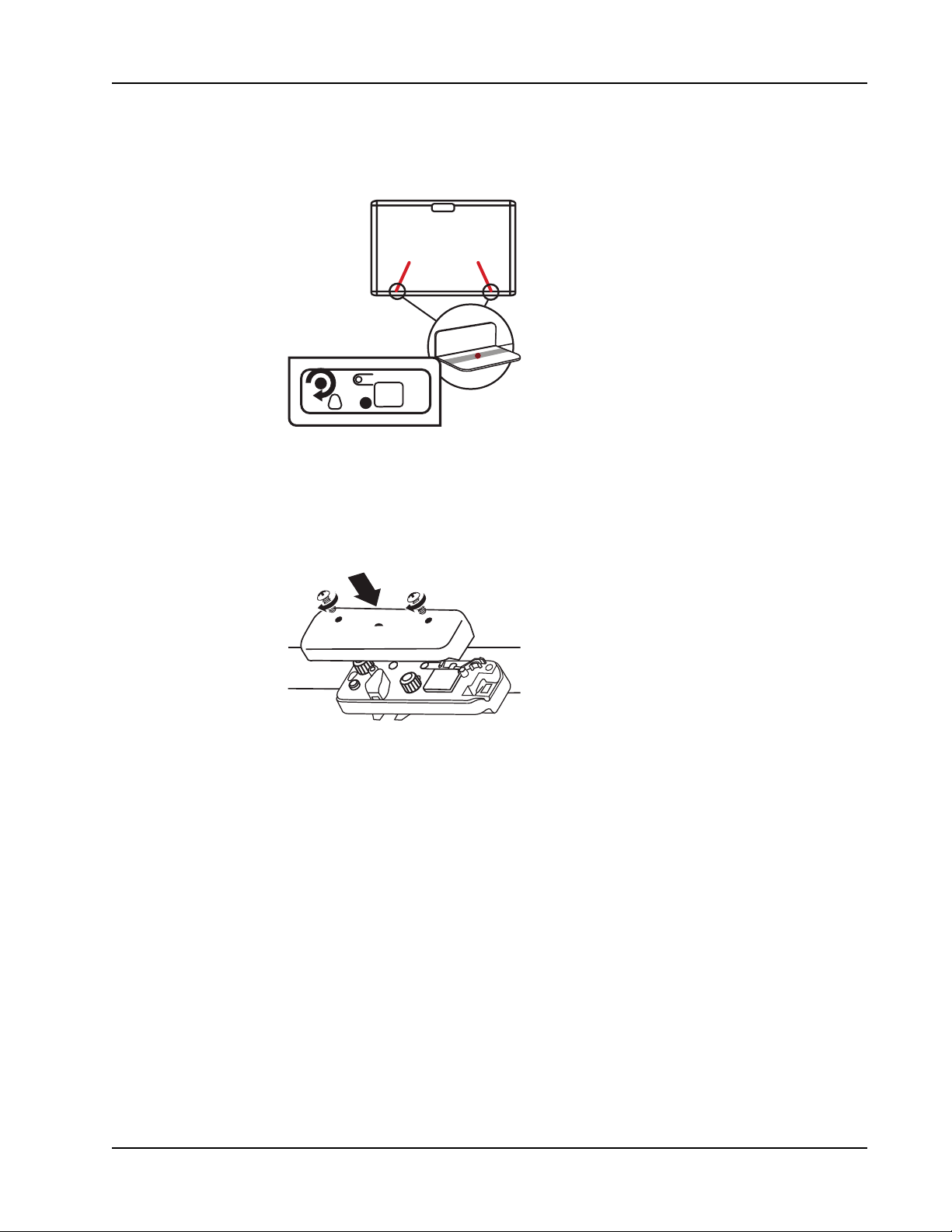
13. Turn the black knob on the laser curtain module clockwise until the red laser marks are
visible in the gray strip area of each alignment sticker.
14. Once both lasers are aligned on the alignment stickers, press the button above the
bliniking red light on the laser curtain module.
The light turns blue, indicating you are in touch mode.
15. Place the laser curtain module cover back on the laser curtain module and replace the
screws using a crosshead screwdriver.
65
Page 66
Caring for MimioProjector
3
V
O
L
T
S
CR2025
Caring for MimioProjector
Replacing the Remote Control Battery
To ensure safe operation, please observe the following precautions :
n Use only CR2025 type battery.
Using the incorrect battery type may cause explosion.
n Avoid contact with water or liquid.
n Do not expose the remote control to moisture or heat.
n Do not drop the remote control.
n If the battery leaks while inserted in the remote control, carefully wipe the case clean
and install new battery.
n Dispose of used battery according to battery instructions.
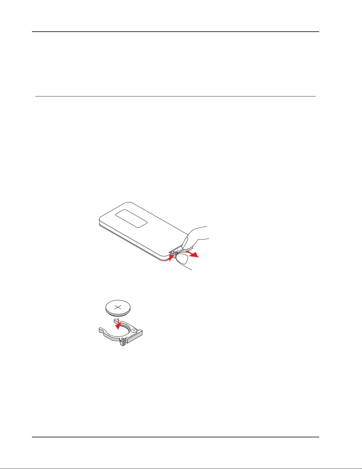
To replace the battery
1. Press firmly and slide the battery holder out of the battery compartment.
2. Remove the old battery from the battery holder.
3. Insert a new battery into the battery holder with the + polarity marking facing up as
shown.
66
Page 67
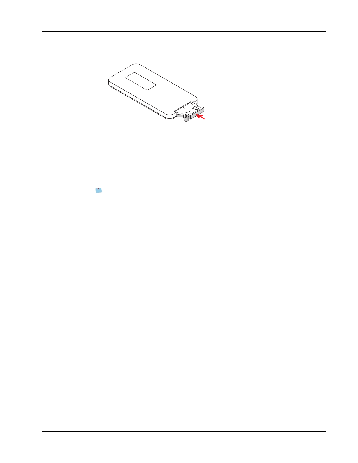
4. Slide the battery holder back into the battery compartment and press firmly.
M
3
V
O
L
T
S
CR2025
Replacing the Lamp
The projector automatically detects the lamp life. When the lamp is nearing the end of life,
a warning is displayed on the screen.
When the warning appears, contact Mimio Technical Support to order a replacement lamp
as soon as possible. Make sure the projector is off and has cooled down for at least 60
minutes before changing the lamp.
Notes
l MimioProjector uses an OSRAM P-VIP 280/0.9 E20.9 bulb.
l The screws on the lamp cover and the lamp cannot be removed.
l The projector cannot be turned on while the lamp cover is removed.
l Do not touch the glass area of the lamp. Oils from your skin can cause the lamp to
shatter. Use a dry cloth to clean the lamp module if the lamp is accidentally
touched.
To remove the lamp module
1. Press the power button to turn off the projector.
2. Allow the projector to cool down for at least 60 minutes.
3. Unplug the power cord.
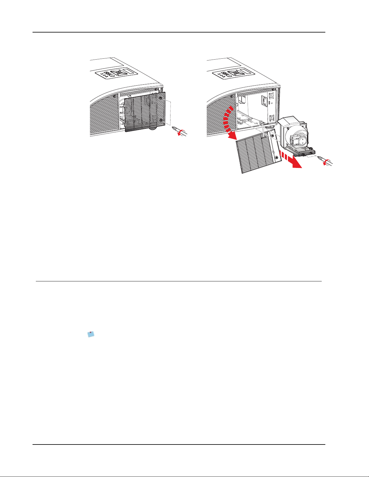
4. Using a screwdriver, loosen the two screws on the lamp cover.
5. Lift and remove the lamp cover.
6. Using a screwdriver, loosen the two screws on the lamp module.
7. Pull the lamp handle up and slowly and carefully remove the lamp module.
Replacing the Lamp
67
Page 68
Caring for MimioProjector
To insert the new lamp module
1. Slowly and carefully slide the lamp module into the lamp compartment (do not force)
2. Using a screwdriver, tighten the two screws on the lamp module.
3. Replace the lamp cover.
4. Using a screwdriver, tighten the two screws on the lamp cover.
5. Plug the power cord into a wall outlet.
6. Press the power button to turn on the projector.
7. Clear the lamp hours. See Clear Lamp Hours on page 51 for information about
and push the lamp handle down.
clearing the lamp hours.
Cleaning the Dust Filters
The dust filters should be cleaned after every 500 hours of use. Clean the filters more
frequently if the projector is used in a dusty environment.
When the dust filters need to be cleaned, a warning is displayed on the screen.
When the warning appears, clean the dust filters as soon as possible. Make sure the
projector is off before cleaning the dust filters.
Notes
l The dust filters should be used in dusty environments.
l Properly maintaining the dust filters prevents overheating of the projector and
related damage.
To clean the dust filters
1. Press the power button to turn off the projector.
2. Unplug the power cord.
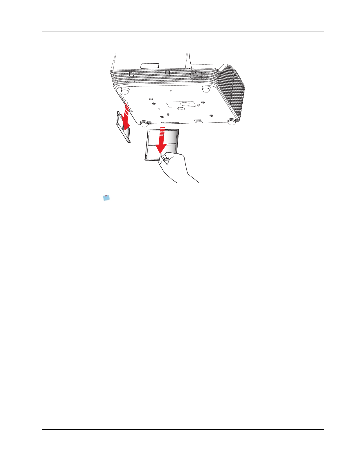
3. Pull the latch and slowly and carefully remove the dust filters from the projector.
68
Page 69
Cleaning the Dust Filters
4. Use a vacuum to clean the dust filters.
Do not wash filters. Filters do not need to be replaced.
5. Slide the dust filters back into the projector.
6. Plug the power cord into a wall outlet.
7. Press the power button to turn on the projector.
8. Reset the filter maintenance reminder.
See Filters Remind on page 51 for information about resetting the filters reminder.
69
Page 70
Getting Help
POWER TEMP LAMP
Status Lights
Getting Help
Review this chapter if you encounter a problem with your projector.
If you are unable to solve a problem, this chapter also describes how to contact Mimio
Technical Support.
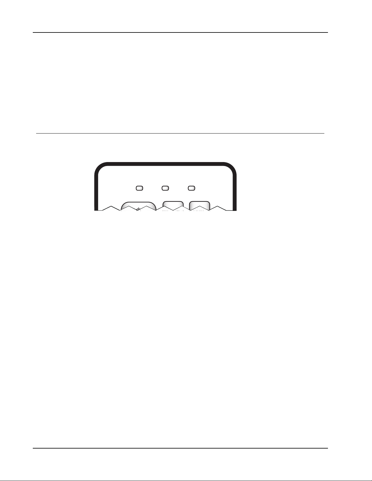
The status lights on the projector control panel visually show the status of the
MimioProjector.
70
Page 71

General Troubleshooting
Message
Power Plug
Standby On Off Off Off
Power button ON Off On Off Off
Cooling state
Power button OFF; Cooling completed;
Standby Mode
Firmwar e Download On On On On
Thermal Switch error (lamp over
temperature);
OSD shows "Projector Overheated"
Thermal sensor error (system over
temperature);
OSDshowes "Projector Overheated"
POWER TEMP LAMP
Red Blue Red Red
Flash ON/OFF
100ms
0.5 sec (ON)
0.5 sec (OFF)
flashing
On Off Off Off
Off On Off On
Off On Off On
Off
Off Off Off
Flash ON/OFF
100ms
Flash ON/OFF
100ms
Fan lock error OSD shows red "Fan Fail,
Will automatically turn off soon"
Lamp error (Lamp, ballast) Off On Off On
Color wheel fail
Photo sensor f ail
Off On Off
Off On Off
General Troubleshooting
Review this section if you encounter a general problem with your projector.
Projector stops responding to all controls
1. Press the power button to turn the projector off.
2. Unplug the power cord.
3. After 20 seconds, or longer, plug the power cord back in.
4. Press the power button to turn the projector on.
Lamp burns out or makes a popping sound
When the lamp reaches end of life, it burns out and may make a loud popping sound. The
projector will not turn on again until the lamp module is replaced. For information about
replacing the lamp, see Replacing the Lamp on page 67.
0.5 sec (ON)
0.5 sec (OFF)
flashing
0.5 sec (OFF)
flashing
71
Page 72

Getting Help
Image Troubleshooting
No image is displayed
n Ensure all cables and power connections are correctly and securely connected as
described in Connecting the Projector on page 39.
n Ensure the pins of connectors are straight and not broken.
n Ensure that the projection lamp is securely installed. For more information, refer to
Status Lights on page 70.
n Ensure that the Blank feature is not activated. See About the Remote Control on page
12 for more information about the Blank feature.
72
Page 73

A partial, scrolling, or incorrect image is displayed
n Press ReSync on the remote control or on the projector control panel.
If you are using a computer as the input source, do the following:
1. Verify that the display resolution setting for your computer is set at 1080p or lower.
Refer to the documentation for your computer for information about changing the
display resolution for your computer.
If you experience difficulty changing resolutions or the PC monitor freezes, restart
all equipment including the projector.
2. If you are using a notebook computer, press the keyboard buttons needed to toggle the
output setting.
Notebook Brand Function Keys
Acer [Fn]+[F5]
Asus [Fn]+[F8]
Dell [Fn]+[F8]
Gateway [Fn]+[F4]
IBM/Lenovo [Fn]+[F7]
HP/Compaq [Fn]+[F4]
NEC [Fn]+[F3]
Toshiba [Fn]+[F5]
Mac Apple System Preference -> Display -> Arrangement -> Mirror display
Image Troubleshooting
The notebook computer display is not displaying an image
Some notebook computers may deactivate the screens when a second display device is in
use. Each has a different way to be reactivated. Refer to the documentation for your
computer for detailed information.
Image is unstable or flickering
n Adjust the Phase setting on the projector. See Phase on page 54 for information about
changing the Phase setting.
n Change the monitor color setting on your computer.
Image has vertical flickering bar
n Adjust the Clock setting on the projector. to make an adjustment. See Clock on page
54 for information about changing the Clock setting.
n Check and reconfigure the display mode of your graphic card to make it compatible
with the projector.
Image is out of focus
n Adjust the focus ring on the projector lens.
n Make sure the projection screen is within the required distance.
73
Page 74

Getting Help
Image is stretched when displaying 16:9 DVD image
n When you play anamorphic DVD or 16:9 DVD, the best image is displayed when the
projector is set to use 16: 9 format.
If the image is still stretched, verify that the format setting on your DVD player is set
correctly.
Image is too small or too large
n Move the projector closer to or further from the screen.
n Adjust the aspect ratio setting on the projector. See Aspect Ratio on page 53 for
information about adjusting the aspect ratio.
Image is displayed with slanted sides
n If possible, reposition the projector so that the image is centered on the screen.
n Adjust the vertical keystone setting on the projector. See Vertical Keystone on page 54
for information about adjusting this setting.
Image is reversed
Verify that the ceiling mount setting on the projector is set correctly. See Adjusting the
Screen on page 53for information about adjusting this setting.
3D Troubleshooting
Two images are displayed side-by-side
Set the 3D format to Side-by-Side (Half). For information about changing the 3D format, see
3D Format on page 48.
Image not displayed in 3D
n Make sure your 3D glasses are powered on.
n Make sure the batteries in the 3D glasses have sufficient charge.
n Set the 3D format to Side-by-Side (Half).
For information about changing the 3D format, see 3D Format on page 48.
Sound Troubleshooting
n If you are playing sound only or with video from an external source, make sure you
have the audio cable securely connected to the source device and the audio input on
the projector.
n Make sure the volume is not set to the minimum on the source and the projector.
n Make sure the Mute feature is off.
74
Page 75
Remote Control Troubleshooting
n Make sure the operating angle of the remote control is within ±30° both horizontally
and vertically of one of the IR receivers on the projector.
n Make sure there are no obstructions between the remote control and the projector.
n Move to within 7 m (±0°) of the projector.
n Make sure the battery is inserted correctly.
n Replace the battery.
Contacting Mimio
Mimio maintains an Internet Web site that offers support for MimioClassroom products. In
addition, Mimio’s Technical Support department is available by phone.
Web site: www.mimio.com
Phone: (877) 846-3721
Mimio Technical Support is available from 9am - 5pm ET, Monday through Friday.
Remote Control Troubleshooting
When calling Mimio Technical Support, please have your product serial number available.
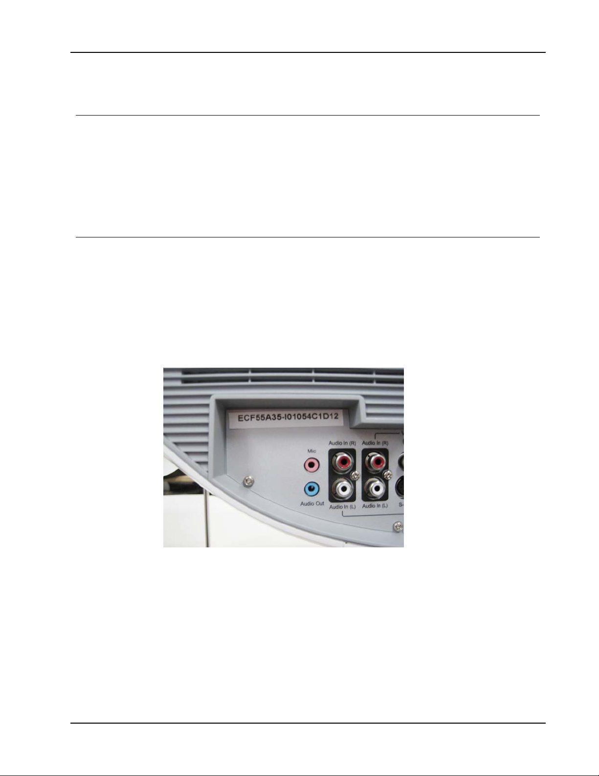
The serial number for your MimioProjector is located near the input/output connection ports
on the back of your projector.
Visit the Support section of our Web site at www.mimio.com to contact us by email.
75
Page 76
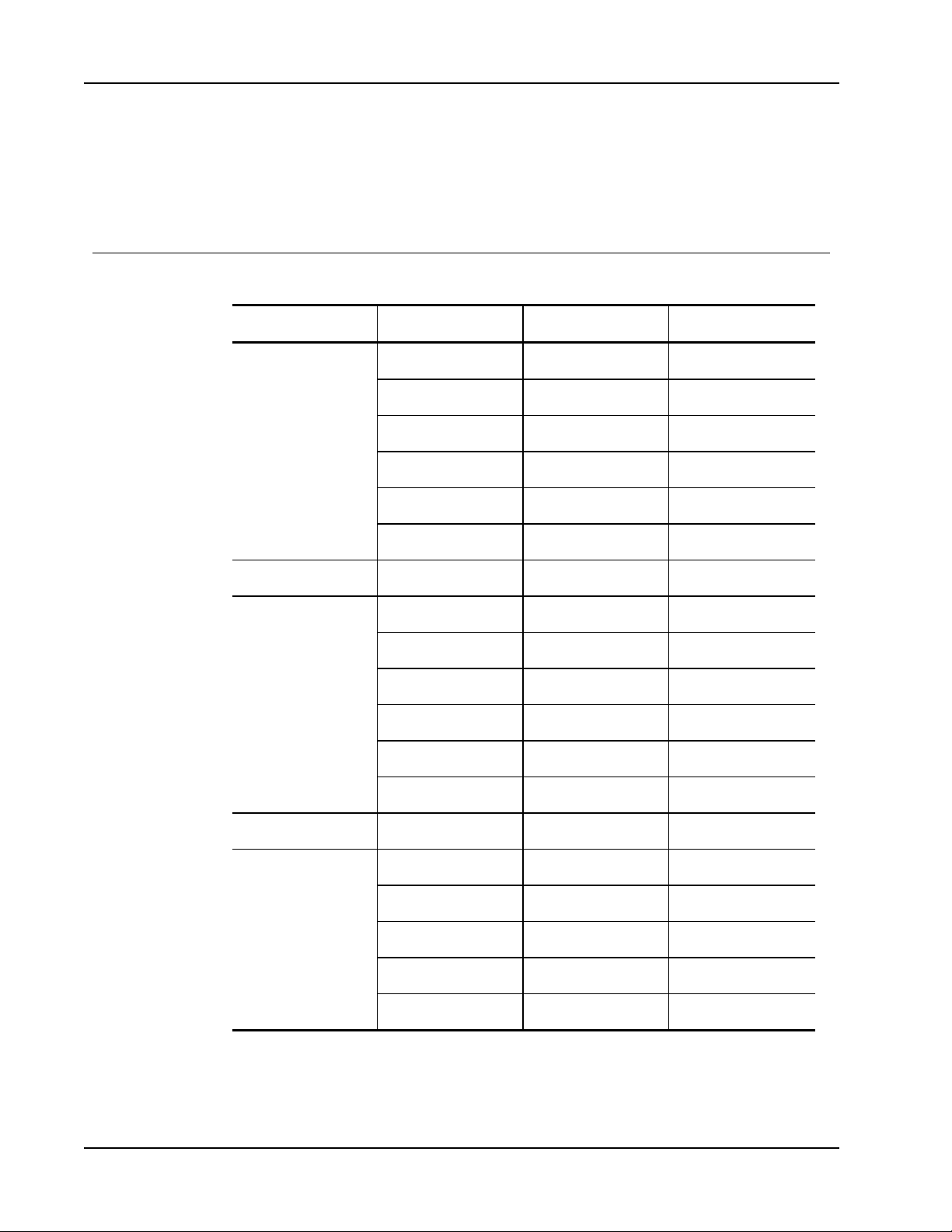
Compatibility Modes
VGA Analog
PC Signal
Compatibility Modes
Modes Resolution V. Frequency [Hz] H. Frequency [Hz]
VGA 640x480 60 31.5
640x480 67 35.0
640x480 72 37.9
640x480 75 37.5
640x480 85 43.3
640x480 120 61.9
IBM 720x400 70 31.5
SVGA 800x600 56 35.1
800x600 60 37.9
800x600 72 48.1
800x600 75 46.9
800x600 85 53.7
800x600 120 77.4
Apple, MAC II 832x624 75 49.1
XGA 1024x768 60 48.4
1024x768 70 56.5
1024x768 75 60.0
1024x768 85 68.7
76
1024x768 120 99.0
Page 77
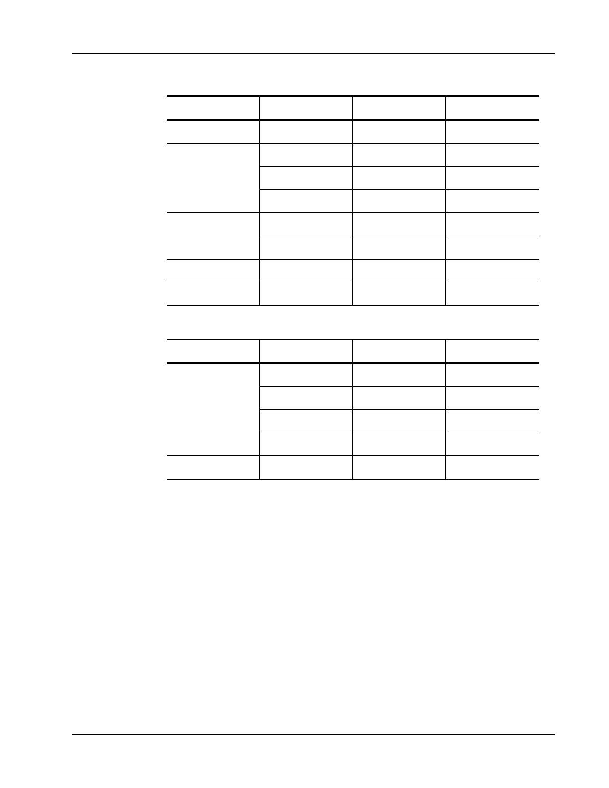
Modes Resolution V. Frequency [Hz] H. Frequency [Hz]
Apple, MAC II 1152x870 75 68.7
SXGA 1280x1024 60 64.0
QuadVGA 1280x960 60 60.0
SXGA+ 1400x1050 60 65.3
UXGA 1600x1200 60 75.0
Extended Wide Timing
VGA Analog
1280x1024 72 77.0
1280x1024 75 80.0
1280x960 75 75.2
Modes Resolution V. Frequency [Hz] H. Frequency [Hz]
WXGA 1280x720 60 44.8
1280x800 60 49.6
1366x768 60 47.7
1440x900 60 59.9
WSXGA+ 1680x1050 60 65.3
77
Page 78
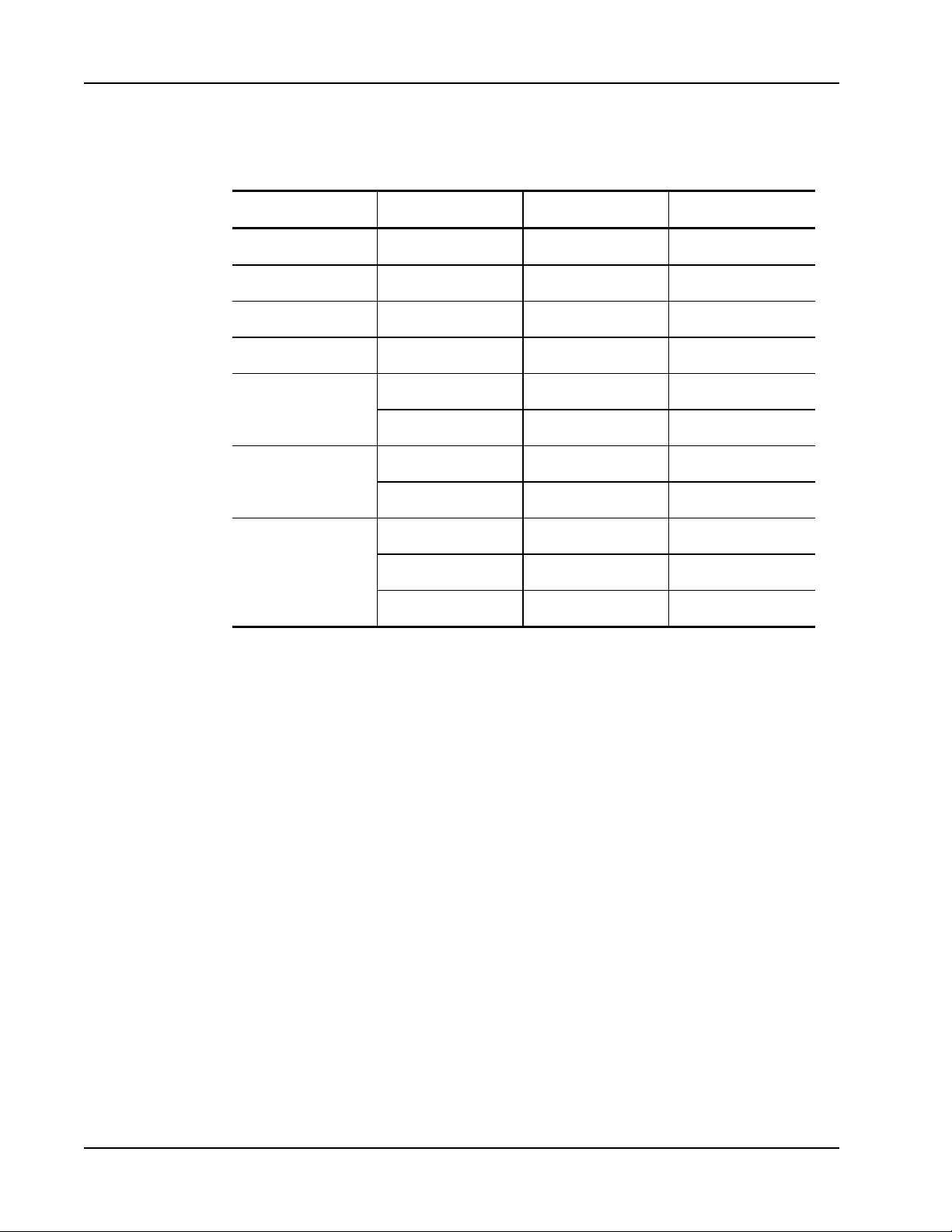
Compatibility Modes
Component Signal
Modes Resolution V. Frequency [Hz] H. Frequency [Hz]
480i 720x480(1440x480) 59.94(29.97) 15.7
576i 720x576(1440x576) 50(25) 15.6
480p 720x480 59.94 31.5
576p 720x576 50 31.3
720p 1280x720 60 45.0
1080i 1920x1080 60(30) 33.8
1280x720 50 37.5
1920x1080 50(25) 28.1
1080p 1920x1080 23.98/24 27.0
1920x1080 60 67.5
1920x1080 50 56.3
78
Page 79
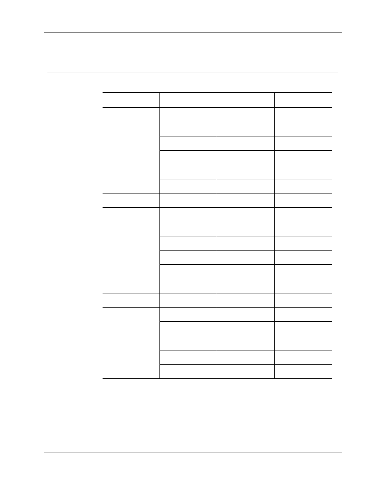
HDMI Digital
PC Signal
HDMI Digital
Modes Resolution V. Frequency [Hz] H. Frequency [Hz]
VGA 640x480 60 31.5
640x480 67 35.0
640x480 72 37.9
640x480 75 37.5
640x480 85 43.3
640x480 120 61.9
IBM 720x400 70 31.5
SVGA 800x600 56 35.1
800x600 60 37.9
800x600 72 48.1
800x600 75 46.9
800x600 85 53.7
800x600 120 77.4
Apple, MAC II 832x624 75 49.1
XGA 1024x768 60 48.4
1024x768 70 56.5
1024x768 75 60.0
1024x768 85 68.7
1024x768 120 99.0
79
Page 80
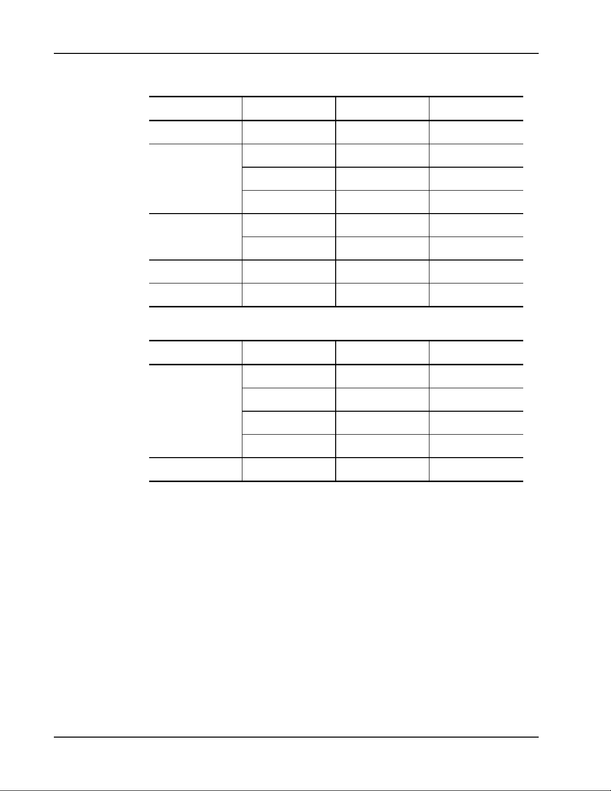
Compatibility Modes
Modes Resolution V. Frequency [Hz] H. Frequency [Hz]
Apple, MAC II 1152x870 75 68.7
SXGA 1280x1024 60 64.0
QuadVGA 1280x960 60 60.0
SXGA+ 1400x1050 60 65.3
UXGA 1600x1200 60 75.0
Extended Wide Timing
1280x1024 72 77.0
1280x1024 75 80.0
1280x960 75 75.2
Modes Resolution V. Frequency [Hz] H. Frequency [Hz]
WXGA 1280x720 60 44.8
1280x800 60 49.6
1366x768 60 47.7
1440x900 60 59.9
WSXGA+ 1680x1050 60 65.3
80
Page 81
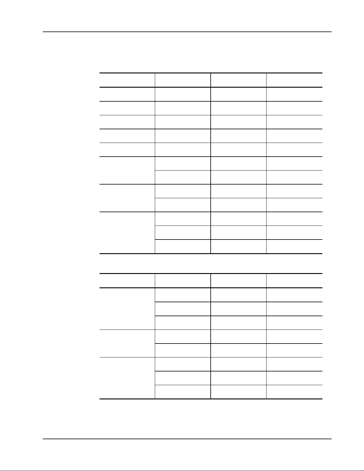
Video Signal
HDMI Digital
Modes Resolution V. Frequency [Hz] H. Frequency [Hz]
480p 640x480 59.94/60 31.5
480i 720x480(1440x480) 59.94(29.97) 15.7
576i 720x576(1440x576) 50(25) 15.6
480p 720x480 59.94 31.5
576p 720x576 50 31.3
720p 1280x720 60 45.0
1280x720 50 37.5
1080i 1920x1080 60(30) 33.8
1920x1080 50(25) 28.1
1080p 1920x1080 23.98/24 27.0
1920x1080 60 67.5
1920x1080 50 56.3
HDMI 1.4a Mandatory 3D Timing - Video Signal
Modes Resolution V. Frequency [Hz] H. Frequency [Hz]
Frame Packing 720p 50 31.5
720p 59.94/60 15.7
1080p 23.98/24 15.6
Side-by-Side(Half) 1080i 50 31.5
1080i 59.94/60 31.3
Top and Bottom 720p 50 45.0
720p 59.94/60 37.5
1080p 23.98/24 33.8
81
Page 82

Technical and Environmental Information
Environmental Information
This chapter contains technical information for the MimioProjector.
For product specifications and compliance information, visit the Documentation section of
the Support area of our Web site at www.mimio.com.
Usage Notice
Follow all warnings, precautions, and maintenance as recommended in this user guide.
Warnings
n Do not look into the projector lens when the lamp is on. The bright light may hurt and
damage your eyes.
n To avoid the risk of fire or electric shock, do not expose the projector to rain or
moisture.
n Do not open or disassemble the projector as this may cause electric shock.
n When replacing the lamp, allow the unit to cool down first. Follow the instructions as
described under Replacing the Lamp on page 67.
n The projector has a timer to track the life of the lamp. Be sure to replace the lamp when
the projector displays the lamp warning message.
n After replacing the projector lamp, reset the lamp hours setting. See Clear Lamp Hours
on page 51 for information about resetting the lamp hours.
n When turning the projector power off, ensure that the cooling cycle completes before
disconnecting the power. Allow 10 seconds for the projector to cool down.
n Do not block the light path between the light source and the lens with any object.
Doing so could cause the object to catch on fire.
n Do not look into or point the laser pointer from the laser curtain module into any
person's eyes. Laser pointers can cause permanent damage to eyesight.
Technical and
Precautions
82
n Turn off and unplug the power plug from the AC outlet before cleaning the product.
n Use a soft damp cloth with mild detergent to clean the display housing.
n Disconnect the power plug from the AC outlet if the product is not being used for a
long period of time.
n Use a soft dry cloth to clean the lens if needed. Be sure the projector has been turned
off and allowed to cool.
Page 83

Do not do the following
n Block the ventilation slots and openings on the unit.
n Use abrasive cleaners, waxes, or solvents to clean the unit.
n Use under the following conditions:
l In extremely hot, cold, or humid environments.
l Ensure that the ambient room temperature is between 5°C - 40°C (41°F - 104°F).
l Ensure relative humidity is a maximum of 80%, non-condensing.
l In areas susceptible to excessive dust and dirt.
l In direct sunlight.
Regulation & Safety Notices
This section lists the general notices of your projector.
FCC Notice
This device has been tested and found to comply with the limits for a Class B digital device
pursuant to Part 15 of the FCC rules. These limits are designed to provide reasonable
protection against harmful interference in a residential installation. This device generates,
uses and can radiate radio frequency energy and, if not installed and used in accordance
with the instructions, may cause harmful interference to radio communications.
Regulation & Safety Notices
However, there is no guarantee that interference will not occur in a particular installation. If
this device does cause harmful interference to radio or television reception, which can be
determined by turning the device off and on, the user is encouraged to try to correct the
interference by one or more of the following measures:
n Reorient or relocate the receiving antenna.
n Increase the separation between the device and receiver.
n Connect the device into an outlet on a circuit different from that to which the receiver
is connected.
n Consult the dealer or an experienced radio/television technician for help.
Notice
Shielded cables all connections to other computing devices must be made using shielded
cables to maintain compliance with FCC regulations.
Caution
Changes or modifications not expressly approved by the manufacturer could void the user’s
authority, which is granted by the Federal Communications Commission, to operate this
projector.
Operating Conditions
This device complies with Part 15 of the FCC Rules. Operation is subject to the following
two conditions:
83
Page 84

Technical and Environmental Information
1. This device may not cause harmful interference and
2. This device must accept any interference received, including interference that may cause
undesired operation.
Notice: Canadian Users
This Class B digital apparatus complies with Canadian ICES-003.
Remarque à L’intention des Utilisateurs Canadiens
Cet appareil numerique de la classe B est conforme a la norme NMB-003 du Canada.
Declaration of Conformity for EU countries
n EMC Directive 2004/108/EC (including amendments)
n Low Voltage Directive 2006/95/EC
n R & TTE Directive 1999/5/EC (if product has RF function)
Projector Mount Safety Notices
Read these warnings carefully and use the product as intended.
n The manufacturer shall not be legally responsible for any equipment damage or personal
injury caused by incorrect installation or operation.
n The wall mount is designed for easy installation and removal. The manufacturer shall
not be liable for damage to equipment or personal injuries arising from human factors or
acts of God, such as earthquake or typhoon.
n The wall mount must be installed by professional personnel only.
n To avoid any hazard caused by falling objects, a minimum of two persons are needed to
install or remove the wall mount.
n Maintain ample space around the projector to ensure good ventilation.
n To ensure safety and avoid any accident, investigate the structure of the wall and select
an appropriate and durable location for the product before installing.
n The wall must have load-carrying capability to sustain more than four times the total
weight of the projector and the wall mount.
n Check the areas around the installation location carefully.
l Do not install the product in an area subject to high temperature, humidity, or
contact with water.
l Do not install the product in a location subject to dust or fumes.
l Do not install the product on slanted surfaces; install only on vertical walls.
l Do not install the product in an area subject to vibrations or shocks.
l Do not install the product in an area subject to direct exposure to bright light; doing
so may cause eye fatigue when viewing the projected image.
n Do not modify any accessory or use broken parts. Contact Mimio Technical Support
with any questions.
n Tighten all screws, but do not apply excessive torque to any screw. Excessive torque
may break or damage the screw or screw threads.
84
Page 85

n The wall mount is rated for a maximum load of 15 Kg (33 Ibs.).
n Do not hang or place any objects on the wall mount other than the projector.
Documentation Feedback
We are constantly working to produce the highest quality documentation for our products.
We welcome your feedback. Send us your comments or suggestions about our online Help,
printed, or PDF manuals.
Please include the following information with your feedback:
n Product name and version number (if applicable)
n Type of document: printed manual, PDF, or online Help
n Topic title (for online Help) or page number (for printed or PDF manuals)
n Brief description of content (for example, step-by-step instructions that are inaccurate,
information that requires clarification, areas where more detail is needed, and so on)
n Suggestions for how to correct or improve the documentation
We also welcome your suggestions for additional topics you would like to see covered in
the documentation.
Documentation Feedback
Send email feedback to:
Please keep in mind that this email address is only for documentation feedback. If you have
a technical question, please contact Mimio Technical Support.
85
 Loading...