

Page 1
MIMAKI ENGINEERING CO., LTD.
https://mimaki.com/
D202217-21
Page 2

TABLE OF CONTENTS
CAUTION ......................................................................... vi
DISCLAIMER OF WARRANTY........................................vi
Requests ..........................................................................vi
FCC Statement (USA)......................................................vi
Interference to televisions and radios...............................vi
CDRH REGULATION......................................................vii
Foreword .........................................................................viii
On this operation manual ...............................................viii
For safe operation ............................................................ ix
Symbols............................................................................ix
Position of the warning label............................................ xv
How to Read This Operation Manual .............................xvii
CHAPTER 1 Before Use
Installing the machine..............................................1-2
Where to install the machine......................................1-2
Moving this machine ..................................................1-3
Configuration and Function .....................................1-4
Front...........................................................................1-4
Rear ...........................................................................1-4
Operation Panel.........................................................1-5
Carriage .....................................................................1-6
EMERGENCY SWITCH.............................................1-6
Connecting the cables.............................................1-7
Connecting the USB2.0 interface cable.....................1-7
Connecting the power cable.......................................1-7
Setting of ink cartridge.............................................1-8
Kinds of ink that can be used.....................................1-8
About Media ..........................................................1-10
The sizes of media that can be used .......................1-10
Precautions in handling the media...........................1-10
Menu mode ...........................................................1-11
CHAPTER 2 Basic Operations
Operation flow .........................................................2-2
Turning the power ON.............................................2-3
Setting the media ....................................................2-4
Set the media in another method...............................2-5
Test drawing............................................................2-6
Execution of head cleaning .....................................2-8
Drawing an image from source data........................2-9
i
Page 3

Starting the drawing operation...................................2-9
Interruption of drawing.............................................2-10
Checking drawing data that is being received or has been
received...................................................................2-10
When [! WORK High] is displayed........................... 2-11
If you open the cover during drawing ......................2-11
Turning the power OFF......................................... 2-12
CHAPTER 3 Useful Function
Changing origin....................................................... 3-2
Changing origin with JOG keys.................................3-2
Changing origin with FUNCTION menu ....................3-3
Setting the Head Height.......................................... 3-4
Setting the media thickness.......................................3-4
Setting the head gap .................................................3-5
Setting the table height..............................................3-6
Gap check .................................................................3-7
Perform setting to reduce stripes between passes. 3-8
Other useful functions........................................... 3-10
Data clear................................................................3-10
Displaying information of this machine....................3-10
Proceed with drawing that you suspended..............3-11
Alternative nozzles for printing, when nozzles missing can not
be improved ...................................................................... 3-12
Checking ink landing displacement.........................3-14
Various settings .................................................... 3-15
Setting the print method ..........................................3-15
Setting the mode of the LED UV .............................3-16
Increasing cumulative UV irradiation when the number of
passes is low...........................................................3-17
Setting of priority......................................................3-18
Setting the mode of the fan mode ...........................3-19
Setting the work change..........................................3-20
Setting the ink weight ..............................................3-21
Changing language display on the screen ..............3-22
Output the setting list...............................................3-23
Displaying machine information............................... 3-24
Other useful settings................................................3-26
Initializing settings ...................................................3-27
Setting time..............................................................3-28
Setting mm/ inch......................................................3-29
ii
Page 4

Setting weight of the empty cartridge.......................3-30
Setting Key buzzer...................................................3-31
Setting radiator pump...............................................3-32
Setting the flushing level before printing..................3-33
CHAPTER 4 Maintenance
Routine maintenance...............................................4-2
When this machine is left unused for a long time.......4-2
Precautions in cleaning..............................................4-2
Cleaning exterior surfaces .........................................4-3
Cleaning the table......................................................4-3
Ink cartridge.............................................................4-4
Replacing with a new ink cartridge.............................4-4
Setting the ink set.......................................................4-5
Ink cartridge trouble ...................................................4-8
Shaking the white ink cartridge..................................4-9
600ml Ink cartridge................................................4-10
Registering the case weight.....................................4-10
Registering the cartridge weight...............................4-11
Registering the cartridge weight (After LVL LOW / LVL
END) ........................................................................4-12
Avoiding dripping of ink droplet at printing.............4-13
When the waste ink is full......................................4-15
Disposing of the ink in the waste ink tank................4-15
Disposing of the waste ink in the wiper bottle..........4-17
Replacing the Filter................................................4-19
Washing the Nozzle...............................................4-21
Wash the ink discharge passage...........................4-23
When the Machine Is Not Used for a Long Time (CUS-
TODY WASH)........................................................4-25
Washing the Head.................................................4-27
Perform ink filling...................................................4-29
Setting nozzle face cleaning time..........................4-30
Regular maintenance for white ink........................4-31
iii
Cleaning of wiper...................................................4-33
Refilling antifreeze mixed water.............................4-35
Refilling antifreeze mixed water...............................4-36
Page 5

CHAPTER 5 In Case of Trouble
Before taking a phenomenon as a trouble.............. 5-2
The machine cannot be energized............................5-2
The machine cannot perform printing........................5-2
If image quality declines............................................5-3
Resolving nozzle clogging.........................................5-3
When the ink leakage occurs ....................................5-3
Troubles for which error messages are given on the
LCD......................................................................... 5-4
Warning Message......................................................5-4
Error message...........................................................5-6
CHAPTER 6 Appendix
Specifications.......................................................... 6-2
Basic unit specifications ............................................6-2
Specifications for ink..................................................6-3
Function Flowchart.................................................. 6-5
iv
Page 6

CAUTION
DISCLAIMER OF WARRANTY
THIS LIMITED WARRANTY OF MIMAKI SHALL BE THE SOLE AND EXCLUSIVE WARRANTY AND IS IN LIEU
OF ALL OTHER WARRANTIES, EXPRESS OR IMPLIED, INCLUDING, BUT NOT LIMITED TO, ANY IMPLIED
WARRANTY OF MERCHANTABILITY OR FITNESS, AND MIMAKI NEITHER ASSUMES NOR AUTHORIZES
DEALER TO ASSUME FOR IT ANY OTHER OBLIGATION OR LIABILITY OR MAKE ANY OTHER WARRANTY
OR MAKE ANY OTHER WARRANTY IN CONNECTION WITH ANY PRODUCT WITHOUT MIMAKI’S PRIOR
WRITTEN CONSENT.
IN NO EVENT SHALL MIMAKI BE LIABLE FOR SPECIAL, INCIDNETAL OR CONSEQUENTIAL DAMAGES OR
FOR LOSS OF PROFITS OF DEALER OR CUSTOMERS OF ANY PRODUCT .
Requests
• This Operation Manual has been carefully prepared for your easy understanding, however, please do not
hesitate to contact a distributor in your district or our office if you have any inquiry.
• Description contained in this Operation Manual are subject to change without notice for improvement.
FCC Statement (USA)
This equipment has been tested and found to comply with the limits for a Class A digital device, pursuant to Part
15 of the FCC Rules. These limits are designed to provide reasonable protection against harmful interference
when the equipment is operated in a commercial environment. This equipment generates, uses and can radiate
radio frequency energy and, if not installed and used in accordance with the operation manual, may cause
harmful interference to radio communications.
Operation of this equipment in a residential area is likely to cause harmful interference in which cause the user
will be required to correct the interference at his own expense.
• In the case where MIMAKI-recommended cable is not used for connection of this device, limits provided
by FCC rules can be exceeded. To prevent this, use of MIMAKI-recommended cable is essential for the
connection of this machine.
Interference to televisions and radios
The product described in this manual generates low radio wave s while it is in operation. T he product can interfere
with radios and televisions if set up or commissioned under improper conditions. The product is not guaranteed
against any damage to specific-purpose radios and televisions.
The product’s interference with your radio or television will be checked by turning on/off the power switch of the
product.
In the event that the product is the cause of interference, try to eliminate it by taking one of the following
corrective measures or taking some of them in combination.
• Change the direction of the receiving antenna or the feeder of your radio/television.
• Move the receiver away from the product.
• Plug the power cord of this machine into an outlet which is isolated from power circuits connected to the television
set or radio.
vi
Page 7

CAUTION
CDRH REGULATION
The Center for Devices and Radiological Health for the U.S. Food and Drug Administration Implement
regulations for laser products. The sentence of “This product complies with 21 CFR chapter I and subchapter J”
indicates compliance with the CDRH regulations and is labeled on the product when marketed in the United
States. This Model is equivalent to Class II laser device according to CDRH Regulation.
This product complies with 21 CFR chapter I and subchapter J
• Use of controls, adjustments or performance of procedures other than those specified in this manual
may results in hazardous radiation exposure.
vii
Page 8

Foreword
Congratulations on your purchase of a MIMAKI "UJF-3042FX" model of UV ink jet printer.
UV Inkjet Printer UJF-3042FX uses ultraviolet ray curing ink (UV ink).
Read this Operation Manual carefully and make the most effective use of your printer.
On this operation manual
• This Operation Manual describes the operation and maintenance of Model UJF-3042FX Color Ink Jet Printer
(hereinafter referred to as the machine).
• Please read and fully understand this Operation Manual before putting the machine into service. It is also
necessary to keep this Operation Manual on hand.
• Make arrangements to deliver this Operation Manual to the person in charge of the operation of this machine.
• This Operation Manual has been carefully prepared for your easy understanding, however, please do not hesitate
to contact a distributor in your district or our office if you have any inquiry.
• Description contained in this Operation Manual are subject to change without notice for improvement.
• In the case where this Operation Manual should be illegible due to destruction or lost by fire or breakage,
purchase another copy of the Operation Manual from our office.
• You can also download the latest operation manual from our website.
viii
Reproduction of this manual is strictly prohibited.
© 2015 MIMAKI ENGINEERING CO., LTD.
Page 9
For safe operation
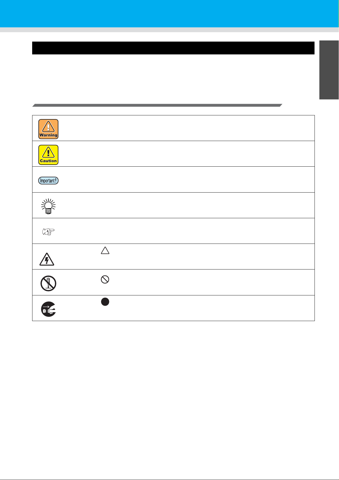
Symbols
Symbols are used in this Operation Manual for safe operation and for prevention of damage to the machine.
The indicated sign is different depending on the content of caution.
Symbols and their meanings are given below. Please follow these instructions as you read this manual.
Examples of symbols
Failure to observe the instructions given with this symbol can result in death or serious injuries to
personnel. Be sure to read it carefully and use it properly.
Failure to observe the instructions given with this symbol can result in injuries to personnel or
damage to property.
Important notes in use of this machine are given with this symbol. Understand the notes
thoroughly to operate the machine properly.
Useful information is given with this symbol. Refer to the information to operate the machine
properly.
Indicates the reference page for related contents.
The symbol “ “ indicates that the instructions must be observed as strictly as the CAUTION
instructions (including DANGER and WARNING instructions). A sign representing a precaution
(the sign shown at left warns of hazardous voltage) is shown in the triangle.
The symbol “ " indicates that the action shown is prohibited. A sign representing a prohibited
action (the sign shown at left prohibits disassembly) is shown in or around the circle.
The symbol “ " indicates that the action shown must be taken without fail or the instructions
must be observed without fail. A sign representing a particular instruction (the sign shown at left
instructs to unplug the cable from the wall outlet) is shown in the circle.
ix
Page 10

• Be sure to setup the appropriate a ir-moving system in ca se of using this machi ne in a closed room or a room
with bad ventilation.
Cautions for constructing exhaust outlet
Please observe the following cautions to avoid breakdown of this machine.
(1) The opening area of the exhaust outlet requires more than half of the duct entrance area.
(2) If mounting a valve on the exhaust outlet, be sure to open the valve when using the machine.
• The ink used for this machine falls into the category of UN No.3082 and UN Class 9. Since the ink is
flammable, never use fire when using the machine.
• When cleaning the in k station or the head, be sure to wear the suppli ed gogg le and gloves si nce you may ge t
ink or cleaning solution in your eyes.
• If anyone swallows ink or cleaning solution in mistake, get the person to vomit and see a doctor imme diately.
Do not let him or her swallow the vomit. Then, refer SDS about the inquiry.
• If you inhale a lot of vapo r and feel bad, immediately move to a location of fresh air and then keep yoursel f
warm and quiet. Then, consult a doctor as soon as possible.
• Discard the waste ink according to the local regulations of the area that this machine is used.
Never do the following
WARNING
WARNING
Do not disassemble or remodel the machine Handling of ink cartridges
• Never disassemble or remodel this machine and
the ink cartridge.
Disassembling or remodeling any of them will
result in electric shocks or breakdown of this
machine.
Do not use this machine in damp places
• Avoid damp environment to use this machine.
Do not splash water onto this machine. High
humidity or water will give rise to fire, electric
shocks or breakdown of this machine.
Abnormal event occurs
• If the machine is used under an abnormal
condition where the machine produces smoke
or unpleasant smell, fire or electric shocks can
result. Be sure to turn off the power switch
immediately and detach the plug from the
receptacle. Check first to be sure that the
machine no longer produces smoke, and
contact a distributor in your district for repair.
• Never repair your machine by yourself since it is
very dangerous for you to do so.
• Some of the ingredients (UV Curing initiator)
have toxic consequences to aquatic life. Avoid
leak into water system or sewage containing
water.
• Store ink cartridges and waste ink tank in a
place that is out of the reach of children.
• If ink settles on the skin or clothes, immed iately
wash it off with detergent or water. If you get ink
in your eyes, immediately wash your eyes with a
lot of clean water, and then consult a doctor as
soon as possible.
• In case of ink leakage, plea se turn off the main
power, unplug the power cable and contact our
service office or distributor.
x
Page 11
Wearing protective devices
• When cleaning the suction nozzle, which may scatter ink, be sure to wear safety glasses and gloves, or ink and
cleaning solution might enter your eyes or ink and clean ing solution pu t on your ha nds mig ht make yo ur ha nds
rough.
Power supply and voltage
• Use this machine with indicated power spec ifications.
Be sure to connect the power cable plug to the grounded outlet, or it may cause fire or electric shock.
• Never look at the LED UV being lit with your naked eyes, or it may cause pain in your eyes or visual impairment.
Be sure to wear safety glasses.
• Do not apply ultraviolet (UV) light directly to your skin, or it may cause irritation on your skin.
• To prevent electrical shock, be sure to set OFF the main power circuit breaker and disconnect the power plug
before carrying out maintenance. For some units, capacitors may take one minute for discharging; therefore,
start maintenance work three minutes after setting OFF the main power circuit bre aker and disconnecting the
power plug.
• If LED UV has been damaged, you should replace the LED UV that has reached or has past its rating life.
• The main power circuit breaker should be set ON only by personnel with sufficient knowledge about operati ons
of this machine.
• Do not touch the lamp with bare hands while lighting or right after the lamp off to avoid from burn injury.
Handling of the antifreeze liquid
• Use the exclusive antifreeze liquid, or the cooli ng device may be damaged.
• If the antifreeze liquid or mixed soft water wi th antifreeze l iqu id gets on th e skin or cl othes, immedia tely wash i t
off with soap.
If you get the antifreeze liquid in your eyes, immediately wash your eyes with a lot of clean water. Then, consult
a doctor as soon as possible.
• Before using the antifreeze liquid, be sure to read the Safety Data Sheet (SDS).
• If you swallowed the antifreeze liquid accide ntally, try to get to vomit, and then consult a doctor as soon as
possible.
• Discard the waste antifree ze liquid or used mixed soft water with antifreeze liquid as follows;
Absorb in a sawdust or waste cloth, then incinerate it.
• Entrust to an industrial waste disposal contractor, clarifying their contents.
• Avoid causing ignition with static electricity, impact spark and so on.
• Be sure to wear goggles and gloves for handling the antifreeze liquid.
For safe operation
WARNING
Handling of the power cable
• Use a power cable attached to this machine.
• Take care not to damage, break or work on the power cable. If a heavy things are put on the power cable,
heated or drawn, the power cable can break to cause fire or electric shocks.
Handling of LED UV
• Do not use the LED UV in an ambience with a possibility of catching fire (gasoline, comb ustible gas spray,
thinner, lacquer , powder dust, etc.). In addition, do not put paper or cloth near or on the LED UV, or it may cause
fire, or it may cause electrical shock.
Keep children away
• Keep children away from this machine.
xi
Page 12
Precautions for use
CAUTION
Protection against dust Periodic exchange parts
• It is strongly recommended to use the machine
in a room that is not dusty.
Set the Refresh level 2 or 3 when in bad
environment.
• When leaving the work place after the working
hours, be sure to remove media from the
printer.If any media is left on the printer, dust
can put on it.
• Store media not to put dust on it. Wiping dust off
the media, dust will be put on the media due to
static electricity .
• Due to the dust on the head, ink drops will fall
down on the media during printing. If so, be sure
to clean up the head. ( P.2-8)
Adjusting the level
Handling of cleaning solution
Warning labels Handling the antifreeze liquid
• Warning labels are adhered on this machine.
Be sure to fully understand the warnings given
on the labels. In the case where any of the
warning label has become so soiled that the
warning message is illegible or has come off,
purchase a new one from your local distributor
or our office.
Ink cartridges
• If the ink cartridge is moved from a cold pla ce to
a warm place, leave it in a place of use for three
hours or more and use it.
• Open the ink cartridge just before installing.
Leaving it open for a long time will cause
abnormal printing.
• Be sure to store ink cartridges in a cold and dark
place.
• Once the ink opened, be sure to use ink up
early. The ink passed for a long time after
opening the cartridge will lower the printing
quality.
UV light Hot parts
• A little UV light spills around the LED UV unit.
UV light applied to your skin might cause
inflammation and/or skin cancer.
Even weak UV light causing no inflammation
may lead to chronic disorders by repeated
exposure. Avoid applying UV light to your skin
and eyes.
• Impairment of eyes caused by UV light may be
acute disorders, pain in eyes, tearing, chronic
disorders, cataract, etc.
When using this machine, protect your body
such as gloves, long-sleeve cloth, light-resistant
mask, attached light-resistant glasses, etc.
• There are some parts which must be periodically
replaced. Contract with distributors or dealers
for maintenance.
• Keep this machine hori zontal.
• Be sure to store the cleaning solution in a cold
and dark place. Store the cleaning solution in a
place that is out of the reach of children.
• Be sure to store the antifreeze liquid in a cold
and dark place.
• Store the antifreeze liquid in a place that is ou t
of the reach of children.
• Using other than exclusive ink will break this
machine. In this case, repairing of this machine
is your responsibility.
• Never refill the ink cartridge with ink.
• Do not pound the ink cartridge nor shake it
violently. If so, ink may leak out of the cartridge.
• The LED UV and the interior of the UV
irradiation device will have a very high
temperature. When carrying out maintenance,
wait until the temperature has been sufficiently
lowered after the lamp is turned OFF.
• When it is unavoidable to touch hot parts, be
sure to wear heat-insulating gloves to protect
your hands.
xii
Page 13

Notes on LED UV
• When handling the glass on the bottom of the LED UV unit, be sure to wear the gloves attached and never
touch them with bare hands. Or the UV ink curing level may significantly lower. If the glass becomes dirty, wipe
it with clean gauze moistened with alcohol. (Do not use alcohol for cleaning the exterior cover, or the paint will
peel off.)
• The LED UV performance and service life are sign ificantly affected by the UV irradiation and UV power supply
units used. Never use those UV devices other than those recommended by Mimaki. We would take no
responsibility for any troubles caused through the use of a UV devices not recommended by Mimaki.
Cleaning
• After using this machine long time, foreign materials and dust may be gathered on the conductive and
insulating parts, causing electric leakage. Periodically clean such parts.
• For cleaning, do not use compresse d air because it scatters foreign materials and dust, which may cause
malfunctions when put inside the conductive parts. Be sure to use vacuum cleaner to vacuum off foreign
materials and dust.
• Do not use the machine in a place where there is a possibility of being wet, or electricity may leak.
• Electrical leakage may lead to electrical shock of personnel or fire.
• To prevent accidents, be sure to carry out periodic inspections and replace periodic replacement parts.
Firing and smoking
• Touching hot parts such as the LED UV with combustible materials may cause firing and/or smoking.
Leaving combustible materials under the LED UV unit for a couple of minutes may also cause firing and/or
smoking.
• After this machine is used long time, foreign materials or dust gathered may cause electrical leakage, or
insulation deterioration may cause firing and/or smoking. Periodically clean this machine and replace the
deteriorated parts after the insulation resistance.
• After this machine is used long time, screws or others on the cond uctive parts may be loosened, causing firing
and/or smoking. Periodically tighten the screws.
• If abnormalities such as a strange odor, a smoking or a spark burn occurred, turn the power off and call our
office immediately.
Laser Module
• The printer incorporates a laser module.
The laser module is evaluates as Class 1 Laser Products.
CAUTION
• Use of controls or adjustments or performance of p rocedures other than those specified herein may result in
hazardous radiation exposure.
Laser Diode 655 - 660nm, max. 10mW
Maximum output : 0.12 mW
IEC60825-1: 2007
For safe operation
CAUTION
xiii
Page 14
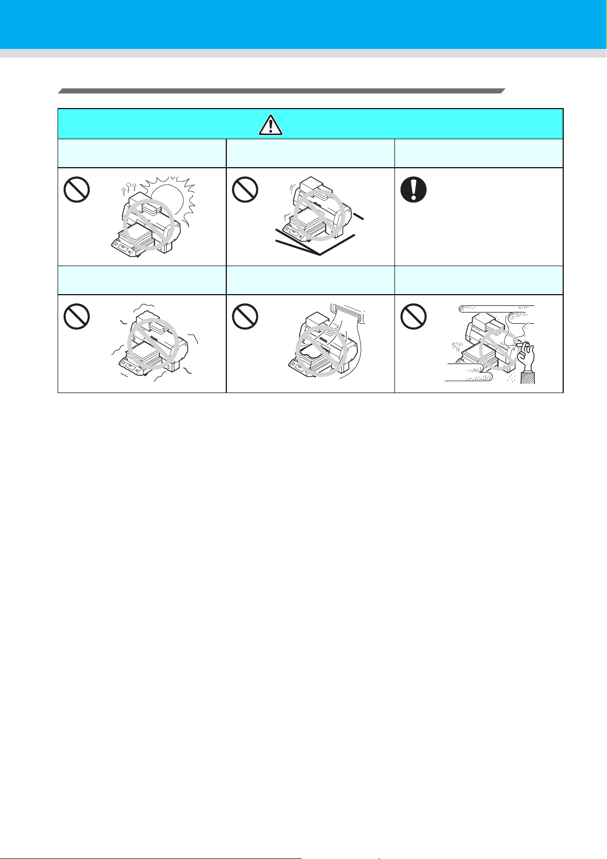
Precautions for installation
CAUTION
A place exposed to direct
sunlight
A place that vibrates
A place that is not horizontal
A place exposed to direct air
blow from air conditioner, etc.
A place where temperature and
humidity varies significantly
•Use the machine under the
following environment.
Operating environment :
20 ~ 35 ℃ (68 to 95 F)
35 ~ 65% (Rh)
Around a place where fire is
used
xiv
Page 15
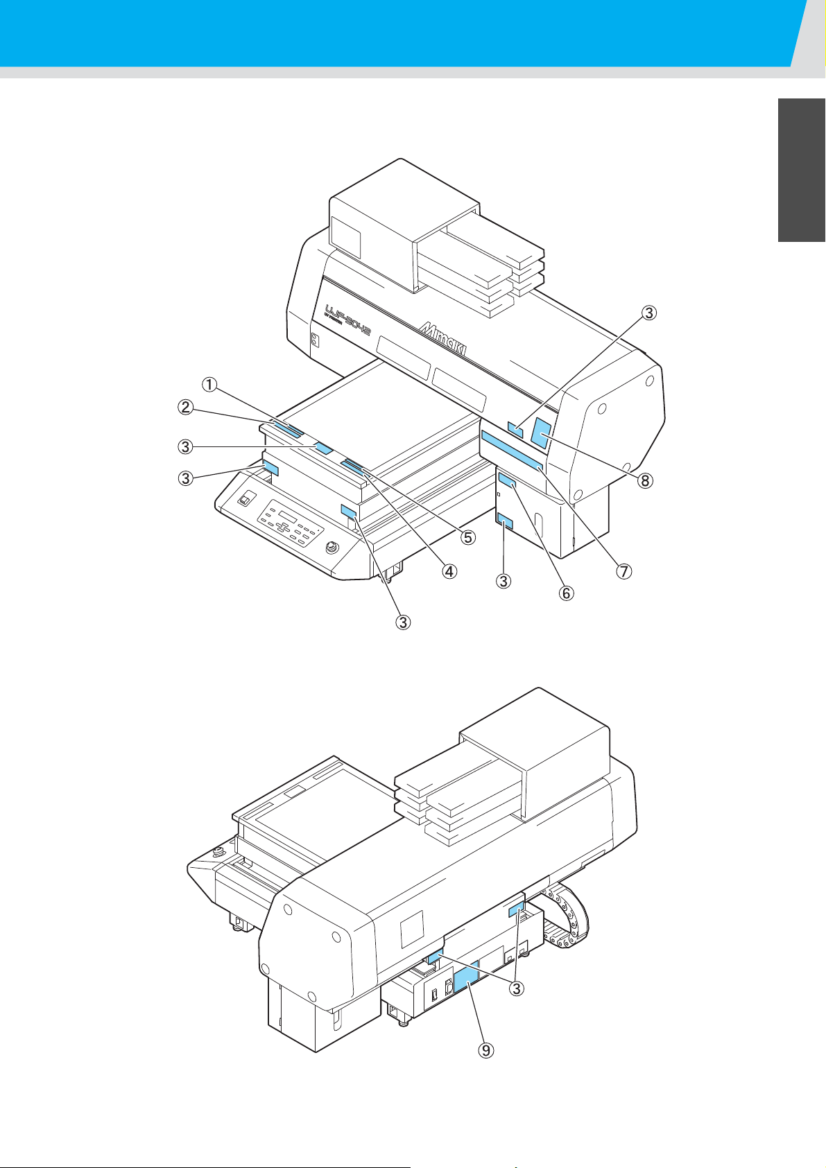
Position of the warning label
Warning labels are adhered on this machine. Be sure to fully understand the warnings given on the labels.
In the case where any of the warning label has become so soiled that the warning message is illegible or has
come off, purchase a new one from your local distributor or our office.
Position of the warning label
xv
Page 16
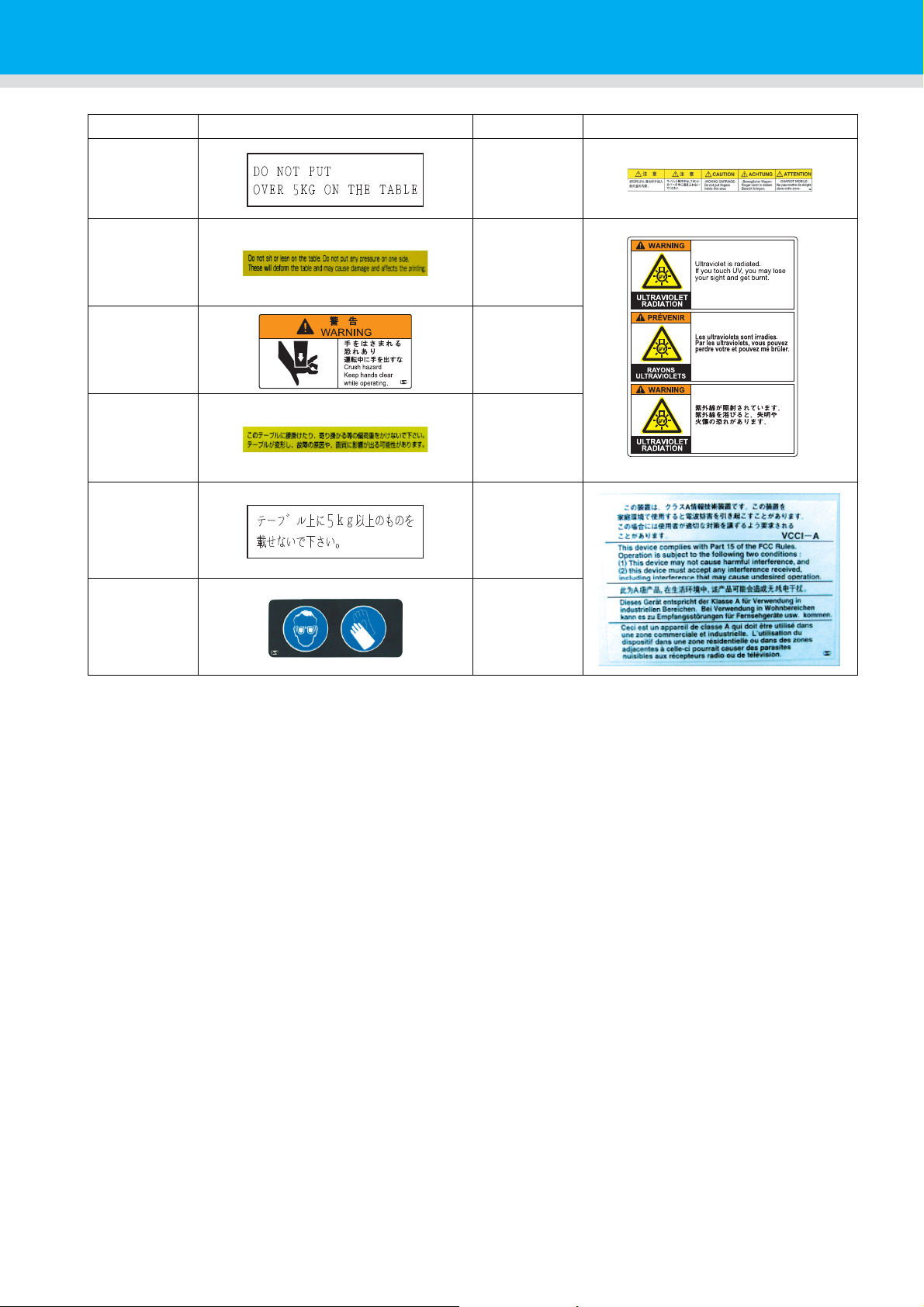
Order No. Label Order No. Label
(1) M907328 (7) M901549
(2) M904325 (8) M905980
(3) M904813
(4) M903226
(5) M907327 (9) M902535
(6) M903330
xvi
Page 17
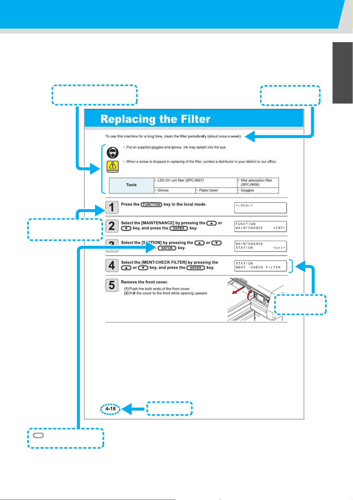
How to Read This Operation Manual
This explains the
outline of functions.
These are what we want you
to know in advance.
These are the number of
operation procedures.
This shows the
display panel.
Page number
enclose shows the
buttons in a sentence.
This manual provides the explanation about the displayed characters and used keys on the “Display Panel” in
addition to the operation procedures.
Proceed operations confirming them while using.
How to Read This Operation Manual
xvii
Page 18

xviii
Page 19

CHAPTER 1
Before Use
This chapter describes the parts name and setting procedures
before use.
Installing the machine......................................................... 1-2
Where to install the machine .......................................................1-2
Moving this machine ...................................................................1-3
Configuration and Function................................................ 1-4
Front ...........................................................................................1-4
Rear ............................................................................................1-4
Operation Panel ..........................................................................1-5
Carriage ......................................................................................1-6
EMERGENCY SWITCH ..............................................................1-6
Connecting the cables......................................................... 1-7
Connecting the USB2.0 interface cable ......................................1-7
Connecting the power cable .......................................................1-7
Setting of ink cartridge........................................................ 1-8
Kinds of ink that can be used ......................................................1-8
About Media ....................................................................... 1-10
The sizes of media that can be used ........................................1-10
Precautions in handling the media ............................................1-10
Menu mode......................................................................... 1-11
Page 20

Installing the machine
500 mm or more
(19.7 in or more)
1800 mm or more
(70.9 in or more)
2090 mm or more
(82.3 in or more)
500 mm or more
(19.7 in or more)
300 mm
or more
(11.8 in
or
more)
300 mm
or more
(11.8 in
or
more)
Where to install the machine
Secure sufficient space for installation before assembling this machine.
Decide the place considering the size of the machine and a space required for drawing.
Width Depth Height Total Weight
1200 mm (47.5 in) 1090 mm (42.9 in) 770mm (30.3 in) Approx.113 kg (249.1 lb)
1-2
Page 21

Installing the machine
Handles for transporting
Moving this machine
Move this machine as follows when this machine is required to move on the step-free same floor.
• When moving this machine, take care not to give a significant impact on
it.
• When moving this machine, keep it as flatly as possible. Do not move it
on its side. It may cause machine failure.
• Before moving this machine, install the handles for transporting. (two places)
Insert the handles into this machine, and fix them tightening screws.
1
Before Use
• For safety, be sure to work it with more than 4 people.
• Do not push the cover to move this machine since the cover may be deformed. Be sure to hold the handles for
transporting when moving the machine.
1-3
Page 22

Configuration and Function
Ink station
Insert ink cartridges here.( P.1-8)
Table ( P.2-4)
Set media on it.
There are absorbing holes on the
table so that media is absorbed
when vacuum is ON.
Operation Panel ( P .1-5)
Operation keys for setting the
machine, and a display to display
operation items are placed.
Power button
Turn ON/OFF the power of
this machine instead of the
power switch of main body.
( P.2-3, P.2-12)
Y-bar
Moves on the table at drawing.
Carriage ( P.1-6)
Unusable
(used for maintenance)
Main power switch
Turn ON/OFF the power of the
machine.
USB socket
Connect USB interface cable.
Front
Rear
1-4
Page 23
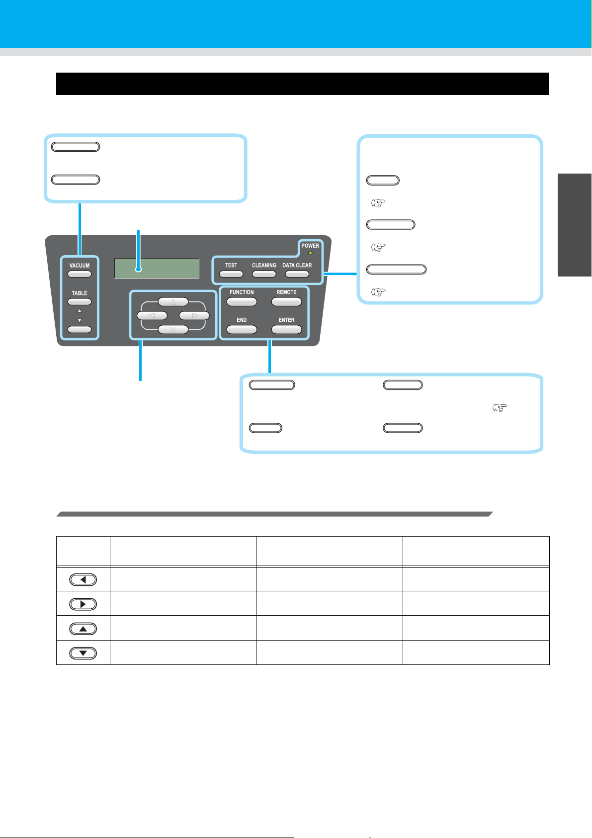
Operation Panel
Display
Displays state of the machine, setting items, errors, and so on.
Key
Press to switch ON/OFF of the vacuum.
VACUUM
POWER Lamp
Lights when the power is ON.
Key
Press to start the test drawing.
( P.2-6)
Key
Press to start the head cleaning.
( P.2-8)
CLEANING
Key
Press to erase received data.
( P.3-10)
DATACLEAR
JOG key
Used for moving of the Y-bar
and for each setting.
key
Press to use each function.
key
Press to switch the remote mode and the
local mode, and vice versa. ( P.1-1 1)
key
Press to finish the setting.
END
key
Press to determine a setting.
Key
Press to raise or lower the table.
TABLE
The operation panel is used for setting of drawing method and each operation.
TEST
Configuration and Function
1
Before Use
Function of Jog Keys
A function of the Jog key is different by the timing to be used.
At drawing origin, area setting At function selection At setting selection
Shifts the carriage to the left
Shifts the carriage to the right
Shifts the carriage to the back Return to the previous function Select the previous function
Shifts the carriage to the front Mo v e to the next function Select the next value
FUNCTION
REMOTE
ENTER
1-5
Page 24
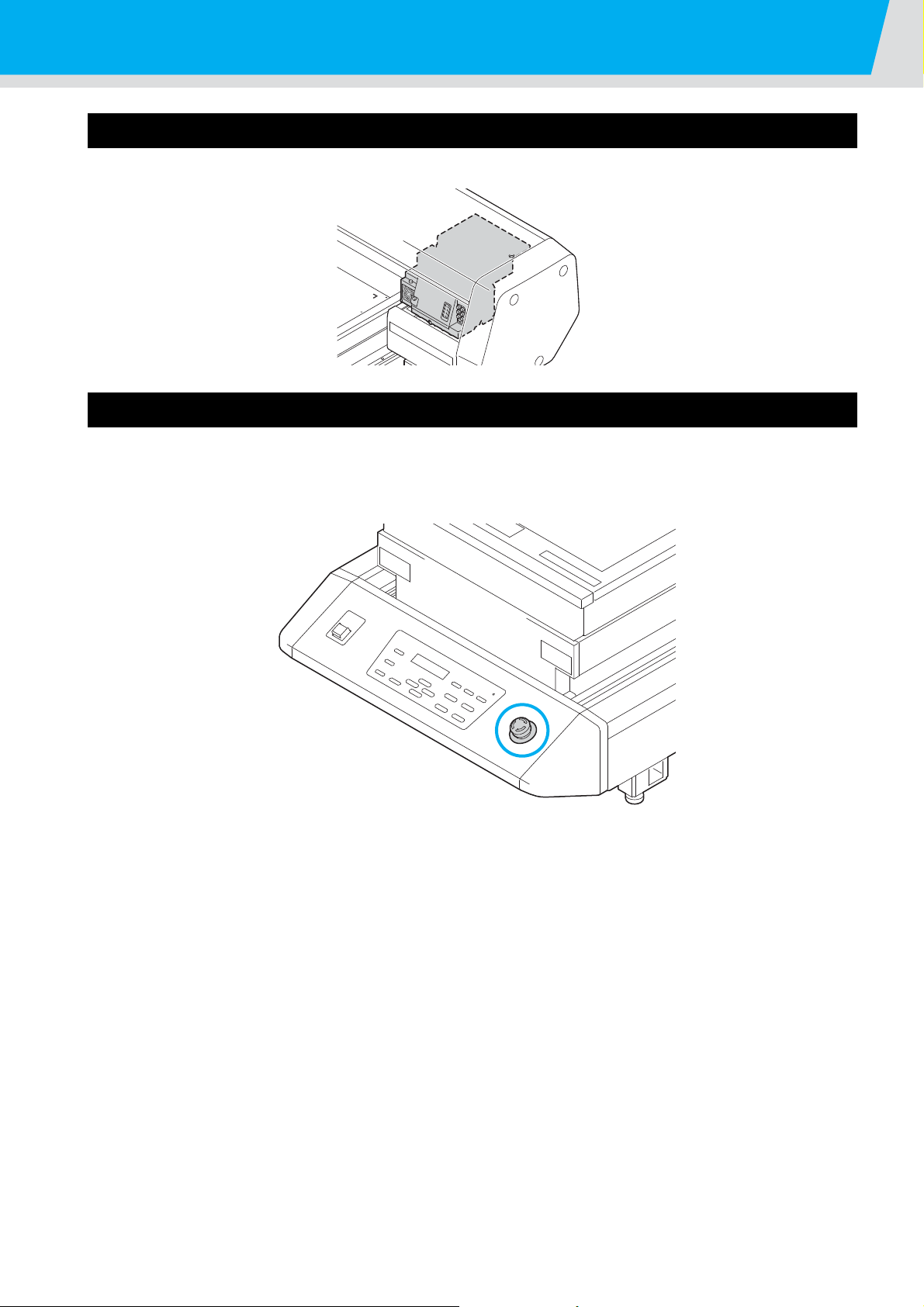
Configuration and Function
Carriage
A print head for drawing, LED UV device, and a light pointer in the print head cover are mounted on the carriage.
EMERGENCY SWITCH
When stopping the machine for safety reason, press the switch.
One EMERGENCY switch is placed on the front face of the machine.
1-6
Page 25

Connecting the cables
Connecting the USB2.0 interface cable
Connect a computer to this machine with the USB2.0 interface cable.
• Prepare the USB2.0 interface cable. (USB2.0 interface cable is not supplied with this machine.)
• Your RIP is required to support USB2.0 interface.
• If USB2.0 interface is not installed in your computer, ask a RIP maker near you or our branch office.
1
Before Use
Connecting the power cable
• Use only the supplied power cable.
• Be sure to connect the power cable plug to the grounded outlet, or it may cause fire or electric shock.
• T ake care not to damag e, break or work upon the power cable. Or if putting a heavy thing on, heating, or
pulling the power cable, the power cable can break to cause fire or electric shocks.
1-7
Page 26
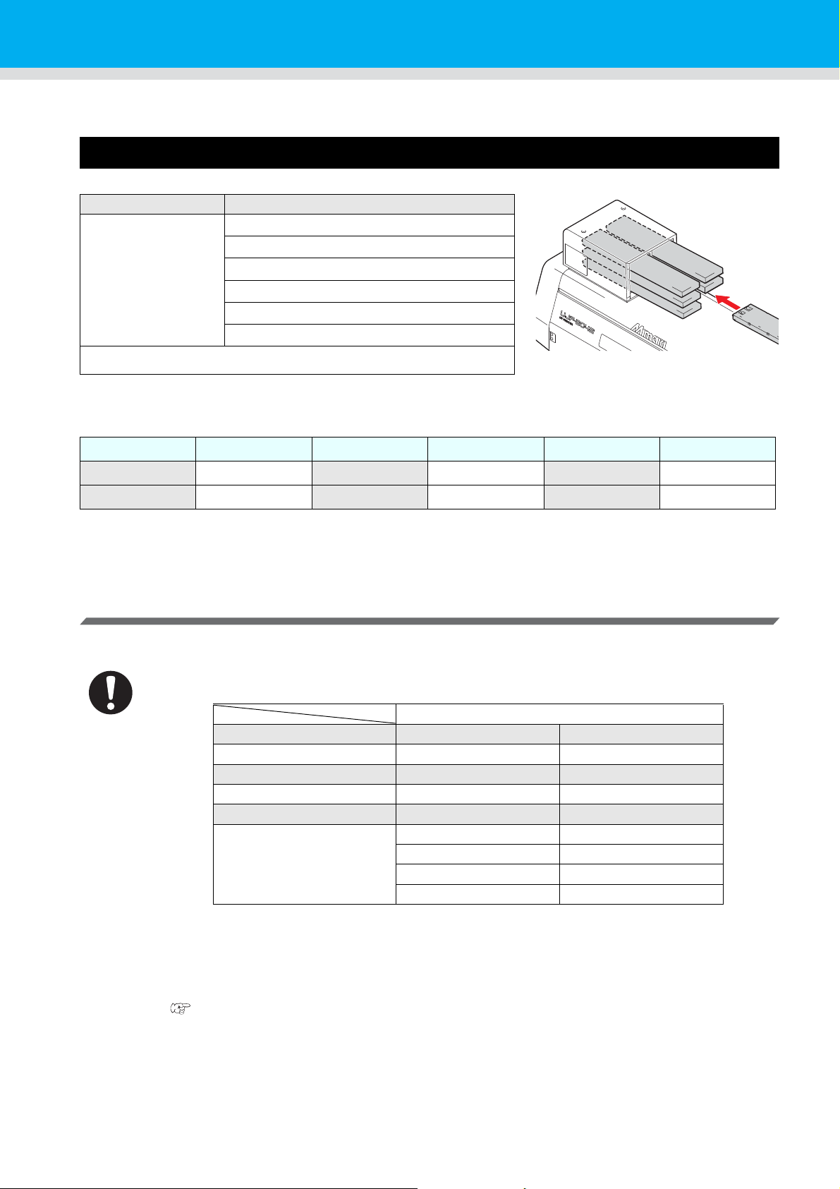
Setting of ink cartridge
UV Ink
Ink slot No. 1 2
Ink color
*1
*1. M=Magenta, C=Cyan, Y=Yellow, K=Black, W=White, CL=Clear
MC
Ink slot No. 3 4
Ink color Y K
Ink slot No. 5 6
Ink color
WW
CL CL
WCL
-- --
Use the ink cartridge inserting it into the ink station.
Kinds of ink that can be used
Ink Type Color
UV Ink
Cleaning cartridge
*1. To be used when the head is cleaned.
*1
Each color is displayed on the LCD as follows:
Display Color Display Color Display Color
M Magenta Y Yellow WWhite
C Cyan KBlackCL Clear
Magenta
Cyan
Yellow
Black
White
Clear
Precautions at the time of setting the ink cartridge
When setting the ink cartridge, pay attention to the followings:
• Confirm the ink slot number and insert the ink cartridge of the correct color.
• Insert the ink cartridge securely all the way in the slot. Moreover, do not insert or pull out the cartridge
roughly.
• Insert the cartridge making the IC chip side facing upward.
• For replacing the ink cartridge and the ink type, see the page below.
( P.4-4 "Ink cartridge")
• If the ink near end board comes out even when ink remains, shake the cartridge, check that the ink near
end board returns and then set it.
1-8
Page 27

Precautions in handling ink cartridge
• Use the recommended ink cartridge by Mimaki.
• Do not touch the ink directly. If the ink settles on the skin or clothes, immediately wash it off with soap
and water. If you get ink in your eyes, immediately wash your eyes with a lot of clean water. Then,
consult a doctor as soon as possible.
• Store ink cartridge in a dark and cold place.
• If the ink cartridge is moved from a cold place to a warm place, leave it in the room temperature for
more than three hours before using it.
• Be sure to thoroughly consume the ink in the ink cartridge, once it is opened, within six months. If an
extended period of time has passed after opening the cartridge, drawing quality would be poor.
• Store ink cartridges in a place that is out of the reach of children.
• When discarding unused ink cartridges, entrust them to an industrial waste disposal contractor,
clarifying their contents.
• Some component (photoinitiator) of the ink is toxic against aquatic organisms. Avoid leakage of it to
natural water system or domestic waste water.
• Do not use ink cartridges expired the date noted on them.
• Before using an ink cartridge, be sure to read the Safety Data Sheet (SDS).
• Do not shake the ink cartridge violently. Shaking or turning it toughly can cause leakage of ink.
• Never disassemble the ink cartridge.
• Never refill the ink cartridge with ink. Refilling the ink cartridge can cause a trouble. Remember that
Mimaki assumes no responsibility for any damage caused by the use of the ink cartridge replenished
with ink.
Setting of ink cartridge
1
Before Use
1-9
Page 28

About Media
The sizes of media that can be used and the method of handling are described here.
The sizes of media that can be used
Maximum width
Maximum length
Max. drawing width
Max. drawing length
Thickness
Weight
*1. A rough guide is 50 kg per 1 m2.
*1
Precautions in handling the media
Carefully observe the following when handling the media.
• Extension and shrinkage of the media
Do not use the media in the sheet form shortly after the package was opened. The media could extend
or shrink depending on the temperature and humidity inside the room. For more than 30 minutes after
opening of the package, the media has to be exposed to the ambient air of the location it is to be used.
• Warping of the media
As for the media of the sheet form, use the flat one, or the one warping downward (the one with floating
central part when placed the drawing surface facing upward.) The media warping upward could not be
absorbed in some cases onto the table. Store the media liable to be warped on the slightly smaller
platform or palette so that it may warp downward.
• Adsorption of the media
To maintain the adsorption effect, cover the suction holes not covered by the media with other media
which is thinner than the media.
• Other precautions
a Do not place any article on the surface of the coated paper. Some coated paper could change its
color.
b Curled media that cannot be absorbed or the media that misaligns when the Y-bar is moved may not
be used. Before using, fix the media with adhesive tape, etc.
c Do not use the media that will generate warping or deformation.
d The suction holes could affect the printed images depending on the thickness and elasticity of the
media. Perform printing after confirming that there is no problem by making the test printing in
advance.
300 mm
420 mm
300 mm
420 mm
Less than 50mm
Less than 5 kg
1-10
Page 29

Menu mode
TEST
CLEANING
FUNCTION
REMOTE
REMOTE
This machine has three modes. Each mode is describe d be low.
Local Mode
Local mode is a mode in drawing preparation state.
All keys are available.
Receiving of data from the computer is allowed, however, drawing is not executed.
The following operations are allowed in the local mode.
(1)Setting an origin and the table height by pressing the JOG keys.
(2)Executing “Test drawing” by pressing the key.
(3)Executing “head cleaning” by pressing the key.
(4)Execute setting of each function by pressing the key.
Function Mode
Press the key during the Local Mode to call the Function Mode.
Function settings on drawing method can be set.
FUNCTION
1
Before Use
Remote Mode
Remote mode is a mode in drawing received data.
Pressing of the key suspends the machine.
Press the during the Local Mode to switch to the Remote Mode.
1-11
Page 30

1-12
Page 31

CHAPTER 2
Basic Operations
The procedure from preparation of ink and media to the execution
of drawing, and setting methods are explained.
Operation flow...................................................................... 2-2
Turning the power ON......................................................... 2-3
Setting the media................................................................. 2-4
Set the media in another method ................................................2-5
Test drawing......................................................................... 2-6
Execution of head cleaning ................................................ 2-8
Drawing an image from source data.................................. 2-9
Starting the drawing operation ....................................................2-9
Interruption of drawing ..............................................................2-10
Checking drawing data that is being received or
has been received ....................................................................2-10
When [! WORK High] is displayed ............................................2-11
If you open the cover during drawing ........................................2-11
Turning the power OFF ..................................................... 2-12
Page 32
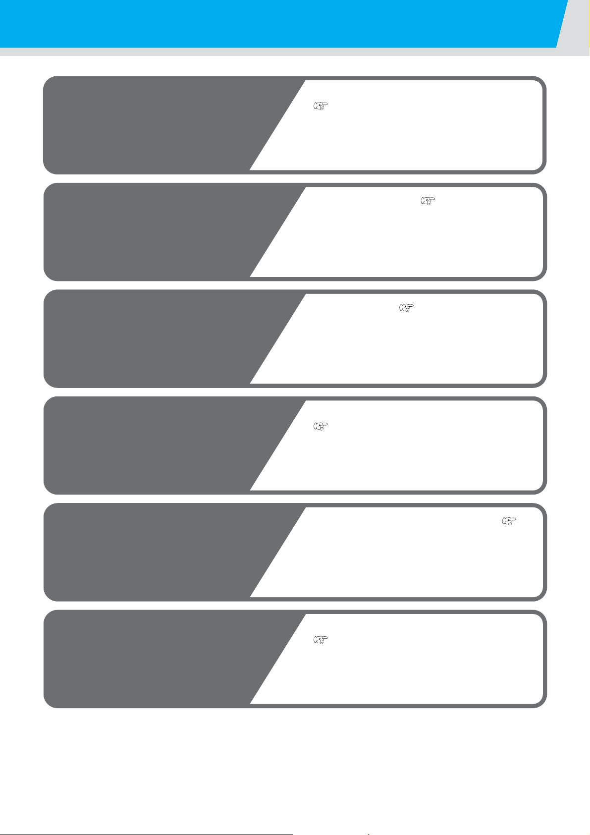
Operation flow
1
Turning the power ON
2
Setting the media
3
Test drawing
4
Execution of head cleaning
5
Drawing an image from source
data
6
Turning the power OFF
See "Turning the power ON"
(P.2-3)
See "Setting the media" ( P.2-4)
See "Test drawing" ( P.2-6)
See "Execution of head cleaning"
(P.2-8)
See "Drawing an image from source data" ( P.2-
9)
See "Turning the power OFF"
( P.2-12)
2-2
Page 33
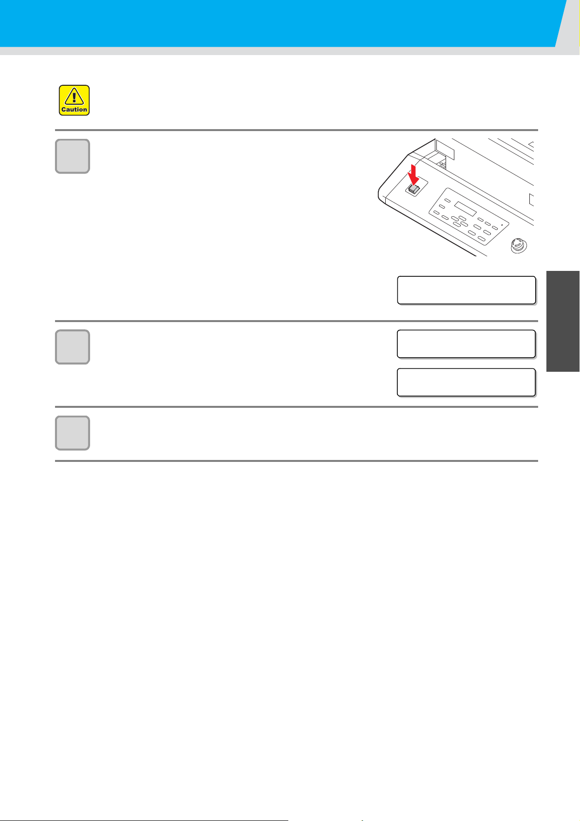
Turning the power ON
UJF-3042FX st ar t-up
ver . * . **
<LOCAL>
PLEASE WAI T
SEARCHI NG ORIG IN
• When the power is turned ON, the Y-bar moves. To avoid injuries, keep your hands away from the table.
Press the power button.
1
• Press the power button on the left side of the operation panel
to light.
• When the main power switch is not set to ON, the power is not
connected even if the power button is pressed. If the lamp
does not light even if the button is pressed, check the main
power switch on the rear of this machine.
• When the power is switched on, the LCD displays the
firmware version.
2
2
3
Initial operation is started.
• Local Mode starts.
Turn the power of connected computer ON.
Basic Operations
2-3
Page 34

Setting the media
ENTER
Adsorption
area
VACUUM
ENTER
• To avoid lifting of media, turn ON the adsorption fan after setting media.
• If, within the adsorption area, there are suction holes not closed by the media, close such suction holes
placing thin sheet form material such as paper, film or tape.
• The peripheral parts of the media could roll up due to heat. Fix the media supplementarily using
adhesive tapes, etc.
Open the table front cover.
1
Set media along the L-shaped mark (drawing
2
origin) on the right corner of the table.
• To change the drawing origin, see the following page.
( P.3-2 "Changing origin")
• T o use tools, set into the shaves (8.0 mm-deep) on the corners
of the table.
3
4
5
Close the table front cover, and press the key.
• The origin is detected. Please wait until the operation is finished.
Press the key depending on the
intended use.
• The media is fixed.
To avoid media lifting, be sure to turn ON the vacuum fan if
using thin media.
Adjust the table to an appropriate height for drawing by pressing the
TABLE keys, and press the key.
• Adjust the height of the table with the media to 50 mm or less.
2-4
Page 35
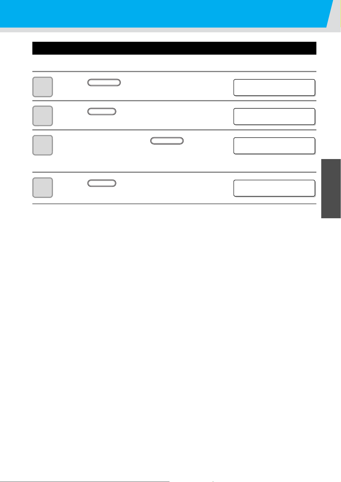
Set the media in another method
<LOCAL>
FUNCTION
FUNC T I ON
WO R K SE T < E N T >
WO R K SE T
COMPL E TE D : e n t
FUNCTION
WO R K SE T
COMPL E TE D : e n t
You can move the Y bar to the rear so that you may set the media easier.
Press the key in the local mode.
1
Setting the media
2
3
4
Press the key.
• The table is lowered.
To check the height, press the key.
• The table height can be checked after the table lifts to the
specified height, the obstacle sensor works, and the Y-bar
moves to the front.
Press the key.
• The table is lifted to the specified height.
ENTER
ENTER
2
Basic Operations
2-5
Page 36

Test drawing
<LOCAL>
TEST DRAW
(SCAN DIR) <ENT>
TEST DRAW
(FEED DIR) <ENT>
ENTER
When FEED DIR is selected
When SCAN DIR is selected
TEST DRAW
NOZ Z L E R ECOV ERY : ON
Make test drawing in the specified directio n to check whether there is nozzle clogging or other drawing failures
(such as wearing or missing).
• When you use white ink and clear ink, print on the clear film to check.
Check before starting
test drawing
Press the key in the local mode.
1
Select the drawing direction by pressing the
2
or key, and press the key.
• When nozzle recovery is not set, test drawing is started in the
selected direction.
• SCAN DIR: Draws in the scan (widthwise) direction of the media.
• FEED DIR: Draws in the feed (longwise) direction of the media.
• Is media set? ( P.2-4) • Is origin point set? ( P.3-2)
TEST
When nozzle recovery is set, press the or key
3
4
5
to set ON/ OFF and then press the key.
• This is available for F/W Ver.3.30 and later.
• ON: Draws with nozzle recovery ON.
OFF: Draws with nozzle recover OFF.
Test drawing ends.
• Y-bar evacuates from the table, and then the mode returns to the local.
Check result of drawing.
• When the result is normal, finish the operation. ( P.2-9)
• When the result is abnormal, execute head cleaning. ( P.2-8)
ENTER
2-6
Page 37
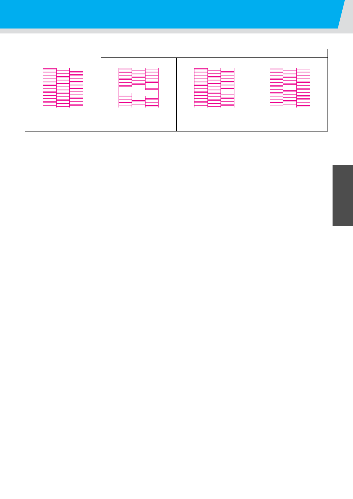
Test drawing
Many lines are missing.
The lines are missing as if the
teeth are lost.
The distance between the
lines is narrowing or double
lines are formed.
Normal pattern
Abnormal patterns
Nozzle drop out Nozzle missing Deflection
2
Basic Operations
2-7
Page 38
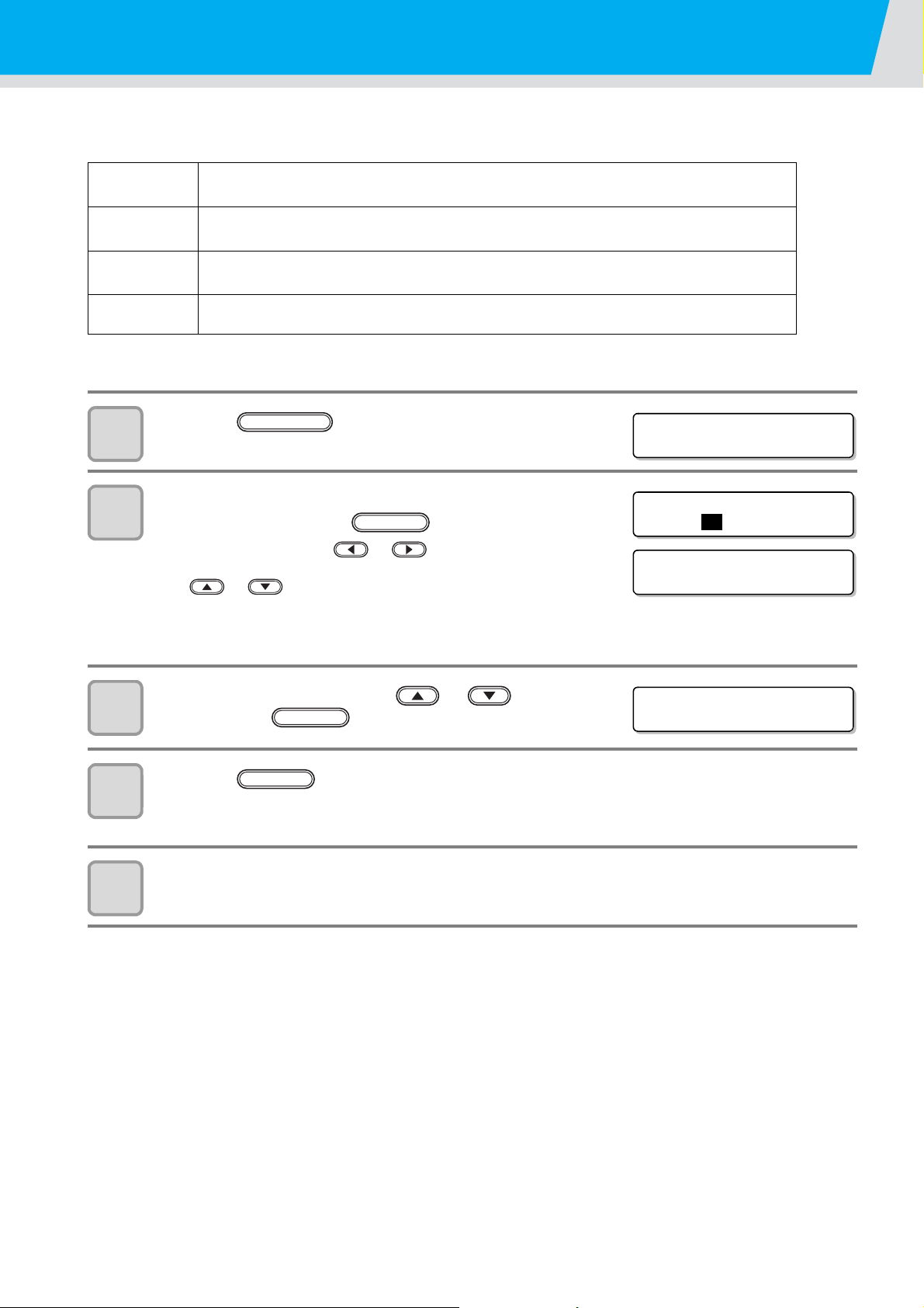
Execution of head cleaning
<LOCAL>
CLEANING
#CLEANING
HEAD [
MC
YKW
C
L
]
#CLEANING
HEAD [ _ _YKW
C
L
]
#CLEANING
TYPE : no rmal
When a correct pattern is not obtained in the test drawing, perform the head-cleaning. As for the head cleaning,
the following 4 types are available.
normal
hard To be used when the missing of the lines does not improve with the “normal” cleaning.
soft To be used when the lines are curved.
Flushing
*1. Supported from the firmware ver.3.80.
Press the key in the local mode.
To be used if ten odd numbers of the lines are missing when the test pattern is made.
Suction and wiping will be performed.
*1
To be used when mixed colors (for example, black mixed in yellow) occur.
1
Select the head, set execution/non-execution of
2
cleaning, and press the key.
(1)Select the head with or keys.
(2)Select execution/non-execution of the head cleaning wi th
or keys.
Select execution of cleaning for every head.
Execute Cleaning:Head No. being set is displayed.
Not Execute Cleaning:“ - ” is displayed.
ENTER
3
4
5
Select the cleaning type with or keys,
and press the key.
Press the key.
• Cleaning is started.
• When the cleaning is completed, a mode is returned to the local mode.
Execute test drawing and check the result of the test drawing.
• Repeat cleaning and test drawing until normal result is obtained.
ENTER
ENTER
2-8
Page 39
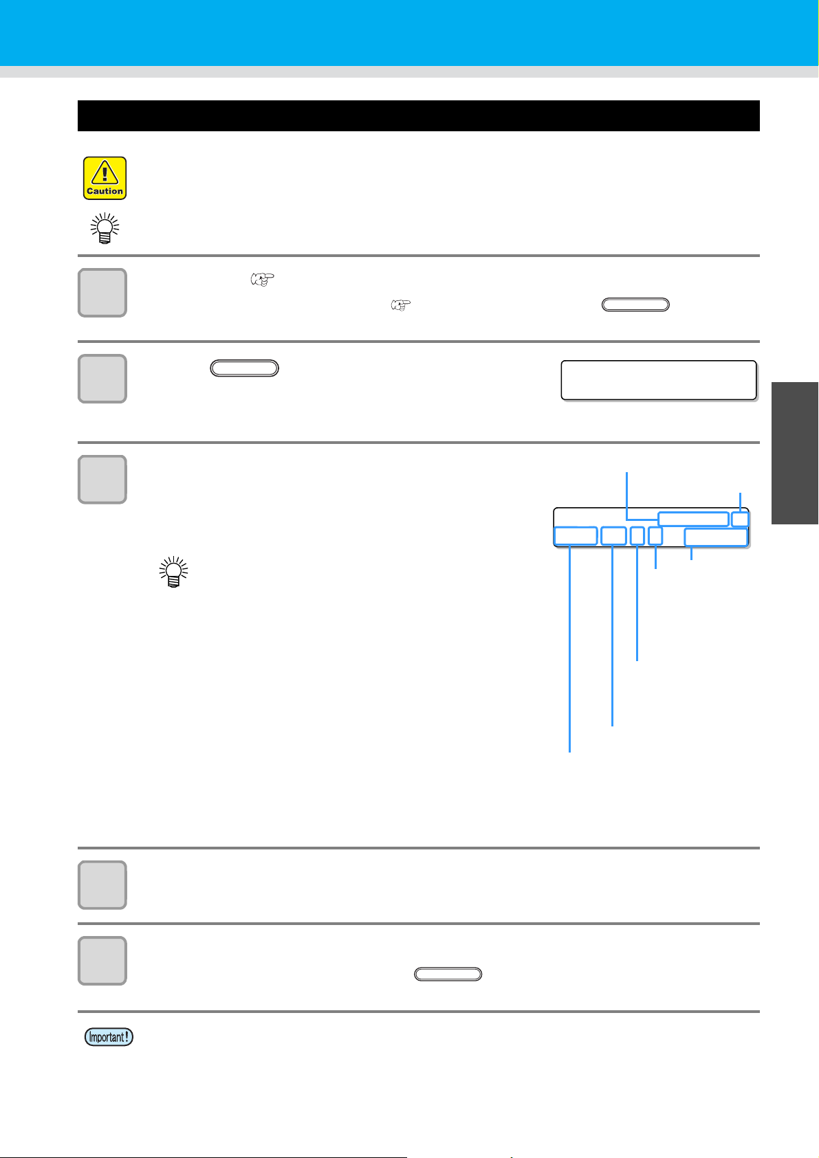
Drawing an image from source data
VACUUM
*REMOTE*
49.0mm
*REMOTE* 720X600 R
HOST/16/U/N 49.0mm
Pass
Priority is set to “HOST” :
“HOST” is displayed.
Priority is set to “PLOT” :
Print quality (STD/FINE/FAST) is
displayed.
Direction:
“B” denotes bi-directional.
“U” denotes uni-directional.
Scanning speed:
“N” denotes normal.
“H” denotes the
double speed.
Table height
Resolution
With/ without nozzle
recovery setting
VACUUM
Starting the drawing operation
• If the temperature of the head has not reached the predetermined value, a message is displayed.
Drawing is not allowed in such cases. When the display is disappeared, drawing can be started.
• Data transmission is allowed even if errors are displayed. Drawing is started after the display is
disappeared.
Set the media. ( P.2-4)
1
(1)When you set the vacuum fan setting ( P.3-19) to “MANUAL”, press the key depending
on the use and vacuum the media.
2
3
Press the key in the local mode.
• The machine goes in the remote mode and data from the
computer can be received.
• The table height is displayed.
Transmit data to be drawn from the computer.
• Drawing conditions are displayed.
• As for the data transmission method, see the instruction manual
of the output software.
REMOTE
• This machine does not have “H” (double speed)
and “B” (bi-directional).
2
Basic Operations
4
5
Start drawing.
• The drawing origin is not changed after completion of the drawing.
Taking out the media after completion of drawing.
(1)When you made vacuum ON, Press the key to turn the adsorption OFF.
(2)Remove the media.
• During printing, media may be heated by the LED UV and raised, causing drawing to be interrupted. In
this case, set new media and restart drawing.
2-9
Page 40

Interruption of drawing
<LOCAL>
REMOTE
DATA CLEAR
<ENT>
** DATA CLEAR **
<LOCAL> DT
DAT A REMAI N
REMOTE
<LOCAL> DT
INK NEAR END___K___W
To interrupt drawing, stop the drawing operation and erase the received data from the machine.
1
Press the key while drawing.
• Drawing operation stops.
• When data is transmitted from the computer, the computer
stops transmission of data.
• To restart drawing, press the key again.
Press the key.
REMOTE
DATACLEAR
2
Press the key.
3
• Received data is erased and the machine returns to the local
mode. Y-bar moves to the evacuation position.
Checking drawing data that is being received or has been received
ENTER
The next displayed if you cancel drawing or if you received the drawing data on
the Local.
At this time, if you press the key to migrate to the remote, drawing is
started or restarted.
• Even if a separate warning or error is displayed in the second
(Supported from the firmware ver.4.10)
line of the display, if DT is displayed on the upper-right hand
side, it means the device has undrawn data.
2-10
Page 41
Drawing an image from source data
ERROR 5 0 5
!WORK High
<LOCAL>
REMOTE
DATACLEAR
Reset a swi tch
PR I NT I NG PAUSE
CONT I NUE < >CANCEL
ENTER
Resume P r i n t
PRESS <ENT > KEY
ENTER
( RESET SWI TCH )
PRESS <ENT> KEY
ENTER
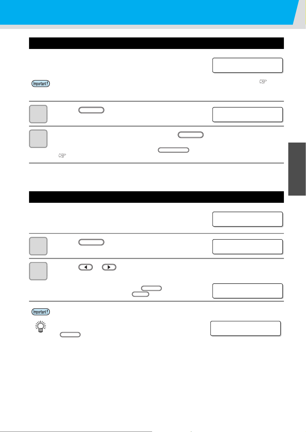
When [! WORK High] is displayed
When [! WORK High] is displayed on the screen and the drawing operation
stops during drawing, restart drawing with the procedures below:
• During drawing, the sensor always monitors the media height. When the gap check function ( P.3-7)
is set to “OFF”, if the sensor detects the media, the drawing operation is interrupted automatically, and [!
WORK High] is displayed on the screen.
1
2
Press the key.
• The screen returns to LOCAL.
Check the media setting status, and press the key.
• The machine restarts drawing.
• If you do not wish to restart drawing, press the key to interrupt drawing.
( P.2-10 “Interruption of drawing”)
ENTER
If you open the cover during drawing
If you open the cover or press the emergency stop switch during drawing, the
warning message is displayed on the screen.
Press the key.
1
2
Basic Operations
2
Press the or key to select “CONTINUE” or “CANCEL” of drawing.
• When you select “CANCEL”, the machine starts initialization.
• When you select “CONTINUE”, the right screen is displayed.
When you continue drawing, press the key.
When you stop drawing, press the key.
• When you continue drawing, image missing may occur depending on the timing of the cover opened.
• When you open the cover when the drawing operation is not
performed, the right screen is displayed. In this case, press the
key
END
2-11
Page 42
Turning the power OFF
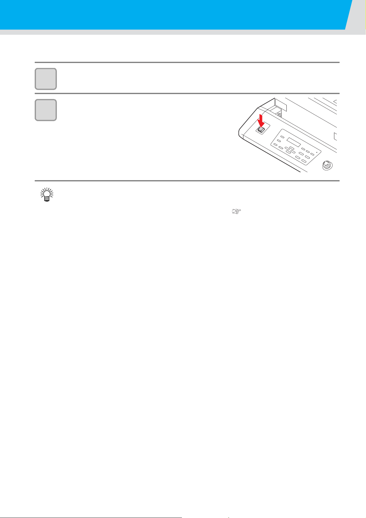
To turn off, check first whether or not there is data received and there remains da ta that has not ye t been outp ut
in the machine.
Turn the power of the connected computer off.
1
Press the power button to cut the power.
2
When this machine is not used for a long time, execute the following:
(1) Press the power button.
(2) Confirm that the shutdown operation is completed.
(3) Turn off the main power switch on the rear of this machine. ( P.1-4)
2-12
Page 43

CHAPTER 3
Useful Function
Items required for using this machine conveniently, such as an
ink replacing method or a cleaning manner, are described.
Changing origin.................................... 3-2
Changing origin with JOG keys ................3-2
Changing origin with FUNCTION menu ...3-3
Setting the Head Height....................... 3-4
Setting the media thickness .....................3-4
Setting the head gap ................................3-5
Setting the table height .............................3-6
Gap check ................................................3-7
Perform setting to reduce stripes be-
tween passes........................................ 3-8
Other useful functions....................... 3-10
Data clear ...............................................3-10
Displaying information of this machine ...3-10
Proceed with drawing that you suspended .311
Alternative nozzles for printing, when nozzles missing can not be improved
Checking ink landing displacement ........3-14
.............................3-12
Various settings.................................. 3-15
Setting the print method .........................3-15
Setting the mode of the LED UV ............3-16
Increasing cumulative UV irradiation
when the number of passes is low .........3-17
Setting of priority .....................................3-18
Setting the mode of the fan mode ..........3-19
Setting the work change .........................3-20
Setting the ink weight .............................3-21
Changing language display on the screen
Output the setting list ..............................3-23
Displaying machine information ..............3-24
Other useful settings ...............................3-26
Initializing settings ..................................3-27
Setting time .............................................3-28
Setting mm/ inch .....................................3-29
Setting weight of the empty cartridge .....3-30
Setting Key buzzer .................................3-31
Setting radiator pump .............................3-32
Setting the flushing level before printing .3-33
.3-22
Page 44

Changing origin
Changing with the JOG keys Changing with the “ORIGIN”
in the FUNCTION menu
OR I G I N S ET U P
0.0
---
OR I G I N S ET U P
420.0 300.0
Origin position
(back and forth)
Origin position
(right and left)
** ORIGIN **
The default origin position can be changed.
There are following 2 changing methods.
Changing origin with JOG keys
1
2
3
Press the keys
in the local mode.
• The origin setting mode starts
• A red light pointer mark [ ] is projected on the table or the media.
Move the light pointer mark by pressing the
keys.
• Move the light pointer mark to the position to set a new origin.
Press the key when the drawing origin is
determined.
• The origin is changed.
• The height of the table is also fixed at the same time. Adjust the height of the table by pressing the
TABLE keys in advance.
• The setting value for the origin set with the JOG keys is cleared by cutting the power.
• The setting of the table height holds even if turning off the power.
ENTER
3-2
Page 45

Changing origin
<LOCAL>
FUNCTION
FUNC T I ON
SET ORI GIN <ENT>
ENTER
OR I G I N 4 1 0mm
XOFFS: 10mm
OR I G I N
SELECT :Y OFFS
OR I G I N 2 9 0mm
YOFFS: 10mm
ENTER
Changing origin with FUNCTION menu
To precisely set the origin of coordinates, set its X- and Y- coordinates from the FUNCTION me nu. This setting
value becomes the origin position (0, 0).
Press the key in the local mode.
1
Select the [ORIGIN] by pressing the or
2
3
key, and press the key twice.
• X-axis offset value setting screen is displayed.
Input value by pressing the
or keys, and press the key.
• Setting the origin position of X-axis.
• The value in the parentheses indicates the distance from the origin to the maximum effective area.
ENTER
4
5
6
Select the [Y OFFS] by pressing the or
keys, and press the key.
Input value by pressing the or keys, and
press the key.
• Setting the origin position of Y-axis.
• The value on the first line indicates the distance from the origin to the maximum effective range.
Press the key several times to end the setting.
• The set value remains even if turning off the power.
END
ENTER
3
Useful Function
3-3
Page 46
Setting the Head Height
<LOCAL>
FUNCTION
FUNC T I ON
WO R K SE T < E N T >
ENTER
HEAD HE I GHT
MEDIA THICKNESS<ent>
HEAD HE I GHT
THI CKNESS : 1 . 0mm
ENTER
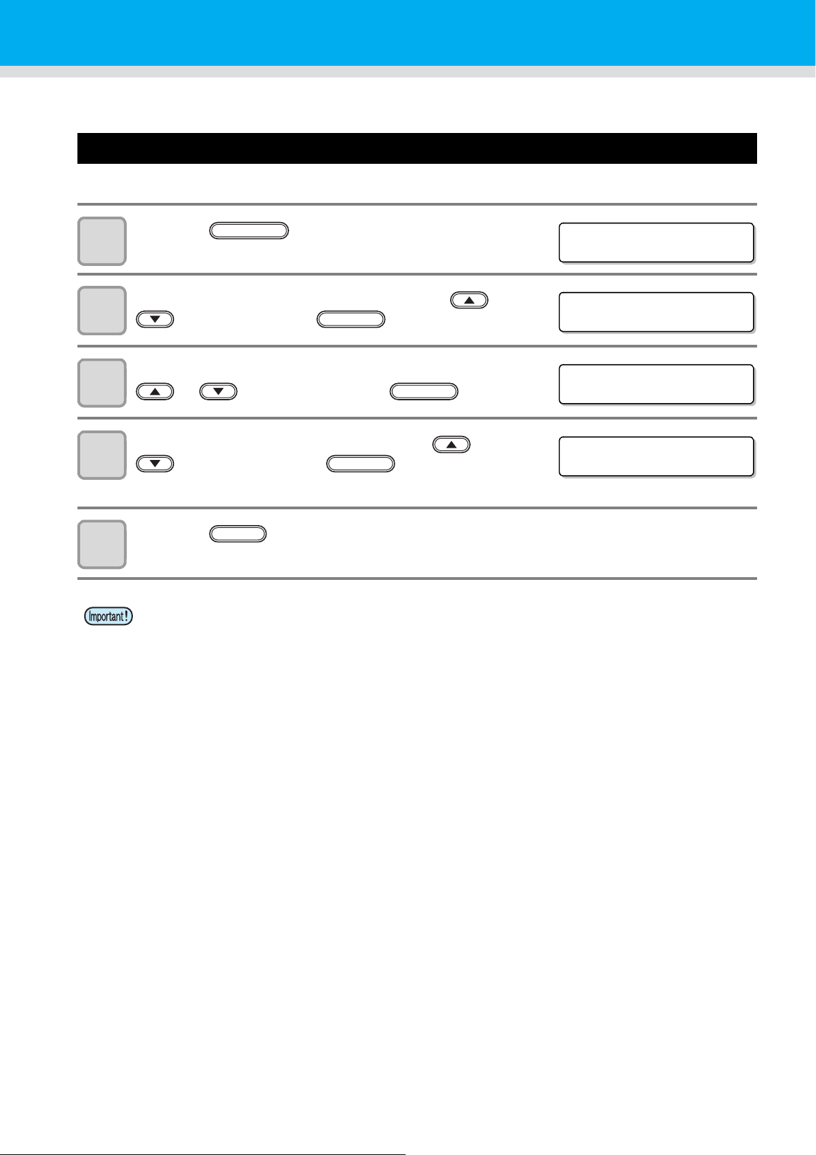
Media thickness, Head gap, and Table height can be changed.
Setting the media thickness
If the media thickness is changed, Table Height is also changed.
Press the key in the local mode.
1
Select the [HEAD HEIGHT] by pressing the or
2
3
4
key, and press the key.
Select the [MEDIA THICKNESS] by pressing the
or keys, and press the key.
Set the media thickness by pressing the or
keys, and press the key.
• Set value: 0.0mm to 50.0mm
ENTER
5
Press the key several times to end the setting.
• Adjust [MEDIA THICKNESS] or [TABLE HEIGHT] based on the head gap value so that [HEAD GAP] +
[MEDIA THICKNESS] + [TABLE HEIGHT] = 51.5mm.
If adjustment cannot be performed, an operation error is displayed.
END
3-4
Page 47
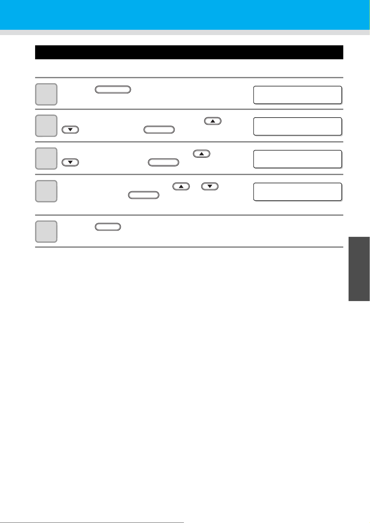
Setting the head gap
<LOCAL>
FUNCTION
FUNC T I ON
WO R K SE T < E N T >
HEAD HE I GHT
MEDIA THICKNESS<ent>
ENTER
HEAD HE I GHT
HEAD GAP : 1 . 5mm
If the head gap is changed, Table Height is also changed.
Press the key in the local mode.
1
Select the [HEAD HEIGHT] by pressing the or
2
3
4
key, and press the key.
Select the [HEAD GAP] by pressing the or
keys, and press the key.
Set the head gap by pressing the or
keys, and press the key.
• Set value: 1.5mm to 5.0mm
ENTER
ENTER
Setting the Head Height
5
Press the key several times to end the setting.
END
3
Useful Function
3-5
Page 48
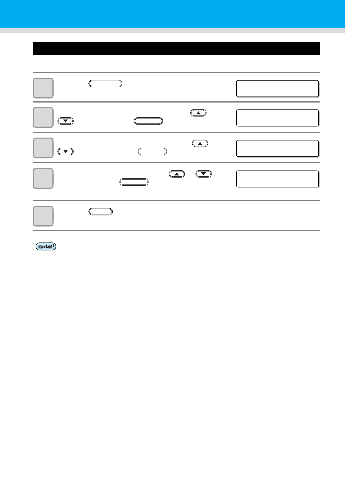
Setting the table height
<LOCAL>
FUNCTION
FUNC T I ON
WO R K SE T < E N T >
HEAD HE I GHT
MEDIA THICKNESS<ent>
ENTER
HEAD HE I GHT
TBL HEIGHT : 49 .0mm
If the table height is changed, Media Thickness is also changed.
Press the key in the local mode.
1
Select the [HEAD HEIGHT] by pressing the or
2
3
4
key, and press the key.
Select the [T ABLE HEIGHT] by pressing the or
keys, and press the key.
Set the table height by pressing the or
keys, and press the key.
• Set value: 0.0mm to 50.0mm
ENTER
ENTER
5
Press the key several times to end the setting.
• Adjust [MEDIA THICKNESS] or [TABLE HEIGHT] based on the head gap value so that [HEAD GAP] +
[MEDIA THICKNESS] + [TABLE HEIGHT] = 51.5mm.
If adjustment cannot be performed, an operation error is displayed.
END
3-6
Page 49
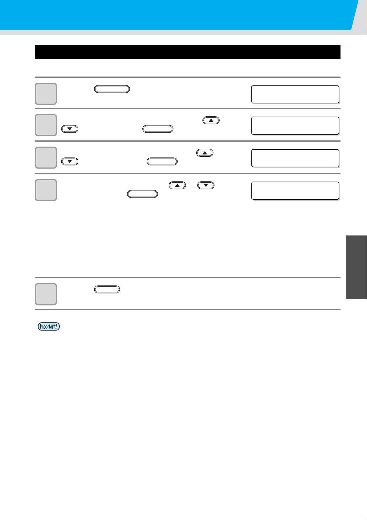
Gap check
<LOCAL>
FUNCTION
FUNC T I ON
WO R K SE T < E N T >
HEAD HE I GHT
MEDIA THICKNESS<ent>
ENTER
HEAD HE I GHT
GAP CHECK : ON
Select operation when obstacles are detected during drawing.
Press the key in the local mode.
1
Select the [HEAD HEIGHT] by pressing the or
2
3
4
key, and press the key.
Select the [GAP CHECK] by pressing the or
keys, and press the key.
Select the mode by pressing the or
keys, and press the key.
• Set value: ON, OFF
• When ON is selected:
Before drawing, the work height is checked with the specified table height (media thickness).
Before and during drawing, if the work sensor is shielded, the table is lowered until it is unshielded to
change the table height.
If the work sensor is shielded when the table is lowered to the bottom (table height 0.0mm), a message of
[WORK High] appears and the operation stops.
• When OFF is selected:
Before drawing, the work height is checked with the specified table height (media thickness), and if the
work sensor is shielded, a message of [WORK High] appears and the operation stops.
ENTER
ENTER
Setting the Head Height
3
5
Press the key several times to end the setting.
• The gap check function is not a function to avoid the head hit completely by detecting obstacles. Even
when the GAP CHECK is “ON”, be sure to check the work height visually before drawing.
END
Useful Function
3-7
Page 50
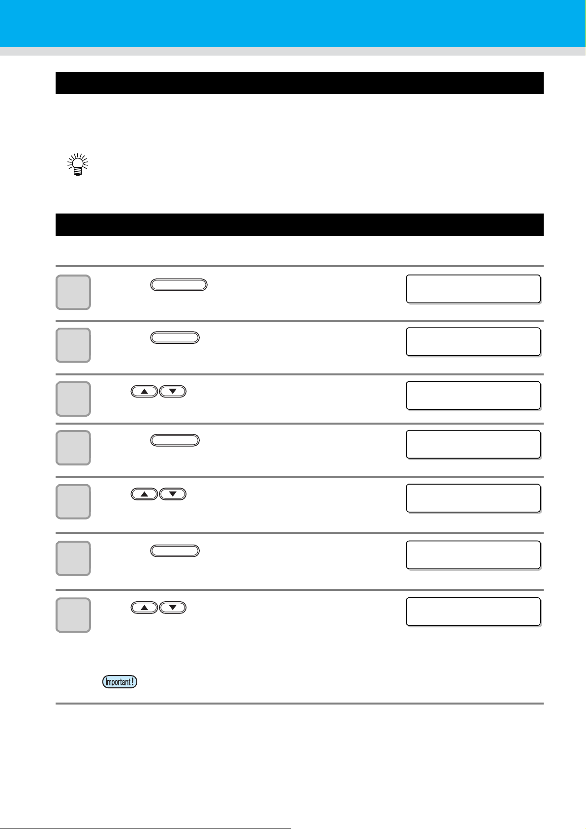
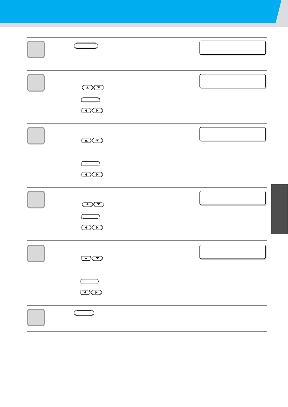
Perform setting to reduce stripes between passes
FUNCTI ON
SETUP < ENT>
FUNCTION
SETUP
FEED COMP . < ENT>
SETUP
MAPS <ENT>
MAPS
MAPS : OF F
MAPS
MAPS :MAPS2
MAPS 2
MAPS 2 : MANUA L
MAPS 2
MAPS 2 : AUTO
What is the MAPS Function?
If performing media correction does not resolve feeding stripes, use the MAPS (Mimaki Advanced PassSystem)
function to disperse the pass boundary to make the feeding stripes less visible.
With the UJF-3042, you can use the MAPS2 function
• Enabling the MAPS function, slight color change may be found compared to when the MAPS function
disable. Use it after checking effect in advance.
• MAPS may not be effective depending on image to be printed. Use it after checking effect in advance.
*1
. (Supported from the firmware ver.4.10)
Setting MAPS2 Function
Press the key in LOCAL.
1
2
3
4
5
6
7
Press the key.
Press to select [MAPS].
Press the key.
Press to select MAPS2.
•Set Value:MAPS2, OFF
Press the key.
• If you selected OFF in step 5, back to step 3.
Press to select “AUTO” or “MANUAL”.
• AUTO : Set the print pattern and smoothing level to the
• MANUAL : You can adjust the set value.
ENTER
ENTER
ENTER
recommended value automatically depending on
printing mode.
*1.This helps reduce feeding stripes and uneven color.
3-8
• If feeding stripes and color change is not improved by “AUTO” setting, please adjust the
print pattern and smoothing level by “MANUAL” setting.
Page 51
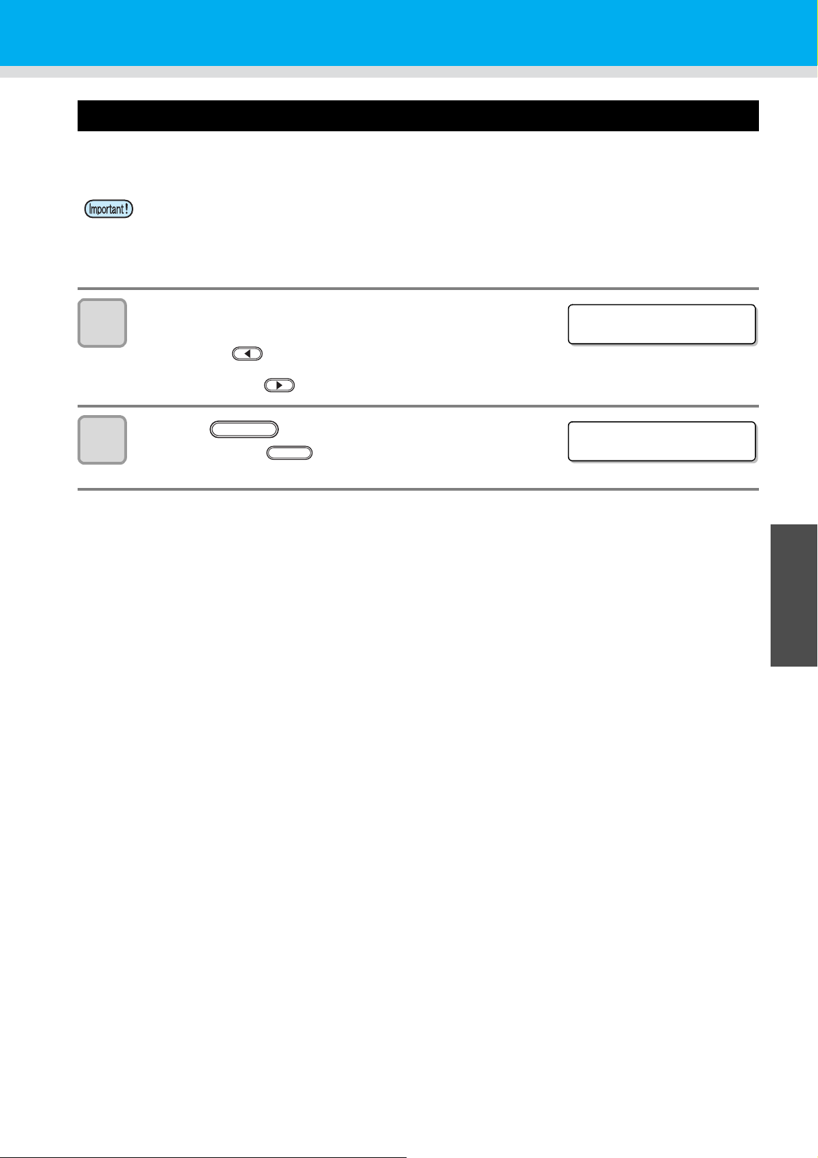
Perform setting to reduce stripes between passes
MAPS 2
PATT ERN : 1
<COLOR >
PATT ERN : 1
ENTER
<COLOR >
SMOOTH I NG L VL : 5 0 %
ENTER
<SPOT>
PATT ERN : 1
ENTER
MAPS 2
スムーシ ゛ ン ク ゛ レヘ ゛ ル : A U T O
<SPOT>
SMOOTH I NG L VL : 5 0 %
ENTER
8
9
10
Press the key.
• When selecting the “AUTO” in the Step 7, back to the step 4.
• When selecting the “MANUAL” in the Step 7, proceed to the step 9.
Set the pattern for the color ink.
(1)Press the keys to select a pattern from pattern 1 to
pattern 6.
(2)Press the
Set the color ink pattern and proceed to Step 10.
(3)Press the key.
Set the color ink pattern and proceed to Step 11.
Set the smoothing for the color ink.
(1)Press the keys to select smoothing level.
•AUTO : Set the smoothing level automatically depending on printing mode.
•5~100% :
(2)Press the key.
Set the color ink smoothing level and proceed to Step 9.
(3)Press the
Set the color ink smoothing level and proceed to Step 12.
ENTER
key.
The MAPS2 effect become strong as the set value increase, and become weak as the set value
decrease.
(set in units of 5%)
key.
11
12
13
Set the pattern for the spot color.
(1)Press the keys to select a pattern from pattern 1 to
pattern 6.
(2)Press the key.
Set the spot color pattern and proceed to Step 12.
(3)Press the
Set the spot color pattern and proceed to Step 9.
Set the smoothing level for the spot color ink.
(1)Press the keys to select smoothing level.
•Press the AUTO:Set the smoothing level automatically depending on printing mode.
•5~100% :
(2)Press the key.
Set the spot color smoothing level and proceed to Step 11.
(3)Press the key.
Set the spot color smoothing level and proceed to Step 10.
Press the key several times to end the setting.
The MAPS2 effect become strong as the set value increase, and become weak as the set value
decrease.
END
key.
(set in units of 5%)
3
Useful Function
3-9
Page 52

Other useful functions
<LOCAL>
DATA CLEAR
<ENT>
ENTER
FW version/ Command information
UJF-3042FX V1.00
MR L
-
III V1.20
Remaining amount of ink
<LOCAL> MCYKW
C
L
REMAIN 999999
<LOCAL>
Data clear
Erase the data not required for this machine with the following operation.
Press the key in the local mode.
DATACLEAR
1
Press the key.
2
• The data is erased.
Displaying information of this machine
The information is displayed sequentially by pressing
1
the key in the local mode.
• The following information are displayed.
Remaining amount of ink / ERROR (If there is an error) / FW version/ Command information
• For the display of remaining amount of ink, the larger number indicates ink remains lot.
• Remaining amount of ink and the remaining number of printing have a margin of error.
Refer the value displayed as a guide.
ENTER
2
Press the key to return to the local mode.
• Information on your machine type can be confirmed in P.3-24 "Displaying machine information".
ENTER
3-10
Page 53
Other useful functions
PR I NT I NG PAUSE
CONT I NUE < >CANCEL
Resume P r i n t
PRESS <ENT > KEY
Proceed with drawing that you suspended
When you open the cover during printing data, drawing is suspended.
In such a case, you can proceed with it continuously by performing the procedures below.
• When you suspended test drawing, you cannot continue it.
• When you proceed with drawing that you suspended, the image quality and the precision may not be
guaranteed.
• When you suspended drawing because an error had occurred, you cannot proceed with it.
When you open the cover during drawing and close it
1
again, the message is displayed.
• Pressing the key displays the message to confirm you whether
you proceed with drawing or not.
• When pressing the key, the machine stops drawing and returns to the local mode.
2
Press the key to proceed with drawing.
• When pressing the key, the screen returns to the one in the
Step 1.
ENTER
END
3
Useful Function
3-11
Page 54
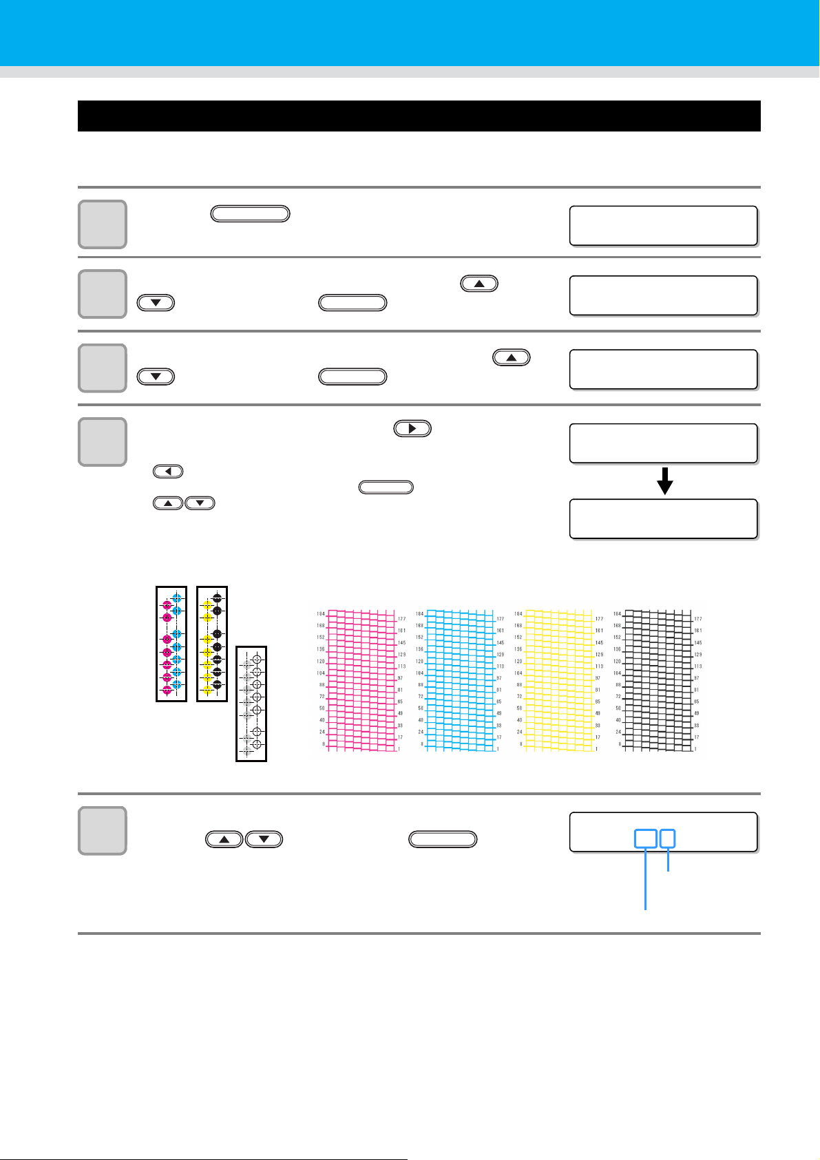
Alternative nozzles for printing, when nozzles missing can not be improved
<LOCAL>
FUNCTION
FUNCT ION
MA I N T ENA NC E < E N T >
MA I N T ENA NC E
NOZ Z L E RECO VER Y <E NT >
NOZ Z L E RECO VER Y
CLEAR< >DRAW
PR I NT I NG
PLEASE WA I T
ENTER
H1
Overhead view
H2
H3
Nozzle pattern
H1-M H1-C H2-Y H2-K
NOZ Z L E RECO VER Y
SELECT : H1 -M
Head No.: H1 to H3
Ink color:
M,C,Y,K,W,CL
NOZZLE RECOVERY: When nozzles missing can not be improved at specific points, other good nozzles can be
used as alternatives for printing.
Press the key in the local mode.
1
Select the [MAINTENANCE] by pressing the or
2
3
key, and press the key.
Select the [NOZZLE RECOVERY] by pressing the or
key, and press the key.
Select the [DRAW] by pressing the key.
ENTER
ENTER
4
• : The set value can be cleared by selecting the Nozzle
line and then pressing key.
• : Select the Nozzle line
“Move to select of the Nozzle line (Step 5) without
drawing a patern”
Select the Nozzle line that needs NOZZLE RECOVERY by
5
3-12
pressing key. Then press key.
ENTER
Page 55

6
NOZ Z L E RECO VER Y
H1 -M NG3 : 146
Registration number:
1 to 5
Recovery nozzle No.:
OFF, 1 to 192
ENTER
Nozzle missing
No.146
Nozzle
number
Nozzle missing
No.12
Nozzle missing
No.102
Example of nozzle to be recovered
Registration
number
Recovery
Nozzle No.
State
112
Target for nozzle recovery
2 102
Target for nozzle recovery
3146
Target for nozzle recovery
4 OFF No registration
5 OFF No registration
Other useful functions
Register the Nozzle number that needs NOZZLE
RECOVERY and then press key.
• : Keys for selecting the registration number from 1 to 5.
• : Keys for registering the nozzle number that needs
recovery from 1 to 192 or selecting “OFF”; no nozzle
registration.
• Up to 5 nozzles can be registered per 1 nozzle line.
• Even if you use this function, time required for drawing does not change.
• For the lowest number of paths of the drawing mode, the NOZZLE RECOVERY function is invalid.
• When you use white ink and clear ink, print on the clear film to check.
3
Useful Function
3-13
Page 56

Other useful functions
<LOCAL>
FUNCTION
FUNCT ION
MA I N T ENA NC E < E N T >
MA I N T ENA NC E
D I SPLACEMENT <ENT>
MA I N T ENA NC E
PR I NT I NG
Checking ink landing displacement
You can check for ink landing displacement from causes such as the equipment table shaking.
(Supported from the firmware ver.3.80)
Press the key in the local mode.
1
Select the [MAINTENANCE] by pressing the or
2
3
4
key, and press the key.
Select the [DISPLACEMENT] by pressing the or
key, and press the key.
Print the pattern for evaluating ink landing on the whole
table.
• When plotting is completed, return to step 3.
ENTER
ENTER
• Ink landing displacement will result in a striped pattern.
Check that the table does not shake and that there is not a large head gap. If there is a larg e ink landing
displacement, request service to readjust the device.
3-14
Page 57
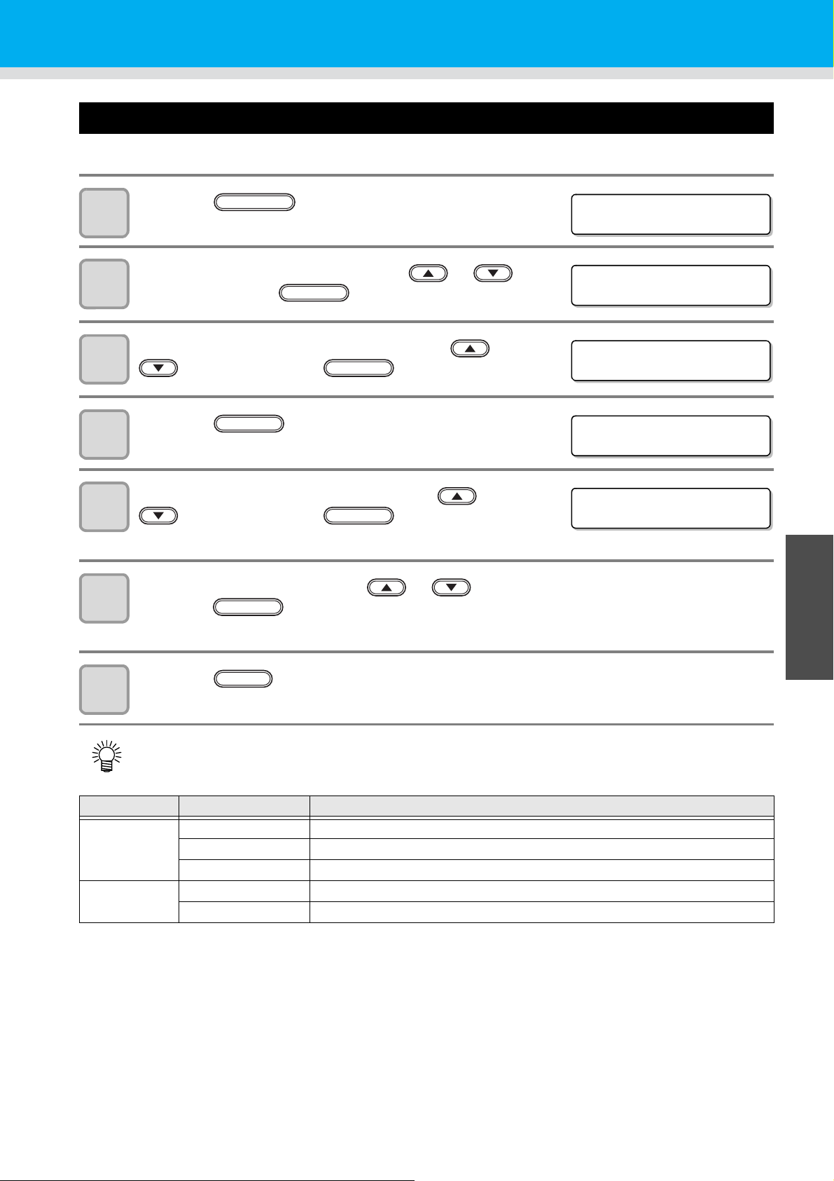
Various settings
<LOCAL>
FUNCTION
FUNC T I ON
WO R K SE T < E N T >
ENTER
SET UP
PR I NT MODE <e n t >
SET UP
QUA L I T Y < e n t >
SET UP
QUA L I T Y : S TAND ARD
ENTER
ENTER
Setting the print method
Set items for printing.
Press the key in the local mode.
1
Select the [SET UP] by pressing the or
2
3
key, and press the key.
Select the [PRINT MODE] by pressing the or
key, and press the key.
ENTER
Press the key.
ENTER
4
Select an item to be set by pressing the or
5
6
key, and press the key.
• As for setting items, see the next page.
Select a value by pressing the or key, and
press the key.
• As for setting values, see the next page.
Press the key several times to end the setting.
END
7
• Set value remains even after turning off the power.
Item Value Outline
QUALITY STANDARD Standard draw ing quality
FINE High quality drawing (drawing speed is slower)
FAST High speed drawing (quality is inferior)
LOGICAL
SEEK
ON The head moves according to the data width to be drawn.
OFF The head moves whole table width at drawing.
3
Useful Function
3-15
Page 58
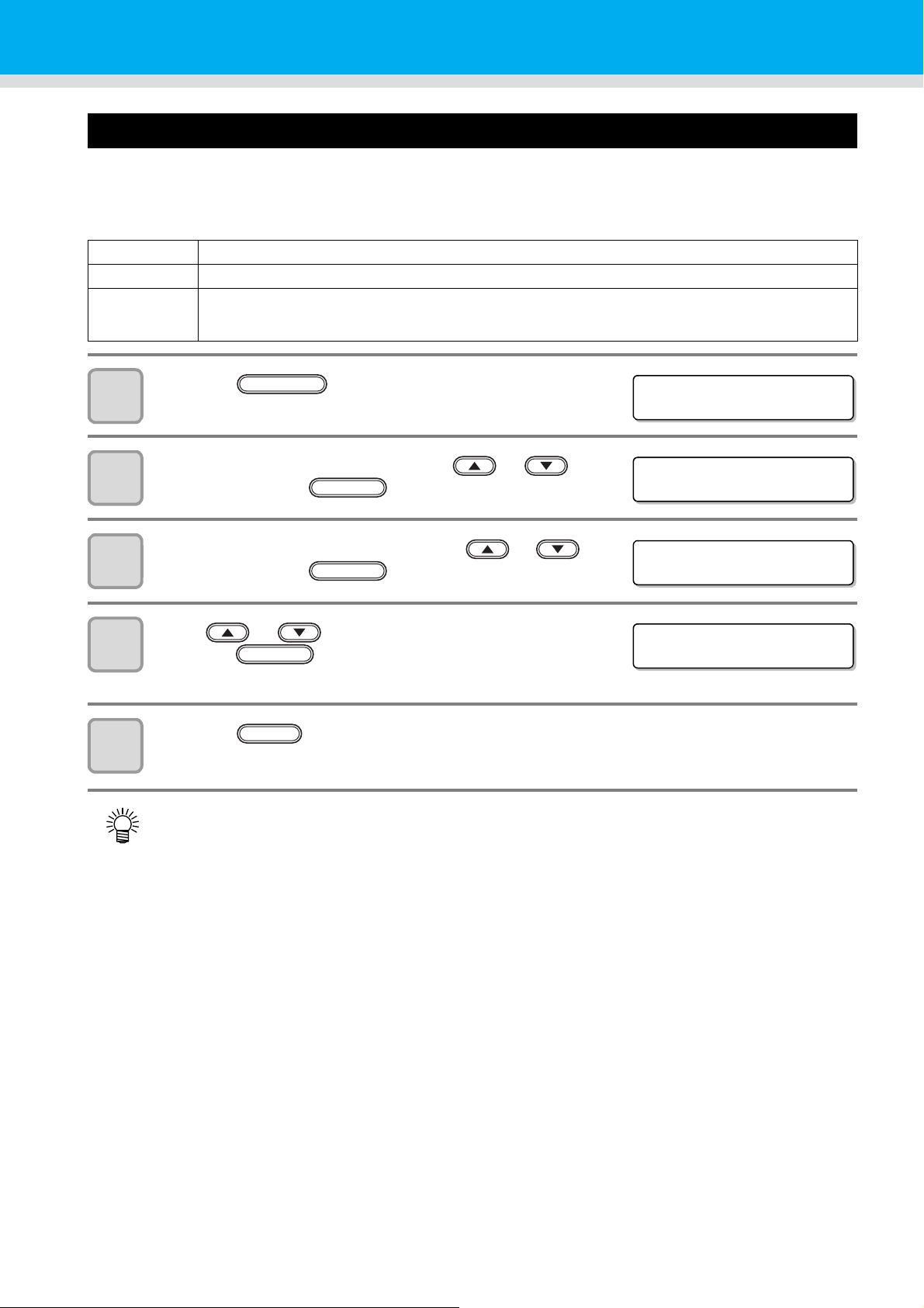
Setting the mode of the LED UV
<LOCAL>
FUNCTION
FUNC T I ON
WO R K SE T < E N T >
ENTER
SET UP
UV MODE <e n t >
ENTER
SET UP
UV MODE : ON
ENTER
The mode of the LED UV may be set in 3 stages.
This setting is made when the media vulnerable to the heat is used or when the test drawing is made in which the
lighting of the LED UV is not desired.
ON The LED UV is lit.
OFF The LED UV is not lit.
NOPRINT
1
2
3
4
5
The drawing is not performed and only the LED UV is lit. Use when drawing is performed without the LED
UV is lit etc., and when you wish to make it cure afterward. (Normally, this setting will not be made.)
Press the key in the local
mode.
Select the [SET UP] by pressing the or
key, and press the key.
Select the [UV MODE] by pressing the or
key, and press the key.
Press or keys to select the mode, and
press the key.
• Set values :ON , OFF , NOPRINT
Press the key several times to end the setting.
END
• The mode of the LED UV may be set on the RIP side, when performing the remote drawing. For details,
please refer to the Instruction Manual of your RIP.
3-16
Page 59

Various settings
<LOCAL>
FUNCTION
FUNC T I ON
WO R K SE T < E N T >
SET UP
UV Cur ing Level<ent>
SET UP
UV Cu r i ng Le ve l : 0
END
Increasing cumulative UV irradiation when the number of passes is low
When the number of passes is low (720x600: 8 passes or less, 720x900: 12 passes or less, 720x1200: 8 pa sse s
or less), cumulative UV light quantity irradiated to th e disc harg ed in k is smaller, which may cause insufficient UV
curing for some media type.
Setting [UV Curing Level] reduces the number of nozzles to be used when the number of passes is low.
Increasing the scan count increases the cumulative UV light quantity. (Supported from the firmware ver.3.80)
Press the key in the local mode.
1
Select the [SET UP] by pressing the or key,
2
3
and press the key.
Select the [UV Curing Level] by pressing the or
key, and press the key.
ENTER
ENTER
4
5
Select curing level to be set by pressing the or
key, and press the key.
• Set value: 0(default), 1, 2, 3
Press the key several times to end the setting.
• This operation is available only when the number of passes is low (720x600: 8 passes or less, 720x900:
12 passes or less, 720x1200: 8 passes or less). In other drawing modes, the number of nozzles used
normally are used for drawing.
• Due to a reduced number of nozzles used for drawing, the drawing time becomes longer.
ENTER
3
Useful Function
3-17
Page 60

Setting of priority
<LOCAL>
FUNCTION
FUNC T I ON
WO R K SE T < E N T >
ENTER
SET UP
PR IOR I TY <e n t >
ENTER
SET UP
PR IOR I TY : AL L HOST
ENTER
SET UP
PR INT MODE : PLOT
ENTER
ENTER
Select priority of setting of this machine or that of the computer on the following items respectively.
Items to be selected : Print mode / Feed compensation / Ink layers / Logical seek / Refresh
Press the key in the local mode.
1
Press the [SET UP] by pressing the or
2
3
4
key, and press the key.
Select the [PRIORITY] by pressing the or
key, and press the key.
Select the set value by pressing the or
key, and press the key.
• Set value: ALL HOST / ALL PLOT / INDIVIDUAL
• If you select [ INDIVIDUAL ], go to the Step 5, and if you select others, go to the Step 7.
5
6
7
Select the “HOST” or the “PLOT” by pressing the
or key, and press the key.
• Although the item can be selected by pressing the or
key, be sure to press the key to save the setting.
Set other items with the same manner as 4, 5.
Press the key several times to end the setting.
• If there is no indication from the host when Host has priority, the setting of PLOT is effective.
END
3-18
Page 61

Setting the mode of the fan mode
<LOCAL>
FUNCTION
FUNC T I ON
WO R K SE T < E N T >
ENTER
SET UP
FAN MODE <en t >
SET UP
FAN MODE : AUTOMATIC
ENTER
END
Set whether you perform vacuum automatically or with the user-specified operation.
When you set it to “AUTO”, vacuum is made to ON automatically before drawing.
When you set it to “MANUAL”, ON/OFF of vacuum follows the user setting.
(Supported from the firmware ver.3.00)
Press the key in the local
1
2
3
mode.
Select the [SET UP] by pressing the or
key, and press the key.
Select the [FAN MODE] by pressing the or
key, and press the key.
ENTER
Various settings
4
5
Select the set value by pressing the or
key, and press the key.
• Set values :AUTOMATIC, MANUAL
Press the key several times to end the setting.
3
Useful Function
3-19
Page 62
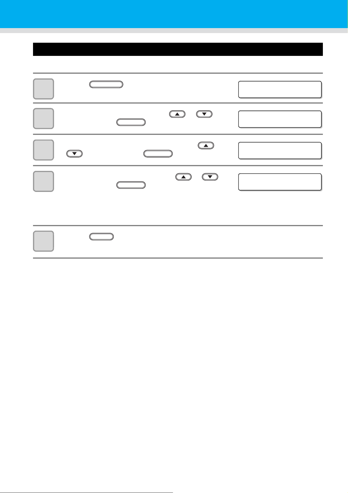
Setting the work change
<LOCAL>
FUNCTION
FUNC T I ON
WO R K SE T < E N T >
ENTER
SET UP
WO R K CHAN GE < e n t >
ENTER
SET UP
WO R K CHAN GE : OF F
ENTER
Set whether to return to the local mode or keep the remote mode after online drawing.
Press the key in the local mode.
1
Press the [SET UP] by pressing the or
2
3
4
key, and press the key.
Select the [WORK CHANGE] by pressing the
or key, and press the key.
Select “OFF” or “ON” by pressing the or
key, and press the key.
• OFF: Keeps the remote mode after online drawing.
(draws next drawing data over a drawn face while receiving)
• ON: Returns to the local mode after online drawing.
5
Press the key several times to end the setting.
END
3-20
Page 63

Various settings
<LOCAL>
FUNCTION
FUNC T I ON
WO R K SE T < E N T >
ENTER
SET UP
CART WEI GHT <en t >
SET UP
CARTR I DGE : M
SET UP
WE I GH T = 8 5 0 g
ENTER
SET UP
850g OK? :ent
ENTER
END
Setting the ink weight
Enter the weight when after filling ink or INK LVL LOW or INK LVL END is detected. This machine recalculates
remaining amount of ink and writes the value into the IC chip. (600ml ink only)
Press the key in the local mode.
1
Press the [SET UP] by pressing the or
2
3
key, and press the key.
Select the [CART WEIGHT] by pressing the or
key, and press the key.
Select cartridges by pressing the or key.
ENTER
4
• The ink colors of the cartridges displaying “INK LVL LOW” or “INK LVL END” are displayed as
“MCYKW
• When two cartridges of the same color are set as WW or
C
”.
L
CLC
, they are displayed as W1W2 or
L
C
C
1
2.
L
L
5
6
7
Enter weight of the cartridge by pressing the
or key, and press the key.
• The number changes by 1 g.
Fix or change the setting.
• Press the key to fix the setting.
• Press the key to change the weight (back to Step 5).
Press the key several times to end the setting.
END
3
Useful Function
3-21
Page 64
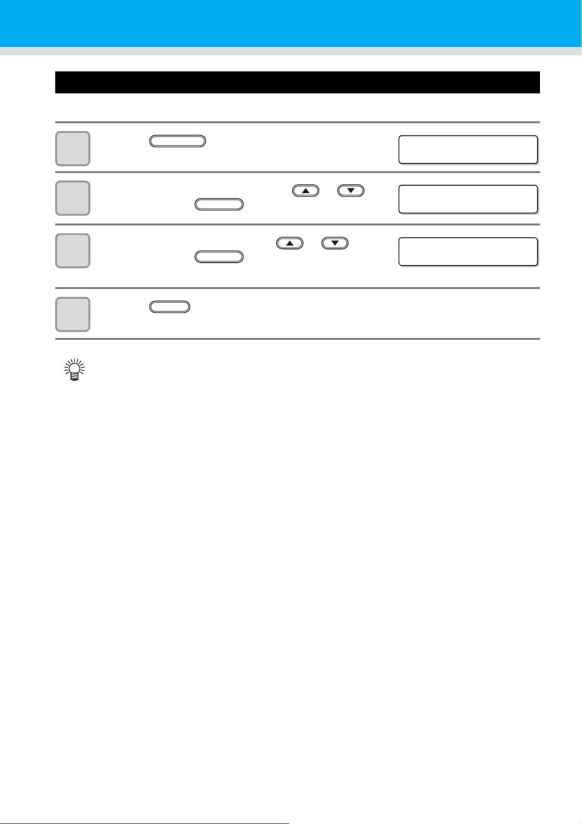
Changing language display on the screen
<LOCAL>
FUNCTION
FUNC T I ON
DISPLAY <ENT>
ENTER
DISPLAY
Eng l i sh <en t>
ENTER
Display language can be selected between Japa ne se an d Eng lish .
Press the key in the local mode.
1
Select the [DISPLAY] by pressing the or
2
3
key, and press the key.
Select a language by pressing the or
key, and press the key.
• Default is “English.”
4
Press the key to finish.
• Set value remains even after turning off the power.
END
3-22
Page 65
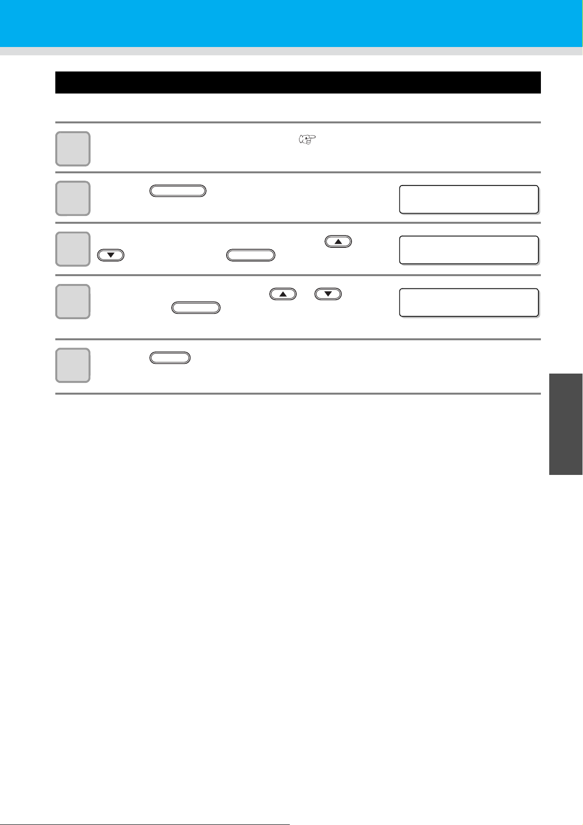
Output the setting list
<LOCAL>
FUNCTION
FUNC T I ON
MA I N TE NANC E < EN T >
ENTER
MA I N TE NANC E
LIST <ent>
Keep the list for customer’s record or send it by the fax at inquiry on the maintenance.
Set a larger media than the legal size. ( P.2-4)
1
Press the key in the local mode.
2
Select the [MAINTENANCE] by pressing the or
3
4
key, and press the key.
Select the [LIST] by pressing the or key,
and press the key.
• Output of the setting list starts.
ENTER
Various settings
5
Press the key to finish.
END
3
Useful Function
3-23
Page 66
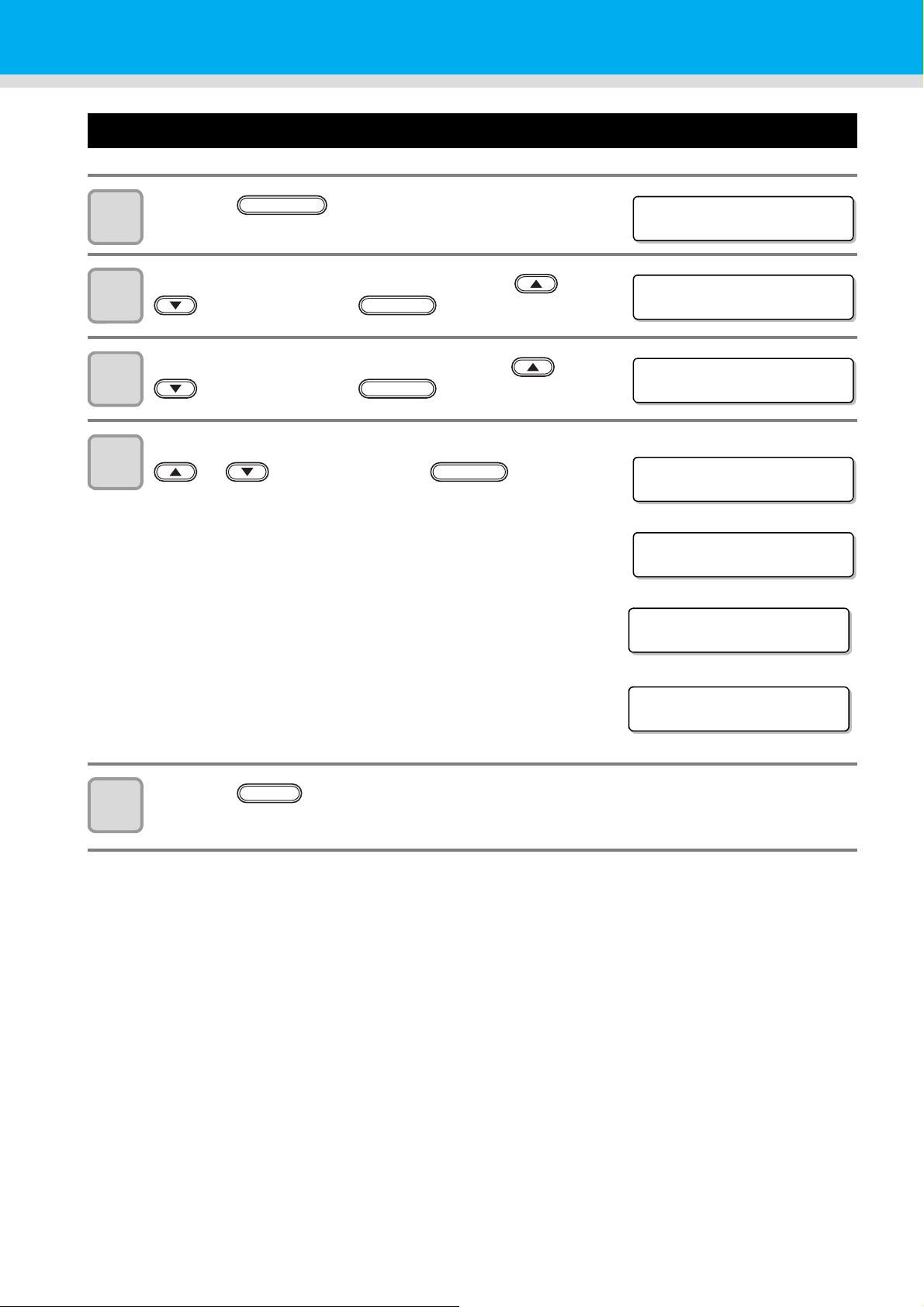
Displaying machine information
<LOCAL>
FUNCTION
FUNC T I ON
MA I N TE NANC E < EN T >
MA I N TE NANC E
INFORMATION <ent>
Version information
Serial No. information
MA I N TE NANC E
MA I N V e r 1 . 0 0
MA I N TE NANC E
S/N 00000000
Head serial No. information
MA I N TE NANC E
Head 1111-111111J
Error history
[00000]
2014/01/
2 312:34:56
ENTER
Press the key in the local mode.
1
Select the [MAINTENANCE] by pressing the or
2
3
4
key, and press the key.
Select the [INFORMATION] by pressing the or
key, and press the key.
Select information to be displayed by pressing the
or key, and press the key.
• The following 3 information can be displayed.
FW version of this machine
Serial No.
Head serial No. (Supported from the firmware ver.3.90.)
Error history (Supported from the firmware ver.4.00.)
ENTER
ENTER
Press the key several times to end the setting.
5
END
3-24
Page 67

About Displayed Information
[00000]
2014/01/23 12:34:56
[00001]
2014/01/23 01:23:45
ERROR 6 0 2
INK END
key: Displays an error that occurred more recently.
key: Displays an error that occurred further in the past.
• The smaller the number at the top left,
the more recently the error occurred.
The error occurrence date and
error message are displayed
alternately.
This section describes how to read displayed information.
ERROR HISTORY
Displaying the
occurrence date
Various settings
3
Useful Function
3-25
Page 68
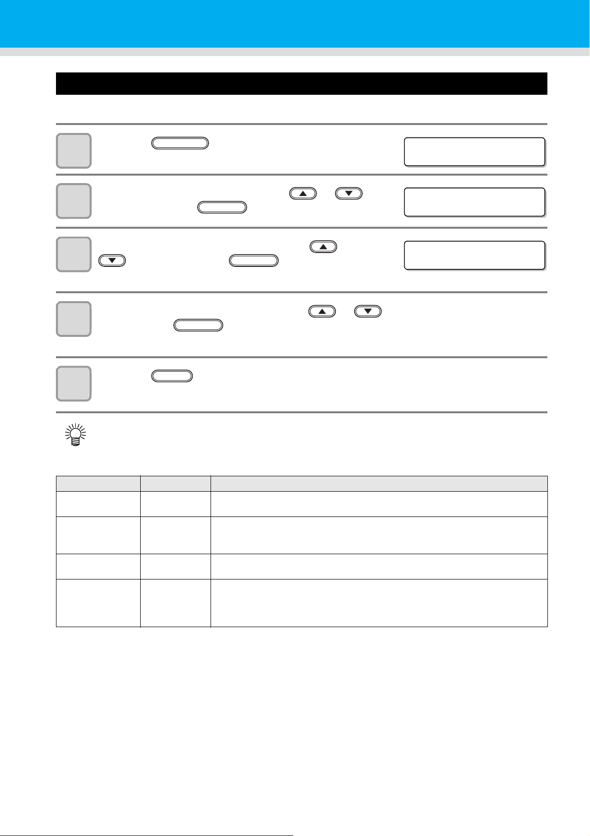
Other useful settings
<LOCAL>
FUNCTION
FUNC T I ON
WO R K SE T < E N T >
ENTER
SET UP
I NK LAYERS <en t >
Change settings according to need.
Press the key in the local mode.
1
Select the [SET UP] by pressing the or
2
3
4
key, and press the key.
Select an item to be set by pressing the or
key, and press the key.
• Select with reference to the Table of Setting below.
Select a value to be set by pressing the or key ,
and press the key.
• Select with reference to the Table of Setting below.
ENTER
ENTER
Press the key several times to end the setting.
END
5
• Set value remains even after turning off the power.
Table of Setting
Item Value Outline
INK LAYERS 1 to 9 times Set the number of times for over painting.
Finer drawing can be obtained by over painting.
REFRESH Level 0 to 3 Set the refreshing revel for preventing the head from clogging in a dusty
environment.
The larger level number indicates more frequent refreshing times.
UV AddScan OFF ,
1 to 15 times
AUTO CLEANING ON, OFF Set whether auto-head cleaning is executed or not at the following intervals before
Designates the number of times of additional scanning of UV to cure the edge parts
of the image with UV irradiation after completion of the drawing.
drawing.
• After the proper drawing for the refresh level after the previous cleaning and
before drawing next data
3-26
Page 69
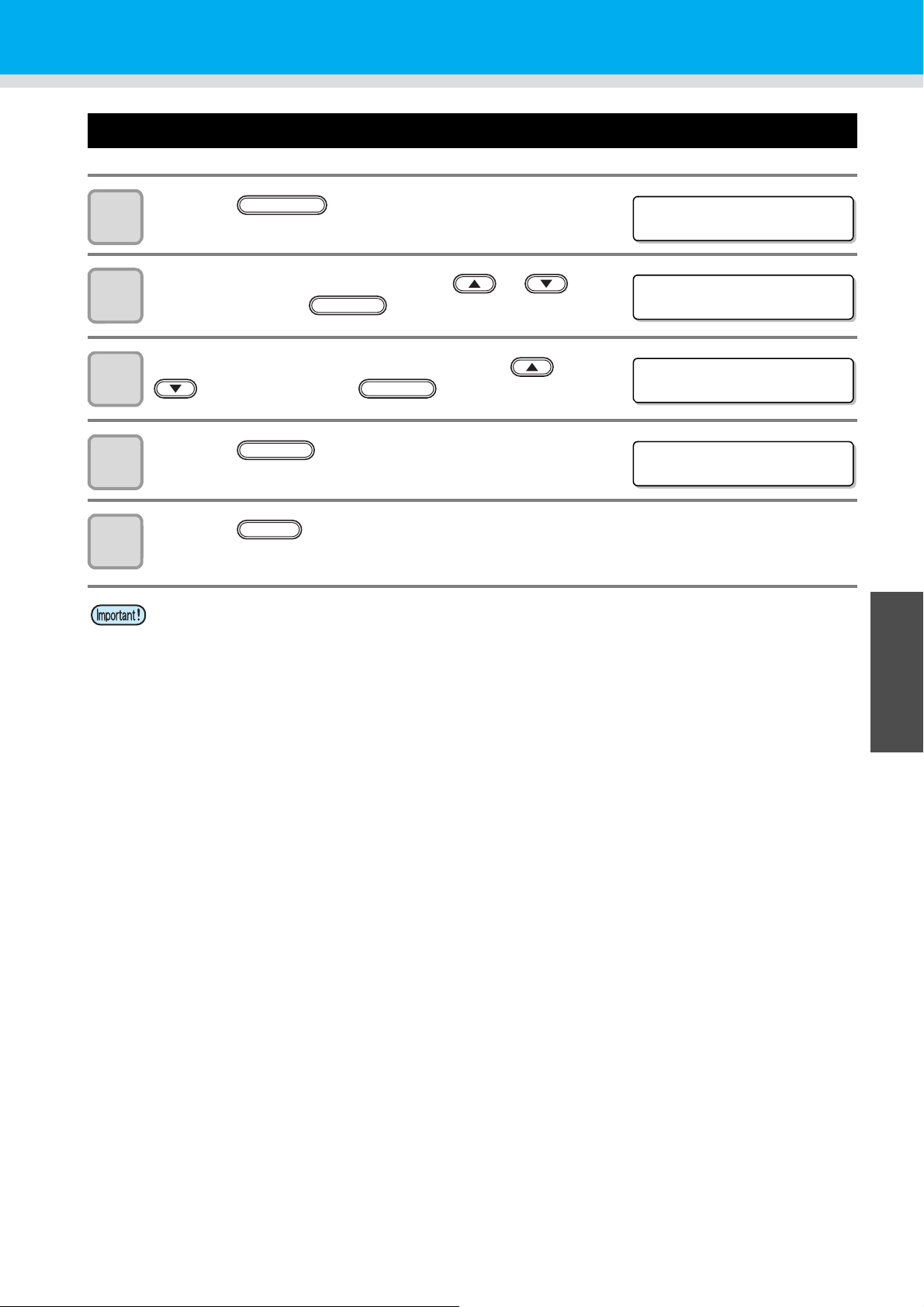
Initializing settings
<LOCAL>
FUNCTION
FUNC T I ON
WO R K SE T < E N T >
ENTER
SET UP
SETUP RESET <e n t>
SET UP
INITIAL. OK? :ent
Press the key in the local mode.
1
Select the [SET UP] by pressing the or
2
3
key, and press the key.
Select the [SETUP RESET] by pressing the or
key, and press the key.
Various settings
ENTER
4
5
Press the key.
• Resets the setup.
Press the key several times to end the setting.
• In the [SETUP RESET], resetting is allowed only on contents changed in the settings.
ENTER
END
3
Useful Function
3-27
Page 70

Setting time
<LOCAL>
FUNCTION
FUNC T I ON
MAC H I N E SE T < EN T >
MAC H I N E SE T
SET T IME <en t >
ENTER
SET T IME
DATE= 20
0 9 .01.05
SET T IME
TIME=
1 0 :20:00
SET T IME
DATE= 20
0 9 .01.05
ENTER
Press the key in the local mode.
1
Select the [MACHINE SET] by pressing the or
2
key, and press the key.
Press the key twice.
3
Set time by pressing the key.
4
• Selecting date (year/month/date/hour/minute): use .
• Entering date (year/month/date/hour/minute): use .
ENTER
5
6
Press the key.
• The entered date is displayed.
• “0” is displayed on the field of second.
Press the key several times to end the setting.
• For the past time, up to 8 hours before now is settable.
• For the future time, up to 24 hours from now is settable.
END
3-28
Page 71
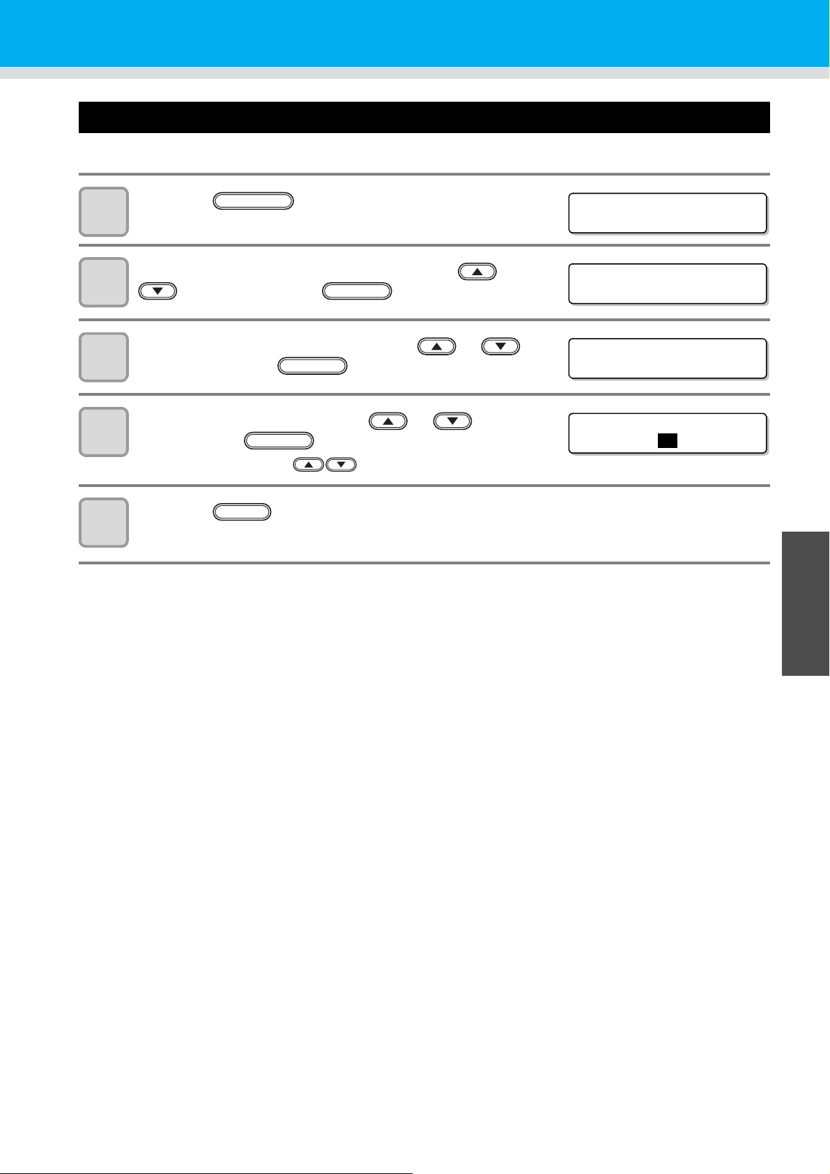
Setting mm/ inch
<LOCAL>
FUNCTION
FUNC T I ON
MAC H I N E SE T < EN T >
MAC H I N E SE T
MM / I N C H < e n t >
ENTER
MAC H I N E SE T
MM / I N C H :
MM
Set the unit to be used on this machine.
Press the key in the local mode.
1
Select the [MACHINE SET] by pressing the or
2
3
4
key, and press the key.
Select the [MM/INCH] by pressing the or
key, and press the key.
Select the unit by pressing the or key,
and press the key.
• Setting of the unit : use .
ENTER
Various settings
ENTER
5
Press the key several times to end the setting.
END
3
Useful Function
3-29
Page 72

Setting weight of the empty cartridge
<LOCAL>
FUNCTION
FUNC T I ON
MAC H I N E SE T < EN T >
MAC H I N E SE T
600ml CARTRIDGE<ent>
ENTER
MAC H I N E SE T
CARTR I DGE : M
MAC H I N E SE T
CASE WEIGHT =300g
ENTER
Enter weight of the empty cartridge. It is used for recalculating remaining amount of ink. (600ml ink only)
Press the key in the local mode.
1
Press the [MACHINE SET] by pressing the or
2
3
key, and press the key.
Select the [600ml CARTRIDGE] by pressing the
or key, and press the key.
Select cartridges by pressing the or key.
ENTER
4
• The ink colors set in the cartridges are displayed as “MCYKW
• When two cartridges of the same color are set as WW or
C
”.
L
CLC
, they are displayed as W1W2 or
L
C
C
1
2.
L
L
5
6
Enter weight of the cartridge by pressing the
or key, and press the key.
• The number changes by 1 g.
Press the key several times to end the setting.
END
3-30
Page 73

Setting Key buzzer
<LOCAL>
FUNCTION
FUNC T I ON
MAC H I N E SE T < EN T >
MAC H I N E SE T
KEY BUZZ
E R<ent>
MAC H I N E SE T
KEY BUZZ
E R:O F F
END
Set the buzzer sound when keys are pressed.
Press the key in the local mode.
1
Select the [MACHINE SET] by pressing the or
2
3
4
key, and press the key.
Select the [KEY BUZZER] by pressing the or
key, and press the key.
Select ON/OFF by pressing the or key,
and press the key.
ENTER
ENTER
ENTER
Various settings
5
Press the key several times to end the setting.
• The sound of Error /Warning /Operation completed cannot be set off even if the setting above is “OFF”.
3
Useful Function
3-31
Page 74
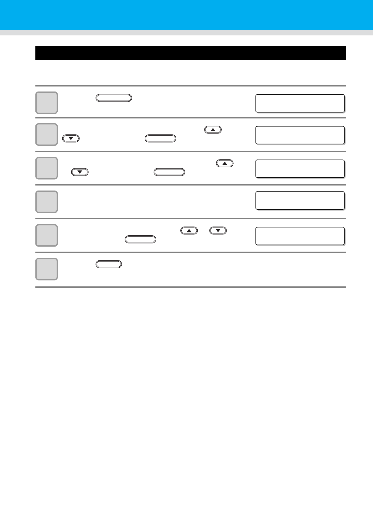
Setting radiator pump
<LOCAL>
FUNCTION
FUNC T I ON
MAC H I N E SE T < EN T >
MAC H I N E SE T
RAD I ATOR PUMP < en t >
ENTER
MAC H I N E SE T
PUMP : T ype A
MAC H I N E SE T
PUMP : T ype B
ENTER
On UJF-3042 and UJF-3042FX, if the noise of the cooling pump for LED UV unit become louder after updating
the firmware to the version 3.10 or later, change the setting as follows. (Supported from the firmware ver.3.10)
Press the key in the local mode.
1
Press the [MACHINE SET] by pressing the or
2
3
key, and press the key.
Select the [RADIATOR PUMP] by pressing the
or key, and press the key.
The current pump type is displayed.
ENTER
4
Select the [Type B] by pressing the or
5
key, and press the key.
6
Press the key several times to end the setting.
END
3-32
Page 75
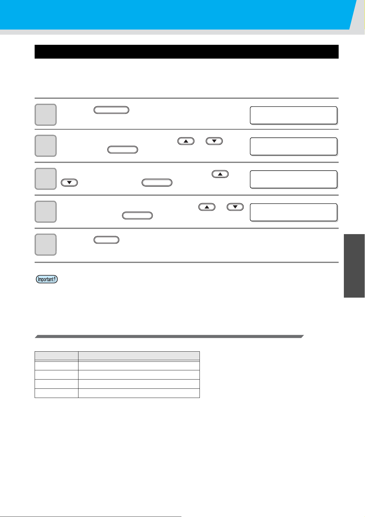
Various settings
<LOCAL>
FUNCTION
FUNC T I ON
SET UP <ENT>
SET UP
PR I NT FLUSH I NG <ENT >
SET UP
MOD E : L e v e l 0
ENTER
Setting the flushing level before printing
When using a clear acrylic jig and so on, the ink may splash on the print result as the ink on the nozzles thickens
due to stray light.
If this happens, increase the flushing amount before printing to prevent ink from splashing. (Supported from the
firmware ver.4.00)
Press the key in the local mode.
1
Press the [SET UP] by pressing the or key,
2
3
and press the key.
Select the [PRINT FLUSHING] by pressing the or
key, and press the key.
ENTER
ENTER
Select print flushing level by pressing the or
4
key, and press the key.
Press the key several times to end the setting.
END
5
• If you are using the printer in an environment subject to stray light, select level 2. Level 2 uses the same
flushing amount as cleaning.
If the same error still occurs, change the setting to level 3.
If you can print without problem in level 2 and you are concerned about the amount of ink consumed,
change the setting to level 1.
Setting list
For the amount of ink consumed for each level, see the following.
Level Amount of ink consumed (per color)
0 0.03cc
10.06cc
20.12cc
30.18cc
3
Useful Function
3-33
Page 76

3-34
Page 77

CHAPTER 4
Maintenance
Items required for using this machine conveniently, such as an
ink replacing method or a cleaning manner, are described.
Routine maintenance........................... 4-2
When this machine is left unused
for a long time ...........................................4-2
Precautions in cleaning ............................4-2
Cleaning exterior surfaces ........................4-3
Cleaning the table ....................................4-3
Ink cartridge.......................................... 4-4
Replacing with a new ink cartridge ...........4-4
Setting the ink set .....................................4-5
Ink cartridge trouble ..................................4-8
Shaking the white ink cartridge ................4-9
600ml Ink cartridge............................. 4-10
Registering the case weight ...................4-10
Registering the cartridge weight .............4-11
Registering the cartridge weight
(After LVL LOW / LVL END) ...................4-12
Avoiding dripping of ink droplet
at printing............................................ 4-13
When the waste ink is full.................. 4-15
Disposing of the ink in the waste ink tank
Disposing of the waste ink
in the wiper bottle ...................................4-17
Replacing the Filter............................ 4-19
Washing the Nozzle............................ 4-21
Wash the ink discharge passage...... 4-23
When the Machine Is Not Used for a Long
Time (CUSTODY WASH).................... 4-25
Washing the Head .............................. 4-27
Perform ink filling............................... 4-29
Setting nozzle face cleaning time..... 4-30
Regular maintenance for white ink... 4-31
Cleaning of wiper................................ 4-33
Refilling antifreeze mixed water........ 4-35
Refilling antifreeze mixed water ..............4-36
..4-15
Page 78

Routine maintenance
Be sure to conduct maintenance works for the machine de pending on opera tion frequency or perio dically so as to
use the machine for a long time while keeping its drawing accuracy.
When this machine is left unused for a long time
• Be sure to turn off the main power switch on the side of this machine. ( P.1-4)
• Remove the media being set.
Precautions in cleaning
• Never disassemble this machine. Disassembling this machine can result in electric shock hazards or
damage to this machine.
• Prevent moisture from entering this machine. Moisture inside the machine can result in electric shock
hazards or damage to this machine.
• Before starting maintenance work, be sure to turn off the main power switch and unplug the power cable;
otherwise, an unexpected accident may occur.
• Do not use benzine, thinner, or any chemical agent containing abrasives. Such materials can deteriorate
or deform the surface of the covers.
• Do not apply lubricating oil or the like to any part inside this machine. Such materials can cause this
machine mechanism to fail.
• In case water or alcohol mixed into the UV curing ink (UV ink), flocculation would be occurred.
Be sure not to adhere water or alcohol not only on the nozzle and also near the head.
• This machine uses UV curing ink (UV ink). When in daily care, pay close attention to ventilation and be
sure to wear the included safety glasses and gloves.
4-2
Page 79

Routine maintenance
Cleaning exterior surfaces
If exterior surfaces of the machine is dirty, dampen a soft cloth with water or a neutral detergent diluted with
water, squeeze it and wipe the surfaces.
Cleaning the table
The table is easy to become dirt with lint, paper dust or the like after cutting media.
For a conspicuous stain, wipe it off with a soft-hair brush, a dry cloth, a paper towel or the like.
• Do not allow liquids to get inside the product. Ingress of liquids into the product may lead to failure,
electric shock, or fire.
• For heavy soiling, wipe using a soft cloth soaked in dilute detergent and thoroughly wrung out.
• Be sure to clean the slot on the frame of the table, the screw holes for holding tools or the like since dust
and dirt are easily accumulated in these parts.
• If it is stained with ink, wipe it off with a paper towel containing a little amount of the cleaning solution.
4
Maintenance
4-3
Page 80
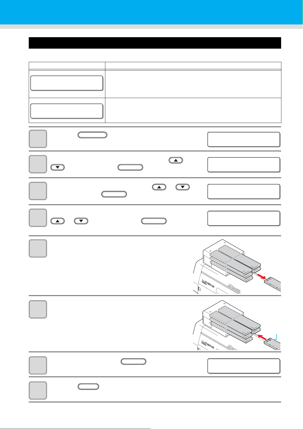
Ink cartridge
<LOCAL>
INK NEND M_____
<LOCAL>
INK END M_____
<LOCAL>
FUNCTION
FUNC T I ON
MA I N TE NANC E < EN T >
ENTER
MA I N TE NANC E
STAT ION <en t>
ENTER
STAT ION
MENT : EXCH CARTR I DGE
ENTER
IC chip
STAT ION
COMPL E TE D : e n t
Replacing with a new ink cartridge
Replacing of ink cartridges is required in the following cases.
Display Outline
The ink in the ink cartridge is low.
• Drawing can be continued, but the ink may end during the drawing. Early
replacement is recommended.
• The display shown in the left indicates that magenta ink is low.
The ink in the ink cartridge ended.
• Unable to continue drawing. Replace with a new one immediately.
• The display shown in the left indicates that magenta ink ended.
Press the key in the local mode.
1
Select the [MAINTENANCE] by pressing the or
2
key, and press the key.
3
4
5
6
Select the [STATION] by pressing the or
key, and press the key.
Select the [EXCH CARTRIDGE] by pressing the
or key, and press the key.
• Y-bar moves to the front.
Remove an ink cartridge to be replaced.
Set a new ink cartridge
• As shown in the drawing, set an ink cartridge turning up a side
containing the IC chip.
After replacing, press the key.
7
• Y-bar returns to the back.
Press the key to finish.
8
4-4
ENTER
END
Page 81
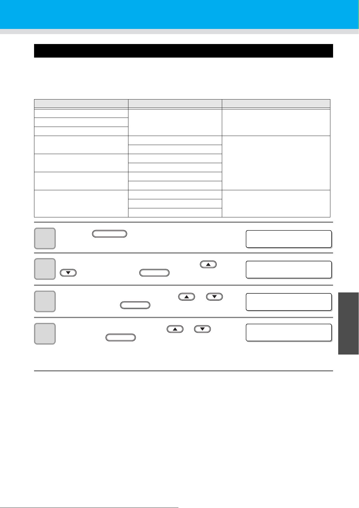
Ink cartridge
<LOCAL>
FUNCTION
FUNC T I ON
MA I N TE NANC E < EN T >
MA I N TE NANC E
INK SET <ent>
ENTER
INK SET [LH-100]
SELECT : MCYKW
C
L
Setting the ink set
Set the ink set when ink type is changed. Contact a distributor in your district or our office to call for service.
When you replace another kind of ink, wash all heads.
For replacement between the same inks, the process (washing and filling) flow is as below:
Ink set before replacement Ink set after replacement Procedure
CLC
CLC
C
L
L
C
L
L
MCYK_ _ Third head washing only
MCYKWW Third head fill up after washing
CLC
MCYK
MCYK
MCYKW
MCYKWW
MCYKWW
MCYK
CLC
CLC
L
C
L
L
C
L
C
L
L
Third head filling only
MCYKW
MCYKWW
MCYK
MCYKW
MCYKWW MCYKW
MCYK
MCYK_ _ MCYKW
1
2
3
4
Press the key in the local mode.
Select the [MAINTENANCE] by pressing the or
key, and press the key.
ENTER
Select the [INK SET] by pressing the or
key, and press the key.
Select the ink set by pressing the or key ,
and press the key.
• Select from the following sets of ink.
MCYKW
• When the ink set is changed, go to the next step.
C
L
ENTER
/ MCYKWW / MCYK
CLC
/ MCYK_ _
L
4
Maintenance
4-5
Page 82
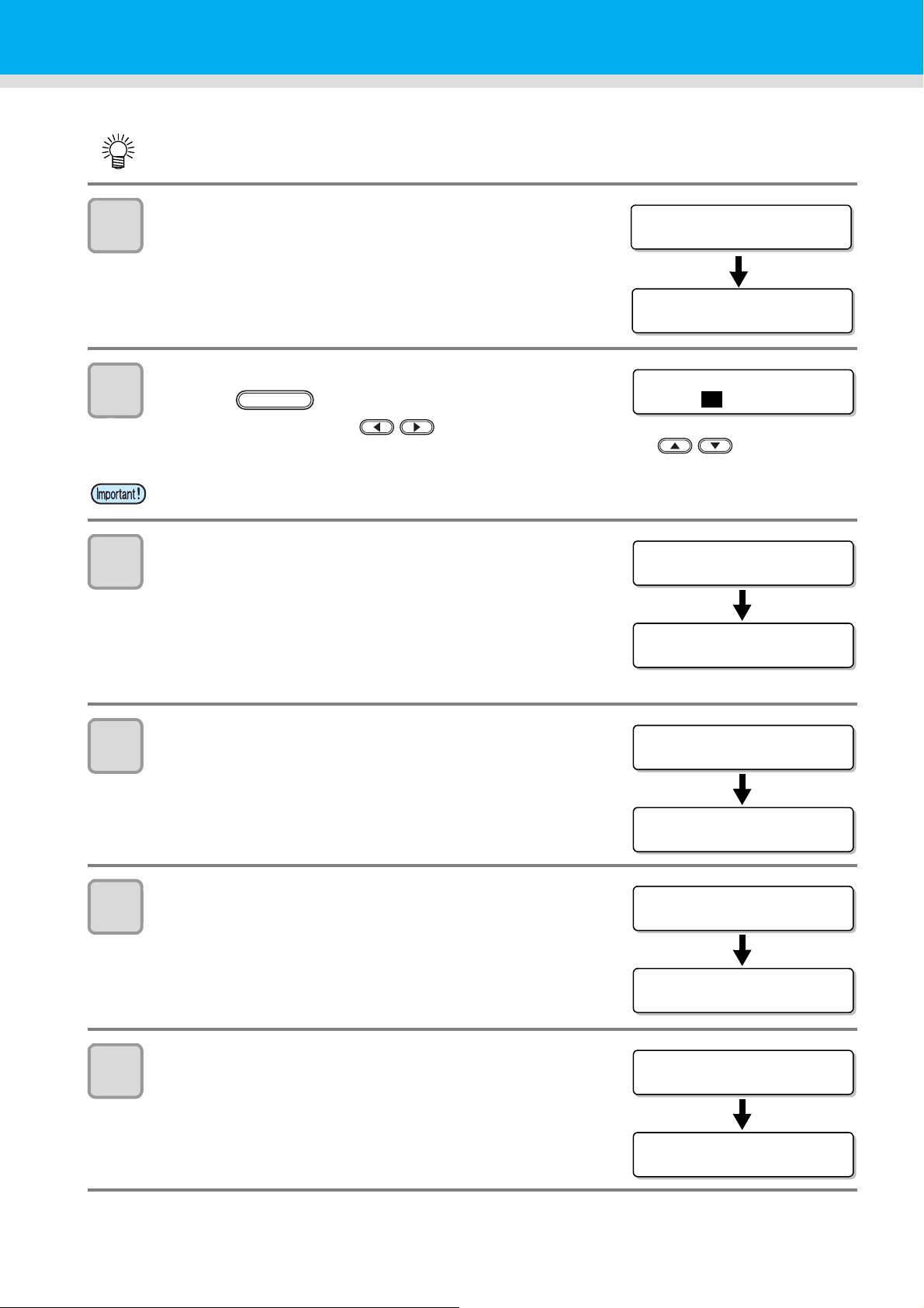
5
WA S H
REMOVE CARTR I DGE
WA S H I NG
PLEASE WAI T
WA S H I NG
HEAD [
MC YKW
C
L
]
ENTER
WASH ____W
C
L
SET WASH ING L IQUI D
WA S H I NG
PLEASE WAI T
WASH ____W
C
L
REMOVE CARTR I DGE
WA S H I NG
PLEASE WAI T
WASH ____W
C
L
SET WASH ING L IQUI D
WA S H I NG
PLEASE WAI T
WASH ____W
C
L
REMOVE CARTR I DGE
WA S H I NG
PLEASE WAI T
6
7
• The step 5 to 10 is displayed when washing is required.
Pull out the ink cartridges from the ink station.
• When the ink cartridges are pulled out, ink discharge
operation starts.
Select washing the head or not for each head, and
press the key.
(1)Select the head with the key.
(2)Select washing (displays the head No.) or not (displays “_”) with the key.
• When a color set on the head or the ink type is changed, be sure to perform Head Washing.
When a screen shown on the right is displayed, set
the washing liquid cartridge (SPC-0516FS) to the ink
station.
8
9
10
• Head washing starts.
• Repeat the Step 7 to 8 for each head to wash.
Remove the washing liquid cartridge.
Set the washing liquid cartridge to the ink station
again.
Remove the washing liquid cartridge.
4-6
Page 83
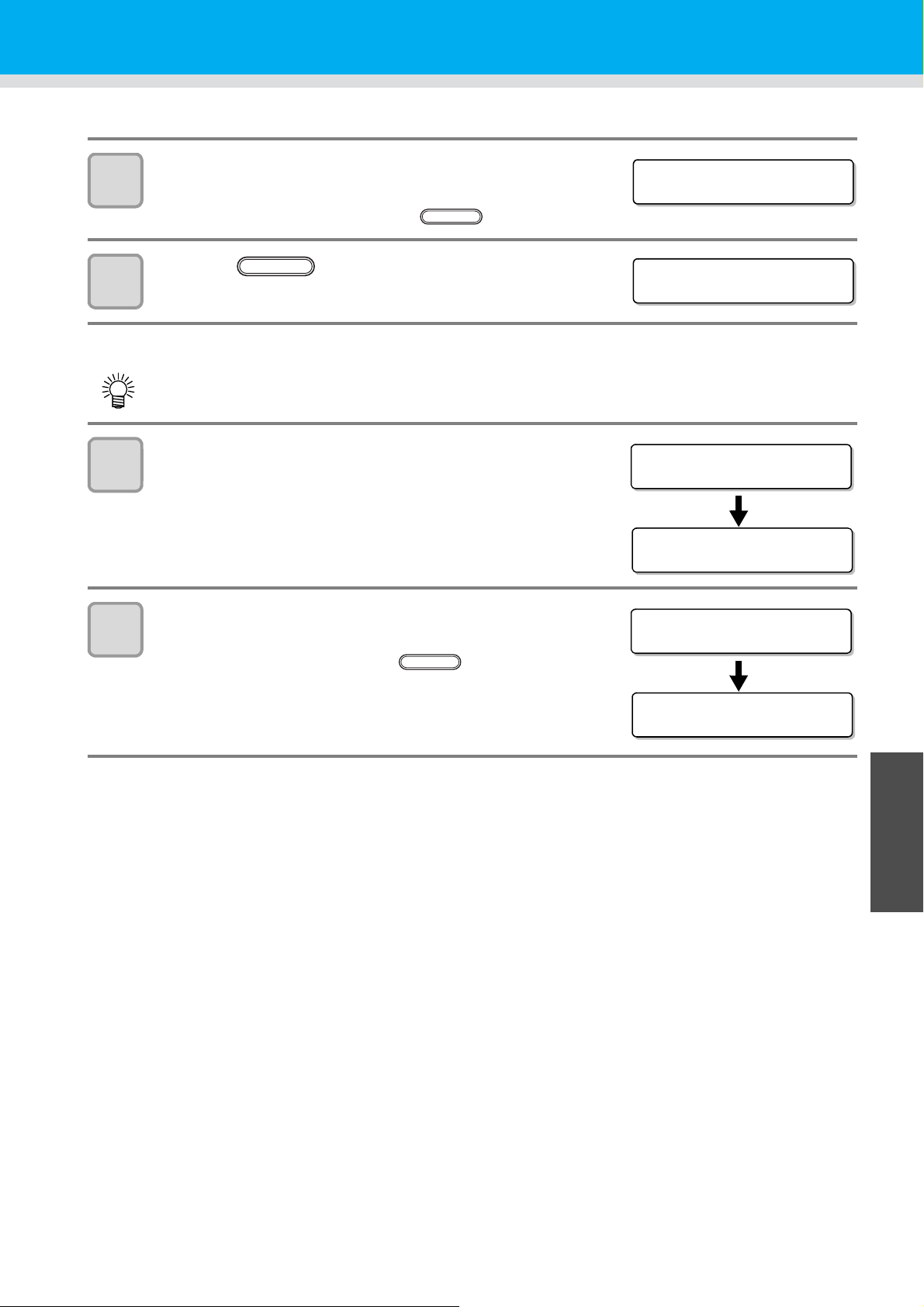
11
TUBE CLEANING
COMPL E TE D : e n t
ENTER
WA S H
COMPL E TE D : e n t
FILL UP INK ____WW
SET CARTRI DGE
FILL UP
***-----------------
FILL UP INK
Please def late :ent
FILL UP
***-----------------
ENTER
Ink cartridge
When a screen shown on the right appears, put 5 cc
of the washing liquid into the air vent tube to wash.
• When washing is complete, press the key.
12
13
14
Press the key.
• The step 13 to 14 is displayed when filling is required.
Set the ink cartridge to be filled.
• When the proper cartridge is set, ink filling automatically
starts.
Remove air from the ink port of the filled cartridge.
• Remove air with syringe until ink comes out of the ink port.
When all air is removed, press the key.
ENTER
4
Maintenance
4-7
Page 84
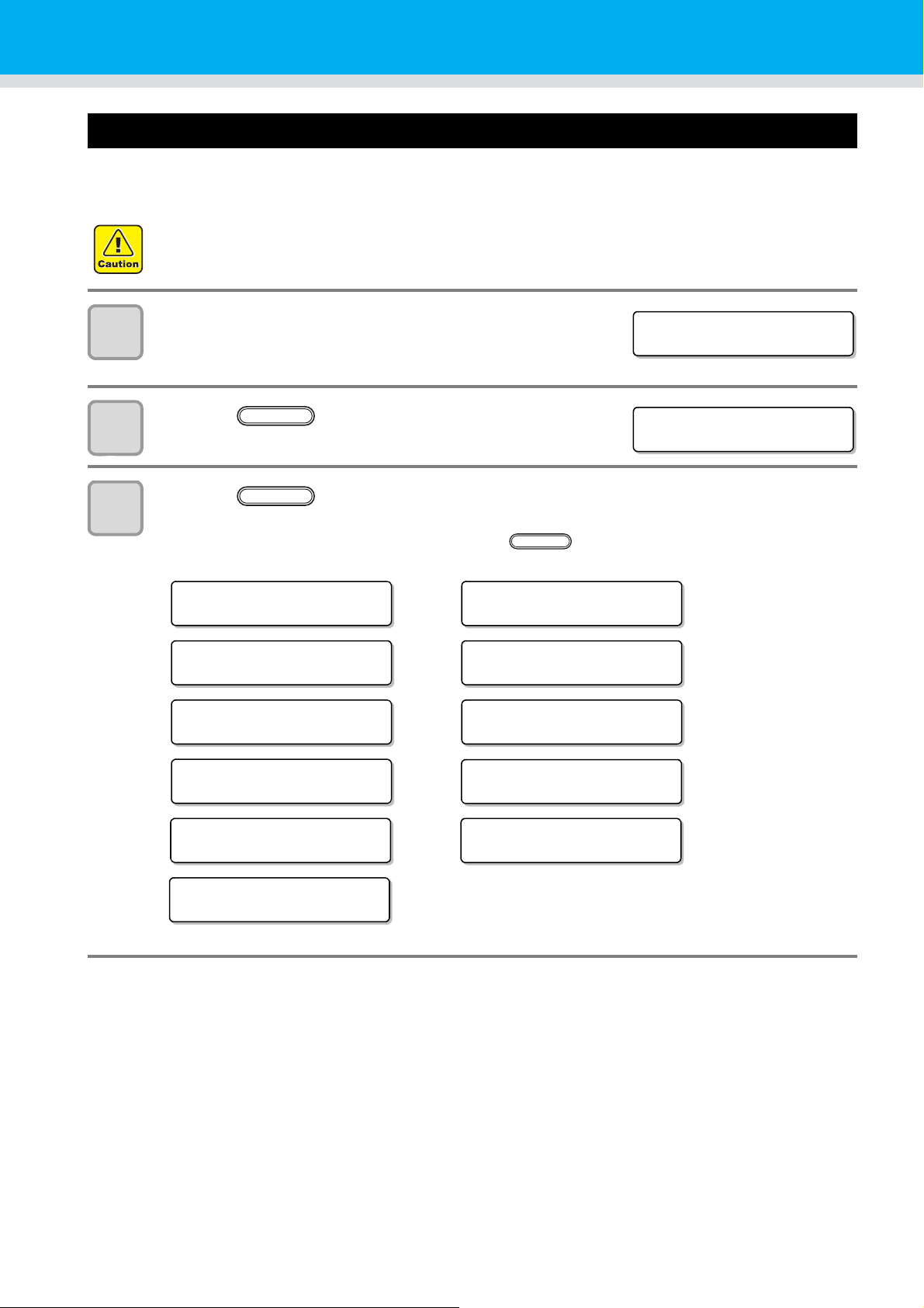
Ink cartridge trouble
<LOCAL>
INK END MCYKW
C
L
<LOCAL> MCYKW
C
L
REMAIN 999999
ENTER
<LOCAL>
INK NEND MCYKW
C
L
<LOCAL>
Co l or o f I NK MCYKW
C
L
<LOCAL>
INK END MCYKW
C
L
<LOCAL>
NO C ART RDGE MCY KW
C
L
<LOCAL>
Exp i rat i on MCYKW
C
L
<LOCAL>
I NK TYPE MCYKW
C
L
<LOCAL>
WR N G I N K I C MCY K W
C
L
<LOCAL>
CARTR I DGE MCYKW
C
L
<LOCAL>
Exp i ra t i on MCYK
CLC
L
WW
<LOCAL>
Exp i rat ion2 MCYK
CLC
L
WW
<LOCAL>
Exp i ra t i on1 MCYK
CLC
L
WW
When an ink cartridge trouble is detected, a warning message appears and printing, cleaning and all other
activities that use ink are deactivated. In this case, replace the ink cartridge in question immediately.
• Do not leave the ink cartridge without replacing for a long time as this will cause the nozzle clogging and
the printer must be repaired by a service person.
Display the truble messages on the LCD.
1
• See P.5-4 "Troubles for which error messages are given on the
LCD".
2
3
Press the key.
Press the key again.
ENTER
ENTER
• The menu will return to the LOCAL mode when there is no trouble.
• If two or more cartridges have a problem, press the key again to display the second cartridge.
• When the problems of all cartridges are displayed, the menu returns to the LOCAL mode automatically.
4-8
Page 85

Shaking the white ink cartridge
Please shake W Cr t rg
PRESS <ENT> KEY
Part A
(Insertion hole of the needle)
Part B
(Gap on the bottom surface)
Cover with paper towel
firmly and shake ink slowly
Repeat this
A part
Shake the white ink cartridge when starting the device or when the following screen is displayed.
(Supported from the firmware ver.4.10)
Pull out the white ink cartridges from the ink
1
station.
Ink cartridge
2
Slowly shake the white ink cartridge more than twenty times right and left.
• To prevent ink from leaking when you shake the cartridge, wear gloves and firmly cover the A part of the
upper surface of the cartridge and the B part of the bottom surface of the cartridge with paper towels.
Then, shake it more than twenty times right and left so that ink flows inside the cartridge.
• If you shake it too strong, the pack inside may be damaged and it may cause ink leakage. Therefore,
perform this carefully.
• If the remaining amount of ink is less, ink in the cartridge cannot be beaten enough. Tilt the cartridge
until it becomes vertical.
4
Maintenance
Return the white ink cartridge to the ink station and press the key.
3
ENTER
4-9
Page 86
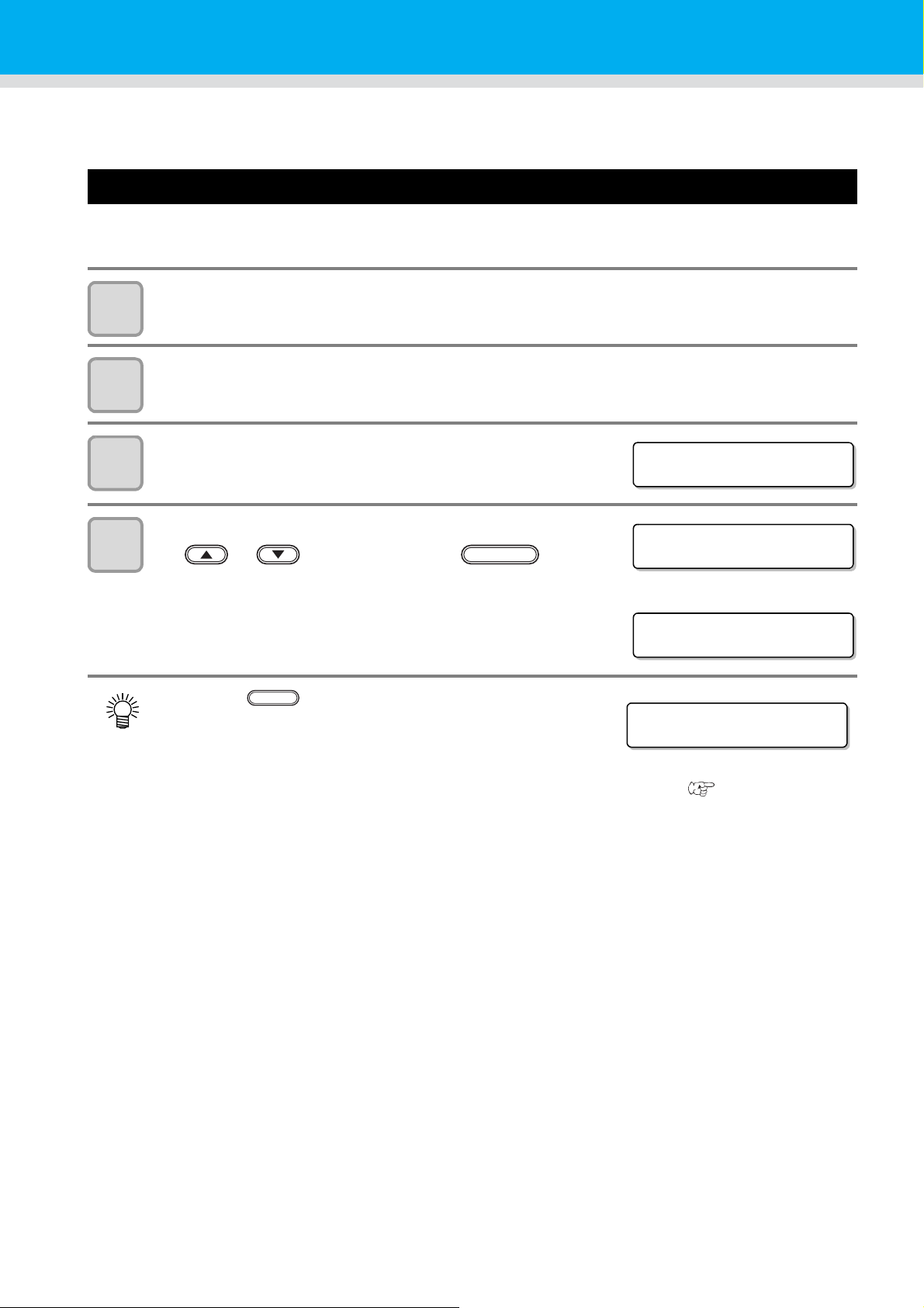
600ml Ink cartridge
<LOCAL>
CART.Sl ot M_______
CASE WEIGHT =325g
<LOCAL>
<LOCAL>
Case We i ght M_______
END
To use the 600ml ink cartridges, register the case weight (this page) and the cartridge weight (next page).
Please prepare your scale (which can weigh up to 1200g in 1g).
Registering the case weight
Firstly register the case weight in the following pr oc ed ur e s .
For the 600ml cartridges, this machine recalculates remaining amount of ink from a registered case weight.
Weigh the case of an empty cartridge on the scale.
1
2
• Do not attach the IC chip and the ink pack when weighing.
Prepare the 600ml cartridge.
• Load the IC chip and the ink pack into an empty cartridge.
Set the 600ml cartridge in the local mode.
3
4
Enter the weight checked at the Step 1 by pressing
the or key, and press the key.
• If other 600ml cartridges are found, an entry screen is
displayed. Repeat the Step 1 to 4.
• When all weights of the 600ml cartridge cases are entered, this
machine returns to the local mode to enable drawing or
cleaning.
• Press the key to cancel the weight entry, but a
screen shown on the right appears in the local mode, and the
600ml cartridge is invalid until the weight is entered.
• If the weight entry is canceled, remove and reinsert the
cartridge to display the weight entry screen again, and enter the weight.
• If the case is replaced, register the case weight again from [MACHINE SET]. ( P.3-30)
ENTER
4-10
Page 87
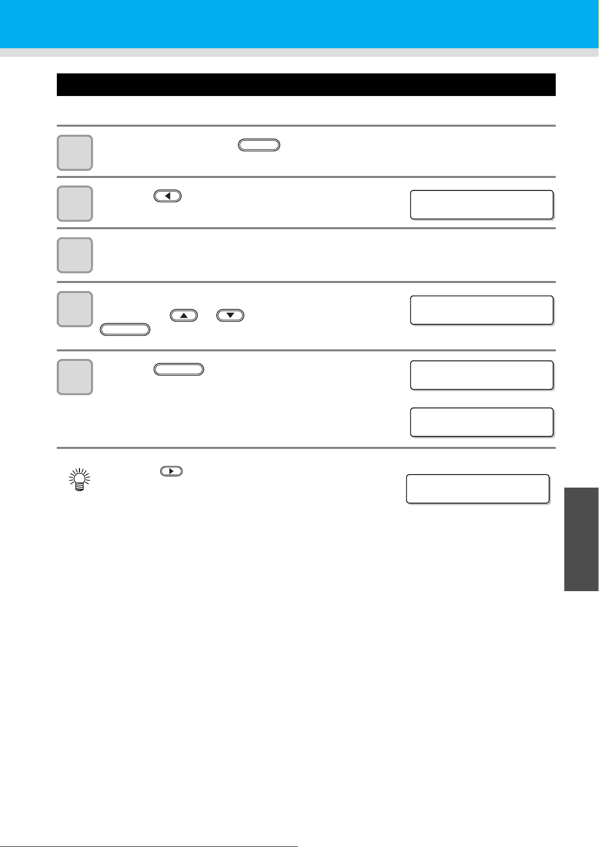
Registering the cartridge weight
InkLevelSet M_______
Exec < > Cancel
InkLevelSet M_______
WE I GH T = 7 8 9 g
ENTER
InkLevelSet M_______
789g OK? :ent
<LOCAL>
<LOCAL>
Ink Weight M_______
After filling ink into the 600ml cartridge, register the cartridge weight.
600ml Ink cartridge
1
2
3
4
5
After filling ink, press the key several times.
Press the key.
• An entry screen of the weight is displayed.
Remove the target cartridge, and weigh it on the scale.
Set the 600ml cartridge, enter the weight by
pressing the or key, and press the
key.
Press the key again.
• If other 600ml cartridges are found, the entry screen is
displayed. Repeat the Step 2 to 5.
• When all weights of the 600ml cartridges are entered, this
machine returns to the local mode to enable drawing or
cleaning.
ENTER
END
• Press the key to cancel the weight entry, but a screen
shown on the right appears in the local mode, and the
canceled cartridge is invalid until the weight is entered.
• If the weight entry is canceled, remove and reinsert the
cartridge to display the weight entry screen again, and enter the weight.
4
Maintenance
4-11
Page 88
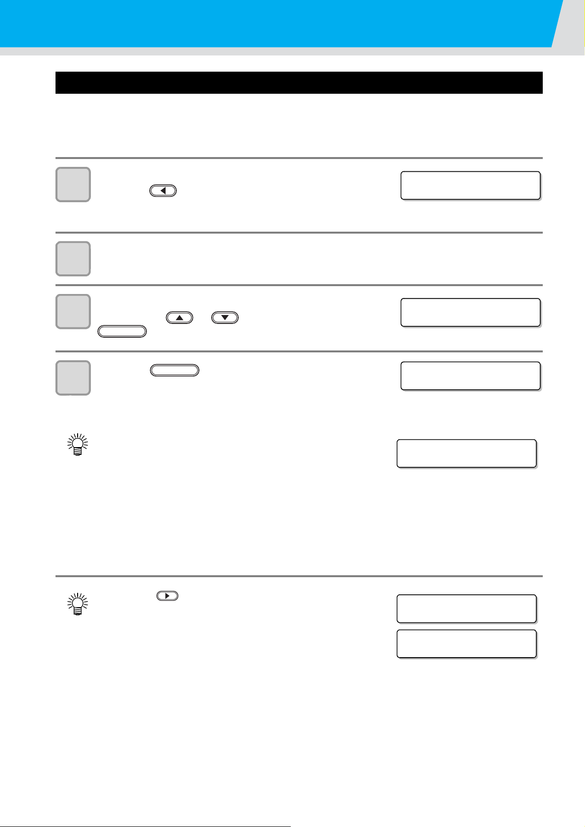
600ml Ink cartridge
InkLevelSet M_______
Exec < > Cancel
InkLevelSet M_______
WE I GH T = 4 5 0 g
ENTER
InkLevelSet M_______
450g OK? :ent
<LOCAL>
INK NEAR ENDMC______
<LOCAL>
INK LVL LOW M_______
<LOCAL>
INK LVL END M_______
Registering the cartridge weight (After LVL LOW / LVL END)
The 600ml cartridge becomes level low when ink remains 60ml or less, and level end when ink remains 25ml or
less.
In this case, register the cartridge weight on the entry screen that is displayed.
The level low or level end cartridge cannot be used until the weight is entered.
When a screen shown on the right appears,
1
press the key.
• This screen appears when returning to the local after LVL LOW
or LVL END is detected.
Remove the target cartridge, and weigh it on the scale.
2
Set the 600ml cartridge, enter the weight by
3
pressing the or key, and press the
key.
4
Press the key again.
• If other 600ml cartridges are found, an entry screen is
displayed. Repeat the Step 1 to 4.
• After LVL LOW and after you enter the cartridge weight, if ink
remains 31ml and more, you can print as usual. Then, when
ink is used and ink remains 30ml and less, the status
becomes INK NEAR END.
• LAfter LVL LOW and after you enter the cartridge weight, if ink remains 30ml and less, the status
becomes INK NEAR END.
• If the status becomes INK NEAR END, you can draw, however, you cannot perform cleaning nor ink
filling of the relevant head.
• LAfter LVL LOW and after you enter the cartridge weight, if ink remains 26ml or more, the status
becomes INK NEAR END.
• After LVL LOW and after you enter the cartridge weight, if ink remains 25ml and less, the status of LVL
END is not eliminated. Set a new ink cartridge.
• Press the key to cancel the weight entry, but a screen
shown on the right appears in the local mode, and the
canceled cartridge is invalid until the weight is entered.
ENTER
• If the weight entry is canceled, remove and reinsert the
• When total entered weight of ink exceeds 1000ml, “Save Failure” error occurs again and entry becomes
4-12
cartridge to display the weight entry screen again, and enter the weight.
invalid.
Page 89
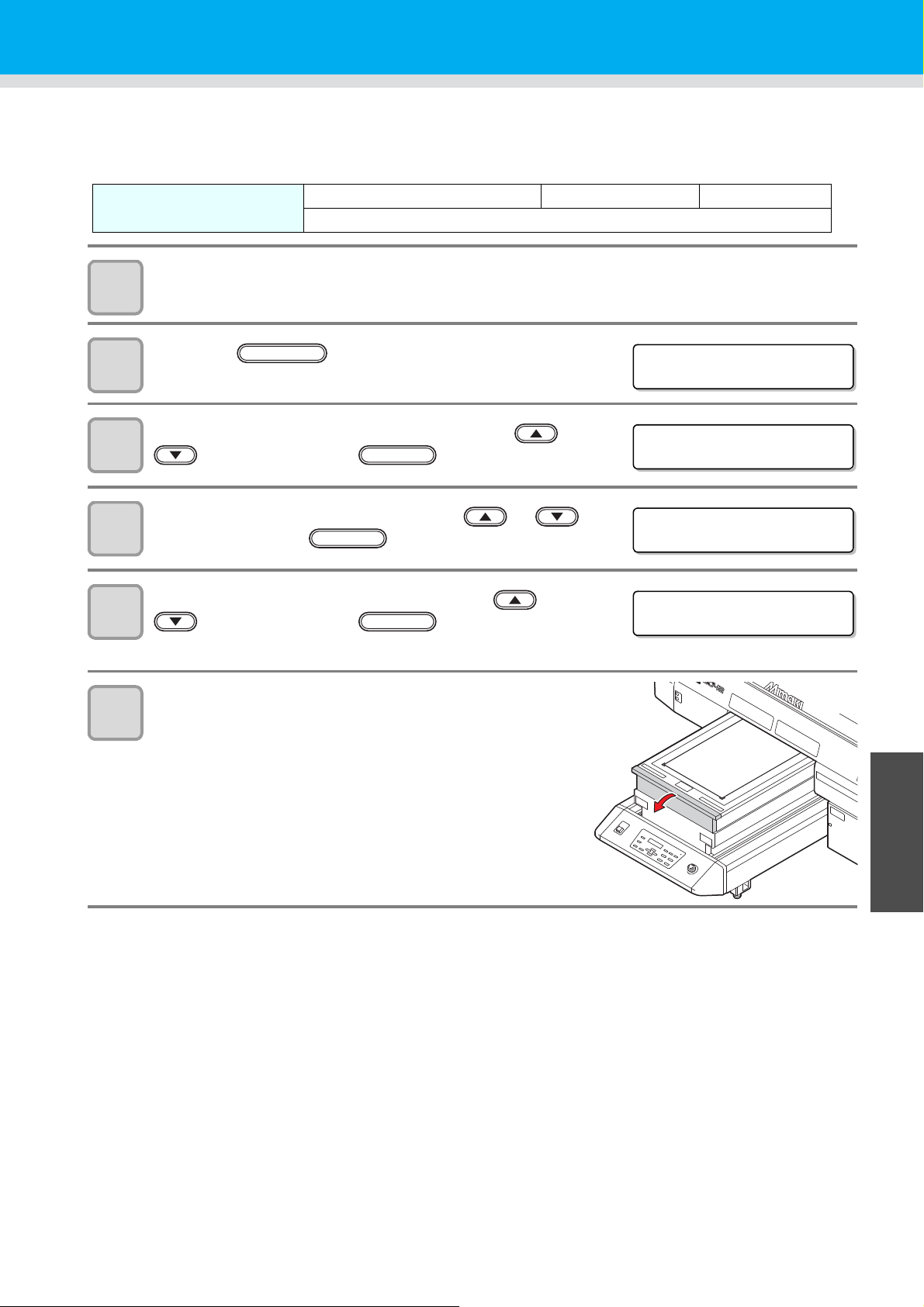
Avoiding dripping of ink droplet at printing
<LOCAL>
FUNCTION
FUNC T I ON
MA I N TE NANC E < EN T >
ENTER
MA I N TE NANC E
STAT ION <en t>
ENTER
STAT ION
MEN T : HE AD MEN T
Ink droplets from the mist at drawing may arise on the bottom of the carria ge. As the ink droplets may drip and
stain the media or cause blur or dot missing, clean the bottom of the carriage periodically.
1
2
3
4
5
Tools
Turn the power on.
• After initializing, <LOCAL> is displayed.
Press the key in the local mode.
Select the [MAINTENANCE] by pressing the or
key, and press the key.
Select the [STATION] by pressing the or
key, and press the key.
Select the [HEAD MENT] by pressing the or
key, and press the key.
• The carriage automatically moves to the center of the front end.
• UJ Cleaning swab (SPC-0386) • Gloves • Goggles
• F-200 / LF-200 Washing Liquid (SPC-0568)
ENTER
6
Open the table front cover.
4
Maintenance
4-13
Page 90

7
Bottom of the carriage
Light pointer
LED-UV irradiation
outlet (glass)
STAT ION
COMPL E TE D : e n t
ENTER
8
Avoiding dripping of ink droplet at printing
Dip the cleaning swab into the cleaning solution,
and clean the side surface of the head.
• Do not wipe the nozzle face of the head. It may cause nozzle
clogging.
• To buy special cleaning swabs, contact a distributor in your
district or our office.
• Be careful not to put the cleaning solution on the light pointer.
Dip the TechnoWipe (attached) into alcohol, and
clean the LED-UV irratiation outlet.
9
After cleaning, close the table front cover, and press
the key.
• Initializing starts.
4-14
Page 91

When the waste ink is full
<LOCAL>
FUNCTION
FUNC T I ON
MA I N TE NANC E < EN T >
MA I N TE NANC E
STAT ION <en t>
ENTER
STAT ION
MENT :WASTE TANK
ENTER
Waste ink used for head cleaning gathers in the waste ink tank and the wiper bottle.
Periodically check the waste ink tank and the wiper bottle and when they are full, dispose of the ink.
If warning message such as “!WS INKTANK CHK” or “WIPER BOTTLE” appears, check the waste ink tank and
the wiper bottle in the same way.
• If you need a spare waste ink tank, contact a distributor in your district or our office.
• When ink is discharging such as for head cleaning, conduct the operation after the discharging is
completed.
• Handle the waste ink tank with care not to spill the waste ink.
• Dispose of the waste ink when it has gathered about half of the waste ink tank.
• Check the waste ink level in the waste ink tank frequently.Continuing to use the product without
disposing of the waste ink may result in waste ink overflowing from the waste ink tank.
Tools
• Gloves • Goggles
Disposing of the ink in the waste ink tank
Turn the power on.
1
• After initializing, <LOCAL> is displayed.
Press the key in the local mode.
2
Select the [MAINTENANCE] by pressing the or
3
4
5
key, and press the key.
Select the [STATION] by pressing the or
key, and press the key.
Select the [MENT:WASTE TANK] by pressing the
or key, and press the key.
ENTER
4
Maintenance
4-15
Page 92

6
STAT ION
COMPL E TE D : e n t
7
Open the waste ink box cover.
• By pressing the cover lightly, the cover opens to the front.
Remove the waste ink tank.
• Lifting the tank slightly up, pull it to the front.
• Put a cap on the waste ink tank removed.
8
9
10
Set the new waste ink tank, and close the cover.
(1)Set the waste ink tank in the reverse order of removing.
(2)Close the waste ink box cover.
• Dispose of the waste ink pursuant to the
regulations of your district.
Press the key.
Press the key to finish.
ENTER
END
4-16
Page 93
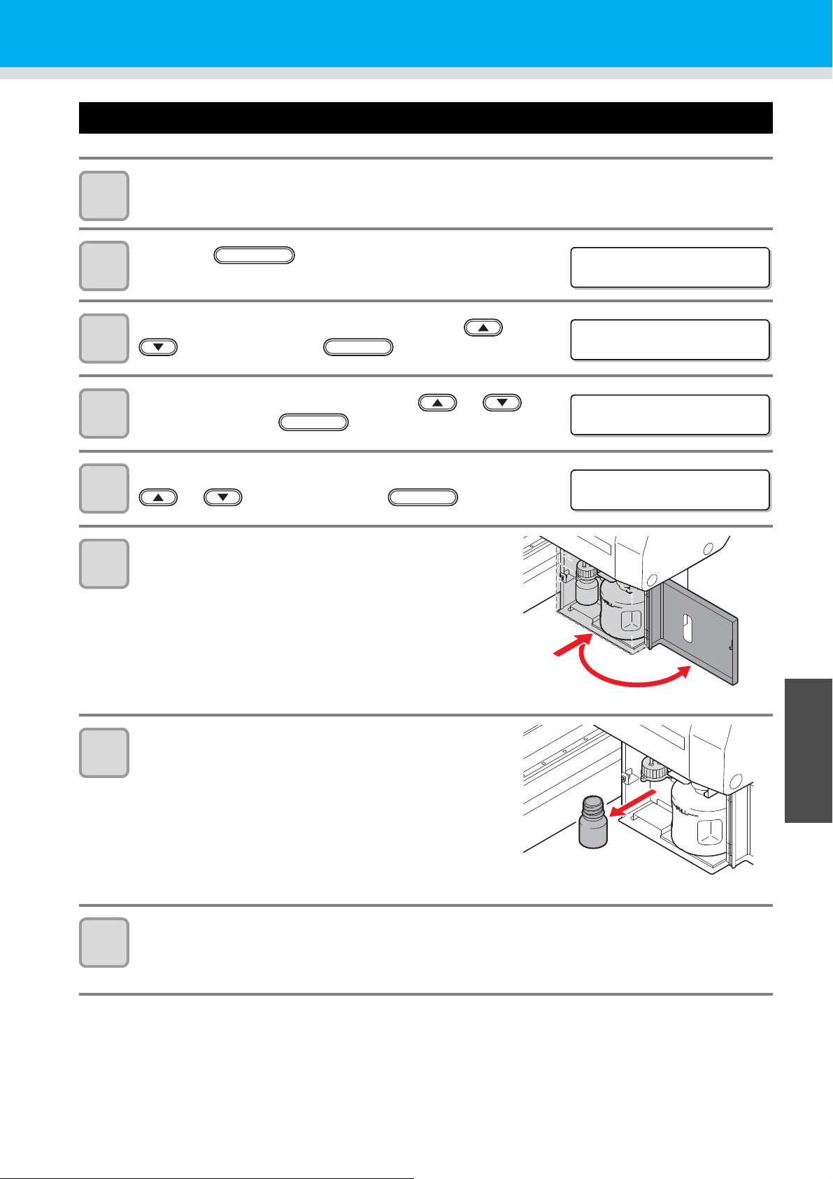
Disposing of the waste ink in the wiper bottle
<LOCAL>
FUNCTION
FUNC T I ON
MA I N TE NANC E < EN T >
MA I N TE NANC E
STAT ION <en t>
ENTER
STAT ION
MEN T : W I PE R B OT T L E
ENTER
Turn the power on.
1
• After initializing, <LOCAL> is displayed.
Press the key in the local mode.
2
Select the [MAINTENANCE] by pressing the or
3
4
key, and press the key.
Select the [STATION] by pressing the or
key, and press the key.
ENTER
When the waste ink is full
5
6
7
Select the [MENT:WIPER BOTTLE] by pressing the
or key, and press the key.
Open the waste ink box cover.
• By pressing the cover lightly, the cover opens to the front.
Take the wiper bottle out, and dispose of the
waste ink.
• Turn the bottle holding the cover, take out the bottle, and
then dispose of the ink in the bottle.
• Dispose of the waste ink pursuant to the regulations of
your district.
4
Maintenance
Set the wiper bottle.
8
(1)Turn the bottle holding the cover, and close the cover.
(2)Close the waste ink box cover.
4-17
Page 94

When the waste ink is full
STAT ION
COMPL E TE D : e n t
9
10
Press the key.
Press the key to finish.
ENTER
END
4-18
Page 95
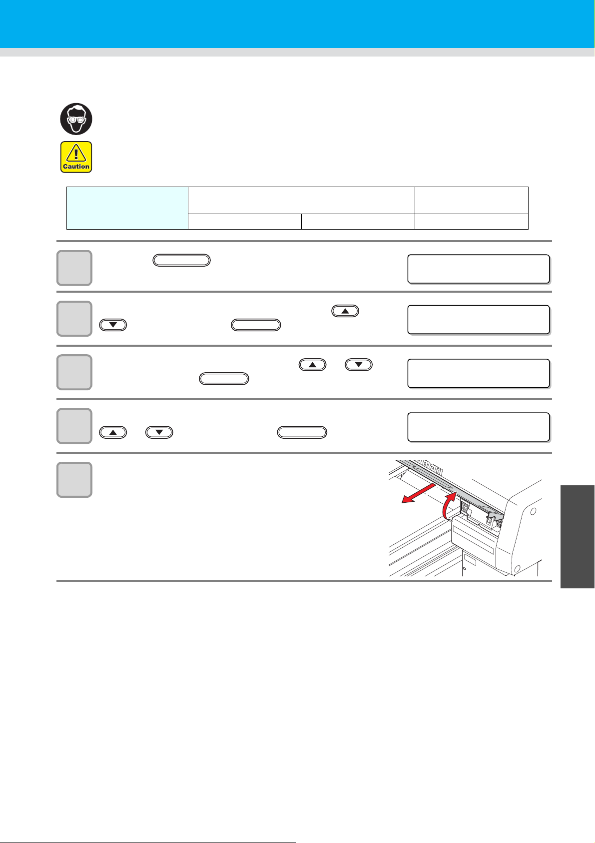
Replacing the Filter
<LOCAL>
FUNCTION
FUNC T I ON
MA I N TE NANC E < EN T >
MA I N TE NANC E
STAT ION <en t>
ENTER
STAT ION
MEN T : CH ECK F I L T ER
ENTER
To use this machine for a long time, clean the filter periodically (about once a week).
• Put on supplied goggles and gloves. Ink may splash into the eye.
• When a screw is dropped in replacing of the filter, contact a distributor in your district or our office.
• LED UV unit filter (SPC-0657) • Mist adsorption filter
Tools
• Gloves • Paper towel • Goggles
Press the key in the local mode.
1
Select the [MAINTENANCE] by pressing the or
2
key, and press the key.
ENTER
(SPC-0656)
3
4
5
Select the [STATION] by pressing the or
key, and press the key.
Select the [MENT:CHECK FILTER] by pressing the
or key, and press the key.
Remove the front cover.
(1)Push the both ends of the front cover.
(2)Pull the cover to the front while opening upward.
4
Maintenance
4-19
Page 96
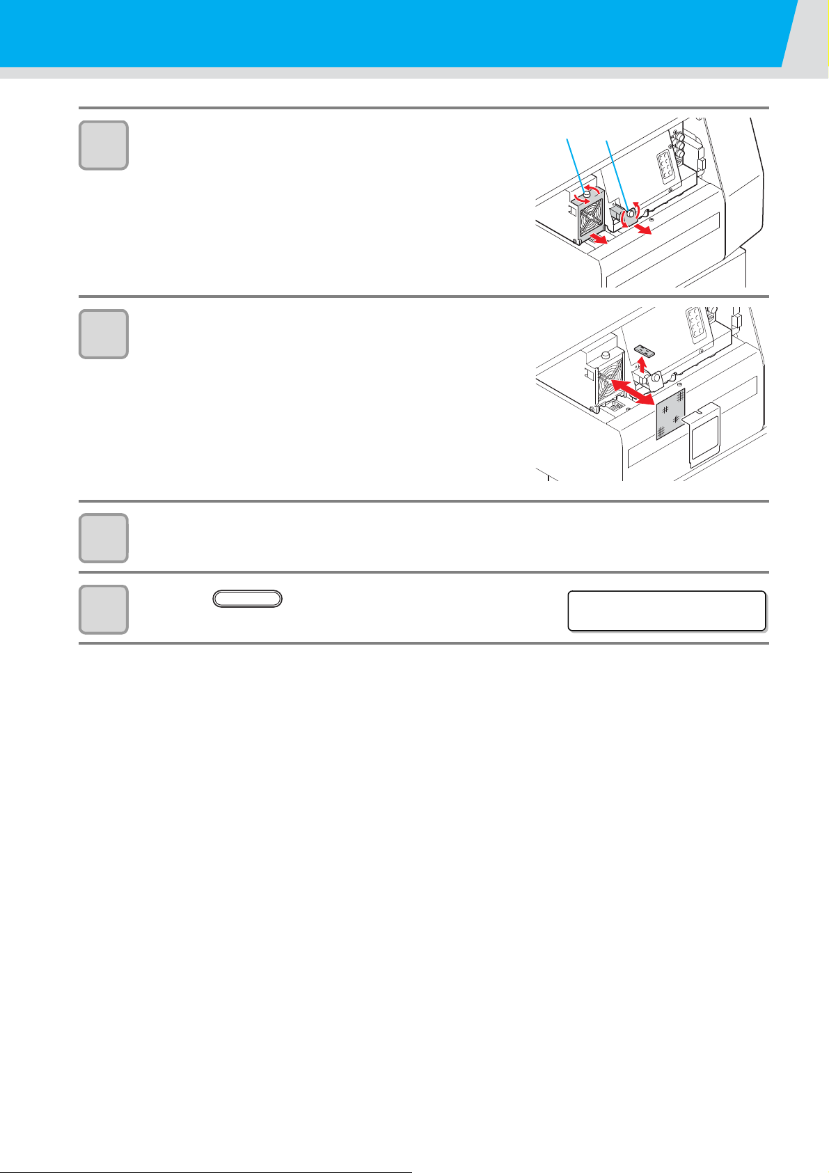
6
(2) (1)
STAT ION
COMPL E TE D : e n t
ENTER
7
Replacing the Filter
Remove the filter retainer (2 places).
(1)Turn and pull the right white knob.
(2)Turn the left white knob and pull the frame of the filter.
Replace the filters (2 places).
• Replace two filters.
8
9
Attach the covers.
• Attach in reverse order of step 5, 6.
Press the key.
• Initializing starts.
4-20
Page 97

Washing the Nozzle
<LOCAL>
FUNCTION
FUNC T I ON
MA I N TE NANC E < EN T >
MA I N TE NANC E
STAT ION <en t>
ENTER
STAT ION
MEN T : NO ZZ L E WAS H
ENTER
STAT ION
HEAD [123]
ENTER
To prevent nozzle clogging, execute nozzle washing at the end of the daily work.
• Put on supplied goggles and gloves.
1
2
3
4
5
Tools
Press the key in the local mode.
Select the [MAINTENANCE] by pressing the or
key, and press the key.
Select the [STATION] by pressing the or
key, and press the key.
Select the [MENT:NOZZLE WASH] by pressing the
or key, and press the key.
• The carriage moves to the center, and the Y-bar moves to the
front.
Set all the heads to execute washing, and press the
key.
(1)Select the head with the key.
(2)Select executing (displays the head No.) or not executing (displays “_”) of the nozzle washing with
the key.
• UJ Cleaning swab (SPC-0386) • Gloves • Goggles
• F-200 / LF-200 Washing Liquid (SPC-0568)
ENTER
Remove the front cover.
6
• The wiper moves to the front.
4
(1)Push the both ends of the front cover.
(2)Pull the cover to the front while opening upward.
Maintenance
4-21
Page 98
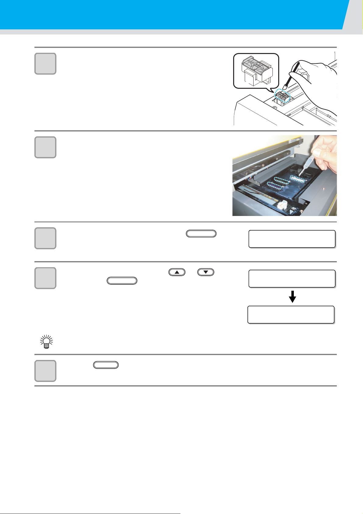
7
Front
Back
Fill the liquid.
COMPL E TE D : e n t
STAT ION
LEAVING : 1mi n
CLEAN ING ACTI VE
***-----------------
ENTER
END
8
Washing the Nozzle
Dip washing liquid into the cleaning swab, and wipe
dirt of the wiper nozzle.
• Wipe the places shown in the right.
Put washing liquid into the dropper , and drop on the
caps to fill them.
• Fill the washing liquid into the three caps.
9
10
11
Replace the front cover, and press the
key.
• Capping is performed.
Set leaving time by pressing the or key,
and press the key.
• Usually set 10 min.
(Set value: 1 to 99 min)
• After the leaving time, cleaning is performed.
• Adjust the leaving time depending on frequency of use or dirt of the nozzle.
Press the key to finish.
ENTER
4-22
Page 99
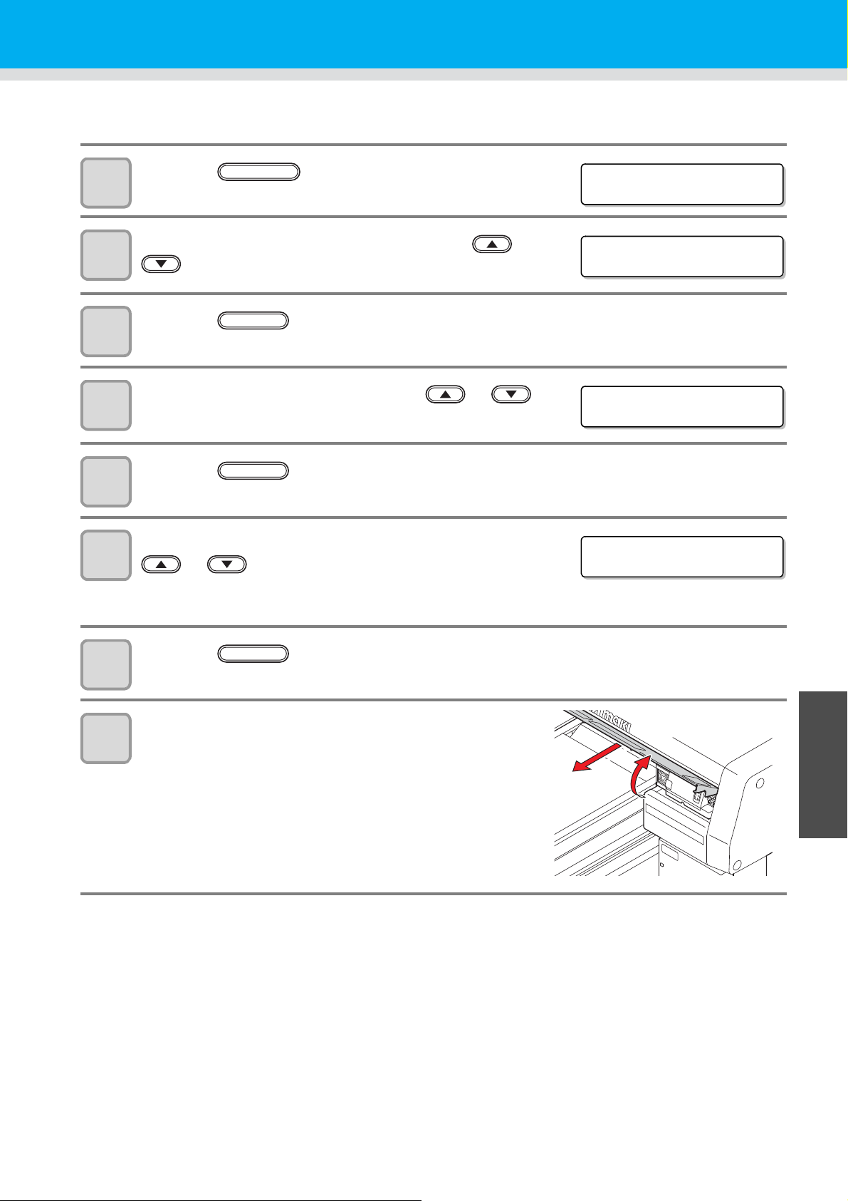
Wash the ink discharge passage
<LOCAL>
FUNCTION
FUNC T I ON
MA I N TE NANC E < EN T >
MA I N TE NANC E
STAT ION <en t>
ENTER
STAT ION
MEN T : D I SWAY WAS H
Wash the ink discharge passage regularly to prevent the head nozzles from clogging due to ink coagulation
inside the passage.
Press the key in the local mode.
1
Select the [MAINTENANCE] by pressing the or
2
key.
3
4
5
6
7
8
Press the key.
Select the [STATION] by pressing the or
key.
Press the key.
Select the [MENT:DISWAY WASH] by pressing the
or key.
• The carriage moves to the center, and the Y-bar moves to the
front.
Press the key.
Remove the front cover.
(1)Push the both ends of the front cover.
(2)Pull the cover to the front while opening upward.
ENTER
ENTER
4
Maintenance
4-23
Page 100

9
Fill the liquid.
COMPL E TE D : e n t
ENTER
10
Wash the ink discharge passage
Put washing liquid into the dropper, and drop on the
caps to fill them.
• Fill the washing liquid into the three caps.
Replace the front cover, and press the
key.
• Capping is performed.
4-24
 Loading...