

Page 1
Temp-O-Matic Oil Furnaces
THB High Boy
TLB Low Boy
Furnace Manual
KEEP THESE INSTRUCTIONS
WITH FURNACE FOR FUTURE
REFERENCE.
C US
Hazards that will cause severe personal injury,
death or substantial property damage.
Hazards that can cause severe personal injury,
death or substantial property damage.
INSTALLER – Read all instructions before
installing. Read page 2 first. Follow all instructions
in proper order to prevent personal injury or death.
• Consider ducting, fuel supply, venting and
installation when determining furnace location.
• Any claims for damage or shortage in shipment
must be filed immediately against the transportation
company by the consignee.
Do not store or use gasoline or other flammable
liquids or vapors near this furnace or any other
appliance.
Ventilate house while operating furnace for the first
time. Odors may be emitted for a brief period.
Do not alter this furnace in any way. The
manufacturer will not be liable for any damage
resulting from changes made in the field to the
furnace or its components or from improper
installation. Failure to comply could result in severe
personal injury, death or substantial property
damage.
Printed on 100% recycled paper 670-000-005/1010
Hazard definitions
Contents Page
Read this first!............................................................................ 2
1. Prepare furnace location............................................................ 3
2. Prepare furnace and place in position ....................................... 6
3. Connect supply and return ducts...............................................8
4. Venting..................................................................................... 11
5. Connect fuel oil piping ............................................................. 12
6. Wire furnace and burner..........................................................12
7. Start-up....................................................................................16
8. Checkout procedure ................................................................ 16
9. Troubleshooting....................................................................... 18
10. Service and maintenance ........................................................ 19
11. Components and replacement parts........................................ 23
12. Dimensions and ratings ........................................................... 29
13. Owner’s information .................................................................34
Hazards that will or can cause minor personal
injury or property damage.
Special instructions on installation, operation or
maintenance that are important but not related to
personal injury or property damage.
USER – Please read the following. Failure to
comply could result in severe personal injury, death
or substantial property damage.
• This manual is for use only by your qualified
heating installer / service technician.
• Please see the Owner’s information only, on back
page of this manual.
• Have the furnace serviced by a qualified service
technician, at least annually.
This manual must only be used by a qualified
heating installer / service technician. Furnace and
burner must be installed and serviced only by a
qualified heating installer / service technician.
Failure to comply could result in severe personal
injury, death or substantial property damage.
When calling or writing about the furnace – Please
have furnace model number and serial number from
the rating label. You may list the serial number and
model number in the space provided on the
“Installation and service certificate” found on
page 17.
Page 2
READ THIS FIRST!
Service and maintenance –
1. To avoid electric shock, disconnect electrical supply before
performing maintenance.
2. To avoid severe burns, allow furnace to cool before performing
maintenance.
3. Perform service and maintenance as described in this manual
and the burner manual.
4. Do not attempt to make adjustments to the blower or motor while
the furnace is in operation. Disconnect power to the furnace and
be sure all parts have stopped moving before attempting
adjustments or maintenance.
5. The burner must be set up and adjusted using combustion test
instruments. Visual examination of the flame alone cannot
determine combustion performance.
Operation -
6. Do not use the furnace as a construction heater.
7. Do not operate any furnace if the heat exchanger is damaged,
corroded or pitted. Toxic flue products could enter the air
stream.
8. Do not jumper, attempt to by-pass or override any limit control.
9. Do not block flow of combustion or ventilation air to furnace. Do
not block or obstruct the air openings in the furnace casing.
10. Do not store or use combustible materials, gasoline, or other
flammable liquids or vapors in the furnace area.
11. Do not operate the furnace if the furnace area will be exposed to
air contaminants as described on page 5.
12. Should overheating occur, do not turn off or disconnect electrical
supply to furnace. Instead, shut off the oil supply at a location
external to the appliance, if possible.
13. Do not use this furnace if any part has been under water.
Immediately call a qualified service technician to inspect the
furnace and to replace any part to the furnace, control system or
burner that has been under water.
14. Do not operate furnace if temperature rise through heat
exchanger exceeds 85
Installation –
1. Be sure to level the furnace, using a spirit level on the front and
one side. If the furnace is not level, oil can drip into the
combustion chamber after burner cycling, causing fouling of the
heat exchanger and the burner head.
2. Make sure the legs are in contact with the floor to distribute the
load and prevent the possibility of undue noise or vibration.
.
Failure to adhere to the guidelines below can result in severe personal injury, death or substantial property damage.
o
F.
Apply the following suggestions to prevent unsatisfactory operation of the furnace.
15. Inspect, clean and replace (if necessary) return air filter
regularly.
16. Do not obstruct return air grills or supply air outlets.
17. Supply only #2 fuel oil to the burner. Never attempt to use
gasoline, a mixture of gasoline and oil, waste fuel, refuse or any
other substance in the burner of furnace.
Installation -
18. Do not block flow of combustion or ventilation air to furnace. Do
not block or obstruct the air openings in the furnace casing.
19. Connect furnace only to a functional vent system in good
condition. Place the furnace to allow proper venting, with the
shortest possible venting and minimum number or elbows.
20. Always connect and seal a return air duct to the furnace unless
the furnace is located in a large space, such as an unpartitioned
basement, Route the return air duct to an adjacent room if no
return air manifold is used.
21. Install furnace maintaining minimum clearances for service and
separation from combustible surfaces described in this manual.
If furnace is installed on a combustible floor, you must use the
combustible floor base or provide the minimum clearance from
the furnace to the floor as given in this manual.
22. Install, start-up, service and maintain burner per instructions in
this manual and the burner manual.
23. Verify burner is properly inserted through the combustion
chamber opening.
24. Furnace must be installed so that burner and control system
components are protected from dripping, spraying water or rain
during operation or service.
25. If installing an air conditioning evaporator coil, install the coil
downstream of, or in parallel with, the furnace to prevent
condensation on the furnace heat exchanger. If the coil is in
parallel, provide means to prevent flow of chilled air into the
furnace, including an interlock to prevent simultaneous operation
of heating and air conditioning.
3. Avoid locating return grills in rooms that may contain undesirable
odors.
4. Never locate a return air grill closer than approximately 20 feet
from the furnace.
5. Locate the furnace near the center of the supply and return duct
systems.
6. Always check the size of the ducts on a replacement installation,
particularly if adding air conditioning.
2 670-000-005/1010
Page 3
THB & TLB Oil Furnaces – Furnace Manual
1 Prepare furnace location
Pre-installation checklist
Verify code compliance
Local, state, provincial, and national codes, laws, regulations
and ordinances
NFPA-31, Installation of Oil-Burning Equipment
National Electrical Code
All local codes and/or regulations take precedence over the
instructions in this manual and should be followed accordingly.
THB & TLB furnaces, their burners and controls met
safe lighting and other performance criteria when
furnace underwent tests specified in Underwriters
Laboratories Standard UL727.
Check location and furnace specifications
Furnace heating capacity
Space is large enough to provide required clearances
Verify the installation will meet the requirements of this manual:
Clearances (page 3)
Combustion/ventilation air openings (page 4)
Supply air duct (page 8)
Return air duct (page 8)
Vent system (page 11)
Fuel oil piping (page 12 plus burner manual)
Electrical connection (page 12)
Clearances
Minimum clearance to combustible materials
1. Install the furnac e, ductwork and vent such that no combustible
surface is closer than listed in Table 1.
Table 1 Minimum clearances
Minimum clearances from furnace, ductwork and vent
Flue pipe clearances must take precedence over
jacket clearances (listed below).
Service accessibility clearances
1. Provide no less than the minimum clearances given in Table 1 to
ensure the furnace can be properly operated, serviced and
maintained.
Always apply whichever clearance is LARGER – combustible
construction or service accessibility.
Flooring and foundation
Flooring
THB & TLB furnaces are approved for installation on combustible
flooring, but must never be installed on carpeting.
Do not install furnace on carpeting even if foundation
is used. Fire can result, causing severe personal
injury, death or substantial property damage.
Foundation
1. Provide a solid brick or minimum 2-inch concrete foundation pad
if any of the following is true:
• The floor can become flooded.
• The furnace mounting area is not level.
Residential garage installations
Take the following special precautions when installing the furnace in
a residential garage. Il the furnace is located in a residential garage:
• Mount the furnace a minimum of 18 inches above the floor
of the garage.
• Locate or protect the furnace so it cannot be damaged by a
moving vehicle.
Servic e acces s ibilit y clearance s are recom m ended
minim um dim ensions to allow ac c es s to furn ace
components (motor, blower, filters, etc.).
Top of plenum t o ce iling 1" 1"
Above warm air duct within 6 fee t of furna ce 1" 1"
Front of furn ace 1 8" (alc ov e) 18" 18" (alc ov e) 18"
Flue pipe (or bar om et ric d. c.) to any surfac e 9" (note 1) 18" 9" (not e 1) 18"
Rea r of furnace 0" 0"
Side of furnace 0" 0"
Warm air plenum t o wall 1" 1"
Combustible floor 0" 0"
Note 1 : Single wall metal vent (or barometric draft control) can be no closer than 9 inches to any combustible surfac e. Apply requirement s of NFPA 31
an d local codes to red uce c l earance using dou bl e-wall vent pi pe and/or pro tectiv e i nsulati on be twee n the flue pi pe or barometric draft control and
combustible surfa ces. Minimum clearance when u sing Type L double-wall vent pipe is 6”.
670-000-005/1010 3
TH B Furnaces TL B Furnac e s
To combust i ble
construction
For serv ice
accessibility
To combustible
construction
For serv ice
accessibility
Page 4

THB & TLB Oil Furnaces – Furnace Manual
1 Prepare furnace location (continued)
Air for combustion and ventilation
Adequate combustion and ventilation air ensures
proper combustion and reduces risk of severe
personal injury or death from possible flue gas
leakage and carbon monoxide emissions.
Do not install exhaust fan in furnace room.
Consider building construction
Older buildings with single-pane windows, minimal weatherstripping and no vapor barrier often provide enough natural
infiltration and ventilation without dedicated openings.
New construction or remodeled buildings are most often built
tighter. Windows and doors are weather-stripped, vapor barriers
are used and openings in walls are caulked. As a result, such
tight construction is unlikely to allow proper natural air infiltration
and ventilation.
For buildings with tight construction, provide openings directly to
outside or to a ventilated crawl space or attic. Size the openings
to the same specifications as for the furnace location per the
following paragraphs.
Follow state, provincial or local codes when sizing adequate
combustion and ventilation air openings. In absence of codes,
use the following guidelines when furnace is in a confined room
(defined by NFPA 31 as less than 7,200 cubic feet per 1 GPH
input of all appliances in area. A room 8 ft. high x 30.0 ft. x 30.0 ft.
is 7200 cu. ft.).
Provide two permanent openings:
Opening locations
One within 12 inches of ceiling, one within 12 inches of floor.
Minimum height or width dimension of each rectangular opening
should be at least 3 inches.
When inside air is used:
Each opening must freely connect with areas having adequate
infiltration from outside. Each opening should be at least 140 sq.
in. per 1 GPH input (1 sq. in. per 1000 BTU input) of all fuelburning appliances plus requirements for any equipment that can
pull air from room (including clothes dryer and fireplace).
When outside air is used
Connect each opening directly, by way of ducts to the outdoors,
or to crawl or attic space that freely connects with outdoors. Size
per below:
• Throug h outside wall or vertical ducts – at least 35 sq. in. per
1 GPH input (1sq. in. per 4,000 BTU input) of all fuel burning
appliances plus requirements for any equipment that can pull
air from room (including clothes dryer and fireplace).
• Through horizontal ducts – at least 70 sq. in. per 1 GPH
furnace input (1 sq. in. per 2,000 BTU input) of all fuelburning appliances plus requirements for any equipment that
can pull air from room (including clothes dryer and fireplace).
• Where ducts are used, they should have the same crosssectional area as free area of openings to which they
connect. Compensate for louver, grille or screen blockage
when calculating free air openings. Refer to their
manufacturer’s instructions for details. If unknown, use:
• Wood louvers, which provide 20-25 % free air.
• Metal louvers or grilles, which provide 60-75 % free air.
Lock louvers in open position or interlock with equipment to
prove open before furnace operation.
Basement installations
When the furnace is located in an unconfined space, such as an
unpartitioned basement, adequate air should normally be
available without additional opening. An unconfined space is
defined as one having no less than 50 cubic feet room volume
per 1,000 BTU input of all appliances in the space.
If the house is of tight construction, provide air openings to the
basement directly from outside or from a ventilated attic. Size the
openings as described above under “When outside air is used”.
Closet installations – special NOTICE
Openings in closet doors
Provide TWO openings – one within 6 inches of top of closet
door, the other within 6 inches of the bottom of closet door.
EACH opening must be at least 24 inches wide by 12 inches
high.
Advise homeowner that the openings to the
closet must never be obstructed or blocked in any
way. Failure to provide adequate air for
combustion and ventilation could result in severe
personal injury, death or substantial property
damage.
4 670-000-005/1010
Page 5
THB & TLB Oil Furnaces – Furnace Manual
1 Prepare furnace location (continued)
Air contamination
Please review the following information on potential combustion air
contamination problems.
See Table 2 for products and areas which may cause contaminated
combustion air.
To prevent potential of severe personal injury or
death, check for products or areas listed below
before installing furnace. If any of these
contaminants are found:
• Remove contaminants permanently.
-OR-
• Isolate furnace and provide outside combustion air. See
national, provincial or local codes for further information.
Table 2 Corrosive contaminants and likely locations
Products to avoid
Spray cans containing chloro/fluorocarbons
Permanent wave solutions
Chlorinated waxes/cleaners
Chlorine-based swimming pool chemicals
Calcium chloride used for thawing
Sodium chloride used for water softening
Refrigerant leaks
Paint varnish remov ers
Hydrochloric acid/muriatic acid
Cements and glues
Antistatic fabric softeners used in clothes dryers
Chlorine-type bleaches, detergents, a nd cleaning solvents found in
household laundry rooms
Adhesives used to fasten building products and othe r similar
products
Areas likely to have contaminants
Dry cleaning/laundry areas and establishments
Swimming pools
Metal fabrication plants
Beauty shops
Refrigeration repair shops
Photo processing plants
Auto body shops
Plastic manufacturing plants
Furniture refinishing areas and establishments
New building construction
Remodeling areas
Garages with workshops
670-000-005/1010 5
Page 6
THB & TLB Oil Furnaces – Furnace Manual
2 Prepare furnace and place in position
Inspect & prepare furnace
Remove furnace from carton
Remove the furnace from its shipping carton and inspect thoroughly.
Remove access panels to inspect the furnace interior.
Immediately file a claim with the transportation
company if you discover concealed damage.
Do not install or attempt to operate the furnace if the
heat exchanger, burner or controls have been
damaged. Immediately contact your furnace
supplier. Operating a damaged furnace could result
in severe personal injury, death or substantial
property damage.
Prepare furnace (THB models)
THB furnaces require cutting the return air opening into one side of
the furnace. Carefully cut the opening on the correct side of the
furnace, using the four knockouts on the side as guide.
Prepare burner
Remove the burner from its shipping carton and inspect thoroughly.
Read the burner manual and follow instructions for preparing and
installing the burner.
Install the correct nozzle for the required firing rate, using the burner
manual and the information in Section 12 of this manual. Follow the
burner manual’s instructions for nozzle installation. Verify the correct
settings of electrodes after nozzle and burner oil tube assembly are
in place.
Openings in walls, floor & ceiling
General
Ensure that the finished door opening to the furnace room is large
enough to install and remove the furnace, water heater or any other
appliances in the room.
Before placing furnace in a closet or small room, cut all openings
required in floor, ceiling or walls for ducts and vent. This will simplify
the work and prevent construction dust from entering the furnace
heat exchanger.
Verify that all clearances to combustible construction
and as needed for service accessibility will be met.
The vent must be no closer than 18 inches to any
combustible surface unless using type L double-wall
vent pipe or constructed per the requirements of
NFPA31. Provide ventilated thimble per all
applicable codes where vent pipe passes through
wall or ceiling. Failure to comply could result in
severe personal injury, death or substantial property
damage.
Openings …
Return air duct
You must install a return air duct, sealed to the furnace, even if no
return manifold is used. The only exception is when the furnace is
located in a large unpartitioned room, such as a basement. (A room
whose volume is at least 50 cubic feet per 1,000 BTU/h input of all
appliances in the room is considered large). For large rooms, return
air may be taken directly at the furnace, without a return air duct. No
return air register should be within 20 feet of the furnace.
Cut the required opening for the return air duct in the wall (or floor or
ceiling) of the room before placing the furnace.
Install filter
Install return air filter of the size listed in Section 12.
When installing on combustible flooring, provide supply plenum
size and floor opening as given in Table 3.
(continued)
Verify that the filter will be easily accessible for
removal after the furnace is in place.
Install furnace and burner
Place furnace
Place the furnace in the desired location. Measure clearances and
verify per page 3 of this manual.
Level the furnace using a spirit level on the front and one side.
Inspect combustion chamber
Inspect the combustion chamber. Verify it is in good condition and
correctly in position inside the heat exchanger. The burner opening
in the chamber must align with the burner heat exchanger opening.
The combustion chamber is constructed of ceramic
fiber materials See the WARNING information on
page 20 of this manual. Comply with these
instructions when handling any ceramic fiber or
fiberglass materials. Failure to adhere to these
guidelines could result in severe personal injury or
Insert burner
Following the burner manual instructions, install the burner and its
gasket in the burner opening. Make sure the burner passes through
the opening in the combustion chamber and does not protrude more
than ¼ inch into the chamber.
Secure the burner in place with the three nuts and washers
provided. Wire and pipe fuel to the burner per burner manual and
this manual.
death.
Duct locations and sizing
Verify the size of the supply and return duct system is sufficient for
the application. The pressure drop through the duct system must not
exceed 0.25 inches water column. The total drop through the duct
system and air conditioning condensing coil (if used) must not
exceed 0.5 inches water column.
See suggested duct sizing in this manual. For more detailed sizing
information refer to ACCA Manual D.
6 670-000-005/1010
Page 7
THB & TLB Oil Furnaces – Furnace Manual
2 Prepare furnace and place in position
Blocked Vent Shut-Off (BVSO) for chimney venting
(OPTIONAL)
It is imperative that this device be installed by a
qualified agency.
This device is designed to detect the insufficient evacuation of
combustion gases in the event of a vent blockage. In such a case
the thermal switch will shut down the oil burner. The device will then
need to be re-armed MANUALLY.
In the event that the BVSO repetitively shuts down the oil burner, a
qualified technician needs to evaluate the cause of this shut down.
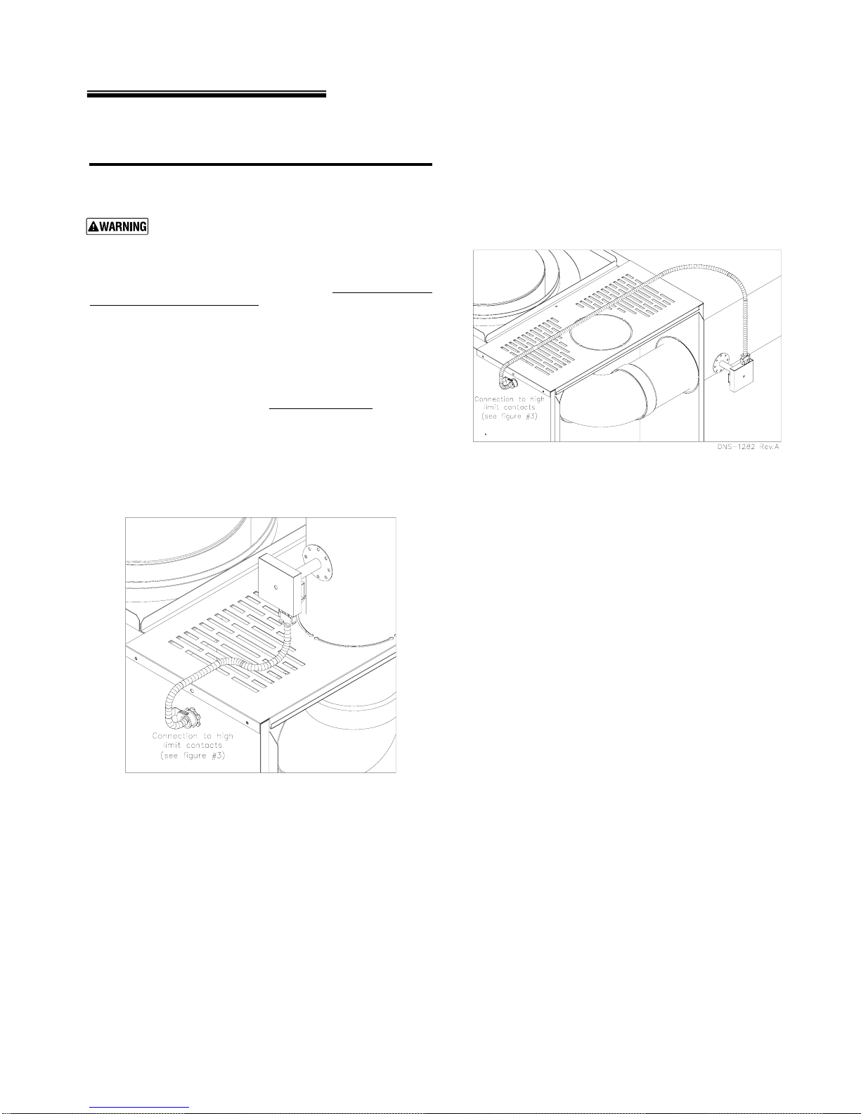
Refer to the figures 3 to 5 at section 6, Wiring Diagrams and detailed
instructions supplied with the BVSO for the installation and wiring
procedures.
It is also essential the the BVSO be maintained annually.
For more details refer to the instructions supplied with the device
itself, as well as the Maintenance Section.
Figure 1
Blocked Vent Shutt-Off device wiring
Installation : Upflow with Vertical exhaust
(Optional)
Figure 2
Blocked Vent Shutt-Off device wiring
Installation : Upflow with Horizontal exhaust
(Optional)
670-000-005/1010 7
Page 8
THB & TLB Oil Furnaces – Furnace Manual
3 Connect supply and return ducts
Duct sizing
Determine air flow CFM
The temperature rise through the furnace must not exceed 85o F and
should be at least 55
assume a temperature rise of 70
The sensible heat temperature change for cooling would be
approximately 27-30
approximately 18-21
To calculate the sensible heat temperature change (ΔT), you can
use the formula:
ΔT = BTU/h/(1.1 x CFM) Eq. 3-1
To calculate air flow when you know temperature change (ΔT), you
can use:
CFM = BTU/h/(1.1 x ΔT) Eq. 3-2
You can estimate air flow using the following rules of thumb:
Heating: 14 CFM per 1,000 BTU/h output Eq. 3-3
Cooling: 400 CFM per ton air conditioning Eq. 3-4
Determine the required air flow based on whichever is larger –
heating mode or air conditioning mode.
Examples:
1. What would the temperature rise be for a 100,000 BTU/h output
furnace with an air flow rate of 1,200 CFM?
Use Equation 3-1 since you know CFM and BTU/h:
ΔT = 100,000/(1.1 x 1200) = 76
• The temperature rise would be 76
• If the air enters the furnace at 70
furnace at 70
2. What would the air flow be to obtain a 70
120,000 BTU/h output furnace?
Use equation 3-2 since you know ΔT and BTU/h:
CFM = 120,000/(1.1 x 70) = 1,558 CFM
• The air flow would have to be 1,558 CFM to obtain a
temperature rise of 70
3. Estimate the required air flow for a 75,000 BTU/h output furnace
installed with a 2-ton air conditioning evaporator coil.
Heating mode air flow (use Equation 3-3):
CFM = 75 x 14 = 1,050 CFM
Cooling mode air flow (use Equation 3-4):
CFM = 2 x 400 = 800 CFM
• The larger number is 1,050 CFM (heating), so the duct
system should be sized for 1,050 CFM.
• The supply duct would need to be 16" round or a rectangular
equivalent such as 8" x 25" or 12" x 16", using Table 4,
page 9.
4. Estimate the required air flow for the same furnace installed with
a 4-ton air conditioning evaporator coil.
Heating mode air flow is still 1,050 CFM.
Cooling mode air flow (use Equation 3-4):
CFM = 4 x 400 = 1,600 CFM
• The larger number is 1,600 CFM (cooling), so the duct
system should be sized for 1,600 CFM.
• The supply duct would need to be 18" round or a rectangular
equivalent such as 8" x 36" or 12" x 21", using Table 4,
page 9.
o
F for comfort. When calculating air flow,
o
F.
o
F. Actual temperature change will be
o
F due to humidity of the air.
o
F
o
F.
o
o
F + 76o F = 146o F.
o
F.
F, it would leave the
o
F rise through a
Always check the size of existing ducts, particularly
if you are adding air conditioning. The air pressure
loss through the cooling evaporator coil reduces
available air flow. If the ducts are too small as well,
the system may not work satisfactorily on either
heating or cooling.
Determine duct dimensions
Table 4, page 9, and Table 5, page 10, provide typical round and
rectangular duct sizes for rectangular and flat oval galvanized ducts.
Do not apply these tables to size ductwork if the total equivalent
length of the duct exceeds approximately 100 feet. For longer
systems or for duct board, fiberglass-lined or flexible duct sizing, use
the ACCA Manual D or the ACCA duct sizing slide rule. These
tables are based on pressure loss of approximately 0.10 inch water
column per 100 feet equivalent length of duct.
Use Table 3 below to size or check sizing of takeoffs to supply
registers or return grills.
Verify the size and type of registers, diffusers and grills from the
manufacturer’s ratings. Do not exceed the recommended flow rate.
The pressure drop allowance for each should not exceed
approximately 0.05 inch water column.
Install a return air filter, sized per specifications on Section 12.
Use only a return air filter mounted to the furnace. Do not add
additional filters unless the duct system is carefully sized to allow for
the additional pressure drop.
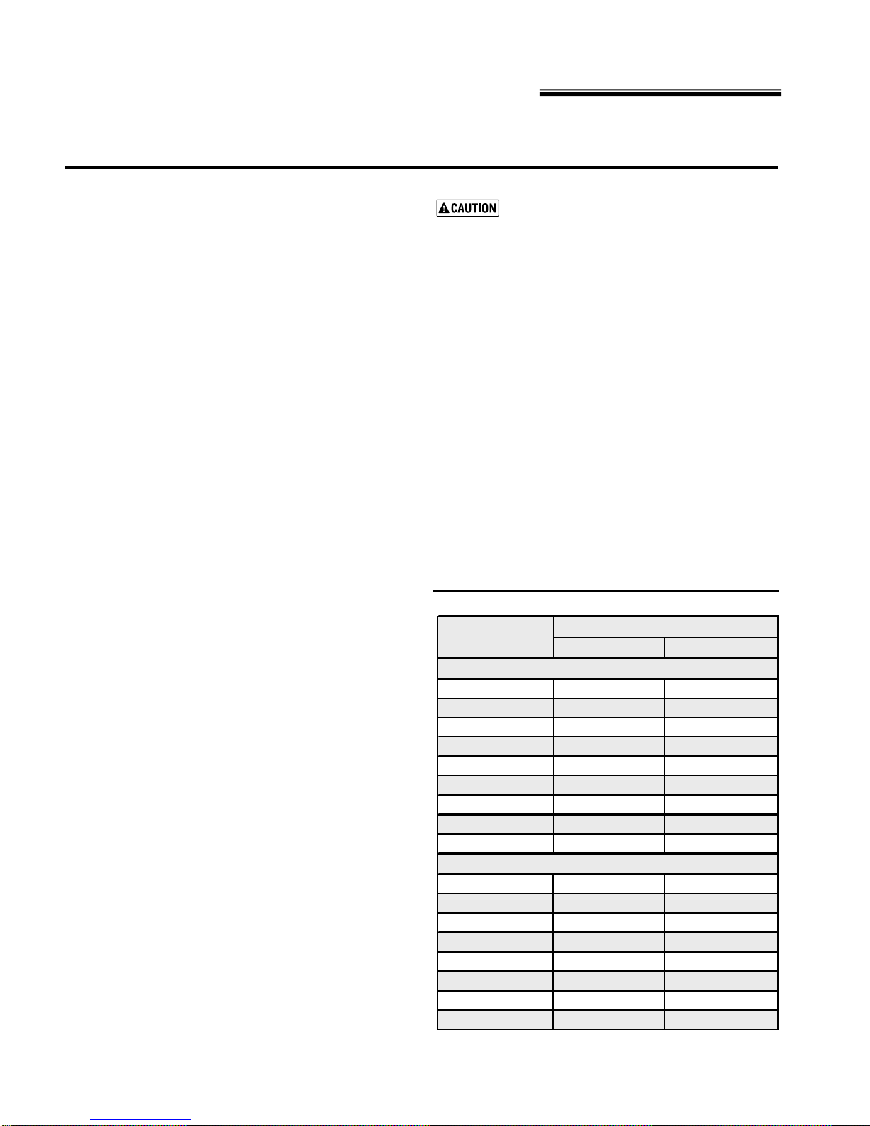
Table 3 Suggested maximum flow to takeoffs
TAKE-OFF SIZE
(Inches)
Sheet metal or ductboard
5 Round 60 45
6 Round 100 75
7 Round 140 110
8 Round 210 160
3 ¼ x 8 Stack 70 55
3 ¼ x 10 Stack 100 75
3 ¼ x 14 Stack 140 110
2 ¼ x 12 Stack 70 55
2 ¼ x 14 Stack 90 70
Flexible duct (keep bends to minimum)
6 Round 55 40
8 Round 120 90
10 Round 200 160
12 Round 320 250
14 Round 480 375
16 Round 660 530
18 Round 880 680
20 Round 1200 900
SUPPLY RETURN
CFM
8 670-000-005/1010
Page 9
THB & TLB Oil Furnaces – Furnace Manual
3 Connect supply and return ducts (continued)
Duct sizing (continued)
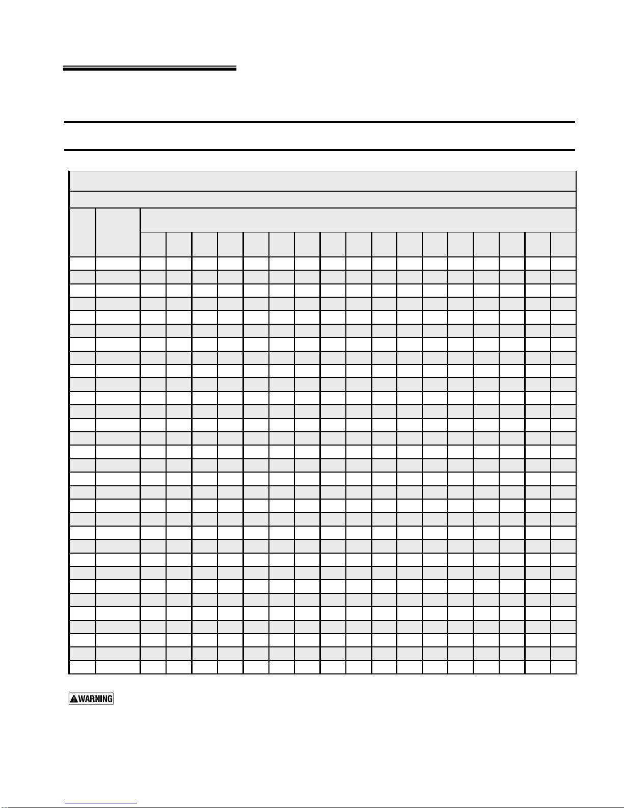
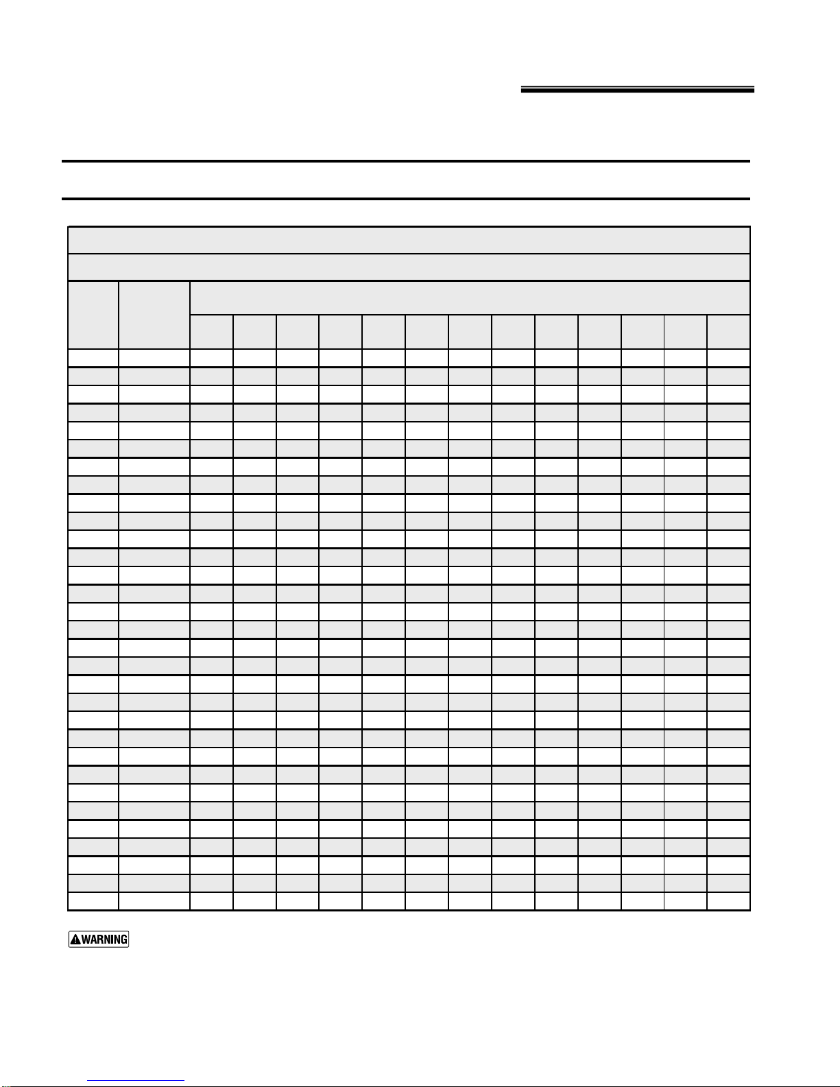
Table 4
Typical duct sizing for systems not over 100 feet equivalent length – round or rectangular galvanized
Typical duct sizing
(For approxim ately 0.10 inch w.c. i n a typical residenti al instal lation of galvani z ed metal duc t)
Round
CFM
duct
diameter4567891012141618202224262830
(inches)xxxxxxxxxxxxxxxxx
45
65
100
150
200
250
300
400
500
600
700
800
900
1000
1100
1200
1300
1400
1500
1600
1700
1800
1900
2000
2200
2400
2600
2800
3000
3500
4000
Rectangular duct equival ent sizes
Mini mum wi dt h
4
5
6
7
8
9
9
10
12
12
12
14
14
16
16
16
16
18
18
18
18
18
20
20
20
22
22
22
22
24
26
444-------------6544-------------
865544- - --------1297655544-------141198766544------181310987665544----20151210987665544---2619151311109876655544322318151312119876665555
3828221815131210987766655
46322520171514111098777666
523628231917151311109887766
5841312521191714121110988777
6445342823201815131110998877
72493830252219161412111099887
-5441332724211715131211109988
- 58443529252218161412111010 9 9 8
- 6347383127241916141312111010 9 9
- 685140342925201715141212111010 9
- 725443363027211816141312111110 9
- - 58 45 38 32 28 23 19 17 15 14 13 12 11 10 10
- - 61 48 40 34 29 24 20 17 16 14 13 12 11 11 10
- - 64 51 42 35 31 25 21 18 16 15 14 13 12 11 11
- - 68 53 44 37 32 26 22 19 17 15 14 13 12 12 11
- - - 5948413528232018161514131212
- - - 6452443830252219171615141312
- - - 6956474132272321191716151413
- - - - 61 51 44 34 29 25 22 20 18 17 15 15 14
- - - - 65 54 47 37 30 26 23 21 19 17 16 15 14
-----635442342926232119181716
-----726147393329262321201918
Do not apply this table for duct systems over approximately 100 equivalent feet length. For longer systems or systems using
other duct materials, refer to ACCA Manual D. Incorrectly sizing duct systems can result in unsafe or uncomfortable
operation.
(inches)
for duct heights
(inches)
of :
670-000-005/1010 9
Page 10
THB & TLB Oil Furnaces – Furnace Manual
3 Connect supply and return ducts (continued)
Duct sizing
Table 5
Typical duct sizing for systems not over 100 feet equivalent length – round or flat oval galvanized
(For approximately 0.10 inch w.c. i n a typical residenti al instal lation of galvani z ed metal duc t)
Round
CFM
45
65
100
150
200
250
300
400
500
600
700
800
900
1000
1100
1200
1300
1400
1500
1600
1700
1800
1900
2000
2200
2400
2600
2800
3000
3500
4000
duct
diameter3456789101214161820
(inches)xxxxxxxxxxxxx
Do not apply this table for duct systems over approximately 100 equivalent feet length. For longer systems or systems using
other duct materials, refer to ACCA Manual D. Incorrectly sizing duct systems can result in unsafe or uncomfortable
operation.
(continued)
4
5
6
7
8
9
9
10
12
12
12
14
14
16
16
16
16
18
18
18
18
18
20
20
20
22
22
22
22
24
26
Typical duct sizing
Flat oval duct equi val ent sizes
Mini mum width
65-----------
86----------1187---------161198--------211511108-------26181411109------302016131110------40262016141211-----4932241916141312----5938282219161513----694432252118161513----
-5036292420181614----
-5641322622201815----
- 634535292422191715 - - -
- 694938312623211816 - - -
- 755341332825221917 - - -
- - 58 44 36 30 26 24 20 18 - - -
- - 62 47 38 32 28 25 21 18 17 - -
- - 66 50 41 34 30 26 22 19 18 - -
- - 71 54 43 36 31 28 23 20 18 - -
- - - 57 46 38 33 29 24 21 19 - -
- - - 60 48 40 35 31 25 22 20 - -
- - - 63 50 42 36 32 26 23 21 19 -
- - - 67 53 44 38 33 27 24 21 20 -
- - - 73 58 48 41 36 29 25 23 21 -
----635244393227242221
----685648423429252322
-----6051443630272423
-----6454473832282624
------63544336322826
------71614840353129
(inches)
for duct heights
(inches)
of :
10 670-000-005/1010
Page 11
THB & TLB Oil Furnaces – Furnace Manual
4 Venting
General venting requirements
Failure to follow all instructions can result in flue gas
spillage and carbon monoxide emissions, causing
severe personal injury or death.
Inspect existing chimney before installing furnace.
Clean chimney thoroughly. Replace or repair
chimney if visual inspection indicates chimney may
be unsuitable for use. Insufficient draft can cause
flue gas leakage and carbon monoxide emissions.
Failure to clean or replace perforated pipe or tile
lining and/or patch mortar and joints can cause
severe personal injury or death.
• THB and TLB furnaces are designed to operate with an over-fire
draft of -0.01" to –0.02" w.c. Proper draft for these oil furnaces
may be achieved using either a conventional chimney (natural
draft) or a power vent (sidewall) system that has been properly
designed for use with oil equipment. Power vent manufacturer’s
instructions must be followed.
• Use vent material approved by local codes for oil-fired burners.
In their absence, refer to:
• NFPA 31, Installation of Oil-Burning Equipment.
• NFPA211, Standard for Chimneys, Fireplaces, Vents and
Solid Fuel Burning Appliances.
• In Canada, refer to CSA B139, Installation Code for Oil-
Burning Equipment.
• NFPA-211 requires chimney to be lined before being
connected to furnace.
• To prevent downdrafts, extend chimney at least 3 feet above
highest point where it passes through roof and 2 feet higher than
any portion of building within 10 feet. Increase chimney crosssectional area and height at least 4% per 1,000 feet above sea
level.
• Provide minimum clearances from vent (flue) pipe to
combustible material:
• Single-wall vent – 18 inches minimum
• Type "L" double-wall vent – 6 inches minimum
• Provide a chimney no smaller than that listed in Table 6.
Oversized chimneys, outside masonry chimneys
and/or de-rated inputs can result in condensation in
chimney.
Connect venting
Long horizontal vent runs, excessive number of tees
and elbows, or other obstructions restricting
combustion gas flow can result in the possibility of
condensation, flue gas leakage and carbon
monoxide emissions, which can lead to severe
personal injury or death.
1. The horizontal vent must slope upwards, away from the furnace,
a minimum of ¼ inch per foot.
2. Connect full-sized venting when possible. See Table 6.
3. Connection must be made above bottom of chimney to avoid
blockage. Vent pipe must not enter chimney far enough to cause
obstruction. Use thimble or slip joint where vent pipe enters
chimney to allow removal for cleaning.
4. When burner and furnace are properly installed, draft overfire
will be approximately –0.01" to –0.02" w.c. Install barometric
Connect venting (continued)
control in vent, per control manufacturer’s instructions, when
excess draft needs to be relieved or to comply with applicable
codes and regulations. Use draft gauge to adjust proper
opening.
5. An induced draft fan for the chimney may be necessary if:
• Excessive resistance to flow of combustion gases can be
expected.
• Cross-sectional area of chimney is smaller than minimum
recommended.
• Chimney height is less than recommended.
• When using induced draft fan, seal all vent joints and
interlock burner with fan operation.
Table 6 Minimum chimney/vent size
Furnace
Model
number
THB/TLB-105 6 “ 6 “ x 6” 6 “ 15’
Minimum
vent
diameter
Minimum chimney
size
Rectangular
(minimum inside
dimensions)
Round
Minimum
Chimney
height
Vent dampers
Do not install a thermal-type vent damper on this
furnace. Failure to comply could result in severe
personal injury, death or substantial property
damage.
If vent damper is required, use only a motorized vent
damper, installed and wired to the furnace following
the vent damper manufacturer’s instructions.
Barometric draft control
Install barometric control in vent, per control manufacturer’s
instructions, when excess draft needs to be relieved or to comply
with applicable codes and regulations. Use draft gauge to adjust
proper opening.
1. Install barometric draft control in vent pipe at least one foot from
the furnace vent connection, preferably in the highest part of the
vent pipe before the vent enters the chimney. If headroom
doesn’t provide enough clearance to locate the control at least
one foot from the vent connection, install an elbow at the furnace
and mount the control in a horizontal pipe at least one foot from
the elbow. Install an elbow after the control to turn vertically.
2. To operate correctly, the barometric draft control must be
located in the same room as the furnace.
3. Ensure the barometric draft control is accessible. Adjust the
damper to obtain the correct overfire draft, as described in this
manual and the burner manual.
670-000-005/1010 11
Page 12
THB & TLB Oil Furnaces – Furnace Manual
5 Connect fuel oil piping
General oil piping requirements
• Location and installation of oil tanks, oil piping and burners must
follow:
• NFPA 31, Standard for the Installation of Oil-Burning
Equipment.
• In Canada, CSA B139, Installation of Oil-Burning
Equipment.
• Local codes and regulations.
• Information provided with burner and fuel pump.
• If any part of fuel oil tank is above level of burner, an anti-siphon
device must be used to prevent flow of oil in case of oil line
break.
• Support oil lines as required by codes.
• Make tank connections with swing joints or copper tubing to
prevent breaking in case the tank settles. Make swing joints so
they will tighten as tank settles. Non-hardening pipe joint
compounds should be used on all threads.
Do not use Teflon tape as an oil pipe sealant. It can
cause valves to fail, creating hazards. Use only flare
fittings. Do not use compression fittings. Failure to
comply could result in severe personal injury, death
or substantial property damage from oil leakage
and/or fire hazard.
• Underground pipe must be ru n in a casing to prevent oil leaking
into ground or under floor. Check local codes for information.
Oil piping connection at burner
• Connect oil line to burner using a flare fitting.
Use of any connection other than a flare fitting at the
oil connection to the burner could result in a fuel oil
leak, with the potential for severe personal injury,
death or substantial property damage.
• See local codes for appropriate arrangement and piping of filter,
control valves, etc. connecting to oil tank.
• Refer to burner manual for oil system requirements. Verify that
suction lift does not exceed stated limit. Where lift exceeds limit
for a one-pipe system, use a two-pipe system as directed in
burner manual.
6 Wire furnace & burner
Electric shock hazard. Can cause severe personal
injury or death if power source, including service
switch on furnace, is not disconnected before
installing or servicing
Wire burner
The burner harness is factory-wired to the furnace at the factory.
Plug the burner harness into the mating burner connector to wire the
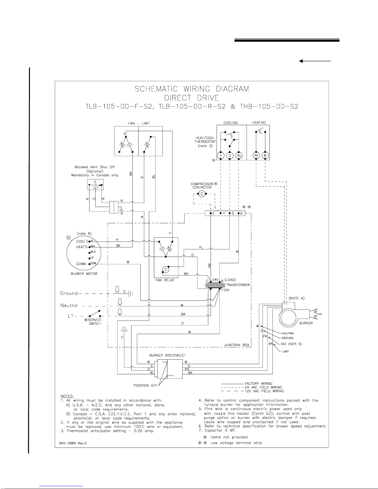
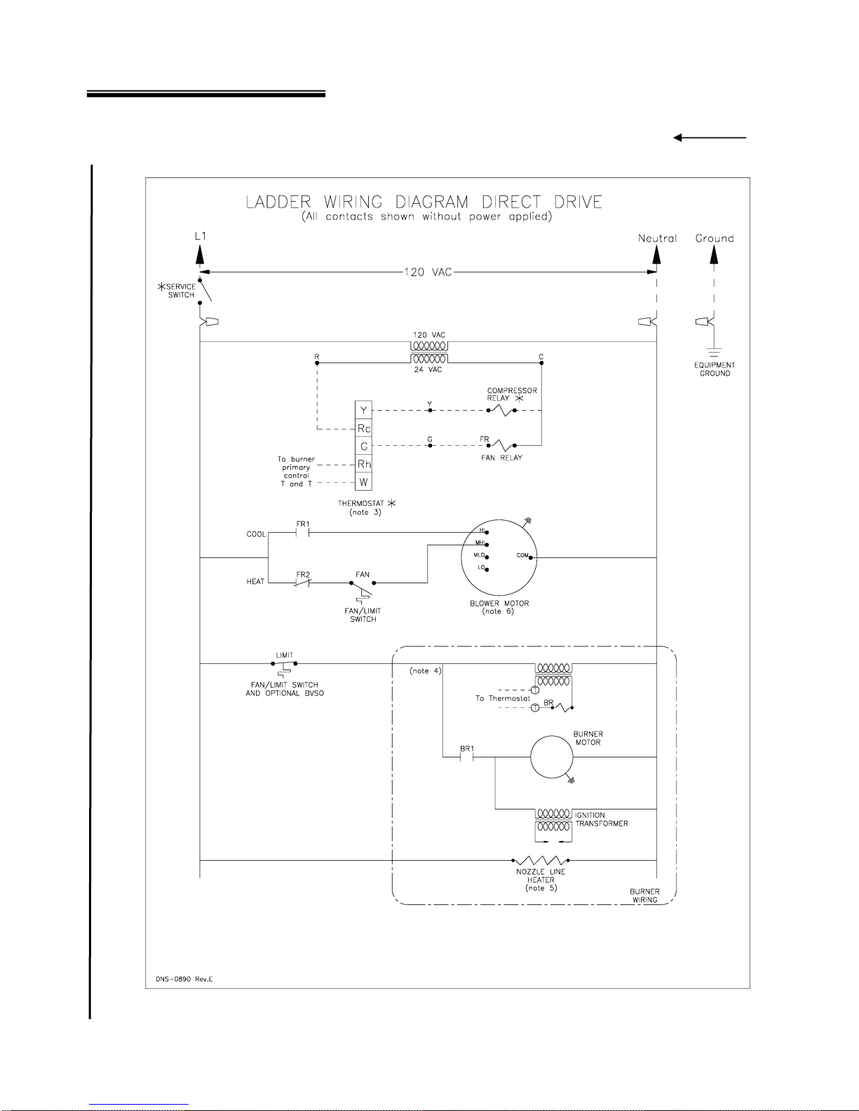
burner. Refer to the wiring diagram on pages 14 and 15 for further
information.
Install and wire thermostat
Locate the room thermostat on an interior wall in the natural
circulating path of room air. Do not locate thermostat so it is exposed
to cold air infiltration, drafts from windows or doors, air currents from
supply or return air registers, behind obstructions, on a shelf, in a
closet, or in a corner.
Ensure the thermostat won’t be exposed to heat from nearby
fireplace, radio, television, lamp or rays from the sun. Do not mount
thermostat on a wall over a supply or return duct, chimney or vent.
Wire thermostat to furnace and set thermostat anticipator as shown
on wiring diagram, pages 14 and 15.
Connect power wiring
All wiring must conform to:
• National Electrical Code, ANSI/NFPA 70, latest edition and any
additional national, state or local codes.
• In Canada, CSA C22.1 Canadian Electrical Code Part One and
any local codes.
• Wiring must be N.E.C. Class 1. If original wire as supplied with
furnace must be replaced, type 105
be used. Supply wiring to furnace must be sized for the load
required (see Section 12)
• Provide electrical ground at furnace as required by codes.
Connect 120 VAC/60 Hertz, single phase separate electrical line
from the main house panel to the power leads in the furnace
electrical box as shown on wiring diagram, pages 14 and 15.
Provide a fused disconnect in the power wiring, following all local
codes.
Ensure the wire size and type are adequate for the electrical load
(see Section 12 and furnace nameplate for value).
Limit control
The furnace is equipped with a fan switch/limit control. This control
limits the air leaving the heat exchanger to 200
switch continues fan operation until the air drops to a preset
temperature. For most installations, set the blower ON setting at
o
F and blower OFF setting at 90o F. If a longer cool down period
110
is desired, lower the OFF setting.
o
C wire or equivalent must
o
F or less. The fan
12 670-000-005/1010
Page 13
THB & TLB Oil Furnaces – Furnace Manual
6 Wire furnace & burner
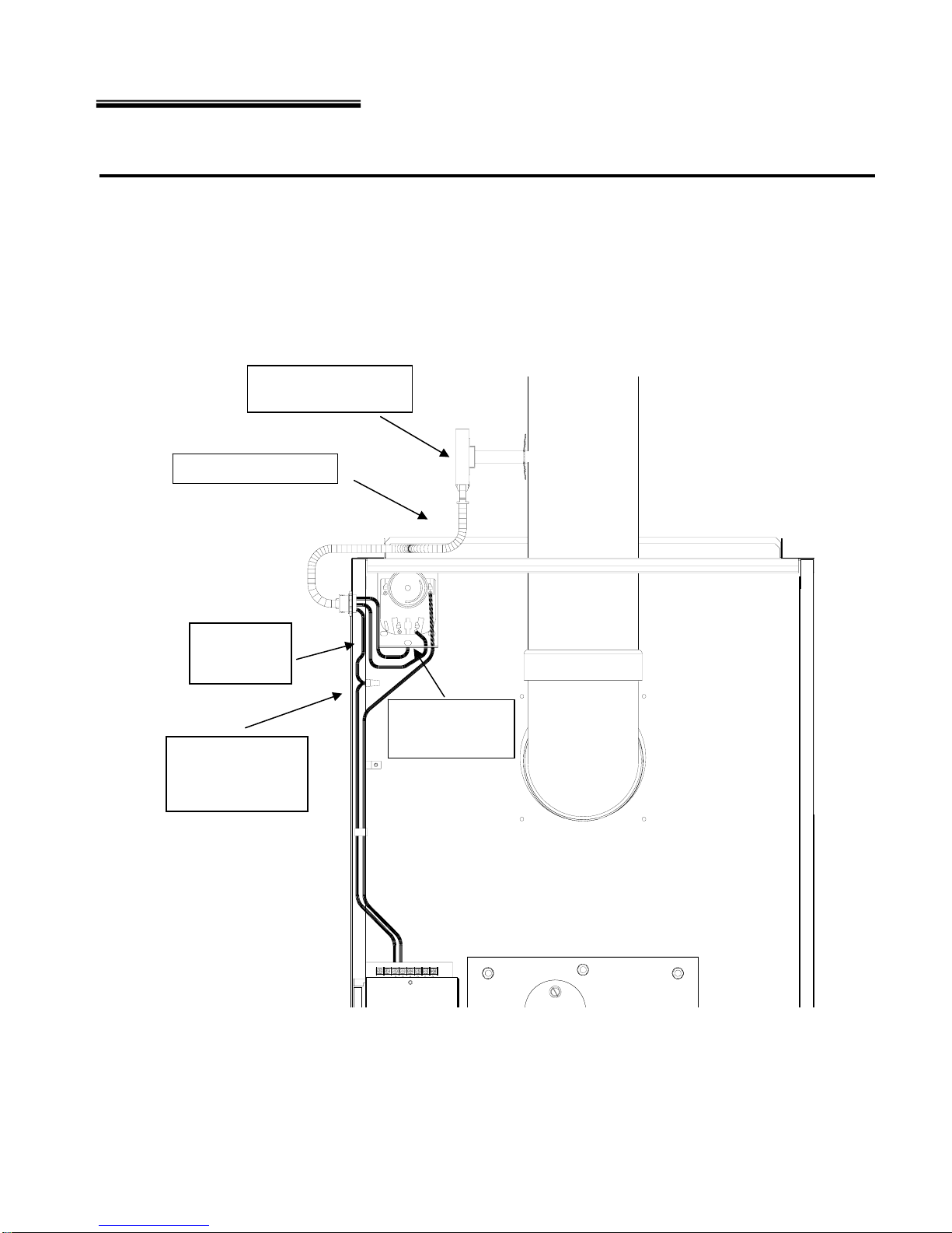
Figure 3
Blocked Vent Shut-Off device wiring
(Optional)
Electrical kit supplied
Blocked Vent Shutt-Off
device BVSO
Connect one
red wire to
limit switch
Disconnect red wire
from limit switch
and connect to one
red wire from BVSO
Connect the green
ground wire to a
cabinet screw
670-000-005/1010 13
Page 14
THB & TLB Oil Furnaces – Furnace Manual
6 Wire furnace & burner (continued)
Figure 4 Wiring – THB & TLB furnaces with direct-drive blowers
14 670-000-005/1010
Page 15
THB & TLB Oil Furnaces – Furnace Manual
6 Wire furnace & burner (continued)
Figure 5 Wiring – THB & TLB furnaces with direct-drive blowers
670-000-005/1010 15
Page 16
THB & TLB Oil Furnaces – Furnace Manual
7 Start up
Follow information below to prevent severe
personal injury, death or substantial property
damage:
• Do not use gasoline, crankcase drainings or any oil
containing gasoline. See burner manual for proper
fuel oil.
• Do not attempt to start b urner when excess oil has
accumulated, when unit is full of vapor or when
combustion chamber is very hot.
• Do not start burner unless collector box, venting
and burner mounting plate are secured in place.
• Never burn garbage or paper in the furnace.
• Never leave combustible material around it.
To start furnace
1. Factory burner adjustment and settings may not be suitable for
specific job conditions. Refer to burner manual for burner start
up, adjustment and checkout procedures.
2. Set room thermostat to call for heat.
3. Start burner as described in burner manual.
4. The furnace blower will delay for a short time after burner
starts, until the limit/fan switch senses air temperature above
the fan ON setting.
5. Set room thermostat to its lowest setting. Burner should turn
off.
6. Furnace blower will continue to run until the limit/fan switch
senses air temperature below the fan OFF setting.
7. Set the room thermostat to call for heat again. Allow furnace to
heat to design temperature. Then adjust burner for correct
combustion, using combustion test equipment. Adjust burner
for:
Draft: -0.01 to –0.02 inches water column draft in furnace
combustion chamber.
: between 10 % and 11½ %, with 0 smoke.
CO
2
8 Checkout procedure
Furnace selection
..1. Heat loss ............................... BTU/h at ............ oF outdoor
design temperature.
..2. Furnace model.......................................................................
output .......................... BTU/h.
..3. Burner model ........................................................................
o
nozzle: ............. gph ................
..4. Burner pump pressure ........................................ psig.
type............... .
To start furnace
Make final burner adjustments using combustion
test equipment to assure proper operation.
8. Check furnace and duct system for proper operation and
conditions.
9. Inspect vent system for proper operation.
10. To set limit/fan switch:
The blower operates until the air temperature drops below the
fan OFF setting. If the air at the supply registers is too warm at
blower start up or shutdown, lower the fan OFF and ON
settings on the limit/fan switch.
To check operation of the limit switch, slide a piece of
cardboard into the furnace filter slot. After a few minutes of
operation (not more than 5 minutes), the burner should shut off
(limit switch open). The blower will operate until the furnace
cools down. Remove cardboard when finished.
11. Complete testing of the burner cad cell control using the
instructions in the burner manual.
(continued)
To shut down furnace
1. Set the room thermostat to its lowest setting.
2. Turn off the disconnect switch in the 120-VAC power line to the
furnace.
3. If the burner will be shut down for an extended time, tightly
close all oil valves.
4. Refer to burner manual for any additional instructions.
Furnace installation
..5. Furnace level and all legs in contact with floor?
..6. Return and supply ducts securely attached to furnace?
..7. Fuel filter and fuel lines installed per burner manual and
inspected?
..8. Furnace and burner wired per wiring diagram?
..9. 120 VAC wiring: type................. size ................ AWG.
16 670-000-005/1010
Page 17
THB & TLB Oil Furnaces – Furnace Manual
8 Checkout procedure (continued)
Vent and combustion air
..10. Existing chimney/vent system inspected and in good
condition?
..11. New vent piping installed, sealed and in good condition?
..12. Vent sizing checked against furnace manual and codes?
Ductwork
.. 13. Duct sizing checked against furnace manual and/or ACCA
Manual D?
.. 14. Supply and return registers checked for size based on air
flow?
..15. Balancing dampers installed as needed?
..16. Ductwork sealed and insulated as needed?
Furnace operation
..17. Clean air filter in place?
..18. Temperature rise through furnace checked (not to exceed
..19. Thermostat heat anticipator set per wiring diagram?
..20. Burner started and tested per burner manual?
.. 21. Proper draft and burner flame? Final adjustment made with
o
85
F) and blower speed adjusted if necessary?
combustion test equipment?
Furnace operation (continued)
..22. Air purged from oil piping? Piping checked for leaks?
..23. Burner sealed to furnace and nuts tight? Burner harness
securely plugged in?
Obtain gas-tight seal at burner flange, cleanout
plates and/or flue collector box to prevent possible
flue gas leakage and carbon monoxide emissions,
leading to severe personal injury or death.
..24. Limit control tested per “To start up” in this manual?
..25. Furnace cycled with thermostat? Raise to highest setting
and verify furnace goes through normal start up cycle. Lower
to lowest setting and verify furnace goes off.
..26. Observed several operating cycles for proper operation?
..27. Set room thermostat (s) to desired room temperature?
After installation
..28. Completed “Installation and service certificate” below?
.. 29. Reviewed Owner’s information in this manual with owner or
maintenance person and instructed person to keep for future
reference?
..30. Replaced all instructions provided with furnace for future
reference?
Installation and service certificate
Furnace model__________________________________________________ Series _______________________
Serial number_______________________________________Date installed_____________________________
Installation instructions have been followed.
Checkout sequence has been performed.
Above information is certified to be correct.
Information received and left with owner/maintenance person.
Installer _______________________ _______________________ _____________________
(company) (address) (phone)
________________________________________________
(installer’s signature)
670-000-005/1010 17
Page 18
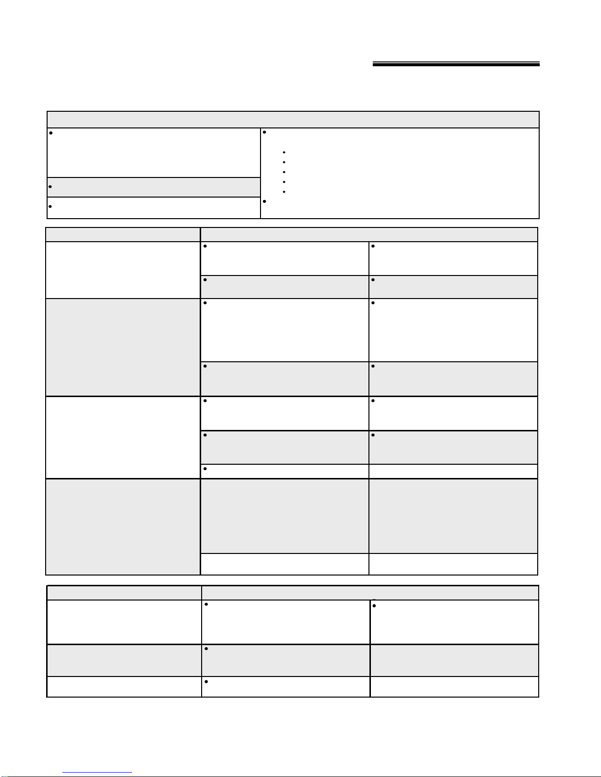
THB & TLB Oil Furnaces – Furnace Manual
9 Troubleshooting
Before beginning these troubleshooting procedures, ALWAYS :
Check 120 volt supply to furnace. If there is no supply To successfully service the oil furnace, you must
voltage, check fuses and service switch. CAUTION : have these instruments :
When testing electrical equipment, always follow smoke tester
standard electrical safety procedures.
Make sure thermostat is calling for burner operation.
Check oil supply and make sure all valves are open.
Symptom – Burner
Burner motor does not start.
Burner short cycles or locks out on
primary relay safety.
Unable to achieve clean combustion
by setting air adjustments.
To check CAD cell operation, use the
following procedure :
Symptom – Furnace blower
Furnace blower will not start.
Blower cycles on and off after the
burner has shut down.
Blower short cycles on limit control.
carbon-dioxide (CO
draft gauge (scale should read from -.01” w.c. to -.25” w.c.)
volt/OHM/milliamper multimeter
pressure gauge capa ble of reading 0-150 lb/sq. inch (for oil only)
Be familiar with these instruments as well as the burner
manufacturer's recommended settings.
Possible corrections :
Check fuses and make sure service switch is
on.
Check for line voltage into furnace junction
box.
If the primary relay control is not popping out
the reset button, measure the milliamperage at
the thermo stat and set the heat-anticipator
accordingly. Also check wiring from the
thermostat to the burner.
Check nozzle and electrode position. Check ignition transformer output
(Reference burner manufacturers
instructions).
Check tube insertion and alignment. Check nozzle and electrode position
Replace nozzle. Check pump pressure (varies with
Check overfire draft.
1. Remove CAD cell leadwires from the f-f
terminals on the primary safety control, then
start burner. Shortly after burner starts, place
a temporary jumper between terminals f-f.
Connect ohmeter across CAD cell leadwiresresistance should be under 1,600 ohms.
2. Stop burner and remove temporary jumper.
Possible corrections :
Check wiring from Fan and Limit control. See
if blower motor will run when it is switched on
manually at the thermostat sub-base (if subbase is installed).
o
Adjust fan "off" setting to 90
"on" setting to 110
Return ducts may be undersized.
o
.
and adjust fan
) or oxygen (O2) analyzer
2
Check for voltagefrom primaryrelay to burner
motor. Make sure the primary relay has not
locked out on safety.
Make sure the thermostat is calling for heat
and tha t th e wiring to the thermostat is correct.
Check the alignment of the cad cell to assure
it is aimed at the fire.
(Reference burner manufacturer's
instructions).
manufacturer and application; see burner
manual).
3. With burner off, check dark cell resistance
across CAD cellleadwires. Resistance should
be greater than 20,000 ohms. If cell
resistances are different from above, recheck
wiring and location of cell, etc. If necessary,
replace plug-in portion of cell.
Check for 120V to the blower motor. If
present, replace motor.
18 670-000-005/1010
Page 19
THB & TLB Oil Furnaces – Furnace Manual
10 Service and maintenance
Follow the “Service and maintenance” procedures given throughout this manual and in component literature shipped with the
furnace. Failure to perform the service and maintenance could result in damage to the furnace or system. Failure to follow the
directions in this manual and component literature could result in severe personal injury, death or substantial property
damage.
The furnace should be inspected and started annually, at the beginning of the heating season, only by a qualified service
technician. In addition, the maintenance and care of the furnace outlined in the table below, and explained on the following
pages must be performed to assure maximum furnace efficiency and reliability. Failure to service and maintain the furnace
and system could result in equipment failure.
This furnace contains fiberglass and ceramic fiber materials. These materials require special attention. Please refer to the
WARNING and guidelines given on page 20. Failure to comply could result in severe personal injury, death or substantial
property damage.
Service technician annual maintenance/ st ar t up
(see following pages and burner manual for instructions)
Service and mai ntenance
Annual start up
Furnace and air system
Consult with homeowner to see if there were any Check sequence of operation
problems with furnace or system during the prior Check flame characteristics
heating season (or cooling season) Perform combustion checks/tests per burner manual and
Clean, inspect, and lubricate blower motor and wheel furnace manual
Check condition of electrical wiring and tightness of
terminals an d connectors Check thermo stat heat anticipator setting
Clean and inspect heat exchanger and combustion Check safety controls (high-temperature limit switch, flame
chamber
Clean and inspect system accessories
Check temperature rise
cutoff time, etc.)
Check operation
Vent system
Clean and inspect flue pipe, chimney/vent, and draft regulator
Fuel oil system
Check oil tank and piping for leaks
Replace oil filter
Oil burner
Clean and inspect oil burner assembly
Bleed system of air (single-pipe system)
Check oil pump pressures
Check combustion air ducts, grilles, etc. (if applicable)
670-000-005/1010 19
Page 20

THB & TLB Oil Furnaces – Furnace Manual
Handling ceramic fiber and fiberglass materials
HANDLING OR REMOVAL OF COMBUSTION CHAMBER
The combustion chamber in this product contains ceramic fiber materials.
Ceramic fiber can be converted to cristobalite in very high high temperature
applications. The International Agency for Research on Cancer (IARC) has
concluded, “Crystalline silica inhaled in the form of quartz or cristobalite from
occupational sources is carcinogenic to humans (Group 1)”.
Avoid breathing dust and contact with skin and eyes.
• Use NIOSH certified dust respirator (N95). This type of respirator is based on the OSHA
requirements for cristobalite at the time this document was written. Other types of respirators
may be needed depending on the job site conditions. Current NIOSH recommendations can
be found on the NIOSH web site at http://www.cdc.gov/niosh/homepage.html
approved respirators, manufacturers, and phone numbers are also listed on this web site.
• Wear long-sleeved, loose fitting clothing, gloves, and eye protection.
Apply enough water to the combustion chamber lining to prevent airborne dust.
Remove combustion chamber lining from the furnace and place it in a plastic bag for disposal.
Wash potentially contaminated clothes separately from other clothing. Rinse clothes washer
thoroughly.
NIOSH stated First Aid.
Eye: Irrigate immediately
Breathing: Fresh air.
HANDLING OR REMOVAL OF FIBERGLASS WOOL – OR –
INSTALLATION OF FIBERGLASS WOOL OR COMBUSTION CHAMBER :
This product contains fiberglass jacket insulation and ceramic fiber materials in
combustion chamber. Airbone fibers from these materials have been listed by
the State of California as a possible cause of cancer through inhalation.
Avoid breathing dust and contact with skin and eyes.
• Use NIOSH certified dust respirator (N95). This type of respirator is based on the OSHA
requirements for fiberglass wool at the time this document was written. Other types of
respirators may be needed depending on the job site conditions. Current NIOSH
recommendations can be found on the NIOSH web site at
http://www.cdc.gov/niosh/homepage.html
phone numbers are also listed on this web site.
• Wear long-sleeved, loose fitting clothing, gloves, and eye protection.
Operations such as sawing, blowing, tear out, and spraying may generate airbone fiber
concentration requiring additional protection.
Wash potentially contaminated clothes separately from other clothing. Rinse clothes washer
thoroughly.
NIOSH stated First Aid.
Eye: Irrigate immediately
Breathing: Fresh air.
. NIOSH
. NIOSH approved respirators, manufacturers, and
20 670-000-005/1010
Page 21
THB & TLB Oil Furnaces – Furnace Manual
10 Service and maintenance (continued)
Service/maintenance procedures
To lubricate and inspect blower motor
DO NOT over-oil motors. Adding too much oil can
damage the motor bearings, resulting in blower
motor failure.
Belt-drive motor – Oil annually using 3 drops of S.A.E. #10 oil (or
other if specified by motor manufacturer). Blower bearings are
permanently lubricated and do not require oiling. Verify that the
blower, motor pulleys and belt are in good condition. Replace if
necessary.
Direct-drive motor – Oil annually using 2 drops of S.A.E. #10 oil (or
other if specified by motor manufacturer). Oiling is normally not
required until beginning of third year of operation.
Clean blower wheel – Vacuum dust from blower wheel blades and
surrounding area.
To clean heat exchanger
The heat exchanger must be cleaned and inspected
at least once each year. Operating the furnace with
a fouled or leaking heat exchanger could result in
severe personal injury, death or substantial property
damage.
The combustion chamber contains ceramic fiber
materials. Wear a NIOSH-approved respirator while
cleaning the furnace and follow WARNING on page
20 for proper handling.
1. Remove the burner and mounting plate.
2. Inspect the heat exchanger using a mirror insert ed through the
burner opening.
3. Using a brush on a flexible handle, loosen the soot on the inside
of the heat exchanger.
4. Remove the soot with a vacuum. Be careful not to damage the
combustion chamber while cleaning the heat exchanger.
5. Remove the heat exchanger cleanout covers of flue collector
box. Using a brush on a flexible handle, loosen the soot from the
heat exchanger surfaces. Remove as much soot as possible
using a vacuum.
6. Replace cleanout covers.
7. Inspect combustion chamber and replace with a new one if
chamber is damaged in any way.
8. Re-install burner and mounting plate.
Obtain gas-tight seal at burner flange and cleanout
plates to prevent possible flue gas leakage and
carbon monoxide emissions, leading to severe
personal injury or death.
Inspect vent system
Thoroughly inspect the entire vent system at least annually,
including horizontal vent pipe and chimney or vertical vent. Ensure
vent system is repaired or replaced if necessary before placing
furnace in operation.
Oiled-bearing burner motors
The burner may need to be lubricated if motor is equipped with oiling
cups. Refer to burner manual for specific instructions. If instructed,
apply a few drops only of S.A.E. 20 detergent oil (never use
household oils). Do not attempt to “fill up” the oil cup. Over-oiling can
damage the motor.
Annual start up
Follow information below to prevent severe personal
injury, death or substantial property damage:
• Do not use gasoline, crankcase drainings or any oil
containing gasoline. See burner manual for proper
fuel oil.
• Do not attempt to start burner when excess oil has
accumulated, when unit is full or vapor or when
combustion chamber is very hot.
• Do not start burner unless collector box, vent and
burner mounting door are secured in place.
• Never burn garbage or paper in the furnace.
• Never leave combustible material around it.
To start furnace
1. Factory burner adjustment and settings may not be suitable for
specific job conditions. Refer to burner manual for burner start
up, adjustment and checkout procedures.
2. Set room thermostat to call for heat.
3. Refer to burner manual for start up.
4. The furnace blower will delay for a short after burner starts, until
the limit/fan switch senses air temperature above the fan ON
setting.
5. Set room thermostat to its lowest setting. Burner should turn off.
6. Furnace blower will continue to run until the limit/fan switch
senses air temperature below the fan OFF setting.
7. Set the room thermostat to call for heat again. Allow furnace to
heat to design temperature. Then adjust burner for correct
combustion, using combustion test equipment. Adjust burner for:
Draft: -0.01 to –0.02 inches water column draft in furnace
combustion chamber.
: between 10 % and 11 ½ %, with 0 smoke.
CO
2
Make final burner adjustments using combustion test
equipment to assure proper operation.
8. Check furnace and duct system for proper operation and
conditions.
9. Inspect vent system for proper operation.
10. To set limit/fan switch:
The blower operates until the air temperature drops below the
fan OFF setting. If the air at the supply registers is too warm at
blower start up or shutdown, lower the fan OFF and ON settings
on the limit/fan switch.
To check operation of the limit switch, slide a piece of cardboard
into the furnace filter slot. After a few minutes of operation (not
more than 5 minutes), the burner should shut off (limit switch
open). The blower will operate until the furnace cools down.
Remove cardboard when finished.
11. Complete testing of the burner cad cell control using the
instructions in the burner manual.
670-000-005/1010 21
Page 22

THB & TLB Oil Furnaces – Furnace Manual
10 Service and maintenance
(continued)
Optional Blocked vent shut off (BVSO) cleaning
For continued safe operation, the Blocked Vent Shut Off System
(BVSO) is required to be inspected and maintained annually by a
qualified agency.
1. Disconnect the power to the appliance;
2. Remove the two screws holding on the BVSO assembly
cover;
3. Remove the cover;
4. Remove the two screws holding the thermal switch to the
assembly base;
5. Without removin g the electrical wires, remove the thermal
switch and remove any build-up from the thermal switch
surface;
Do not dent or scratch the surface of the
thermal switch. If the thermal switch is
damaged, replacement is required.
6. Clear and remove any build-up or obstruction inside the
heat transfer tube;
7. Re-mount the thermal switch to the assembly base;
8. Re-attach the assembly cover with the screws removed in
step 2;
9. Re-establish power to the appliance.
22 670-000-005/1010
Page 23
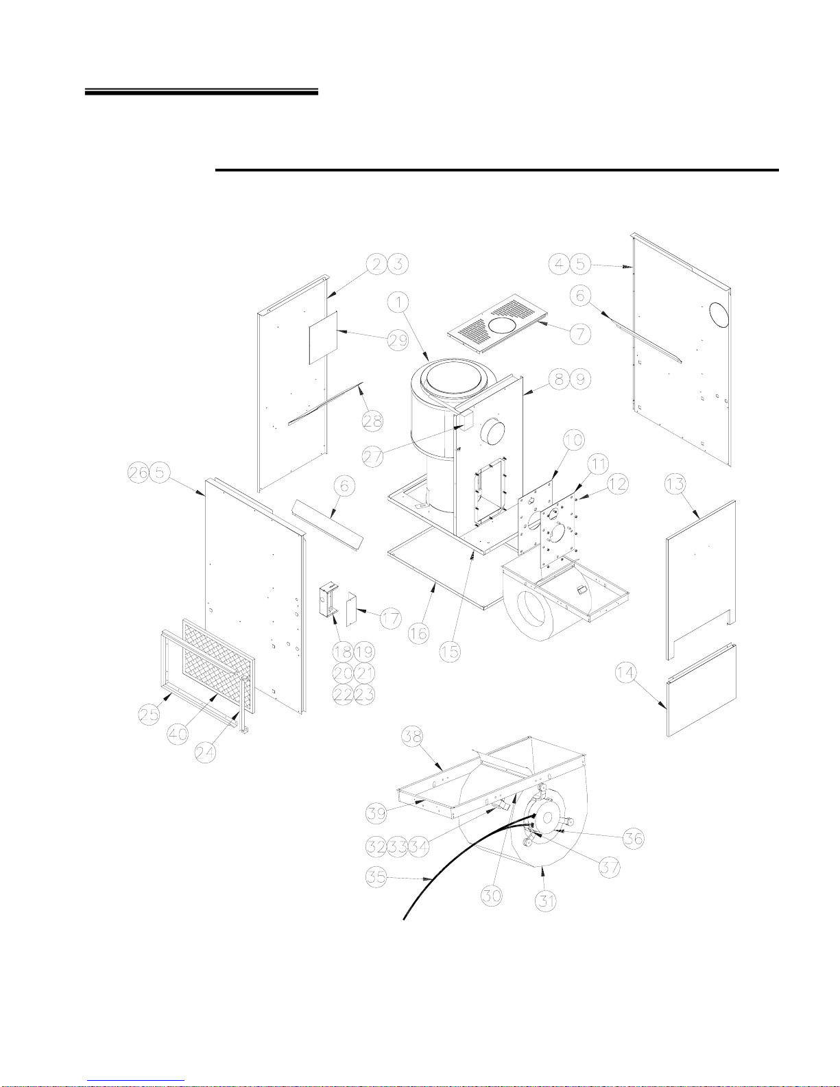
THB & TLB Oil Furnaces – Furnace Manual
11 Components and replacement parts
Figure 6 Model THB furnaces – Component locations
B50106A
670-000-005/1010 23
Page 24
r
THB & TLB Oil Furnaces – Furnace Manual
11 Components and replacement parts (continued)
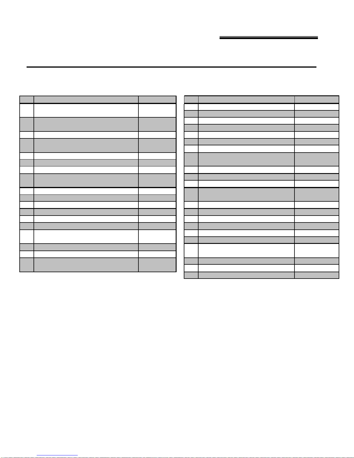
Model THB furnaces – Parts list
I t em Par t des c r iption Part numbe r Item Part description Part numbe
Complete heat exchanger 19 Terminal strip, 4 positions L05F009
1
(Combustion chamber included) 20 Transformer 120/24 VAC / 40 V A L01F009
Rear panel assembly 21 Relay SPDT 24VAC L01H009
2
(items 3, 28 & 29 included) 22 Electrical wire harness (burner) B02915
3 Rear panel ins ulation B 03107 23 Electrical wire harness (fan limit) B02917
R ight s ide panel assembl y 24 F ilter r ac k access B01696-0 1
4
(it em 5 in cl ud ed) 2 5 Fil t er ra c k "U" f r am e B01695-01
5 Side panel insulation B 03106 Left side panel assembly
6 Baffle, side B03061 (item 5 included)
7 Top front panel B03057 27 Fan limit control R02I002
Fr ont di v ider panel 28 Rear, ba ffl e B03062
8
(item 9 included) 29 Heat shield baffle B03060
9 Front divider insulation B03108 Blower assembly
10 Burner gasket B03071 (items 31,32,33,34 & 36)
11 Burner plate B03105 31 Blower 100-10T B03720-04
12 Hexagonal flange nut 3/8-16nc brass F07O001 32 5 MF capacitor L01I001
13 Front do or B03109 33 C apacitor holder B01024
14 Lower front door B03110 34 Rubber cap capacitor L99Z007
Blower di v ider pane l 35 E lectr ic al wire harness (blow er ) B02916
15
(blower slides included) 36 1/3 HP motor with legs B01890-01
16 Fl oor B03102 Belly band assembly
17 Electr ic al box c ove r B02978 (band, l egs, nuts & bolts incl uded)
Electrical box assembly 38 Blower slides B01681
18
(items 19,20,21,22 & 23 included) 39 Electrical box holder plate B01682
B03037- 01
B03101
B03100- 01
B03104
B03103
B02977
26
30
37
B03100-02
B02581-01
B01888
40 Paper filter 16"x24"x1" Obtain locally
B50106A
24 670-000-005/1010
Page 25
THB & TLB Oil Furnaces – Furnace Manual
11 Components and replacement parts
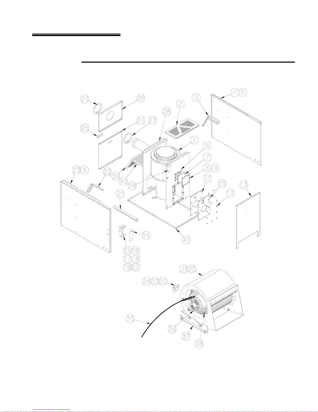
Figure 7 Model TLB Rear flue furnaces – Component locations
B50107A
670-000-005/1010 25
Page 26
THB & TLB Oil Furnaces – Furnace Manual
11 Components and replacement parts (continued)
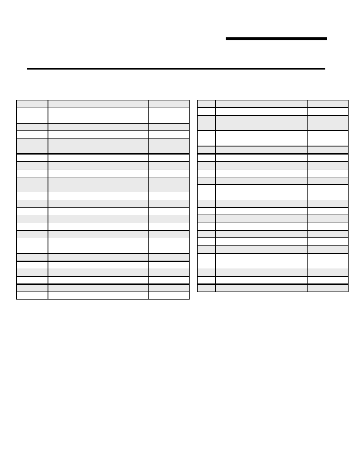
Model TLB Rear flue furnaces – Parts list
Item Part d escr ipti o n Pa rt num be r I tem Par t descr ipti on Part numb er
1
2
3
4
5
6
7
8
9
10
11
12
13
14
15
16
17
18
19
20
21
Com ple t e heat exch anger
(Com bus t ion ch am ber included) Left side pan el assem bl y
Top fro nt pan el B03072 (it em s 5 & 22 included)
Filt er sup port , right B030 73-01 Blower door assem bly
Right side panel asse m bly (item 25 inc luded)
(items 3 & 5 included)
Side panel insulation B03078
Gask et , hea t exchanger B304 15-01
Flange B30487-01
Front divider panel
(item 9 incl uded) Blower as s em bly
Front divider panel insulation B03089 (items 31, 32,33,34, 36 & 37)
Bur ner panel B03071
Bur ner panel gas k et B03105
Hexag onal f lange nut 3/8 -16nc bras s F07O001
Front door B03085
Ele ctric al box cover B02978
Ele ctric al box assembly
( items 16,17,18,19 & 20 include d)
Term inal s t rip, 4 pos itions L05F009 Bell y band assem bly
Trans f orm er 120/ 24 VAC / 40 VA L0 1F 009 (band, legs, nut & bol ts inc luded)
Relay SPDT 24VAC L01H009
Electrical w ire harness (burner) B02915
Electrical w ire harness (fan limit) B02917
Wire conduit B03074
B03037-02
B03087-03
B03090
B02977
Left filter support B03073-02
22
23
24
25
Door handle Z99F05 0
Top rear panel B03069-0 2
26
Ring B10016-06
27
Divid er bac k pan el B03084-02
28
Fan lim it control R02I 002
29
30
Blower 100-10T B 03720-04
31
32
5 MF capac it or L0 1I0 01
Capac it or holder B01024
33
Rubber c ap c apac it or L99Z007
34
35
Electrical w ire harness (blower) B02916
1/3 HP motor wi th leg s B01890-01
36
Blower s upport B03013
37
38
Pap er filter 10" x20" x1" Obtain locally
39
Pap er filter 12" x20" x1" Obtain locally
40
Floor B03082
41
B0308 7-04
B03083
B02584-02
B01888
B50107A
26 670-000-005/1010
Page 27
THB & TLB Oil Furnaces – Furnace Manual
11 Components and replacement parts
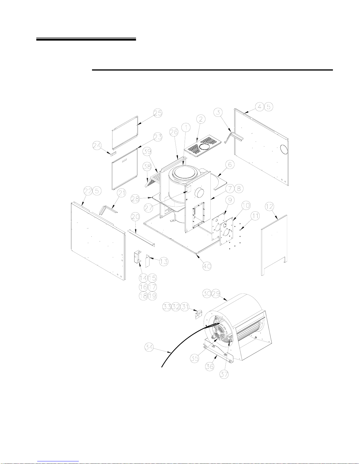
Figure 8 Model TLB Front flue furnaces – Components locations
B50108A
670-000-005/1010 27
Page 28
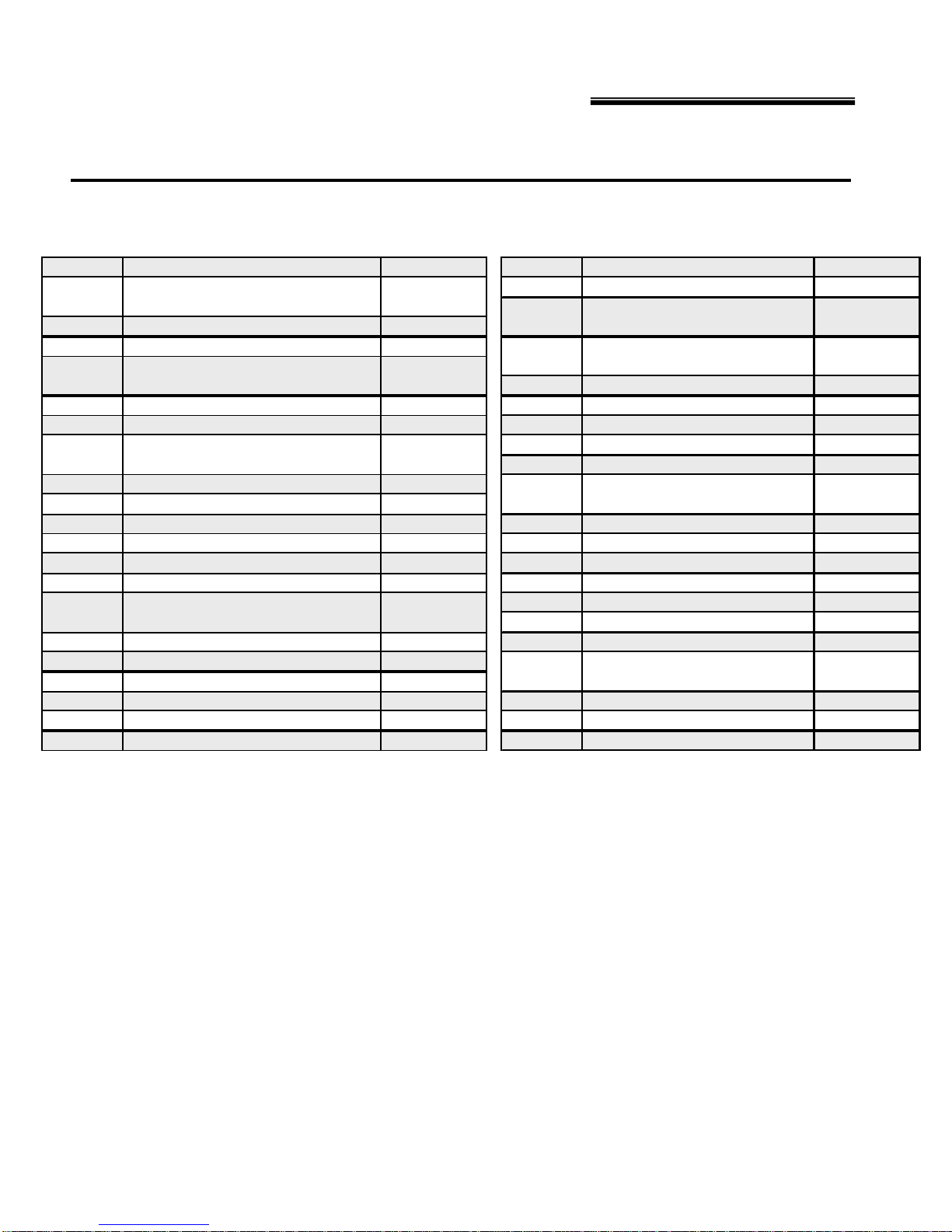
THB & TLB Oil Furnaces – Furnace Manual
11 Components and replacement parts (continued)
Model TLB Front flue furnaces – Part list
Item Part description Part numbe r Item Part description Part num ber
10
11
12
13
14
15
16
17
18
19
20
1
2
3
4
5
6
7
8
9
Com plet e heat exchanger
(Combustion chamber included) Left side panel assembly
Top fro n t pan el B030 57 (item s 5 & 21 included)
Filter support, right B03073-01 Blower door assembly
Right side panel asse m bly (item 24 inc luded )
(item s 3 & 5 included)
Side panel insulation B03078
Baflle, right side B03075-01
Front di vider panel a s s emb ly
(item 8 in cl uded)
Front panel insulation B03086 Blower assembly
Bur ner pan el gas k et B03071 (item s 30, 31, 32,33, 35 & 36)
Bur ner panel B03105
Hexag ona l f lange nut 3/8 - 16nc bras s F07O001
Front door B03085
Electrical box cover B02978
Ele ctric al box assem bly
( ite m s 15,16,17,1 8 & 19 included)
Term inal s t rip, 4 positions L0 5F 009
Trans f orm er 120/24 VAC / 40 VA L01F009 Belly ban d assem bly
Relay SPD T 24VAC L01H009 (ba nd, legs, nut & bolts inc luded)
Ele ctric al wir e harnes s (bur ner) B02915
Ele ctric al wir e harnes s (fan lim it ) B02917
Wire conduit B03074
B03037-01
B03087-01
B03088
B02977
21
22
23
24
25
26
27
28
29
30
31
32
33
34
35
36
37
38
39
40
Left filter support B03073-02
B03087-02
B03083
Door handle Z 99F 050
Top rear panel B03069-01
Div ider bac k panel B030 84-01
Fan lim it con trol R02I 002
Ba ffle, left s ide B03075-02
B02584-02
Blower 100-10T B03720-04
5 MF capac itor L01I001
Capac i t or holder B01024
Rubber cap capacitor L99Z007
El ectrical w ire harnes s (blower) B 02916
1/3 HP motor with legs B01890-01
Blower support B03013
B01888
Pa per fil ter 10" x20"x1 " O btain loc ally
Pa per fil ter 12" x20"x1 " O btain loc ally
Floor B03082
B50108A
28 670-000-005/1010
Page 29
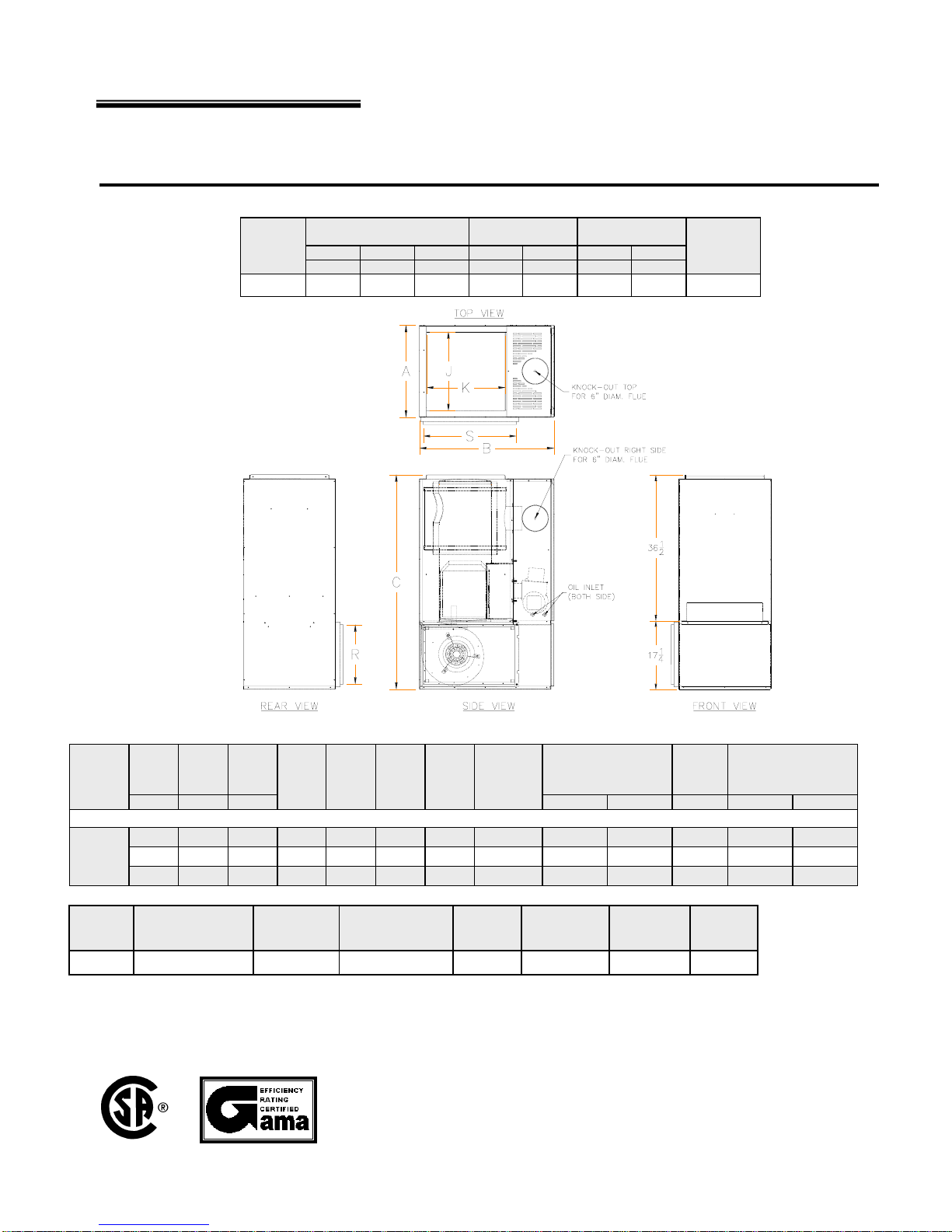
THB & TLB Oil Furnaces – Furnace Manual
12 Dimensions and ratings
Figure 9 Model THB dimensional data – ALL DIMENSIONS IN INCHES
Model
THB-105 23 33 1/2 53 3/4 19 3/4 19 3/4 15 23 6
Furnace casing
Width Depth Height Width Depth Width Depth
ABCJKRS
Warm air supply
(top) Flue pipe
Return air
(side)
diam.
DNS-0906 Rev. B
Model
THB-105
Model Volt - Hertz - Phase
THB-105 65 - 90 1 (16 X 24 X 1) 115 - 60 -1 12.2 13.7 15 210
Input Output
(BTU/h) (BTU/h) (GPH) @ 0.25" W.C. @ 0.50" W.C. (tons) @ 0.25" WC @ 0.50" WC
91,000 77,700 0.65 83.5 81.0 100-10T 1/3 Med. - Low Med. - Low 3 975 925
105,000 87,900 0.75
119,000 98,400 0.85 81.0 80.0 100-10T 1/3 High High 3 1225 1150
Maximum heating Filter Electrical Minimum Maximum Ship
temperature rise quantity load am paci t y f or f use size weight
(oF)
Installed
nozzle
and size
AFUE
¨
with vent
damper
AFUE
Direct-drive un its
82.0 80.5 100-10T 1/3 M ed. - High High 3 1100 1050
Blower
size
Blower motor
HP
(amps)
Blower speed Firing rate
wiring sizing
Maximum
cooling
capacity
(amps) (pounds)
C US
Blower CFM
670-000-005/1010 29
Page 30
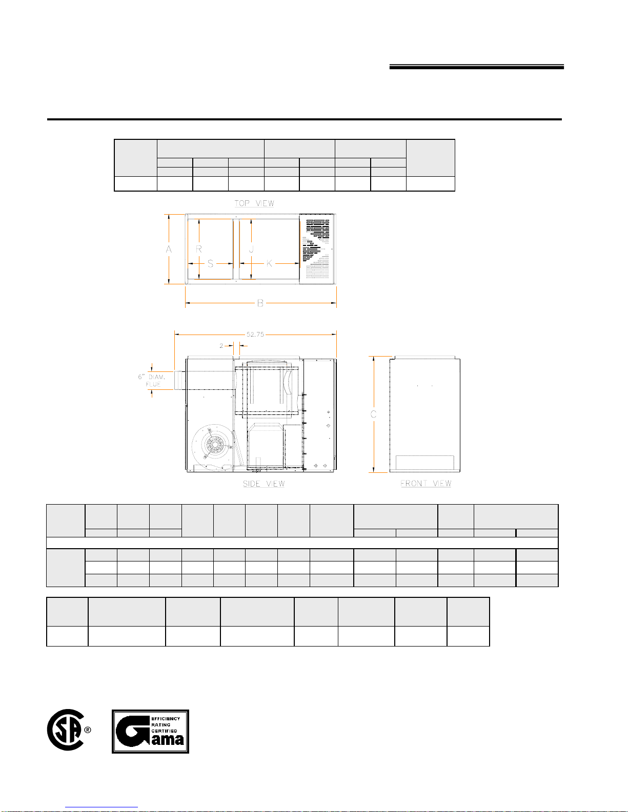
gcap
y
THB & TLB Oil Furnaces – Furnace Manual
12 Dimensions and ratings
Figure 10 Model TLB Rear dimensional data – ALL DIMENSIONS IN INCHES
Model
TLB-105R 23 49 1/4 38 19 3/4 19 3/4 19 3/4 14 3/4 6
Furnace casing
Width Depth Height Width Depth Width Depth
ABCJKRS
Warm air supply
(top)
Return air
(top)
Flue pipe
diam.
DNS-0905 Rev. B
Model
(BTU/h) (BTU/h) (GPH) @ 0.25" W.C. @ 0.50" W.C. (tons) @ 0.25" W.C. @ 0.50" W.C.
91,000 79,100 0.65 83.5 81.0 100-10T 1/3 Med. - Low Med. - Low 3 1050 975
TLB-105R
Model Volt - Hertz - Phase
TLB-10 5R 65 - 90 115 - 60 -1
105,000 90,500 0.75
119,000 101,500 0.85 81.0 80.0 100- 10T 1/3 High H igh 3 1300 1150
Maximum heating Filter Electrical Minimum Maximum Ship
temperature rise quantity load ampacity for fuse size weight
(oF)
Installed
nozzle
an d size
1 (12 X 20 X 1)
1 (10 X 20 X 1)
AFUE
with vent
damper
¨
AFUE
82.0 80.5 100-10T 1/3 Med. - High High 3 1150 1125
Blower
Blower motor
size
Di rect -drive units
(amps)
12.2 13.7 15 225
HP
Blo wer sp eedInput Output Firing rate
wiring sizing
Maximum
coolin
acit
(amp s) (pounds)
Blower CFM
C US
30 670-000-005/1010
Page 31
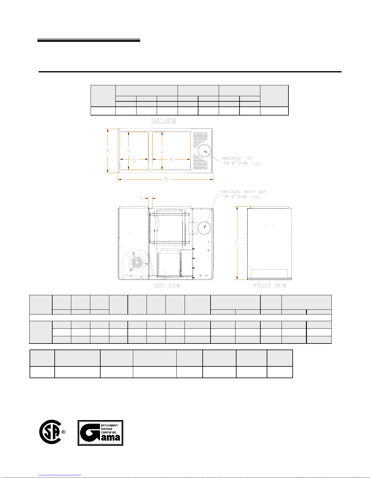
gcap
y
THB & TLB Oil Furnaces – Furnace Manual
12 Dimensions and ratings
Figure 11 Model TLB Front dimensional data – ALL DIMENSIONS IN INCHES
Model
TLB-105F 23 49 1/4 38 19 3/4 19 3/4 19 3/4 14 3/4 6
Furnace casing
Width Depth Height Width Depth Width Depth
ABCJKRS
Warm air supply
(top)
DNS-0904 Rev. B
Model
TLB-105F
Input Output
(BTU/h) (BTU/h) (GPH) @ 0.25" W.C. @ 0.50" W.C. (tons) @ 0.25" W.C. @ 0.50" W.C.
91,000 78,900 0.65 83.5 8 1.0 100-10T 1/3 Med. - Low Med. - Low 3 1050 975
105,000 89,300 0.75
119,000 99,900 0.85 81.0 80.0 100- 10T 1/3 High High 3 1300 1150
Installed
nozzle
AFUE
with vent
damper
82.0 80.5 100-10T 1/3 Med. - High High 3 1150 1125
¨
AFUE
Blower
Blower motor
size
Direct -drive units
HP
Model Volt - Hertz - Phase
TLB-105F 65 - 90 115 - 60 -1 12.2 13.7 15 225
Maximum heating Filter Electrical Minimum Maximum Ship
temperature rise quant i ty load ampacity for fuse size weight
(oF)
and size
1 (12 X 20 X 1)
1 (10 X 20 X 1)
(amps)
wiring sizing
Return air
Blower speedFiring rate
(top)
(amps) (pounds)
Flue pipe
diam.
Maximum
coolin
acit
Blower CFM
C US
670-000-005/1010 31
Page 32
THB & TLB Oil Furnaces – Furnace Manual
12 Dimensions and ratings
Burner data
Model
THB-105 /
TLB-105F/R
Model
THB-105 /
TLB-105F/R
Input
BTU/h
91,000 0.65 0.65-80A 100 F3 NO 3 3/8 0 / 1
105,000 0.75 0.75-80A 100 F3 NO 3 3/8 1 / 3
119,000 0.85 0.85-80A 100 F3 NO 3 3/8 2 / 3
RIELLO BURNER - Model 40-F3 - Tube insertion 6 1/2"
Input Firing rate
BTU/h
91,000 0.65 0.55-60W 140
105,000 0.75 0.60-60W 155
119,000 0.85 0.75-60W 130
BECKETT BURNER - Model AF-F3 (345 0 RPM) - Tube i nsertio n 6 1 /2"
Firing rate
USGPH
Nozzle
(Delavan)
Nozzle
USGPH
(Delavan)
Pump Combustion
pressure air adjustment
Head
(PSIG)
Pump
pressure
(PSIG)
Combustion
air adju s tment
(Turbulator / Band)
2 / 1.25
2 / 2.25
2 / 3.25
Low firing
rate baffle
Stati c disc
(band/shutter)
Model
THB-105 /
TLB-105F/R
CARLIN BURNER - E Z-1 - Tube inserti o n 6 1 /2"
Input
BTU/h
91,000 0.65 0.65-70A 100
105,000 0.75 0.75-70A 100
119,000 0.85 0.85-60A 100
Firing rate
USGPH
Nozzle
(Delavan)
Pump
pressure
(PSIG)
Combustion
air adju s tment
(Bar / Band)
Bar # 0.60-0.65 / 0.60
Bar # 0.75 / 0.75
Bar # 0.85-1.00 / 0.85
32 670-000-005/1010
Page 33
THB & TLB Oil Furnaces – Furnace Manual
12 Dimensions and ratings
Airflow data
Model Blower speed
0.1" 0.2" 0.3" 0.4" 0.5" 0.6" 0.7"
Med-Low 1005 985 965 945 925 905 885
THB-105
TLB-105F
TLB-105R
Notes :
Airflow values in cubic ft per minute (CFM) rounded to nearest 5 CFM.
Data taken with filters in place.
Med-High 1130 1110 1090 1070 1050 1030 1010
High 1270 1240 1210 1180 1150 1120 1090
Med-Low 1095 1065 1035 1005 975 945 915
Med-High 1165 1155 1145 1135 1125 1090 1030
High 1360 1330 1270 1210 1150 1090 1030
Med-Low 1095 1065 1035 1005 975 945 915
Med-High 1165 1155 1145 1135 1125 1090 1030
High 1360 1330 1270 1210 1150 1090 1030
External static pressure
670-000-005/1010 33
Page 34
THB & TLB Oil Furnaces – Furnace Manual
13 Owner’s information
The furnace must be inspected and started ANNUALLY, at the
beginning of the heating season, only by a qualified service technician.
The service technician must perform annual service and maintenance on the furnace to ensure reliable operation.
Failure to service and maintain the furnace and system could result in equipment failure, causing severe personal
W-T Manufacturing
8201 W. Calumet Rd. •Milwaukee, WI 53223
injury, death or substantial property damage.
As the owner, you nee to be aware of the following requirements: You must inspect and clean or replace the
furnace filter monthly, as described below, and perform the other inspection procedures as well. Failure to maintain
a clean filter will result in cycling of the furnace and could lead to a no-heat condition. Failure to perform this
maintenance could result in substantial property damage.
Follow all of the procedures below. Failure to comply could result in severe personal injury, death or substantial
property damage.
Operating the furnace
1. The furnace should operate automatically on call for heat from the room thermostat.
2. If the furnace oil burner should shut down on flame failure, the burner primary control will lock out. Ask your
service technician to show you the correct procedure to reset the primary control button. NEVER push the
button more than once in an attempt to start the burner after lockout. Continued lockout of the control means
something is wrong with the burner, controls or oil system. The condition must be corrected by a qualified
service technician.
Daily inspection
1. Verify there are no combustible materials in the furnace room or near the furnace.
2. Verify the air openings to the furnace room are not obstructed in any way.
3. Verify the furnace seems to be operating normally. Notify your service technician immediately if you notice any
abnormal behavior.
Monthly – inspect and clean/replace filter
1. Ask your service technician to sh ow you the correct way to remove and clean your furnace filter. Replace the
filter if you are unable to thoroughly clean it.
To shut down furnace
1. Set the room thermostat to its lowest setting.
2. Turn off the disconnect switch in the 120-VAC power line to the furnace.
3. If the burner will be shut down for an extended time, tightly close all oil valves.
4. Refer to burner manual for any additional instructions.
34 670-000-005/1010
Page 35

Page 36

THB & TLB Oil Furnaces – Furnace Manual
X40108 Rev. J
 Loading...