


US
Portland
P/N 850,026M REV. E 03/2010
TM
INSTALLATION INSTRUCTIONS
Direct-Vent
MONTEBELLO™
MODELS
OTL Report No. 116-F-22-5
Ce manuel d’installation est disponible en francais, s implement en faire
la demande. Numéro de la pièce 850,026CF.
WARNING
HOT GLASS WILL
CAUSE BURNS.
DO NOT TOUCH GLASS
UNTIL COOLED.
NEVER ALLOW CHILDREN TO
TOUCH GLASS.
This appliance may be installed in an aftermarket permanently located, manufactured home (USA only) or mobile
home, where not prohibited by local codes. This appliance is only for use with the type of gas indicated on the rating
plate. This appliance is not convertible for use with other gases, unless a certified kit is used.
AVERTISSEMENT
Millivolt Models Electronic Models
LSM40MN-2 LSM40EN-2
LSM40MP-2 LSM45EN-2
LSM45MN-2
LSM45MP-2
UNE SURFACE VITR E CHAUDE PEUT
CAUSER DES BR LURES.
LAISSER REFROIDIR LA SURFACE
VITRE AVANT D'Y TOUCHER.
NE PERMETTEZ JAMAIS UN ENFANT
DE TOUCHER LA SURFACE VITRE.
WARNING: If the information in these instructions is
not followed exactly, a fire or explosion may result
causing property damage, personal injury or death.
- Do not store or use gasoline or other flammable vapors and
liquids in the vicinity of this or any other appliance.
- WHAT TO DO IF YOU SMELL GAS
• Do not try to light any appliance.
• Do not touch any electrical switch; do not use any
phone in your building.
• Immediately call your gas supplier from a neighbor’s
phone. Follow the gas supplier’s instructions.
• If you cannot reach your gas supplier, call the fire
department.
- Installation and service must be performed by a quali
fied installer, service agency or the gas supplier.
INSTALLER: Leave this manual with the appliance.
CONSUMER: Retain this manual for future reference.
INSTALLATEUR: Laissez cette notice avec l'appareil.
CONSOMMATEUR
tation ultérieure.
: Conservez cette notice pour consul-
AVERTISSEMENT: Assurez-vous de bien suivre les
instructions données dans cette notice pour réduire
au minimum le risque d’incindie ou d’explosion ou
pour éviter tout dommage matériel, toute blessure
ou la mort.
- Ne pas entreposer ni utilizer d’essence ni d’autres
vapeurs ou liquides inflammables dans le voisinage
de cet appareil ou de tout autre appareil.
- QUE FAIRE SI VOUS SENTEZ UNE ODEUR DE GAZ:
• Ne pas tenter d’allumer d’appareil.
• Ne touchez à aucan interrupteur. Ne pas vous servir
des téléphones se trouvant dans le bâtiment où vous
-
trouvez.
• Appelez immédiatement votre fournisseur de gaz
depuis un voisin. Suivez les instructions du fournisseur.
• Si vous ne pouvez rejoindre le fournisseur de gaz,
appelez le service des incindies.
- L’installation et l’entretien doivent être assurés par un
installateur ou un service d’entretien qualifié ou par
le fournisseur de gaz.
TABLE OF CONTENTS
PACKAGING
GENERAL INFORMATION
Packaging .........................................Page 2
Introduction ......................................Page 2
General Information
Massachusetts and New York
Requirements
Cold Climate Insulation
Manufactured Home Requirements
Location ............................................Page 5
Vent Termination Clearances
Minimum Clearances to Combustibles
Detailed Installation Steps
Typical Installation Sequence
Step 1. Framing
Fireplace and Framing Specifications
Step 2. Routing Gas Line
Proper Sizing of Gas Line
Step 3. Install the Vent System
Vertical Termination Systems
Vent Section Length Chart
Vertical Vent Tables and Figures
Horizontal Termination System
Horizontal Vent Tables and Figures
Step 4. Field Wiring
Step 5. Removing Glass Door
Frame Assembly
Step 6. Connecting Gas Line
Step 7. Checking Appliance
Operation
Step 8. Installing Logs and Panels
Step 9. Installing Glass Door
Step 10. Burner Adjustments
Finishing Requirements
Step 11. Attaching Safety in
Operation Warnings ............... Page 29
Installation Accessories
Gas Conversion Kits .................. Page 31
This manual is part of a set of two supporting
this product. Refer to manual 875,027M for
Care and Operation information.
..........................Page 2
................................Page 4
.....................Page 5
..Page 5
............Page 6
Page 8
.................Page 9
...........Page 9
...............................Page 9
..Page 10
................Page 11
..................Page 11
.......Page 12
............Page 13
................Page 13
........Page 16
.........Page 17
...Page 19
.........................Page 21
...........................Page 22
...........Page 22
......................................Page 23
..Page 24
..........Page 26
............Page 26
....................Page 28
....................Page 30
Please read and understand these
instructions before beginning your
installation.
The assembled vented gas fireplace is packaged with:
1 - one envelope located in the firebox contain
ing the literature package, which consists of
the care and operation manual, installation
instructions, safety in operation warning
labels and warranty
2- one bag of glowing embers and volcanic
stone
3 - one of the following brick liner kits:
a. Brick Liner Kit, Rustic
b. Brick Liner Kit, Herringbone
c. Brick Liner Kit, Old Cottage
d. Brick Liner Kit, Black.
e. Brick Liner Kit, Red Rustic
f. Brick Liner Kit, Red Herringbone
4 - one of the following log sets:
a. Birch Log set
b. Oak Log set
5 - pull screen
6 - door modesty shield
INTRODUCTION
The Millivolt appliances are designed to operate
on natural or propane gas and have a millivolt
gas control valve with piezo ignition system.
The
Electronic appliances are designed to
operate on natural or propane gas and have a
electronic intermittent pilot ignition system. No
external electrical power is required to operate
these units.
These vented gas fireplaces are sealed com
bustion gas fireplaces designed for residential
applications.
Use Only These Approved Vent Components
- These fireplaces are designed, tested and
listed for operation and installation with,
the following (8" inner and 11" outer) vent
components only:
•
Secure Vent™ Direct Vent System Components manufactured by Security Chimneys
International.
These approved vent system components are
labeled for identification. DO NOT use any
other manufacturer’s vent components with
these appliances.
WARNING
Young children should be care-
-
fully supervised when they are
in the same room as the appliance. Toddlers, young children
and others may be susceptible
to accidental contact burns. A
physical barrier is recommended
if there are at risk individuals in
the house. To restrict access to
a fireplace or stove, install an
adjustable safety gate to keep
toddlers, young children and
other at risk individuals out of
the room and away from hot
surfaces.
AVERTISSEMENT
Les jeunes enfants devraient être
surveillés étroitement lorsqu’ils
se trouvent dans la même pièce
que l’appareil. Les tout petits,
les jeunes enfants ou les adultes
peuvent subir des brûlures s’ils
viennent en contact avec la surface chaude. Il est recommandé
d’installer une barrière physique
si des personnes à risques habitent la maison. Pour empêcher
l’accès à un foyer ou à un poêle,
-
installez une barrière de sécurité; cette mesure empêchera les
tout petits, les jeunes enfants et
toute autre personne à risque
d’avoir accès à la pièce et aux
surfaces chaudes.
Children and adults should be alerted to the
hazards of high surface temperature and
should stay away to avoid burns or clothing
ignition.
Les enfants et les adultes devraient être informés des dangers que posent les températures
de surface élevées et se tenir à distance afin
d’éviter des brûlures ou que leurs vêtements
ne s’enflamment.
DO NOT ATTEMPT TO ALTER OR MODIFY
THE CONSTRUCTION OF THE APPLIANCE OR
2
ITS COMPONENTS. ANY MODIFICATION OR
ALTERATION MAY VOID THE WARRANTY,
CERTIFICATION AND LISTINGS OF THIS
UNIT.
WARNING
Improper installation, adjustment, alteration, service or
maintenance can cause injury
or property damage. Refer to
this manual. For assistance or
additional information consult
a qualified installer, service
agency or the gas supplier.
WARNING
Failure to comply with these
installation instructions will result
in an improperly installed and
operating appliance, voiding its
warranty. Any change to this appliance and/or its operating controls
is dangerous.
WARNING
Clothing or other flammable
material should not be placed
on or near the appliance.
AVERTISSEMENT
On ne devrait pas placer de
vêtements ni d’autres matières
inflammables sur l’appareil ni à
proximité.
WARNING
Any safety screen or guard
removed for servicing the appliance must be replaced prior to
operating the appliance.
AVERTISSEMENT
Tout écran ou protecteur retiré
pour permettre l’entretien de
l’appareil doit être remis en
place avant de mettre l’appareil
en marche.
WARNING
Improper installation or use of
this appliance can cause serious
injury or death from fire, burns,
explosion or carbon monoxide
poisoning.
Note: Installation and repair should be done
by a qualified service person. The appliance
should be inspected before use and at least
annually by a professional service person.
More frequent cleaning may be required
due to excessive lint from carpeting, bedding material, etcetera. It is imperative
that control compartments, burners and
circulating air passageways of the appliance
be kept clean.
Remarque : L’installation et la réparation
devrait être confiées à un technicien qualifié.
L’appareil devrait faire l’objet d’une inspection par un technicien professionnel avant
d’être utilisé et au moins une fois l’an par la
suite. Des nettoyages plus fréquents peuvent
être nécessaires si les tapis, la literie, et
cetera produisent une quantité importante de
pous-sière. Il est essentiel que les compartiments abritant les commandes, les brûleurs et
les conduits de circulation d’air de l’appareil
soient tenus propres.
Do not use these appliances if any part
has been under water. Immediately call a
qualified, professional service technician
to inspect the appliance and to replace any
parts of the control system and any gas
control which have been under water.
Ne pas se servir de cet appareil s'il a été
plongé dans l'eau, complètement ou en
partie. Appeler un technicien qualifié pour
inspecter l'appareil et remplacer toute partie
du système de contrôle et toute commande
qui ont été plongés dans l'eau.
Only trim kit(s) supplied by the manufacturer
shall be used in the installation of this appliance.
Seules les trousses de garniture fournies
par le fabricant doivent être utilisées pour
l’installation de cet appareil.
These appliances comply with National Safety
Standards and are tested and listed by OMNITest Laboratories, Inc. (Report No. 116-F-22-5)
to ANSI Z21.50 (in Canada, CSA-2.22), and
CAN/CGA-2.17-M91 in both USA and Canada,
as vented gas fireplaces.
Both millivolt and electronic versions of
these appliances are listed by OMNI-Test
Laboratories for installation in bedrooms and
mobile homes.
Misc. Codes / Standards -
The Installation must conform to local codes.
In the absence of local codes, installation must
comply with the current
ANSI Z223.1. (In Canada, the current CAN/CSA-
B149.1 installation code).
National Fuel Gas Code,
The appliance, when installed, must be electrically grounded in accordance with local codes or,
in the absence of local codes, with the
Electrical Code, ANSI/NFPA 70 - latest edition,
or the
Canadian Electrical Code, CSA C22.1
- latest edition.
Provide adequate clearances around air open
ings and adequate accessibility clearance for
service and proper operation. Never obstruct
the front openings of the appliance.
These appliances are designed to operate on
natural or propane gas only. The use of other
fuels or combination of fuels will degrade
the performance of this system and may be
dangerous.
These fireplaces are designed as supplemental
heaters. Therefore, it is advisable to have an
alternate primary heat source when installed
in a dwelling.
Millivolt Models - The millivolt appliances are
manually controlled and feature a spark igniter
(piezo) that allows the appliance's pilot gas to be
lit without the use of matches or batteries. This
system provides continued service in the event
of a power outage.
The Millivolt models come standard with the
manually-modulated gas valve; flame appear
ance and heat output can be controlled at the
gas valve. The BTU Input for these appliances
is shown in
Electronic Models - The electronic appliances are manually controlled and feature an
electronic intermittent pilot ignition system.
External electrical power is required to operate
these units.
Electronic models come standard with a manu
ally-modulated gas valve; flame appearance
and heat output can be controlled at the gas
valve. The BTU Input for these appliances is
shown in
Table 1.
Table 1.
Input (BTU/HR) - All Models
Model No. Input (BTU/Hr)
Natural Gas
LSM40-2 40,000 to 50,000
LSM45-2 47,000 to 60,000
Propane Gas
LSM40-2 40,000 to 50,000
LSM45-2 48,000 to 60,000
National
Table 1
-
-
-
3
H
I
L
O
W
TPTH TP TH
P
I
L
O
T
P
I
L
O
T
O
N
it
O
F
F
Hi / Lo
Variable Flame
Height Adjustment
Manifold
Pressure
Gauge Port
Inlet Pressure
Gauge Port
Main Gas
Control Knob
Off / Pilot / On
Pilot
Adjustment
Screw
IN
OUT
Gas Supply Inlet
Gas Outlet to Burner
Gas Pressure - All Models
HI
LO
Tables 2 and 3 show the appliances' inlet and
manifold gas pressure requirements:
4
Inlet Gas Supply Pressure
(all models)
Fuel # Minimum Maximum
Natural Gas
Propane
5.5" WC
(1.37 kPa)
11.0" WC
(2.74 kPa)
10.5" WC
(2.61 kPa)
13.0" WC
(3.23 kPa)
Table 2
Manifold Gas Supply Pressure
(all models)
Fuel # Low High
Natural
Gas
Propane
(Lo) 2.2" WC
(.55 kPa)
(Lo) 6.3" WC
(1.57 kPa)
(Hi) 3.5" WC
(.87 kPa)
(Hi) 10.0" WC
(2.49 kPa)
Table 3
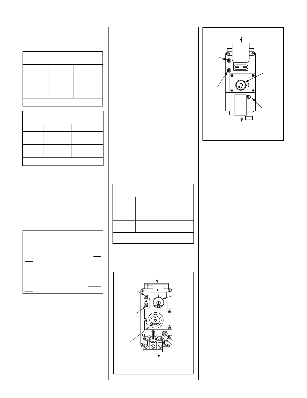
Test gauge connections are provided on the
front of the millivolt and electronic gas control
valve (identified IN for the inlet and OUT for the
manifold side).
Propane tanks are at pressures that will cause
damage to valve components. Verify that the
tanks have step down regulators to reduce the
pressure to safe levels.
These appliances must be isolated from the
gas supply piping system (by closing their
individual manual shut-off valve) during any
pressure testing of the gas supply piping
system at test pressures equal to or
than 1/2 psig (3.5 kPa).
These appliances and their individual shut-off
valves must be disconnected from the gas
supply piping system during any pressure
testing of that system at pressures
than 1/2 psig (3.5 kPa).
These appliances must not be connected to a
chimney or flue serving a separate solid fuel
burning appliance.
less
greater
Orifice Sizes - Sea Level To High Altitude
(All Models)
These appliances are tested and approved for
installation at elevations of 0-4500 feet (0-1372
meters) above sea level, using the standard
burner orifice sizes (marked with an "*" in Table
4). For elevations above 4500 feet, contact your
gas supplier or qualified service technician.
Deration - At higher elevations, the amount
of BTU fuel value delivered must be reduced
by either:
• Using gas that has been derated by the gas
company.
• Changing the burner orifice to a smaller size
as regulated by the local authorities having
jurisdiction and by the (USA) National Fuel
Gas Code NFPA 54/ANSI Z223.1 - latest
edition or, in Canada, the CAN/CSA-B149.1
codes - latest edition.
Install the appliance according to the regulations
of the local authorities having jurisdiction and,
in the USA, the National Fuel Gas Code NFPA
54 / ANSI Z223.1 - latest edition or , in Canada,
the CAN/CSA-B149.1- latest edition.
NOTE: Flame appearance will diminish 4% per
thousand feet.
Burner Orifice Sizes
Elevation 0-4500 feet ( 0-1372 meters)
Model Nat.Gas
drill size (inches)
LSM40-2 .1405" (#28)*
• H2286
LSM45-2 .161" (#20)*
• H2288
Table 4
* Standard size installed at factory
• Part /Cat. Number
Propane
drill size (inches)
.086" (#44)*
• H2287
.093" (#42)*
• H4816
Gas Valve Diagrams
See
Figure 1 for Millivolt models and Figure 2
For Electronic Models.
Figure 1 - SIT Millivolt Gas Valve
NOTE: DIAGRAMS & ILLUSTRATIONS ARE NOT TO SCALE.
Gas Supply Inlet
Inlet Pressure
Gauge Port
Manifold
Pressure
Gauge Port
Gas Outlet to Burner
Hi / Lo
Variable Flame
Height
Adjustment
Pilot
Adjustment
Screw
Figure 2 - SIT Electronic Gas Valve
REQUIREMENTS FOR THE COMMONWEALTH OF MASSACHUSETTS
These fireplaces are approved for installation in
the US state of Massachusetts if the following
additional requirements are met:
• Install this appliance in accordance with
Massachusetts Rules and Regulations 248
C.M.R.
• Installation and repair must be done by a
plumber or gas fitter licensed in the Com
monwealth of Massachusetts.
• The flexible gas line connector used shall
not exceed 36 inches (92 centimeters) in
length.
• The individual manual shut-off must be a
T-handle type valve.
Massachusetts Horizontal Vent Requirements
In the Commonwealth of Massachusetts,
horizontal terminations installed less than
seven (7) feet above the finished grade
must comply with the following additional
requirements:
• A hard wired carbon monoxide detector
with an alarm and battery back-up must be
installed on the floor level where the gas
fireplace is installed. The carbon monoxide
detector must comply with NFPA 720, be
ANSI/UL 2034 listed and be ISA certified.
• A metal or plastic identification plate must
be permanently mounted to the exterior of
the building at a minimum height of eight (8)
feet above grade and be directly in line with
the horizontal termination. The sign must
read, in print size no less than one-half (1/2)
inch in size, GAS VENT DIRECTLY BELOW.
KEEP CLEAR OF ALL OBSTRUCTIONS.
NEW YORK CITY, NEW YORK (MEA)
Installation of these fireplaces are approved for
installation in New York City in the US state
of New York.
-
Dr
ywall
T
op Of Firepl
ace
Opening
Non-Combus
tible
HORIZONTAL VENT
VERTICAL VENT
HORIZONTAL VENT
VERTICAL VENT
COLD CLIMATE INSULATION
For cold climate installations, seal all cracks
around your appliance with noncombustible
material and wherever cold air could enter
the room. It is especially important to insulate
outside chase cavity between studs and under
floor on which appliance rests, if floor is above
ground level. Gas line holes and other openings should be caulked or stuffed with unfaced
fiberglass insulation.
If the fireplace is being instal
slab in cold climates, a sheet
led on a cement
of plywood or
other raised platform can be placed underneath
to prevent cold transfer to the fireplace and
the room.
It also helps to sheetrock inside
into
surfaces and tape for maximum air tightness
and caulk firestops.
MANUFACTURED HOME
REQUIREMENTS
Cross Corner
Application
Room Divider
Application
Recessed
Application
Island
Application
Flat
Application
Application
Flat on Wall
This appliance may be installed in an aftermarket permanently located, manufactured home
and must be installed in accordance with the
manufacturer's instructions and the Manufac
tured Home Construction and Safety Standard,
Title 24 CFR, Part 3280, in the United States, or
the Standard for Installation in Mobile Homes,
CAN/CSA Z240 MH Series, in Canada.
Cet appareil peut être installé cómme du matériel d'origine dans une maison préfabriquée (É.U.
seulement) ou mobile et doit être installé selon
les instructions du fabricant et conformément
à la norme Manufactured Home Constructions
and Safety, Title 24 CFR, Part 3200 aux Unis ou
à la norme Can/CSA-Z240 Série MM, Maisons
mobiles au Canada.
This appliance is only for use with the type of gas
indicated on the rating plate. This appliance is
not convertible for use with other gases, unless
a certified kit is used.
Cet appareil doit être utilisé uniquement avec le
type de gaz indiqué sur la plaque signalétique.
Cet appareil ne peut être converti à d'autres gaz,
sauf si une trousse de conversion est utilisée.
CAUTION: Ensure that the cross members
are not cut or weakened during installation.
The structural integrity of the manufactured
home floor, wall, and ceiling / roof must be
maintained.
CAUTION: This appliance must be grounded
to the chassis of the manufactured home in
accordance with local codes or in the absence
of local codes, with the National Electrical
Code ANSI / NFPA 70 - latest edition or the
Canadian Electrical Code CSA C22.1 - latest
edition.
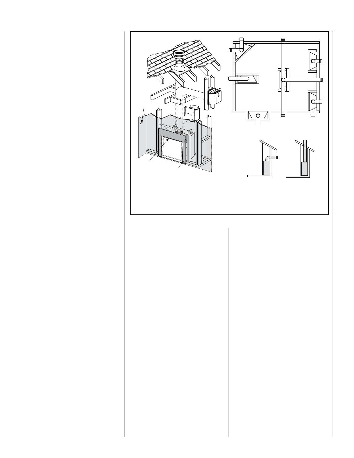
When the unit is installed with one side flush with a wall,
the wall on the other side of the unit must not extend
beyond the front edge of the unit.
-
Figure 3 - Typical Installation
LOCATION
In selecting the location, the aesthetic and
functional use of the appliance are primary
concerns. However, vent system routing to
the exterior and access to the fuel supply are
also important.
Due to high temperatures, the appliance
should be located out of traffic and away from
furniture and draperies (Figure 3).
En raison des températures élevées, l’appareil
devrait être installé dans un endroit où il y a
peu de circulation et loin du mobilier et des
tentures (Figure 3).
The location should also be free of electrical,
plumbing or other heating/air conditioning
ducting.
These direct-vent appliances are uniquely
suited for installations requiring a utility shelf
positioned directly above the fireplace. Utility
shelves like these are commonly used for locating television sets and decorative plants.
NOTE: DIAGRAMS & ILLUSTRATIONS ARE NOT TO SCALE.
Be aware that this is a heat producing appliance. Objects placed above the unit are
exposed to elevated temperatures.
Do not insulate the space between the appliance and the area above it (see Figure 8
on Page 8).
The minimum height from the base of the appli
ance to the underside of combustible materials
used to construct a utility shelf in this fashion
is shown in
Figure 8 on Page 8.
The appliance should be mounted on a fully
supported base extending the full width and
depth of the unit. The appliance may be located
on or near conventional construction materials.
However, if installed on combustible materials,
such as carpeting, vinyl tile, etc., a metal or
wood barrier covering the entire bottom surface
must be used.
-
5
3"
(76 mm)
Termination Kit
Combustible Projection
greater than 2-1/2 inches in length
Horizontal Vent Termination Clearances
Combustible Projection
2-1/2 inches or less in length
24"
(610 mm)
Ventilated Or
Unventilated Soffit
12
X
Roof Pitch is X/12
2 FT
MIN.
2 FT MIN.
Lowest
Discharge
Opening
H*
*H = MINIMUM HEIGHT FROM ROOF TO
LOWEST DISCHARGE OPENING OF VENT
TERMINATION HEIGHTS FOR VENTS ABOVE
FLAT OR SLOPED ROOFS
Horizontal Overhang
Vertical
Wall
Vent
Termination
Storm Collar
Concentric
Vent Pipe
Flashing
1 inch (25.4 mm) Minimum
Clearance to Combustibles
VENT TERMINATION CLEARANCES
These instructions should be used as a
guideline and do not supersede local codes
in any way. Install vent according to local
codes, these instructions, the current National
Fuel Gas Code (ANSI-Z223.1) in the USA or
the current standards of CAN/CSA-B149.1 in
Canada.
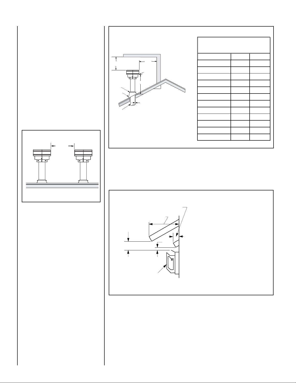
Vertical Vent Termination Clearances
Terminate multiple vent terminations according
to the installation codes listed above. Also see
Figure 4.
Terminate single vent caps relative to building
components according to
Figure 5.
12”
(305mm)
Minimum
Vertical Vent Termination Clearances
The vent / air intake termination clearances
above the high side of an angled roof is as
shown in the following chart:
Figure 5
Horizontal Vent Termination Clearances
Termination Heights For Vents
Above Flat Or Sloped Roofs
Ref. NFPA 54 / ANSI Z223.1
Roof Pitch * Feet * Meters
Flat to 6/12
6/12 to 7/12
7/12 to 8/12
8/12 to 9/12
9/12 to 10/12
10/12 to 11/12
11/12 to 12/12
12/12 to 14/12
14/12 to 16/12
16/12 to 18/12
18/12 to 20/12
20/12 to 21/12
1.0 0.3
1.25 0.38
1.5 0.46
2.0 0.61
2.5 0.76
3.25 0.99
4.0 1.22
5.0 1.52
6.0 1.83
7.0 2.13
7.5 2.29
8.0 2.44
Figure 4 - Multiple Terminations
6
The horizontal vent termination must have a minimum of 3" (76 mm) clearance to any overhead
combustible projection of 2-1/2" (64 mm) or less (see
(64 mm), see
Figure 7. For additional vent location restrictions refer to Figure 7 on Page 7.
Figure 6). For projections exceeding 2-1/2"
See Figure 30 on Page 18 for the recess allowances, into
exterior walls, of the square horizontal terminations.
Figure 6 - Side Elevation View
NOTE: DIAGRAMS & ILLUSTRATIONS ARE NOT TO SCALE.
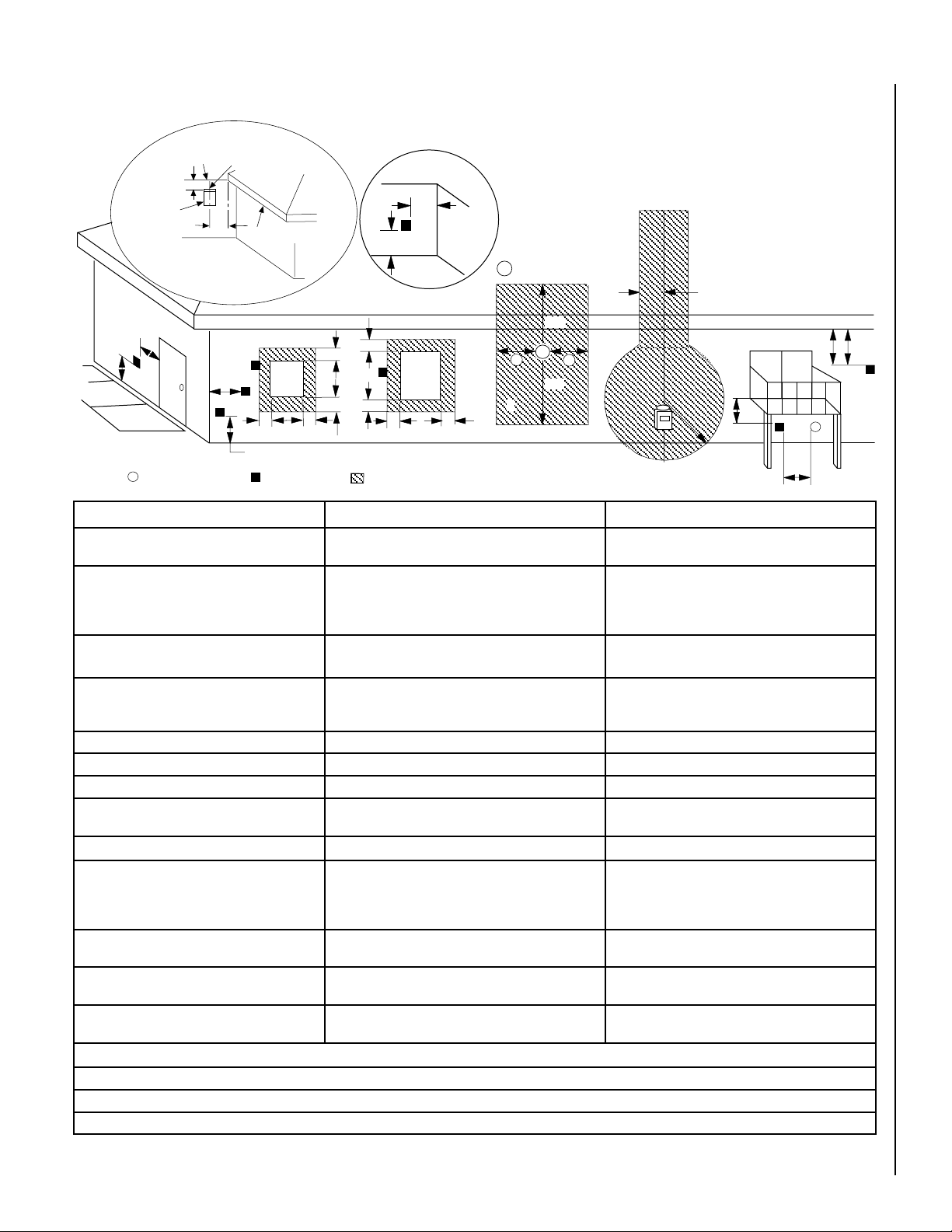
EXTERIOR HORIZONTAL VENT TERMINATION CLEARANCE REQUIREMENTS
V
V
V
V
V
F
C
B
B
A
B
H
M
I
X
V
D
V
A
A
A
V
L
B
J
X
E
V
A
G
*18”
18”
B
C
C
C
K
X
�
�
�
* See Item D in the Text Below.
Exterior Wall
24"
Horizontal
Termination
Inside Corner
= Air Supply Inlet
Center Line
of Termination
36"
DETAIL D
Ventilated Soffit
Fixed
Closed
Window
= Vent Terminal
Inside
Corner Detail
= 9" in U.S.
= 12" in Canada
Operable
Window
= Area where Terminal is NOT permitted
NOTE: Local Codes Or Regulations May Require
Different Clearances.
NOTE: Location Of The Vent Termination Must Not
Interfere With Access To The Electrical Service.
3 ft.
3 ft.
Minimum Clearances Canadian Installation * US Installation **
A = Clearance above grade, veranda, porch, deck
or balcony.
B = Clearance to window or door that may be
opened.
C = Clearance to permanently closed window 12 inches (305 mm) recommended to prevent window
12 inches (30 cm) * 12 inches (30 cm) **
6 in. (15.2 cm) for appliances < 10,000 BTU/hr (3kW),
12 in. (30 cm) for appliances > 10,000 BTU/hr (3kW) and <
100,000 BTU/hr (30kW), 36 inches (91 cm) for appliances
> 100,000 BTU/hr (30kW)*
condensation
6 in. (15.2 cm) for appliances < 10,000 BTU/hr (3kW),
9 in. (23 cm) for appliances > 10,000 BTU/hr (3kW) and <
50,000 BTU/hr (15kW), 12 inches (30 cm) for appliances
> 50,000 BTU/hr (15kW)*
9 inches (229 mm) recommended to prevent window
condensation
D = Vertical clearance to ventilated soffit located
24 inches (61.0 cm) 24 inches (61.0 cm)
above the terminal within a horizontal distance of 36
in. (91.4cm) from the center line of the terminal
E = Clearance to unventilated soffit 24 inches (61.0 cm) 24 inches (61.0 cm)
F = Clearance to outside corner 5 inches (12.7 cm) 5 inches (12.7 cm)
G = Clearance to inside corner 36" (91.4 cm) 24 inches (61.0 cm)
H = Clearance to each inside of center line extended
above meter / regulator assembly
3 feet (91 cm) within a height of 15 feet above the meter /
regulator assembly *
3 feet (91 cm) within a height of 15 feet above the meter
/ regulator assembly **
I = Clearance to service regulator vent outlet 3 feet (91 cm) * 3 feet (91 cm) **
J = Clearance to non-mechanical air supply inlet
to building or the combustion air inlet to any other
appliance
K = Clearance to mechanical air supply inlet 6 feet (1.83 meters) * 3 feet (91 cm) above, if within 10 feet (3 m) horizon
L = Clearance above paved sidewalk or paved
driveway located on public property
M = Clearance under veranda, porch, deck or
balcony
6 in. (15.2 cm) for appliances < 10,000 BTU/hr (3kW), 12
in. (30 cm) for appliances > 10,000 BTU/hr (3kW) and <
100,000 BTU/hr (30kW), 36 inches (91 cm) for appliances
> 100,000 BTU/hr (30kW)*
7 feet (2.13 m) ‡ 7 feet (2.13 m) ‡
18 in. (46.0 cm) * ‡ 18 in. (46.0 cm) ** ‡
6 in. (15.2 cm) for appliances < 10,000 BTU/hr (3kW), 9
in. (23 cm) for appliances > 10,000 BTU/hr (3kW) and <
50,000 BTU/hr (15kW), 12 inches (30 cm) for appliances
> 50,000 BTU/hr (15kW)*
tally**
* In accordance with the current CSA-B149.1 National Gas and B149.2 Propane Installation Code - Latest Editions.
** In accordance with the current ANSI Z223.1 / NFPA 54 National Fuel Codes - Latest Edition.
‡ A vent shall not terminate directly above a sidewalk or paved driveway which is located between two single family dwellings and serves both dwellings.
*‡ Only permitted if veranda, porch, deck or balcony is fully open on a minimum 2 sides beneath the floor.
Figure 7
NOTE: DIAGRAMS & ILLUSTRATIONS ARE NOT TO SCALE.
-
7

MINIMUM CLEARANCES TO COMBUSTIBLES
17"
14"
8-1/4”
45°
12"
5"
12 (305)
10 (254)
8 (203)
6 (152)
4 (102)
7
(178)
17
(432)
15
(381)
13
(330)
2 (51)
9
(229)
11
(279)
The appliance is approved with zero clearance to combustible materials on
all sides (as detailed in
unit is installed with one side flush with a wall, the wall on the other
side of the unit must not extend beyond the front edge of the unit. In
addition, when the unit is recessed, the side walls surrounding the unit
must not extend beyond the front edge of the unit (see
Table 5), with the following exception: When the
Figure 3).
Combustible Shelf Height -
Top Vent - with 2 Feet Vertical Vent and One 90 Degree Elbow
Model Secure Vent
LSM40-2 *84-1/16 (2135)
LSM45-2 89-1/16 (2252)
* Includes 3” clearance to combustibles (required above vent components)
Inches (millimeters)
APPLIANCE MINIMUM CLEARANCES*
Inches (millimeters)
Sides 1/2 (13), 0 (0) Spacers **
Top Spacers 0 (0)
Floor 0 (0)
Back 1/2 (13), 0 (0) Spacers
Bottom of Appliance To Ceiling 69 (1743)
Vent 3 (76) Top* / 1 (25.4) Sides & Bottom
SERVICE CLEARANCES Feet (meters)
Front 3 feet (0.9 meters)
Table 5
*Note: 3 in. (75 mm) above any horizontal/inclined vent component.
**Note: See Page 9, Step 1 for clearance requirements to the nailing
flange located at each side of the unit and any screw heads adjacent
to it.
The appliance should be mounted on a fully supported base extending
the full width and depth of the unit. The appliance may be located on
or near conventional construction materials. However, if installed on
combustible materials, such as carpeting, vinyl tile, etc., a metal or wood
barrier covering the entire bottom surface must be used.
Shelf Height
To provide for the lowest possible shelf surface, the venting attached to
the top vent should be routed in a way to minimize obstructions to the
space above the appliance. Do not insulate the space between the ap
pliance and the area above it (see
Figure 8). The minimum height from
the base of the appliance to the underside of combustible materials used
to construct a utility shelf in this fashion is shown in
Figure 8.
Wall Finishes / Surrounds / Mantels
Do not insulate the
space between the
appliance and the
area above it.
2 Foot Vertical
Vent (Min.)
MANTEL
CLEARANCES
Inches (mm)
MANTEL
Fireplace
(side view)
Figure 8
Shelf Height
(see table)
Shelf Above Fireplace With Top Venting
MANTEL
MANTEL
MANTEL
MANTEL
MANTEL
Top of Appliance
Figure 9
-
Combustible Materials
Allowed In Shaded Area
"Safe Zone"
Top View of
Fireplace
Note: Combustible wall finish materials and/or surround materials must
not be allowed to encroach the area defined by the appliance front face
(black sheet metal). Never allow combustible materials to be positioned
in front of or overlapping the appliance face. See Figure 10 and Figure
53 on Page 28.
Non-combustible materials, such as surrounds and other appliance trim,
may be installed on the appliance front face with these exceptions: they
must not cover any portion of the removable glass panel.
Vertical installation clearances to combustible mantels vary according
to the depth of the mantel. See
combustible materials may be installed at any height above the appliance
opening.
NOTE: We recommend the use of high temperature paint (rated 175° F
or higher) on the underside of the mantel.
8
Figure 9. Mantels constructed of non-
NOTE: DIAGRAMS & ILLUSTRATIONS ARE NOT TO SCALE.
Figure 10
Side
Wall
Minimum Distance to
Protected Side Wall
Side
Wall
Minimum Distance to
Unprotected Side Wall
Use T
op Flange For
1/2” Thick Dr
ywal
l
Use Bottom Flange Fo
r
5/8” Thick Dr
ywal
l
Front Of
Fireplace
Use Center Flange
For Flush Mount
WARNING
Failure to position the parts in
accordance with these diagrams
or failure to use only parts specifically approved with this appliance
may result in property damage or
personal injury.
AVERTISSEMENT
Risque de dommages ou de
blessures si les pièces ne sont
pas installées conformément à
ces schémas et ou si des pièces
autres que celles spécifiquement
approuvées avec cet appareil sont
utilisées.
DETAILED INSTALLATION STEPS
The appliance is shipped with all gas controls
and components installed and pre-wired.
1. Remove the shipping carton, exposing the
front glass door on the valve access side.
2. Using a Phillips screwdriver, unfasten two (2)
screws located at the top of the glass frame
(see Figure 49). Tilt the top of the glass frame
away from the unit. Lift it carefully off the
bottom door track and set the door aside,
protecting it from inadvertent damage.
TYPICAL INSTALLATION SEQUENCE
Step 3. (Page 12) Install the vent system and
exterior termination.
Step 4. (Page 21) Field Wiring
a. Millivolt and Electronic Appliances
– The operating control switch is factory installed.
b. Electronic Appliances – Connect 120
Vac electrical power to the appliance
receptacle.
Step 5. (Page 22) Remove glass door assem-
bly.
Step 6. (Page 22) Make connection to gas
supply.
Step 7. (Page 23) Verifying appliance opera-
tion.
Step 8. (Page 24) Install ceramic panels, logs
and glowing embers.
Step 9.
Step 10.
Step 11. (Page 29) Attach Safety in Operation
(Page 26) Install glass door assembly.
(Page 26) Adjust burner to ensure
proper flame appearance.
Warnings.
Step 1. FRAMING
Frame these appliances as illustrated in Figure
12 on Page 10, unless the appliance is to be
installed in a corner
11 for corner framing installations. All framing
details must allow for a minimum clearance to
combustible framing members as shown in
Table 5 on Page 8.
If the appliance is to be elevated above floor
level, a solid continuous platform must be
constructed below the appliance.
. See Figure 13 on Page
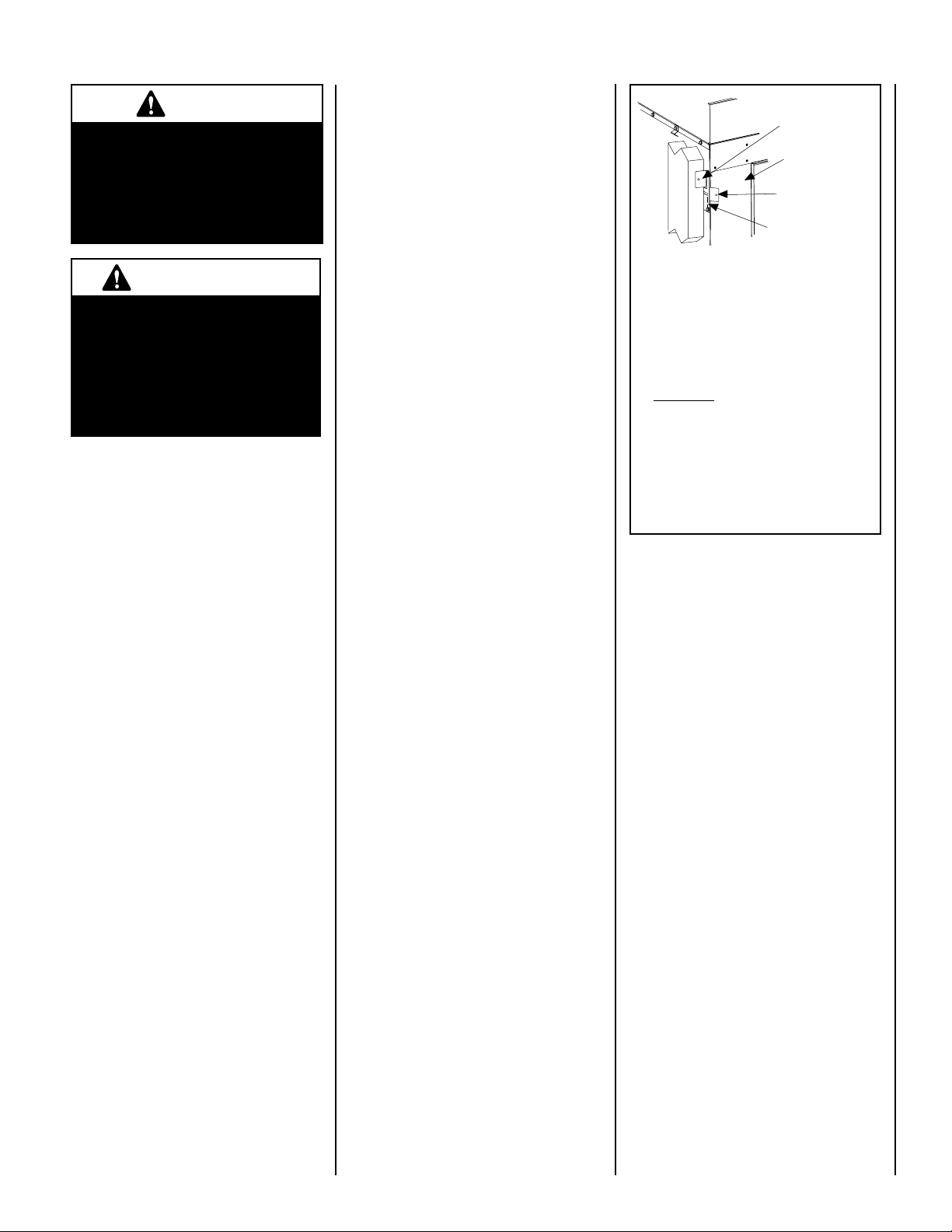
Left Side Front Corner of Fireplace Shown
(Right Side Requirements the Same)
Unit Being Secured By Its Nailing Flanges
To The Framing
Note: The nailing flanges, combustible members
and screw heads located in areas directly adjacent
to the nailing flanges, are EXEMPT from the 1/2”
clearance to combustible requirements for the
firebox outer wrapper. Combustible framing may be
in direct contact with the nailing flanges and may
be located closer than 1/2” from screw heads and
the firebox wrapper in areas adjacent to the nailing
flanges. Frame the opening to the exact dimensions
specified in the framing details of this manual.
Unit Being Secured by Its Nailing
Flanges to the Framing
Figure 11
The typical sequence of installation is outlined
below. However, each installation is unique
and may result in variations to the steps
described.
See the Page numbers references in the follow
ing steps for detailed procedures.
Step 1.
Step 2.
(Page 9) Construct the appliance
framing. Position the appliance within
the framing and secure with nailing
brackets.
(Page 11) Route gas supply line to
the right side.
Headers may be in direct contact with the
appliance top spacers but must not be sup
ported by them or notched to fit around them.
All construction above the appliance must be
self-supporting,
-
structural support.
The fireplace should be secured to the side
framing members using the unit's nailing
flanges - one top and bottom on each side of
the fireplace front (see
or their equivalent.
NOTE: DIAGRAMS & ILLUSTRATIONS ARE NOT TO SCALE.
DO NOT use the appliance for
Figure 11). Use 8d nails
-
9
E
A
B
D
Top View
Front View
5-3/32 (129)
Right Side View
14-1/8
8-1/2”
(216)
5-1/4”
(133)
(359)
26-15/32
(672)
C
25-29/32
(658)
25-1/2
(648)
7
2-1/2 (64)
(178)
19-5/8
(498)
Gas Inlet
(This
Side
Only)
Electrical
Inlet
8-3/8
(213)
F
G
H
J
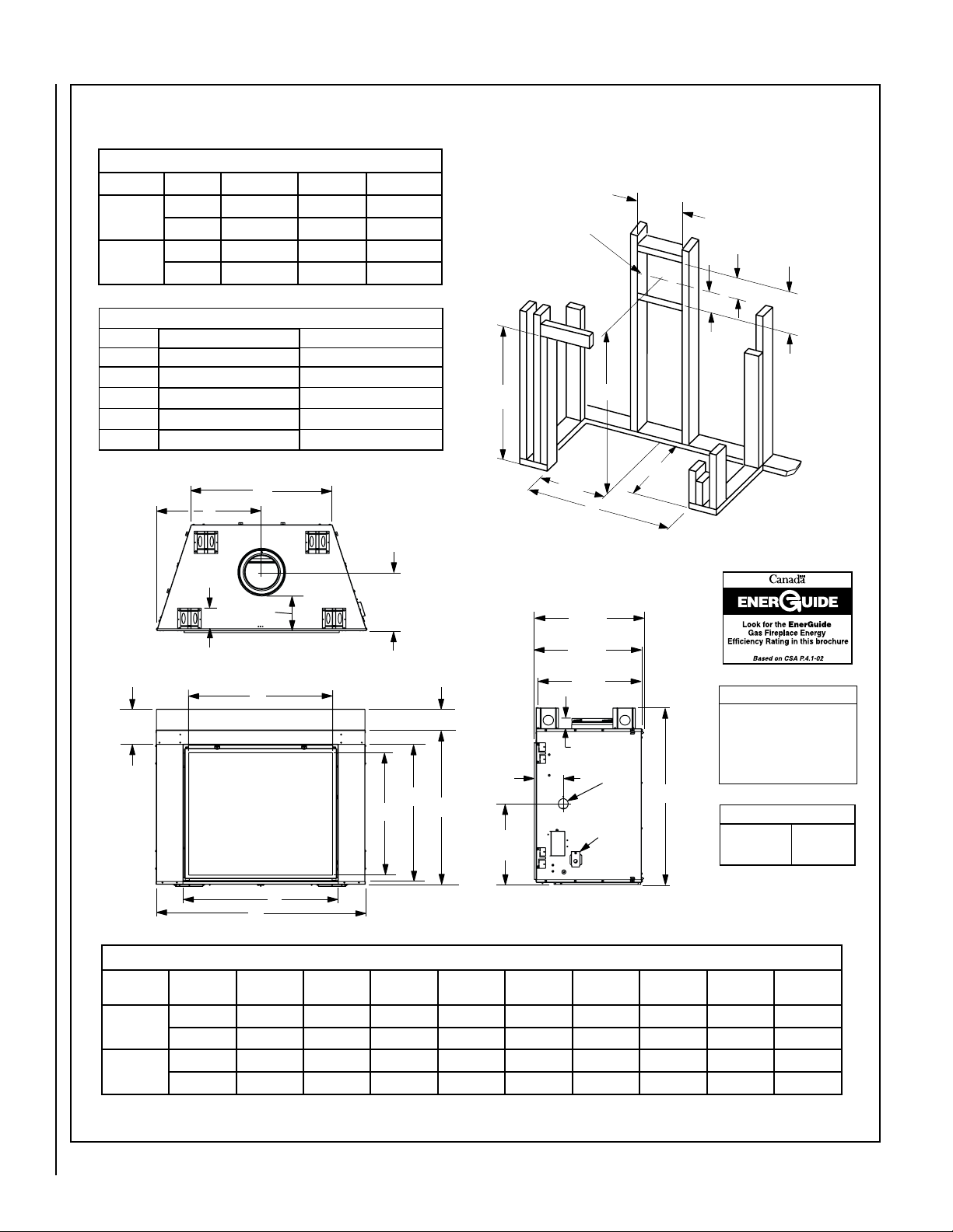
FIREPLACE AND FRAMING SPECIFICATIONS
A
B
C
8-1/2
(216)
13
(
330
)
VENT FRAMING
-
TOP VENT WITH 2 FEET
VERTICAL VENT AND
ONE 90° ELBOW
Framing should be constructed
of 2x4 or larger lumber.
Inches (mm)
(641)
25-1/4
15
(
381
)
6-1/2
(165)
1/2 A
Framing Dimensions
Models A B C
LSM40-2
LSM45-2
Models P4 P4
LSM40M 35% 38.1
LSM40E 35.8
LSM45M 50.8 42.3
LSM45E 51.2
in. 50-3/4 43 75-1/8
mm 1289 1092 1908
in. 56-7/8 48 80-1/16
mm 1445 1219 2034
Efficiencies %
Natural Gas Propane
Figure 12
Model
No.
LSM40-2
LSM45-2
Notes
Diagrams, illustrations and photographs are not to scale – consult
installation instructions. Pro duct
design s, mater ials, di mensions ,
specifications, colors and prices are
subject to change or discontinuance
without notice.
Vent Size
Co-axial DV
Vent Size
A B C D E F G H J
in. 50-5/8 37-1/4 42-7/8 25-5/16 34 37-5/8 33-3/32 29-9/32 34-3/4
mm 1286 946 1089 643 864 956 840 744 883
in. 56-11/16 42-1/4 47-7/8 28-3/8 40-1/8 43-5/8 38-3/32 34-1/2 40-59/64
mm 1440 1073 1216 721 1019 1108 968 876 1039
Fireplace Dimensions
8" Inner
11" Outer
10
NOTE: DIAGRAMS & ILLUSTRATIONS ARE NOT TO SCALE.