

OPERATOR'S MANUAL
MANUEL de L'UTILISATEUR
MANUAL del OPERADOR
Catalog No.
No de Cat.
Catálogo No.
6390-20
6394
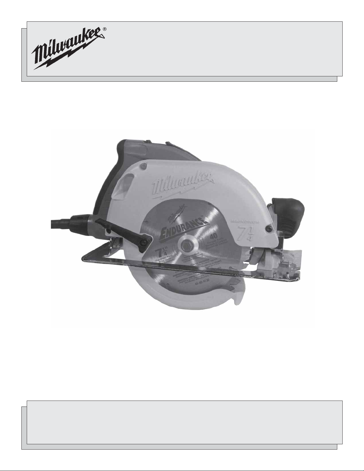
HEAVY-DUTY CIRCULAR SAW WITH TILT-LOK™ HANDLE
SCIES CIRCULAIRES INDUSTRIELLES AVEC POIGNEE « TILT-LOK™ »
SIERRA CIRCULAR PARA TRABAJO PESADO CON EMPUÑADURA
TIL T-LOK™ (INCLINABLE-FIJABLE)
TO REDUCE THE RISK OF INJURY, USER MUST READ AND UNDERSTAND OPERATOR'S MANUAL.
AFIN DE RÉDUIRE LE RISQUE DE BLESSURES, L'UTILISATEUR DOIT LIRE ET BIEN COMPRENDRE LE
MANUEL DE L'UTILISATEUR.
PARA REDUCIR EL RIESGO DE LESIONES, EL USUARIO DEBE LEER Y ENTENDER EL MANUAL DEL
OPERADOR.

GENERAL SAFETY RULES — FOR ALL POWER TOOLS
WARNING!
Failure to follow all instructions listed below may result in electric shock, fire and/or serious injury. The term "power tool" in
all of the warnings listed below refers to your mains-operated (corded) power tool or battery-opearted (cordless) power tool.
SAVE THESE INSTRUCTIONS
READ ALL INSTRUCTIONS
WORK AREA SAFETY
1. Keep work area clean and well lit. Cluttered or dark areas invite
accidents.
2. Do not operate power tools in explosive atmospheres, such
as in the presence of flammable liquids, gases, or dust. Power
tools create sparks which may ignite the dust or fumes.
3. Keep children and bystanders away while operating a power
tool. Distractions can cause you to lose control.
ELECTRICAL SAFETY
4. Power tool plugs must match the outlet. Never modify the
plug in any way. Do not use any adapter plugs with earthed
(grounded) power tools. Unmodified plugs and matching outlets
will reduce risk of electric shock.
5. Avoid body contact with earthed or grounded surfaces such
as pipes, radiators, ranges and refrigerators. There is an
increased risk of electric shock if your body is earthed or grounded.
6. Do not expose power tools to rain or wet conditions. Water
entering a power tool will increase the risk of electric shock.
7. Do not abuse the cord. Never use the cord for carrying, pull-
ing, or unplugging the power tool. Keep cord away from heat,
oil, sharp edges, or moving parts. Damaged or entangled cords
increase the risk of electric shock.
8. When operating a power tool outdoors, use an extension
cord suitable for outdoor use. Use of a cord suitable for outdoor
use reduces the risk of electric shock.
PERSONAL SAFETY
16. Do not force the power tool. Use the correct power tool for
your application. The correct power tool will do the job better and
safer at the rate for which it was designed.
17. Do not use the power tool if the switch does not turn it on
and off. Any power tool that cannot be controlled with the switch is
dangerous and must be repaired.
18. Disconnect the plug from the power source and/or the bat-
tery pack from the power tool before making any adjustments, changing accessories, or storing power tools. Such
preventive safety measures reduce the risk of starting the tool accidentally.
19. Store idle power tools out of the reach of children and do
not allow persons unfamiliar with the power tools or these
instructions to operate power tools. Power tools are danger-
ous in the hands of untrained users.
20. Maintain power tools. Check for misalignment or binding of
moving parts, breakage of parts and any other condition
that may affect the power tool's operation. If damaged, have
the power tool repaired before use. Many accidents are caused
by poorly maintained power tools.
21. Keep cutting tools sharp and clean. Properly maintained cutting
tools with sharp cutting edges are less likely to bind and are easier
to control.
22. Use the power tool, accessories and tool bits etc., in accor-
dance with these instructions and in the manner intended
for the particular type of power tool, taking into account the
working conditions and the work to be performed. Use of the
power tool for operations different from those intended could result in
a hazardous situation.
POWER TOOL USE AND CARE
SERVICE
9. Stay alert, watch what you are doing and use common sense
when operating a power tool. Do not use a power tool while
you are tired or under the influence of drugs, alcohol or medication. A moment of inattention while operating power tools may
result in serious personal injury.
10. Use safety equipment. Always wear eye protection. Safety
equipment such as dust mask, non-skid safety shoes, hard hat, or
hearing protection used for appropriate conditions will reduce personal injuries.
11. Avoid accidental starting. Ensure the switch is in the off-
position before plugging in. Carrying tools with your finger on
the switch or plugging in power tools that have the switch on invites
accidents.
12. Remove any adjusting key or wrench before turning the
power tool on. A wrench or a key left attached to a rotating part of
the power tool may result in personal injury.
13. Do not overreach. Keep proper footing and balance at all
times. This enables better control of the power tool in unexpected
situations.
14. Dress properly. Do not wear loose clothing or jewellery. Keep
your hair, clothing and gloves away from moving parts. Loose
clothes, jewellery, or long hair can be caught in moving parts.
15. If devices are provided for the connection of dust extrac-
tion and collection facilities, ensure these are connected
and properly used. Use of these devices can reduce dust-re-
lated hazards.
page 2
23. Have your power tool serviced by a qualified repair person
using only identical replacement parts. This will ensure that the
safety of the power tool is maintained.

SPECIFIC SAFETY RULES — CIRCULAR SAWS
1. Maintain labels and nameplates. These carry important informa-
tion. If unreadable or missing, contact a MILWAUKEE service facility
for a free replacement.
2. DANGER! Keep hands away from cutting area and blade. Keep
your second hand on auxiliary handle or motor housing. If
both hands are holding the saw, they cannot be cut by the blade.
Do not reach underneath the workpiece. The guard cannot protect you from the blade below the workpiece.
Adjust the cutting depth to the thickness of the workpiece.
Less than a full tooth of the blade teeth should be visible below the
workpiece.
3. Check lower guard for proper closing before each use. Do
not operate the saw if lower guard does not move freely and
close instantly. Never clamp or tie the lower guard into the open
position. If saw is accidentally dropped, lower guard may be bent.
Raise the lower guard with the retracting handle and make sure it
moves freely and does not touch the blade or any other part, in all
angles and depths of cut.
4. Check the operation and condition of the lower guard spring.
If the guard and the spring are not operating properly, they
must be serviced before use. Lower guard may operate slug-
gishly due to damaged parts, gummy deposits, or a buildup of debris.
5. Lower guard should be retracted manually only for special
cuts such as "Plunge Cuts" and "Compound Cuts". Raise
lower guard by retracting handle and as soon as blade enters the material, the lower guard must be released. For all
other sawing, the lower guard should operate automatically.
6. Always observe that the lower guard is covering the blade
before placing saw down on bench or floor. An unprotected,
coasting blade will cause the saw to walk backwards, cutting whatever is in its path. Be aware of the time it takes for the blade to stop
after switch is released.
7. NEVER hold piece being cut in your hands or across your leg.
Secure the workpiece to a stable platform. It is important to
support the work properly to minimize body exposure, blade binding,
or loss of control.
8. Hold power tools by insulated gripping surfaces when per-
forming an operation where the cutting tool may contact hidden wiring or its own cord. Contact with a "live" wire will make
exposed metal parts of the tool "live" and shock the operator.
9. When ripping always use a rip fence or straight edge guide.
This improves the accuracy of cut and reduces the chance for blade
binding.
10. Always use blades with correct size and shape (diamond vs.
round) arbor holes. Blades that do not match the mounting hardware of the saw will run eccentrically, causing loss of control.
11. Never use damaged or incorrect blade washers or bolts. The
blade washers and bolts were specially designed for your saw, for
optimum performance and safety of operation.
12. WARNING! Some dust created by power sanding, sawing, grinding,
drilling, and other construction activities contains chemicals known to
cause cancer, birth defects or other reproductive harm. Some examples of these chemicals are:
• lead from lead-based paint
• crystalline silica from bricks and cement and other masonry
products, and
• arsenic and chromium from chemically-treated lumber.
Your risk from these exposures varies, depending on how often you
do this type of work. To reduce your exposure to these chemicals:
work in a well ventilated area, and work with approved safety equipment, such as those dust masks that are specifically designed to filter
out microscopic particles.
13. Causes and Operator Prevention of KICKBACK:
KICKBACK is a sudden reaction to a pinched, bound or misaligned
saw blade, causing an uncontrolled saw to lift up and out of the
workpiece toward the operator.
When the blade is pinched or bound tightly by the kerf closing down,
the blade stalls and the motor reaction drives the unit rapidly back
toward the operator.
If the blade becomes twisted or misaligned in the cut, the teeth at the
back edge of the blade can dig into the top surface of the wood
causing the blade to climb out of the kerf and jump back toward
operator.
KICKBACK is the result of saw misuse and/or incorrect operating procedures or conditions and can be avoided by taking proper precautions as
given below:
14. Maintain a firm grip with both hands on the saw and position
your arms to resist KICKBACK forces. Position your body to
either side of the blade, but not in line with the blade. KICK-
BACK could cause the saw to jump backwards, but kickback forces
can be controlled by the operator, if proper precautions are taken.
15. When blade is binding, or when interrupting a cut for any
reason, release the trigger and hold the saw motionless in
the material until the blade comes to a complete stop. Never
attempt to remove the saw from the work or pull the saw
backward while the blade is in motion or KICKBACK may occur. Investigate and take corrective actions to eliminate the cause of
blade binding.
16. When restarting a saw in the workpiece, center the saw
blade in the kerf and check that saw teeth are not engaged
into the material. If saw blade is binding, it may walk up or KICK-
BACK from the workpiece as the saw is restarted.
17. Support large panels to minimize the risk of blade pinching
and KICKBACK. Large panels tend to sag under their own weight.
Supports must be placed under the panel on both sides, near the line
of cut and near the edge of the panel.
18. Do not use dull or damaged blade. Unsharpened or improperly
set blades produce narrow kerf causing excessive friction, blade
binding and KICKBACK.
19. Blade depth and bevel adjusting locking levers must be tight
and secure before making cut. If blade adjustment shifts while
cutting, it may cause binding and KICKBACK.
20. Use extra caution when making a "Plunge Cut" into existing
walls or other blind areas. The protruding blade may cut objects
that can cause KICKBACK.
page 3
GROUNDING EXTENSION CORDS
WARNING!
Improperly connecting the grounding wire can
result in the risk of electric shock. Check with a
qualified electrician if you are in doubt as to
whether the outlet is properly grounded. Do not
modify the plug provided with the tool. Never
remove the grounding prong from the plug. Do
not use the tool if the cord or plug is damaged. If
damaged, have it repaired by a MILWAUKEE
service facility before use. If the plug will not fit
the outlet, have a proper outlet installed by a
qualified electrician.
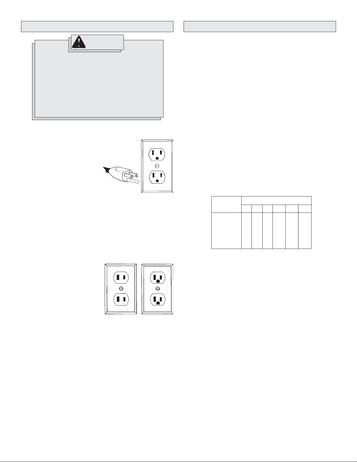
Grounded Tools:
Tools with Three Prong Plugs
Tools marked “Grounding Required”
have a three wire cord and three
prong grounding plug. The plug must
be connected to a properly grounded
outlet (See Figure A). If the tool should
electrically malfunction or break
down, grounding provides a low resistance path to carry electricity
away from the user, reducing the risk
of electric shock.
The grounding prong in the plug is connected through the green wire
inside the cord to the grounding system in the tool. The green wire in the
cord must be the only wire connected to the tool's grounding system and
must never be attached to an electrically “live” terminal.
Your tool must be plugged into an appropriate outlet, properly installed
and grounded in accordance with all codes and ordinances. The plug
and outlet should look like those in Figure A.
Fig. A
Grounded tools require a three wire extension cord. Double insulated
tools can use either a two or three wire extension cord. As the distance
from the supply outlet increases, you must use a heavier gauge extension cord. Using extension cords with inadequately sized wire causes a
serious drop in voltage, resulting in loss of power and possible tool
damage. Refer to the table shown to determine the required minimum
wire size.
The smaller the gauge number of the wire, the greater the capacity of the
cord. For example, a 14 gauge cord can carry a higher current than a 16
gauge cord. When using more than one extension cord to make up the
total length, be sure each cord contains at least the minimum wire size
required. If you are using one extension cord for more than one tool, add
the nameplate amperes and use the sum to determine the required minimum wire size.
Guidelines for Using Extension Cords
• If you are using an extension cord outdoors, be sure it is marked with
the suffix “W-A” (“W” in Canada) to indicate that it is acceptable for
outdoor use.
• Be sure your extension cord is properly wired and in good electrical
condition. Always replace a damaged extension cord or have it repaired by a qualified person before using it.
• Protect your extension cords from sharp objects, excessive heat and
damp or wet areas.
Recommended Minimum Wire Gauge
Nameplate
Amperes
8.1 - 12
12.1 - 15
15.1 - 20
for Extension Cords*
25'
0 - 5
5.1 - 8
16
16
14
12
10
Extension Cord Length
100'
14
12
10
10
150'
12
10
--
--
--
--
50'
16
16
14
12
10
75'
16
14
12
10
10
200'
12
--
--
--
--
Double Insulated Tools:
Tools with Two Prong Plugs
Tools marked “Double Insulated” do
not require grounding. They have a
special double insulation system
which satisfies OSHA requirements
and complies with the applicable
standards of Underwriters Laboratories, Inc., the Canadian Standard
Association and the National Electrical Code. Double Insulated tools may
be used in either of the 120 volt outlets shown in Figures B and C.
Fig. B
* Based on limiting the line voltage drop to five
volts at 150% of the rated amperes.
READ AND SAVE ALL INSTRUCTIONS
FOR FUTURE USE.
Fig. C
page 4
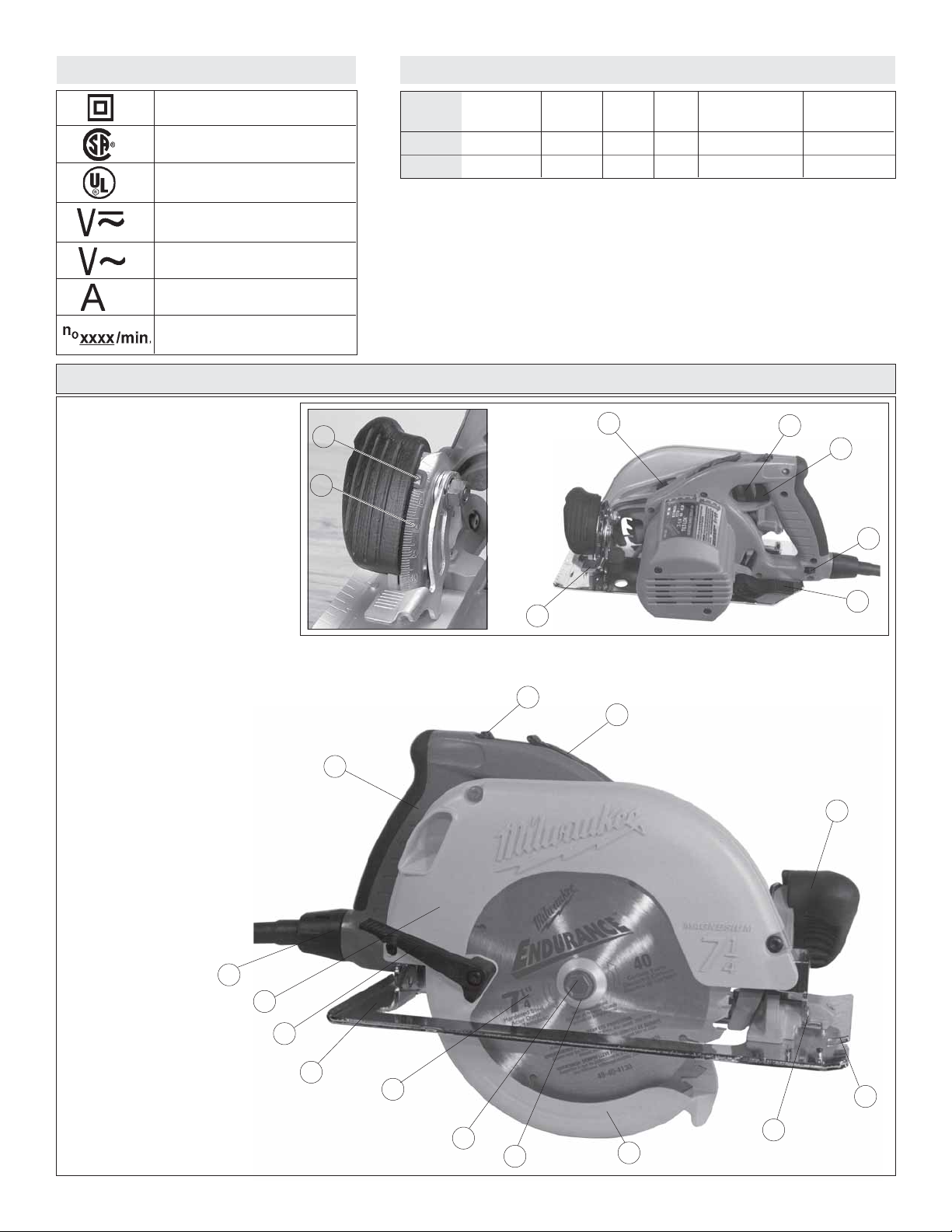
Symbology
Specifications
Double Insulated
Canadian Standards Association
Underwriters Laboratories, Inc.
Volts Alternating Current/
Direct Current
Volts Alternating Current
Amps
No Load Revolutions per Minute
(RPM)
1. Tilt-Lok™ handle
2. Handle lever release button
3. Handle release lever
4. Bevel scale
5. Bevel pointer
6. Bevel adjusting lever
7. Spindle lock button
8. Depth setting gauge (not shown)
9. Trigger
10. Cord release button
(Cat. No. 6394 only)
11. Depth adjusting lever
12. Front handle
13. Sight line
14. Rip fence slot
15. Lower guard
16. Blade flange
17. Blade bolt
18. Blade
19. Shoe
20. Lower guard lever
21. Upper guard
22. Positive-Lok® cord
(Cat. No. 6394 only)
Cat.
No.
6390-20
6394
Volts
120 AC/DC
120 AC Only
No Load
RPM
5800
5800
Blade
Size
7-1/4"
7-1/4"
Arbor
5/8"
5/8"
Depth of Cut
At 90°
0 to 2-15/32"
0 to 2-15/32"
Depth of Cut
at 45°
0 to 1-13/16"
0 to 1-13/16"
FUNCTIONAL DESCRIPTION
5
7
4
6
2
3
1
8
9
10
11
Cat. No. 6394
12
22
21
20
19
18
17
16
13
14
15
page 5
TOOL ASSEMBLY
WARNING!
To reduce the risk of injury, always unplug
tool before attaching or removing accessories
or making adjustments. Use only specifically
recommended accessories. Others may be
hazardous.
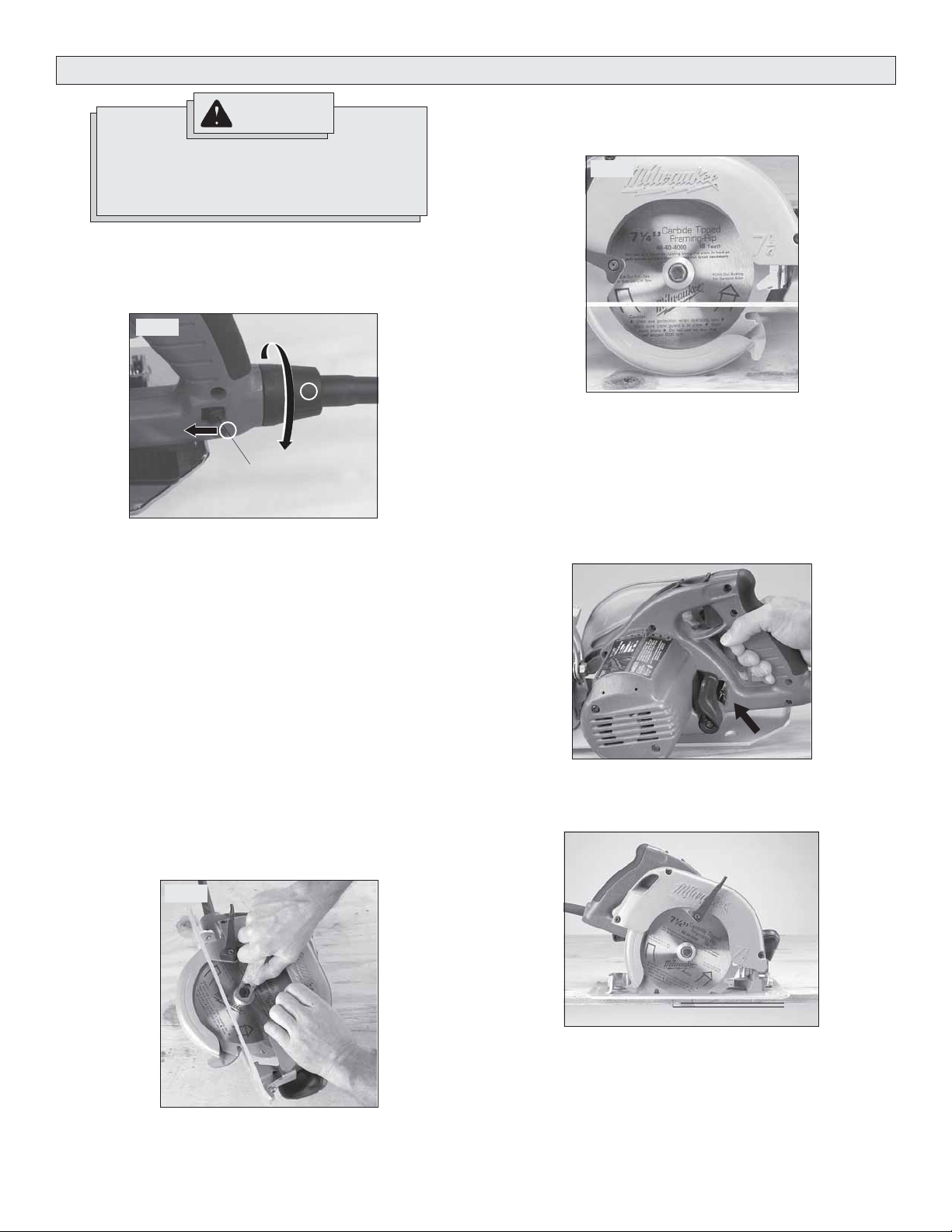
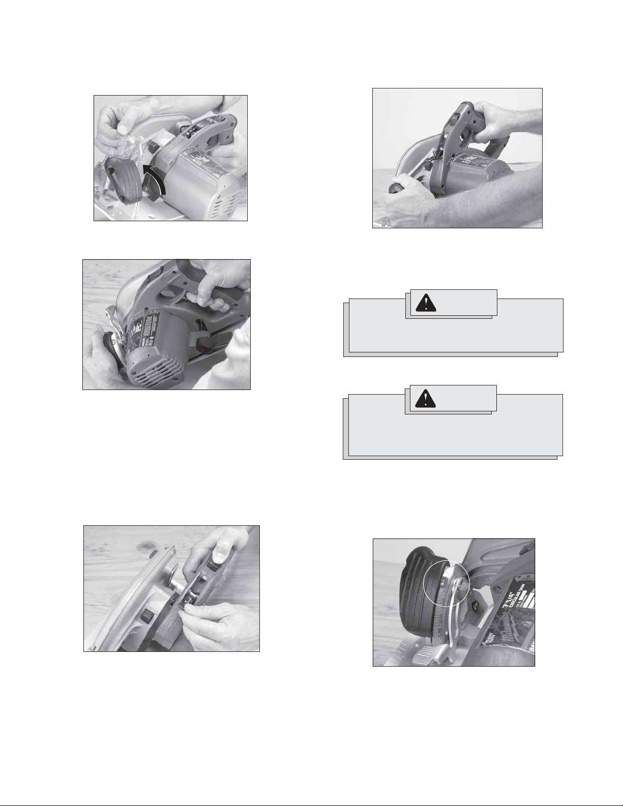
Removing and Replacing Positive-Lok® Cords (Fig. 1)
Cat. No. 6394
MILWAUKEE’S exclusive Positive-Lok® Cords provide instant field re-
placement or substitution. The Positive-Lok
firmly to the tool.
Fig. 1
1
Cord release button
1. To remove the Positive-Lok® Cord, push the cord release button in the
direction shown and turn the cord nut 1/4 turn to the left. Pull the
cord out.
2. To replace the Positive-Lok® Cord, align the connector keyways and
push the connector in as far as it will go. Turn the cord nut 1/4 turn to
the right to lock. The cord release button will click back into place.
®
feature secures the cord
2
4. T o install a blade, place the blade on the spindle with the teeth pointing
in the same direction as the arrow on the lower guard (Fig. 3). Release the lower guard lever.
Fig. 3
5. Place the blade flange on the spindle and hand tighten the bolt.
6. While holding the spindle lock button in, use the wrench to turn the bolt
clockwise and tighten.
Adjusting Depth (Figs. 4 & 5)
1. Unplug tool.
2. To adjust the depth of the cut, hold the saw by the Tilt-Lok™ handle
and loosen the depth adjusting lever by lifting it up and away from the
shoe (Fig. 4).
Fig. 4
Selecting Blade
Always use sharp blades. Dull blades tend to overload the tool and
increase the chance of KICKBACK (see page 8). Only use blades with a
maximum safe operating speed greater than the no load RPM marked on
the tool's nameplate. Read the blade manufacturer's instructions before
use.
Installing and Removing Blades (Figs. 2 & 3)
1. Unplug tool before installing or removing blades.
2. Place the saw on a flat surface with the blade facing upwards. To
remove the bolt from the spindle, push in the spindle lock button. While
holding the spindle lock button in, use the wrench provided with the
tool to turn the bolt counterclockwise (Fig. 2). Remove the bolt and
blade flange.
Fig. 2
3. Raise or lower the shoe to the desired position. Markings in 1/4"
increments are located on the inner side of the upper guard for depth
setting. For the proper depth setting, the blade should extend no more
than 1/4" below the material being cut (Fig. 5).
Fig. 5
1/4"
4. Move the depth adjusting lever towards the shoe and push down to
secure the position.
3. Slide the lower guard lever up to raise the lower guard. Remove the
blade from the spindle. Always clean the spindle, upper guard and
lower guard to remove any dirt and sawdust.
page 6
Adjusting Bevel Angle (Figs. 6 & 7)
1. Unplug tool.
2. To adjust the angle of the cut, hold the saw by the Tilt-Lok™ handle
and loosen the bevel adjusting lever by lifting it up towards the
blade (Fig. 6).
Fig. 6
4. To adjust the handle position, hold the front handle and rotate the TiltLok™ handle to the desired angle as indicated by the handle rotation
adjustment markings (Fig. 9). The Tilt-Lok™ feature has eight (8)
detents which allow the handle to snap into position. Allow the detent
to snap into place.
Fig. 9
3. Hold the front handle and rotate the saw by the Tilt-Lok™ handle to
the desired angle as indicated by the markings on the bevel scale
(Fig. 7).
Fig. 7
4. Move the bevel adjusting lever away from the blade and push down
to secure the position.
Adjusting Tilt-Lok™ Handle Angle (Figs. 8 & 9)
This circular saw is equipped with an adjustable handle. The Tilt-Lok™
feature allows the user to adjust the angle of the handle for optimum
cutting positions.
1. Unplug tool.
2. Press and hold the handle lever release button in.
3. Loosen the handle release lever by lifting it up and away from the
Tilt-Lok™ handle (Fig. 8).
Fig. 8
NOTE: The blade depth setting will determine the range of Tilt-Lok™
positions available for the application. See “Adjusting Depth” for instructions on adjusting the blade depth.
5. Push the handle release lever back into the handle until it snaps into
place.
WARNING!
Do not operate saw with handle lever release
button pressed in or with handle not locked into
position.
NOTE: The saw will not operate if the handle release lever is not
properly secured.
WARNING!
If the Tilt-Lok™ handle moves with the handle
release lever in the locked position, do not operate
saw. Return the circular saw to a MILWAUKEE
ser-vice facility for repair immediately.
Adjusting the Blade to Shoe (Figs. 10 & 11)
The shoe has been adjusted at the factor y to a 90 degree setting.
Inspect the saw regularly to make sure the blade is 90 degrees to the
shoe.
1. Unplug tool.
2. Set the bevel pointer to zero (Fig. 10).
Fig. 10
page 7

3. To make sure the blade is 90 degrees to the shoe, place saw on the
blade side and retract lower guard. Place a square against the blade
and shoe to inspect the degree setting (Fig. 11).
4. To adjust the degree setting, loosen the bevel adjusting lever up by
lifting it up towards the blade. Turn the bevel adjustment screw in or
out until the blade is at a 90 degree angle with the shoe.
5. Check that the bevel pointer is at 0 degrees. To adjust the bevel
pointer, loosen the two screws in the front handle and reposition the
bevel pointer to 0 degrees.
OPERATION
Fig.11
Bevel adjustment screw
WARNING!
To reduce the risk of injury, wear safety goggles
or glasses with side shields. Unplug the tool before changing accessories or making adjustments.
Causes and Operator Prevention of KICKBACK:
KICKBACK is a sudden reaction to a pinched, bound or mis-
aligned saw blade, causing an uncontrolled saw to lift up and
out of the workpiece toward the operator.
When the blade is pinched or bound tightly by the kerf, or cutting slot, closing down, the blade stalls and the motor reaction
drives the unit rapidly back toward the operator.
If the blade becomes twisted or misaligned in the cut, the teeth
at the back edge of the blade can dig into the top surface of the
wood causing the blade to climb out of the kerf and jump back
toward operator.
KICKBACK is the result of tool misuse and/or incorrect operating procedures or conditions and can be avoided by taking
proper precautions as given below:
1. Maintain a firm grip with both hands on the saw and position
your body and arm to allow you to resist KICKBACK forces.
KICKBACK forces can be controlled by the operator, if proper precautions are taken.
2. When blade is binding, or when interrupting a cut for any
reason, release the trigger and hold the saw motionless in
the material until the blade comes to a complete stop. Never
attempt to remove the saw from the work or pull the saw
backward while the blade is in motion or KICKBACK may occur. Investigate and take corrective actions to eliminate the cause of
blade binding.
3. When restarting a saw in the workpiece, center the saw
blade in the kerf, or cut, and check that saw teeth are not
engaged into the material. If saw blade is binding, it may walk up
or KICKBACK from the workpiece as the saw is restarted.
4. Support large panels to minimize the risk of blade pinching
and KICKBACK. Large panels tend to sag under their own weight.
Supports must be placed under the panel on both sides, near the line
of cut and near the edge of the panel.
5. Do not use dull or damaged blades. Unsharpened or improperly
set blades produce narrow kerf causing excessive friction, blade
binding and KICKBACK.
6. Blade depth and bevel adjusting locking levers must be tight
and secure before making cut. If blade adjustment shifts while
cutting, it may cause binding and KICKBACK.
7. Use extra caution when making a “Pocket Cut” into existing
walls or other blind areas. The protruding blade may cut objects
that can cause KICKBACK.
8. Set the depth of cut for no more than 1/8" to 1/4" greater than
the thickness of the stock. The less blade exposed, the less
chance of binding and KICKBACK. Before cutting, be sure depth and
bevel adjustments are tight.
9. Be cautious of pitchy, knotty, wet or warped stock. These are
most likely to create pinching conditions and possible KICKBACK. Do
not rip warped lumber. Avoid cutting nails.
10. Use a rip fence or edge guide when ripping. Guides improve
control and reduce blade binding.
11. Stay alert. Any distraction can cause twisting or binding. Repetitive
cuts may lull the user into careless movements.
General Operation (Figs. 12 & 13)
Always clamp the workpiece securely on a saw horse or bench
(Fig. 12). See “APPLICATIONS” for the correct way to support your work
in different situations.
Fig. 12
1. Draw a cutting line. Place the front of the shoe on the edge of the
workpiece without making blade contact. Hold the Tilt-Lok™ handle
with one hand and the front handle with the other (Fig. 13).
Fig. 13
2. Line up the sight line with your cutting line. Position your arms and
body to resist KICKBACK. Pull the trigger, allowing the motor to reach
full speed before beginning to cut.
3. While cutting, keep the shoe flat against the workpiece and maintain a
firm grip. Do not force the saw through the workpiece. Forcing a saw
can cause KICKBACK.
page 8
4. If making a partial cut, restarting in mid-cut or correcting direction,
allow the blade to come to a complete stop. To resume cutting, center
the blade in the kerf, back the saw away from cutting edge a few
inches, pull the trigger and re-enter the cut slowly.
5. If the saw binds and stalls, maintain a firm grip and release the trigger
immediately. Hold the saw motionless in the workpiece until the blade
comes to a complete stop.
6. After finishing a cut, be sure the lower guard closes and the blade
comes to a complete stop before setting the saw down.
Electric Brake (Cat. No. 6394)
Select models feature an electronic brake. The brake engages when the
trigger is released, causing the blade to stop and allowing you to proceed with your work. Generally, the saw blade stops within two seconds. However, there may be a delay between the time you release the
trigger and when the brake engages. Occasionally the brake may miss
completely. If the brake misses frequently, the saw needs servicing by
an authorized MILWAUKEE service facility. The brake is not a substitute
for the guard, and you must always wait for the blade to stop completely
before removing the saw from the workpiece. The correct brush grade
must be used for proper operation of the brake. Use only the correct
MILWAUKEE replacement brushes when servicing the tool.
APPLICATIONS
Troubleshooting
If the blade does not follow a straight line:
• Teeth are dull. This is caused by hitting a hard object such as a nail or
stone, dulling teeth on one side. The blade tends to cut to the side with
the sharpest teeth.
• Shoe is out of line or bent
• Blade is bent
• Rip fence or guide is not being used
If the blade binds, smokes or turns blue from friction:
• Blade is dull
• Blade is on backwards
• Blade is bent
• Blade is dirty
• Workpiece is not properly supported
• Incorrect blade is being used
WARNING!
To reduce the risk of injury, wear safety goggles
or glasses with side shields. Unplug the tool
before changing accessories or making
adjustments.
Selecting Tilt-Lok™ Handle Positions (Figs. 14, 15 & 16)
The Tilt-Lok™ handle is a feature which allows the user to adjust the
angle of the handle for optimum cutting positions. The Tilt-Lok™ handle
has eight (8) detents which allow the handle to snap into position
(Fig. 14). See “Adjusting Tilt-Lok™ Handle” for instuctions on adjusting
the handle. Refer to the chart below for suggested handle positions.
APPLICATION SUGGESTED TILT -LOK POSITIONS*
For cuts made at or near
waist level
For shallow cuts made at
or near waist level
For cuts made below the
waist, as in flooring applications
For cuts made overhead,
as in ceiling applications
* These are only suggested positions; the actual optimum cutting position may vary depending on the actual application and user preference.
Handle in lower positions (Fig. 15)
allows for more leverage when pushing the saw through the workpiece.
Handle in lower positions allows the
user to apply increased downward
force during shallow cuts.
Handle in higher positions (Fig. 16) reduce the amount of “bending over” by
the user. Higher handle positions allow
the user to apply an increased
downward force on the saw.
Handle in higher positions reduce the
amount of extended reach by the user
for overhead cuts. Higher handle positions allow the user to apply an
increased upward force on the saw.
Fig. 14
Fig. 15
Fig. 16
page 9
Cutting Large Panels (Fig. 17)
Large panels and long boards sag or bend if they are not correctly
supported. If you attempt to cut without leveling and properly supporting
the workpiece, the blade will tend to bind, causing KICKBACK.
Support large panels. Be sure to set the depth of the cut so that you only
cut through the workpiece, not through the supports.
Fig. 17
Ripping Wood
Ripping is cutting lengthwise with the grain. Select the proper blade for
your job. Use a rip fence for rips 4" wide or less. To install the rip fence,
slide the bar through the rip fence slot in either side of the shoe. The
width of the cut is the distance from the inside of the blade to the inside
edge of the rip fence. Adjust the rip fence for the desired width, and lock
the setting by tightening the rip fence screws.
When ripping widths greater than 4", clamp or tack 1" lumber to workpiece
and use the inside edge of the shoe as a guide.
Cross-Cutting Wood (Fig. 18)
Cross-cutting is cutting across the grain. Select the proper blade for
your job. Advance the saw slowly to avoid splintering the wood.
Fig. 18
Pocket Cutting (Fig. 19)
Pocket cuts are made in the middle of the workpiece when it can not be
cut from an edge. We recommend using a Sawzall® reciprocating saw or
jig saw for this type of cut. However, if you must use a circular saw to
make a pocket cut, USE EXTREME CAUTION. To maintain control of the
saw during pocket cutting, keep both hands on the saw (Fig. 19).
Fig. 19
1. Beginning at a corner, line up the sight line with your cutting line. Tilt
the saw forward, firmly fixing the front of the shoe on the workpiece.
The blade should be just above cutting line, but not touching it. Raise
the lower guard using the lower guard lever.
2. Pull the trigger, allowing the blade to come up to full speed. Using the
front of the shoe as a hinge point, gradually lower the back end of the
saw into the workpiece.
3. When the shoe rests flat against workpiece, release the lower guard
lever. Advance the saw to the far corner. Release the trigger and
allow the blade to come to a complete stop before removing it from
workpiece. Repeat the above steps for each side of the opening. Use
a Sawzall® reciprocating saw, jig saw or small hand saw to finish the
corners if they are not completely cut through.
Cutting Masonry and Metal
Although MILWAUKEE Circular Saws are primarily designed and intended for cutting wood, they may also be used with abrasive cutting
wheels or dry cutting diamond blades for cutting metal or masonry.
WARNING!
To reduce the risk of electric shock, check work
area for hidden pipes and wires before making
pocket cuts.
WARNING!
Only use abrasive cutting wheels with a
maximum safe operating speed greater than the
RPM marked on the tool's nameplate.
When cutting masonry, use a dry cutting diamond blade. Make successive passes at depths of less than 1/4" to achieve the desired depth.
Cutting at a depth of more than 1/4" will damage the wheel. Frequently
clean dust from air vents and guards. Always wear a dust mask.
When cutting light gauge sheet metal, use an aluminum oxide abrasive
cutting wheel or an appropriate blade designed specifically for cutting
metal. Set the depth of cut for 1/8" to 1/4" greater than the thickness of
the material you are cutting. Protect everyone in the area from sparks.
WARNING!
Dust, chips and grit can cause the guard to hang
up at any time. If the saw is used with an abra
sive cutting wheel or dry cutting diamond blade,
reserve and mark it for that use only. Before
using it for wood cutting, return it to a
MILWAUKEE service facility for cleaning and
testing.
page 10
 Loading...