

Milwaukee 6955-20 User Manual
Cat. No.
No de Cat.
6955-20
OPERATOR'S MANUAL
MANUEL de L'UTILISATEUR
MANUAL del OPERADOR
WITH
.
R
SECURE
YS
RACKET
FIXE
HANGE
E
C
WA
DB
S
E
TD
AL
DE
GUAR
BLAD
AME.
OUJOURS
G
T
SUPPOR
L'AIDE
N
AL
I
À
E
LE
N
AFTER
T
ÉL
T
EBE
R
R
O
N
P
E
ED
O
WA
S
M
CHANG
ES
L
E
SCREWS
E
PR
S
PROTECTION
S
AR
I
Z
E
AVOIR
S
BOTH
N
SIEM
A
I
FD
ERT
AF
PRÈS
AMBO
A
AV
I
SA
C
VI
N
CON
E
DISPOSITI
TOR
RT
DEUX
VE
D
A
12" SLIDING DUAL BEVEL MITER SAW WITH DIGITAL FINE ADJUST
SCIE À ONGLETS COULISSANTE À DOUBLE BISEAU DE 305 mm (12 PO)
AVEC FONCTION DE RÉGLAGE NUMÉRIQUE PRÉCIS
SIERRA INGLETEADORA DE BISEL DOBLE DESLIZABLE DE 305 mm
(12 PULG.) CON AJUSTE FINO DIGITAL
TO REDUCE THE RISK OF INJURY, USER MUST READ OPERATOR'S MANUAL.
AFIN DE RÉDUIRE LE RISQUE DE BLESSURES, L'UTILISATEUR DOIT LIRE LE
MANUEL DE L'UTILISATEUR.
PARA REDUCIR EL RIESGO DE LESIONES, EL USUARIO DEBE LEER EL MANUAL
DEL OPERADOR.

GENERAL SAFETY RULES
WARNING
READ AND UNDERSTAND ALL INSTRUCTIONS
Failure to follow all instructions listed below, may result in electric shock, fi re
and/or serious personal injury.
SAVE THESE INSTRUCTIONS
WORK AREA
1. Keep work area clean and well lit. Clut-
tered, dark work areas invite accidents.
2. Avoid dangerous environments. Do not
use your power tool in rain, damp or wet
locations or in the presence of explosive
atmospheres (gaseous fumes, dust or
fl ammable materials). Remove materials
or debris that may be ignited by sparks.
3. Keep bystanders away. Children and
bystanders should be kept at a safe
distance from the work area to avoid
distracting the operator and contacting
the tool or extension cord.
4. Protect others in the work area from
debris such as chips and sparks. Provide
barriers or shields as needed.
5. Make workshop child proof with pad-
locks, master switches, or by removing
starter keys.
ELECTRICAL SAFETY
6. Grounded tools must be plugged
into an outlet properly installed and
grounded in accordance with all codes
and ordinances. Never remove the
grounding prong or modify the plug in
any way. Do not use any adaptor plugs.
Check with a qualifi ed electrician if you
are in doubt as to whether the outlet is
properly grounded. If the tool should
electrically malfunction or break down,
grounding provides a low resistance path
to carry electricity away from the user.
7. Double insulated tools are equipped
with a polarized plug (one blade is
wider than the other). This plug will
fi t in a polarized outlet only one way.
If the plug does not fit fully in the
outlet, reverse the plug. If it still does
not fi t, contact a qualifi ed electrician
to install a polarized outlet. Do not
change the plug in any way. Double
insulation eliminates the need for
the three wire grounded power cord and
grounded power supply system.
8. Guard against electric shock. Prevent
body contact with grounded surfaces
such as pipes, radiators, ranges and
refrigerators. When making blind or
plunge cuts, always check the work area
for hidden wires or pipes. Hold your tool
by insulated nonmetal grasping surfaces.
Use a Ground Fault Circuit Interrupter
(GFCI) to reduce shock hazards.
9. Do not expose to rain or use in damp
locations.
10. Do not abuse the cord. Never use the
cord to carry the tools or pull the plug
from an outlet. Keep cord away form
heat, oil, sharp edges or moving parts.
Replace damaged cords immediately.
Damaged cords increase the risk of
electric shock.
PERSONAL SAFETY
11. Know your power tool. Read this
manual carefully to learn your power
tool’s applications and limitations as well
as potential hazards associated with this
type of tool.
12. Stay alert, watch what you are doing,
and use common sense when operating a power tool. Do not use tool while
tired or under the infl uence of drugs,
alcohol, or medication. A moment of
inattention while operating power tools
may result in serious personal injury.
13. Dress properly. Do not wear loose
clothing or jewelry. W ear a protective hair
covering to contain long hair. These may
be caught in moving parts. When working outdoors, wear rubber gloves and
insulated non-skid footwear. Keep hands
and gloves away from moving parts.
14. Reduce the risk of unintentional start-
ing. Be sure your tool is turned off before
plugging it in. Do not use a tool if the
power switch does not turn the tool on
and off. Do not carry a plugged-in tool
with your fi nger on the switch.
2 3
15. Remove all adjusting keys and wrenches. Make a habit of checking that adjust-
ing keys, wrenches, etc. are removed
from the tool before turning it on.
16. Do not overreach. Maintain control.
Keep proper footing and balance at all
times. Maintain a fi rm grip. Use extra
care when using tool on ladders, roofs,
scaffolds, etc.
17. Use safety equipment. Everyone in the
work area should wear safety goggles
or glasses with side shields complying
with current safety standards. Everyday
eyeglasses only have impact resistant
lenses. They are not safety glasses. Wear
hearing protection during extended use
and a dust mask for dusty operations.
Hard hats, face shields, safety shoes, etc.
should be used when specifi ed or neces-
sary. Keep a fi re extinguisher nearby.
18. Keep guards in place and in working
order.
19. Never stand on tool. Serious injury could
occur if the tool is tipped or if the cutting
tool is unintentionally contacted.
20. Keep hands away from all cutting
edges and moving parts.
TOOL USE AND CARE
21. Secure work. Use a clamp, vise or
other practical means to hold your work
securely, freeing both hands to control
the tool.
22. Do not force tool. Your tool will perform
best at the rate for which it was designed.
Excessive force only causes operator
fatigue, increased wear and reduced
control.
23. Use the right tool. Do not use a tool or
attachment to do a job for which it is not
recommended. For example, do not use
a circular saw to cut tree limbs or logs.
Do not alter a tool.
24. Unplug tool when it is not in use, before
changing accessories or performing recommended maintenance.
25. Store idle tools. When not in use, store
your tool in a dry, secured place. Keep
out of reach of children.
26. Never leave the tool running unat-
tended. Turn power off. Do not leave the
tool until it comes to a complete stop.
27. Check for damaged parts. Inspect
guards and other parts before use. Check
for misalignment, binding of moving
parts, improper mounting, broken parts
and any other conditions that may affect
operation. If abnormal noise or vibration
occurs, turn the tool off immediately
and have the problem corrected before
further use. Do not use a damaged tool.
Tag damaged tools “DO NOT USE” until
repaired. A guard or other damaged part
should be properly repaired or replaced
by a MILWAUKEE service facility. For all
repairs, insist on only identical replacement parts.
28. Use proper accessories. Consult this
manual for recommended accessories.
Using improper accessories may be hazardous. Be sure accessories are properly
installed and maintained. Do not defeat a
guard or other safety device when installing an accessory or attachment.
29. Maintain tools carefully. Keep handles
dry, clean and free from oil and grease.
Keep cutting edges sharp and clean. Follow instructions for lubricating and changing accessories. Periodically inspect tool
cords and extension cords for damage.
Have damaged parts repaired or replaced
by a MILWAUKEE service facility.
30. Maintain labels & nameplates. These
carry important information. If unreadable or missing, contact a MILWAUKEE
service facility for a free replacement.
SERVICE
31. Tool service must be performed only
by qualifi ed repair personnel. Service
or maintenance performed by unqualifi ed
personnel may result in a risk of injury.
32. When servicing a tool, use only identi-
cal replacement parts. Follow instructions in the maintenance section of
this manual. Use of unauthorized parts or
failure to follow maintenance instructions
may create a risk of shock or injury.
SPECIFIC SAFETY RULES
1. Always keep hands away from the
path of the saw blade.
2. Never reach around, under or across
blade.
3. Do not place hands under the saw
motor or in the path of the blade. Do
not retrieve a piece of material that is
cut off while the blade is rotating. Never
place hands or fi ngers behind or in front
of the saw blade.
4. Check guards for smooth operation
before each use.
5. Do not defeat the guards or operate
the tool without the guards in place.
6. Avoid kick back. Kick back is a violent
reaction to a pinched or binding blade,
which throws the saw head upward and
towards the operator. Proper workpiece
selection and support, proper blade
selection and maintenance, and even
feed rate are essential to reduce the risk
of kick back.
7. Always support work properly. Use
the fence, support blocks, auxiliary work
support or clamps to keep workpiece
secure. Always support the free end
of the workpiece and support all small
workpieces. Workpieces that bow and
pinch the blade may result in kick back.
Do not perform any operations freehand
(unsupported).
8. Thin material tends to warp or sag and
must be well-supported over its entire
length to avoid pinching the blade.
9. Position fence properly. The fence
can be adjusted for compound cuts and
miter cuts. Always make sure the fence
is adjusted for the intended cut. Never
operate the saw without the fence in
place.
10. Be sure the miter angle lock knob
and the bevel adjustment lever are
tightened securely before making
cuts.
11. Use the right blade. Use only recom-
mended blade types and sizes with
proper mounting holes, rated at least
5500 RPM. Follow the rotation arrow
on the blade to be sure you install it
properly. Keep saw blades sharp to help
prevent cracking and grabbing. Never
use defective or incorrect washers or
bolts.
12. Do not use abrasive wheels with the
miter saw.
13. Keep blades clean and sharp. An
unsharpened or improperly sharpened
blade produces a narrow kerf and is
likely to be pinched by the workpiece. A
dull blade produces excessive friction
which can cause the blade to warp or
bind. Be sure the blade screw is tight
to prevent slipping or loosening during
operation.
14. Wait for the blade to reach full speed
before lowering the saw head to make
a cut.
15. Push the saw through the workpiece.
Do not pull the saw through the
workpiece. To make a cut, raise saw
head and pull it out OVER the workpiece
WITHOUT cutting, start the motor, wait
a few seconds for the blade to reach full
speed, press down on saw head, and
push saw head through the cut.
16. If the blade stalls, do not turn the
switch on and off. A dull blade or
excess pressure may cause stalling.
Release the switch immediately if the
blade binds or the saw stalls and remove
the saw from the cut.
17. Restarting in mid-cut. If you stop the
saw in mid-cut, allow the blade to stop,
then raise the saw out of the cut. Then
restart the saw.
18. Do not lock the trigger in the on posi-
tion.
19. Keep the cord away from the cutting
area and position it so that it will not be
tripped over or caught on the workpiece
while you are cutting.
20. Avoid cutting nails. Inspect for and
remove all nails before cutting.
21. Always wait for the blade to stop
completely before changing positions,
retrieving a cut-off piece, or preparing
the next cut. Unplug the tool before
tightening blade screw, servicing, making adjustments, transporting or moving
the saw to another location.
22. Lock the saw head down and lock the
sliding mechanism before transporting.
23. WARNING: Some dust created by
power sanding, sawing, grinding, drilling, and other construction activities
contains chemicals known to cause
cancer, birth defects or other reproductive harm. Some examples of these
chemicals are:
• lead from lead-based paint
• crystalline silica from bricks and cement
and other masonry products, and
• arsenic and chromium from chemicallytreated lumber.
Your risk from these exposures varies,
depending on how often you do this
type of work. To reduce your exposure
to these chemicals: work in a well ventilated area, and work with approved
safety equipment, such as those dust
masks that are specifi cally designed to
fi lter out microscopic particles.
4 5
Improperly connecting the grounding
wire can result in the risk of electric
shock. Check with a qualifi ed electri-
cian if you are in doubt as to whether
the outlet is properly grounded. Do
not modify the plug provided with
the tool. Never remove the grounding
prong from the plug. Do not use the
tool if the cord or plug is damaged.
If damaged, have it repaired by a
MILWAUKEE service facility before
use. If the plug will not fi t the outlet,
have a proper outlet installed by a
qualifi ed electrician.
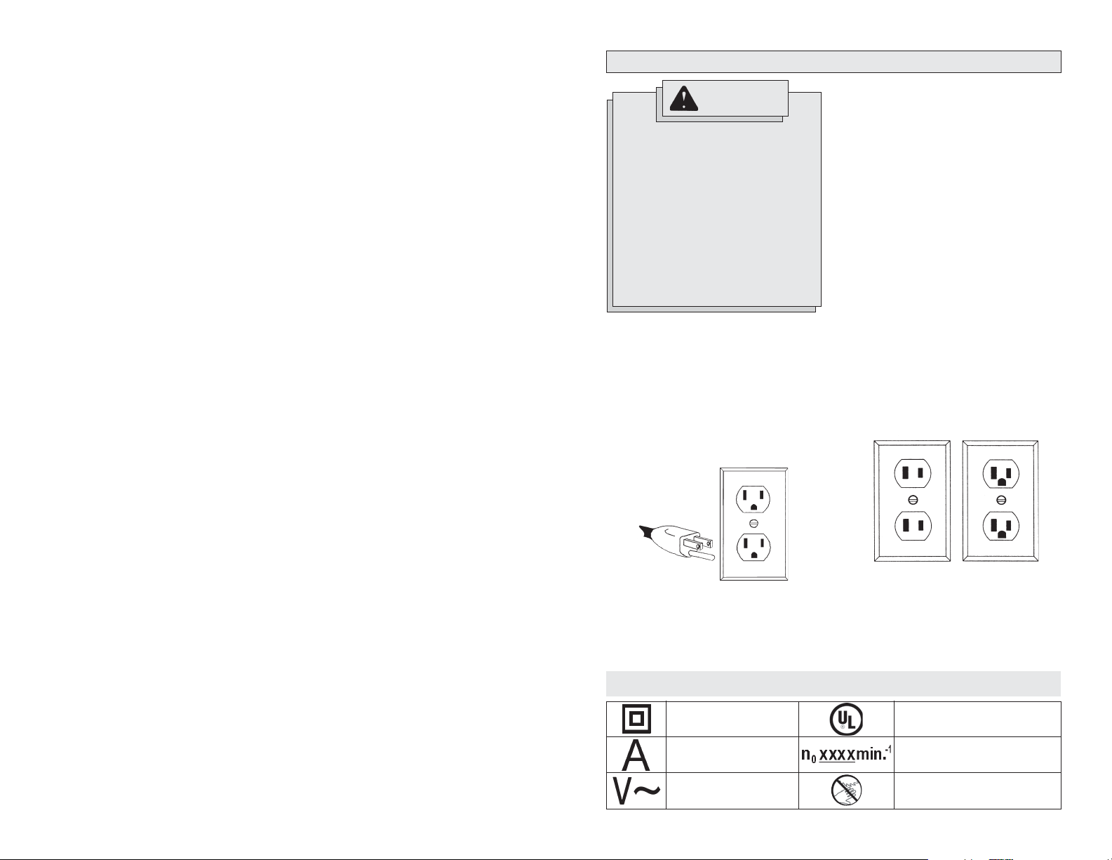
Grounded Tools:
Tools with Three Prong Plugs
Tools marked “Grounding Required” have a
three wire cord and three prong grounding
plug. The plug must be connected to a properly grounded outlet (See Figure A). If the
tool should electrically malfunction or break
down, grounding provides a low resistance
path to carry electricity away from the user,
reducing the risk of electric shock.
Fig. A
WARNING
Double Insulated
Amperes
Volts Alternating Current
GROUNDING
Symbology
The grounding prong in the plug is connected
through the green wire inside the cord to
the grounding system in the tool. The green
wire in the cord must be the only wire connected to the tool's grounding system and
must never be attached to an electrically
“live” terminal.
Your tool must be plugged into an appropriate outlet, properly installed and grounded in
accordance with all codes and ordinances.
The plug and outlet should look like those
in Figure A.
Double Insulated Tools:
Tools with Two Prong Plugs
Tools marked “Double Insulated” do not
require grounding. They have a special
double insulation system which satisfies
OSHA requirements and complies with
the applicable standards of Underwriters
Laboratories, Inc., the Canadian Standard
Association and the National Electrical
Code. Double Insulated tools may be used
in either of the 120 volt outlets shown in
Figures B and C.
Fig. B
Underwriters Laboratories, Inc.
No Load Revolutions per
Minute (RPM)
Always keep hands away from
the path of the saw blade.
Fig. C
EXTENSION CORDS
FUNCTIONAL DESCRIPTION
Grounded tools require a three wire extension cord. Double insulated tools can use
either a two or three wire extension cord.
As the distance from the supply outlet
increases, you must use a heavier gauge
extension cord. Using extension cords with
inadequately sized wire causes a serious
drop in voltage, resulting in loss of power
and possible tool damage. Refer to the table
shown to determine the required minimum
wire size.
The smaller the gauge number of the wire,
the greater the capacity of the cord. For example, a 14 gauge cord can carry a higher
Guidelines for Using Extension Cords
• If you are using an extension cord outdoors, be sure it is marked with the suffi x
“W-A” (“W” in Canada) to indicate that it
is acceptable for outdoor use.
• Be sure your extension cord is properly wired and in good electrical
condition. Always replace a damaged
extension cord or have it repaired by a
qualifi ed person before using it.
• Protect your extension cords from sharp
objects, excessive heat and
damp or wet areas.
current than a 16 gauge cord. When using
more than one extension cord to make up
the total length, be sure each cord contains
at least the minimum wire size required. If
you are using one extension cord for more
than one tool, add the nameplate amperes
and use the sum to determine the required
minimum wire size.
Recommended Minimum Wire Gauge
for Extension Cords*
Nameplate
Amperes
0 - 2.0
2.1 - 3.4
3.5 - 5.0
5.1 - 7.0
7.1 - 12.0
12.1 - 16.0
16.1 - 20.0
Extension Cord Length
25'
18
18
18
18
16
14
12
* Based on limiting the line voltage drop to
fi ve volts at 150% of the rated amperes.
READ AND SAVE ALL INSTRUCTIONS FOR FUTURE USE.
Specifi cations
Cat.
No.
6955-20
Volts
AC
120
Amps
15
No Load
RPM
3 200
Arbor
Size
5/8"
Blade
Size
12"
Capacities
Compound Cuts
45° Miter and 45° Bevel
Left Bevel
9.51" W at
2.25" H
Max Height
at 90°
6.55" H at
2.10" W
Miter Cuts
Max Height
at 45°
6.55" H at
.40" W
Max Width
at 90°
13.5" W at
4.02" H
Max Width
at 45°
9.51" W at
4.02" H
50'
18
18
18
16
14
12
10
Weight
65 lbs
75'
100'
18
18
18
16
16
14
14
12
12
10
10
Right Bevel
9.51" W at
1.9" H
150'
16
14
12
12
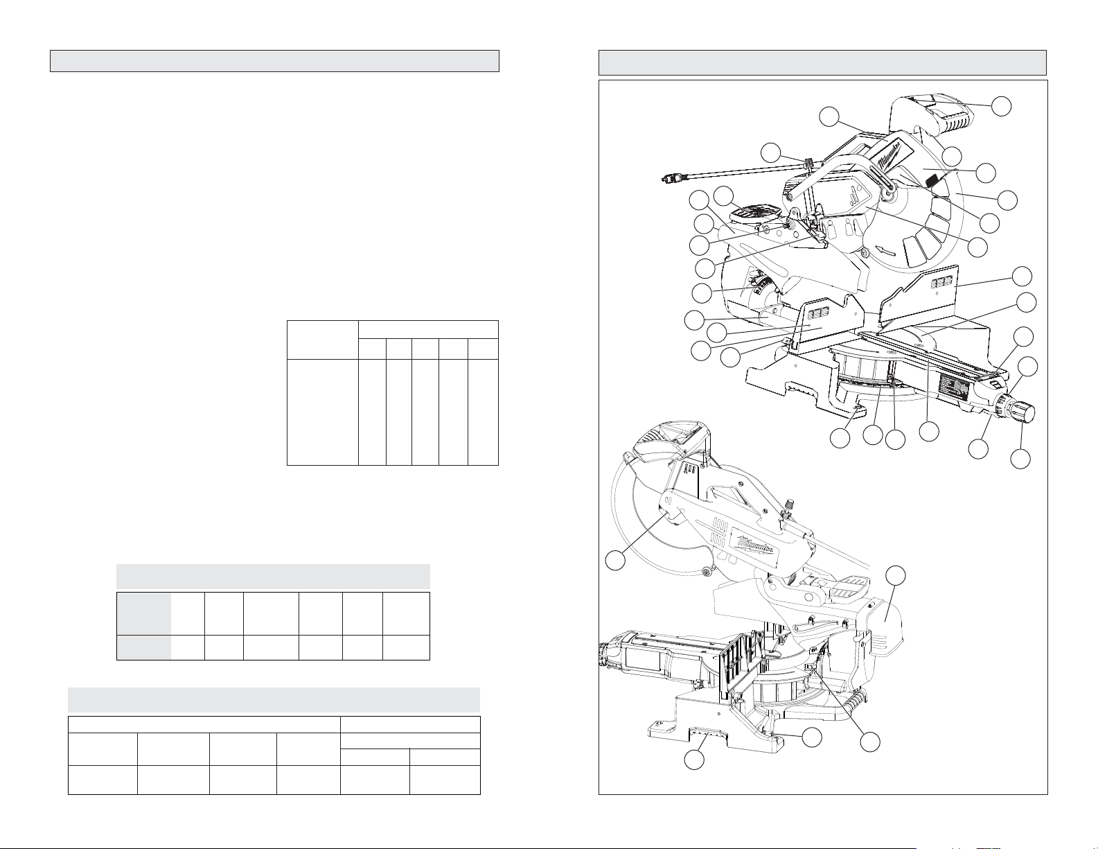
1. Saw head
2. Light on/off switch
3 On/Off trigger
4. Upper guard
5. Lower guard
6. Guard bracket
7. Lights
8. Fence
9. Turntable
10. Digital miter
angle readout
11. Fine adjustment
ring
12. Miter angle
lock knob
20
13. Detent lever
14. Adjustable kerf
plates
15. Miter angle pointer
16. Miter angle scale
28
32
25
23
21
24
22
8
19
26
18
27
31
1
2
3
WITH
.
R
SECURE
S
ACKET
XE
I
Y
R
F
HANGE
B
E
C
WA
D
S
E
TD
AL
DE
GUAR
BLAD
AME.
OUJOURS
G
T
SUPPOR
L'AIDE
N
AL
I
À
E
LE
N
AFTER
T
ÉL
T
EBE
R
R
D
N
PO
E
E
O
WA
S
M
CHANG
ES
L
E
SCREWS
E
PR
S
R
OIR
PROTECTION
S
A
I
Z
E
S
BOTH
N
SIEM
RT
A
I
FD
E
F
RÈSAV
A
P
AMBO
A
AV
I
SA
VI
NC
E
DISPOSITI
RCON
O
T
RT
DEUX
VE
D
A
4
5
6
7
8
9
10
11
17
16
30
14
15
17. Mounting holes (4)
18. Fence lock knob
19. Face board mounting
holes (4)
20. Slide rails
21. Bevel angle scale
29
22. Depth stop paw
23. Head lock-down pin
24. Dust ejection port
25. Dust chute
26. Bevel adjustment
lever
27. Depth stop adjustment knob
28. Spindle lock
29. Dust elbow (Dust bag
not shown)
30. Slide rail lock
31. Wrench storage
32. Carrying handles
13
12
6 7

FEATURES
Miter system
The Milwaukee 6955-20 Miter Saw uses a
heavy duty steel plate with detents (stops).
This steel plate is extremely durable and
provides for repeatable accuracy at each
detent. The miter angle can be set using
detents for commonly cut angles at 0°, 15°,
22.5° 31.62°, 45° Right and Left and 60°
Right. The 6955-20 has a miter range from
55° on the left to 60° on the right. An industrial grade bearing allows the turntable to be
quickly and accurately adjusted to any angle
across the miter range.
Miter Angle Fine Adjust
In certain fi nish carpentry applications like
casing a window or door, it is necessary to
compensate for a non-square situation by
making a precision miter angle adjustment to
the turntable. The Milwaukee miter angle fi ne
adjust system makes this process quick and
easy, especially when the saw is positioned
near a miter detent (stop).
Digital Miter Angle Readout
The Milwaukee 6955-20 has a Digital Miter
Angle Readout at the front of the turntable
that displays the miter angle of the turntable
to a resolution of 0.1°. The Digital Miter
Angle Readout is based on the mechanical
accuracy of the miter angle detent plate. It
calibrates itself each time the turntable is
placed in a miter detent and it requires no
adjustment.
Using the Miter Angle Fine Adjust in conjunction with the Digital Miter Angle Readout, it
is easy to make accurate minor angle adjustments anywhere along the miter range.
Using these systems together makes it easy
to re-position the turntable and repeat any
miter angle setting.
When the turntable is positioned at a LEFT
miter angle the digital readout will display
with a (-) symbol in front of the angle (for
example: -22.5° or -44.7°). When the turntable is positioned at a RIGHT miter angle
the digital readout will display as follows:
22.5° or 44.7°.
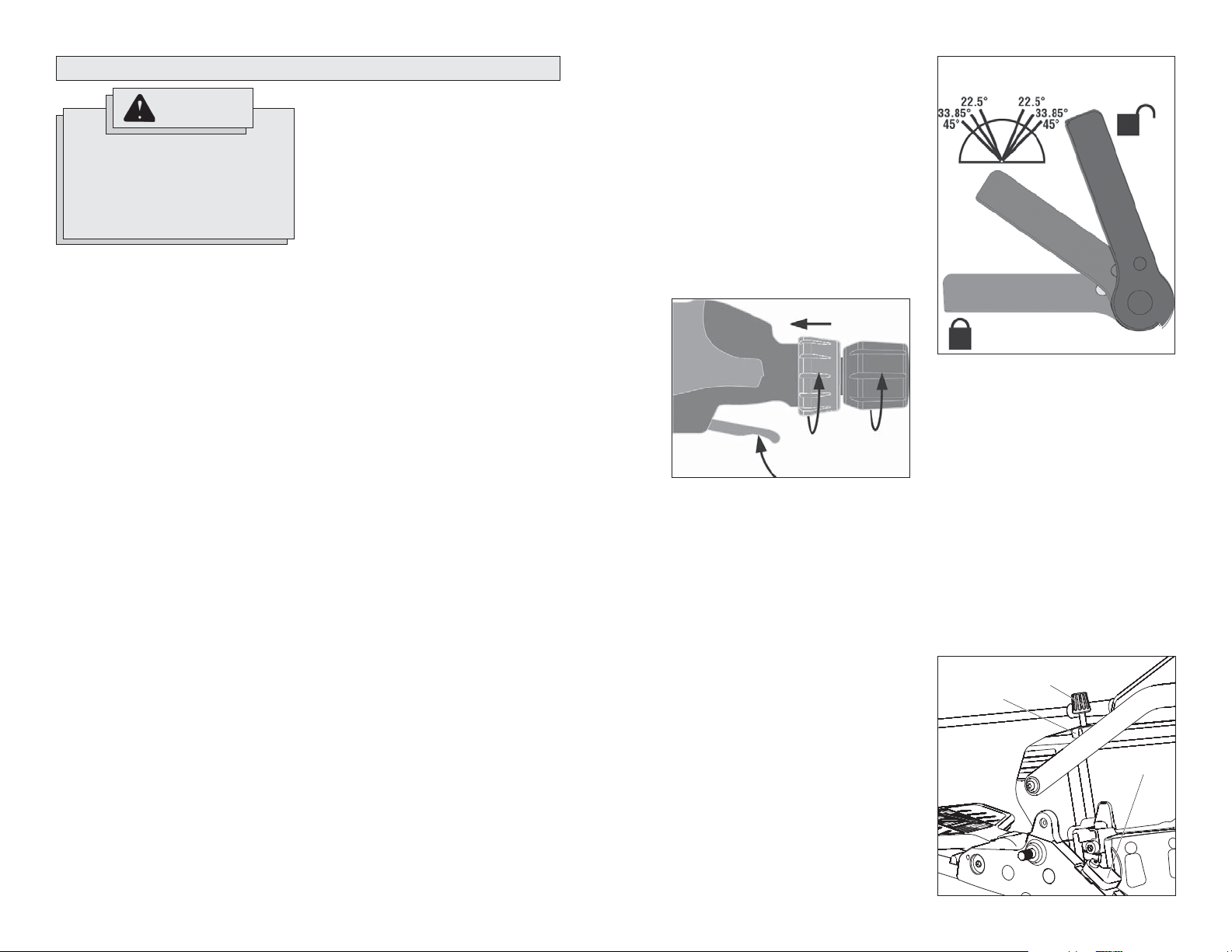
Dual Bevel Adjustment System
The Dual Bevel Adjustment System allows
for quick and accurate bevel adjustments
to either the Right or the Left. The bevel
angle can be set using detents (stops) for
the following commonly cut angles 0°, 22.5°,
33.85°, 45° Right and Left. The bevel mechanism also has several degrees of overtravel
beyond 45° on both the left and right.
TOOL ASSEMBLY
Electronic Feedback Control Circuit
The Electronic Feedback Control Circuit
(EFCC) helps improve the operation and
life of the tool. It allows the tool to maintain
constant speed and torque between no-load
and load conditions. The soft start reduces
the amount of torque reaction at startup to
the tool and the user. It gradually increases
the motor speed up from zero to the top
no-load speed.
Electric Brake
The electric brake engages when the trigger is released, causing the blade to stop
and allowing you to proceed with your work.
Generally the saw blade stops in four to fi ve
seconds. However, there may be a delay
between the time the trigger is released and
the time the brake engages. Occasionally
the brake may miss completely. If the brake
misses frequently, the saw needs servicing
by an authorized MILWAUKEE service station. The brake is not a substitute for the
guards, so it is essential to always wait for
the blade to stop completely before removing
the blade from the kerf.
Lights
The Milwaukee 6950-20 Miter Saw has two
high power lights positioned on either side of
the blade to illuminate the workpiece cutting
area so that it is easy to see blade approach
the cutting line. An ON / OFF switch for the
lights is conveniently located on the trigger
handle. The bulb is designed to provide
several years of service. Uses standard
bulb size GE 193.
Dust Management System
The Milwaukee 6955-20 Miter Saw dust
collection system uses a large dust chute on
both sides of the blade to capture and direct
dust to back of the saw. The saw comes with
a Dust Elbow and a Dust Bag that attach to
the back of the Dust Chute. The dust bag
has a zipper located on the bottom of the
bag that makes it easy to empty. When using
the saw on a stand, the dust bag zipper can
be left open to allow the waste to fall into a
waste container.
Carrying Handles
For ease of transporting, multiple carrying
handles are provided, one on each side of
the table and one on top of the saw head.
Always lock the saw head down when
transporting.
8 9
To reduce the risk of injury, always
unplug tool before attaching or
removing accessories or making
adjustments. Use only specifi cally
recommended accessories. Others
may be hazardous.
Adjusting the Miter Saw
The 6955-20 Miter Saw is fully adjusted at
the factory. If it is not accurate due to shipping and handling, please follow these steps
to accurately set up your saw. Once the saw
is properly adjusted, it should remain accurate under normal jobsite and transportation
conditions.
Squaring the Blade (90°) to the Fence
(0° Miter)
1. Unplug saw
2. Place a square against the fence and
blade and ensure that the square is not
touching blade teeth as this will cause
an inaccurate measurement.
3. Loosen the miter lock knob and move
the saw to the 0° miter position. Do not
tighten the lock knob.
4. If the saw blade is not exactly perpendicular to the fence, use the supplied
wrench to loosen the screws that hold
the miter scale to the base. Move the
scale left or right until the blade is perpendicular to the fence. Use the square
to verify that the blade is perpendicular
to the fence. Retighten the screws.
5. Loosen the miter pointer adjustment
screw and reposition the pointer the so
that it indicates exactly zero. Once the
pointer is properly positioned, retighten
the miter pointer adjustment screw.
Squaring the Blade (90°) to the Table
(0° Bevel)
1. Unplug saw
2. Place a square against the table and
blade and ensure that the square is not
touching blade teeth as this will cause
an inaccurate measurement.
3. Remove the 6 screws holding the dust
chute together.
WARNING
4. Move the bevel adjustment lever to the
middle position and wedge in a tool
(screw driver etc.) so the handle stay in
the middle position. Move the saw head
so that the bevel detent mechanism
locks into the 0° bevel detent.
5. Loosen 2 screws (T25) on the front of
the bevel arm, these screws are used
to clamp the detent body.
6. Using a T25 wrench you can adjust
the bevel setting of the blade-to-table.
Clockwise tilts blade to the right, counterclockwise tilts blade to the left.
7. When you have the blade set to the 0°
bevel, torque the 2 screws to 85-100 in
lbs.
8. Remove the tool used to wedge the
bevel adjustment lever.
9. Move the bevel adjustment lever to
"lock".
10. Reassemble the dust chute sides, tightening the 6 screws securely.
11. If necessary, loosen the left and right
bevel pointer adjustment screws and
reposition the pointers the so that they
indicates exactly zero. Once the pointers
are properly positioned, retighten the
bevel pointer adjustment screw.
Mounting the Miter Saw
To prevent the tool from sliding, falling or
tipping during operation, the saw can be
mounted to a supporting surface such as a
level, sturdy work table or bench. Position the
saw and workbench to allow adequate room
for cross-cutting long workpieces. To mount
the saw, insert fasteners through the holes
in the corners of the saw base.
Installing the Dust Bag
Use the dust bag to collect or divert sawdust.
Insert the dust elbow into the dust chute on
the back of the saw. Then, attach the dust
bag by hooking it onto the dust elbow. Always empty the dust bag before storing and
frequently during use.
Raising and Lowering the Saw Head
The saw head must be locked down for
transporting and storing the tool. The tool
is shipped with the saw head locked down.
To unlock it, press and hold down the saw
head and simultaneously pull out the lock
down pin. To lock the saw head, press and
hold down the saw head and then push in
the lock down pin.
Locking and Unlocking the Sliding
Mechanism
Always lock the sliding mechanism before
transporting or storing the saw. To unlock it,
loosen the slide rail lock by turning it counterclockwise. To lock it, tighten the slide rail
lock by turning it clockwise.
Lock-Off
There is a hole in the trigger through which a
padlock will fi t to lock the tool when it is not
in use. Use a padlock with a 1/4" shackle
and always unplug the tool before installing
it (padlock not supplied with tool).
Selecting the Correct Miter Saw Blade
Use only sliding miter saw blades with the
MILWAUKEE Sliding Dual Bevel Miter Saw .
Saw blades with a 0° hook angle or a negative hook angle work well for Sliding Miter
saws. A negative hook angle means that
teeth tip away from the direction of rotation,
and a 0° degree hook angle means that the
teeth are in line with the center of the blade.
A low or negative hook angle will slow the
feed rate and will also minimize the blade’s
tendency to “climb” the material being cut.
Installing and Changing Blades
Always use clean, sharp blades because dull
blades tend to overload the tool, bind and
cause pinching. Use only 12" blades rated at
least 5500 RPM.
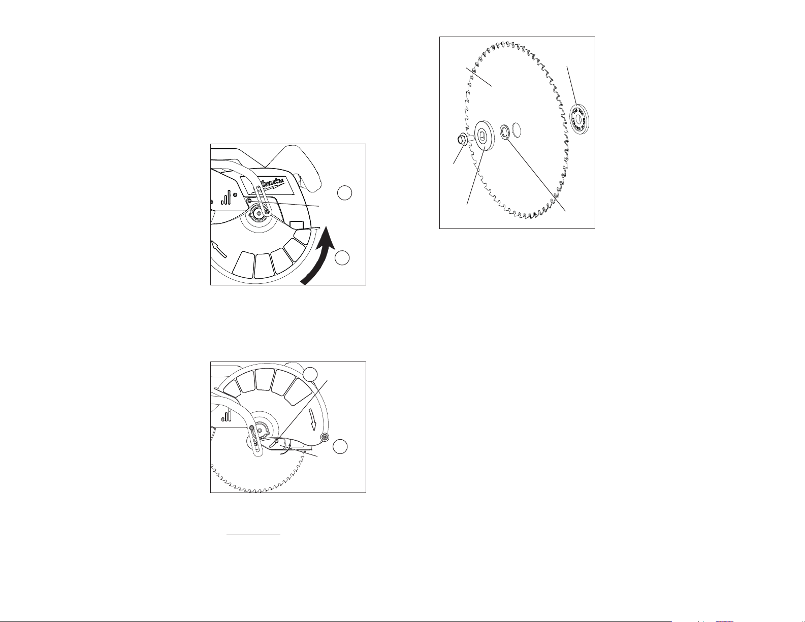
1. Unplug the tool.
2. With the saw head up, use the wrench
to loosen the guard bracket rear screw
1/4 turn using the wrench provided (1).
3. Raise the lower guard (2).
Fig. 1
1
Loosen guard
bracket rear
screw
2
Rotate lower
guard up
4. Loosen (do not remove) the guard
bracket front screw (3) until the guard
bracket can be raised to expose the
blade screw (4). Lower the lower guard
until it rests on the guard bracket front
screw. This will hold it up and out of the
way during the blade change.
Fig. 2
3
Loosen guard
front screw
bracket
4
Rotate guard
bracket up
Fig. 3
Blade
Inner fl ange
Blade
screw
Outer fl ange
Blade
washer
8. Install the inner blade fl ange as shown.
9. Insert the blade washer into the blade
arbor hole.
10. Match the arrow on the blade with the
arrow on the lower guard. Slide the
blade into the upper guard and onto the
spindle.
11. Install the outer blade fl ange.
12. Press in the spindle lock and rotate the
blade until the lock engages. Insert and
securely tighten the blade screw counterclockwise with the wrench.
13. Rotate the guard bracket into position
and securely tighten the two screws. Return the wrench to the wrench holder.
14. Lower the saw head and check the
clearance between the blade and the
adjustable kerf plates. Important: The
lower guard must move freely. The blade
should rotate freely (see "Adjusting the
Kerf Plates").
Adjusting the Kerf Plates
Kerf plates reduce tear-out and splintering
along the cut by providing edge support.
Because blades vary in width, adjust the kerf
plates with every blade change.
Never make a cut without the adjustable kerf
plates installed. The kerf plates can be set
at their maximum width to accommodate all
blade widths and bevel angles if tear-out and
splintering are not a concern.
1. Unplug the tool.
2. Install the blade to be used. Each time
the blade is changed, check to be
sure the kerf plates are adjusted
properly.
3. Set the bevel angle. Each time the bevel
is changed, check to be sure the kerf
plates are adjusted properly.
4. Loosen the six kerf plate adjusting
screws.
5. Lower the saw head to the full depth of
cut (the point where the saw head will
not lower any further).
6. Slide the kerf plates to the desired spacing and tighten the six screws.
7. Check to be sure the saw blade does not
contact the kerf plates before starting
the saw.
5. Press in the spindle lock and rotate the
spindle until the lock engages.
6. Use the wrench to loosen and remove the
left-hand thread blade screw clockwise.
7. Remove the outer blade fl ange, blade,
blade washer, and inner blade fl ange.
Wipe the fl anges, washer, and spindle
to remove dust and debris. Inspect the
parts for damage. Replace if needed.
10 11
OPERATION
WARNING
To reduce the risk of injury, wear
safety goggles or glasses with side
shields. Always wait for the blade
to stop completely and unplug the
tool before changing accessories or
making adjustments. Do not defeat
the guards.
Using Face Boards
(Zero Clearance Sub Fences)
There are face board mounting holes in the
fences for attaching face boards. Face boards
place distance between the fence and the
workpiece, providing improved support for
some workpieces. Workpiece splintering can
be reduced by using face boards. As the width
of the face board increases, the height of the
workpiece which can be cut increases slightly
(but the width capacity decreases slightly).
Similarly, if you place a face board on the saw
table and place a workpiece on top of the face
board, you can cut a workpiece with greater
width (but with less height).
Guards
The tool is shipped with both the upper and
lower guard installed. The lower guard should
cover the blade when the saw head is up and
it should move freely and open automatically
as the saw head is lowered into the workpiece.
If the lower guard appears loose, sticks, or if
it does not move to cover the blade when the
saw head is up, tighten the guard bracket
screws. If it still does not move freely, take
the saw to an authorized service center for
repairs. Do not attempt to open the guard
further than the automatic action permits.
Select the Workpiece Carefully
Be cautious of pitchy, knotty, wet or warped
workpieces. These materials are likely to create pinching conditions. Workpieces that bow
and pinch may result in kick back. Inspect
for and remove nails before cutting. Always
keep blades clean and sharp; otherwise the
blade produces a narrow kerf and is likely
to be pinched by the workpiece. This tool is
not recommended for cutting ferrous metals
such as iron and steel. See Applications for
a more complete list of materials.
4. To make a fi ne adjustment to the miter
angle:
A. Pull up and hold the detent lever .
Support the Workpiece Properly
Always support the workpiece during operation. Otherwise, the workpiece may pull up
and into the saw.
1. Use the Fence: Align the workpiece fl ush
against the fence to provide a straight
path for the saw blade. This will help
eliminate the tendency for the blade
teeth to bind. The fence can be used as
a support for miter, bevel and compound
cuts.
2. Use a clamp: Clamp the workpiece to
the fence or base with a C-clamp.
Support of Longer Workpieces
Longer workpieces need support along their
full length. If you are using the saw on a
level work bench, prop up the workpiece to
a height of 4-3/4" from the bottom of the saw
feet. There are also many aftermarket work
tables specifi cally designed for miter saws that
provide supports for all types of workpieces.
Adjusting the Miter Angle
The miter angle can be set using detents for
commonly cut angles, as well as fi nely adjust-
ed to any angle. Use the miter angle pointer
to adjust the turntable to any whole degree
across the miter range. The digital miter angle
readout shows the selected angle.
1. Loosen the miter angle lock knob.
2. To set the miter angle, pull up on the
detent lever and rotate the turntable
to the detent angle closest to the desired angle. The saw cuts miter angles
from 55° on the left to 60° on the right.
Detents are available at 0°, 15°, 22.5°
32.62°, 45°, and 60°.
3. Tighten the miter angle lock knob to use
the miter angle set at the detent before
making a cut.
12 13
B. Push the fi ne adjustment ring forward
until it locks to engage override.
C. Rotate the fi ne adjustment ring left
or right until the desired angle is
displayed on the digital miter angle
readout. ¼ turn = 1° change in miter
angle.
D. Tighten the miter angle lock knob
to secure the table before making a
cut.
E. Pull up on the detent lever to release
the fi ne adjustment ring.
Fig. 4
A
E
Adjusting the Bevel Angle
The bevel angle can be set using detents for
commonly cut angles, as well as adjusted
to any angle in between by using the bevel
angle scale. The bevel mechanism also has
several degrees of overtravel on both the left
and right.
1. Unplug the tool.
2. To adjust the bevel angle, place one
hand on the front handle for better control.
3. Using the other hand, lift the bevel adjustment lever:
A. To use pre-set detents, lift the
bevel adjustment lever half-way
up (until it "clicks") to move the
saw head left or right, with stops at
pre-set detents.
B. To freely move the head, lift the
bevel adjustment lever all the way
up to freely move the saw head
across the bevel range.
4. Pull or push the saw head to the desired
angle using the bevel angle scale.
5. Lock the bevel angle by pressing down
the bevel adjustment lever before making a cut.
B
C
D
Fig. 5
Detent Angles
Bevel
Adjustment
Lever
Lock
Adjusting the Depth of Cut
The depth of the cut can be adjusted for
groove or rabbet cuts.
1. Unplug the tool.
2. To set the depth of cut, swivel the depth
stop paw toward the front of the saw.
3. Lower the saw head to the desired depth
of cut.
4. Rotate the depth stop adjustment knob
until it contacts the paw. Lock in the
depth using the lock nut.
5. Plug in the tool and make a test cut to
verify the depth of cut is correct.
6. To remove the depth of cut limit, loosen
the lock nut by turning counterclockwise
and swivel the paw away from the front
of the saw.
Fig. 6
Lock nut
Knob
Unlock
Paw
Adjusting the Fences
1. Loosen the fence lock knobs.
2. The left side fence can slide side-to-side
to the desired position to allow for a left
bevel or left compound miter cuts.
3. The right side fence can be removed for
a right bevel or right compound miter
cuts by pulling the fence up.
4. Always position the fences properly for
maximum work support.
5. Tighten the fence lock knobs securely
before making a cut.
NOTE: If either fence has any movement
forward to backward, tighten the fence
set screw, located on the back of each
fence slot.
Lights
Use the on/off switch to turn on the turntable
lights before making a cut. Turn off the lights
when cutting is complete.
WARNING
To reduce the risk of injury, do not
rely on the brake as a safety feature.
Always wait until the blade stops
completely before allowing anything near the blade.
WARNING
To reduce the risk of injury, make
sure all adjustments are securely
locked before making a cut.
Starting and Stopping the Tool
Always hold the trigger handle fi rmly because
the starting and stopping action of the motor
may cause the handle to move up or down
slightly. Always secure the turntable by tightening the miter angle lock knob.
1. To start the motor, pull the trigger.
2. To stop the motor, release the trigger.
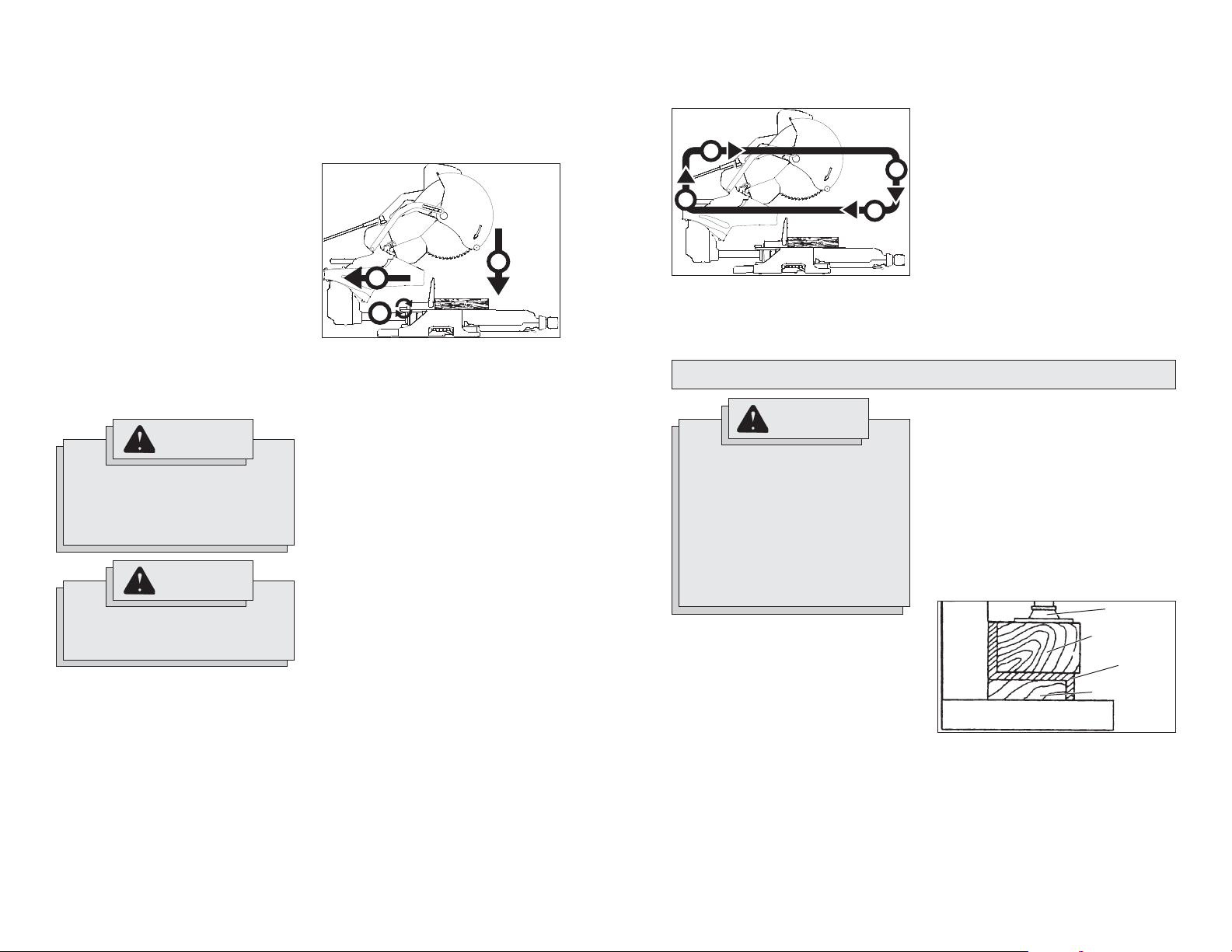
Making a Chop Cut
The sliding mechanism can be locked to use
the saw for chop cuts (cuts not requiring the
use of the slide mechanism). Cut workpieces
with chop cuts whenever possible. A chop
cut is always faster and easier to make than
a sliding cut.
Fig. 7
3
1
2
1. Slide the saw head all the way back
(1).
2. Tighten the slide rail lock (2).
3. Plug in the tool. Raise the saw head
completely.
4. Select the desired angles following the
steps in "Adjusting the Miter Angle" and
"Adjusting the Bevel Angle".
5. Place the workpiece on the turntable and
line up the cut.
6. Support the workpiece using any of
the methods described in "Support the
Workpiece Properly".
7. Start the motor. Wait a few seconds
for the blade to reach full speed. Then
gently lower the saw head into the workpiece all the way through the cut (3).
8. Always allow the saw to do the work.
Forcing the tool may stall or overheat
the motor.
9. After the cut is complete, release the
trigger and wait for the blade to stop
completely. Then gently raise the saw
head and remove the workpiece. Always
unplug the tool before retrieving loose
cut-off pieces from inside the guard
area.
Making a Sliding Cut
Wider workpieces can be cut using the sliding mechanism.
Fig. 8
1
2
4
1. Make sure that the slide rail lock is loose
and that the saw head moves freely
back and forth.
3
APPLICATIONS
WARNING
Do not cut stone, brick, concrete, or
ferrous metals (iron, steel, stainless
steel, or alloys of these metals) with
this saw.
Do not use abrasive wheels with this
saw.
Dust created by cutting these materials and/or using abrasive cut-off
wheels can jam the blade guard and
possibly cause personal injury.
Recommended Materials and
Applications
The following materials can be cut with the
slide compound miter saw. There are many
types of saw blades available. Always use
the proper blade for the particular material
and application.
Wood - solid wood, plywood, particle
board, MDF (medium density fi berboard),
HDF (high density fi berboard), melamine
laminated particle board, formica laminates, hardboard (masonite).
Plastics - PVC, CPVC, ABS, solid surfac-
ing materials (such as Corian®), and other
plastic materials.
Nonferrous Metals - aluminum, brass,
copper, and other non-ferrous materials.
2. Select the desired angle following the
steps in "Adjusting the Miter Angle" and
"Adjusting the Bevel Angle".
3. Place the workpiece on the turntable and
line up the cut.
4. Raise saw head and pull it out OVER
the workpiece WITHOUT cutting (1).
5. Start the motor. W ait a few seconds for
the blade to reach full speed.
6. Press down on saw head (2).
7. Push saw through the cut (3).
8. After the cut is complete, release the
trigger and wait for the blade to stop
completely. Then gently raise the saw
head (4) and remove the workpiece.
Always unplug the tool before retrieving loose cut-off pieces from inside the
guard area.
Cutting Non-Square Materials
Cutting Round (Cylindrical) Materials
"V" shaped blocks can be used to support
round materials like closet rod and plastic
pipe.
Aluminum Sash and Other Channel Type
and Materials
Aluminum sash material can be supported
with blocks to prevent it from deforming while
it is being cut.
Fig. 9
Fence
Base
Clamp
Wood support
block
Aluminum
material
Wood support
block
14 15
Miter
Range
0° to 55° Left
0° to 60° Right
0°, 15°, 22.5°, 31.62°, 45° Left
0°, 15°, 22.5°, 31.62°, 45° Right
Miter
Detents (Stops)
Base Molding
Capacity
6" at 0°
6" at 45° Left and Right
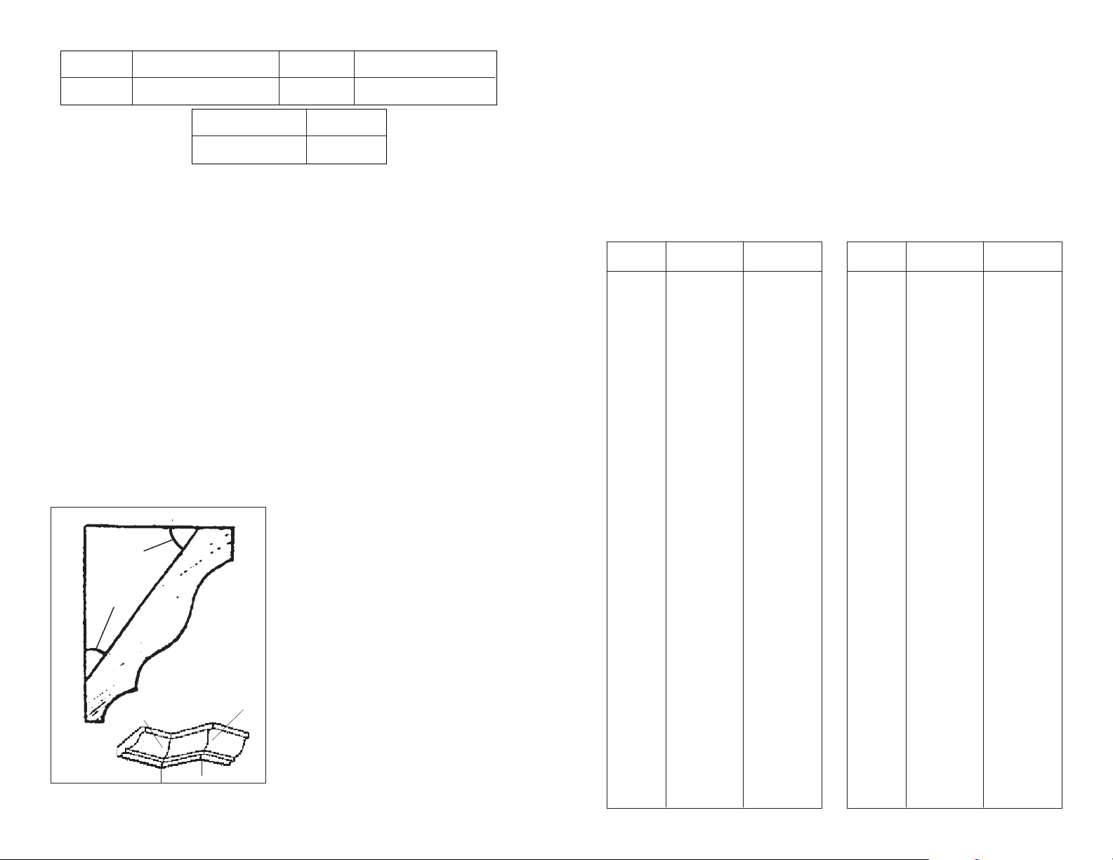
Two Methods for Cutting Crown Molding
The angles created on a piece of crown
molding that fi ts fl at against the ceiling and
wall will, when added together, equal 90°
(A + B = 90°).The most common crown
molding angles are :
52°/38°: A 52° angle against the ceiling (A)
and a 38° angle against the wall (B). The
miter saw has special miter settings at 31.6°
left and right and a bevel setting at 33.9° to
use when cutting 52°/ 38° crown molding fl at
on the miter saw table. These settings are
identifi ed with a diamond mark.
45°/45°: A 45° angle against the ceiling (A)
and a 45° angle against the wall (B). The
miter saw has special miter settings at 35.3°
left and right and a bevel setting at 30° to use
when cutting 45°/ 45° crown fl at on the miter
saw table. These settings are identifi ed with
a black circle.
NOTE: Even though all of these angles are
standard, rooms are very rarely constructed
so the corners are exactly 90°. Y ou will need
to “fi ne tune” these settings and make neces-
sary adjustments to the cutting angles.
Fig. 10
Ceiling
Angle A
Angle B
Wall
Inside
corner
Outside
corner
Bevel
Range
0° to 45° Left
0° to 48° Right
Nested Crown
Capacity
6-5/8"
0°, 22.5°, 33.85°, 45°, 48 Left
0°, 22.5°, 33.85°, 45°, 48 Right
Bevel
Detents (Stops)
Cutting Crown Molding Flat on the Miter
Saw Table
Standard (U.S.) crown molding with 45°
angles (set bevel angle to 0°)
Left side, inside corner
1. Top edge of molding against fence
2. Miter table set right 45
°
3. Save left end of cut
Right side, inside corner
1. Bottom edge of molding against fence
2. Miter table set left 45
°
3. Save left end of cut
The advantage of cutting crown molding fl at
on the table is that it is easier to secure the
molding at the correct cutting position. Also
larger pieces of crown molding may be cut
laying fl at on the miter saw table.
1. Set the bevel and miter angles using
the Crown Molding Miter Angles chart.
Tighten the miter lock knob and the
bevel lock knob.
2. Using the Positioning section below,
correctly positions the molding.
NOTE: Always make a test cut on scrap
material to confi rm all angles are correct.
3. Make the cut according to "Making a
Chop Cut".
Cutting Crown Molding Angled Against
the Fence (Nested – in position)
Always use a crown molding fence when
cutting crown molding angled against the
fence. When cutting crown molding angled
against the fence does not require bevel settings. Small changes in the miter angle can
be made without affecting the bevel angle.
When using this method the saw can be
quickly and easily adjusted for corners that
are not 90° (square).
Positioning
Standard (U.S.) crown molding with 52
and 38° angles (set bevel angle to 33.85°)
Left side, inside corner
1. Top edge of molding against fence
2. Miter table set right 31.62
°
3. Save left end of cut
Right side, inside corner
1. Bottom edge of molding against fence
2. Miter table set left 31.62
°
3. Save left end of cut
Left side, outside corner
1. Bottom edge of molding against fence
2. Miter table set left 31.62
°
3. Save right end of cut
Right side, outside corner
1. Top edge of molding against fence
2. Miter table set right 31.62
°
3. Save right end of cut
°
Crown Molding Miter Angles
Wall Angle
(B)
67
68
69
70
71
72
73
74
75
76
77
78
79
80
81
82
83
84
85
86
87
88
89
90
91
92
93
94
95
96
97
98
99
100
101
102
103
104
105
106
38˚ / 52˚
Miter/Bevel
42.93/41.08
42.39/40.79
41.85/40.50
41.32/40.20
40.79/39.90
40.28/39.61
39.76/39.30
39.25/39.00
38.74/38.69
38.24/38.39
37.74/38.08
37.24/37.76
36.75/37.45
36.27/37.13
35.79/36.81
35.31/36.49
34.83/36.17
34.36/35.85
33.90/35.52
33.43/35.19
32.97/34.86
32.52/34.53
32.07/34.20
31.62/33.86
31.17/33.53
30.73/33.19
30.30/32.85
29.86/32.51
29.43/32.17
29.00/31.82
28.58/31.48
28.16/31.13
27.74/30.78
27.32/30.43
26.91/30.08
26.50/29.73
26.09/29.38
25.69/29.02
25.29/28.67
24.78/28.31
45˚/45˚
Miter/Bevel
46.89/36.13
46.35/35.89
45.81/35.64
45.28/35.40
44.75/35.15
44.22/34.89
43.70/34.64
43.18/34.38
42.66/34.12
42.15/33.86
41.64/33.60
41.13/33.33
40.62/33.07
40.12/32.80
39.62/32.53
39.13/32.25
38.63/31.98
38.14/31.70
37.66/31.42
37.17/31.14
36.69/30.86
36.21/30.57
35.74/30.29
35.26/30.00
34.79/29.71
34.33/29.42
33.86/29.13
33.40/28.83
32.94/28.54
32.48/28.24
32.02/27.94
31.58/27.64
31.13/27.34
30.68/27.03
30.24/26.73
29.80/26.42
29.36/26.12
28.92/25.81
28.48/25.50
28.05/25.19
16 17
Left side, outside corner
1. Bottom edge of molding against fence
2. Miter table set left 45
°
3. Save right end of cut
Right side, outside corner
1. Top edge of molding against fence
2. Miter table set right 45
°
3. Save right end of cut
Wall
Angle (B)
107
108
109
110
111
112
113
114
115
116
117
118
119
120
121
122
123
124
125
126
127
128
129
130
131
132
133
134
135
136
137
138
139
140
141
142
143
144
145
146
38˚ / 52˚
Miter/Bevel
24.49/27.95
24.10/27.59
23.71/27.23
23.32/26.87
22.93/26.51
22.55/26.15
22.17/25.78
21.79/25.42
21.42/25.05
21.04/24.68
20.67/24.31
20.30/23.94
19.93/23.57
19.57/23.20
19.20/22.83
18.84/22.46
18.48/22.09
18.13/21.71
17.77/21.34
17.42/20.96
17.06/20.59
16.71/20.21
16.37/19.83
16.02/19.45
15.67/19.07
15.33/18.69
14.99/18.31
14.65/17.93
14.30/17.55
13.97/17.17
13.63/16.79
13.30/16.40
12.96/16.02
12.63/15.64
12.30/15.25
11.97/14.87
11.64/14.48
11.31/14.09
10.99/13.71
10.66/13.32
45˚/45˚
Miter/Bevel
27.62/24.87
27.19/24.56
26.77/24.24
26.34/23.93
25.92/23.61
25.50/23.29
25.08/22.97
24.66/22.65
24.25/22.33
23.84/22.01
23.43/21.68
23.02/21.36
22.61/21.03
22.21/20.70
21.80/20.38
21.40/20.05
21.00/19.72
20.61/19.39
20.21/19.06
19.81/18.72
19.42/18.39
19.03/18.06
18.64/17.72
18.25/17.39
17.86/17.05
17.48/16.71
17.09/16.38
16.71/16.04
16.32/15.70
15.94/15.36
15.56/15.02
15.19/14.68
14.81/14.34
14.43/14.00
14.06/13.65
13.68/13.31
13.31/12.97
12.94/12.62
12.57/12.28
12.20/11.93
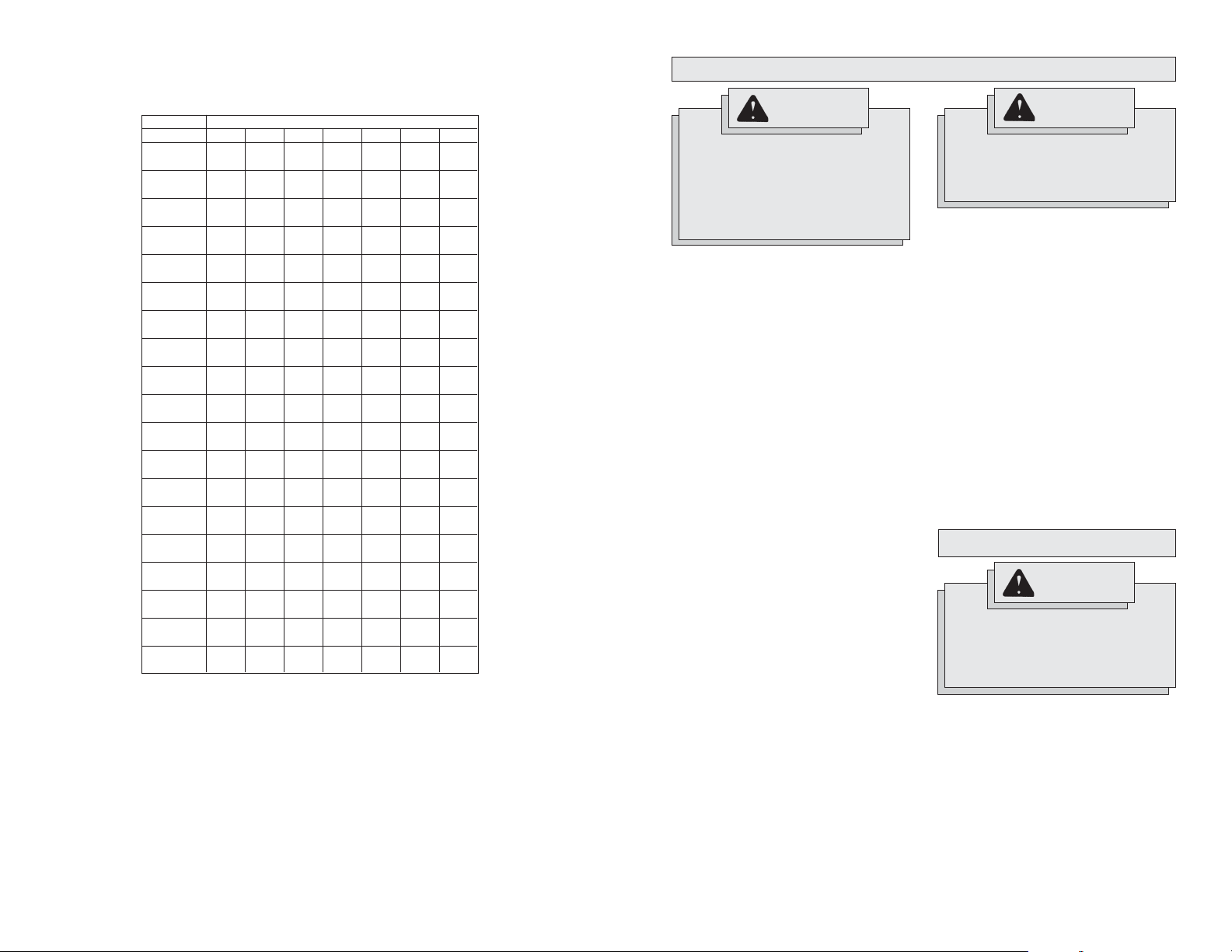
Cutting Compound Miters
The chart below identifi es miter and bevel settings for various types of compound miters. Always
make trial cuts in scrap material prior to making the cut in the workpiece.
Sides
7
89
22.50°
20.00°
0.00°
0.00°
22.42°
19.93°
1.91°
1.71°
19.72°
22.19°
3.40°
3.81°
19.37°
21.81°
5.08°
5.68°
21.27°
18.88°
7.52°
6.72°
18.26°
20.58°
8.31°
9.31°
17.50°
19.73°
9.85°
11.03°
16.60°
18.74°
11.31°
12.68°
15.58°
17.60°
12.70°
14.24°
14.43°
16.32°
14.00°
15.70°
13.17°
14.91°
15.19°
17.05°
11.79°
13.36°
16.27°
18.27°
10.31°
11.70°
17.23°
19.35°
8.74°
9.93°
18.06°
20.29°
7.10°
8.06°
18.75°
21.08°
5.38°
6.12°
19.29°
21.69°
3.62°
4.11°
19.68°
22.14°
1.82°
2.07°
19.92°
22.41°
0.00°
0.00°
20.00°
22.50°
10
18.00°
0.00°
17.94°
1.54°
17.74°
3.08°
17.42°
4.59°
16.98°
6.07°
16.41°
7.50°
15.72°
8.89°
14.90°
10.21°
13.98°
11.46°
12.94°
12.62°
11.80°
13.69°
10.56°
14.66°
9.23°
15.52°
7.82°
16.26°
6.34°
16.88°
4.81°
17.37°
3.23°
17.72°
1.62°
17.93°
0.00°
18.00°
10°
15°
20°
25°
30°
35°
40°
45°
50°
55°
60°
65°
70°
75°
80°
85°
90°
0°
5°
Pitch
Miter
Bevel
Miter
Bevel
Miter
Bevel
Miter
Bevel
Miter
Bevel
Miter
Bevel
Miter
Bevel
Miter
Bevel
Miter
Bevel
Miter
Bevel
Miter
Bevel
Miter
Bevel
Miter
Bevel
Miter
Bevel
Miter
Bevel
Miter
Bevel
Miter
Bevel
Miter
Bevel
Miter
Bevel
4
45.00°
0.00°
44.89°
3.53°
44.56°
7.05°
44.01°
10.55°
43.22°
14.00°
42.19°
17.39°
40.89°
20.70°
39.32°
23.93°
37.45°
27.03°
35.26°
30.00°
32.73°
32.80°
29.84°
35.40°
26.57°
37.76°
22.91°
39.86°
18.88°
41.64°
14.51°
43.08°
9.85°
44.14°
4.98°
44.78°
0.00°
45.00°
5
36.00°
0.00°
35.90°
2.94°
35.58°
5.86°
35.06°
8.75°
34.32°
11.60°
33.36°
14.38°
32.18°
17.09°
30.76°
19.70°
29.10°
22.20°
27.19°
24.56°
25.03°
26.76°
22.62°
28.78°
19.96°
30.60°
17.07°
32.19°
13.95°
33.53°
10.65°
34.59°
7.19°
35.37°
3.62°
35.84°
0.00°
36.00°
6
30.00°
0.00°
29.91°
2.50°
29.62°
4.98°
29.15°
7.44°
28.48°
9.85°
27.62°
12.20°
26.57°
14.48°
25.31°
16.67°
23.86°
18.75°
22.21°
20.70°
20.36°
22.52°
18.32°
24.18°
16.10°
25.66°
13.71°
26.95°
11.17°
28.02°
8.50°
28.88°
5.73°
29.50°
2.88°
29.87°
0.00°
30.00°
25.71°
0.00°
25.63°
2.17°
25.37°
4.32°
24.95°
6.45°
24.35°
8.53°
23.56°
10.57°
22.64°
12.53°
21.53°
14.41°
20.25°
16.19°
18.80°
17.87°
17.20°
19.41°
15.44°
20.82°
13.54°
22.07°
11.50°
23.16°
9.35°
24.06°
7.10°
24.78°
4.78°
25.30°
2.40°
25.61°
0.00°
25.71°
MAINTENANCE
WARNING
To reduce the risk of injury, always
unplug your tool before performing
any maintenance. Never disassemble
the tool or try to do any rewiring on
the tool's electrical system. Contact a
MILWAUKEE service facility for ALL
repairs.
Maintaining Tools
Keep your tool in good repair by adopting a
regular maintenance program. Before use,
examine the general condition of your tool.
Inspect guards, switches, tool cord set and
extension cord for damage. Check for loose
screws, misalignment, binding of moving
parts, improper mounting, broken parts and
any other condition that may affect its safe
operation. If abnormal noise or vibration occurs, turn the tool off immediately and have
the problem corrected before further use.
Do not use a damaged tool. Tag damaged
tools “DO NOT USE” until repaired (see
“Repairs”).
Under normal conditions, re-lubrication is
not necessary until the motor brushes need
to be replaced. After six months to one year ,
depending on use, return your tool to the
nearest MILWAUKEE service facility for the
following:
• Lubrication
• Brush inspection and replacement
• Mechanical inspection and cleaning
(gears, spindles, bearings, housing,
etc.)
• Electrical inspection (switch, cord,
armature, etc.)
• T esting to assure proper mechanical and
electrical operation
WARNING
To reduce the risk of injury, electric
shock and damage to the tool, never
immerse your tool in liquid or allow a
liquid to fl ow inside the tool.
Cleaning
Clean dust and debris from vents. Keep
the tool handles clean, dry and free of oil
or grease. Use only mild soap and a damp
cloth to clean your tool since certain cleaning
agents and solvents are harmful to plastics
and other insulated parts. Some of these
include: gasoline, turpentine, lacquer thinner,
paint thinner, chlorinated cleaning solvents,
ammonia and household detergents containing ammonia. Never use fl ammable or
combustible solvents around tools.
Repairs
If your tool is damaged, return the entire tool
to the nearest service center.
ACCESSORIES
WARNING
To reduce the risk of injury, always
unplug the tool before attaching or
removing accessories. Use only specifi cally recommended accessories.
Others may be hazardous.
For a complete listing of accessories refer to
your MILWAUKEE Electric Tool catalog or go
on-line to www.milwaukeetool.com. To obtain
a catalog, contact your local distributor or a
service center.
18 19
 Loading...