

OPERATOR'S MANUAL
MANUEL de L'UTILISATEUR
MANUAL del OPERADOR
Cat. No. / No de cat.
6065, 6065-6, 6066, 6066-6, 6072, 6078
SANDERS
PONCEUSES
LIJADORAS
WARNING To reduce the risk of injury, user must read and understand operator's manual.
AVERTISSEMENT An de réduire le risque de blessures, l'utilisateur doit lire et bien
comprendre le manuel.
ADVERTENCIA Para reducir el riesgo de lesiones, el usuario debe leer y entender el manual.

2

GENERAL POWER TOOL
WARNING
SAFETY WARNINGS
Read all safety warnings, instruc-
tions provided with this power tool. Failure to follow
all instructions listed below may result in electric shock,
re and/or serious injury. Save all warnings and instructions for future reference. The term "power tool"
in the warnings refers to your mains-operated (corded)
power tool or battery-operated (cordless) power tool.
tions, illustrations and specica-
WORK AREA SAFETY
• Keep work area clean and well lit. Cluttered or dark
areas invite accidents.
• Do not operate power tools in explosive atmo-
spheres, such as in the presence of ammable
liquids, gases or dust. Power tools create sparks
which may ignite the dust or fumes.
• Keep children and bystanders away while operat-
ing a power tool. Distractions can cause you to lose
control.
ELECTRICAL SAFETY
• Power tool plugs must match the outlet. Never
modify the plug in any way. Do not use any adapter
plugs with earthed (grounded) power tools. Un-
modied plugs and matching outlets will reduce risk
of electric shock.
• Avoid body contact with earthed or grounded
surfaces, such as pipes, radiators, ranges and
refrigerators. There is an increased risk of electric
shock if your body is earthed or grounded.
• Do not expose power tools to rain or wet conditions. Water entering a power tool will increase the
risk of electric shock.
• Do not abuse the cord. Never use the cord for car-
rying, pulling or unplugging the power tool. Keep
cord away from heat, oil, sharp edges or moving
parts. Damaged or entangled cords increase the risk
of electric shock.
• When operating a power tool outdoors, use an
extension cord suitable for outdoor use. Use of
a cord suitable for outdoor use reduces the risk of
electric shock.
• If operating a power tool in a damp location is
unavoidable, use a ground fault circuit interrupter
(GFCI) protected supply. Use of an GFCI reduces
the risk of electric shock.
PERSONAL SAFETY
• Stay alert, watch what you are doing and use common sense when operating a power tool. Do not
use a power tool while you are tired or under the
inuence of drugs, alcohol or medication. A moment of inattention while operating power tools may
result in serious personal injury.
• Use personal protective equipment. Always wear
eye protection. Protective equipment such as a dust
mask, non-skid safety shoes, hard hat or hearing
protection used for appropriate conditions will reduce
personal injuries.
• Prevent unintentional starting. Ensure the switch
is in the o-position before connecting to power
source and/or battery pack, picking up or carrying
the tool. Carrying power tools with your nger on the
switch or energizing power tools that have the switch
on invites accidents.
• Remove any adjusting key or wrench before
turning the power tool on. A wrench or a key left at-
tached to a rotating part of the power tool may result
in personal injury.
• Do not overreach. Keep proper footing and balance
at all times. This enables better control of the power
tool in unexpected situations.
• Dress properly. Do not wear loose clothing or
jewelry. Keep your hair and clothing away from
moving parts. Loose clothes, jewelry or long hair can
be caught in moving parts.
• If devices are provided for the connection of dust
extraction and collection facilities, ensure these
are connected and properly used. Use of dust col-
lection can reduce dust-related hazards.
• Do not let familiarity gained from frequent use of
tools allow you to become complacent and ignore
tool safety principles. A careless action can cause
severe injury within a fraction of a second.
POWER TOOL USE AND CARE
• Do not force the power tool. Use the correct power
tool for your application. The correct power tool will
do the job better and safer at the rate for which it was
designed.
• Do not use the power tool if the switch does not turn
it on and o. Any power tool that cannot be controlled
with the switch is dangerous and must be repaired.
• Disconnect the plug from the power source and/
or remove the battery pack, if detachable, from
the power tool before making any adjustments,
changing accessories, or storing power tools.
Such preventive safety measures reduce the risk of
starting the power tool accidentally.
• Store idle power tools out of the reach of children
and do not allow persons unfamiliar with the
power tool or these instructions to operate the
power tool. Power tools are dangerous in the hands
of untrained users.
• Maintain power tools and accessories. Check for
misalignment or binding of moving parts, breakage of parts and any other condition that may affect the power tool’s operation. If damaged, have
the power tool repaired before use. Many accidents
are caused by poorly maintained power tools.
• Keep cutting tools sharp and clean. Properly maintained cutting tools with sharp cutting edges are less
likely to bind and are easier to control.
• Use the power tool, accessories and tool bits etc.
in accordance with these instructions, taking into
account the working conditions and the work to
be performed. Use of the power tool for operations
dierent from those intended could result in a hazardous situation.
• Keep handles and grasping surfaces dry, clean
and free from oil and grease. Slippery handles and
grasping surfaces do not allow for safe handling and
control of the tool in unexpected situations.
SERVICE
• Have your power tool serviced by a qualied repair
person using only identical replacement parts.
This will ensure that the safety of the power tool is
maintained.
SPECIFIC SAFETY RULES FOR
SANDERS
Safety Warnings Common for Sanding Operations:
• This power tool is intended to function as a sander.
Read all safety warnings, instructions, illustrations
and specications provided with this power tool.
Failure to follow all instructions listed below may result
in electric shock, re and/or serious injury.
• Operations such as grinding, wire brushing,
polishing or cutting-o are not recommended to
be performed with this power tool. Operations for
3

which the power tool was not designed may create a
WARNING
hazard and cause personal injury.
• Do not use accessories which are not specically
designed and recommended by the tool manufac-
turer. Just because the accessory can be attached to
your power tool, it does not assure safe operation.
• The rated speed of the accessory must be at least
equal to the maximum speed marked on the power
tool. Accessories running faster than their rated speed
can break and y apart.
• The outside diameter and the thickness of your
accessory must be within the capacity rating of
your power tool. Incorrectly sized accessories cannot
be adequately guarded or controlled.
• Threaded mounting of accessories must match the
grinder spindle thread. For accessories mounted
by anges, the arbour hole of the accessory must
t the locating diameter of the ange. Accessories
that do not match the mounting hardware of the power
tool will run out of balance, vibrate excessively and
may cause loss of control.
• Do not use a damaged accessory. Before each use
inspect the accessory such as abrasive wheels for
chips and cracks, backing pad for cracks, tear or
excess wear, wire brush for loose or cracked wires.
If power tool or accessory is dropped, inspect for
damage or install an undamaged accessory. After
inspecting and installing an accessory, position
yourself and bystanders away from the plane of the
rotating accessory and run the power tool at maximum no-load speed for one minute. Damaged ac-
cessories will normally break apart during this test time.
• Wear personal protective equipment. Depending
on application, use face shield, safety goggles or
safety glasses. As appropriate, wear dust mask,
hearing protectors, gloves and workshop apron
capable of stopping small abrasive or workpiece
fragments. The eye protection must be capable of
stopping ying debris generated by various operations.
The dust mask or respirator must be capable of ltrating
particles generated by your operation. Prolonged exposure to high intensity noise may cause hearing loss.
• Keep bystanders a safe distance away from work
area. Anyone entering the work area must wear
personal protective equipment. Fragments of
workpiece or of a broken accessory may y away and
cause injury beyond immediate area of operation.
• Hold the power tool by insulated gripping sur-
faces only, when performing an operation where
the cutting tool may contact hidden wiring or its
own cord. Contact with a "live" wire may also make
exposed metal parts of the power tool "live" and could
give the operator an electric shock.
• Position the cord clear of the spinning accessory.
If you lose control, the cord may be cut or snagged
and your hand or arm may be pulled into the spinning
accessory.
• Never lay the power tool down until the accessory
has come to a complete stop. The spinning acces-
sory may grab the surface and pull the power tool out
of your control.
• Do not run the power tool while carrying it at your side.
Accidental contact with the spinning accessory could
snag your clothing, pulling the accessory into your body.
• Regularly clean the power tool’s air vents. The
motor’s fan will draw the dust inside the housing and
excessive accumulation of powdered metal may cause
electrical hazards.
• Do not operate the power tool near ammable
materials. Sparks could ignite these materials.
• Do not use accessories that require liquid cool-
ants. Using water or other liquid coolants may result
in electrocution or shock.
Kickback and Related Warnings
Kickback is a sudden reaction to a pinched or snagged
rotating wheel, backing pad, brush or any other acces-
sory. Pinching or snagging causes rapid stalling of the
rotating accessory which in turn causes the uncontrolled power tool to be forced in the direction opposite
of the accessory’s rotation at the point of the binding.
For example, if an abrasive wheel is snagged or
pinched by the workpiece, the edge of the wheel that
is entering into the pinch point can dig into the surface
of the material causing the wheel to climb out or kick
out. The wheel may either jump toward or away from
the operator, depending on direction of the wheel’s
movement at the point of pinching. Abrasive wheels
may also break under these conditions.
Kickback is the result of power tool misuse and/or in-
correct operating procedures or conditions and can be
avoided by taking proper precautions as given below.
• Maintain a rm grip on the power tool and position
your body and arm to allow you to resist kickback
forces. Always use auxiliary handle, if provided,
for maximum control over kickback or torque reaction during start-up. The operator can control torque
reactions or kickback forces, if proper precautions are
taken.
• Never place your hand near the rotating accessory.
Accessory may kickback over your hand.
• Do not position your body in the area where power
tool will move if kickback occurs. Kickback will
propel the tool in direction opposite to the wheel’s
movement at the point of snagging.
• Use special care when working corners, sharp
edges etc. Avoid bouncing and snagging the accessory. Corners, sharp edges or bouncing have a
tendency to snag the rotating accessory and cause
loss of control or kickback.
• Do not attach a saw chain woodcarving blade or
toothed saw blade. Such blades create frequent
kickback and loss of control.
Safety Warnings Specic for Sanding Operations:
• Do not use excessively oversized sanding disc
paper. Follow manufacturers recommendations,
when selecting sanding paper. Larger sanding
paper extending beyond the sanding pad presents a
laceration hazard and may cause snagging, tearing
of the disc or kickback.
Additional Safety Warnings
• Maintain labels and nameplates. These carry im-
portant information. If unreadable or missing, contact
a MILWAUKEE service facility for a free replacement.
•
construction activities contains chemicals known to
cause cancer, birth defects or other reproductive harm.
Some examples of these chemicals are:
• lead from lead-based paint
• crystalline silica from bricks and cement and other
masonry products, and
• arsenic and chromium from chemically-treated lumber.
Your risk from these exposures varies, depending on
how often you do this type of work. To reduce your
exposure to these chemicals: work in a well ventilated
area, and work with approved safety equipment, such
as those dust masks that are specially designed to
lter out microscopic particles.
4
Some dust created by power sanding,
sawing, grinding, drilling, and other
C
US
GROUNDING
WARNING
Improperly connecting the grounding wire can result in the risk of
electric shock. Check with a qualied electrician
if you are in doubt as to whether the outlet is
properly grounded. Do not modify the plug provided with the tool. Never remove the grounding
prong from the plug. Do not use the tool if the
cord or plug is damaged. If damaged, have it
repaired by a MILWAUKEE service facility before
use. If the plug will not t the outlet, have a
proper outlet installed by a qualied electrician.
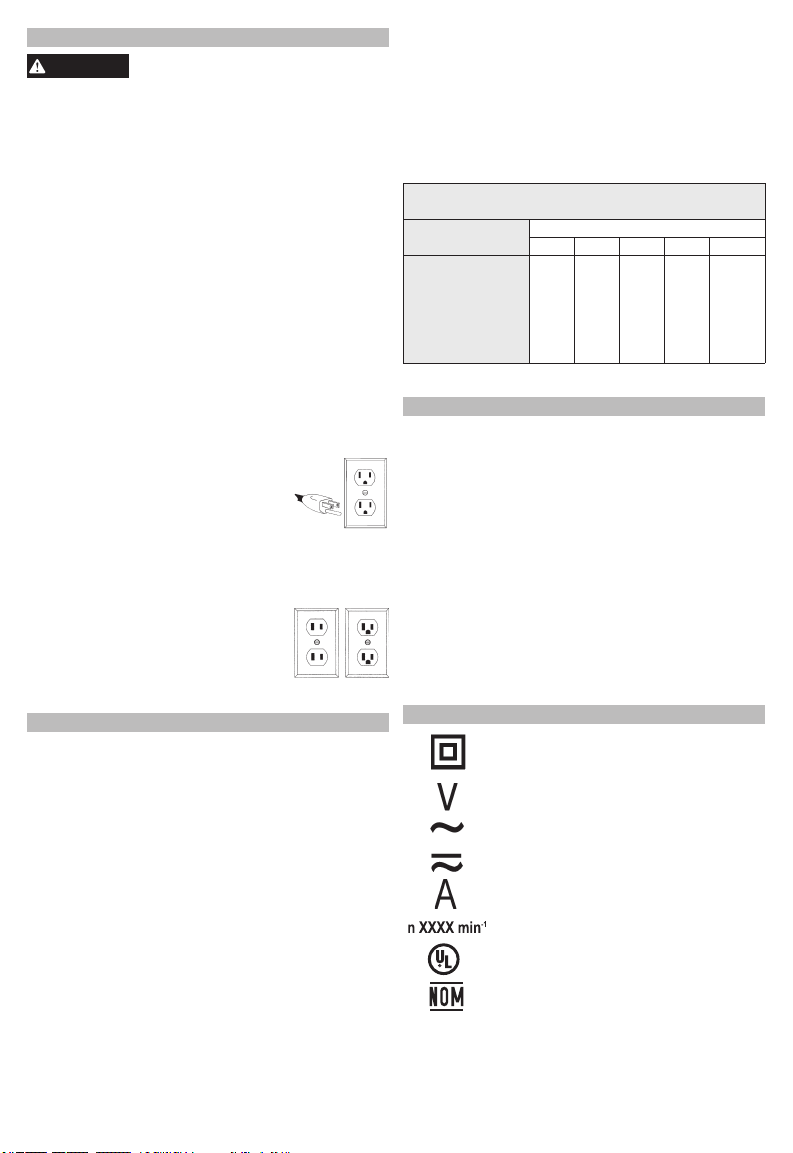
Grounded Tools (Three-Prong Plugs)
Tools marked “Grounding Required” have a three
wire cord and three prong grounding plug. The plug
must be connected to a properly grounded outlet
(See Figure A). If the tool should electrically malfunction or break down, grounding provides a low
resistance path to carry electricity away from the
user, reducing the risk of electric shock.
The grounding prong in the plug is connected through
the green wire inside the cord to the grounding
system in the tool. The green wire in the cord must
be the only wire connected to the tool's grounding
system and must never be attached to an electrically
“live” terminal.
Your tool must be plugged into an appropriate outlet, properly installed and
grounded in accordance with all codes
and ordinances. The plug and outlet
should look like those in Figure A.
Double Insulated Tools (Two-Prong Plugs)
Tools marked “Double Insulated” do not require
grounding. They have a special double insulation
system which satisfies OSHA requirements and
complies with the applicable standards
of Underwriters Laboratories, Inc., the
Canadian Standard Association and
the National Electrical Code. Double
Insulated tools may be used in either
of the 120 volt outlets shown in Figures
B and C.
Fig. A
Fig. B
Fig. C
EXTENSION CORDS
Grounded tools require a three wire extension
cord. Double insulated tools can use either a two
or three wire extension cord. As the distance from
the supply outlet increases, you must use a heavier
gauge extension cord. Using extension cords with
inadequately sized wire causes a serious drop in
voltage, resulting in loss of power and possible tool
damage. Refer to the table shown to determine the
required minimum wire size.
The smaller the gauge number of the wire, the greater
the capacity of the cord. For example, a 14 gauge
cord can carry a higher current than a 16 gauge cord.
When using more than one extension cord to make
up the total length, be sure each cord contains at
least the minimum wire size required. If you are using
one extension cord for more than one tool, add the
nameplate amperes and use the sum to determine
the required minimum wire size.
Guidelines for Using Extension Cords
• If you are using an extension cord outdoors, be sure
it is marked with the sux “W-A” (“W” in Canada) to
indicate that it is acceptable for outdoor use.
• Be sure your extension cord is properly wired and in
good electrical condition. Always replace a damaged
extension cord or have it repaired by a qualied
person before using it.
• Protect your extension cords from sharp objects,
excessive heat and damp or wet areas.
Recommended Minimum Wire Gauge
For Extension Cords*
Extension Cord Length
Nameplate Amps
0 - 2.0
2.1 - 3.4
3.5 - 5.0
5.1 - 7.0
7.1 - 12.0
12.1 - 16.0
16.1 - 20.0
* Based on limiting the line voltage drop to ve volts at 150%
of the rated amperes.
25' 50' 75' 100' 150'
18
18
18
18
18
18
18
16
14
12
18
18
16
14
12
10
18
16
14
12
10
--
16
14
12
10
16
14
12
12
--
--
--
--
--
SPECIFICATIONS
Spindle Size................................................5/8"-11"
Max Capacity ...........................................7"/9"x1/4"
Cat. No. ....................................... 6065 and 6065-6
Volts .......................................................120 AC/DC
Amps ...................................................................15
No Load RPM ..................................................6000
Cat. No. ....................................... 6066 and 6066-6
Volts .......................................................120 AC/DC
Amps ...................................................................15
No Load RPM ..................................................6600
Cat. No. ...........................................................6072
Volts .......................................................120 AC/DC
Amps ...................................................................13
No Load RPM ..................................................6000
Cat. No. ...........................................................6078
Volts .............................................................120 AC
Amps ...................................................................13
No Load RPM ............................................ 0 - 6600
SYMBOLOGY
Double Insulated
Volts
Alternating Current/Direct Current
Amps
Approval Mark for Mexico
Alternating Current
Rated Revolutions per Minute (RPM)
UL Listing Mark for Canada and U.S.
5
FUNCTIONAL DESCRIPTION
WARNING
WARNING
4
5
3
2
1
4
ASSEMBLY
To reduce the risk of injury, always
removing accessories.
6
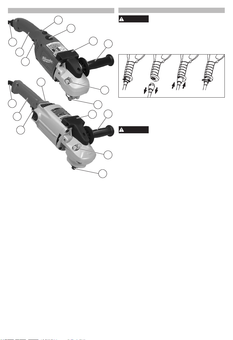
Removing and Replacing Quik-Lok
7
MILWAUKEE's exclusive Quik-Lok® Cords provide
instant eld replacement or substitution.
8
unplug tool before changing or
®
(Select Models)
Cords
3
2
1
1. Trigger
2 Handle
3. Cord
4. Trigger lock
(some models)
5. Dial speed control
(6078 only)
6. Tool rest
7. Side handle
8. Spindle lock button
9. Spindle
9
6
1. To remove the Quik-Lok® Cord, turn the cord nut
1/4 turn to the left and pull it out.
2. To replace the Quik-Lok® Cord, align the connector
7
keyways and push the connector in as far as it will
go. Turn the cord nut 1/4 turn to the right to lock.
To reduce the risk of injury, always
tool. Hold securely.
The side handle may be installed on either side of
the gear case. Position the side handle in the loca-
8
tion which oers best control and guard protection.
To install, thread side handle into side handle socket
and tighten securely.
9
Use sanding discs and accessories that are:
• correct size as written on tool’s nameplate.
• rated at or above the RPM listed on the tool’s name-
plate.
• correct accessory, wheel type and grit for the job.
Select the correct type of sanding disc for your job.
Generally, use 24 or 36 grit for heavy stock removal;
50, 60, or 80 grit for medium stock removal and 120
grit for nishing. Always begin with a coarse grit, using successively ner grits to obtain the desired nish.
•Aluminum Oxide: For fast cutting, general purpose
discs for most metal jobs. Best for cold-rolled steel,
stainless steel or metals requiring tough, fast cutting,
long lasting abrasives.
•Aluminum Zirconia Bi-Cut: Unique grit pattern is
arranged in clusters for faster stock removal and
cleaning. Ideal for removing paint from cars, boats,
etc. without clogging.
•Ceramic: Lasts up to 3 times longer than Aluminum
Oxide Discs. For general metal working. Ideal for
tough jobs.
use a side handle when using this
Installing Side Handle
Sanding Disc Selection
6
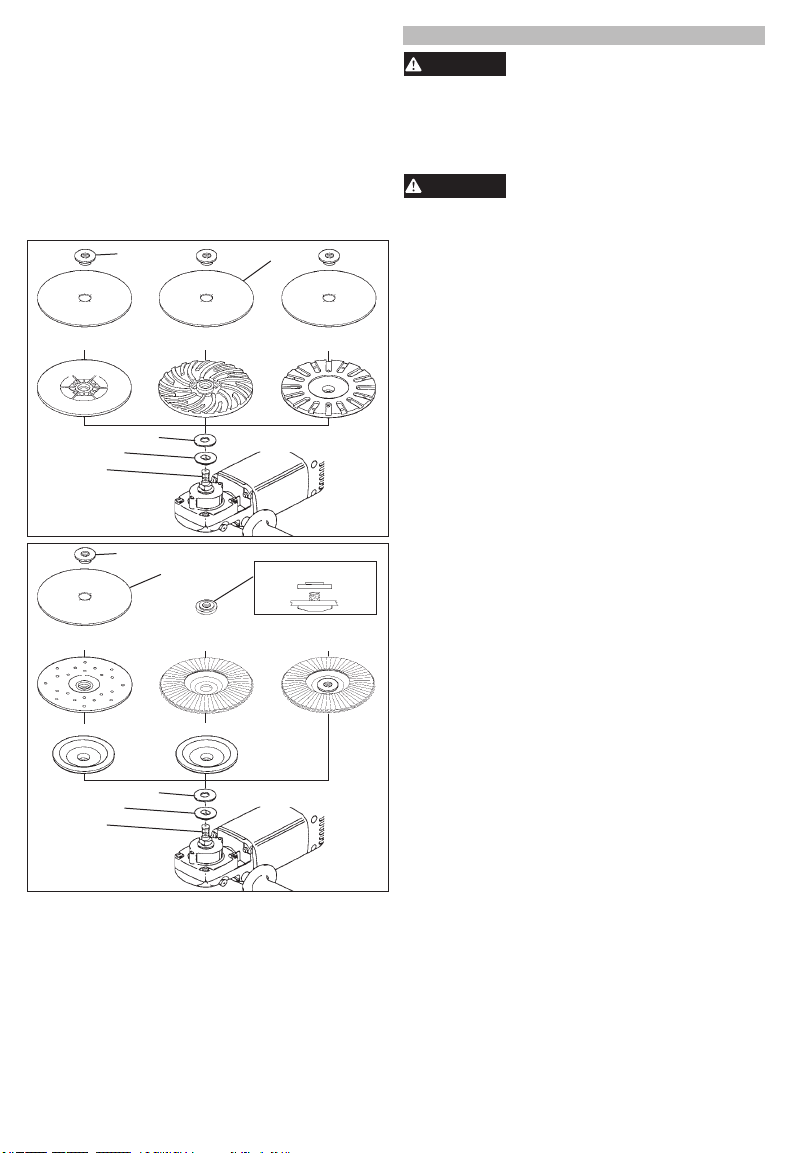
Installing Backing Pad and Sanding Discs
WARNING
WARNING
1. Unplug tool and place it upside down on a level
surface as shown. WARNING! Always unplug
tool before changing or removing accessories.
Remove any accessories from spindle.
2. Thread ange and nylon washer onto spindle.
Attach backing pad and sanding disc as shown.
NOTE: When installing ap disc without hub, position ap disc nut as shown.
3. To tighten, press in the spindle lock button while
turning disc nut clockwise.
4. To remove sanding disc and backing pad, unplug
tool and reverse procedure.
Polypropylene
backing pad
Nylon washer
Flange
Spindle
Phenolic
backing pad
Rubber pad
Nylon washer
Flange
Spindle
Disc nut
backing pad
Disc nut
Sanding disc
without hub
Type 27 ange
Spiral
Flap disk
Sanding disc
Rubber
backing pad
Flap disc nut position
Flap disk
with hub
OPERATION
To reduce the risk of injury, always
with side shields. Never grind without proper
safety equipment.
Starting and Stopping the Motor
1. To start the tool, pull the trigger.
2. To stop the tool, release the trigger.
provided before and during use.
To reduce the risk of injury or damage to the
tool, do not use the spindle lock button to stop
the spindle while the tool is in use or is coasting
after shut-o.
Locking the Trigger (Select Models)
The lock button holds the trigger in the ON position
for continuous use.
1. To lock the trigger on, hold in the lock-on button
while pulling the trigger. Release the trigger.
2. To unlock the trigger, pull the trigger and release.
The lock-on button will pop out.
Cat. No. 6078 has a dial speed control and variable
speed trigger switch. The maximum speed may be
preset using the speed control dial and the speed
may be varied by the trigger switch. Speed control
dial settings range from 1 to 5. Lower numbers
correspond to lower speeds and higher numbers
correspond to higher speeds. Use the setting that
best suits the work.
To control the speed, set the dial to the desired
number. Then, pull the trigger. Increase or decrease
pressure on the trigger to vary the speed. To stop the
tool, release the trigger.
1. If you have just installed an accessory or are
beginning a period of work, test the wheel by
letting it spin for one minute before applying it to
the workpiece. WARNING! Never use a grinding
wheel that has been dropped. Out-of-balance or
damaged accessories can mar workpiece, damage the tool, and cause stress that may cause
accessory failure.
2. Use a clamp, vise or other practical means to hold
your work, freeing both hands to control the tool.
3. WARNING! Hold tool securely with both hands.
Start the tool.
4. Allow accessory to come to full speed before
beginning work.
5. Control pressure and surface contact between
accessory and workpiece. WARNING! Never
bang grinding wheel onto work.Too much pressure
causes accessory failure or slows speed.
6. When nished, turn o the tool and make sure it
comes to a complete stop before laying it down.
wear safety goggles or glasses
Always hold the tool rmly with
both hands using the handles
Using the Dial Speed Control
(Cat. No. 6078 only)
General Operation
7
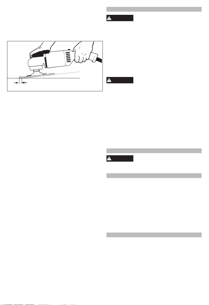
Hold tool at 5° to 15° angle to ensure proper sanding
WARNING
WARNING
WARNING
pressure and control. Too great an angle will result
in too much pressure and could cause excessive
wear to the disc and workpiece. Too small an angle
will reduce control.
Use long, sweeping, side to side strokes, advancing
forward to produce the desired nish.
For best results, use only this portion of the disc.
Cross Sanding - When nishing a surface that
has been prepared by a coarse disc or wheel, sand
at right angles to the strokes made by the coarser
disc. Finishing marks left from previous sanding are
easily seen and removed for a uniform nish. Failure
to cross sand when changing from a coarse disc to
a nishing disc may result in deep scratches and
circular marks.
Removing Welds or Hammer Marks - When removing welds or hammer marks, limit coarse sanding to
the immediate area. Use successively ner grits to
smooth surface.
Finishing Metal - Constantly move across the sur-
face. Work faster on curved surfaces where contact
areas are smaller and pressure is greater. Flat areas
may appear at the end of the stroke when pressure
is too heavy. Ease up on pressure at end of each
stroke and when reversing strokes.
Deep scratches and circular marks can result from:
• Using too coarse a grit
• Using a partially glazed disc
• Dirt or loose metal on the workpiece
• Failure to sand across the grain when changing from
coarse to nishing discs
• Failure to use closed coated discs to reduce the
problem of grains working loose and scratching the
workpiece
Bluish discoloration of metal surface indicates:
• Excessive heat caused by circular motion in a small area
• Excessive pressure
• Use of worn out or glazed discs
Using Sanding Discs
Hold at a
5° to 15°
angle
Troubleshooting
MAINTENANCE
To reduce the risk of injury, always
any maintenance. Never disassemble the tool.
Contact a MILWAUKEE service facility for ALL
repairs.
Keep your tool in good repair by adopting a regular
maintenance program. Inspect your tool for issues
such as undue noise, misalignment or binding of
moving parts, breakage of parts, or any other condi-
tion that may aect the tool operation. Return the tool
to a MILWAUKEE service facility for repair. After six
months to one year, depending on use, return the
tool to a MILWAUKEE service facility for inspection.
never immerse your tool in liquid or allow a liquid
to ow inside it.
Clean dust and debris from vents. Keep handles
clean, dry and free of oil or grease. Use only mild
soap and a damp cloth to clean, since certain cleaning agents and solvents are harmful to plastics
and other insulated parts. Some of these include
gasoline, turpentine, lacquer thinner, paint thinner, chlorinated cleaning solvents, ammonia and
household detergents containing ammonia. Never
use ammable or combustible solvents around tools.
For repairs, return the tool to the nearest service center.
unplug the tool before performing
Maintaining Tools
To reduce the risk of personal injury, electric shock and damage,
Cleaning
Repairs
ACCESSORIES
Use only recommended accesso-
For a complete listing of accessories, go online to
www.milwaukeetool.com or contact a distributor.
ries. Others may be hazardous.
SERVICE - UNITED STATES
1-800-SAWDUST (1.800.729.3878)
Monday-Friday, 7:00 AM - 6:30 PM CST
or visit www.milwaukeetool.com
Contact Corporate After Sales Service Technical
Support with technical, service/repair, or warranty
questions.
Email: metproductsupport@milwaukeetool.com
Become a Heavy Duty Club Member at
www.milwaukeetool.com to receive important
notications regarding your tool purchases.
SERVICE - CANADA
Milwaukee Tool (Canada) Ltd
Monday-Friday, 7:00 AM - 4:30 PM CST
1.800.268.4015
or visit www.milwaukeetool.ca
8
 Loading...