

Milwaukee 2626-20 User Manual
EXAMPLE:
00
Component Parts (Small #) Are Included
0
When Ordering The Assembly (Large #).
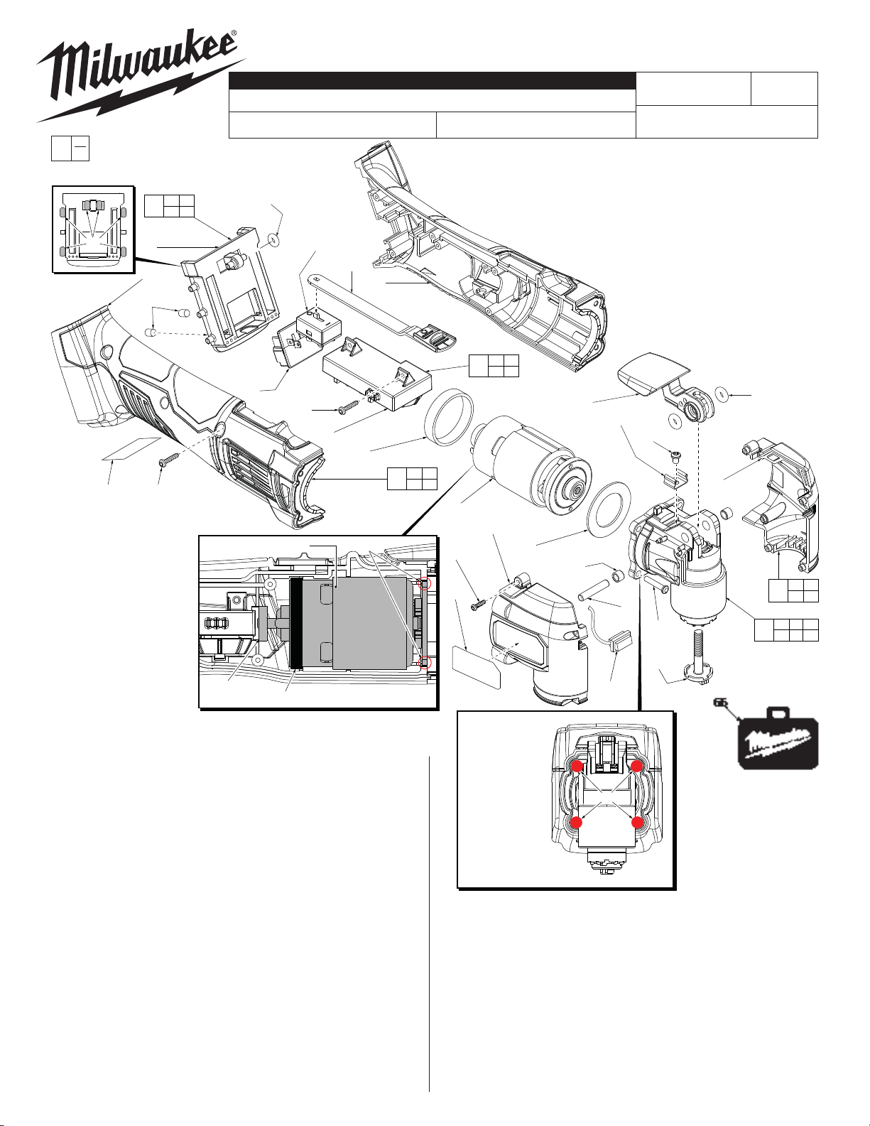
SERVICE PARTS LIST
SPECIFY CATALOG NO. AND SERIAL NO. WHEN ORDERING PARTS
M18™ MULTI-TOOL
CATALOG NO. 2626-20
STARTING
SERIAL NO.
F40A
BULLETIN NO.
54-22-2600
REVISED BULLETIN
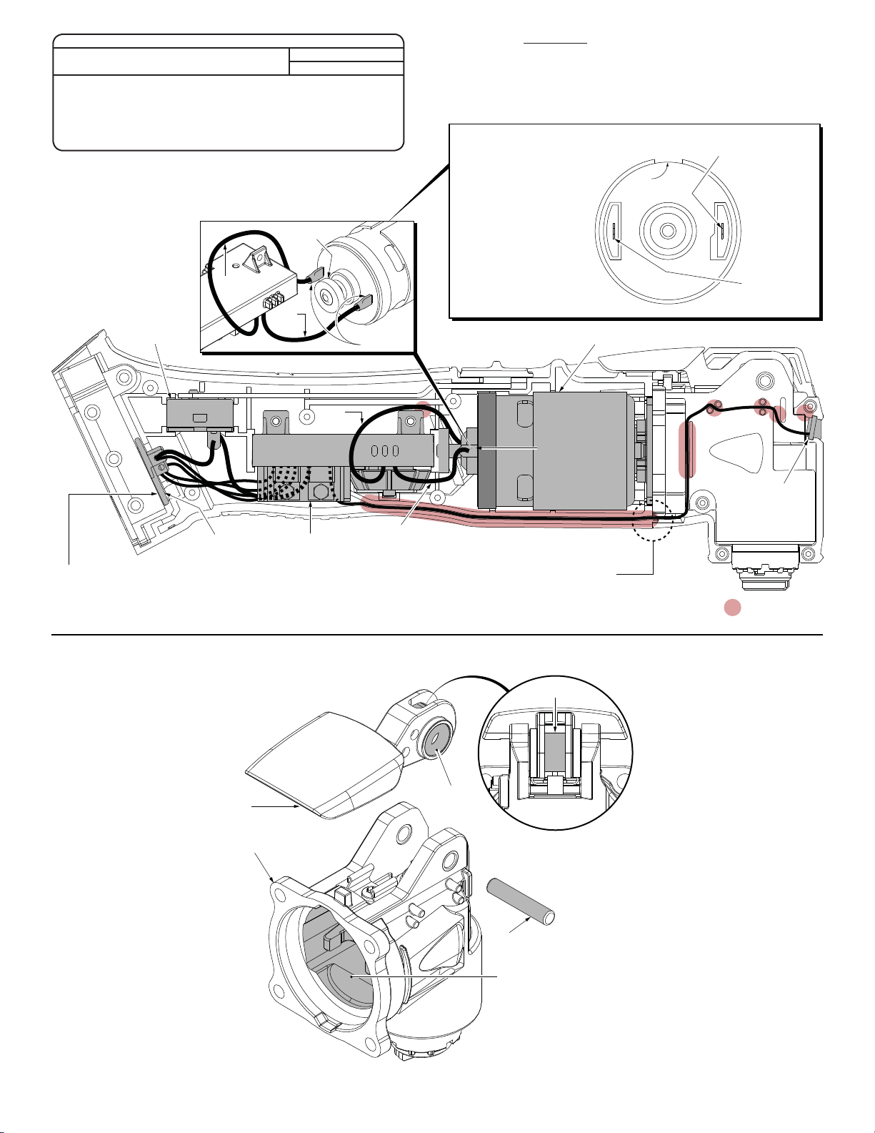
WIRING INSTRUCTION
See Page Two
DATE
Nov. 2013
12 13
62
14
13
17 16(5x)
When replacing Motor
Assembly #63, be sure to
reuse Motor Band #20.
Place the motor band flush
to the end of the motor
canister as shown. Be sure
not to cover motor vents.
IMPORTANT:
Do not attempt to make
adjustments to the magnet
ring or any other component on the motor assembly.
When reinstalling a motor
assembly, be sure to orient the ‘lobes’ of the motor mount at the 12:00 and
6:00 position prior to placing the motor assembly in Left Rear Handle #2.
FIG. PART NO. DESCRIPTION OF PART NO. REQ.
1 --------------- Front Housing - Left 1
2 --------------- Rear Handle - Left 1
3 44-10-0225 Quick Release Lever 1
4 05-88-0045 M4 x 0.7 x 8mm Pan Hd. Taptite Phillips Scr 1
5 42-70-0510 Clip 1
6 34-40-0077 Rubber O-Ring 2
7 42-40-0125 Nylon Bushing 2
9 45-24-1030 Switch Slide 1
10 --------------- On-Off Switch 1
11 --------------- Terminal Block 1
12 44-66-0392 Terminal Block Plate 1
13 43-86-0005 Rubber Isolators 6
14 45-30-1000 Silicone Slug 2
15 --------------- LED Assembly 1
16 06-82-1080 M3 x 14mm Pan Hd. Plastite T-10 Screw 7
17 10-20-2743 Warning Label 1
18 --------------- PCBA 1
20 42-16-0450 Motor Band (Rubber) 1
22 --------------- Rear Handle - Right 1
29 45-88-0088 Washer 1
31 44-60-0605 5.0 x 26mm Pin 1
32 --------------- Front Housing - Right 1
33 06-82-2385 M2.6 x 14mm Pan Hd. Plastite T-8 Screw 5
34 12-20-2638 Service Nameplate 1
12
22
14
13(6x)
10
9
11
16(2x)
18
20
Motor Assembly #63 Lobes
Magnet
Ring Motor Band #20
2
60
10 11
61
15 18
3
5
4
2 16
17 22
63
32
33
(5x)
34
Alternate the
tightening pattern
for gearcase
screws #42 as
shown.
Seat torque to
be 19.5 in/lbs
(21.5 kg/cm)
Order is 1,2,3,4
than 1,2,3,4 again
FIG. PART NO. DESCRIPTION OF PART NO. REQ.
42 05-88-0400 M4 x 20mm Fillister Hd. T-20 Screw 4
47 06-75-0025 Blade/Backing Pad Screw 1
60 31-44-1055 Rear Handle Assembly 1
61 14-20-2626 Switch/Electronics Assembly 1
62 14-67-0130 Terminal Block Plate Assembly 1
63 14-50-0705 Motor Assembly 1
64 14-38-2000 Front Housing Assembly 1
65 14-29-2626 Gearcase Assembly 1
66 48-55-3500 Carrying Case 1
29
7(2x)
31
42
(4x)
47
15
1
4
MILWAUKEE ELECTRIC TOOL CORPORATION
3
42
2
13135 W. Lisbon Road, Brookfi eld, WI 53005
1
6(2x)
64
65
1 32
33 34
3 4 5
6 7 31
Drwg. 3
SEAT TORQUE
FIG. PART NO. WHERE USED (KG/CM) (IN/LBS)
4 05-88-0045 Gearcase (Top) / Clip 13±2 11.5±1.5
16 06-82-1080 Rear Handle - Right 10±2 8.5±1.5
16 06-82-1080 PCBA 10±2 8.5±1.5
33 06-82-2385 Front Housing - Right 7±1 6±1
42 05-88-0400 Gearcase (Front) 21.5±2 18.5±1.5
NOTE:
Route the blue wire (from the PCBA to the negative motor terminal)
behind the PCBA screw lobe. Be sure to tuck the blue wire down
into the rear handle as much as possible, away from the magnet
ring of the motor assembly.
It is recommended to use
heat shrink tubing over the
soldered wires / motor
terminals as shown.
SCREW TORQUE SPECIFICATIONS
Magnet
Ring
Blue Wire
Red
On-Off
Switch
Wire
+
Heat Shrink
Tubing
Blue
Wire
It is recommended to hand tighten Rear Handle Screws #16, PCBA
Screws #16 and Front Housing Screws #33 to prevent over tightening.
Exercise caution when tightening screws if a cordless driver drill is used.
Proper orientation of the
Motor Assembly #63 is
with the slot in the motor
canister to the top at the
12:00 position.
This rear view of the motor
assembly is shown without
the rubber motor band #20
in place so the slot at the
top could be seen.
Motor Assembly
Positive Motor
Terminal
Positive motor terminal is surrounded
by a plastic ledging with a step
Slot
in it. Connect red
wire from PCBA
to this terminal.
+
terminal has
Connect blue
wire from PCBA
to this terminal.
The plastic
around the
negative
no step.
ledging
Terminal
Block
NOTE:
Terminal Block #11 must be
installed at the same time into
Terminal Block Plate #12.
LUBRICATION NOTES:
Use Type 'J' Grease,
No. 49-08-4220
When servicing, remove 90-95%
of the existing grease prior to installing Type “J”. Original grease
maybe similar in color but not
compatible with “J”.
PCBA
Place a light coating of grease on the
metal cam portion of the Quick Release
Lever #3 prior to installing on the
Gearcase Assembly #65.
3
65
Red Wire
Before securing the Right Rear Handle #22
and the Right Front Housing #32, be sure that
the LED wires are tucked completely down in
the wire trap. Be careful not to pinch the LED
wires in the area where the rear handles, front
housings and gearcase meet.
LED
= WIRE TRAPS
or GUIDES
Place a light coating of grease on the
O-Rings #6 (both sides) prior to installing
Metal Cam
6
Front View of #3
Quick Release Lever
Place a light coating of
grease on Metal Pin #31
prior to installing in the
Gearcase Assembly #65.
31
in the Quick Release Lever #3.
Fill the inside cavity of
Gearcase Assembly #65
with approximately .35oz.
(10g) of grease.
 Loading...