


20 21 22 23
SERVICE PARTS LIST
BULLETIN NO.
54-47-2565
124
40
31
42
40 31
42
SPECIFY CATALOG NO. AND SERIAL NO. WHEN ORDERING PARTS
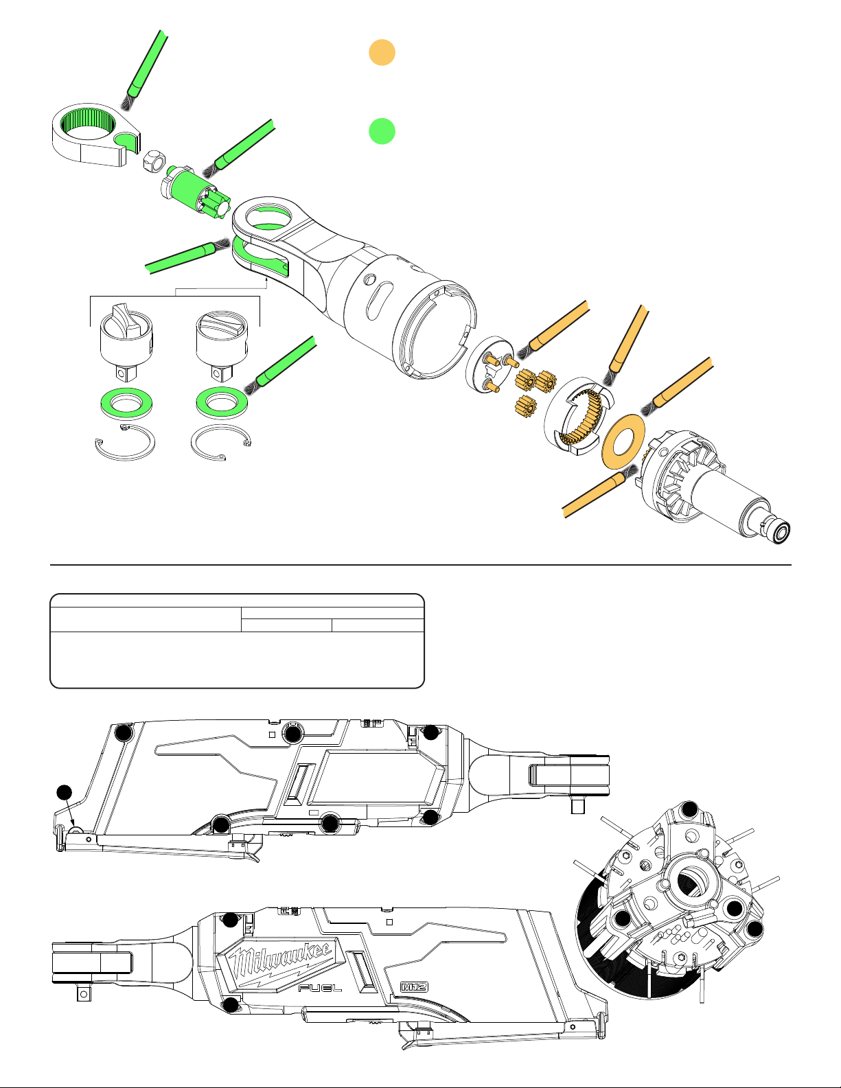
M12™ FUEL 3/8" HIGH SPEED RATCHET
2
CATALOG NO.
3
4
30
101
31
32
5
30 31
32
102
106
5
6
6
7 8
9 10
2567-20
7
8
(3x)
9
SERIAL
NUMBER
122
104
L83A
EXAMPLE:
00
Component Parts (Small #) Are Included
0
When Ordering The Assembly (Large #).
10
103
16
(4x)
19
13
15
104
22
REVISED BULLETIN
WIRING INSTRUCTION
See Pages 2 and 3
NOTE: Spring Pin (21)
and Switch Paddle (24)
must be removed in
order to access Screw
(18). See additional
23
DATE
Oct. 2020
18
21
24
note to the left.
17
18
(5x)
20
FIG. NOTES
17,19 Prior to installing a new nameplate or label,
23 apply isopropyl alcohol to handle cover with
a clean, lint free applicator and allowed to dry.
21 Use a thin blunt punch with the same OD or a
similiartoollikeanishingnailwithsameOD
and pointed tip ground down to remove spring
pin from the handle halves and switch paddle.
As an aid, be sure to prop up that corner
end of ratchet to support tapping out of the
spring pin. When reinstalling pin, align holes
and carefully press or tap the pin in place.
FIG. PART NO. DESCRIPTION OF PART NO. REQ.
2 45-98-0020 Yoke (1)
3 42-40-0017 Bushing (1)
4 36-17-0111 Crankshaft (1)
5 --------------- Yoke Housing with Needle Bearings (1)
6 44-60-0890 Drive Pin (1)
7 --------------- Carrier (1)
8 --------------- Planetary Gears (3)
9 --------------- Ring Gear (1)
10 --------------- Washer (1)
13 44-66-1006 Motor Plate (1)
14 05-84-0205 M2.5 x 31mm Skt. Hd. Hex Drive Screw (3)
15 006-82-2310 M3 x 8mm Pan Hd. Taptite T-10 Screw (1)
16 05-81-0594 M4 x 14mm Flat Hd. ST T-20 Screw (4)
17 12-20-2513 Service Nameplate (1)
18 05-71-0017 M4 x 10mm Pan Hd. ST T-20 Screw (5)
19 --------------- Right Housing Halve - Cover (1)
20 --------------- Left Housing Halve - Support (1)
21 44-60-0575 Spring Pin (1)
22 42-42-0119 Switch Lock-Out (1)
23 10-20-4419 Fuel Gauge Label (1)
24 44-10-0740 Switch Paddle (1)
30 --------------- 3/8" Anvil w/ Standard Shift Knob (1)
31 --------------- Friction Plate (1)
14
(3x)
24
FIG. PART NO. DESCRIPTION OF PART NO. REQ.
32 --------------- Retaining Ring (1)
40 --------------- 3/8" Anvil w/ Tall Shift Knob (Optional) (1)
42 --------------- Retaining Ring (1)
101 42-06-0138 3/8" Anvil Service Kit-Standard (1)
102 14-46-2560 Yoke Housing Service Kit (1)
103 16-01-2560 Rotor Service Assembly (1)
104 14-20-2560 Electronics Service Assembly (1)
105 31-44-2560 Housing Service Kit (1)
106 28-23-2500 Gear Set Service Kit (1)
121 42-55-2561 Contractor Bag (Optional, Accessory) (1)
122 49-16-2567 Rubber Boot (Optional, Accessory) (1)
124 49-06-2567 3/8" Anvil Service Kit-Tall (Optional, Accy.) (1)
MILWAUKEE TOOL l www.milwaukeetool.com
13135 W. LISBON RD., BROOKFIELD, WI 53005
105
104
16 17 18 19
21
121
Drwg. 1
LUBRICATION
Use DECH 5157 Grease, 49-08-0016 (26oz., 0.8kg plastic tub)
NOTE: When servicing, remove 90-95% of the existing grease prior to installing
DECH 5157 grease. Clean gear assemblies with a clean, dry cloth.
LUBRICATION
Use DECH 5166 Grease, 49-08-0018 (26oz., 0.8kg plastic tub)
NOTE: When servicing, remove 90-95% of the existing grease prior to installing
DECH 5166 grease. Clean gear assemblies with a clean, dry cloth.
NOTE
Regarding parts to be lubricated:
Apply a liberal amount of grease to all areas indicated. Be sure all teeth of gears
are pinion are completely coated.
Internal components of the anvil assemblies should come
from the factory pre-lubricated.
SEAT TORQUE
FIG. PART NO. WHERE USED (KG/CM) (IN/LBS)
14 05-84-0205 Motor Plate 5-7 4-6
15 06-82-2310 HV Terminal/Motor Plate 12-14 10-12
16 05-81-0594 Housing Cover 14-16 12-14
18 05-71-0017 Housing Cover/Support 10-12 8-10
SCREW TORQUE SPECIFICATIONS
18
18
18
18
18
16
16
16
14
14
15
14
16

Place electronics assembly into housing support.
Install LED lens as shown.
Place the HV wire
into wite trap.
Assemble on-off switch
into housing cavity.
1 2
Install yoke assembly onto
housing support/electronics assembly.
Assemble control board into housing slot.
3 4
Place battery
terminal block
into housing
cavity.
Push all wires down into housing
cavities as shown.
firmly and squarely
PRIOR TO INSTALLING THE HOUSING COVER
ONTO THE HOUSING SUPPORT, BE SURE THAT
THERE ARE NO INTERFERENCES.
5 6
components are
in place.
7
Install the switch lock-out slideBe sure that all
8
9
 Loading...