

EXAMPLE:
00
Component Parts (Small #)
0
Are Included When Ordering
The Assembly (Large #).
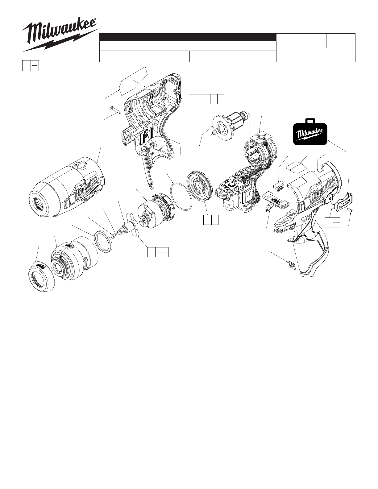
SERVICE PARTS LIST
SPECIFY CATALOG NO. AND SERIAL NO. WHEN ORDERING PARTS
M12™ FUEL™ 1/4" Impact Wrench with Friction Ring
CATALOG NO. 2552-20
39
STARTING
SERIAL NO.
30 31 32 34
47
35 39 40
J58A
BULLETIN NO.
54-26-2560
REVISED BULLETIN
WIRING INSTRUCTION
SEE PAGE 2
DATE
Apr. 2018
30
(7x)
52
18
44
6
4
5
3
2
1
4 5
50
6
31
46
49
18
45
33
35
32 40 34 51
36
36
48
37
37
FIG. PART NO. DESCRIPTION OF PART NO. REQ.
1 31-12-0053 Rubber Cap (1)
2 14-30-2502 Front Gear Case (1)
3 45-88-2135 Nylon Ring (1)
4 34-40-1880 O-Ring (1)
5 44-90-1070 1/4" Friction Ring (1)
6 --------------- 1/4" Square Anvil (1)
18 34-40-0303 O-Ring (1)
30 06-82-6351 M3 x 16mm Pan Hd. ST T-10 Screw (7)
31 --------------- Housing Cover - Right Housing (1)
32 23-28-0012 Light Pipe (1)
33 45-24-2553 Forward/Reverse Shuttle (1)
34 --------------- Housing Support - Left Housing (1)
35 42-70-0058 Housing Clip (1)
36 --------------- Belt Clip (1)
37 05-88-1015 M2.5 x 6mm Pan Hd. Phillips Mach. Sc (1)
39 12-20-2553 Service Nameplate (1)
40 10-20-2553 Spanish/French Warning Label (1)
44 14-30-2552 Impacting Assembly (1)
45 14-20-2552 Electronics Assembly (1)
46 16-01-2552 Rotor Assembly (1)
47 31-44-2553 Housing Kit (1)
48 42-70-0495 Belt Clip Kit (1)
49 44-66-0872 Gear Case End Cap Assy. with Bearing (1)
50 42-06-2552 Anvil Assembly (1)
51 42-55-0300 Zippered Canvas Tool Bag (1)
52 49-16-2553 Rubber Boot (Optional, Accessory) (1)
When servicing, remove 90-95% of the existing grease
prior to installing Type ‘J’. Original grease maybe similar
in color but not compatible with ‘J’.
FIG. LUBRICATION
(Type 'J' Grease, No. 49-08-4220):
2 Coat anvil opening in the front of the gear case with grease.
6 Lightly coat shaft surface of anvil (6) with grease.
44 Lightly coat the inside gear teeth of ring gear and the gear
teeth of the planet gears of impacting assembly (44) with
grease.
46 Coat pinion teeth of rotor assembly (46) with grease.
MILWAUKEE TOOL l www.milwaukeetool.com
13135 W. LISBON RD., BROOKFIELD, WI 53005
Drwg. 1
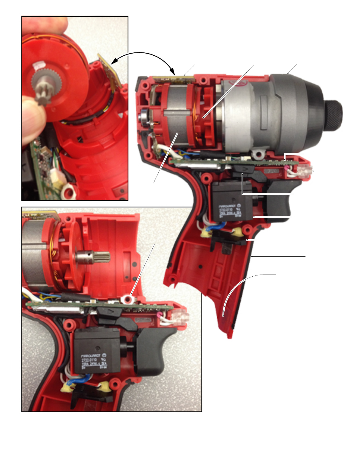
Prior to installing Stator/Rotor Assemblies, place the
Selector PCBA into the slotted Housing Support cavity.
Press wires into channel as shown. Carefully place
Stator/Rotor Assemblies into Housing Support, being
sure all components are firmly and squarely seated.
Stator
Ground
Terminal
Selector PCBA
Rotor
Gear Case Assembly
Model 2553-20
Shown
Main PCBA
LED
Assembly
Forward/Reverse
Shuttle
On-Off Switch
Battery Terminal Block
Connector
Housing Support
Housing Clip to be placed here
Prior to installing the Gear Case Assembly, be sure all
elements of the Electronics Assembly are seated properly
(Stator, Main PCBA, Selector PCBA, On-Off Switch, LED
Assembly and Battery Terminal Block Connector). Be sure the
Grounding Terminal is in place and that all wires are pressed
down into all wire traps and channels. Check to assure that
wires will not interfere with moving parts.
Prior to installing the Housing Cover, place Forward/Reverse
Shuttle onto On-Off Switch and through Housing Support
opening. Check to assure that wires will not be pinched.
Secure the Housing Cover to the Housing Support with seven
M3 x 16mm ST T-10 Screws. Be sure to replace the Housing
Clip at the bottom of the battery opening.
 Loading...