

Milwaukee 2416-20 User Manual
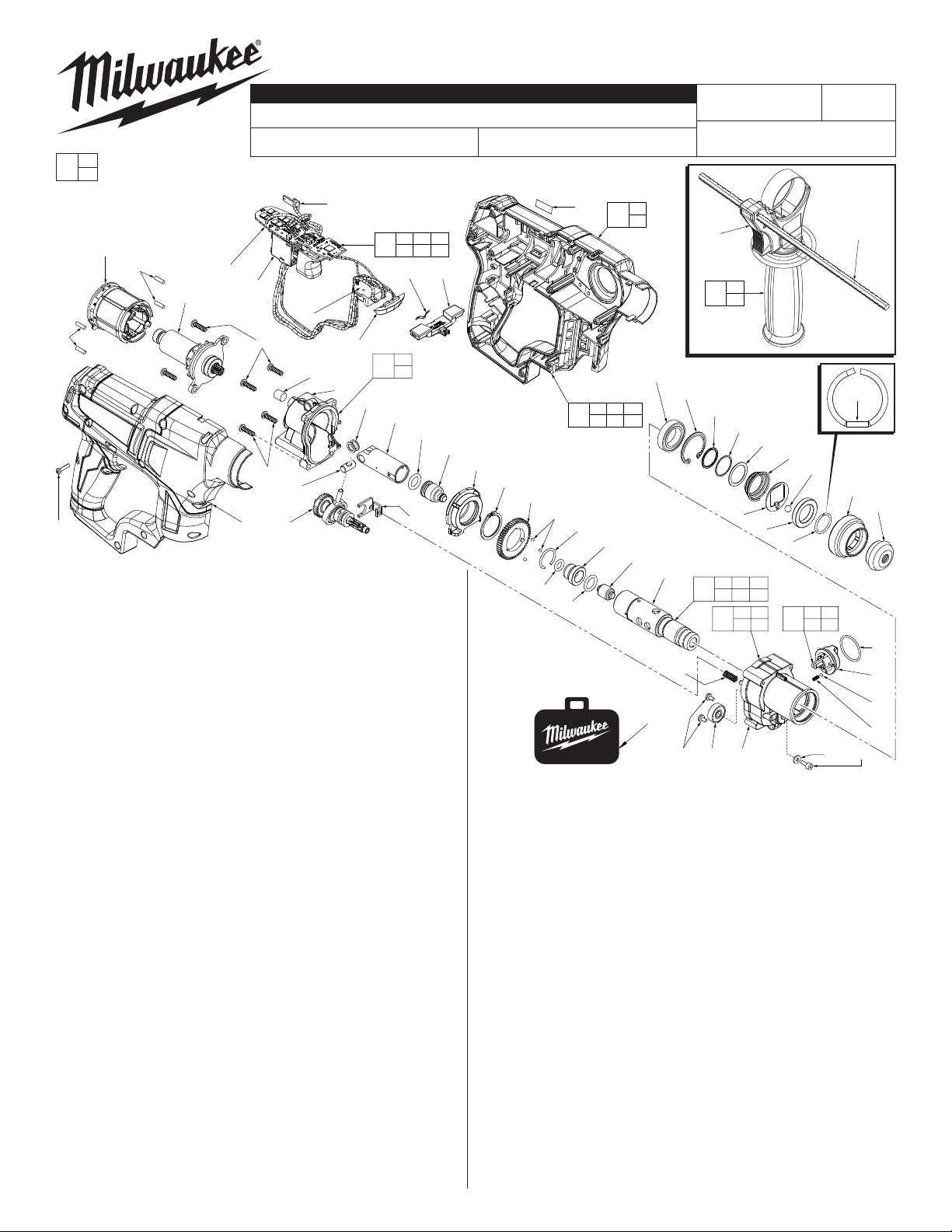
SERVICE PARTS LIST
SPECIFY CATALOG NO. AND SERIAL NO. WHEN ORDERING PARTS
M12 FUEL™ SDS Rotary Hammer
EXAMPLE:
00
Component Parts (Small #) Are Included
0
When Ordering The Assembly (Large #).
= Component of the 14-46-2416
Service Maintenance Kit.
See Page 2.
54
56
52
56
57
(14x)
FIG. PART NO. DESCRIPTION OF PART NO. REQ.
1 42-52-5262 Cap (1)
2 42-96-0035 Sleeve (1)
3 44-90-0106 Snap Ring (1)
4 44-90-0107 Holding Ring (1)
5 02-02-0146 6.5mm Steel (1)
6 42-36-0039 Support Plate (1)
7 40-50-5262 Pressure Spring (1)
8 45-88-0226 Flat Washer (1)
9 45-88-0227 Flat Washer (1)
10 44-90-0108 Spiral Retaining Ring (1)
11 34-80-0210 Retaining Ring (1)
12 02-04-0315 Ball Bearing (1)
13 05-84-0005 M3 x 0.5mm x 8.0mm Socket Screw (1)
14 45-88-0107 Flat Washer (1)
15 --------------- Gearcase with Shift Pin (1)
16 40-50-1220 Spring (1)
17 02-02-1230 3.0 Steel Ball (4)
18 44-10-0605 Shift Knob (1)
19 02-04-0325 Ball Bearing (1)
20 34-40-0533 O-Ring (1)
21 05-81-0020 M3.0 x 5 Pan Hd. ST Screw (2)
23 40-50-1215 Shifter Spring (1)
24 38-50-0420 Spindle (1)
25 45-08-0505 Anvil (1)
26 34-40-0530 O-Ring (1)
27 45-22-0008 Sleeve (1)
28 34-40-0531 O-Ring (1)
29 44-90-0109 Snap Ring (1)
30 32-44-1130 2nd Stage Gear (1)
31 34-60-0140 Retaining Ring (1)
32 28-72-0035 Bearing Holder Assy. with Needle Bearing (1)
34 45-56-0025 Striker (Ram) (1)
35 34-40-0532 O-Ring (1)
36 44-62-0147 Piston (1)
37 45-88-0228 Wrist Washer (2)
38 44-60-0555 Wrist Pin (1)
39 10-20-1341 Warning Label (Not Shown) (1)
40 --------------- Rear Gearcase (1)
41 43-84-0300 Felt Plug (1)
42 05-74-0010 M4 x 16mm Pan Hd. T-20 Screw (4)
43 05-74-0012 M4 x 20 Screw (2)
44 14-34-0650 Auxiliary Side Handle (Optional) (1)
45 44-94-5381 Depth Rod (Optional) (1)
46 44-66-0405 Shifting Clip (1)
47 36-92-0300 Wobble Shaft Assembly (1)
52 14-50-0050 Rotor Assembly (1)
54 --------------- Stator (1)
56 45-30-0270 Rubber Slugs (4)
57 06-82-2385 M3 x 14mm Pan Hd. Plastite T-10 Screw (14)
CATALOG NO. 2416-20
67
66
65
64
42(4x)
41
40
43
38
58 47
NOTE: Fuel Gauge #67 is hot melted
into Support Housing #59. Fuel gauge
is than plugged into
PCBA #66.
54 64 65
70
66 69
62
61
69
40
75
41
37
36
35
34
46
BULLETIN NO.
54-24-2430
REVISED BULLETIN
STARTING
SERIAL NO.
32
31
30
17
28
See page 2
for fastener
torque chart
FIG. PART NO. DESCRIPTION OF PART NO. REQ.
58 --------------- Cover Housing (1)
59 --------------- Support Housing with Fuel Gauge (1)
60 10-20-0304 Fuel Gauge Label (1)
61 42-42-0185 Forward / Reverse Shuttle (1)
62 40-50-1135 Shuttle Spring (1)
63 12-20-2416 Service Nameplate (Not Shown) (1)
64 --------------- Contact Plate Holder (1)
65 --------------- Switch (1)
66 --------------- PCB Assembly (1)
67 --------------- Fuel Gauge (1)
68 42-55-2416 Carrying Case (1)
69 --------------- LED Lens (1)
70 23-66-2416 Switch / Electronics Assembly (1)
71 44-10-0610 Shift Knob Assembly (1)
72 14-34-0620 Handle Housing Assy. with Fuel Gauge (1)
73 14-46-1450 Side Handle Assembly (Optional) (1)
74 38-50-0425 Spindle Assembly (1)
75 14-30-0070 Rear Gearcase Assy. with Needle Bearing (1)
76 14-30-0066 Front Gearcase Assembly (1)
FIG. NOTE:
3,24 There is a 'fl at' that is opposite the opening on the snap ring.
Align 'fl at' on snap ring with 'fl at' on spindle.
5,6 Position ball notch on support plate and ball towards 'fl ats'.
13 Apply a drop of Blue Loctite® 242 or the equivelant to the
threads of screw prior to installing in front gearcase.
26
60
72
29
F01A
59
67
12
56 57 58
59 60 67
27
25
MILWAUKEE ELECTRIC TOOL CORPORATION
11
24
23
68
21 19 15 14 13
13135 W. Lisbon Road, Brookfi eld, WI 53005
WIRING INSTRUCTION
SEE PAGE 4
44 45
44
73
45
10
9
8
7
6
4
3
24 25 26
74
27 28 29
15 19
76
21
71
DATE
Nov. 2012
Side Handle
Assembly
14-46-1450
(Optional)
Flat
5
2
16 17
18 20
1
20
18
17
16
Drwg. 1
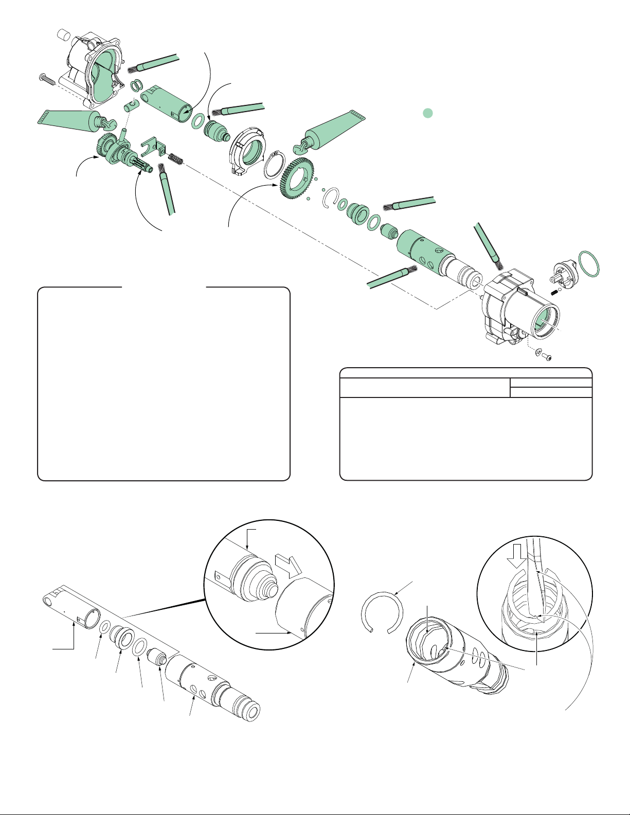
Place approximately
13 grams (.5 oz.) of
grease over the wobble
bearing and 1st gear of
the wobble shaft
assembly #47.
Apply a thin film of grease
to the inside of piston #36.
No grease on the back
flat of ram #34.
LUBRICATION NOTES:
Type ‘S2’ Grease
No. 49-08-5262, 1.4oz. / 40g tube
Prior to reinstalling, clean gear assemblies
with a clean, dry cloth. Lightly coat all parts
highlighted here with ‘S2’ grease. Apply a
greater amount of grease to all internal and
external gear teeth.
Place a total of 13 grams
(.5 oz.) of grease over the
pinion gearing of wobble shaft
assembly #47 and the 2nd
stage gear #30.
ROTARY HAMMER SERVICE MAINTENANCE KIT
FIG. PART NO. DESCRIPTION OF PART NO. REQ.
1 42-52-5262 Cap 1
2 42-96-0035 Sleeve 1
3 44-90-0106 Snap Ring 1
5 02-02-0146 6.5mm Steel Ball 1
13 05-84-0005 M3 x 0.5 x 8.5 mm 1
14 45-88-0107 Flat Washer 1
16 40-50-1220 Spring 1
17 02-02-1230 3.0 Steel Ball 1
20 34-40-0533 O-Ring 1
26 34-40-0530 O-Ring 1
28 34-40-0531 O-Ring 1
29 44-90-0109 Snap Ring 1
35 34-40-0532 O-Ring 1
37 45-88-0228 Wrist Pin Washer 2
41 43-84-0300 Felt Plug 1
- 49-08-5262 1.4 oz. / 40gr. Tube 'S 2' Grease 1
14-46-2416
NOTE:
As an aid to installing items #25, #26, #27 and #28 squarely into spindle
#24, the following steps should be followed:
1. Place o-ring #28 inside sleeve #27.
2. Place anvil #25 inside sleeve #27.
3. Slide o-ring #26 onto anvil #25.
Piston
#36
4. Place that assembly of parts on top of
an old piston #36 and gentily insert
into the back end of spindle #24 until
parts bottom out. Remove piston.
SEAT TORQUE
FIG. PART NO. WHERE USED (KG/CM) (IN/LBS)
13 05-81-0005 Gearcase (Bottom) 15-19 13-16
21 05-81-0020 Ball Bearing Retainers 8-12 7-10
42 05-74-0010 Rear Gearcase (Top) 12-17 10-14
42 05-74-0010 Motor Mounting Plate 12-17 10-14
43 05-74-0012 Rear Gearcase (Bottom) 12-17 10-14
57 06-82-2385 Cover Housing 8-10 7-8
NOTE:
As an aid to installing snap ring #29 into spindle #24, rest the snap
ring on rear spindle, perpendicular to the opening. To condense the
snap ring, use a flat blade screwdriver to push snap ring down into the
spindle cavity. Push the snap ring past the shoulder in the spindle
before rotating the snap ring in the cavity.
Press snap ring into the retaining slot,
securing items 25, 26, 27 and 28.
SCREW TORQUE SPECIFICATIONS
Snap Ring
#29
Shoulder
Piston
#36
O-Ring #28
Sleeve #27
O-Ring #26
Anvil #25
Spindle #24
Spindle
#24
Retaining
slot in spindle
Spindle #24
NOTE:
As an aid to installing snap ring, it may be helpful to file or grind a
notch in the bottom flat of the screwdriver to accommodate the round
of the snap ring. As force is applied to the snap ring, the open end of
the ring will close in on the screwdriver. It may be necessary to do
additional modifications to the screwdriver (grinding the sides of the
blade or shaft) to allow for the insertion of the ring and the removal of
the screwdriver.
#24
 Loading...