

Milwaukee 1500HT User Manual
P
EPA CERTIFIED
WOOD BURNING
STOVE
INSTALLATION AND OPERATION
MANUAL
RETAIN THESE
INSTRUCTIONS
FOR FUTURE
MODEL 1500HT
REFERENCE
THIS APPLIANCE MUST BE INSTALLED BY A QUALIFIED INSTALLER. READ
ENTIRE MANUAL THOROUGHLY BEFORE INSTALLATION.
P/N 775001M, Rev. Q, 12/03

IMPORTANT WARNINGS
CAUTION: PLEASE READ THIS ENTIRE MANUAL BEFORE YOU INSTALL AND USE YOUR NEW ROOM
HEATER. FOR YOUR SAFETY, FOLLOW THE INSTALLATION, OPERATION AND MAINTENANCE INSTRUCTIONS EXACTLY, WITHOUT DEVIATION. FAILURE TO FOLLOW THESE INSTRUCTIONS MAY RESULT IN
PROPERTY DAMAGE, BODILY INJURY, OR EVEN DEATH. IF THIS APPLIANCE IS NOT PROPERLY INSTALLED,
A HOUSE FIRE MAY RESULT. CONTACT YOUR LOCAL BUILDING OR FIRE OFFICIALS ABOUT RESTRICTIONS
AND INSTALLATION INSPECTION REQUIREMENTS IN YOUR AREA.
1. If utilizing an older chimney, it must be in-
spected for adequate serviceability. Refer to the
heading Chimney Inspection on page 9 of this
manual.
2. The minimum clearances must be maintained
for all combustible surfaces and materials in-
cluding; furniture, carpet, drapes, clothing,
wood, papers, etc. Do not store firewood within
this clearance space. Failure to maintain clear-
ances to all combustibles may result in a house
fire.
3. This appliance requires non-combustible floor
protection as outlined in this manual (see Floor
Protection on page 6 for additional information).
4. Minimum ceiling height must be 7 feet (213 cm)
(measured from base of appliance to ceiling).
5. DO NOT CONNECT THIS UNIT TO A CHIMNEY
FLUE CONNECTED TO ANOTHER APPLIANCE.
6. Do not connect this appliance to air ducts or
any air distribution system.
7. PREVENT CREOSOTE FIRE: Inspect and clean
chimney frequently. Under certain conditions of
use, creosote buildup may occur rapidly. In-
spect chimney connector and chimney twice
monthly and clean if necessary. Using green or
inadequately seasoned wood can greatly in-
crease creosote buildup. Use dry wood to mini-
mize creosote buildup.
8. USE SOLID WOOD FUEL ONLY: This appliance
is approved for burning dry seasoned natural
wood only. CAUTION: BURN UNTREATED
WOOD ONLY. DO NOT BURN GARBAGE OR
FLAMMABLE FLUIDS SUCH AS GASOLINE,
NAPHTHA OR ENGINE OIL.
9. Never use gasoline, gasoline-type lantern fuel,
kerosene, charcoal lighter fluid, or similar liq-
uids to start or "freshen up" a fire in this heater.
Keep all such liquids well away from the heater
while it is in use.
10. DO NOT OVERFIRE: If heater or chimney connector glows, you are overfiring. Overfiring this
appliance could cause a house fire. Overfiring is
a condition where the appliance is operated at
temperatures above its design capabilities.
Overfiring can be caused by improper installation, improper operation, lack of maintenance or
improper fuel usage. Damage caused from overfiring is NOT covered under the manufacturers
limited warranty.
11. NEVER LEAVE AN UNATTENDED STOVE
BURNING ON HIGH. Operation of the stove with
the primary air control at its highest burn rate
setting for extended periods can cause dangerous overfiring conditions. The primary air control should only be positioned at the highest
setting during start-up procedures and for short
durations. When leaving the stove unattended
ensure that the primary air control is set to the
low or medium low range.
12. Use a metal container with a tight fitting lid to
dispose of ashes.
13. IN THE EVENT OF A COMPONENT FAILURE,
USE ONLY COMPONENTS PROVIDED BY THE
MANUFACTURER AS REPLACEMENT PARTS.
14. Burning any kind of fuel uses oxygen from the
dwelling. Be sure that you allow an adequate
source of fresh air into the room where the
stove is operating (see Ventilation and Outside
Air on page 6).
15. CAUTION: HOT WHILE IN OPERATION. An appliance hot enough to warm your home can severely burn anyone touching it. Keep children,
clothing and furniture away. Contact may cause
skin burns. Do not let children touch the appliance. Train them to stay a safe distance from
the unit.
16. Do not operate this appliance without the firebox baffle brick properly installed.
17. Build fires directly upon the brick hearth inside
the stove. Do not use grates, irons or any other
method to elevate the fire.
18. SAVE THESE INSTRUCTIONS.
19. See the listing label located on the back of
stove (or see Safety/Listing Label on page 24).
PAGE 2

TABLE OF CONTENTS
Important Warnings ................................................ 2
Testing/Listing, EPA, Using this Manual.................. 3
Planning Your Installation ..................................... 4-6
Manufactured (Mobile) Home Requirements ...........6
Installation .......................................................... 7-12
Product Features and Controls ..............................13
Care and Operation .......................................... 13-14
Recommended Fuel ...............................................15
Maintenance ..................................................... 15-17
Troubleshooting ................................................ 18-19
Specifications..........................................................20
Replacement Parts List..................................... 21-22
Optional Accessories ..............................................23
Safety/Listing Label.................................................24
EPA Label ...............................................................25
Ownership Records ...............................................26
TESTING/LISTING
Model 1500HT has been tested to UL Standards 1482
and ULC-S627 OMNI Test Laboratories Inc, Beaverton,
Oregon, Report #030-S-03-2.
EPA CERTIFICATION
This heater has been tested to rigorous emissions standard, and has been certified by the Environmental Protection Agency.
CONGRATULATIONS ON THE PURCHASE OF
YOUR NEW WOODSTOVE MANUFACTURED BY
LENNOX HEARTH PRODUCTS.
When you purchased your new woodstove, you
joined the ranks of thousands of concerned individuals whose answer to their home heating needs
reflects their concern for aesthetics, efficiency and
our environment. We extend our continued support
to help you achieve the maximum benefit and enjoyment available from your new wood stove.
It is our goal at Lennox Hearth Products to provide
you, our valued customer, with an appliance that
will ensure you years of trouble-free warmth and
pleasure.
Thank you for selecting a Lennox Hearth Products
stove as the answer to your home heating needs.
Sincerely,
All of us at Lennox Hearth Products
PACKAGING LIST
This appliance is packaged with an accessory package,
which contains the following:
One - Installation and operation instructions manual
One - Warranty
Five - Baffle bricks
One - Marble set (for stove top and ash lip)
One - Insulation pad and strips. Place pad under top
marble and strips under ash lip marble.
USING THIS MANUAL
Please read and carefully follow all of the instructions
found in this manual. Please pay special attention to the
safety instructions provided in this manual. The Homeowner’s Care and Operation Instructions included here
will assure you have many years of dependable and
enjoyable service from your appliance.
PAGE 3

PLANNING YOUR INSTALLATION
QUESTIONS TO ASK LOCAL BUILDING OFFICIAL
A correct installation is critical and imperative for reducing fire hazards and perilous conditions that can arise
when wood burning appliances are improperly installed.
The installer must follow all of the manufacturers’ instructions.
The installation of a wood burning appliance must conform to local codes and applicable state and federal
requirements. Familiarity with these requirements before installation is essential. Important considerations to
discuss with local building officials include:
1. Applicable codes (i.e. Uniform Mechanical Code,
State or Regional Codes)?
Electrical codes: Optional Blower Assemblies have
a flexible electrical cord that must be electrically
grounded per local codes or per electrical codes:
In USA, NEC, ANSI/NFPA 70-1987
In Canada, CSA C22.1
WARNING: ELECTRICAL GROUNDING
INSTRUCTIONS: THIS APPLIANCE IS
EQUIPPED WITH A THREE-PRONG
(GROUNDING) PLUG FOR YOUR PROTECTION AGAINST SHOCK HAZARD
AND SHOULD BE PLUGGED DIRECTLY
INTO A PROPERLY GROUNDED THREEPRONG RECEPTACLE. DO NOT CUT OR
REMOVE THE GROUNDING PRONG
FROM THIS PLUG.
2. Local amendments?
3. Is a permit required - cost?
(You may wish to contact your insurance company
to ask if they require this).
4. Is outside combustion air required?
5. Rooms where the installation is not allowed?
SMOKE DETECTORS
Since there are always several potential sources of fire
in any home, we recommend installing smoke detectors. If possible, install the smoke detector in a hallway
adjacent to the room (to reduce the possibility of occasional false activation from the heat produced by the
stove). If your local code requires a smoke detector be
installed within the same room, you must follow the requirements of your local code. Check with your local
building department for requirements in your area.
NOTE – This appliance is NOT
tion into a Manufactured (Mobile) Home in Canada.
approved for installa-
SELECTING A LOCATION
The design of your home and where you place your
stove will determine its value as a source of heat. A
wood stove depends primarily on air circulation (convection) to disperse its heat, and therefore, a central
location is often best. There are other practical considerations, which must be considered before a final selection of locations is made.
♦ Existing Chimneys
♦ Wood Storage
♦ Aesthetic Considerations
♦ Roof Design (Rafter Locations & Roof Pitch)
♦ Room Traffic
♦ Proximity to Combustibles
♦ Electrical Wiring
The installation of this stove will require some research.
Once your options are determined, consult with your
local building department who will be able to give you
the necessary installation requirements for your area (Is
a building permit required, Rooms where installation
may not be allowed, etc.).
WARNING: CHECK ALL LOCAL BUILDING AND
SAFETY CODES BEFORE INSTALLATION. THE INSTALLATION INSTRUCTIONS AND APPROPRIATE
CODE REQUIREMENTS MUST BE FOLLOWED EXACTLY AND WITHOUT COMPROMISE. ALTERATIONS TO THE STOVE ARE NOT ALLOWED. DO
NOT CONNECT THE STOVE TO A CHIMNEY SYSTEM SERVING ANOTHER STOVE, APPLIANCE, OR
ANY AIR DISTRIBUTION DUCT. FAILURE TO FOLLOW THESE INSTRUCTIONS WILL VOID THE
MANUFACTURERS WARRANTY.
If you plan to vent your stove into an existing masonry
chimney, have it inspected by a local fire marshal or
qualified installer. Remember that a stove's performance is heavily influenced by the chimney and its location on the roof. An oversized flue may not provide effective draw, and a flue liner may be required (see Draft
Requirements, page 10). Consult your dealer or qualified installer before final selection is made.
This stove requires pre-installation work to be completed before installation can take place. This will include the preparation of the floor and appropriate
hearth pad for acceptance of outside air (if applicable),
and for modification for flue and chimney.
PAGE 4
PLANNING YOUR INSTALLATION
COMBUSTIBLE WALL CLEARANCE
WARNING: IT IS VERY IMPORTANT THAT YOU
OBSERVE THE MINIMUM CLEARANCES.
There are listed clearances for your stove which were
determined in a Laboratory test using various "classes"
of stove pipe or chimney. Minimums are first established for the stove itself and increased based on how
much heat is transferred by each class of pipe.
Note: Manufactured (mobile) home installations require
the use of a Type L Vent Chimney connector only. Use
of a single wall flue pipe connection is not permitted.
Residential Reduced Clearance
Using Listed L Vent pipe (double wall air insulated) to
the top of the stove.
Approved brands are: Jakes-Evans, Dura-Vent, Security, Pro-Vent, Ameri-Tek, Metal Bestos.
Clearances (inches / millimeters)
A. 10 ½ / 267 C. 15 / 381 E. 9 ½ / 241
B. 20 / 508 D. 8 / 203 F. 5 / 127
Residential Standard (not approved for manufactured [mobile] homes)
Using single wall pipe connector to the top of the stove.
Clearances (inches / millimeters)
A. 15 / 381 C. 15 / 381 E. 8 ½ / 216
B. 19 / 483 D. 13 / 330 F. 5 / 127
Manufactured (Mobile) Home Standard Clearance
Using Approved L Vent only. Approved brands are
Dura-Vent, Security, Pro-Vent, and Ameri-Tek. Manufactured (mobile) Home installations must use a rain
cap with a spark arrestor.
Clearances (inches / millimeters)
A. 10 ½ / 267 C. 15 / 381 E. 9 ½ / 241
B. 20 / 508 D. 8 / 203 F. 5 / 127
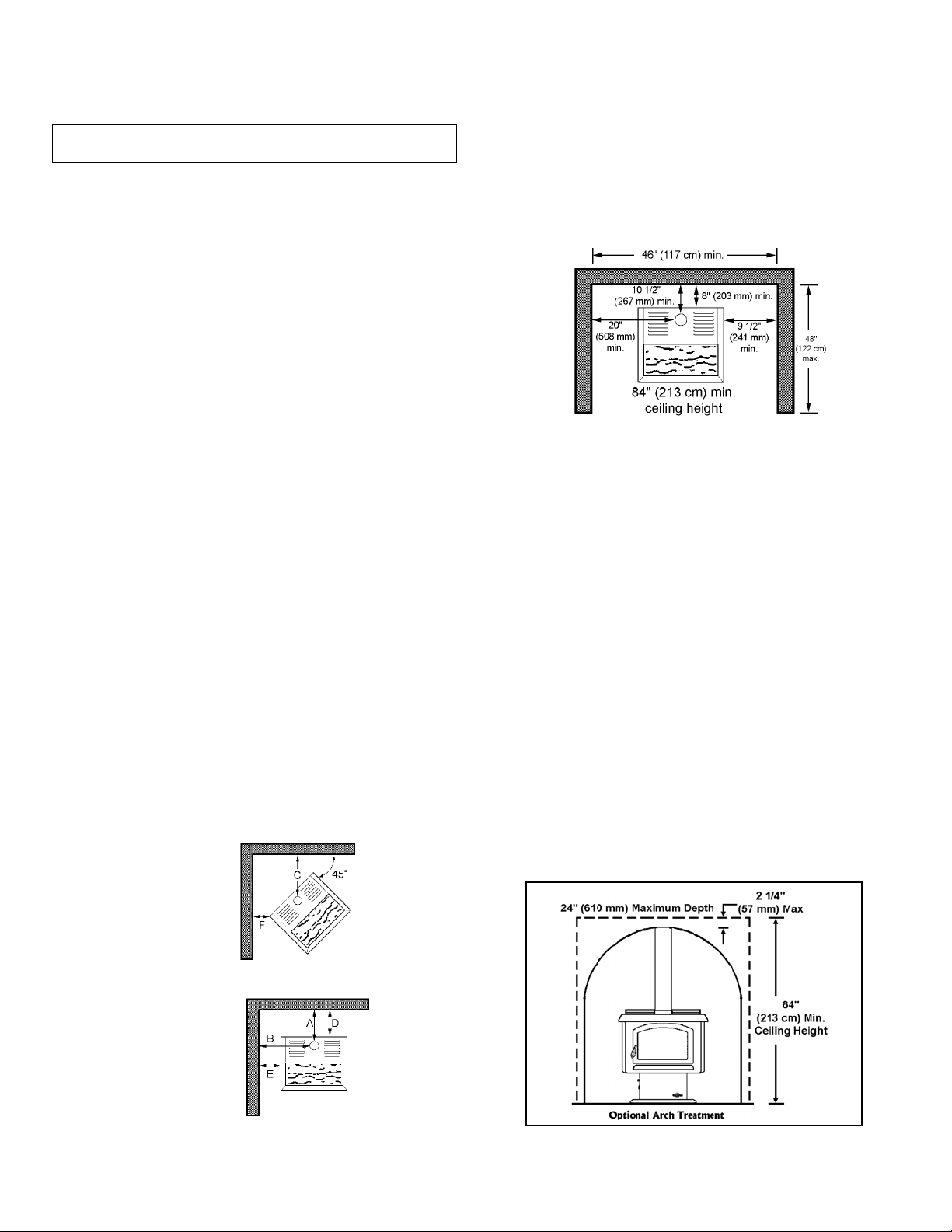
CORNER
INSTALLATION
PARALLEL
INSTALLATION
*ALCOVE CLEARANCE
Required pipe: Type L-Vent pipe to top of stove. Approved brands are Dura-Vent, Pro-Vent, Ameri-I-Tek,
Standex, and Metal Bestos.
Alcoves must have minimum dimensions of 84" (213
cm) height minimum, 46" (117 cm) width minimum and
24" (610 mm) depth maximum.
Alcove Clearances:
Back wall to pipe O.D. 10 1/2" (267 mm) Minimum
Side wall to pipe O.D. 20" (508 mm) Minimum
Back wall to stove 8" (203 mm) Minimum
Side wall to stove 9 1/2" (241 mm) Minimum
* NOTE:
PROTECTED WALL CLEARANCE
stalled adjacent to a protected wall system. The variance must
be approved by your local building official. Normally, the protected wall system is defined as a non- combustible material
with a minimum of 1" air space behind. Check your local building codes or with a qualified installer (Ref. NFPA 211).
OPTIONAL ARCH TREATMENT
An alcove depth of 24" (610 mm) (or less) will allow for a
minimum height of 84" (213 cm) and may be trimmed with a 2
1/4" (57 mm) maximum arch treatment if desired.
Alcove dimensions cannot be reduced by the use of
non-combustible materials such as brick, stone, etc. Alcove
dimensions listed are minimum dimensions and are not
measurements for building an Alcove. You will need to consider these clearances, as well as other dimensional requirements before you build the alcove and install this appliance.
when the stove is in-
PAGE 5
PLANNING YOUR INSTALLATION
REDUCED MASONRY STRUCTURE CLEARANCE
(ALCOVE)
Your Earth Stove can be installed in a masonry structure with reduced clearances if the structure was built to
National Building Code for fireplaces and chimneys
(UBC 37).
The firebox of the masonry structure must be of adequate size to allow a minimum of 6" (152 mm) clearance to the sides and top of the stove and 2" (51 mm)
clearance to the rear. All stove models must be installed
on their original listed legs or base unless otherwise
specified by OMNI Testing Laboratory.
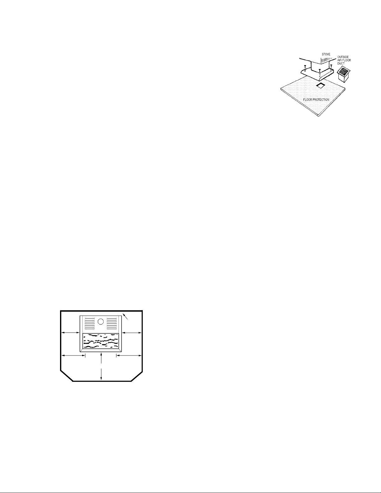
FLOOR PROTECTION
This appliance requires a non-combustible floor protection for ember protection. If the floor protection is to be
stone, tile, brick, etc., it must be mortared or grouted to
form a continuous non-combustible surface. If a chimney connector extends horizontally over the floor, protection must cover the floor under the connector and at
least 2" (51 mm) to either side.
The floor protection must extend completely beneath the
stove and to the front, sides, and rear as indicated:
USA REQUIREMENTS
16” minimum to the front of the fuel door glass
8" minimum beyond the sides of the fuel door opening
0” minimum to the back of the stove body
CANADA REQUIREMENTS
18” (457 mm) min. to the front of the fuel door glass
8” (203 mm) min. beyond the sides of the stove body
8” (203 mm) min. to the back of the stove body
STANDARD PARALLEL HEARTH PAD SHOWN
0” - USA
8” (203 mm)
Canada
8” (203 mm)
USA
18” (457 mm) –Canada
16” (406 mm) - USA
REMOVE ASH DRAWER CLIP
The ash drawer is secured for shipping with a small
retaining screw at the top of drawer. Remove and discard this screw.
VENTILATION
(Residential homes which do not require an outside
air inlet). Ventilation is essential when using a solid fuel
stove. The combustion process uses oxygen from inside the home and it may be necessary to open a window or install a vent to provide combustion air in a
house that is well insulated.
8” – Can.
8” (203 mm)
Canada
8” (203 mm)
USA
OUTSIDE AIR
In all manufactured (mobile) homes and in many
site built residences (subject to local code), a stove
may be required to use
outside air for combustion.
A 5 ¼” (133 mm) square
outside air floor duct is
available through your
dealer.
This stove can take in outside air directly through the base.
This type installation requires a hole through the floor protector and the use of outside air floor duct (catalog #
14M67) to penetrate into the air space below the home.
NOTE: Because the base sits 1" (25.4 mm) off the
floor, the outside air floor duct can be positioned along
the front to rear center line under the pedestal, but as
close to the opening in the base as location permits.
The outside air floor duct opening must be protected
from any possible obstruction including loose floor insulation.
MANUFACTURED (MOBILE) HOME REQUIREMENTS
This stove is certified as a Room Heater, Solid Fuel Type
and may be used in Manufactured Housing providing the
following requirements are followed:
• An outside air inlet must be provided for combustion and
be unrestricted while unit is in use.
• WARNING: DO NOT INSTALL IN SLEEPING ROOM.
• Regulations require that the appliance must be secured
to the floor and grounded to the chassis. See Securing
the Stove to the Floor (and) Grounding Stove, page 7.
• Required venting is 6” (152 mm) diameter Type L-Vent
connector pipe with listed factory-built 103HT chimney
suitable for use with solid fuels or a code approved masonry chimney. Approved brands of factory built chimney
are listed in this manual. Rain cap and spark arrestors are
required (see Clearances, page 5).
• CAUTION: THE STRUCTURAL INTEGRITY OF THE
MOBILE HOME FLOOR, WALL, AND CEILING/ROOF
MUST BE MAINTAINED.
• The chimney must provide for a section joint so that any
parts extending above 13' 6" (412 cm) from ground level
can be removed for transportation of the manufactured
(mobile) dwelling.
PAGE 6
INSTALLATION
SECURING THE STOVE TO THE FLOOR
Manufactured (Mobile) Homes Only
Once the outside air floor duct is in position, replace the
floor protector. Make sure that the floor protector's hole
is aligned with the outside air opening. Next position
and align the stove on the hearth pad. Manufactured
(mobile) home installations require that the stove be
secured to the floor. This ensures that the stove will not
shift when the manufactured (mobile) home is moved.
To do this, mark where the holes are to be drilled using
a marking instrument long enough and small enough to
fit through the (4) four holes in the stove base. Mark
holes, then remove the stove. Drill the (4) four holes,
with a 1/4" (7 mm) drill bit. Drill down through the floor
protector and the manufactured (mobile) home floor.
Use 1/4" (7 mm) lag bolts and secure to the manufactured (mobile) home floor.
NOTE: If the composition of the manufactured (mobile)
home floor is of light particleboard construction, you will
be required to secure the stove with regular hex head
bolts and nuts. This will ensure that the bolts will not rip
out of the floor when the manufactured (mobile) home is
being moved.
GROUNDING STOVE
Manufactured (Mobile) Homes Only
Regulations require that all stoves installed in manufactured (mobile) homes must be grounded. To do this
simply attach a piece of No. 8 copper wire, at least 18"
(457 mm) in length from the stove to the chassis of the
manufactured (mobile) home.
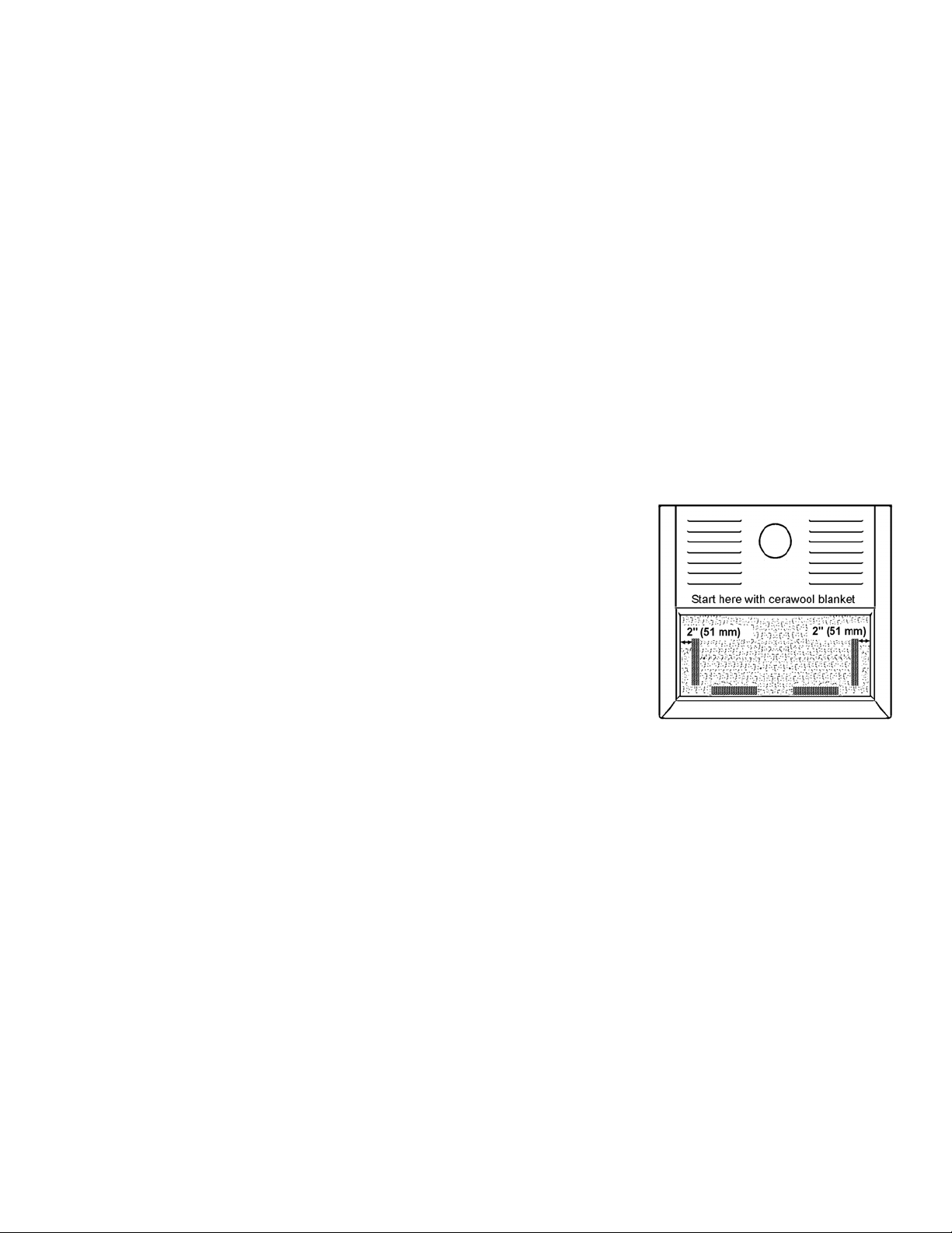
INSTALLING MARBLE ACCENTS
Marble is a natural product and therefore each piece
will have its own unique character. Marble can be
scratched so care should be taken to avoid putting
heavy or rough objects (trivet/steamers) on the surface.
If the marble should become scratched, the scratch
may be removed or diminished by polishing it with jewelers rouge (which can be purchased at many hardware
stores). Do not install the marble before curing the
paint.
The marble set consists of 2 pieces. A large piece
which fits onto the stove top and a smaller piece which
fits onto the ashlip which is located below the fuel door.
Install the marble gasket and marble as follows:
1. Install gasket on stove top as shown in the illustra-
tion. The ceramic fiber blanket and strips (cerawool)
which come
with each unit
must be placed
under the marble to insulate it
from the high
temperatures
on top of the
firebox. Do not
place the marble directly on
the top metal surface of the stove or it will crack.
2. Place top marble piece onto the gasket on stove
top
3. Place ashlip marble into recessed area on the stove
ashlip (located below the fuel door).
PAGE 7
INSTALLATION
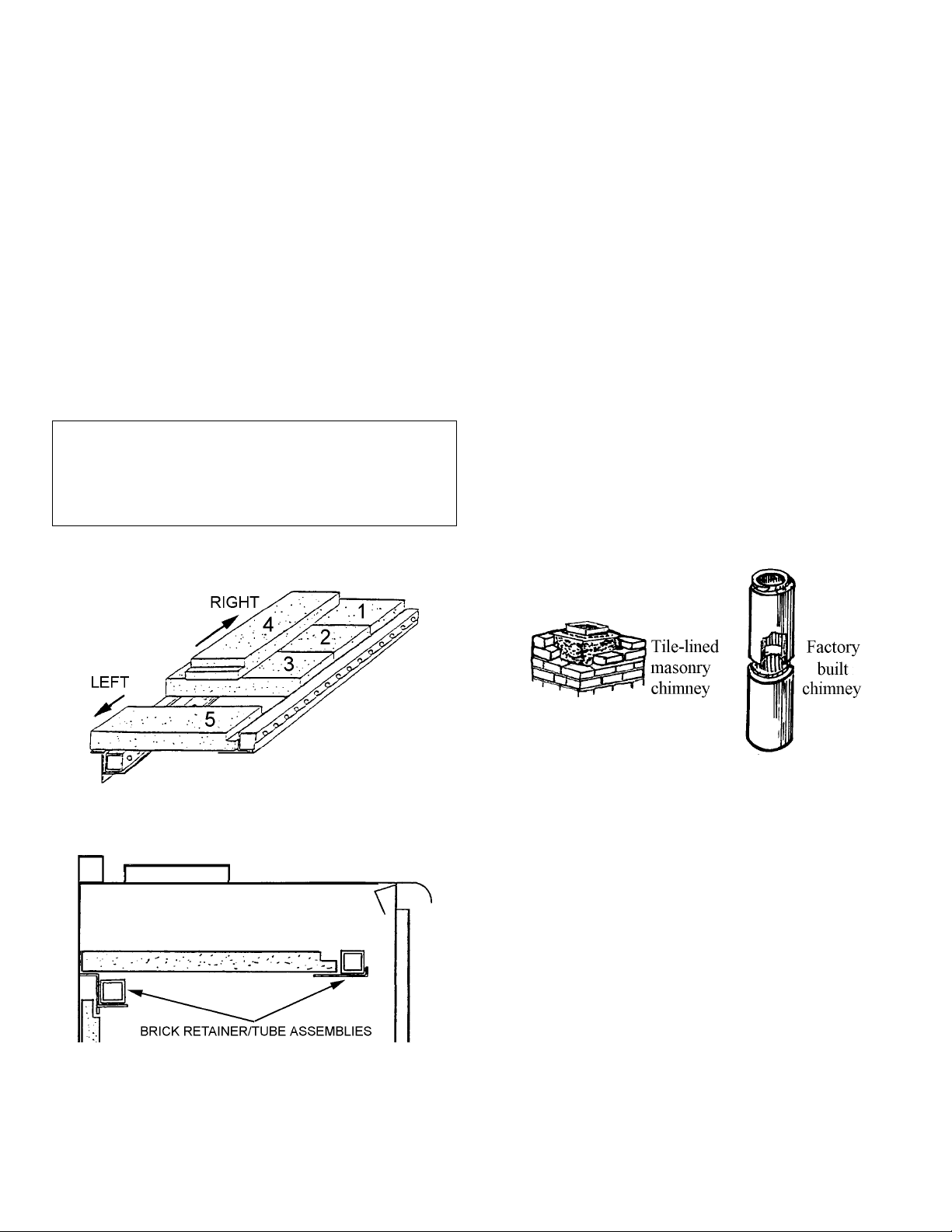
INSTALLING THE BAFFLE BRICKS
There are 2 brick retainer tube assemblies located below the ceiling of the firebox which require baffle brick
before the stove can be operated. Install the baffle brick
as follows:
1. Place the first three brick onto the brick retainers
with the notch facing up and toward the front. Next,
slide the three brick all the way to the right (as you
face the stove. See top view illustration below).
2. Place the fourth brick on top of the three brick. Position it so the notch is facing up and pointing to the
left.
3. Install the fifth brick and slide all the way to the left.
4. Rotate the fourth brick into position (notch to the
front and facing up) until it drops into place.
IMPORTANT: The baffle brick requires periodic inspection and replacement for proper operation. If
the baffle bricks are fractured or crumbling, they
should be replaced. Do not operate this appliance
without the baffle brick properly installed.
TOP VIEW OF BAFFLE BRICK
TYPES OF CHIMNEYS
The chimney is a vital part of your stove installation. A
properly built masonry chimney or a properly installed
factory built chimney will assure a consistent draft under
a variety of weather conditions (a smoking stove is usually caused by a chimney problem). The stove flue size
is 6 inches (152 mm) diameter, which is approximately
28 square inches (711 square mm) minimum. The
maximum flue size should be no more than (3)-three
times the cross sectional area of the size of the stove
flue collar. In this case, that would be no larger than a
10 inch (254 mm) diameter stack, or approximately 85
square inches (216 square cm) maximum.
All chimneys must be installed as specified by local
building codes and according to the chimney manufacturer instructions (in the case of a factory built chimney).
See the chimney manufacturer instructions for exact
specifications. Factory built chimneys must comply with
UL 103HT or ULC S629.
SIDE VIEW OF BAFFLE BRICK
PAGE 8

INSTALLATION
ACCEPTABLE CONNECTOR PIPE FOR INSTALLATIONS
For Standard Residential Clearances:
mm) minimum, single wall, 25 gage minimum thickness,
stove pipe is acceptable. Three (3) pre-drilled holes are
provided in the flue collar for fastening the pipe securely
to the stove. Use sheet metal screws to do this. Additional sections of single wall pipe should be fastened
together with at least three (3) sheet metal screws each
section. When connecting to the factory built ceiling
support package, use the manufacturer's transition
piece, usually called a dripless connector, to join single
wall pipe to their factory built chimney section.
Minimum Flue Size
and area required for the flue size is (respectively) 6
inches / 152 mm diameter, which is approximately 28
square inches / 711 square mm. The maximum flue
size should be no more than (3) three times the cross
sectional area of the size of the 6 inches / 152 mm diameter flue collar. In this case, that would be no larger
than a 10 inch (254 mm) diameter (area = approx. 85
sq. inches [216 sq. cm]).
Connection To A Factory Built Chimney
heater is to be connected to a factory-built chimney
conforming to CAN / ULC – S629, Standard for 650°C
Factory-Built Chimneys.
For Reduced Residential Clearances:
listed double wall connector pipe is acceptable. Install
any factory built brand of pipe according to the manufacturer's instructions.
: The required minimum diameter
Six 6 inch (152
: This space
Type L and
CHIMNEY INSPECTION
Existing chimneys must be inspected before installing
your stove. Consult your local building department for
chimney code requirements. A masonry chimney must
have a code approved liner. This liner must not have
broken or missing pieces. Some non-code masonry
chimneys may be brought up to code by being relined.
(Consult your dealer or qualified chimney sweep). Factory built chimneys should also be inspected, first for
creosote deposits (which should be removed), and then
for integrity of the stainless steel liner. Look for obvious
bulges in the lining which may indicate the need to replace that section (use a bright flashlight). Also, inspect
the attic to see that the chimney has proper clearance
to combustible framing members. For interior masonry
chimneys and most factory built chimneys, this must be
a (2) two inch (51 mm) air space clearance, which must
not be filled with insulation or any other material. An
exterior masonry chimney must have a (1) one inch
(25.4 mm) air space clearance.
Vapor Barrier At Chimney Penetration
Install all venting components per the Vent Manufacturers installation instructions. Ensure that there is an effective vapor barrier at the location where the chimney
penetrates to the exterior of the structure. This can be
accomplished by applying a non-hardening waterproof
sealant to the following components:
• Around the chimney at the point where the storm
collar will meet the chimney just above the Flashing.
• Along the vertical seam of the chimney pipe, where
it is exposed to the weather.
• On each nail head on the flashing.
• Around the chimney at the point where the storm
collar will meet the chimney just above the flashing.
Notes:
• On a flat or tarred and graveled roofs, nail and seal
the flat roof flashing to the roof on all sides with
roofing compound.
• Do not put screws through the flashing into the
chimney pipe.
PAGE 9
 Loading...