

Page 1
LIMITED WARRANTY
ALL MILTON PRODUCTS are manufactured to exacting standards, using the finest materials
and are GUARANTEED AGAINST ALL DEFECTS IN MATERIALS AND/OR WORKMANSHIP
for a period of one year after date of purchase. WITH PROPER CARE, THEY WILL PROVIDE
LONG AND "TROUBLE-FREE" SERVICE.
If a user feels any Milton Product, which has not been abused or misused, has not given
reasonable service, he (the user) may return that product, prepaid, to the factory. (UPS or
Parcel Post Only).
Any product, which factory inspection reveals to be defective in materials and/or workmanship
within the terms of our Limited Warranty, will be repaired or replaced, no charge, at our option.
Repairable products, which inspection reveals to be abused, misused, or worn in service, and
which are not considered expendable, will be reconditioned for a nominal service charge, and
returned to the user.
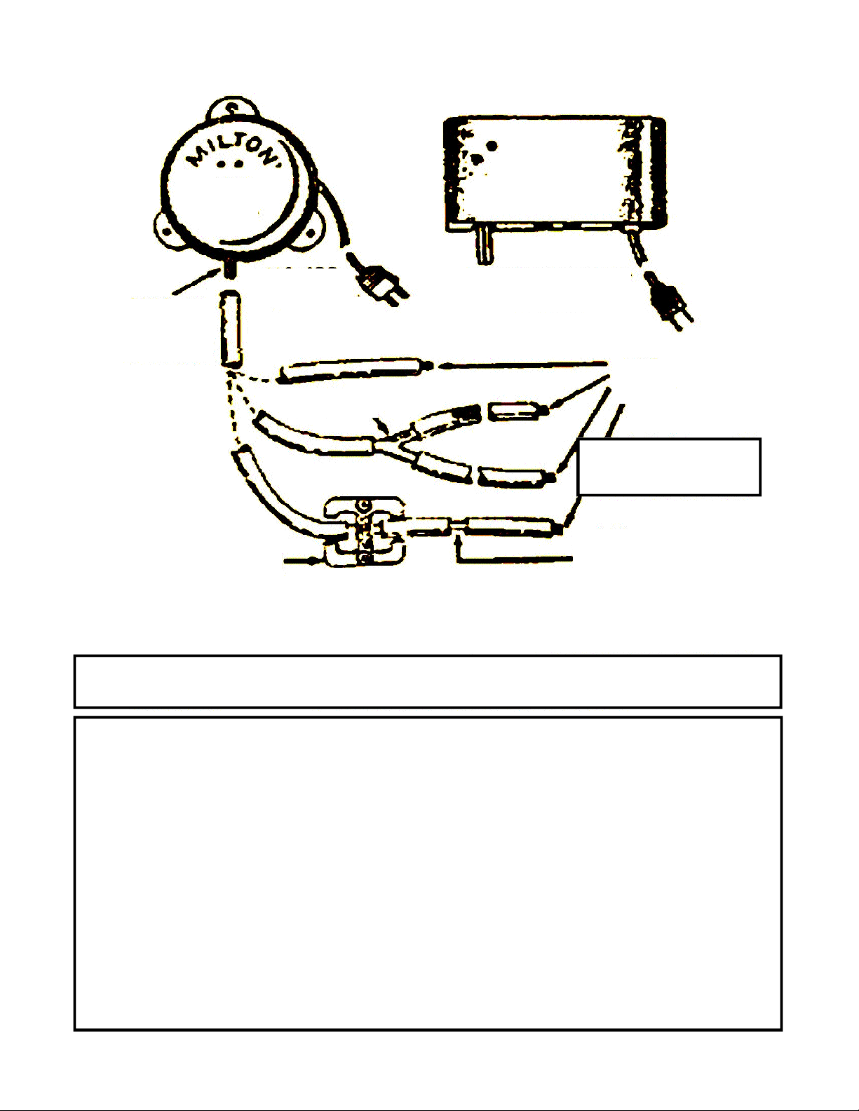
BELL OR CHIME MUST BE INSTALLED UPRIGHT.
USE ALL MOUNTING HOLES TO FASTEN.
802
CHIME
MILTON
SAME HOOK-UP
AS 805
805
BELL
110 - 120
VOLTS AC
MOUNT
MINIMUM 4 FEET
FROM GROUND
HOSE OPTIONS
807
PLUG
ALWAYS PLUG
HOSE END
817 "Y"
819
ANCHOR
810
SPLICE
USE ONLY SPECIFIED HOSE. DO NOT EXCEED 300' TOTAL LENGTH
HOSE 50 FT. - 838
HOSE 300 FT. - 839
MODELS 825, 827, 830 - SEE OTHER SIDE.
MILTON SIGNAL BELL / CHIME - INFORMATION SHEET
Page 2
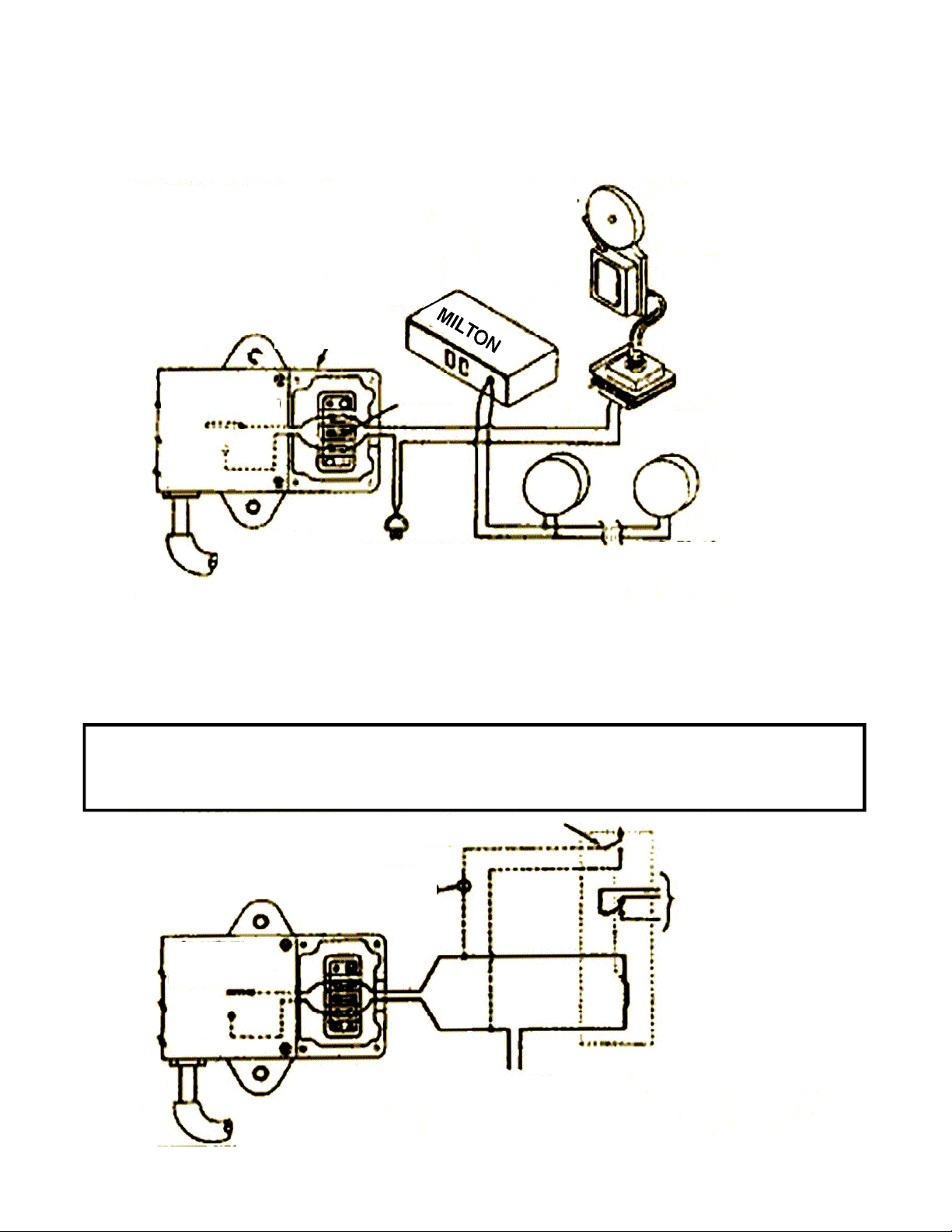
THE MILTON NO. 825 REMOTE CONTROL AIR SWITCH IS AN AIR OPERAT E D
MOMENTARY CONTACT ELECTRICAL CONTROLLER. IT WILL OPERATE ALL MILTON
REMOTE CONTROLLED SIGNALS (MODELS 827 AND 830) AS WELL AS BELLS,
BUZZERS, LIGHTS, ETC. IT WILL ALSO OPERATE RELAYS FOR INDUSTRIAL
APPLICATIONS.
ELECTRICAL RATING
0 - 240 VOLTS AC OR DC, 10 AMPS
STANDARD HOOK-UPS
FOR
MODEL 825
OPTIONAL
STANDARD
DOORBELL OR BUZZER
SECONDARY
10 VOLTS AC
OPTIONAL
830
CHIME
825
PRIMARY
110 - 125 VOLTS AC
827
BELL
8
27
BELL
MOMENTARY
AIR SWITCH
10
AMPS MAX.
REMOVE SMALL
COVER
NOT USED
SIGNAL AIR HOSE.
PLACE ACROSS
DRIVEWAY. PLUG
UNUSED END.
110 - 125 VOLTS AC
(OR 6 - 220 VOLTS AC OR DC WITH
MATCHING VOLTAGE UNITS)
This is a pictorial wiring diagram to suggest various hook-up options and to show a
typical circuit path. Any installation must be properly terminated and insulated and must
conform to all applicable codes. Consult a qualified electrician.
NOTE: The center terminal on the terminal strip can be used as a convenient tie point if
desired.
IMPORTANT:
The model 825 must always be mounted with the hose connector tube
pointing straight down. Remove plastic cap before attaching hose.
STANDARD HOOK-UPS
FOR
RELAY APPLICATIONS
LATCHING RELAY CONNECTOR
(OPTIONAL)
RESET
(OR UNLATCH)
SWITCH N.C.
TO CIRCUIT TO
BE CONTROLLED
RELAY
USER SUPPLIED
MUST MATCH
POWER SOURCE
TO RELAY
POWER SOURCE
0 - 240 VOLTS AC OR DC
SIGNAL AIR HOSE.
PLUG UNUSED END.
10
AMPS MAX.
MOMENTARY
AIR SWITCH
(NORMALLY OPEN)
(NORMALLY OPEN)
STANDARD BELL
TRANSFORMER
825
UP TO 10 ADDITIONAL
UNITS (OPTIONAL)
 Loading...