

Milnor 30022F, 30022F8J, 30022F8P, 30022F8W Service Manual

Published Manual Number/ECN: MAP30FXXAE/2000184N
• Publishing System: TPAS
• Access date: 04/26/2000
• Document ECN's: Latest Available
Service—
30022Fxx
Washer-Extractors
PELLERIN MILNOR CORPORATION POST OFFICE BOX 400, KENNER, LOUISIANA 70063-0400, U.S.A.

Please Read
About the Manual Identifying Information on the Cover
The front cover displays pertinent identifying information for this manual. Most important, are
the published manual number (part number) /ECN (date code). Generally, when a replacement
manual is furnished, it will have the same published manual number, but the latest available
ECN. This provides the user with the latest information applicable to his machine. Similarly all
documents comprising the manual will be the latest available as of the date the manual was
printed, even though older ECN dates for those documents may be listed in the table of
contents.
When communicating with the Milnor factory regarding this manual, please also provide the
other identifying information shown on the cover, including the publishing system, access date,
and whether the document ECN’s are the latest available or exact.
References to Yellow Troubleshooting Pages
This manual may contain references to “yellow pages.” Although the pages containing
troubleshooting procedures are no longer printed on yellow paper, troubleshooting instructions, if
any, will be contained in the easily located “Troubleshooting” chapter or section. See the table of
contents.
Trademarks of Pellerin Milnor Corporation
The following, some of which may be used in this manual, are trademarks of Pellerin Milnor
Corporation:
Ampsaver
Autolint
Auto-Purge
®
®
®
Autovac E-P Plus
®
CBW
Dye-Extractor® Hands-Off
Dyextractor® Hydro-Cushion
®
Gear Guardian
Mildata
®
®
®
®
®
Milnet
Milnor
®
Staph-Guard
System 4
Miltrac System 7
Miltron Totaltrol
®
®
®
®
Comments and Suggestions
Help us to improve this manual by sending your comments to:
Pellerin Milnor Corporation
Attn: Technical Publications
P. O. Box 400
Kenner, LA 70063-0400
Fax: (504) 469-1849

Table of Contents
for MAP30FXXAE/2000184N
30022Fxx Washer-Extractors
Page Description Document/ECN
1 About This Manual MHP30FXXAE/9541AV
3 Warranty BMP720097/92732A
5 How to Order Parts BMP720097R/72332A
6 Installation and Service Safety for Suspended
Washer-Extractors and Centrifugal Extractors MSINA405AE/9909AV
11 About the Forces Transmitted by Milnor Washer-Extractors MSIN0210AE/9330AV
13 Glossary of Tag Illustrations - Q-Style Washer-Extractors MSIUUQTGAE/9449CV
17 Section 1: Service and Maintenance
18 Preventive Maintenance for the 30022 Suspended
Washer-Extractor MSSMA424AE/9852AV
23 Replacing 30Fxx Main Bearings MSSM0261BE/9933AV
28 Replacing Isolator Cushions MSSM0260AE/9834AV
29 Fastener Torque Requirements MSSM0101CE/9906AV
49 Section 2: Covers, Safety and Shipping Brackets
50 Installation Guards & Covers - 30022F8J, F8P, F8W BMP940036/94177V
51 Isolator Shipping Brackets - 30022F8J, F8P, F8W BMP940045/94203V
53 Section 3: Frame and Housing Assemblies
54 House and Shell Vent Installation - 30022F8J, F8P, F8W BMP940043/94201V
57 Section 4: Suspension
58 Isolator Installation - 30022F8J, F8P, F8W BMP940039/94192V
60 Isolator Assemblies (5.75" Diameter Springs)
- 30022F8J, F8P, F8W BMP940040/97042V
61 Installation Shock Absorber - 30022F8J, F8P, F8W BMP940044/94203V
63 Excursion Switch - 3022F8J, F8P, F8W BMP940035/94177V
65 Section 5: Drive Assemblies
66 Installation Drive Base Assembly - 30022F8J, F8P, F8W BMP940034/94177V
68 Main Bearing Installation - 3022F8J, F8P, F8W BMP940032/98053V
70 Main Bearing - 30022F8P, H7x BMP980022/99051V
72 Cylinder Installation - 30022F8J, F8P, F8W BMP940033/94162V
73 Section 6: Shell and Door Assemblies
74 Installation Shellfront - 30022F8J, F8P, F8W BMP940046/94223V
76 Door Assembly - 30015 & 30020 Rigid Mount
Washer-Extractors BMP920009/94491V
78 Interlock Assembly BMP750046/97341V
81 Section 7: Water and Steam Piping and
Assemblies
82 Water Inlet Assembly & Installation - 30022F8J, F8P, F8W BMP940057/94217V
83 Hays Electric Inlet Valves BMP700710/96081V

Table of Contents, cont.
Page Description Document/ECN
85 Pressure Regulators BMP900031/96081V
87 Installation Drain Assembly - 30022F8J, F8P, F8W BMP940055/94212V
88 Electric Drain Valve - 30022 Rigid Mount Washer-
Extractors BMP920017/93251V
89 Section 8: Chemical Supply Devices
90 Dry Soap Chute BMP940037/98183V
92 Soap Manifold Assembly BMP940038/98183V
93 Assembly 6 Valve Soap Manifold - 30022F8J, F8P, F8W BMP940052/94202V
95 5 Compartment Dry Supply Assembly & Installation
- 30022F8J, F8P, F8W BMP940053/94202V
96 Installation Peristaltic Soap Chute - 30022F8J, F8P, F8W BMP940050/94202V

MHP30FXXAE/9541AV (1 of 1)
ABOUT THIS MANUAL
Scope
—This instruction manual is intended to provide preventive maintenance procedures, service procedures and mechanical parts identification for all Milnor® 30022Fxx suspended washer-extractors. Measurements
are in common US and metric units unless otherwi se noted. Always us e new fast eners when repl acing or repairing parts. See the safety manual for safety inst ructions before installing, servici ng, or operating this machine. See
the installation guide for facility requirements, installation instructions, and assembly instructions. See the operator guide for operator instructions. See the reference manual for programming, operating, and trouble shooting
instructions. See the schematic manual for electrical parts identification and electrical trouble shooting.
Trademarks of Pellerin Milnor Corporation
—The following, some of which may be used in this
publication, are trademarks of Pellerin Milnor Corporation:
Ampsaver
®
Autolint
®
Auto-Purge
®
Autovac
CBW
®
Dye-Extractor
®
Dyextractor
®
E-P Plus
®
Gear Guardian
®
Hands-Off
®
Hydro-Cushion
®
Mildata
®
Milnet
®
Milnor
®
Miltrac
Miltron
Staph-Guard
®
System 4
®
System 7
®
Totaltrol
®
Manual Number/Date Code (When To Discard or Save)
—The manual number/date code is
located on the inside front cover, upper right corner just above the manual name. Whenever the manual is reprinted with new information, part of this number changes. If the date code after the “/” changes, the new
version applies to all machines covered by th e old version, b ut is improved — thus the old version can be
discarded. If the manual number before the “/” changes, the new manual covers only new machin es. Ex-
ample: Discard MATMODELAE/8739CV when MATMODELAE/8739DV is received (minor improvements).
Also, discard MATMODELAE/87
39D
V when MATMODELAE/87
46A
V is received (major improvements).
But keep MATMODELAE/8746FV when MATMODELBE/8815AV is received, since the new manual no
longer applies to machines originally shipped with the old manual.
Documents and Change Bars
—The individual documents comprising this manual use the same revision criteria as the manual. Text documents also display change bars. Example: When section
MSOP0599AE/9135BV becomes MSOP0599AE/9135CV, change bars with the letter “C” appear next to all
changes for this revision. For a major rewrite (e.g., MSOP0599AE/92
26A
V), all change bars are deleted.
For Assistance
—Please call:
Pellerin Milnor Corporation
Attn: Service Department
P. O. Box 400
Kenner, LA 70063-0400
Phone: (504) 467-9591
Fax: (504) 467-9777


3(//(5,10,/125&25325$7,21
/,0,7('67$1'$5':$55$17<
We warrant to the original purchaser that MILNOR machines including electronic
hardware/software (hereafter referred to as “equipment”), will be free from defects in material
and workmanship for a period of one year from the date of shipment from our factory with no
operating hour limitation. This warranty is contingent upon the equipment being installed,
operated and serviced as specified in the operating manual supplied with the equipment, and
operated under normal conditions by competent operators.
Providing we receive written notification of a warranted defect within 30 days of its discovery,
we will – at our option – repair or replace the defective part or parts, FOB our factory. We
retain the right to require inspection of the parts claimed defective in our factory prior to
repairing or replacing same. We will not be responsible, or in any way liable, for unauthorized
repairs or service to our equipment, and this warranty shall be void if the equipment is repaired
or altered in any way without MILNOR’s written consent.
Parts which require routine replacement due to normal wear – such as gaskets, contact points,
brake and clutch linings and similar parts – are not covered by this warranty, nor are parts
damaged by exposure to weather or to chemicals.
We reserve the right to make changes in the design and/or construction of our equipment
(including purchased components) without obligation to change any equipment previously
supplied.
ANY SALE OR FURNISHING OF ANY EQUIPMENT BY MILNOR IS MADE ONLY UPON
THE EXPRESS UNDERSTANDING THAT MILNOR MAKES NO EXPRESSED OR IMPLIED
WARRANTIES OF MERCHANTABILITY OR FITNESS FOR ANY PARTICULAR USE OR
PURPOSE. MILNOR WILL NOT BE RESPONSIBLE FOR ANY COSTS OR DAMAGES
ACTUALLY INCURRED OR REQUIRED AS A RESULT OF: THE FAILURE OF ANY OTHER
PERSON OR ENTITY TO PERFORM ITS RESPONSIBILITIES, FIRE OR OTHER HAZARD,
ACCIDENT, IMPROPER STORAGE, MISUSE, NEGLECT, POWER OR ENVIRONMENTAL
CONTROL MALFUNCTIONS, DAMAGE FROM LIQUIDS, OR ANY OTHER CAUSE BEYOND
THE NORMAL RANGE OF USE. REGARDLESS OF HOW CAUSED, IN NO EVENT SHALL
MILNOR BE LIABLE FOR SPECIAL, INDIRECT, PUNITIVE, LIQUIDATED, OR
CONSEQUENTIAL COSTS OR DAMAGES, OR ANY COSTS OR DAMAGES WHATSOEVER
WHICH EXCEED THE PRICE PAID TO MILNOR FOR THE EQUIPMENT IT SELLS OR
FURNISHES.
WE NEITHER ASSUME, NOR AUTHORIZE ANY EMPLOYEE OR OTHER PERSON TO
ASSUME FOR US, ANY OTHER RESPONSIBILITY AND/OR LIABILITY IN CONNECTION
WITH THE SALE OR FURNISHING OF OUR EQUIPMENT TO ANY BUYER.
BMP720097
92732A


How to order repair parts
Repair parts may be ordered either from the authorized dealer who sold you this
machine, or directly from the MILNOR factory. In most cases, your dealer will
have these parts in stock.
When ordering parts, please be sure to give us the following in formation:
1. Model and serial number of the machine for which the parts are required
2. Part number
3. Name of the part
4. Quantity needed
5. Method of shipment des ired
6. In correspondence regarding motors or electrical controls, please include all
nameplate data, including wiring diagram number and the make or
manufacturer of the motor or controls.
All parts will be shipped C.O.D. transportation charges collect on ly.
Please read this manual
It is strongly recommended that you read the installation and operating manual
before attempting to install or operate your machine. We suggest that this manual
be kept in your business office so that it will not become lo st.
PELLERIN MILNOR CORPORATION
32%2;.(11(5/$ 86$
FAX: Administration 504/468-9307, Engineering 504/469-1849, Service 504/469-9777
BMP720097R
72332A

MSINA405AE/9909AV
ÈINSTALLATION AND SERVICE SAFETY FOR SUSPENDED
WASHER-EXTRACTORS AND CENTRIFUGAL EXTRACTORS
ÊGeneral Safety Requirements
(specific warnings, next page and throughout manual)
Incorrect installation, neglected preventive maintenance, abuse, and/or improper repairs or changes to the
machine can cause unsafe operation and personal injuries, such as multiple fractures, amputations, or death. The
owner or his selected representative ( owner/user) is responsibl e for understanding and ensuring the proper operation
and maintenance of the machine. The owner/user must familiarize himself with the contents of all machine instruction manuals. The owner/user should direct any questions about these instructions to a Milnor® dealer or the Milnor® Service department.
Most regulatory authorities (including OSHA in the USA) hold the owner/user ultimately responsible for
maintaining a safe working environment. Therefore, the owner/user must do the following:
• recognize all foreseeable safety hazards within his facility and take actions to protect his personnel,
equipment, and facility
• require that personnel are familiar with all functional and safety aspects of the machine
• ensure safety devices installed on the machine are in place and properly maintained
• ensure all machine parts and assemblies are properly maintained.
ËLaundry Facility
—Provide a supporting floor that is strong and rigid enough to support--with a reasonable
safety factor and without undue or objectionable deflection--the weight of the fully loaded machine and the forces
transmitted by it during operation. (For washer-extractors, see “ABOUT THE FORCES TRANSMITTED BY MILNOR® WASHER-EXTRACTORS.”) Provide sufficient clearance for machine movement. Provide any safety
guards, fences, restraints, devices, and verbal and/or posted restrictions necessary to prevent personnel, machines,
or other moving machinery from accessing the machine or its path. Provide adequate ventilation to carry away heat
and vapors. Ensure service connections to installed machines meet local and national safety standards, especially
regarding the electrical disconnect (see the National Electric C ode). Prominently pos t safety inform ation, including
signs showing the source of electrical disconnect.
ËPersonnel
—Inform personnel about hazard avoidance and the importance of care and common sense. Provide
personnel with the safety and operating instructions that apply to them. Verify that pers onnel use proper safety and
operating procedures. Verify that personnel understand and abide by point-of-hazard tags on the machine and procedure-specific precautions in the instruction manuals.
ËSafety Devices
—Ensure that no one eliminates or disables any safet y device on the machine or in this facil ity.
Do not allow machine to be used with any missing guard or cover. Service any failing or malfunctioning device
before operating the machine.
ËMaintenance
—Ensure the machine is inspected and serviced in accordance with the norms of good practice and
with the preventive maintenance schedule. Replace belts, pulleys, brake shoes/disks, clutch plates/tires, rollers,
seals, alignment guides, etc. before they are severely worn. Immediately investigate any evidence of impending
failure and make needed repairs (e.g., cylinder, shell, or frame cracks; drive components such as motors, gear boxes,
bearings, etc., whining, grinding, smoking, or becoming abnormally hot; bending or cracking of cylinder, shell,
frame, etc.; leaking seals, hoses, valves, etc.) Do not permit service or maintenance by unqualified personnel.
READ BEFORE INSTALLING MACHINE!
ÊHazards During Installation
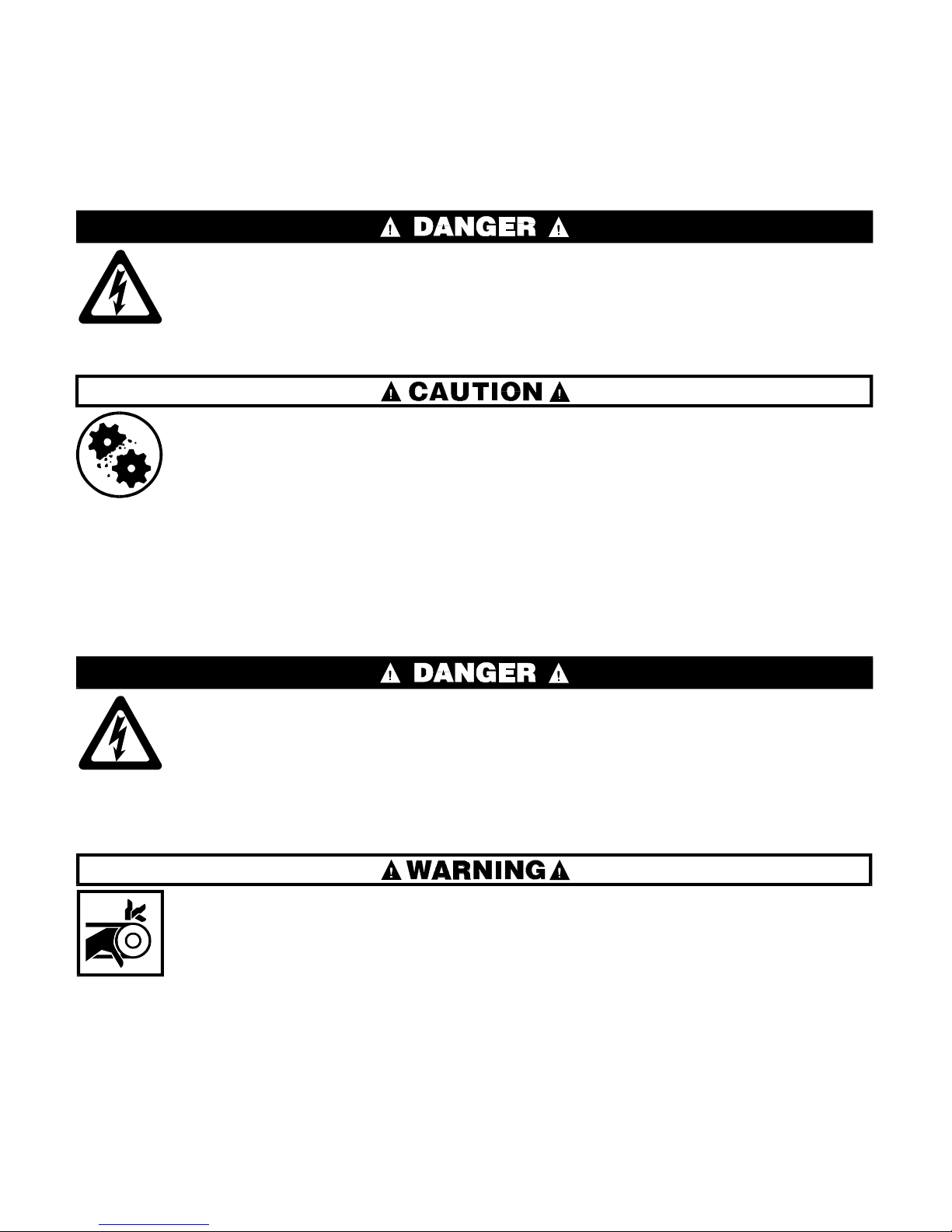
ELECTROCUTION HAZARD—Contact with high voltages can kill or seriously
injure you.
☞ All electrical connections must be made by a competent electrician.
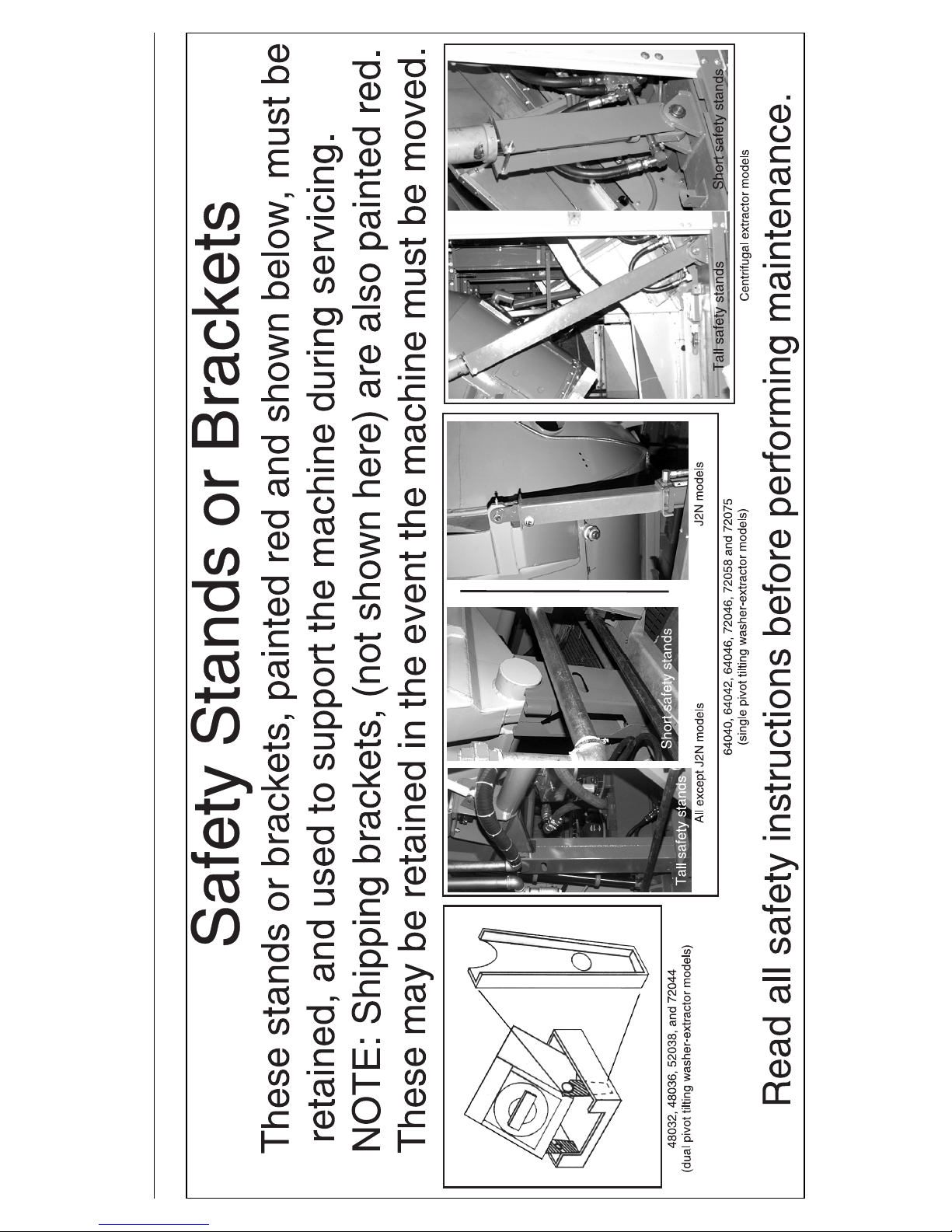
EQUIPMENT DAMAGE HAZARD—Machine can be damaged if shipping restraints are improperly utilized. These include various bolts, brackets, and
safety stands (painted red), brake blocks and the vibration safety switch (tie
wrapped).
☞ DO NOT remove shipping restraints until installation is complete.
☞ DO remove all shipping restraints before operating machine.
ÊHazards During Service and Maintenance
ELECTROCUTION HAZARD—High voltage is present inside electric boxes, motors and many other components. Power switches on machine control panels
disable only control circuit power in certain boxes. You can be killed or seriously injured on contact with high voltage.
☞ Lock OFF and tag out power at the wall di sconnect before ser vici ng, except w her e spe -
cifically instructed otherwise in this manual.
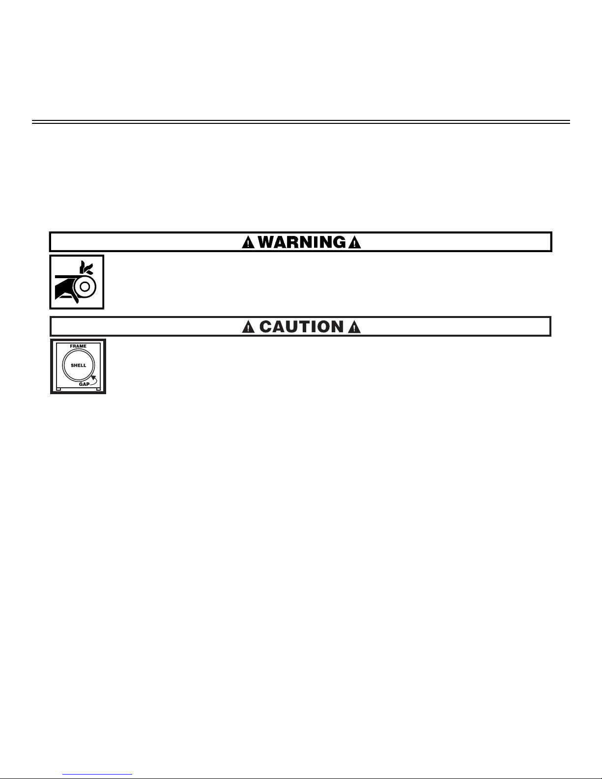
ENTANGLE AND CRUSH HAZARD—Belts and pulleys can entangle and crush
body parts.
☞ Lock OFF and tag out power at the wall disconnect before servicing, except
where specifically instructed otherwise in this manual.
☞ Insure belt guards are in place during service procedures.
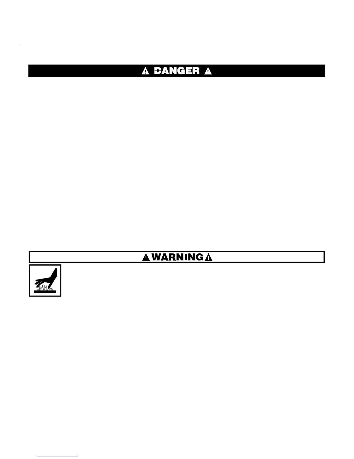
MULTIPLE HAZARDS—Failure to maintain machine in proper working order can result in
fatal or serious injury to operators and/or damage to property. DO NOT permit operation
under any of the following circumstances:
☞ Malfunctioning door interlock mechanism.
☞ Malfunctioning limit switches.
☞ Malfunctioning two hand inching.
☞ Any evidence of cylinder damage.
☞ Missing or removed guards, covers, or side panels.
☞ Malfunctioning tilting components, including but not limited to safety limit switches,
electrical interlocks, and operator controls.
☞ If any of these conditions occur:
• The machine makes a sound like skidding automobile tires as it comes out of extract.
• The wash or drain clutch does not disengage or it reengages during extract.
• V-bel ts jum p off at the start of, during, or at the end of extract.
• A strange whining sound occurs at any time during extract.
BURN HAZARD — Machines equipped with heat exchangers and their associated piping may be hot enough to burn body parts on contact.
☞ Provide safety guards, fences, restraints, or covers as required to isolate hot
surfaces.
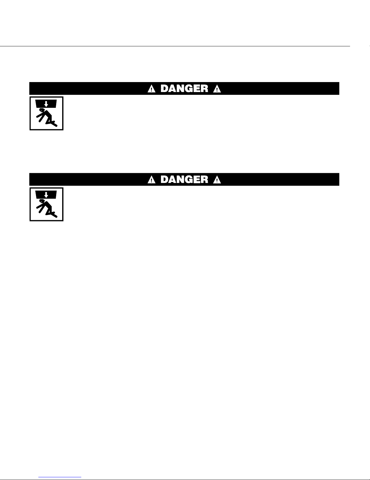
ÊAdditional Hazards During Tilting Machine Maintenance
CRUSH/SEVER HAZARD—Tilting mechanisms can crush or sever parts of your
body caught in them.
☞ Install the safety stands before performing maintenance under a tilted ma-
chine.
☞ NEVER test or operate (manually or automatically) any machine function
with any portion of a person’s body under the tilted machine—even if the
safety stands are inst al le d.
CRUSH/SEVER HAZARD—Tilting machines with tilt wheels/cradles may lunge for ward or rearward and even fal l over if the tilt whee ls at the non-tilted end are raised
out of their cradles—killing/ injuring personnel and/or damaging property.
☞ NEVER manually tilt (lift) both ends of the machine at the same time. One end must
always be seated in it s cradle.
☞ ALWAYS visually inspect the tilt wheels to be sure they are all fully seated in their cra-
dles before each manual tilt up.
☞ Hydraulic valve manual operation must be done by trained competent maintenance per-
sonnel who thoroughly understand the system and all the consequences of manual
operations.
☞ ALWAYS understand beforehand all the consequences of manually operating hydraulic
valves.
☞ NEVER permit operation with malfunctioning tilt limit switches.
INSTALLATION AND SERVICE SAFETY FOR SUSPENDED
WASHER-EXTRACTORS AND CENTRIFUGAL EXTRACTORS MSINA405AE/9909AV (3 of 3)

MSIN0210AE/9330AV
ÈABOUT THE FORCES TRANSMITTED
BY MILNOR
®
WASHER-EXTRACTORS
During both washing and extracting, all washer- extractors transmit both static and dynamic or cyclic forces
to the floor, to the foundation, or to any other supporting structure. During washing, the impact of the goods as they
drop imparts forces which are quite difficult to quantify. Size for size, both rigid and flexibly-mounted machines
transmit approximately the same forces during washing. During extracting, rigi d machines transmit forces up to 30
times greater than equivalent flexibly-mounted models. The actual magnitude of these forces vary—depending on
the machine size; the final extraction speed; the amount, condition and type of goods being processed; the liquor
level and chemical conditions in the bath preceding extraction; and on several other factors. Esti mates of t he maximum force normally encountered are available for each Milnor® model and size upon request. Floor or foundation
sizes shown on any Milnor® document are only for on-grade situations based only on previous experience without
implying any warranty, obligation, or responsibility on our part.
ËRigid Machines
—Size for size, rigid washer-extractors naturally require a stronger, more ri gid floor, foundation or other supporting structure than flexibly-mounted models. Providing the supporting soil under the slab is itself
strong and rigid enough and has not subsided to leave the floor slab suspended without support, on grade installations can often be made directly to an existing floor slab if it has sufficient strength and rigidity to safely withstand
our published forces without transmitting undue vibrat ion. If the subsoil has subs ided, or if the floor s lab itself has
insufficient strength and rigidity, a deeper foundation, poured as to become monolithic with the floor slab, may be
required. Support piles may even be required if the subsoil itself is “springy” (i.e., if its resonant frequency is near
the machine’s operating speed). Above grade installations of rigid machines also require a sufficiently strong and
rigid floor or other supporting structure as described below.
ËFlexibly-Mounted Machines
—Size for size, flexibly-mounted machines generally do not require as
strong a floor, foundation, or other supporting structure as do rigid machines . However, a floor or other supporting
structure having sufficient strength and rigidity (as described below) is nonetheles s vitally important for these models as well.
ËHow Strong and Rigid?
—Many USA building codes specify that laundry floors must have a mi nimum live
load capability of 150 pounds per square foot (732 kg per square m eter). However, even compliance with t his or any
other standard does not necessarily guarantee sufficient rigidity. In any event, it is the sole responsibility of the
owner/user to assure that the floor and/or any other supporting structure exceeds not only all applicable building
codes, but also that the floor and/or any other supporting structure for each washer-extractor or group of washerextractors actually has sufficient strength and rigidity, plus a reasonable factor of safety for both, to support the
weight of all the fully loaded machine(s) including the weight of t he water and goods, and includi ng the published
360o rotating sinusoidal RMS forces that are transmitted by the machine(s). Moreover, the floor, foundation, or
other supporting structure must have sufficient rigi dity (i.e. a natural or resonant frequency many ti mes greater than
the machine speed with a reasonable factor of safety); otherwise, the ment ioned 360o rotating sinusoidal RMS
forces can be multiplied and magnified many times. It is especially important to consider all potential vibration
problems that might occur due to all possible combinations of forcing frequencies (rotating speeds) of the machine(s) compared to the natural frequencies of the floor and/or any other supporting structure(s). A qualified soil
and/or structural engineer must be engaged for this purpose.

FIGURE 1 above is intended to depict both on-grade and above grade installations and are equally applicable to
flexibly-mounted washer-extractors, as well as to rigid models installed either directly on a floor slab or on a foundation poured integrally with the slab. Current machine data is available from Milnor® upon request. All data is
subject to change without notice and may have changed since last printed. It is the sole responsibility of every
potential owner to obtain written confirmation that any data furnished by Milnor® applies for the model(s) and serial
number(s) of the specific machine(s).
ÎFIGURE 1
(MSIN0210AE)
ÎHow Rotating Forces Act on the Foundation
<B8DD@C604(##(2E
7\_ccQbi_VDQW9\\ecdbQdY_^c±
ACdi\UGQcXUb5hdbQSd_bc
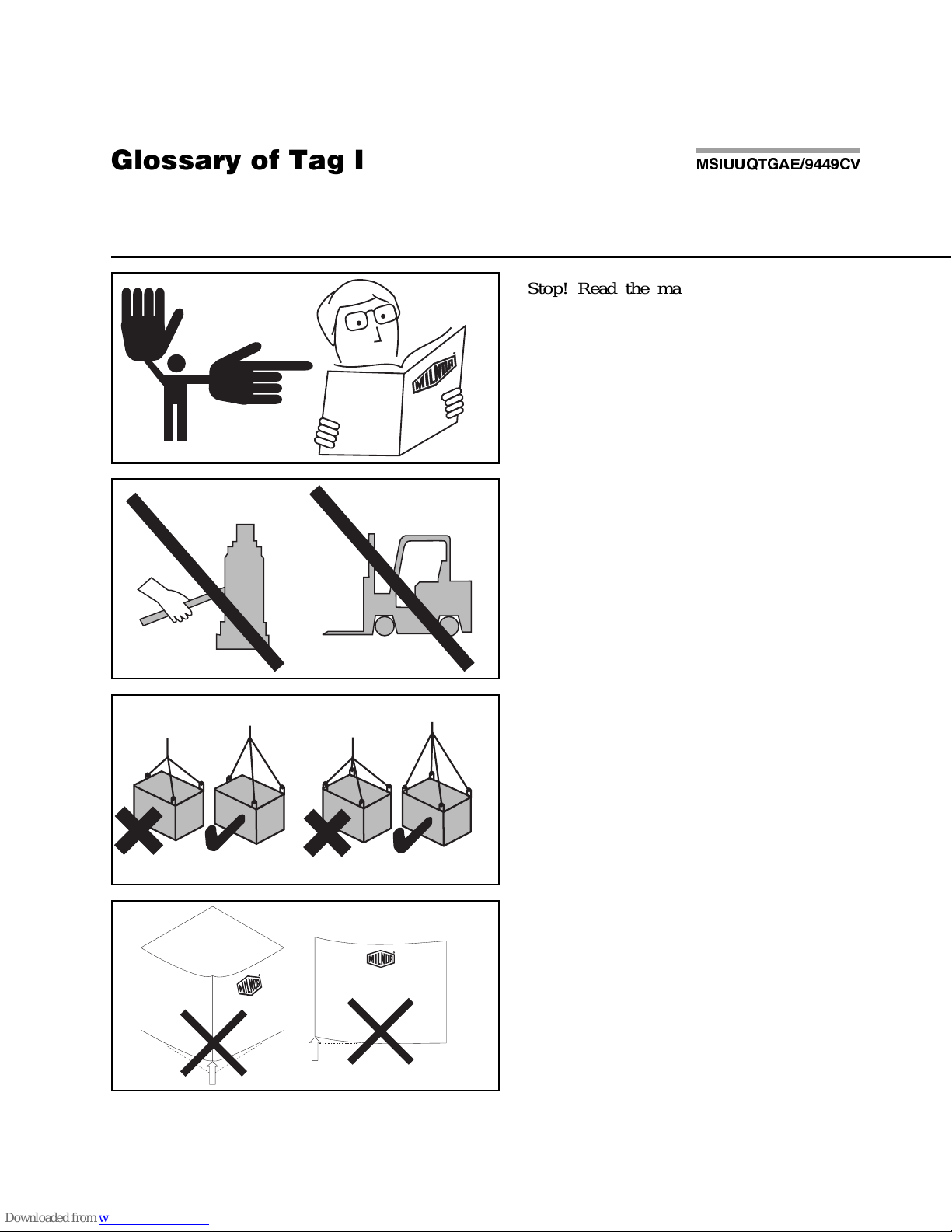
Illustration Explanation Illustration Explanation
Stop! Read the manual first for complete
instructions before continuing.
Do not jack the machine here.
Do not lift the machine here.
Use three point or four point lifting as
determined by the lifting eyes furnished. Rig
the load using lifting cables of sufficient size
and length to ensure cables are not
over-stressed.
Do not lift the machine from one corner or one
side edge.
Do not start this machine until the packing
materials, lifting brackets, etc. with this tag
attached or behind this panel are removed.
These materials are painted red. Safety stands
or brackets (also painted red) may be provided
with this machine. Do not discard safety
stands or brackets
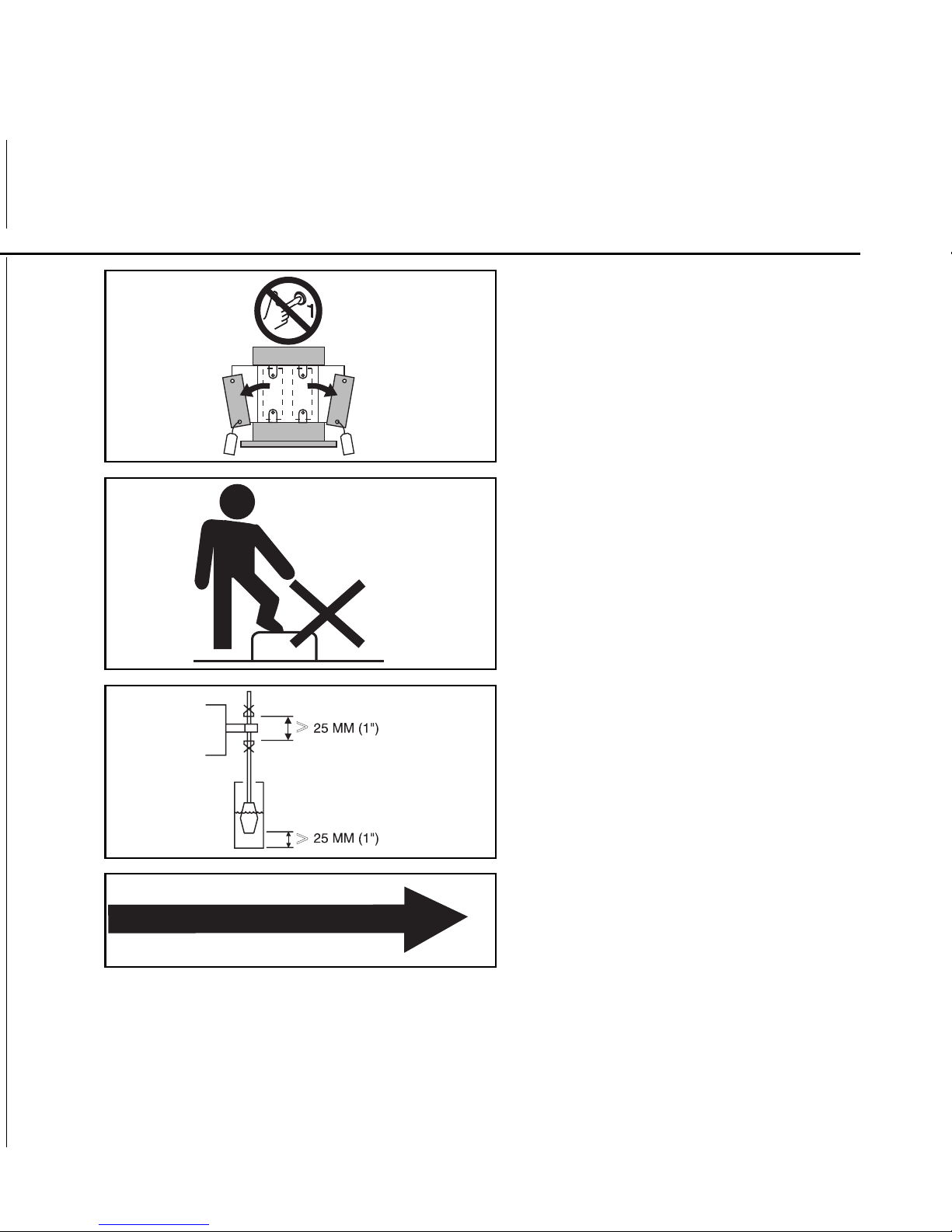
Do not step or stand on this machine part.
Maintain a 25 mm. (1") minimum clearance
between float clips. Set "low level" so that the
bottom of the float is always at least 25mm
(1") above the bottom of the float tube.
This motor or pump should rotate in the
direction of the arrow.
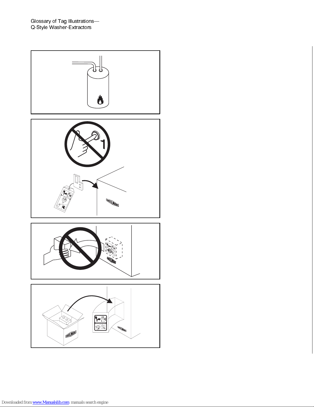
This is the hot water inlet.
Do not start this machine until the part with
this tag is installed on the machine.
Do not remove this component from the
machine.
Install the appropriate part here before
operating the machine.
7\_ccQbi _V DQW 9\\ecdbQdY_^c±
ACdi\U GQcXUb5hdbQSd_bc =C9EEAD715)$$)3F " "
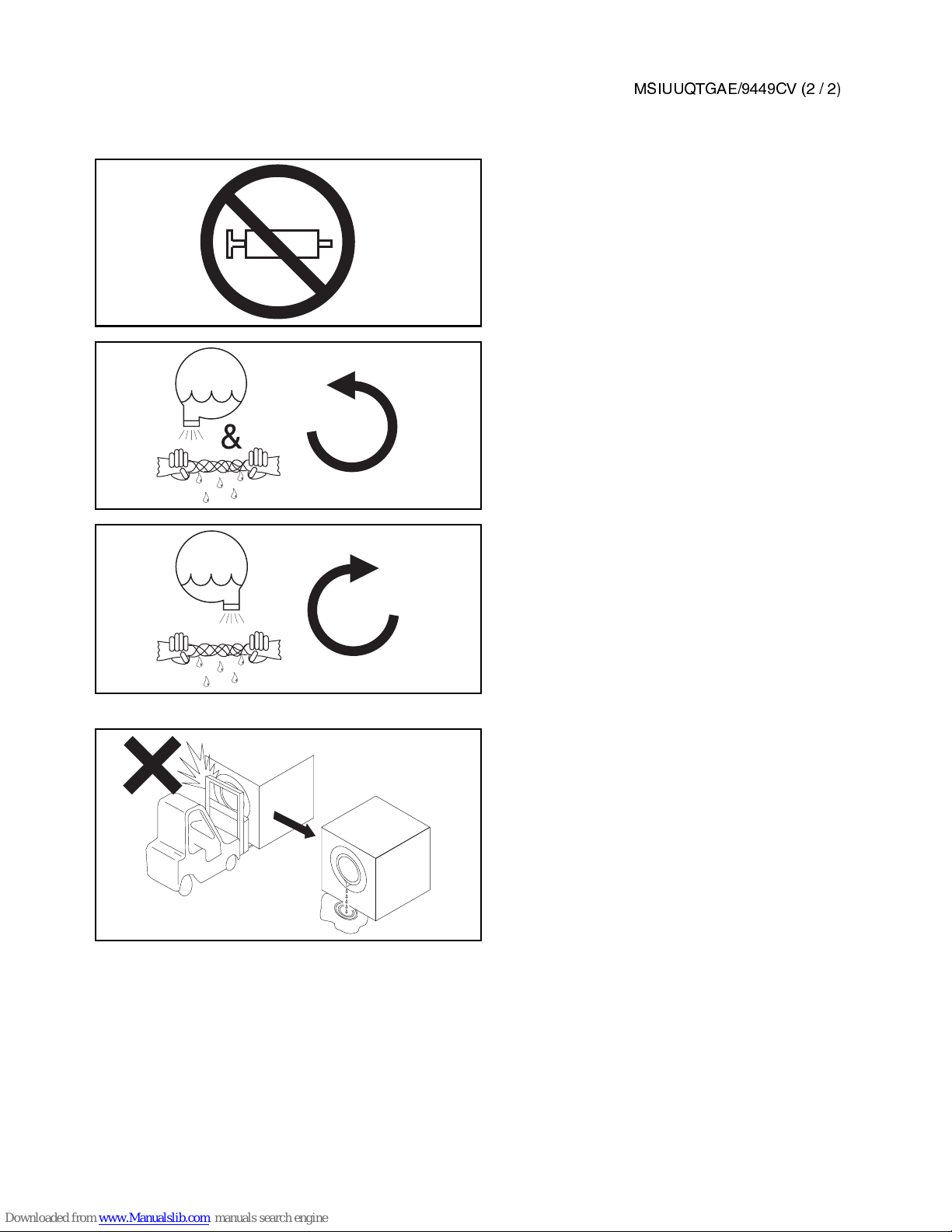
Do not pump grease here.
During drain and extract, the cylinder must
rotate counterclockwise when viewed from
here.
During drain and extract, the cylinder must
rotate clockwise when viewed from here.
Do not strike shell front of washer-extractors
during fork lifting. Striking shell front will
cause door to leak.
&

Section 1
Service and Maintenance
MSSMA424AE/9852AV
ÈPREVENTIVE MAINTENANCE FOR THE
30022 SUSPENDED WASHER-EXTRACTOR
As required by the warranty and to achieve optimum performance and service life from Milnor®washer-
extractors, the schedules, instructions, and precautions herein must be strictly followed.
ÊMain Bearing Housing Preventive Maintenance
ENTANGLE AND CRUSH HAZARD—Belts and pulleys can entangle and crush
body parts.
☞ Lock OFF and tag out power at the wall disconnect before servicing.
PINCH HAZARD—Vibrating cylinder will pinch fingers caught between shell
and frame.
☞ NEVER place fingers in gap between shell and frame.
ÊLubrication Procedures
1. Remove the rear panel.
2. Remove the drain plug on the bottom of the main bearing housing and allow the bearing housing to drain
completely. Inspect the leak-off, drained oil, and magnetic drain plug for water and/or metal particles. Water
and/or metal particles can indicate worn or damaged seals and bearings. Reinstall the drain plug.
3. After locating the oil fill plug, refill the bearing housing following lubrication specifications.
4. Reinstall the fill plug and clean excess lubricant from the machine.
ÏPreventive Maintenance Schedule
Component Action Frequency:
Monthly
(See NOTE)
= M
Every four months = F
Annually = A
Specifications
Additional Information
Main bearing
housing
Change lubricant, 22 US ounces
(0.65 liter).
FIGURE 1 (Item 2)
F
Shell Morlina
ISO 220 (SAE 50)
or equivalent
Water seals Slowly grease at one location until
grease seeps from grease relief.
FIGURES 2, 3, and
BMP980022
M Shell Alvania EP LF
(or equivalent)
Foundation bolts Check bolt tightness and wear.
Adjust or replace if necessary.
Dimensional drawing F
Drive train
Check belt tension and pulleys
for wear. Replace if necessary.
FIGURES 1 (Item 1), 6,
and 8 F
See “Testing Belt
Tension” in this section.
Isolators
Check cushions for cracks and
deterioration (eight locations).
FIGURE 4
(Items 1 and 2)
M
Check oil levels. F See the lubricant
specification for main
bearing housing above.
Replace oil, 3.5 US ounces
(0.1 liter) per isolator.
A
Shocks Check for oil leaks, replace
as required (two locations).
FIGURE 4 (Item 3) F
Peristaltic supply
(if so equipped)
Check for leaks, observe operation. F
Cooldown vernier
valve (if equipped)
Verify setting. Adjust if required. FIGURE 5 F
Flushing supply
injector
(if so equipped)
Inspect and clean the strainers in
supply injector water valves and
each compartment.
See “Bleach Note” in
this section. F
Inverter fans
and vents
Vacuum out inverter vents and
verify fan operation.
FIGURE 7 M
Steam strainer
(if so equipped)
Inspect and clean strainer. F
NOTE: MONTHLY/200 HOURS= Once a month or once every 200 operating hours, whichever comes first.
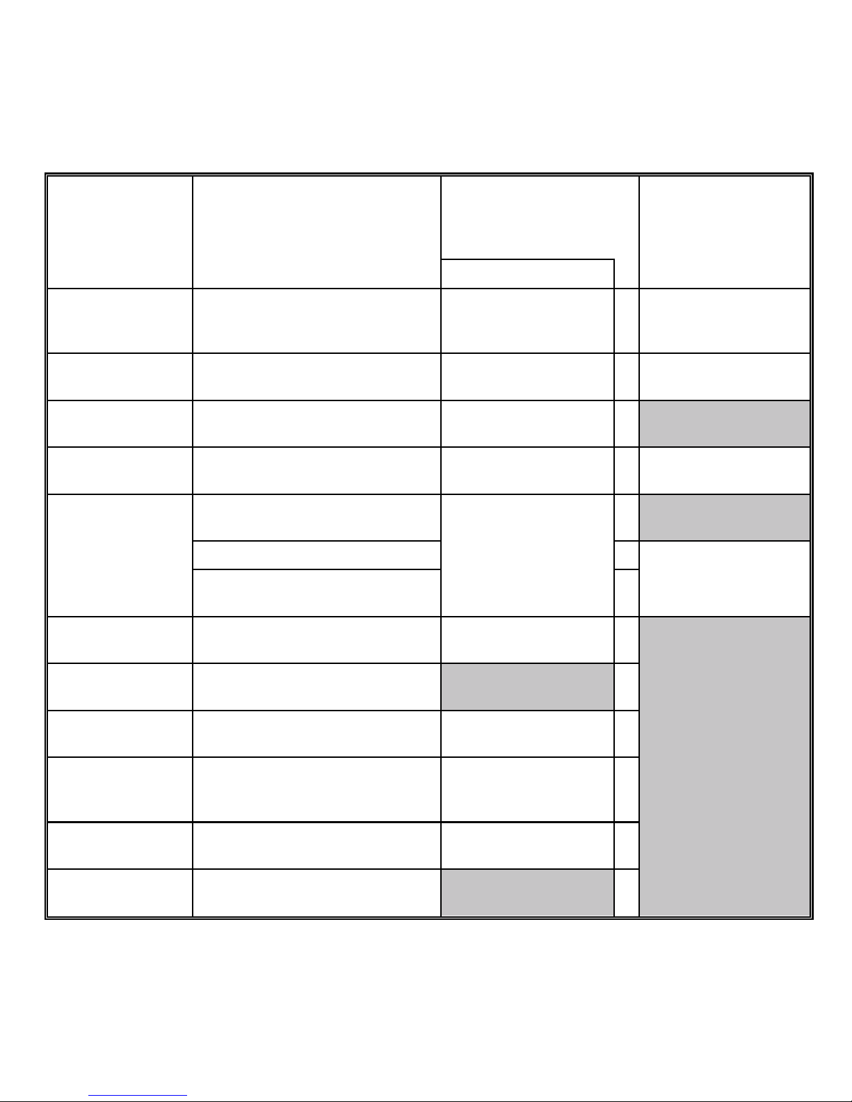
ÎFIGURE 1
(MSSMA424AE)
ÎMain Bearing Housing
Maintenance Points
ÎFIGURE 2
(MSSMA424AE)
ÎWater Seal Grease Point
ÎFIGURE 3
(MSSMA424AE)
ÎWater Seal Grease Relief
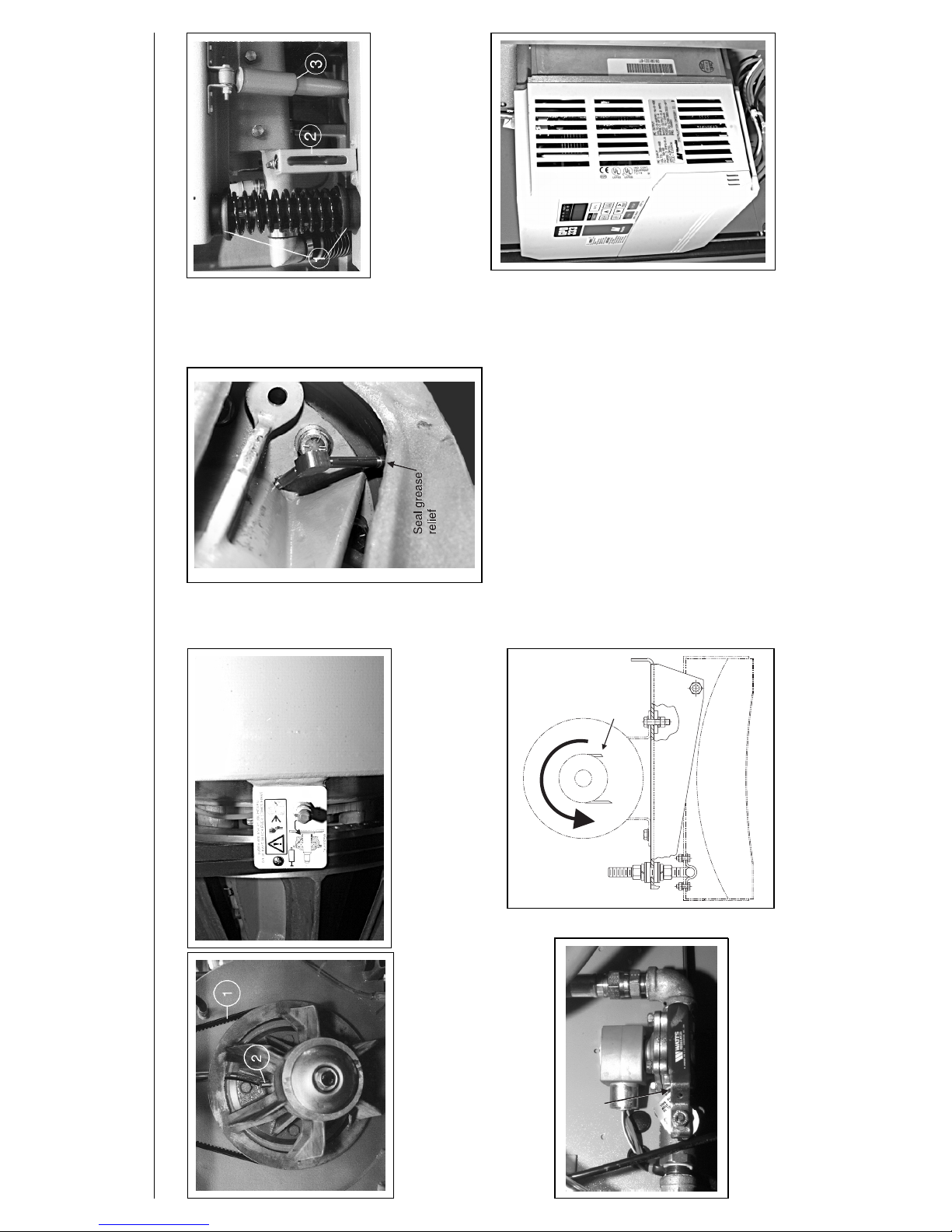
ÎFIGURE 4
(MSSMA424AE)
ÎIsolator and Shock
Maintenance Points
Cooldown
vernier
adjustment
Cooldown
vernier
adjustment
ÎFIGURE 5
(MSSMA424AE)
ÎCooldown Vernier Valve
Turn off power before servicing
Direction of rotation (Extract and Drain)
Rear of machine
Drive belt
ÎFIGURE 6
(MSSMA424AE)
ÎRotation Direction
ÎFIGURE 7
(MSSMA424AE)
ÎInverter
PREVENTIVE MAINTENANCE FOR THE
30022 SUSPENDED WASHER-EXTRACTOR MSSMA424AE/9852AV (2 of 3)
ÊTesting Belt Tension
NOTE: Do not refer to instruction sheet provided with tension testing tool. Use the “Initial tension”
column when adjusting belts that have never been used. Us e the “Final tension” column when adjusting belts
that have been used.
Check belt tension (see FIGURE 8) when replacing and
adjusting drive train components. A belt tension testing tool
(Milnor®part number 30T001), straight edge, and Belt Tension Specification table is required when setting belt tension.
Check tension for new belts according to the following
schedule.
•After 24 hours operation (three eight-hour shifts)
•After 80 hours operation (ten eight-hour shifts)
• After 160 hours operation (twenty eight-hour shifts)
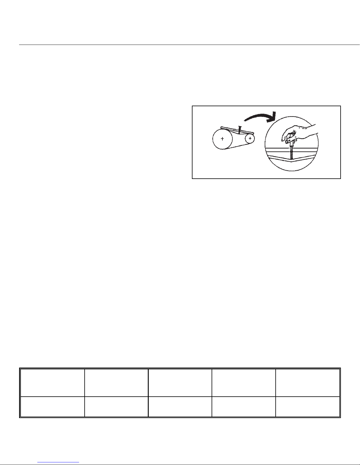
Set belt tension as follows:
1. Move upper O-ring on tension testing tool to uppermost position (resting against bottom edge of sliding cap).
2. Determine belt deflection for the tested belt (see FIGURE 1, Item 1 for the belt location, and Table below for
the setting). Move lower O-ring to the correct setting (inches or centimeters) on scale. Read the bottom edge
of the O-ring.
3. Place a straight edge along the top edge (pulley to pulley) of the belt to be tested. Depress the tension testing
tool by sliding the cap against the middle of the belt span until the bottom edge of the lower O-ring aligns
with the straight edge as shown in FIGURE 8.
4. Read the top of the upper O-ring position and determine if it is within specified range.
• See specifications in the “Initial tension” column for belts that have never been used.
• See specifications in the “Final tension” column for belts that have been used.
5. If reading is below specified range, belt must be tightened. If reading is above specified range, belt must be
loosened. Adjust belt and repeat Steps 1 through 4 until tension is within specified range.
ÏBelt Tension Specification
Belt
Belt deflection
inches
(millimeters)
Hertz
Initial tension
pounds
(kilograms)
Final tension
pounds
(kilograms)
Drive 24/64 (9.5) All 6.7 - 9.8
(3.0 - 4.4)
5.2 - 7.6
(2.4 - 3.4)
ÎFIGURE 8
(MSSMA424AE)
ÎTesting Belt Tension

ËAbout Belts
—All V-belts are not alike. So called “Super” or “High Capacity” belts frequently have considerably higher capacities than “Standard” belts. Sometimes a particular manufacturer’s V-belt will be more suitable for
a certain application, and another manufacturer’s V-belt may be suit able for a different appl ication. This m ay occur
in spite of the fact that both manufacturer’s V-belts are reputedly “interchangeabl e”. Because of this, it is al ways
best to purchase replacement belts from the original manufacturer of the equipment. If you do not wish to do this,
we suggest that when you replace the belts, you purchase the exact style and type belt s with whi ch the machine was
originally equipped. This is the best way to achieve belt life on your replacement belts equal to t he life of the original
set. (If you are not satisfied with the life of the original set, you should ask our factory if a better belt has been
developed for the specific application).
ÊBleach Note
Dry bleaches may cause the inside of the supply injector to show evidence of mild rusting. If this condition
occurs, be certain to carefully clean away the rusting at least once a week. Always inject dry bleach from the cup or
scoop. Never allow the dry bleach to come in direct contact with the stainless steel components of the supply
injector.
MSSM0261BE/9933AV
ÈREPLACING 30Fxx MAIN BEARINGS
ELECTROCUTION HAZARD—High voltage is present inside electrical boxes,
motors, and many other components, even when Master switch is
off
and/or any
emergency stop is
off.
You can be killed or seriously injured on contact with
high voltage.
☞ Lock OFF and tag out power at the wall disconnect before servicing.
☞ Maintenance must be performed only by qualified, authorized service personnel.
NOTE: A cylinder puller kit (P/N PK33-008) is available from Milnor® on a rental basis.
Maintenance procedures require:
• The proper cylinder puller
• The specified lubricant
• Loctite 271, anti-seize, Loctite silicone sealant, Loctite PST stainless steel pipe sealant and Permatex 2
adhesive (or their equivalents).
Oil or water dripping from the leak-off, or water in the bearing oil indicates leaking seals. Metal particles in
the bearing oil indicates damaged bearings. Ordinarily, only the shell front and cylinder need to be removed to
replace seals and bearings.
ÊRemoving the Shell Front and Cylinder
1. Remove the door interlock housing cover. Mark the terminal position of the wires and remove the wires from
the interlock switch. Loosen the two conduit connections and move the conduit so the shell front can be removed.
2. Remove all shell front attachments including pipes, hoses, and optional equipment. Drain the oil from the
bearing housing and inspect.
3. Remove the shell mount ring clip guard located on the top of the shell clamp ring, then mark the position of
the shell front with respect to the shell.
4. Support the shell front and remove the bolts, shell clamp ring, rubber extrusion, and shell front.
5. Remove the shaft retainer bolt, cover, spacer, and the two screws covering the puller mounting holes.
Mount puller and remove the cylinder.
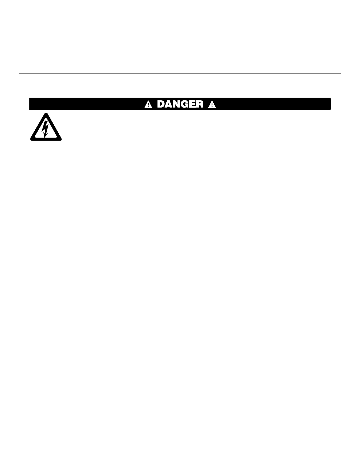
ÊReplacing Seals, Bearings, and Bearing Housing
NOTE: See FIGURE 1 during the following
procedures.
ËReplacing Seals
—If no water or metal particles are present in drained oil, replace seals and
O-rings as follows. If bearing oil contains water
or metal particles, see “Replacing Bearings” in
this section.
1. Remove the front shaft seal holder.
2. Inspect the shaft seal sleeve for nicks, gouges,
or excessive wear. If replacement is necessary, heat and tap the damaged sleeve off of
the shaft. Before installing the new sleeve,
ensure shaft and sleeve are clean and free
from oil. Apply Loctite 271 to the inside of
the sleeve, then tap sleeve on the shaft, and
remove excess Loctite.
3. Replace the seals and O-rings. Ensure that the new seals are
parallel within the shaft seal holder.
ËReinstalling the Seal Holder
Rear
seal/bearing
holder
Shims
Bearings
Seals
Front shaft
seal holder
Shaft
seal
sleeve
ÎFIGURE 1
(MSSM0261BE)
ÎBearing Housing Components
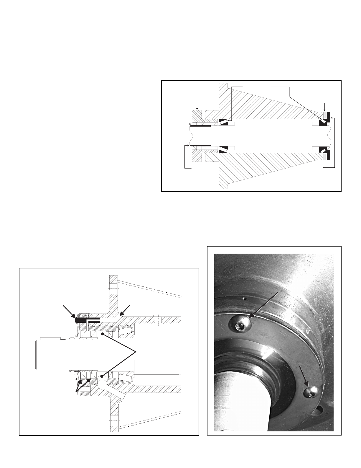
3/8" Socket
cap bolt
Grease
inlet
Water seals
Leak off
cavity
ÎFIGURE 2
(MSSM0261BE)
ÎSeal Holder Details
5/16" socket
cap bolt
(used in two
locations)
5/16" socket
cap bolt
(used in two
locations)
3/8" socket
cap bolt
(used in two
locations)
3/8" socket
cap bolt
(used in two
locations)
ÎFIGURE 3
(MSSM0261BE)
ÎInstalled Socket Cap Bolts
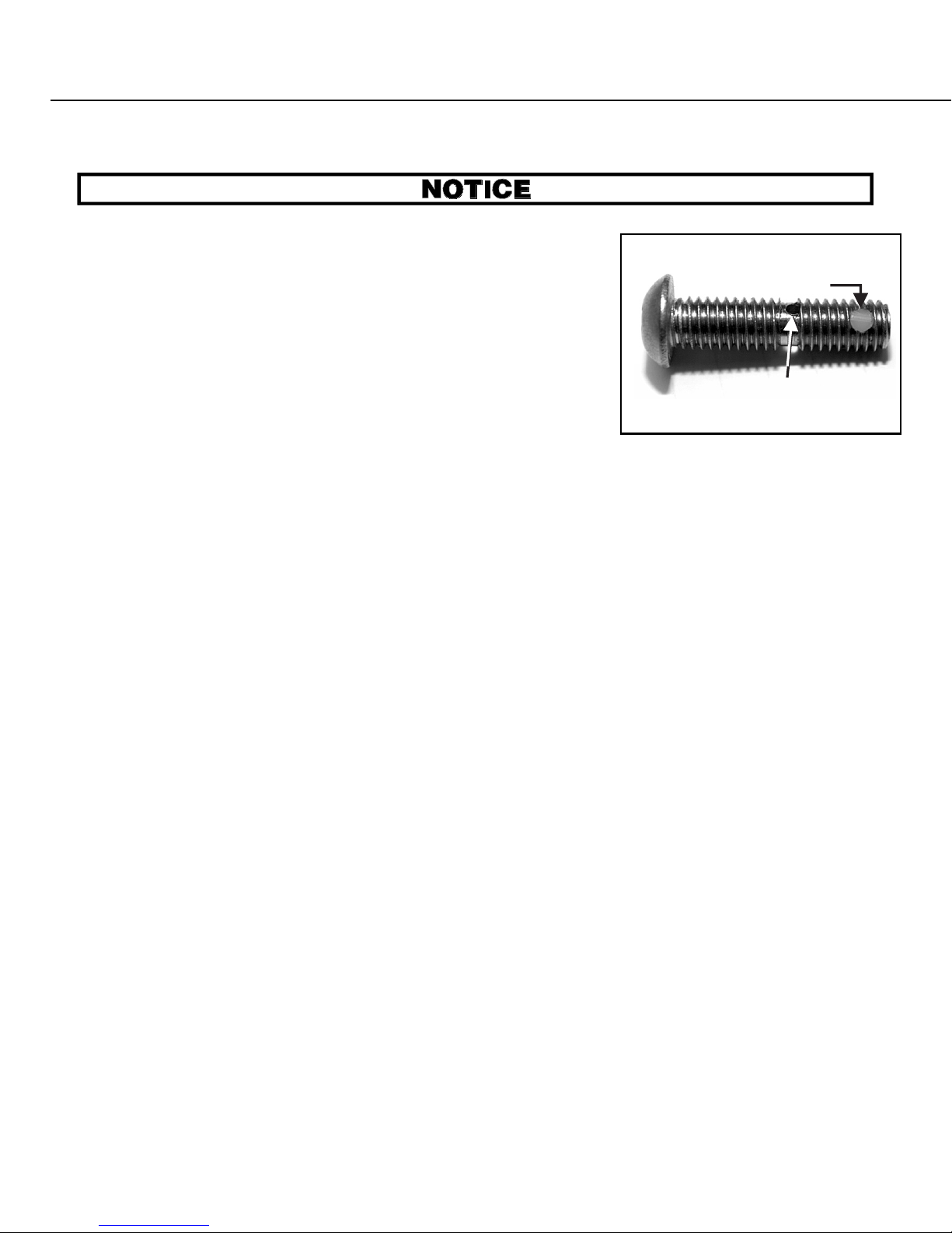
Bolts can break off and the seal holder can leak or loosen.
☞ Follow seal holder installation instructions carefull y.
☞ Do not over tighten bolts.
NOTE: The two 3/8" socket cap bolts are drilled to facilitate greasing
the water seals (see BMP980022, FIGURE 2, and FIGURE 4).
Initally, grade 8 hex head bolts are used to seat the seal holder, clamping it in place. After these bolts are torqued to specifications, the hex head
bolts are replaced one at a time with socket cap bolts (FIGURE 2 and 3). Use
anti-seize instead of threadlocker on the socket cap bolts during installation,
since these bolts use a nylon insert as a threadlocker.
1. Reinstall seal holder using hex head 3/8" and 5/16" bolts. Torque bolts
to the torque values provided in MSSM0101AE.
2. Remove one of the 5/16" hex head bolts. Using anti-seize, install a new 5/16" socket cap bolt, then tighten to
80 inch-pounds. Do not use the torque values listed in MSSM0101AE. Remove other 5/16" bolt and
repeat the step.
3. Remove one of the 3/8" hex head bolts. Using anti-seize, install a new 3/8" socket cap bolt. Tighten this bolt
to 150 inch-pounds (16.9 Newton meters). Remove other 3/8" bolt and repeat procedure.
Ë
ËReplacing Bearings
NOTE: Set bearing clearance only if major components of the original bearing housing (front shaft seal
holder, rear seal/bearing holder, shaft, or shims) are replaced. See “Setting Bearing Clearances” in this section after replacing major components.
The bearing housing does not need to be removed to change the bearings. Remove the bearing housing only
if insufficient room exists for the following procedures, or if the bearing housing (or a major housing component)
must be replaced.
1. Remove the front shaft seal holder and rear seal/bearing holder (containing the rear bearing). Note the posi-
tion and number of the shims between the rear seal/bearing holder and bearing housing. The shims must be
installed exactly as removed.
2. Remove the shaft, bearing cup, and bearing through the front of the bearing housing. Remove and discard
used bearings, cups, seals, and O-rings.
3. Install a new seal, bearing, and cup in the rear seal/bearing holder. Install the shims and the rear seal/bearing
holder.
4. Press a new front bearing on the shaft, then guide shaft into the rear seal/bearing holder. Do not scrape the
new bearings against the inside of the bearing housing.
Nylon insert
Drilled to allow greasing
of water seals
ÎFIGURE 4
(MSSM0261BE)
ÎDetails of 3/8"
Socket Cap Bolts
5. Center the shaft within the housing, then gently tap in the front bearing cup. Install the front shaft seal holder.
6. The shaft should turn in the housing.
ËSetting Bearing Clearances
NOTE: This procedure is required only if a major bearing housing component is replaced. See “Replacing
Bearings” in this section.
1. Set the clearance by removing all shims from the rear seal/bearing holder. Install the rear seal/bearing holder.
Leave a small gap between the bearing housing and rear seal/bearing holder.
2. Insert a lead wire in the gap between flanges. Tighten
each bolt slowly while turning the shaft. Stop tightening when the shaft just begins to drag or bind. Remove
the rear seal/bearing holder, being careful not to mark
or damage the lead wire.
3. Using a micrometer, measure the thickness of the lead
wire.
4. Add shims to the thickness of the lead wire to obtain a to-
tal thickness of 0.004" - 0.005" (0.102 - 0.127 millimeters). Install the rear seal/bearing holder using this
amount of shims.
5. The shaft should turn in the housing.
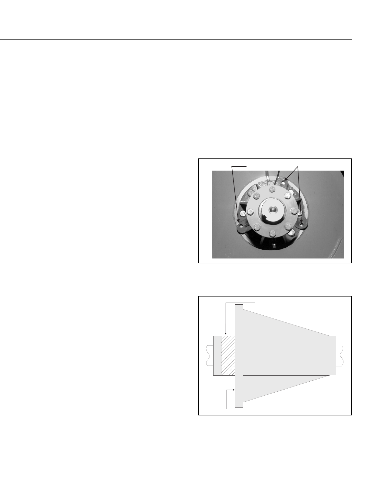
ËRemoving the Old Bearing Housing
Remove all fittings and connections from the bearing
housing. Tighten three 1/2 - 20 x 2 inch (50) long bolts
evenly into the push-off holes to separate the bearing housing from the shell.
ËInstalling the New Bearing Housing
NOTE: Use new bolts when reassembling the machine.
After determining that the shell is clean and free from
old adhesives and sealants, install the bearing housing, using
Loctite 271 and Loctite silicone sealant on bearing housing
mounting surface (as shown in FIGURE 6). Remove any excess compounds from machine. Install all of the original lubrication fittings and connections.
Push-off holes
ÎFIGURE 5
(MSSM0261BE)
ÎPush-off Holes
(Pulley Removed for Clarity)
Apply locking adhesive
to surface
Apply silicone
sealant to entire surface
ÎFIGURE 6
(MSSM0261BE)
ÎBearing Housing Installation
 Loading...