

Milnor 30015, 30020, 30022 Service Manual

Published Manual Number/ECN: MAP30RM1AE/99033N
• Publishing System: TPAS
• Access date: 05/11/2000
• Document ECN's: Latest Available
Service—
30015/30020/30022
Washer-Extractors
PELLERIN MILNOR CORPORATION POST OFFICE BOX 400, KENNER, LOUISIANA 70063-0400, U.S.A.

Please Read
About the Manual Identifying Information on the Cover
The front cover displays pertinent identifying information for this manual. Most important, are
the published manual number (part number) /ECN (date code). Generally, when a replacement
manual is furnished, it will have the same published manual number, but the latest available
ECN. This provides the user with the latest information applicable to his machine. Similarly all
documents comprising the manual will be the latest available as of the date the manual was
printed, even though older ECN dates for those documents may be listed in the table of
contents.
When communicating with the Milnor factory regarding this manual, please also provide the
other identifying information shown on the cover, including the publishing system, access date,
and whether the document ECN’s are the latest available or exact.
References to Yellow Troubleshooting Pages
This manual may contain references to “yellow pages.” Although the pages containing
troubleshooting procedures are no longer printed on yellow paper, troubleshooting instructions, if
any, will be contained in the easily located “Troubleshooting” chapter or section. See the table of
contents.
Trademarks of Pellerin Milnor Corporation
The following, some of which may be used in this manual, are trademarks of Pellerin Milnor
Corporation:
Ampsaver
Autolint
Auto-Purge
®
®
®
Autovac E-P Plus
®
CBW
Dye-Extractor® Hands-Off
Dyextractor® Hydro-Cushion
®
Gear Guardian
Mildata
®
®
®
®
®
Milnet
Milnor
®
Staph-Guard
System 4
Miltrac System 7
Miltron Totaltrol
®
®
®
®
Comments and Suggestions
Help us to improve this manual by sending your comments to:
Pellerin Milnor Corporation
Attn: Technical Publications
P. O. Box 400
Kenner, LA 70063-0400
Fax: (504) 469-1849

Table of Contents
for MAP30RM1AE/99033N
30015/30020/30022 Washer-Extractors
Page Description Document/ECN
1 About This Manual MHP30RM1AE/9541AV
3 Warranty BMP720097/92732A
5 How to Order Parts BMP720097R/72332A
6 Rigid Mount Washer-Extractor Installation & Service Safety MSIN0704AE/9271BV
9 Glossary of Tag Illustrations - M-Style Washer-Extractors MSIUUMTGAE/9449CV
13 Section 1: Service and Maintenance
14 Preventive Maintenance MSSM0705CE/9903AV
17 Fastener Torque Requirements MSSM0101CE/9906AV
36 Description of Single Motor Drive Train MSFD0703AE/9328AV
37 Description of Dual Motor Drive Train MSFD0701BE/9273BV
40 Drive Train Service for all 30015 and 30022 Rigid
Mount Washer-Extractors MSSM0706BE/9273DV
45 Section 2: Drive Assemblies
46 2 Groove Pulleys - Drive Chart (30015 & 30022
S4A, S4G, S4J, S4T) BMP930015/98383V
47 3 Groove Pulleys - Drive Chart (30015 & 30022
S4A, S4G, S4J, S4T) BMP970086/98383V
48 Drive Chart - Rigid Mount Washer-Extractors
(30015M4J, M4G, M4T, M6J, M6G & 30022M5J,
M5G, M5T) BMP910031/98373V
51 Motor Mount Assembly - 30015, 30020 & 30022
Rigid Mount Washer-Extractors BMP920027/93251V
53 Motor Mount - 30015 & 30020 S4A, S4G, S4J, S4T BMP950003/95107V
55 Replacing Main Bearings and Seals on 30015,
30020, 30022Cxx, Kxx, Sxx, and Mxx Models MSSM0708BE/9846AV
63 Section 3: Bearing Assemblies
64 Cylinder + Shell + Bearing + Console Installation
- 30015, 30020 & 30022 Rigid Mount Washer-
Extractors BMP910037/93251V
66 Main Bearing Assembly - 30015C4x, M4x, K5x, S5x BMP910032/96141V
68 Main Bearing Assembly BMP910033/96141V
70 Main Bearing Assembly - 30015M6x BMP910034/95116V
72 Jackshaft Bearing Replacement MSSM0709BE/9273BV
74 Jackshaft Assembly - 30015, 30020, 30022 Rigid
Mount Washer-Extractor BMP910035/93251V
77 Section 4: Shell and Door Assemblies
78 Shellfront Assembly, Conduit & Interlock Installation
- 30015, 30020, & 30022 Rigid Mount Washer-
Extractors BMP920024/93251V

Table of Contents, cont.
Page Description Document/ECN
80 Door Assembly - 30015 & 30020 Rigid Mount
Washer-Extractors BMP920009/94491V
82 Interlock Assembly BMP750046/97341V
85 Section 5: Control and Sensing Devices
86 Replacing and Adjusting the Power Supply MSSM0711AE/9272BV
90 Switch Panel Assembly - 30015, 30020 & 30022
MxG, MxJ, Cxx, K5x BMP880028/96143V
92 About the Coin Counter MSFD0501BE/9273AV
94 Coin Assembly Installation (240V) - 30015, 30020
& 30022 Coin Machines BMP920010/97281V
96 Vibration Safety Switch Adjust MSSMA408BE/9273BV
98 Vibration Safety Switch BMP910038/92343V
99 Section 6: Chemical Supply Devices
100 Liquid Supply Inlet Sidemount BMP940077/94286V
102 Supply Injector and Installation - 30015, 30020,
& 30022 Rigid Mount Washer-Extractors BMP920019/93251V
104 3 Compartment Supply Injector - 30015, 30020,
& 30022 Rigid Mount Washer Extractors BMP770149/96113V
106 Soap Chute & Installation - 30015, 30020, &
30022 Rigid Mount Washer-Extractors BMP920013/93251V
107 Section 7: Water and Steam Piping and
Assemblies
108 Schematic Symbols Key BMP920008/93027V
109 Water/Steam/Drain Schematics - 30015, 30020,
& 30022 Rigid Mount Washer-Extractors BMP920015/96132V
111 Water Inlet & Level Switch Installation & Mounting
Hardware - 30015, 30020, & 30022 Rigid Mount
Washer-Extractors BMP920016/93251V
113 Hays Electric Inlet Valves BMP700710/96081V
115 2-Way Electric Water Valve BMP920029/98443V
117 Universal Actuators & Mounting Hardware for
Watts Ball Valves - New Pivot BMP920005/96067V
120 Air Cylinder for 2" Watts Ball Valves BMP920006/2000133V
122 Watts Ball Valves and Repair Kits BMP920007/96066V
124 Paddlewheel Flow Sensor BMP920025/92662V
126 Steam Installation - 30015, 30020, & 30022 Rigid
Mount Washer-Extractors BMP920021/93251V
128 1/2" & 3/4" Hayes Steam Valves BMP920028/92776V
129 Drain Sump Installation - 30015, 30020, & 30022
Rigid Mount Washer-Extractors BMP920014/93251V
130 Drain Valve Installation - 30015, 30020 & 30022
Rigid Mount Washer-Extractors BMP920020/93251V
132 Electric Drain Valve - 30022 Rigid Mount Washer-
Extractors BMP920017/93251V

Table of Contents, cont.
Page Description Document/ECN
133 Section 8: Pneumatic Piping and Assemblies
134 Pneumatic Schematic - 30015, 30020 & 30022
Rigid Mount Washer-Extractors BMP920018/93251V
135 3 Way Pilot Valves BMP900032/91182V


ABOUT THIS MANUAL
MHP30RM1AE/9541AV (1 of 1)
Scope
—This instruction manual is intended to provide preventive maintenance procedures, service procedures, and mechanical parts identification for all Milnor® 30015, 30020, and 30022 model rigid mount
washer-extractors. Measurements are in commonly used US and metric units unless otherwise noted.
See the appropriate programming, operating, and troubleshooting manual for inform ation on the control
system. See the schematic manual for electrical parts identification and electrical troubleshooting.
Manual Number/Date Code (When To Discard or Save)
—The manual number/date code
is located on the inside front cover, upper right corner just above the manual name. Whenever the manual is
reprinted with new information, part of this number changes. If the date code after the “/” changes , the new
version applies to all machines covered by the old version, but is improved— thus the old version can
be discarded. If the manual number before the “/” changes, the new manual covers only new machines.
Example: Discard MATMODELAE/8739CV when MATMODELAE/8739DV is received (minor improvements). Also, discard MATMODELAE/87
V when MATMODELAE/87
39D
V is received (major im-
46A
provements). But keep MATMODELAE/8746FV when MATMODELBE/8815AV is received, since the
new manual no longer applies to machines originally shipped with the old manual.
Documents and Change Bars
—The individual documents comprising this manual use the same
revision criteria as the manual. Text documents also display change bars. Example: When section
MSOP0599AE/9135BV becomes MSOP0599AE/9135CV, change bars with the letter “C” appear next to all
changes for this revision. For a major rewrite (e.g., MSOP0599AE/92
For Assistance
—Please call:
V), all change bars are deleted.
26A
Trademarks of Pellerin Milnor Corporation
this publication, are trademarks of Pellerin Milnor Corporation:
Ampsaver
Autolint
Auto-Purge
®
®
®
Autovac
®
CBW
Dye-Extractor
Dyextractor
E-P Plus
—The following, some of which may be used in
®
®
®
Hands-Off
Hydro-Cushion
Mildata
®
Gear Guardian
®
®
®
Milnet
Milnor
Miltrac
Miltron
®
®
Staph-Guard
System 4
System 7
Totaltrol
®
®
®
®


3(//(5,10,/125&25325$7,21
/,0,7('67$1'$5':$55$17<
We warrant to the original purchaser that MILNOR machines including electronic
hardware/software (hereafter referred to as “equipment”), will be free from defects in material
and workmanship for a period of one year from the date of shipment from our factory with no
operating hour limitation. This warranty is contingent upon the equipment being installed,
operated and serviced as specified in the operating manual supplied with the equipment, and
operated under normal conditions by competent operators.
Providing we receive written notification of a warranted defect within 30 days of its discovery,
we will – at our option – repair or replace the defective part or parts, FOB our factory. We
retain the right to require inspection of the parts claimed defective in our factory prior to
repairing or replacing same. We will not be responsible, or in any way liable, for unauthorized
repairs or service to our equipment, and this warranty shall be void if the equipment is repaired
or altered in any way without MILNOR’s written consent.
Parts which require routine replacement due to normal wear – such as gaskets, contact points,
brake and clutch linings and similar parts – are not covered by this warranty, nor are parts
damaged by exposure to weather or to chemicals.
We reserve the right to make changes in the design and/or construction of our equipment
(including purchased components) without obligation to change any equipment previously
supplied.
ANY SALE OR FURNISHING OF ANY EQUIPMENT BY MILNOR IS MADE ONLY UPON
THE EXPRESS UNDERSTANDING THAT MILNOR MAKES NO EXPRESSED OR IMPLIED
WARRANTIES OF MERCHANTABILITY OR FITNESS FOR ANY PARTICULAR USE OR
PURPOSE. MILNOR WILL NOT BE RESPONSIBLE FOR ANY COSTS OR DAMAGES
ACTUALLY INCURRED OR REQUIRED AS A RESULT OF: THE FAILURE OF ANY OTHER
PERSON OR ENTITY TO PERFORM ITS RESPONSIBILITIES, FIRE OR OTHER HAZARD,
ACCIDENT, IMPROPER STORAGE, MISUSE, NEGLECT, POWER OR ENVIRONMENTAL
CONTROL MALFUNCTIONS, DAMAGE FROM LIQUIDS, OR ANY OTHER CAUSE BEYOND
THE NORMAL RANGE OF USE. REGARDLESS OF HOW CAUSED, IN NO EVENT SHALL
MILNOR BE LIABLE FOR SPECIAL, INDIRECT, PUNITIVE, LIQUIDATED, OR
CONSEQUENTIAL COSTS OR DAMAGES, OR ANY COSTS OR DAMAGES WHATSOEVER
WHICH EXCEED THE PRICE PAID TO MILNOR FOR THE EQUIPMENT IT SELLS OR
FURNISHES.
WE NEITHER ASSUME, NOR AUTHORIZE ANY EMPLOYEE OR OTHER PERSON TO
ASSUME FOR US, ANY OTHER RESPONSIBILITY AND/OR LIABILITY IN CONNECTION
WITH THE SALE OR FURNISHING OF OUR EQUIPMENT TO ANY BUYER.
BMP720097
92732A


How to order repair parts
Repair parts may be ordered either from the authorized dealer who sold you this
machine, or directly from the MILNOR factory. In most cases, your dealer will
have these parts in stock.
When ordering parts, please be sure to give us the followin g information:
1. Model and serial number of the machine for which the parts are required
2. Part number
3. Name of the part
4. Quantity needed
5. Method of shipment desired
6. In correspondence regarding motors or electrical controls, please include all
nameplate data, including wiring diagram number and the make or
manufacturer of the motor or controls.
All parts will be shipped C.O.D. transportation charges collect on ly.
Please read this manual
It is strongly recommended that you read the installation and operating manual
before attempting to install or operate your machine. We suggest that this manual
be kept in your business office so that it will not become lo st.
PELLERIN MILNOR CORPORATION
32%2;.(11(5/$ 86$
FAX: Administration 504/468-9307, Engineering 504/469-1849, Service 504/469-9777
BMP720097R
72332A

MSIN0704AE/9271BV
ÈRIGID MOUNT WASHER-EXTRACTOR
INSTALLATION AND SERVICE SAFETY
ÊGeneral Safety Requirements
(specific warnings, next page and throughout manual)
Incorrect installation, neglected preventive maintenance, abuse, and/or improper repairs or changes to the
machine can cause unsafe operation and personal injuries, such as multiple fractures, amputations, or death. The
owner or his selected representative ( owner/user) is responsibl e for understanding and ensuring the proper operation
and maintenance of the machine. The owner/user must familiarize himself with the contents of all machine instruction manuals. The owner/user should direct any questions about these instructions to a Milnor® dealer or the Milnor® Service department.
Most regulatory authorities (including OSHA in the USA) hold the owner/user ultimately responsible for
maintaining a safe working environment. Therefore, the owner/user must do the following:
• recognize all foreseeable safety hazards within his facility and take actions to protect his personnel,
equipment, and facility
• require that personnel are familiar with all functional and safety aspects of the machine
• ensure safety devices installed on the machine are in place and properly maintained
• ensure all machine parts and assemblies are properly maintained.
ËLaundry Facility
—Provide a supporting floor that is strong and rigid enough to support--with a reasonable
safety factor and without undue or objectionable deflection--the weight of the fully loaded machine and the forces
transmitted by it during operation. (For washer-extractors, see “ABOUT THE FORCES TRANSMITTED BY MILNOR® WASHER-EXTRACTORS.”) Provide sufficient clearance for machine movement. Provide any safety
guards, fences, restraints, devices, and verbal and/or posted restrictions necessary to prevent personnel, machines,
or other moving machinery from accessing the machine or its path. Provide adequate ventilation to carry away heat
and vapors. Ensure service connections to installed machines meet local and national safety standards, especially
regarding the electrical disconnect (see the National Electric C ode). Prominently pos t safety inform ation, including
signs showing the source of electrical disconnect.
ËPersonnel
—Inform personnel about hazard avoidance and the importance of care and common sense. Provide
personnel with the safety and operating instructions that apply to them. Verify that pers onnel use proper safety and
operating procedures. Verify that that personnel understand and abide by point-of-hazard tags on the machine and
procedure-specific precautions in the instruction manuals.
ËSafety Devices
—Ensure that no one eliminates or disables any s afety device on t he m achine or in t hs facilit y.
Do not allow machine to be used with any missing guard or cover. Service any failing or malfunctioning device
before operating the machine.
ËMaintenance
—Ensure the machine is inspected and serviced in accordance with the norms of good practice and
with the preventive maintenance schedule. Replace belts, pulleys, brake shoes/disks, clutch plates/tires, rollers,
seals, alignment guides, etc. before they are severely worn. Immediately investigate any evidence of impending
failure and make needed repairs (e.g., cylinder, shell, or frame cracks; drive components such as motors, gear boxes,
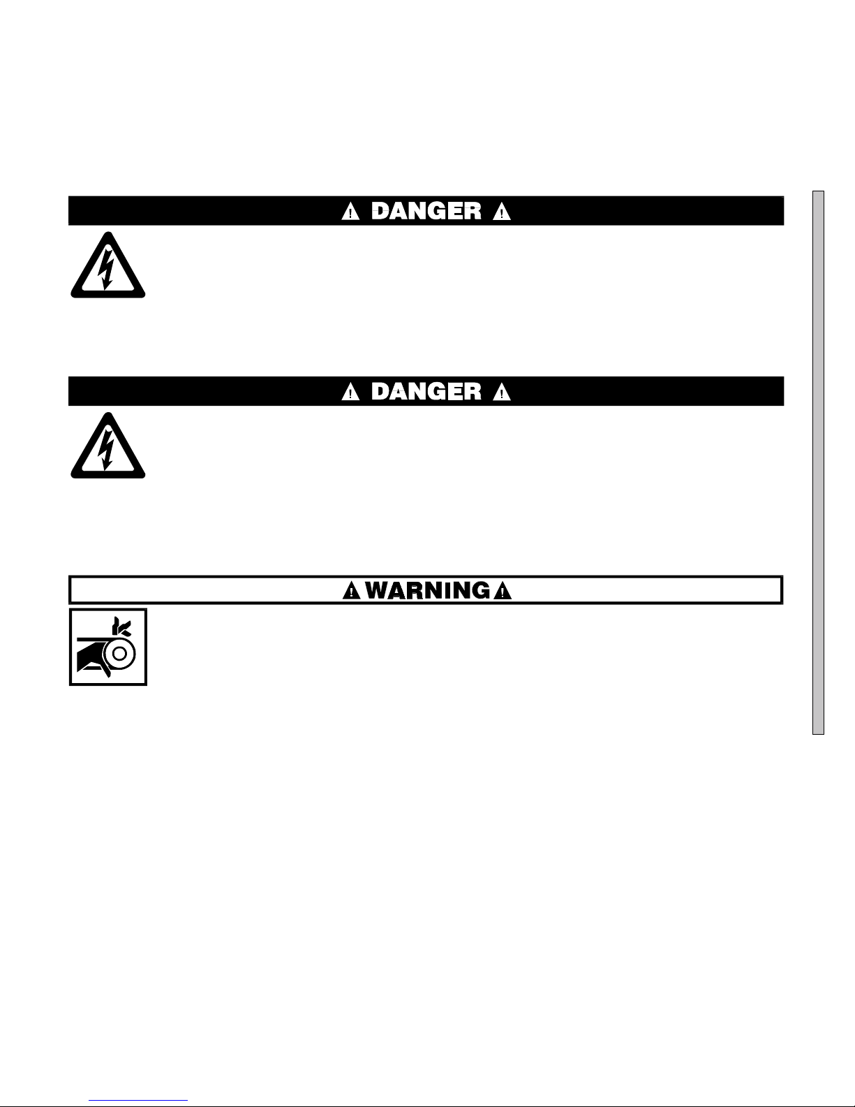
ÊHazards During Assembly
ELECTROCUTION HAZARD—Contact with high voltage can kill or seriously injure you.
☞ All electrical connections must be made by a competent electrician.
ÊHazards During Servicing and Maintenance
ELECTROCUTION HAZARD—High voltage is present inside electric boxes, motors and many other components. Power switches on machine control panels
disable only control circuit power in certain boxes. You can be killed or seriously injured on contact with high voltage.
☞ Lock OFF and tag out power at the wall disconnect before servicing, except
where specifically instructed otherwise in this manual.
ENTANGLE AND CRUSH HAZARD—Belts and pulleys can entangle and crush
body parts.
☞ Lock OFF and tag out power at the wall disconnect before servicing, except
where specifically instructed otherwise in this manual.
☞ Insure belt guards are in place during service procedures.
B

ÊHazards Requiring Immediate Service
MULTIPLE HAZARDS—Failure to maintain machine in proper working order can result in
fatal or serious injury to operators and/or damage to property. DO NOT permit operation
under any of the following circumstances:
☞ Malfunctioning door interlock mechanism.
☞ Malfunctioning limit switches.
☞ Malfunctioning two hand inching.
☞ Any evidence of cylinder damage.
☞ Missing or removed guards, covers, or side panels.
☞ Malfunctioning tilting components, including but not limited to safety limit switches,
electrical interlocks, and operator controls.
☞ If any of these conditions occur:
• The machine makes a sound like skidding automobile tires as it comes out of extract.
• The wash or drain clutch does not disengage or it reengages during extract.
• V-bel ts jum p off at the start of, during, or at the end of extract.
• A strange whining sound occurs at any time during extract.
B

7\_ccQbi_VDQW9\\ecdbQdY_^c±
=Cdi\UGQcXUb5hdbQSd_bc
Illustration Explanation Illustration Explanation
Stop! Read the manual first for complete
instructions before continuing.
Do not jack the machine here.
Do not lift the machine here.
<B8DD<C604(##(2E
Use three point or four point lifting as
determined by the lifting eyes furnished. Rig
the load using lifting cables of sufficient size
and length to ensure cables are not
over-stressed.
Do not lift the machine from one corner or one
side edge.
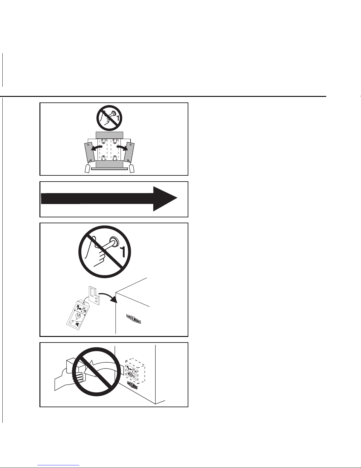
Do not start this machine until the packing
materials, lifting brackets, etc. with this tag
attached or behind this panel are removed.
These materials are painted red. Safety stands
or brackets (also painted red) may be provided
with this machine. Do not discard safety
stands or brackets
This motor or pump should rotate in the
direction of the arrow.
Do not start this machine until the part with
this tag is installed on the machine.
Do not remove this component from the
machine.
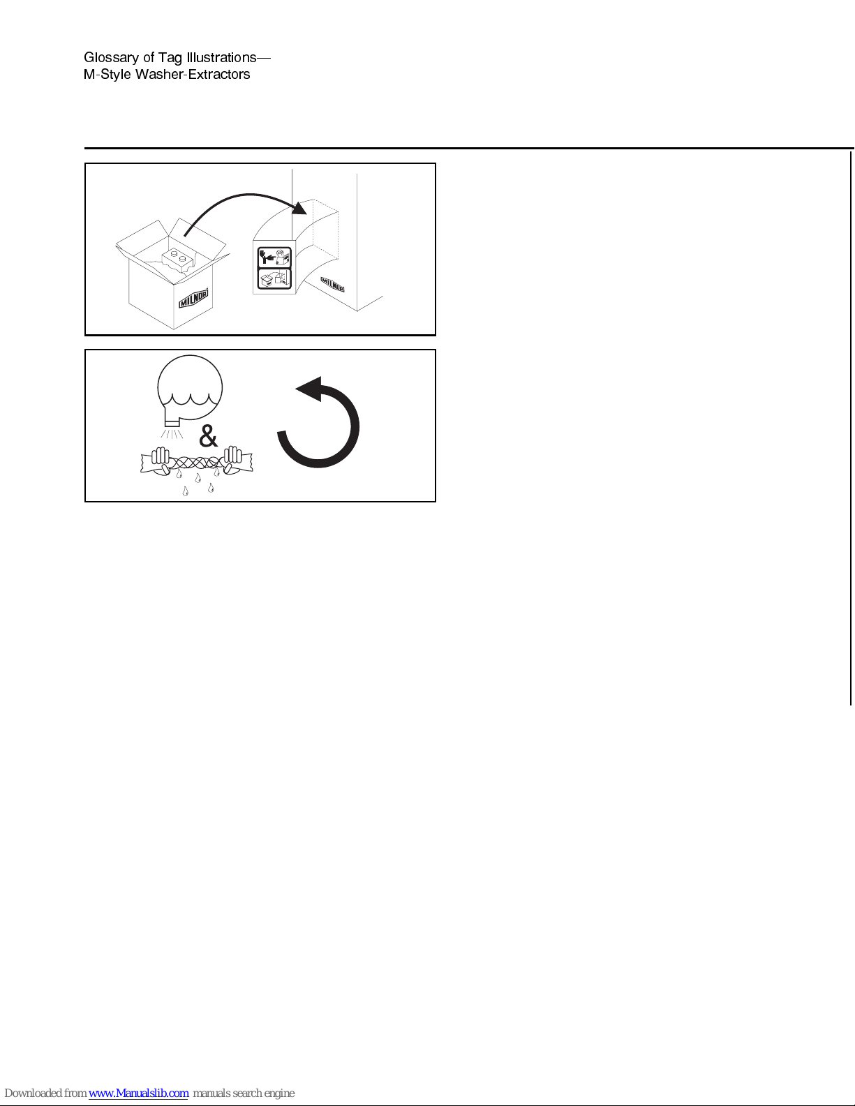
Illustration Explanation Illustration Explanation
Install the appropriate part here before
operating the machine.
During drain and extract, the cylinder must
rotate counterclockwise when viewed from
here.
7\_ccQbi _V DQW 9\\ecdbQdY_^c±
=Cdi\U GQcXUb5hdbQSd_bc =C9EE=D715)$$)3F " "
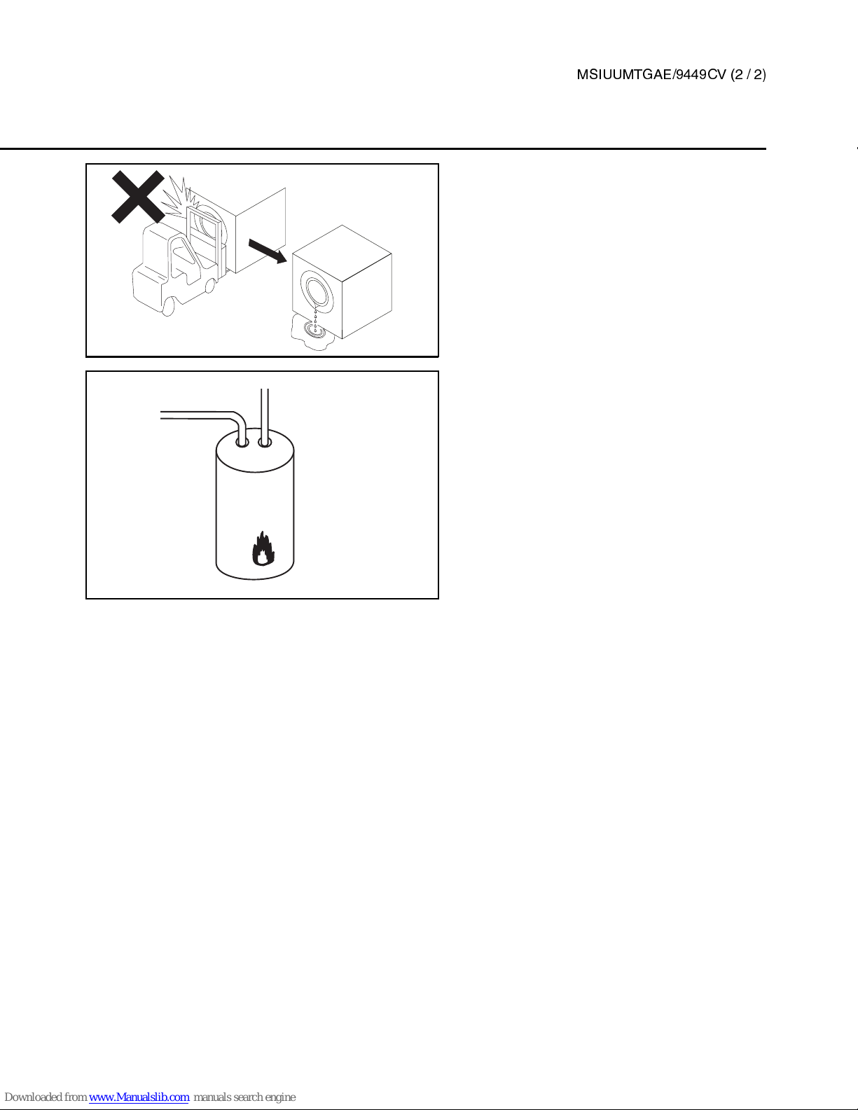
Do not strike shell front of washer-extractors
during fork lifting. Striking shell front will
cause door to leak.
This is the hot water inlet.

Section 1
Service and Maintenance
MSSM0705CE/9903AV
ÈPREVENTIVE MAINTENANCE
As required by the warranty, to ensure safe operation, and to achieve optimum performance and service life
from Milnor® washer-extractors, the schedules, instructions, and precautions herein must be strictly followed.
ÏPreventive Maintenance Schedule
Component Procedure Frequency Info. Source
Door interlock
(coin machines)
Test functioning for safe operation. daily MSOP0512AE in
Operating and
Troubleshooting
Manual
Electronic coin counter
(coin machines)
Test functioning for safe operation. monthly
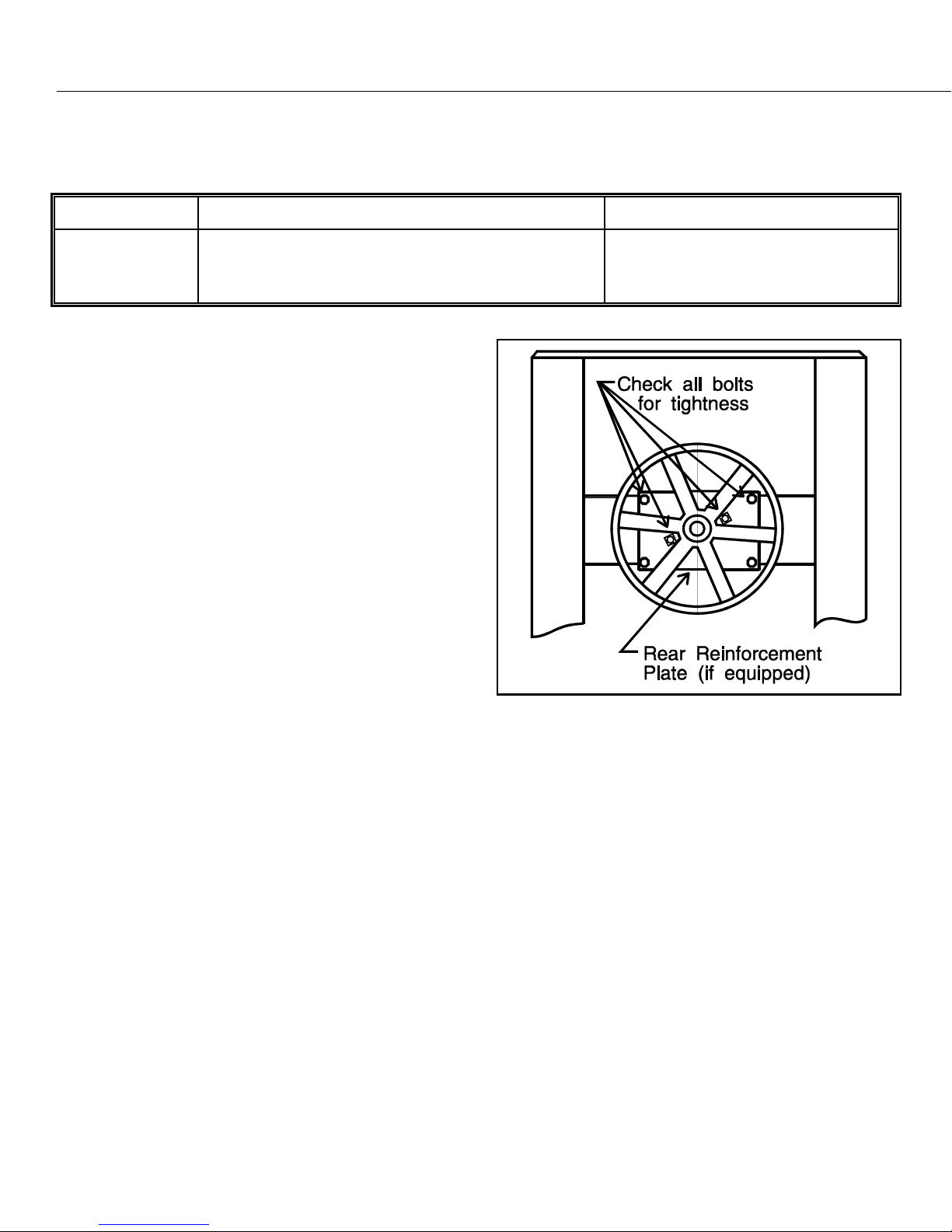
Main bearing housing Change lubricant. Check rear bolt
tightness and adjust if necessary.
every four months this section
(see FIGURE 1)
Foundation bolts Check bolt tightness and wear.
Adjust or replace if necessary. every four months
dimensional
drawing
(see NOTE 1 )
Drive train Check belt tension and wear. Check
pulleys and other drive components
for wear. Replace if necessary.
every four months
MSSM0706BE
(see NOTE 1 )
3/5 Compartment
Supply injector
(if so equipped)
Inspect and clean strainers in water
valves, and each compartment. If rust is
detected, carefully clean it away once
each week.
every four months
BMP770149
BMP920019
(see NOTE 2)
Steam strainer
(if so equipped)
Inspect and clean strainer. every four months BMP920015
(see NOTE 2)
NOTE 1: See Table of Contents for information not in this section.
NOTE 2: Drawings apply only to 30015Mxx, and Sxx; 30020Mxx; 30022Mxx, and Sxx models.
ÊMain Bearing Housing Preventive Maintenance
ELECTROCUTION HAZARD—High voltage is present inside electric boxes, motors, and many other components. Power switches on machine disable only
control circuit power in certain boxes. You can be killed or seriously injured on
contact with high voltage.
☞ Lock OFF and tag out power at the wall disconnect before servicing.
ENTANGLE AND CRUSH HAZARD—Belts and pulleys can entangle and crush
body parts.
☞ Lock OFF and tag out power at the wall disconnect before servicing, except
where specifically instructed otherwise in this section.
☞ Permit only qualified maintenance personnel to perform these procedures.
ËLubrication Procedures
—See the appropriate main bearing assembly drawing (if provi ded) during this
procedure (see Table of Contents).
1. Remove the console top by prying out the four plugs from each corner on the top of the machine and remov-
ing the four bolts. Remove the belt guard.
2. Remove the drain plug on the bottom of the main bearing housing and allow the bearing housing to drain
completely. Inspect the leak-off, drained oil, and magnetic drain plug for water and/or metal particles. Water
and/or metal particles can indicate worn or damaged seals and bearings. See “REPLACING MAIN BEARINGS AND SEALS,” if provided (see Table of Contents). Install the drain plug.
3. Locate the two 1/2" plastic tubes secured to the frame. Clean the surrounding area and remove the cork
stoppers from each.
MALFUNCTION HAZARD—Oil spilled on components may cause machine malfunction.
☞ Refill bearing housing carefully.
MACHINE DAMAGE HAZARD—Mixing incompatible lubricants will result in severe machine damage.
☞ DO NOT mix different base lubricants.
☞ Before using a non-specified lubricant, consult the lubricant manufacturer
to determine compatibility.
4. Strictly following lubrication specifications, refill the bearing housing. After refilling the bearing housing,
reinstall the cork stoppers and clean any excess lubricant from the machine.
ÏLubrication Specifications
Component Lubricant/Type Amount of Lubricant
Main bearing
housing
Any high quality SAE 30, 40, or 50 (ISO 100, 140,
or 220) single weight heavy duty motor oil,
non-detergent if available
22 ounces (623.7 grams)
ËBolt Inspection
Check the main bearing support bolts for tightnes s as
shown in FIGURE 1.
ÎFIGURE 1
(MSSM0705CE)
ÎMain Bearing Housing
Bolt Locations
MSSM0101CE/9 90 6A V (1of 19 )
ÈFASTENER TORQUE REQUIREMENTS
The specifications in this section apply to 1/4 inch and larger Unified National fine and coarse fasteners used on
Milnor® machines. This information is to be used only when torque specifications are not stated in the installation
or service instructions.
When tightening applicable fastener, abide by the follow-
ing precautions:
1. Always use new fasteners. Replace bolts, nuts, flat wash-
ers, and lock washers in the order shown on the parts
drawing.
2. Unless otherwise specified, use:
• Loctite® 271 threadlocker or equivalent for bearing
housing mounting bolts from one half to one inch in di-
ameter.
• Loctite® 277 threadlocker or equivalent for bearing
housing mounting bolts of one inch diameter or larger.
• Loctite® 242 threadlocker for all other fasteners
requiring thread locking compound.
3. Use a torque wrench to assure proper tightness.
4. Never lubricate fasteners. The values specified herein are
maximum recommended torques and are calculated from
published ASTM and SAE data. Actual allowable torques
are application dependent and can vary for many reasons,
(joint types, gaskets, etc.). Use these values as a guide.
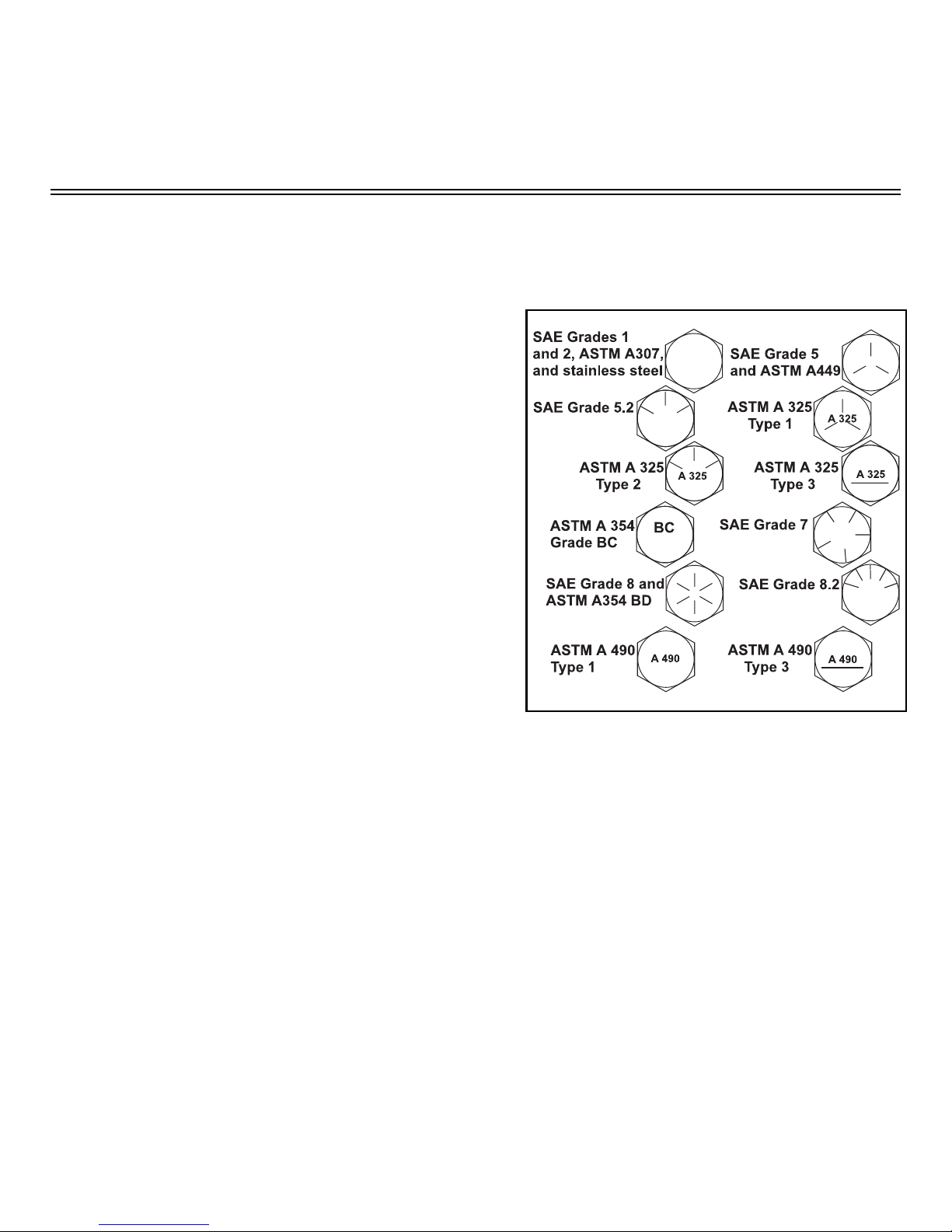
5. Although FIGURE 1 depicts hex head bolts, the table applies to all head types.
ÎFIGURE 1
ÎFastener Grade Markings
(MSSM0101CE)
ÊFasteners and Threadlocker
ËHow Fasteners Loosen
bly. With the fastener at the proper torque, 85% of the tightening torque is absorbed in the threads and under the
fastener head. The remaining 15% provides t he fricti on t hat prevents the t hread from sl ippi ng. When thi s frict ion is
overcome (by bending, thermal expansion, internal pressures, functional loads, or impact) the thread slips and loosens. Although higher torques reduce the likelihood of thread slippage, if slippage occurs, the threads unwind and
the fastener loosens. Once thread slippage begins, vibration increases the rate of loosening.
ËPreventing Loosening
cation of a threadlocking compound. Threadlocker provides lubrication during assembly, then hardens to seal the
threads against corrosion and provide resistance to thread slippage.
—Standard threaded fasteners are manufactured with a clearance fit for easy assem-
—The most effective way to prevent loosening of threaded parts is by proper appli-
MSSM0101CE/9906AV (2 of 19)
ÊApplying Threadlocker
NOTE: The following threadlocker information and
illustrations are excerpts from the Loctite® User’s
Guide and are used with permission.
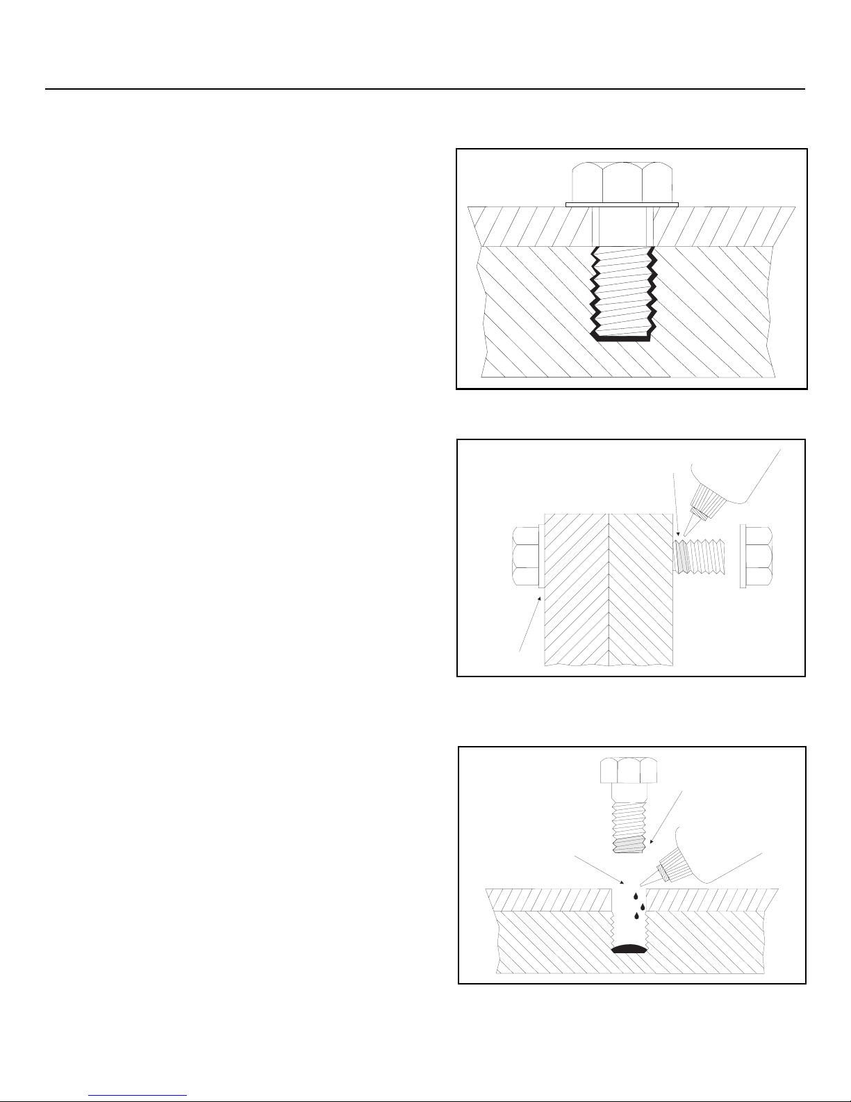
For maximum strength, threadlocker must fill the thread
voids completely, as shown in FIGURE 2. Organic or petroleum solvent will remove excess uncured adhesive from
joints. Consult information below for the specific fastener application.
ËBolts and Nuts
—See FIGURE 3.
1. Clean all threads (bolt and nut) with cleaning solvent.
2. Spray all threads with Loctite® Primer N. Allow to dry.
3. Insert bolt into through hole assembly.
4. Apply several drops of threadlocker onto bolt engage-
ment area.
5. Assemble and tighten nut to correct torque for the
threadlocker.
ËBlind Holes
—See FIGURE 4.
1. Clean all threads (bolt and nut) with cleaning solvent.
2. Spray all threads with Loctite® Primer N. Allow to dry.
3. Squirt several drops down female threads into bottom of
hole.
4. Apply several drops to bolt.
Not here
ÎFIGURE 2
(MSSM0101CE)
ÎCorrect Threadlocker Use
Apply here
ÎFIGURE 3
(MSSM0101CE)
ÎApplying Threadlocker to
Through Hole
Onto
threads
5. Tighten to correct torque for the threadlocker.
Onto
threads
ÎFIGURE 4
(MSSM0101CE)
ÎApplying Threadlocker to Blind Holes
FASTENER TORQUE REQUIREMENTS MSSM0101CE/9906AV (3 of 19)
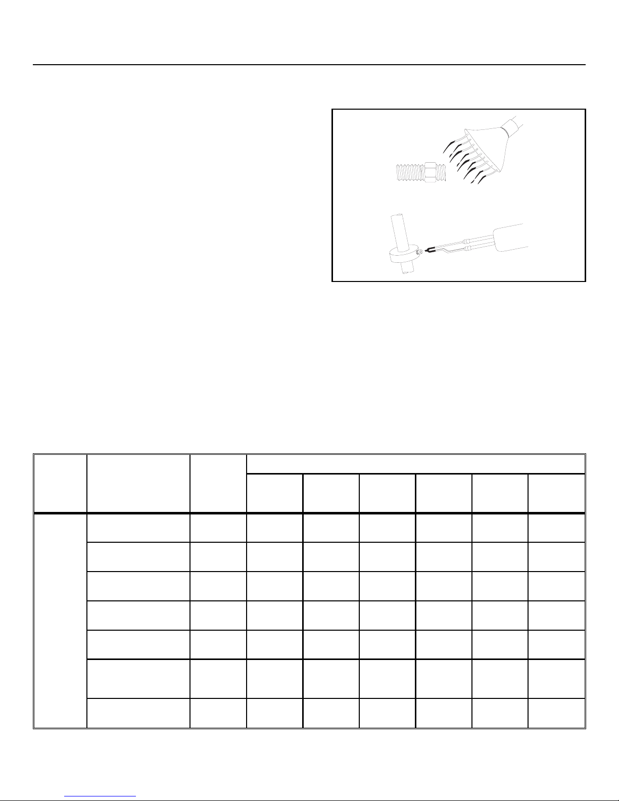
ËRemoving Fasteners
High strength threadlockers like Loctite® 271 (or equivalent)
may be weakened by heating to at least 500o F (260o C) as
follows.
1. Apply localized heat to fastener as shown in FIGURE 5.
2. Disassemble while hot. Once disassembled, the cured ad-
hesive can be removed with Loctite® Gasket Remover
#790 (or equivalent).
Nominal
bolt size
Grade
Designation and
Standard
1/4 - 20 SAE Grade 1
ASTM A307
SAE Grade 2 4.1
ÎRemoving High Strength Threadlocker
ÏCarbon Steel Fasteners
Ï
All values in foot pounds and (Newton meters)
Zinc or
Cadmium
Plated
2.5
(3.39)
(5.56)
If instructions call for :
Loctite
222 or
Loctite
242
262
3.0
(4.06)
4.9
(6.64)
3.3
(4.47)
5.5
(7.45)
Loctite
271
3.6
(4.88)
6.0
(8.13)
ÎFIGURE 5
Loctite
272
4.6
(6.23)
7.7
(10.44)
(MSSM0101CE)
Loctite
277
4.3
(5.83)
7.1
(9.63)
Bare
3.3
(4.47)
5.5
(7.46)
SAE Grade 4 4.8
(6.50)
SAE Grade 5
ASTM A449
(8.54)
SAE Grade 7 7.9
(10.7)
SAE Grade 8
ASTM A354 Grade
(12.0)
BD
ASTM A354 Grade
BC
(10.7)
6.3
8.9
7.9
5.8
(7.86)
7.6
(10.3)
9.4
(12.7)
10.7
(14.5)
9.4
(12.7)
6.4
(8.67)
8.4
(11.38)
10.5
(14.23)
11.9
(16.13)
10.5
(14.23)
7.0
(9.49)
9.3
(12.60)
11.5
(15.59)
13.1
(17.76)
11.5
(15.59)
9.0
(12.20)
11.8
(15.99)
14.7
(19.93)
16.6
(22.50)
14.7
(19.93)
8.3
(11.25)
11.0
(14.91)
13.6
(18.44)
15.4
(20.88)
13.6
(18.44)
6.4
(8.67)
8.4
(11.39)
10.5
(14.23)
11.9
(16.13)
10.5
(14.23)

MSSM0101CE/9906AV (4 of 19)
Ï
All values in foot pounds and (Newton meters)
Nominal bolt
Grade Designation
and Standard
size
1/4 - 28 SAE Grade 1
ASTM A307
SAE Grade 2 4.7
SAE Grade 4 5.5
SAE Grade 5
ASTM A449
SAE Grade 7 8.9
SAE Grade 8
ASTM A354 Grade
BD
ASTM A354 Grade
BC
Zinc or
If instructions call for :
Cadmium
Plated
Loctite
222 or
Loctite
242
Loctite
271
Loctite
272
Loctite
277
Bare
262
2.8
(3.80)
(6.37)
(7.46)
7.3
(9.90)
(12.07)
10.2
(13.83)
3.4
(4.61)
5.6
(7.60)
6.6
(8.95)
8.7
(11.80)
10.7
(14.50)
12.2
(16.54)
3.8
(5.15)
6.3
(8.54)
7.3
(9.90)
9.7
(13.15)
11.9
(16.13)
13.6
(18.44)
4.1
(5.56)
6.9
(9.36)
8.1
(10.98)
10.7
(14.50)
13.1
(17.76)
15.0
(20.34)
5.3
(7.18)
8.8
(11.93)
10.3
(13.96)
13.6
(18.44)
16.6
(22.51)
19.0
(25.76)
4.9
(6.64)
8.1
(10.98)
9.5
(12.88)
12.6
(17.08)
15.4
(20.88)
17.7
(23.99)
3.8
(5.15)
6.3
(8.54)
7.3
(9.90)
9.7
(13.15)
11.9
(16.13)
13.6
(18.44)
———————
Nominal
bolt size
Grade Designation
and Standard
5/16 - 18 SAE Grade 1
ASTM A307
SAE Grade 2 8.5
SAE Grade 4 10.0
SAE Grade 5
ASTM A449
SAE Grade 7 16.1
SAE Grade 8 ASTM
A354 Grade BD
ASTM A354 Grade
BC
Ï
All values in foot pounds and (Newton meters)
Zinc or
If instructions call for :
Cadmium
Plated
Loctite
222
Loctite
242
Loctite
271
or262
5.1
(6.91)
(11.52)
(13.56)
13.0
(17.63)
(21.83)
18.5
(25.08)
16.1
(21.83)
6.2
(8.40)
10.2
(13.83)
12.0
(16.27)
15.6
(21.15)
19.3
(26.17)
22.1
(29.96)
19.3
(26.17)
6.8
(9.22)
11.3
(15.32)
13.3
(18.03)
17.4
(23.60)
21.5
(29.15)
24.6
(33.35)
21.5
(29.15)
7.5
(10.17)
12.5
(16.95)
14.6
(19.79)
19.1
(25.90)
23.6
(31.99)
27.1
(36.74)
23.6
(31.99)
Loctite
272
9.6
(13.02)
15.9
(21.56)
18.6
(25.22)
24.3
(32.95)
30.1
(40.81)
34.5
(46.78)
30.1
(40.81)
Loctite
277
8.9
(12.07)
14.7
(19.93)
17.3
(23.46)
22.6
(30.64)
27.9
(37.83)
32.0
(43.39)
27.9
(37.83)
Bare
6.8
(9.22)
11.3
(15.32)
13.3
(18.03)
17.4
(23.60)
21.5
(29.15)
24.6
(33.35)
21.5
(29.15)

FASTENER TORQUE REQUIREMENTS MSSM0101CE/9906AV (5 of 19)
Ï
All values in foot pounds and (Newton meters)
Nominal
bolt size
Grade Designation
and Standard
5/16 - 24 SAE Grade 1
ASTM A307
SAE Grade 2 9.4
SAE Grade 4 11.0
SAE Grade 5
ASTM A449
SAE Grade 7 17.9
SAE Grade 8
ASTM A354 Grade
BD
ASTM A354 Grade
BC
Zinc
If instructions call for :
orCadmium
Plated
Loctite
222 or
Loctite
242
Loctite
271
Loctite
272
Loctite
277
Bare
262
5.6
(7.59)
(12.74)
(14.91)
14.4
(19.52)
(24.27)
20.4
(27.66)
6.7
(9.08)
11.3
(15.32)
13.2
(17.90)
17.2
(23.32)
21.4
(29.01)
24.4
(33.08)
7.4
(10.03)
12.5
(16.94)
14.6
(19.79)
19.1
(25.90)
23.8
(32.27)
27.1
(36.74)
8.2
(11.12)
13.8
(18.71)
16.1
(21.83)
21.1
(28.60)
26.2
(35.52)
29.9
(40.54)
10.4
(14.10)
17.5
(23.73)
20.5
(27.79)
26.8
(36.35)
33.4
(45.28)
38.0
(51.52)
9.6
(13.01)
16.3
(22.09)
19.0
(25.76)
24.9
(33.76)
31.0
(42.03)
35.3
(47.86)
(10.03)
12.5
(16.94)
14.6
(19.79)
19.1
(25.90)
23.8
(32.27)
27.1
(36.74)
— ——————
7.4
Nominal
bolt size
Grade
Designation and
Standard
3/8 - 16 SAE Grade 1
ASTM A307
SAE Grade 2 14.9
SAE Grade 4 17.8
SAE Grade 5
ASTM A449
SAE Grade 7 28.7
SAE Grade 8
ASTM A354
Grade BD
ASTM A354
Grade BC
Ï
All values in foot pounds and (Newton meters)
Zinc or
If instructions call for :
Cadmium
Plated
Loctite
222 or
Loctite
242
Loctite
271
262
9.0
(12.20)
(20.20)
(24.13)
23.2
(31.45)
(38.91)
32.7
(44.33)
28.7
(38.91)
10.8
(14.64)
17.9
(24.27)
21.3
(28.88)
27.8
(37.69)
34.4
(46.64)
39.2
(53.15)
34.4
(46.64)
12.0
(16.27)
19.9
(26.98)
23.7
(32.13)
30.9
(41.89)
38.2
(51.79)
43.6
(59.11)
38.2
(51.79)
13.1
(17.76)
21.9
(29.69)
26.0
(35.25)
34.0
(46.09)
42.0
(56.94)
48.0
(65.08)
42.0
(56.94)
Loctite
272
16.7
(22.64)
27.9
(37.83)
33.1
(44.87)
43.3
(58.70)
53.5
(72.54)
61.0
(82.70)
53.5
(72.54)
Loctite
277
15.5
(21.01)
25.9
(35.11)
30.8
(41.76)
40.2
(54.50)
49.7
(67.39)
56.7
(76.87)
49.7
(67.39)
Bare
12.0
(16.27)
19.9
(26.98)
23.7
(32.13)
30.9
(41.89)
38.2
(51.79)
43.6
(59.11)
38.2
(51.79)

MSSM0101CE/9906AV (6 of 19)
Ï
All values in foot pounds and (Newton meters)
Nominal
bolt size
Grade Designation
and Standard
3/8 - 24 SAE Grade 1
ASTM A307
SAE Grade 2 16.9
SAE Grade 4 20.0
SAE Grade 5
ASTM A449
SAE Grade 7 32.3
SAE Grade 8
ASTM A354 Grade
BD
ASTM A354 Grade
BC
Zinc or
If instructions call for :
Cadmium
Plated
Loctite
222 or
Loctite
242
Loctite
271
Loctite
272
Loctite
277
Bare
262
10.2
(13.83)
(22.91)
(27.11)
26.2
(35.52)
(43.79)
36.9
(50.02)
12.2
(16.54)
20.3
(27.52)
24.0
(32.54)
31.4
(42.57)
38.8
(52.60)
44.3
(60.06)
13.6
(18.44)
22.5
(30.52)
26.7
(36.20)
34.9
(47.32)
43.1
(58.44)
49.2
(66.70)
15.0
(20.33)
24.8
(33.62)
29.4
(39.86)
38.4
(52.06)
47.4
(64.26)
54.1
(73.35)
19.0
(25.76)
31.5
(42.70)
37.4
(50.70)
48.9
(66.30)
60.4
(81.89)
68.9
(93.41)
17.7
(24.00)
29.3
(39.73)
34.7
(47.04)
45.4
(61.55)
56.1
(76.06)
64.0
(86.77)
13.6
(18.44)
22.5
(30.50)
26.7
(36.20)
34.9
(47.32)
43.1
(58.43)
49.2
(66.70)
— ——————
Nominal
bolt size
Grade Designation
and Standard
7/16 - 14 SAE Grade 1
ASTM A307
SAE Grade 2 24.0
SAE Grade 4 28.3
SAE Grade 5
ASTM A449
SAE Grade 7 45.9
SAE Grade 8
ASTM A354 Grade
BD
ASTM A354 Grade
BC
Ï
All values in foot pounds and (Newton meters)
Zinc or
If instructions call for :
CadmiumPlated
Loctite
222 or
Loctite
242
Loctite
271
262
14.0
(18.98)
(32.54)
(38.37)
37.1
(50.30)
(62.23)
52.5
(71.18)
45.7
(61.96)
17.0
(23.04)
28.8
(39.05)
34.0
(46.10)
44.5
(60.33)
55.1
(74.70)
63.0
(85.41)
54.9
(74.43)
19.14
(25.95)
32.0
(43.39)
37.7
(51.11)
49.5
(67.11)
61.3
(83.11)
70.0
(94.90)
61.0
(82.70)
21.0
(28.47)
35.2
(47.72)
41.5
(56.27)
54.4
(73.76)
67.4
(91.38)
77.0
(104.40)
67.1
(90.97)
Loctite
272
27.0
(36.60)
44.8
(60.74)
52.8
(71.59)
69.3
(93.96)
85.8
(116.33)
98.0
(132.87)
85.4
(115.79)
Loctite
277
25.0
(33.89)
41.6
(56.40)
49.1
(66.57)
64.3
(87.18)
79.6
(107.92)
91.0
(123.38)
79.3
(107.52)
Bare
19.0
(25.76)
32.0
(43.39)
37.7
(51.11)
49.5
(67.11)
61.3
(83.11)
70.0
(94.90)
61.0
(82.70)

FASTENER TORQUE REQUIREMENTS MSSM0101CE/9906AV (7 of 19)
Ï
All values in foot pounds and (Newton meters)
Nominal
bolt size
Grade
Designation and
Standard
7/16 - 20 SAE Grade 1
ASTM A307
SAE Grade 2 26.9
SAE Grade 4 31.6
SAE Grade 5
ASTM A449
SAE Grade 7 51.3
SAE Grade 8
ASTM A354
Grade BD
ASTM A354
Grade BC
Zinc or
If instructions call for :
Cadmium
Plated
Loctite
222 or
Loctite
242
Loctite
271
Loctite
272
Loctite
277
Bare
262
16.0
(21.70)
(36.48)
(42.84)
41.4
(56.13)
(69.55)
58.2
(78.90)
19.2
(26.03)
32.2
(43.66)
37.9
(51.39)
49.7
(67.38)
61.5
(83.38)
69.9
(94.77)
21.3
(28.88)
35.8
(48.54)
42.1
(57.08)
55.2
(74.84)
68.4
(92.74)
77.7
(105.35)
23.5
(31.86)
39.4
(53.42)
46.3
(62.77)
60.8
(82.43)
75.2
(101.96)
85.4
(115.78)
29.9
(40.54)
50.1
(67.93)
59.0
(79.99)
77.3
(104.80)
95.7
(129.75)
108.7
(147.37)
27.7
(37.56)
46.6
(63.18)
54.7
(74.16)
71.8
(97.35)
88.9
(120.53)
101.0
(136.94)
(28.88)
(48.54)
(57.08)
(74.84)
(92.74)
(105.35)
— ——————
21.3
35.8
42.1
55.2
68.4
77.7
Nominal
bolt size
Grade
Designation and
Standard
1/2 - 13 SAE Grade 1
ASTM A307
SAE Grade 2 36.6
SAE Grade 4 43.1
SAE Grade 5
ASTM A449
SAE Grade 7 69.8
SAE Grade 8
ASTM A354
Grade BD
ASTM A354
Grade BC
Ï
All values in foot pounds and (Newton meters)
Zinc or
If instructions call for :
Cadmium
Plated
Loctite
222
Loctite
242
Loctite
271
or262
22.0
(29.83)
(49.62)
(58.44)
56.7
(76.87)
(94.64)
79.7
(108.05)
69.8
(94.64)
26.0
(35.25)
43.9
(59.52)
51.8
(70.23)
68.1
(92.33)
83.8
(113.62)
95.6
(129.62)
83.8
(113.62)
29.38
(39.83)
48.8
(66.16)
57.5
(77.96)
75.6
(102.5)
93.1
(126.23)
106.3
(144.12)
93.1
(126.23)
32.0
(43.39)
53.6
(72.67)
63.3
(85.82)
83.2
(112.80)
102.4
(138.84)
116.9
(158.50)
102.4
(138.84)
Loctite
272
41.0
(55.59)
68.3
(92.60)
80.5
(109.14)
105.9
(143.58)
130.4
(176.80)
148.8
(201.75)
130.4
(176.80)
Loctite
277
38.0
(51.52)
63.4
(85.96)
74.8
(101.42)
98.3
(133.27)
121.1
(164.19)
138.1
(187.24)
121.1
(164.19)
Bare
29.0
(39.32)
48.8
(66.16)
57.5
(77.96)
75.6
(102.50)
93.1
(126.23)
106.3
(144.12)
93.1
(126.23)

MSSM0101CE/9906AV (8 of 19)
Ï
All values in foot pounds and (Newton meters)
Nominal
bolt size
Standard and
Grade Designation
1/2 - 20 SAE Grade 1
ASTM A307
SAE Grade 2 41.3
SAE Grade 4 48.8
SAE Grade 5
ASTM A449
SAE Grade 7 78.8
SAE Grade 8
ASTM A354 Grade
BD
ASTM A354 Grade
BC
Zinc or
If instructions call for :
Cadmium
Plated
Loctite
222 or
Loctite
242
Loctite
271
Loctite
272
Loctite
277
Bare
262
24.8
(33.62)
(56.00)
(66.16)
63.8
(86.50)
(106.84)
90.0
(122.02)
29.8
(40.40)
49.5
(67.11)
58.5
(79.32)
76.5
(103.72)
94.5
(128.12)
108.0
(146.43)
33.1
(44.88)
55.0
(74.57)
65.0
(88.13)
85.0
(115.24)
105.0
(142.36)
120.0
(162.70)
36.4
(49.35)
60.5
(82.02)
71.5
(96.94)
93.5
(126.77)
115.5
(156.60)
132.0
(179.00)
46.4
(62.91)
77.0
(104.40)
91.0
(123.38)
119.0
(161.34)
147.0
(199.30)
168.0
(277.78)
43.1
(58.44)
71.5
(96.94)
84.5
(114.57)
110.5
(149.82)
136.5
(185.07)
156.0
(211.51)
(44.88)
(74.57)
(88.13)
(115.24)
(142.36)
(162.70)
— ——————
33.1
55.0
65.0
85.0
105.0
120.0
Nominal
bolt size
Grade Designation
and Standard
9/16 - 12 SAE Grade 1
ASTM A307
SAE Grade 2 52.7
SAE Grade 4 62.2
SAE Grade 5
ASTM A449
SAE Grade 7 100.7
SAE Grade 8
ASTM A354 Grade
BD
ASTM A354 Grade
BC
Ï
All values in foot pounds and (Newton meters)
Zinc or
If instructions call for :
Cadmium
Plated
Loctite
222
Loctite
242
Loctite
271
or 262
32.0
(43.39)
(71.45)
(84.33)
81.7
(110.77)
(136.53)
115.0
(155.92)
100.7
(136.53)
38.0
(51.52)
63.3
(85.82)
74.7
(101.28)
98.1
(133.00)
120.9
(163.92)
138.0
(187.10)
120.9
(163.92)
42.19
(57.20)
70.3
(95.31)
83.0
(112.53)
109.0
(147.78)
134.3
(182.09)
153.3
(207.85)
134.3
(182.09)
46.0
(62.37)
77.3
(104.80)
91.3
(123.79)
119.9
(162.56)
147.7
(200.25)
168.6
(228.59)
147.7
(200.25)
Loctite
272
59.0
(80.00)
98.4
(133.41)
116.2
(157.55)
152.6
(206.90)
188.0
(254.89)
214.6
(290.96)
188.0
(254.89)
Loctite
Bare
277
55.0
(74.57)42(56.94)
91.4
(123.92)
107.9
(146.30)
141.7
(192.17)
174.6
(236.73)
199.3
(270.21)
174.6
(236.73)
70.3
(95.31)
83.0
(112.53)
109.0
(147.78)
134.3
(182.09)
153.3
(207.85)
134.3
(182.09)
 Loading...