

Milnor 30010CGE Service Manual
Published Manual Number/ECN: MAP30C4EAE/2011063A
• Publishing System: TPAS
• Access date: 2/1/2011
• Document ECN's: Latest Available
Service—
30015/30022
C4E
PELLERIN MILNOR CORPORATION POST OFFICE BOX 400, KENNER, LOUISIANA 70063-0400, U.S.A.

Please Read
About the Manual Identifying Information on the Cover—The front cover displays
pertinent identifying information for this manual. Most important, are the published manual
number (part number) /ECN (date code). Generally, when a replacement manual is furnished, it
will have the same published manual number, but the latest available ECN. This provides the user
with the latest information applicable to his machine. Similarly all documents comprising the
manual will be the latest available as of the date the manual was printed, even though older ECN
dates for those documents may be listed in the table of contents.
When communicating with the Milnor factory regarding this manual, please also provide the
other identifying information shown on the cover, including the publishing system, access date,
and whether the document ECN’s are the latest available or exact.
Best Available Information—This manual contains the most accurate and complete
information available when Milnor shipped your machine/software. Products are occasionally
released with the best available documentation, even though the device identification (model
numbers, etc.) on the documentation does not explicitly include the delivered model. In such
cases, use the documentation provided.
Although unlikely, incorrect manuals may have been shipped with your machine. If you believe
you received the wrong manuals, or if you need specific information about any aspect of your
machine not addressed in the provided documentation, contact the Milnor Customer Service
group.
References to Yellow Troubleshooting Pages—This manual may contain references
to “yellow pages.” Although the pages containing trouble-shooting procedures are no longer
printed on yellow paper, troubleshooting instructions, if any, will be contained in the easily
located “Troubleshooting” section. See the table of contents.
Trademarks of Pellerin Milnor Corporation—The following terms, some of which
may be used in this publication, are trademarks of Pellerin Milnor Corporation:
Trademarks of Other Companies—The following terms, some of which may be used in
this publication, are trademarks of their respective companies:
Comments and Suggestions
Help us to improve this manual by sending your comments to:
®
CBW
E-P Express® E-P Plus® Mentor® Milnet® MultiTrac™ Visionex™
Acronis
Atlas 2000® Microsoft Office XP® Microsoft Access® Seagate Crystal Reports®
IBM® Microsoft Windows NT® Microsoft Windows XP®
E-P OneTouch® Gear Guardian® Mildata® Milnor® Staph-Guard®
®
Microsoft Windows 2000® Yaskawa® Siemens®
Pellerin Milnor Corporation
Attn: Technical Publications
P. O. Box 400
Kenner, LA 70063-0400
Fax: (504) 469-1849

Table of Contents
for MAP30C4EAE/2011063A
30015/30022 C4E
Page Description Document/ECN
1 About This Manual MHP30RM1AE/2008104A
3 Limited Standard Warranty BMP720097/2008272A
4 How to Get the Necessary Repair Components BIUUUD19/20081231
5 Guards & Covers BMP020067/2002512V
7 About the Forces Transmitted by Milnor® Washer-
extractors BIWUUI02/20001108
9 Understanding the Tag Guidelines BIUUUI02RC/20110131
12 Safety Placard Use and Placement C4E BMP030012/2003202V
14 Avoiding Damage from Allied Remote Chemical
Delivery Systems BIWUUI03/20030306
19 Section 1: Service and Maintenance
20 Preventive Maintenance BIRQUM01AC/20050302
24 Fastener Torque Requirements BIUUUM04/20080506
33 Section 2: Drive Assemblies
34 Drive Chart BMP020055/2002446V
35 Motor Mount BMP020053/2002446V
37 Clutch Brake BMP020054/2006442B
39 Section 3: Bearing Assemblies
40 Replacing Main Bearings and Seals on 30015,
30020, 30022Cxx, Kxx, Sxx, and Mxx Models MSSM0708BE/9846AV
47 Cylinder, Shell, Bearing, and Console Installation
- 30015 & 30022C4E BMP020001/2010353B
49 Main Bearing Assembly - 30015C4E BMP910032/2010065B
51 Main Bearing Assembly - 30022V6J,T5E,T5X,C4E BMP910033/2010065B
53 Section 4: Shell and Door Assemblies
54 Shellfront Assembly, Conduit, & Interlock BMP920024/2004055V
56 Door Assembly BMP020002/2008233B
58 Door Interlock Assembly - 30015, 30022, 36021 C4E BMP020058/2009442B
63 Section 5: Control and Sensing
64 Switch Panel Assembly BMP020068/2004055V
66 Coin Acceptor and Vault BMP020061/2003276V
68 Vibration Safety Switch Adjustments MSSMA408BE/9273BV
70 Vibration Safety Switch BMP910038/2007086B
71 Section 6: Chemical Supply
72 Soap Chute Installation BMP000040/2010482B
73 Section 7: Water and Drain
74 Schematic Symbols Key BMP920008/2000302V
75 Water Schematic - 30015 & 30022C4E BMP020062/2011045B

Table of Contents, cont.
Page Description Document/ECN
76 Water Inlet BMP020056/2003215V
78 Level Switches BMP020060/2002446V
79 Drain Sump Installation BMP920014/2004055V
80 Drain Valve Installation BMP020057/2004055V
82 3" Electric Drain Valve BMP920017/2006214B

MHP30RM1AE/2008104A (1 of 1)
1 2
ABOUT THIS MANUAL
Scope—This instruction manual is intended to provide preventive maintenance procedures,
service procedures, and mechanical parts identification for all Milnor® 30015, 30020, and 30022
model rigid mount washer-extractors. Measurements are in commonly used US and metric units
unless otherwise noted.
See the appropriate programming, operating, and troubleshooting manual for information on the
control system. See the schematic manual for electrical parts identification and electrical
troubleshooting.
Manual Number/Date Code (When To Discard or Save)—The manual
number/date code is located on the inside front cover, upper right corner just above the manual
name. Whenever the manual is reprinted with new information, part of this number changes. If
the date code after the “/” changes, the new version applies to all machines covered by the
old version, but is improved— thus the old version can be discarded. If the manual number
before the “/” changes, the new manual covers only new machines. Example: Discard
MATMODELAE/8739CV when MATMODELAE/8739DV is received (minor improvements).
Also, discard MATMODELAE/8739DV when MATMODELAE/8746AV is received (major
improvements). But keep MATMODELAE/8746FV when MATMODELBE/8815AV is
received, since the new manual no longer applies to machines originally shipped with the old
manual.
Documents and Change Bars—The individual documents comprising this manual use the
same revision criteria as the manual. Text documents also display change bars. Example: When
sectionMSOP0599AE/9135BV becomes MSOP0599AE/9135CV, change bars with the letter
“C” appear next to all changes for this revision. For a major rewrite (e.g.,
MSOP0599AE/92
For Assistance—Please call:
Pellerin Milnor Corporation Phone:(504) 467-9591
Attn: Service Department Fax:(504) 467-9777
P. O. Box 400
Kenner, LA 70063-0400
26AV), all change bars are deleted.


PELLERIN MILNOR CORPORATION
3
LIMITED STANDARD WARRANTY
We warrant to the original purchaser that MILNOR machines including electronic
hardware/software (hereafter referred to as “equipment”), will be free from defects in material and
workmanship for a period of one year from the date of shipment (unless the time period is specifically
extended for certain parts pursuant to a specific MILNOR published extended warranty) from our
factory with no operating hour limitation. This warranty is contingent upon the equipment being
installed, operated and serviced as specified in the operating manual supplied with the equipment,
and operated under normal conditions by competentoperators.
Providing we receive written notification of a warranted defect within 30 days of its discovery, we
will at our option repair or replace the defective part or parts, FOB our factory. We retain the right to
require inspection of the parts claimed defective in our factory prior to repairing or replacing same.
We will not be responsible, or in any way liable, for unauthorized repairs or service to our equipment,
and this warranty shall be void if the equipment is tampered with, modified, or abused, used for
purposes not intended in the design and construction of the machine, or is repaired or altered in any
way without MILNOR's written consent.
Parts damaged by exposure to weather, to aggressive water, or to chemical attack are not covered by
this warranty. For parts which require routine replacement due to normal wear such as gaskets,
contact points, brake and clutch linings, belts, hoses, and similar parts the warranty time period is 90
days.
We reserve the right to make changes in the design and/or construction of our equipment (including
purchased components) without obligation to change anyequipmentpreviouslysupplied.
ANY SALE OR FURNISHING OF ANY EQUIPMENT BY MILNOR IS MADE ONLY UPON
THE EXPRESS UNDERSTANDING THAT MILNOR MAKES NO EXPRESSED OR IMPLIED
WARRANTIES OF MERCHANTABILITY OR FITNESS FOR ANY PARTICULAR USE OR
PURPOSE
LIMITED TO REDHIBITION
DAMAGES ACTUALLY INCURRED OR REQUIRED AS A RESULT OF: THE FAILURE OF
ANY OTHER PERSON OR ENTITY TO PERFORM ITS RESPONSIBILITIES, FIRE OR
OTHER HAZARD, ACCIDENT, IMPROPER STORAGE, MIS-USE, NEGLECT, POWER OR
ENVIRONMENTAL CONTROL MALFUNCTIONS, DAMAGE FROM LIQUIDS, OR ANY
OTHER CAUSE BEYOND THE NORMAL RANGE OF USE. REGARDLESS OF HOW
CAUSED, IN NO EVENT SHALL MILNOR BE LIABLE FOR SPECIAL, INDIRECT,
PUNITIVE, LIQUIDATED, OR CONSEQUENTIAL COSTS OR DAMAGES, OR ANY COSTS
OR DAMAGES WHATSOEVER WHICH EXCEED THE PRICE PAID TO MILNOR FOR THE
EQUIPMENT ITSELLSORFURNISHES.
THE PROVISIONS ON THIS PAGE REPRESENT THE ONLY WARRANTY FROM MILNOR
AND NO OTHER WARRANTY OR CONDITIONS, STATUTORY OR OTHERWISE, SHALL
BE IMPLIED.
OR ANY OTHER WARRANTY IMPLIED BY LAW INCLUDING BUT NOT
. MILNOR WILL NOT BE RESPONSIBLE FOR ANY COSTS OR
WE NEITHER ASSUME, NOR AUTHORIZE ANY EMPLOYEE OR OTHER PERSON TO
ASSUME FOR US, ANY OTHER RESPONSIBILITY AND/OR LIABILITY IN CONNECTION
WITH THE SALE OR FURNISHING OF OUR EQUIPMENT TOANYBUYER.
BMP720097/2008272A

How to Get the Necessary Repair Components
4
BIUUUD19 (Published) Book specs- Dates: 20081231 / 20081231 / 20081231 Lang: ENG01 Applic: UUU
How to Get the Necessary Repair Components
This document uses Simplified Technical English.
Learn more at http://www.asd-ste100.org.
You can get components to repair your machine from the approved supplier where you got this
machine. Your supplier will usually have the necessary components in stock. You can also get
®
components from the Milnor
factory.
Tell the supplier the machine model and serial number and this data for each necessary component:
• The component number from this manual
• The component name if known
• The necessary quantity
• The necessary transportation requirements
• If the component is an electrical component, give the schematic number if known.
• If the component is a motor or an electrical control, give the nameplate data from the used
component.
To write to the Milnor factory:
Pellerin Milnor Corporation
Post Office Box 400
Kenner, LA 70063-0400
UNITED STATES
Telephone: 504-467-2787
Fax: 504-469-9777
Email: parts@milnor.com
— End of BIUUUD19 —
PELLERIN MILNOR CORPORATION
1
5
(Sheet 1 of 2)
BMP020067/2002512V
Litho in U.S.A.
8,9
6 PLACES
6,7
3
Pellerin Milnor CorporationPellerin Milnor Corporation
R
Guards & Covers
30015 & 30022C4E
2
P. O. Box 400, Kenner, LA 70063-0400
(Sheet 2 of 2)
6
BMP020067/2002512V
Litho in U.S.A.
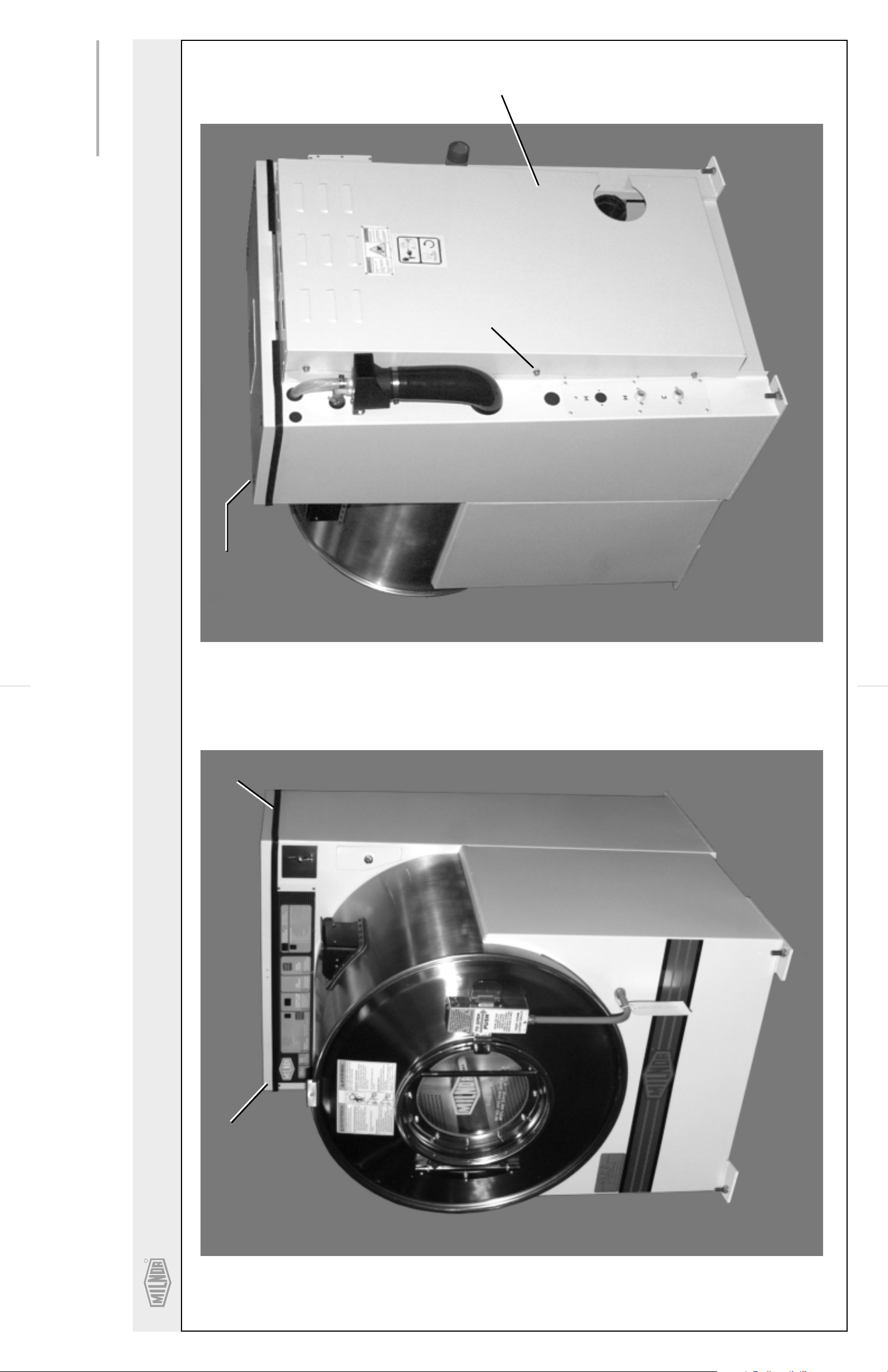
Parts List- Guards & Covers
Comments
Description
Find the correct assembly first, then find the needed components. The item letters (A, B, C, etc.) assigned to
assemblies are referred to in the "Used In" column to identify which components belong to an assembly. The item
Part Number
Item
Used In
numbers (1, 2,3, etc.) assigned to componentsrelate the parts list to the illustration.
.
A GGC30001 GUARDS/COVERS INSTALL
B ASC30001 3022C4E FRONT/REAR CONSOLE ASY
--------------------------------------------------------------------ASSEMBLIES------------------------------------------------------------------
.
-------------------------------------------------------------------COMPONENTS------------------------------------------------------------------
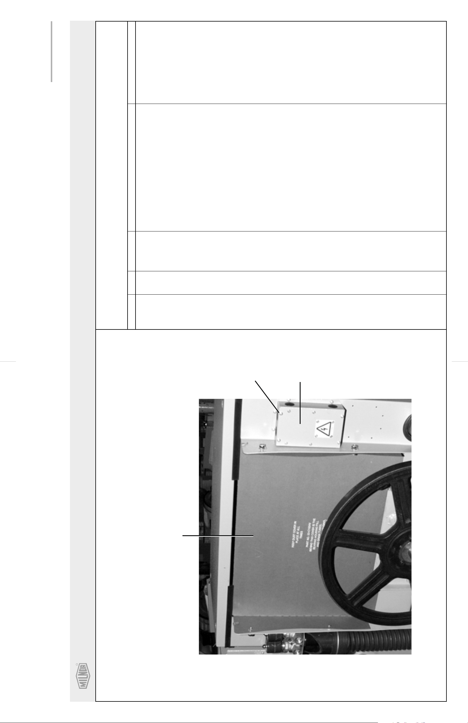
all 1 02 03497B GUARD REAR BELT FULL
all 2 W2 03699A *CONSOLE TOP WELDMENT
all 3 02 03344 TRIM=REAR CONSOLE TOP 7FT/PC
all 4 03 C4X7 COVER:SYSTEM 7 LIQUID SUPPLY
all 5 03 C1824V DUST COVER-30"V6J BELT
all 6 15K120 HXCAPSCR 3/8-16UNC2AX2 GR5 ZIN
all 7 17N070P RETAIN NUT 3/8-16 #S10100-27
all 8 15P200 TRDCUT-F HXWASHD 3/8-16X3/4NIK
all 9 15U346 FLAWASH 7/8X3/8X.030 NATURAL N
all 10 15P185 TRDCUT-F HXHD 1/4-20UNC2AX3/4
10
TYPICAL
4
Pellerin Milnor CorporationPellerin Milnor Corporation
R
Guards & Covers
30015 & 30022C4E
P. O. Box 400, Kenner, LA 70063-0400
NOTE: KEEP DUST COVER IN PLACE AT ALL TIMES. REMOVE FOR
SERVICING. BEHIND THIS COVER ARE THE BEARING
HOUSING FILL AND DRAIN TUBES.
5
DUST COVER

7
BIWUUI02 (Published) Book specs- Dates: 20001108 / 20001108 / 20100609 Lang: ENG01 Applic: WUU
About the Forces Transmitted by Milnor® Washer-extractors
During washing and extracting, all washer-extractors transmit both static and dynamic (cyclic)
forces to the floor, foundation, or any other supporting structure. During washing, the impact of
the goods as they drop imparts forces which are quite difficult to quantify. Size for size, both
rigid and flexibly-mounted machines transmit approximately the same forces during washing.
During extracting, rigid machines transmit forces up to 30 times greater than equivalent flexiblymounted models. The actual magnitude of these forces vary according to several factors:
• machine size,
• final extraction speed,
• amount, condition, and type of goods being processed,
• the liquor level and chemical conditions in the bath preceding extraction, and
• other miscellaneous factors.
Estimates of the maximum force normally encountered are available for each Milnor® model and
size upon request. Floor or foundation sizes shown on any Milnor® document are only for ongrade situations based only on previous experience without implying any warranty, obligation, or
responsibility on our part.
1.
Rigid Machines
Size for size, rigid washer-extractors naturally require a stronger, more rigid floor, foundation, or
other supporting structure than flexibly-mounted models. If the supporting soil under the slab is
itself strong and rigid enough and has not subsided to leave the floor slab suspended without
support, on grade installations can often be made directly to an existing floor slab if it has enough
strength and rigidity to safely withstand our published forces without transmitting undue
vibration. If the subsoil has subsided, or if the floor slab itself has insufficient strength and
rigidity, a deeper foundation, poured as to become monolithic with the floor slab, may be
required. Support pilings may even be required if the subsoil itself is “springy” (i.e., if its
resonant frequency is near the operating speed of the machine). Above-grade installations of rigid
machines also require a sufficiently strong and rigid floor or other supporting structure as
described below.
2.
Flexibly-mounted Machines
Size for size, flexibly-mounted machines generally do not require as strong a floor, foundation, or
other supporting structure as do rigid machines. However, a floor or other supporting structure
having sufficient strength and rigidity, as described in Section 3, is nonetheless vitally important
for these models as well.
3.
How Strong and Rigid?
Many building codes in the U.S.A. specify that laundry floors must have a minimum live load
capacity of 150 pounds per square foot (732 kilograms per square meter). However, even
compliance with this or any other standard does not necessarily guarantee sufficient rigidity. In
any event, it is the sole responsibility of the owner/user to assure that the floor and/or any other
supporting structure exceeds not only all applicable building codes, but also that the floor and/or
any other supporting structure for each washer-extractor or group of washer-extractors actually
has sufficient strength and rigidity, plus a reasonable factor of safety for both, to support the
weight of all the fully loaded machine(s) including the weight of the water and goods, and
including the published 360º rotating sinusoidal RMS forces that are transmitted by the
machine(s). Moreover, the floor, foundation, or other supporting structure must have sufficient
PELLERIN MILNOR CORPORATION
About the Forces Transmitted by Milnor® Washer-extractors
8
rigidity (i.e., a natural or resonant frequency many times greater than the machine speed with a
reasonable factor of safety); otherwise, the mentioned 360º rotating sinusoidal RMS forces can be
multiplied and magnified many times. It is especially important to consider all potential vibration
problems that might occur due to all possible combinations of forcing frequencies (rotating
speeds) of the machine(s) compared to the natural frequencies of the floor and/or any other
supporting structure(s). A qualified soil and/or structural engineer must be engaged for this
purpose.
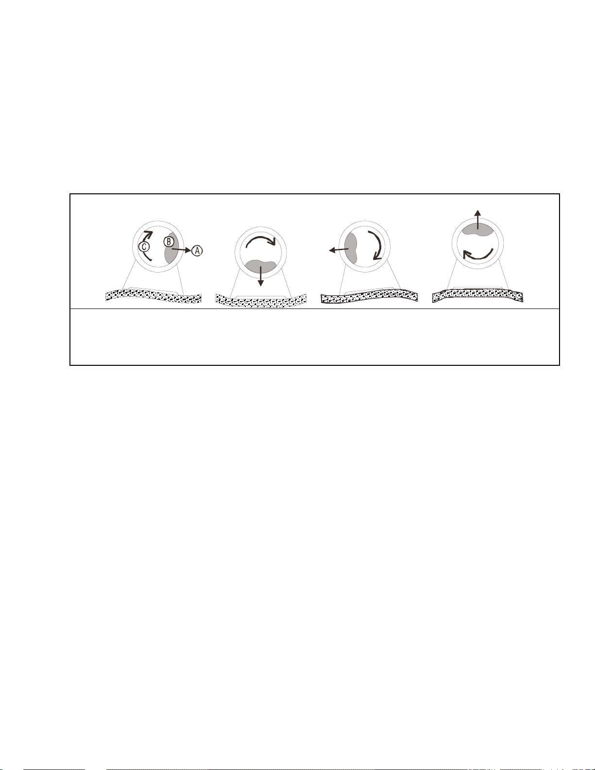
Figure 1: How Rotating Forces Act on the Foundation
Typical Machine
Legend
A. Direction of force
B. Load
C. Rotation (Frequency = RPM / 60)
.
Figure 1 above is intended to depict both on-grade and above-grade installations and is equally
applicable to flexibly-mounted washer-extractors, as well as to rigid models installed either
directly on a floor slab or on a foundation poured integrally with the slab. Current machine data is
available from Milnor® upon request. All data is subject to change without notice and may have
changed since last printed. It is the sole responsibility of every potential owner to obtain written
confirmation that any data furnished by Milnor® applies for the model(s) and serial number(s) of
the specific machines.
— End of BIWUUI02 —
PELLERIN MILNOR CORPORATION

9
BIUUUI02RC (Published) Book specs- Dates: 20110131 / 20110131 / 20110131 Lang: ENG01 Applic: RMC
Understanding the Tag Guidelines for the Models Listed Below
30010CGE 30015C4A 30015C4E 30015C4T 30015CGE 30022C4A 30022C4E
30022C4T
Several installation guidelines and precautions are displayed symbolically, on tags placed at the
appropriate locations on the machine. Some are tie-on and others are adhesive tags. Tie-on tags
and white, adhesive tags may be removed after installation. Yellow adhesive tags must remain on
the machine.
PELLERIN MILNOR CORPORATION
Understanding the Tag Guidelines for the Models Listed Below
This tag is usually wrapped around a motor housing. If the motor
10
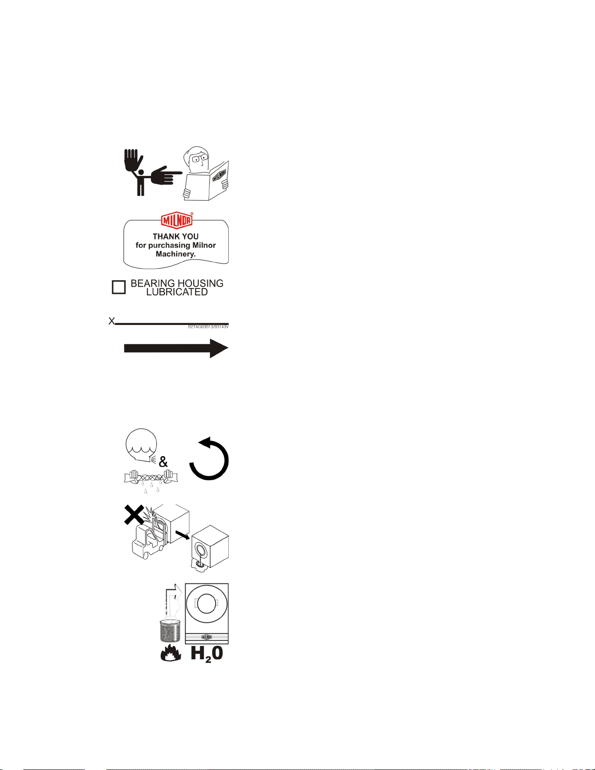
Most tags contain only symbols (no words). A few are worded. The explanations below, start
with the tag part number (displayed on the tag). If a tag contains no words, the meaning of the tag
is explained below. If the tag contains words, the explanation below simply repeats the wording.
Display or Action Explanation
Read the manual before proceeding. This symbol appears on
most tags. The machine ships with a complete set of manuals.
The safety, installation, and electrical schematic manuals are
particularly important to installers.
B2TAG88005: This carefully built product was tested and
inspected to meet Milnor performance and quality standards by
B2TAG93013: This bearing housing was lubricated at the
Milnor factory before shipment.
B2TAG94081: Motor must rotate in this direction. On single
motor washer-extractors and centrifugal extractors, the drive
motor must turn in this direction during draining and extraction.
turns in the opposite direction when the machine is first tested,
the electrical hookup is incorrect and must be reversed as
explained in the schematic manual.
B2TAG94097: The cylinder must rotate counterclockwise
during draining and extraction (spin) when viewed from here
(rear of machine). Otherwise, reverse the electric power
connections, as explained in the schematic manual.
PELLERIN MILNOR CORPORATION
B2TAG94099: Do not strike the shell door when fork-lifting.
This can cause the door to leak.
B2T2001013: Hot water connection.
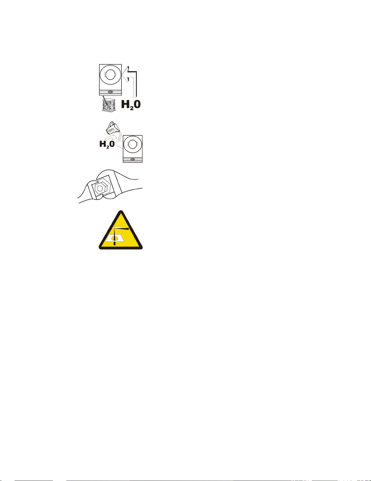
Otherwise, you may twist components, such as valves, damaging
Ensure the chemical system prevents dribbling, siphoning, or any
11
Display or Action Explanation
B2T2001014: Cold water connection.
B2T2001016: Flushing water connection. This is the water that
goes into the supply compartment or pumped chemical manifold
to flush chemicals into the machine.
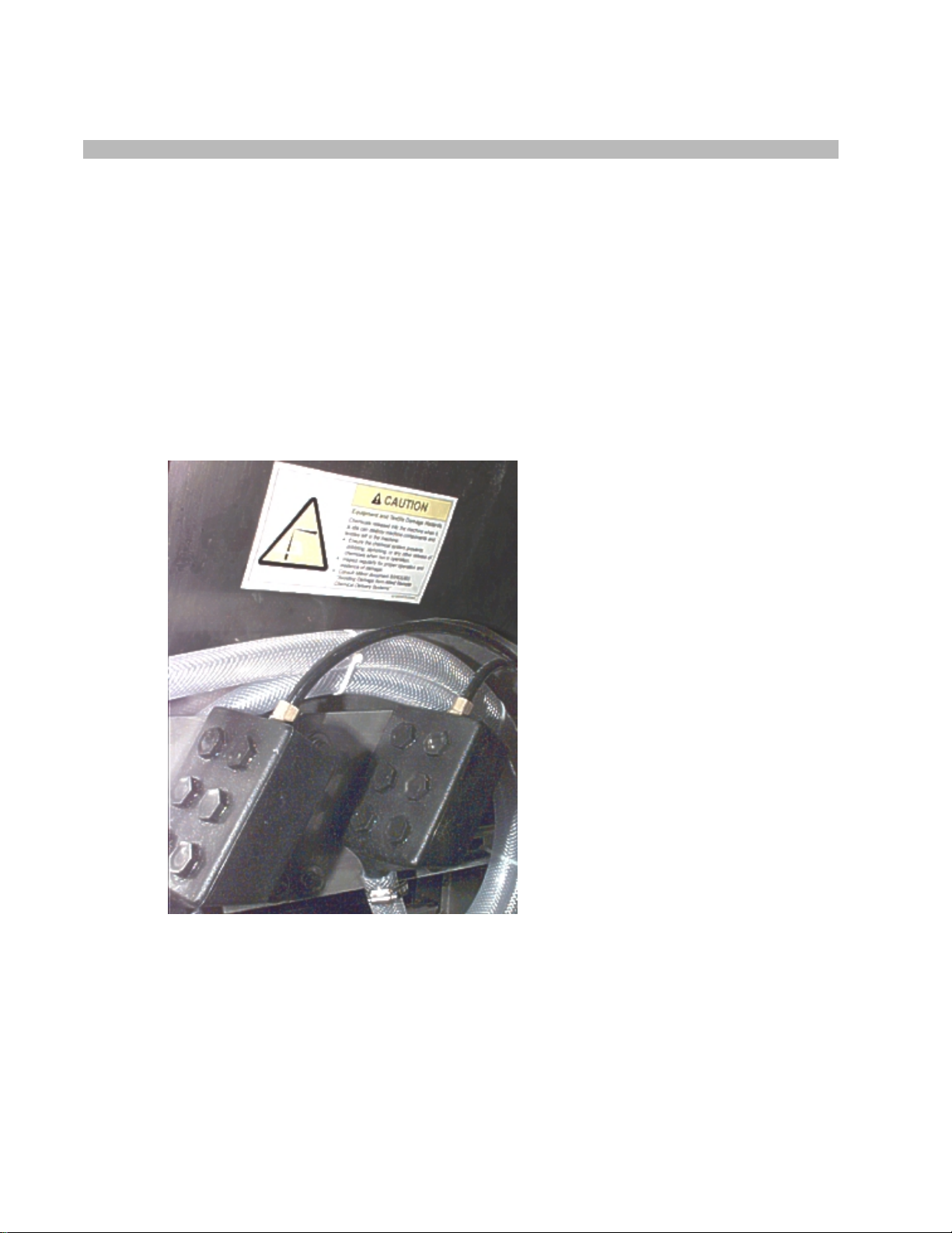
B2T2003001: Hold the side of the connection stationary with a
wrench as you tighten the connection with another wrench.
them.
B2T2003002: CAUTION: Equipment and Textile Damage
Hazards—Chemicals leaked into the machine, particularly when
it is idle, can destroy machine components and textiles left in the
machine.
other unintentional release of chemicals.
Inspect regularly for proper operation and evidence of damage.
Consult Milnor document BIWUUI03 “Avoiding Damage from
Allied Remote Chemical Delivery Systems”.
— End of BIUUUI02 —
PELLERIN MILNOR CORPORATION
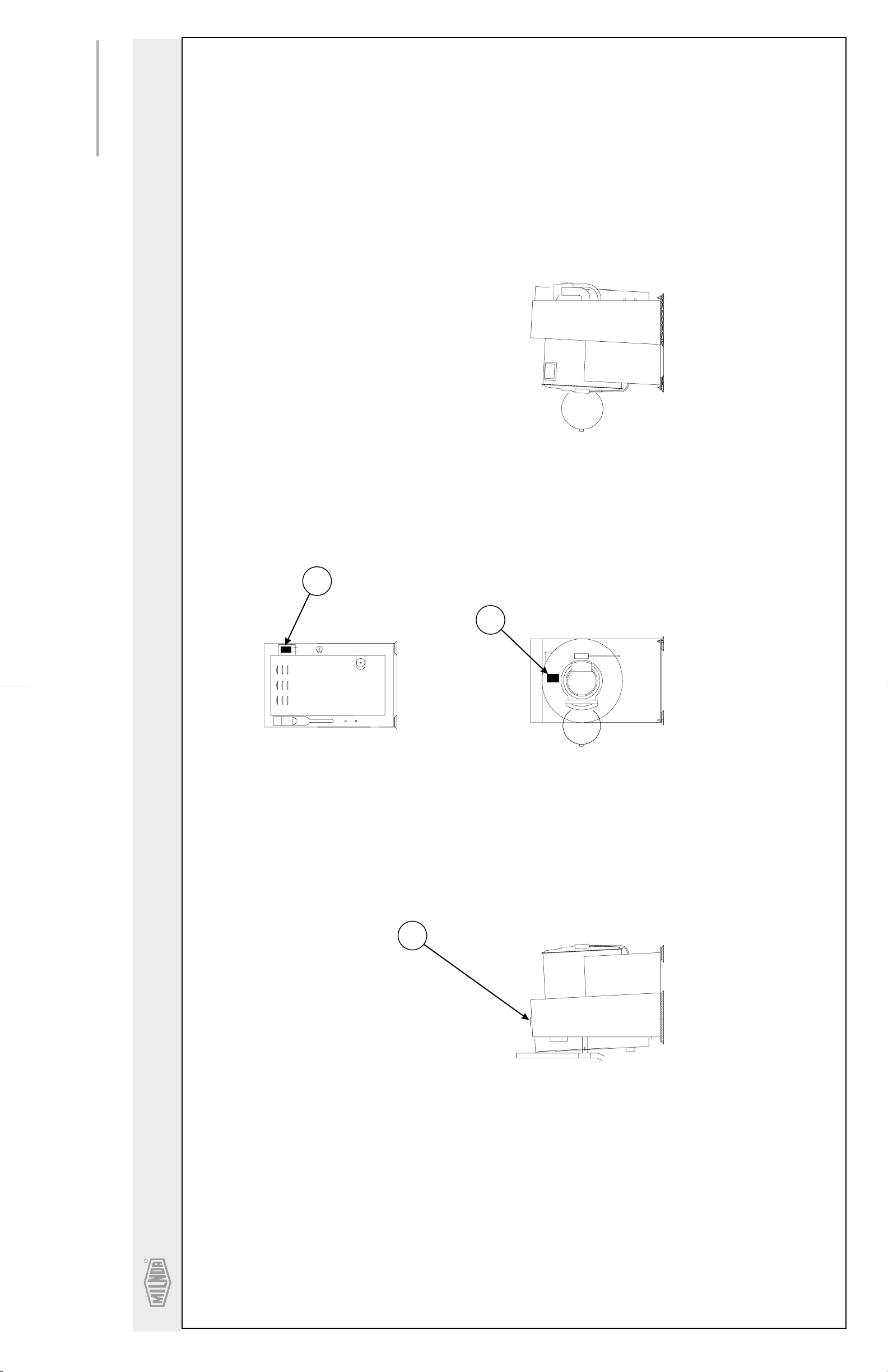
(Sheet 1 of 2)
12
BMP030012/2003202V
Litho in U.S.A.
RIGHT SIDE VIEWLEFT SIDE VIEW
10
REAR VIEW
50
FRONT VIEW
P. O. Box 400, Kenner, LA 70063-0400
Pellerin Milnor CorporationPellerin Milnor Corporation
On Top
60
R
Safety Placard Use and Placement
30010, 30015 & 30022C4E
unreadable.
. Replace placard immediately, if removed or
Notes:
1
Mounting holes are provided on machine.
If aluminum placard use #8 self-tapping screws.
. Approximate locations of placards are shown.
2
R
13
Pellerin Milnor CorporationPellerin Milnor Corporation
P. O. Box 400, Kenner, LA 70063-0400
BMP030012/2003202V
(Sheet 2 of 2)
Litho in U.S.A.
Find the correct assembly first, then find the needed components. The item letters (A, B, C, etc.) assigned to
Parts List—Safety Placard Placement
assemblies are referred to in the "Used In" column to identify which components belong to an assembly. The item
numbers (1, 2,3, etc.) assigned to componentsrelate the parts list to the illustration.
Used In
.
---------------------------------------------------------------------ASSEMBLIES------------------------------------------------------------------
-------------------------------------------------------------------COMPONENTS-----------------------------------------------------------------all 10 01 10375C 2001262B NPLT:E-HAZARD SM VERTCL-TCATA
all 50 01 10707A 2002344B NPLT:WARNING FRT SHELL COIN OP
all 60 01 10708A 2002344C NPLT:REAR WARNINGS COIN OP
Item
Part Number
Description
none
Comments
BIWUUI03 (Published) Book specs- Dates: 20030306 / 20030306 / 20030306 Lang: ENG01 Applic: WUU
14
Avoiding Damage From Allied Remote Chemical Delivery Systems
Milnor® does not manufacture or supply remote chemical delivery systems and this document is
meant only to illustrate some of the possible problems that can be minimized during installation
of such systems by the chemical supply company. Milnor washer-extractors and CBW
washers (tunnels) are available with convenient inlets for such systems (see Figure 1). Most
common of the types of systems currently used in commercial laundering operations are pumped
chemical systems. Other types, such as constant pressure, re-circulating ring main systems have
also been, and may continue to be used with Milnor equipment.
This document warns about some of the possible hazards posed by chemical systems and lists
certain requirements needed to minimize those hazards. The procedures for interfacing with allied
chemical systems and information pertinent to chemical use in general are provided elsewhere in
the product manuals (see Note 1).
Figure 1: Pumped Chemical Inlets on CBW Batch Washer
®
batch
Note 1:
permitting acid sours to react with hypo chlorite) due to incorrect formulation can also be hazardous.
Information pertinent to chemical u se is provided elsewhere in the product manuals.
1.
How a Chemical System Can Damage the Machine It Serves
Misuse of laundering chemicals (such as injecting excessive concentrations of chl orine bleach or
Milnor has manufactured washer-extractors and tunnel washers with the same stainless steel
specification since its founding. Every batch of steel used is certified and documented by the steel
mill. Testing of samples damaged by corrosion have, in every case, proven the steel to be well
within the AISI 304 specification.
PELLERIN MILNOR CORPORATION
Avoiding Damage From Allied Remote Chemical Delivery Systems
15
Chemical products commonly found in the laundry industry, when used in established dosages
and proper operating parameters, under the auspices of an experienced chemical specialist, should
produce satisfactory results, with no consequential detrimental effects. The industry has published
standards in Riggs and Sherrill, “Textile Laundering Technology”. However, the stainless steel
can be damaged and even destroyed by abnormal contact with chlorine bleach, hydrofluosilicic
acid and other commonly used chemicals, as will occur if chemicals are unintentionally leaked
into the machine, particularly when it is no longer in use and especially when machine surfaces
are dry.
Some chemical systems have been found to permit chemicals to dribble from the supply lines, or
worse, to siphon from the supply tank into the machine, during operation and long after the
system is shut down—as after working hours and during weekends. If this occurs, deterioration
(rusting) of the stainless steel and damage to any textiles therein will inevitably result. If this
condition goes undetected, machine damage is likely to be catastrophic. No machine is
immune to such damage.
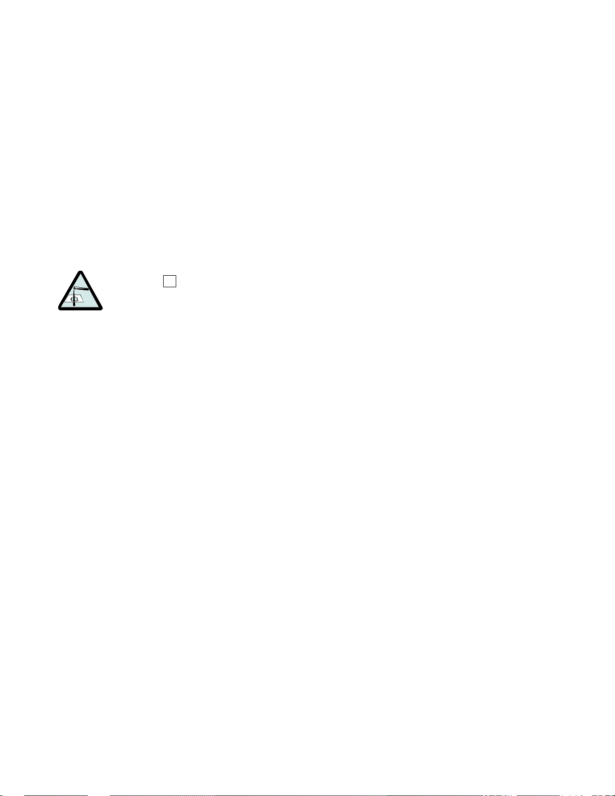
CAUTION 1 : Equipment and Textile Damage Hazards
—Chemicals leaked into the
machine, particularly when it is idle can destroy machine components and textiles left in the
machine. Pellerin Milnor Corporation accepts absolutely no responsibility for damage to its
equipment or to textiles therein from abnormal contact with chemicals.
• Ensure that the chemical system prevents unin ten ti ona l rele ase of chemicals.
• Inspect regularly for proper operation and evidence of damage.
2.
Requirements for Chemical Systems Used With Milnor Machines
It is the responsibility of the chemical system manufacturer and supplier to ensure that their
system is safe for personnel and equipment. Some important points are described below.
2.1.
Ensure the System Cannot Siphon.
—The supply system must be designed to
counteract any siphoning that could occur as a result of having a sealed supply line between the
bottom of the chemical tank and the internal machine connection at the drain trough. As shown in
the Figure 2 examples, if the pump (P) and/or the valving does not provide positive closure and
there is no vacuum breaker protection, siphoning is likely to occur. In each of the Figure 2
illustrations, the volume of chem ical in the tank above th e siphon level (S), and indi ca ted by
shading, will flow into the machine.
PELLERIN MILNOR CORPORATION
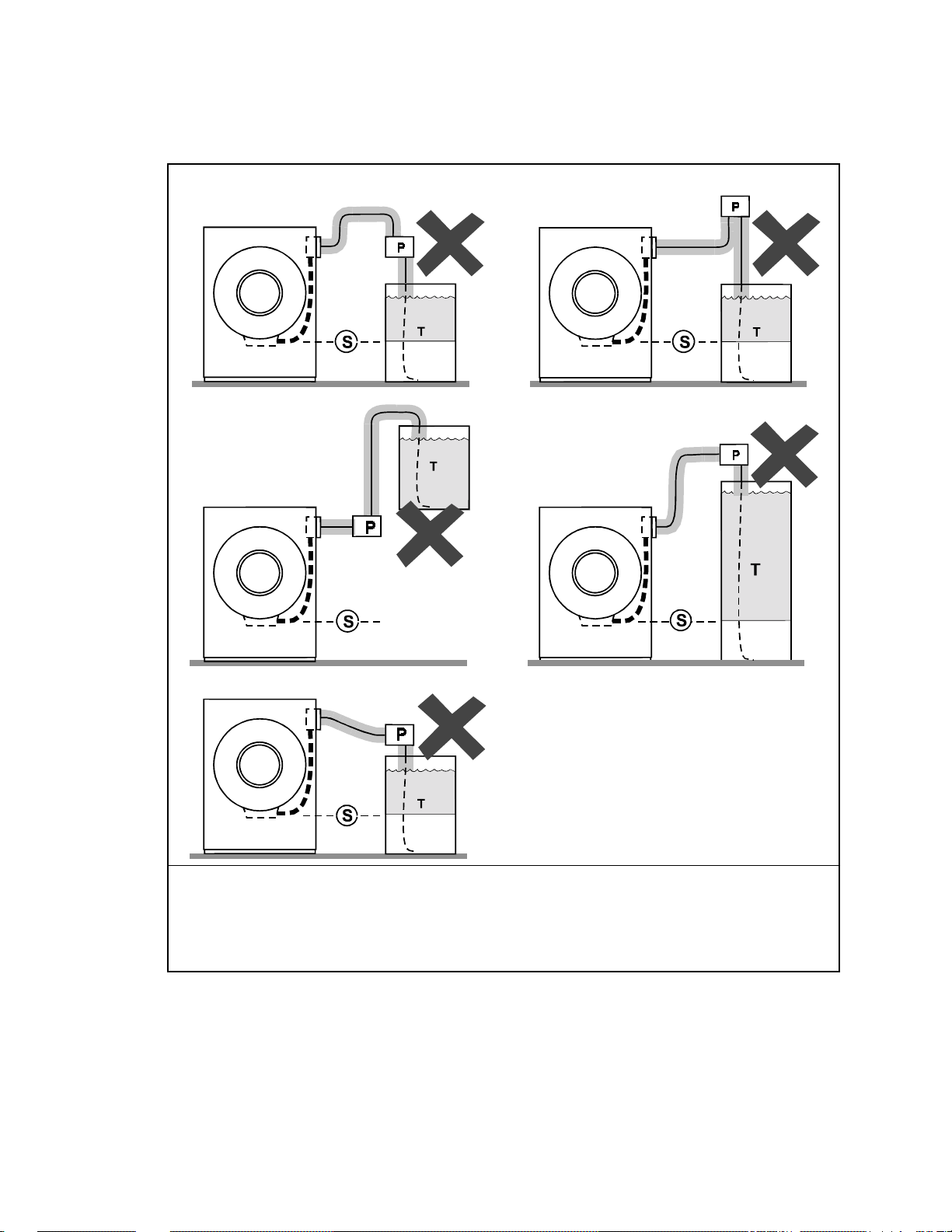
Figure 2:
16
Siphoning From the Chemical Tank into the Machine
Examples
Legend
Pump
P.
Siphon level. Shading indicates the chemical delivery line and tank content that can siphon into
S.
the machine.
Chemical tank
T.
2.2.
Ensure the Chemical Lines Cannot Dribble
—The pumped chemical system may
provide a means of positively closing the chemical line at the pump location, but not at the
injection site. Hence, any concentrated chemical that remains in the injection line between the
pump and the machine is free to flow into the machine. Some examples of this are shown in
Figure 3.
PELLERIN MILNOR CORPORATION

Avoiding Damage From Allied Remote Chemical Delivery Systems
17
Figure 3:
Dribbling From Chemical Supply Line Into Machine
(assumes positive closure at the pump)
Examples
Legend
Portion of supply line, the contents of which can dribble into the machine
D.
Pump
P.
Chemical tank
T.
3.
Design and Installation Recommendations
It is the responsibility of the chemical system manufacturer and supplier to use whatever
measures are necessary to ensure that their system is safe for personnel and equipment. The
following are some of the possible methods the manufacturer or supplier may wish to use, as
appropriate.
3.1.
Siphoning: Positively close the line.
—If the pump does not provide positive closure
when the system is off, employ a shutoff valve in the line to serve this purpose.
3.2.
Siphoning: Break the siphon.
—Provide an air gap or vacuum breaker in the chemical
delivery line. This must be located above the “full” line of the tank.
3.3.
Dribbling: Flush the entire chemical delivery line.
—If any concentrated chemical
that remains in the injection line between the pump and the machine is free to flow into the
machine, employ a system that flushes the entire line between the pump and the injection point
with fresh water after each injection.
PELLERIN MILNOR CORPORATION
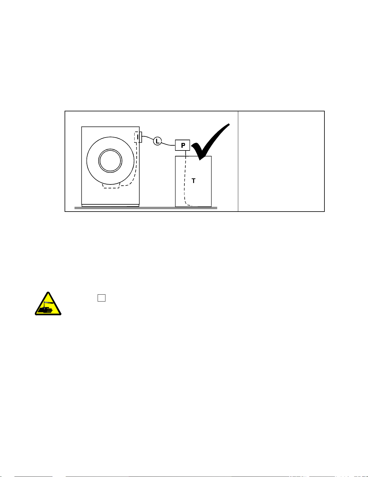
3.4.
18
Dribbling: Locate the entire chemical line below the machine inlet.
—
Assuming the chemical system does not retain any line pressure and that the pump provides
positive closure when the system is off, locate the entire chemical delivery line below the level of
the chemical inlet. An example of this is shown in Figure 4.
Figure 4:
Locating a Pumped Chemical System With Positive
Closure To Protect Against Machine Damage
Example of Correct Placement Legend
Chemical inlet on
I.
machine
Chemical delivery line
L.
Pump with positive
P.
closure when system is
off
Chemical tank
T.
4.
Guarding Against Leaks
All personnel who may work with the chemical system (e.g., chemical system manufacturer,
chemical system supplier, chemical supplier, operator, maintenance personnel) should be vigilant
in observing for leaks in the system. When connecting, or reconnecting chemical lines, whether at
installation, after taking samples, or when replacing components, at a minimum ensure that:
1. the proper components are used,
2. all connections are the proper fit, and
3. all components are securely connected.
CAUTION 2 : Injury and Damage Hazards
—Chemicals leaking from a chemical system
may be corrosive or toxic. Such chemicals can injure personnel and damage equipment.
• Use care when connecting chemical lines.
• Inspect regularly for leaks.
— End of BIWUUI03 —
PELLERIN MILNOR CORPORATION

Section 1
19
Service and Maintenance
Preventive Maintenance
20
BIRQUM01 (Published) Book specs- Dates: 20050302 / 20050302 / 20050302 Lang: ENG01 Applic: RQN
Preventive Maintenance
1. Lubrication Guidelines
As required by the warranty, to ensure safe operation, and to achieve optimum performance and
service life from Milnor® washer-extractors, the schedules, instructions, and precautions herein
must be strictly followed.
WARNING 1 : Entangle and Crush Hazard—Belts and pulleys can entangle and crush
body parts.
• Lock OFF and tag out power at the wall disconnect before servicing, except where
specifically instructed otherwise in this section.
• Insure belt and pulley guards are in place during service procedures.
• Permit only qualified maintenance personnel to perform these procedures.
2. 36021C4E Main Bearing Maintenance
36021C4E main bearing housings are oil-filled and require periodic draining and refilling (see
below).
See the appropriate “MAIN BEARING ASSEMBLY” (see Table of Contents) during this
procedure.
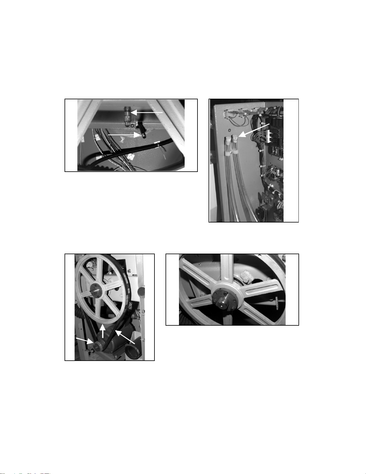
1. Remove the drain plug on the bottom of the main bearing housing and allow the bearing
housing to drain completely (Figure 1). Inspect the leak-off, drained oil, and magnetic drain
plug for water and/or metal particles. Install the drain plug. Water and/or metal particles can
indicate worn or damaged seals and bearings.
2. Locate the two 1/2" plastic tubes secured to the electrical control chassis (Figure 2). Clean the
surrounding area and remove the cork stoppers from each.
3. Strictly following lubrication specifications, refill the bearing housing. After refilling the
bearing housing, re-install the cork stoppers and clean any excess lubricant from the machine.
PELLERIN MILNOR CORPORATION

Preventive Maintenance
21
3. Preventive Maintenance Schedule
Table 1: Preventive Maintenance Checklist
Component Action Frequency Specifications/Figure
Bearing
Housing
Oil Remove fill, vent and drain
stoppers. Refill 22 ounces (634
grams)
Every four
months
High quality SAE 30 to 50
(ISO 100 - 220) single weight
heavy duty motor oil (nondetergent if available). See
"Oil Drain and Water Leakoff" and also see
"30022C4x,..Fill/Vent Hoses"
Drive Train
Drive
Inverter
Hoses,
Clamps, and
Connections
Belts and pulleys Check for wear, replace as
required
Motors (if
equipped with
grease fittings)
See "Baldor Motor
Maintenance...," in this manual
(See Note 3)
(See Note 2)
Inverter Verify fan operation. Vacuum
out inverter vents.
Inlet, drain, and
chemical hoses
Check for leaks, cracks and
bulges
and connections
Monthly See "Drive Train Pulleys and
Belts"
Every three
Months
See motor nameplate. If not
specified, use Shell Alvania
(or equivalent). See "Motor
Grease Points"
Monthly See "Inverter Maintenance
Points"
Monthly
Bolts Foundation Check bolt tightness and wear Monthly See dimensional drawings
Rear bearing
reinforcement
plate and
throughout
machine
See "30022C4x,...Rear
Reinforcement Plate" for
36021C4E and 36026V5J
machines, or "42026V6J Rear
Reinforcement Plate" for
42026V6J machines.
Note 1: Monthly/200 hours = Once a month or once every 200 operating hours, whichever comes first.
Note 2: Do not over-lubricate motors. Over-lubrication of a motor can seriously damage it by forcing
grease into motor windings.
Note 3: If motor manufacturer's instructions conflict with manual section MSSM0274AE, follow
manufacturers instructions. Motors are warranted by the manufacturers, not by Milnor.
PELLERIN MILNOR CORPORATION
4. Maintenance Points
22
Preventive Maintenance
Figure 1: 30022C4x, 30022T5x, 36021C4E and
36026V5J Oil Drain and Water Leak-off
Figure 3: Drive Train Pulleys and
Belts (30022V6J shown)
Figure 4: 30022C4x, 30022T5x, 30022V6J, 36021C4E
and 36026V5J Rear Bearing Reinforcement Plate
(30022VxJ shown)
Figure 2: 30022C4x, 30022T5x,
36021C4E and 36026V5J Oil
Fill/Vent Hoses (use either hose
for filling)
PELLERIN MILNOR CORPORATION
Preventive Maintenance
23
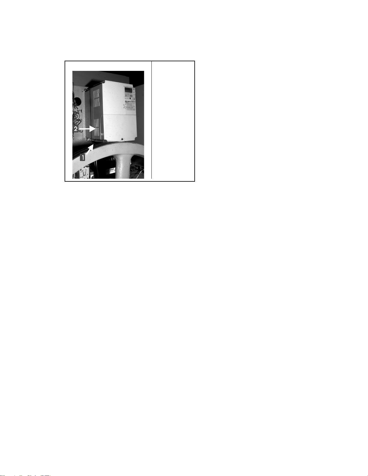
Figure 5: Inverter Maintenance Points
36021C4E Inverter Legend
1. Fan
2. Vent
.
— End of BIRQUM01 —
PELLERIN MILNOR CORPORATION
 Loading...