


Pellicon® 2 and 3 Mini Holder
User Guide

Notice
The information in this document is subject to change without notice and should not be
construed as a commitment by Millipore Corporation. Millipore Corporation assumes no
responsibility for any errors that may appear in this document. This manual is believed
to be complete and accurate at the time of publication. In no event shall Millipore
Corporation be liable for incidental or consequential damages in connection with or
arising from the use of this manual.

Pellicon-2 and 3 Mini Holder User Guide 3
Contents
Unpacking ...............................................................................................5
Plumbing and Instrumentation ..............................................................6
Assembling the Pellicon 2 and 3 Mini Holder ......................................7
Feed and Retentate Fitting Connections ................................ 7
Permeate Fitting Connections ................................................7
Connecting Pressure Gauge Adapter Fittings
to FEED and RETENTATE Fittings .........................................8
Connecting the Pressure Gauge ............................................9
Connect the Permeate Fittings ............................................. 10
Inserting the Pellicon Cassettes ...........................................10
Attaching the End Plate ........................................................ 11
Setup for Autoclaving ..........................................................................13
Ordering Information ............................................................................14
Spare Parts and Accessories ...............................................14
General Limited Warranty .................................................................... 15
T echnical Assistance ...........................................................................16

4 www.millipore.com
Pellicon-2 and 3 Mini Holder User Guide 5
Unpacking
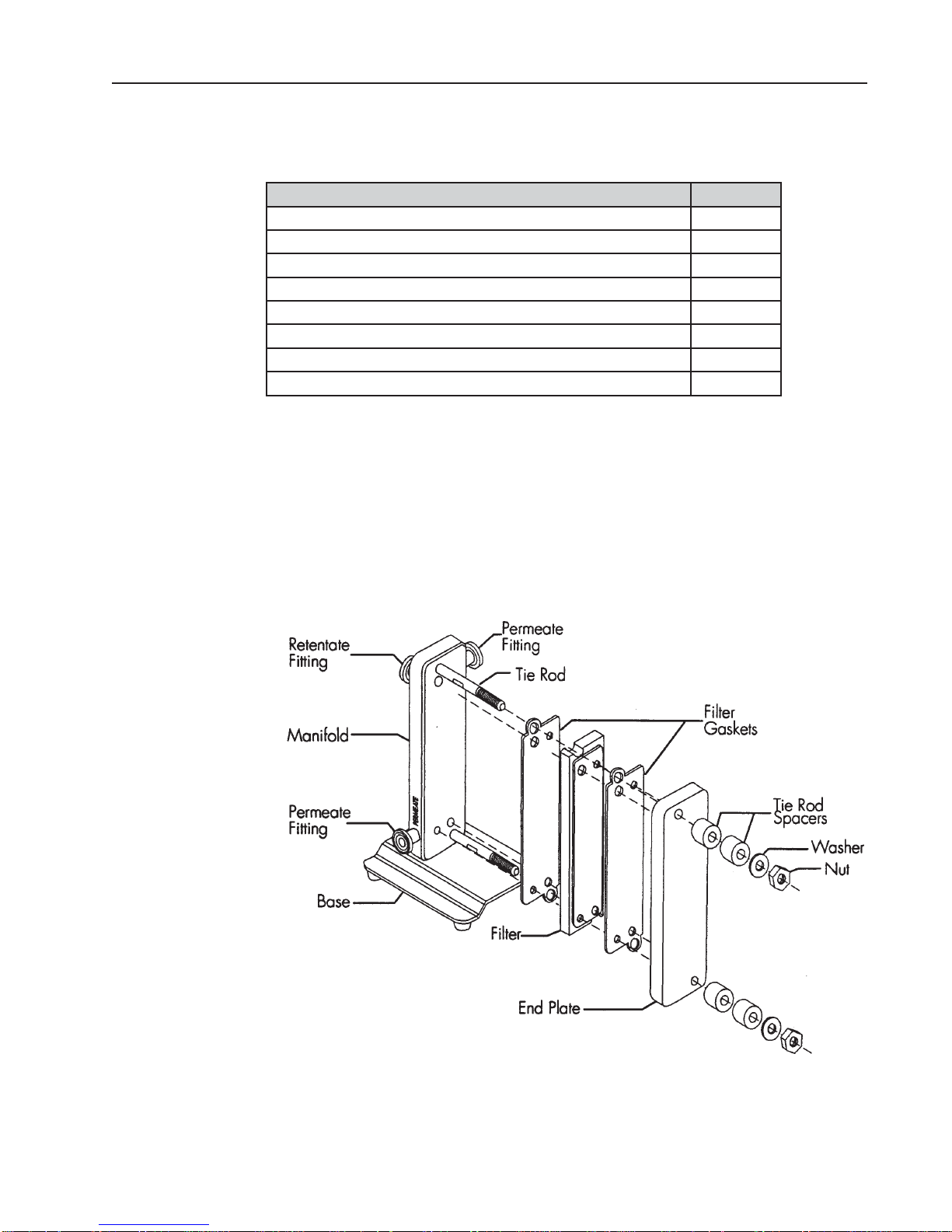
The Pellicon 2 and 3 Mini Holder comes packed in a box and includes the following items:
Description Quantity
Manifold with two tie rods, attached to a base 1
End plate 1
Tie rod spacer 4
3/8 inch Flat washer 2
3/8-16 UNC Hex nut, silicon bronze 2
½-inch Sanitary gasket 4
Fractional sanitary clamp 4
9/16 inch Deep socket 1
Unpack the holder and deep socket. 1.
Remove the FEED and RETENTATE fittings from the holder.2.
Loosen and remove the two nuts on the tie rods. 3.
Remove the washers, spacers, and end plate from the holder. Remove the shipping 4.
insert located between the holder manifold and end plate.
Place the holder base on a level surface.5.
Exploded view of Pellicon 2 and 3 Mini HolderFigure 1:

6 www.millipore.com
Plumbing and Instrumentation
The concentration mode is the most commonly used mode for the concentration of
proteins and viruses and is shown in Figure 2 without the diafiltrate. During this mode,
material retained by the membrane (retentate) flows out of the retentate fitting and is
recirculated to the original product container. The material passing through the membrane
(permeate) flows out of the permeate outlet fitting onto the permeate collection container.
The constant volume diafiltration mode, shown in Figure 2, is used for washing product
that is retained by the membrane or for recovering additional product that is passed
through the membrane. The mode involves the addition of water or buffer to the feed
container at the same rate as permeate is being removed from the process.
Plumbing and Instrumentation DiagramFigure 2:

Pellicon-2 and 3 Mini Holder User Guide 7
Assembling the Pellicon 2 and 3 Mini Holder
Feed and Retentate Fitting Connections
Configurations for connecting fittings to the FEED and the RETENTATE fittings, shown
in Figure 3, include:
Connecting a pressure and sanitary diaphragm valve to the RETENTATE fitting, 1.
and a pressure gauge to the FEED fitting.
Connecting separate tubing to the FEED and the RETENTATE fittings.2.
Feed and Retentate Fitting ConnectionsFigure 3:
Permeate Fitting Connections
Configurations for connecting fittings to the PERMEATE fittings, shown in Figure 4,
include:
Connecting the two PERMEATE fittings together with tubing using a tee or Y 1.
connection.
Connecting separate tubing to the two PERMEATE fittings.2.
Permeate Fitting ConnectionsFigure 4:

8 www.millipore.com
Connecting Pressure Gauge Adapter Fittings to FEED
and RETENTATE Fittings
The Pellicon 2 and 3 Mini Holder Pressure Gauge Adapter Fittings are short-leg tees to
keep the working fluid volume low and avoid non-sanitary low-flow areas in the piping.
Two ¾-inch sanitary gaskets and two sanitary fitting clamps are supplied with each
pressure gauge adapter fitting.
Seat a 3/4-inch sanitary gasket in the groove on the FEED fitting.1.
Hold the sanitary gasket in place and press the pressure gauge adapter fittings flange 2.
against the FEED fitting flange so the fitting branch is parallel to the holder case
and oriented as shown in Figure 5.
Note The gasket moves easily if not held in place when pressing the pressure gauge
adapter fittings fl ange against the holder fi tting fl ange.
Installing the Gasket and Positioning the Pressure Gauge Adapter FittingsFigure 5:
Secure the Pressure Gauge Adapter Fittings to the FEED fitting with the sanitary 3.
clamp, as shown in Figure 6.
Open the sanitary clamp by moving the swing bolt out of the clamp slot.4.
Place the sanitary clamp over the FEED fitting connection and close the sanitary 5.
clamp by moving the swing bolt into the clamp slot.
Hand tighten the sanitary clamp closure.6.
Repeat steps 1-3 to connect a pressure gauge adapter fittings to the RETENTATE 7.
fitting.

Pellicon-2 and 3 Mini Holder User Guide 9
Clamping the Pressure Gauge Adapter Fittings to the Mini Holder FittingFigure 6:
Connecting the Pressure Gauge
Analog and digital pressure gauges are available from Millipore.
Seat the ¾-inch sanitary gasket in the groove on the pressure gauge adapter fittings.1.
Hold the gasket in place and press the pressure gauge diaphragm against the ¾-inch 2.
side branch of the pressure gauge adapter fittings, as shown in Figure 7.
Attaching the Pressure Gauge to the Pressure Gauge Adapter FittingsFigure 7:

10 www.millipore.com
Secure the pressure gauge to the Pressure Gauge Adapter Fittings with the sanitary clamp.3.
Open the sanitary clamp by moving the swing bolt out of the clamp slot.4.
Place the sanitary clamp over the Pressure Gauge Adapter Fittings-PRESSURE GAUGE 5.
connection and close the sanitary clamp by moving the swing bolt into the clamp slot.
Hand tighten the sanitary clamp closure.6.
Repeat steps 1-3 to connect a Pressure Gauge Adapter Fittings to the 7.
RETENTATE fitting.
Connect the Permeate Fittings
Two gaskets and two clamps are supplied for attaching fittings to the two PERMEATE
fittings located on the sides of the manifold plate. The PERMEATE fittings accommodate
standard ½-inch or ¾-inch sanitary fittings and adapters.
Inserting the Pellicon Cassettes
Use one to three cassettes depending on the desired permeate flow rate. Permeate flow
rate increases as filter area increases.
Inspect the tie rods and nuts for signs of burrs or stripped threads. 1. Nuts should
turn freely on the tie rods for proper tightening of the holder.
Holding the manifold with one hand, slide the filter gasket (Pellicon 2 Cassettes only) tabs 2.
over the tie rods and press the filter gasket against the manifold, as shown in Figure 8.
Note Pellicon 2 Cassettes ONLY
The large feed and retentate holes on the fi lter gasket must align to the large feed
and retentate holes on the manifold.Millipore supplies two fi lter gaskets with each
fi lter. One fi lter gasket must be installed between each pair of fi lters, and one gasket
must be installed between each end of the fi lter and the adjacent stainless steel plate.
Inserting the Filter Gaskets and FilterFigure 8:

Pellicon-2 and 3 Mini Holder User Guide 11
Align the filter cut-outs with the tie rods, and insert the filter so it is parallel with the 3.
manifold as, shown in Figure 8.
Note The fi lter will extend beyond the edges of the manifold and end plate if the fi lter
does not properly align to the feed, retentate, and permeate holes.
Holding the manifold with one hand, slide the filter gasket (Pellicon 2 Cassettes 4.
only) tabs over the tie rods and press the filter gasket (Pellicon 2 Cassettes only)
against the filter, as shown in Figure 8.
Repeat steps 3–5 for additional cassettes.5.
Attaching the End Plate
Holding the manifold gaskets (Pellicon 2 Cassettes only) and filter(s) in place with 1.
one hand, slide the end plate holes over the tie rods, as shown in Figure 8, and press
the end plate against the filter.
Place an equal number of spacers on each tie rod depending on the number of 2.
filters in use.
Place one washer and one nut on each tie rod, as shown in Figure 8, and hand 3.
tighten.
Tighten the holder with the torque wrench and socket. The torque wrench setting 4.
for 180-200 inch-pounds (20.3-22.6 Newton-meters). Check the torque wrench
(not supplied with the holder) setting for 180-200 inch-pounds (20.3-22.6 Newtonmeters) prior to use. Refer to the next section to set the torque wrench.
Attaching the end plateFigure 9:

12 www.millipore.com
Attach the deep socket to the torque wrench by firmly pressing the deep socket onto 5.
the torque wrench drive. Attaching the deep socket may require force.
Hand tighten the nuts evenly by alternating from one nut to the other.6.
Brace the holder with one hand. With a continuous motion, turn each nut ¼ turn 7.
with the torque wrench, alternating from one nut to the other until torque wrench
“clicks” when it reaches 180-200 inch-pounds (20.3-22.6 Newton-meters).
Wait 5-10 minutes; re-torque to 180-200 inch-pounds (20.3-22.6 Newton-meters).8.
Waiting allows gasket(s) to relax before re-torquing.
Re-torque to a maximum of 200 inch-pounds (22.6 Newton-meters) as needed to 9.
create a liquid-tight seal. The torque wrench may have a fi xed head or a ratchet-style
head. If your wrench has a ratchet-style head, move lever to the right lock position
to tighten nuts and mover the lever to the left lock position to loosen the nuts.
Note Non-uniform tightening of the nuts can damage the fi lter. Non-parallel plates or
compression of the fi lter(s) at one end can cause leakage.
Setting the Torque Wrench
Pull down the spring-loaded lock collar to unlock the torque wrench.1.
Hold down the spring-loaded lock collar while turning the handle until the 180-200 2.
inch-pound (20.3-22.6 Newton-meters) mark on the wrench handle aligns with the
zero mark on the sleeve die.
Note One side of the torque wrench handle displays units as inch-pounds and the other
side displays units as Newton-meters.
Rotate the handle slightly so the lock collar springs back and locks into place. 3. When
the lock collar locks into place the handle will not rotate.
Setting the Torque WrenchFigure 10:

Pellicon-2 and 3 Mini Holder User Guide 13
Setup for Autoclaving
Remove all filters and filter gaskets from the Pellicon 2 and 3 Mini Holder before 1.
autoclaving.
Rest the holder FEED and RETENTATE fittings and the end plate on a soft 2.
material to protect the fitting faces and end plate from being scratched in the
autoclave.
Do not autoclave with the holder in an upright position, because the feet will
compress and become loose.
Autoclave the Pellicon 2 and 3 Mini Holder at 121º C to 125º C for 30 minutes per 3.
cycle.

14 www.millipore.com
Ordering Information
Description Catalogue Number
Pellicon 2 and 3 Mini Holder
Includes holder, 4 sanitary gaskets, 4 sanitary clamp fi ttings, and
assembly instructions
Spare Parts and Accessories
XX42PMINI
Description Catalogue Number
Kits for short tie rods including 2 tie rods XX42PMIST 2
Kits for long tie rods including 2 tie rods XX42PMILG 2
Stainless Steel Spacer
Stainless Steel spacers XX42PMSP 4
Nuts and Washer
4 washers 3/8 and 4 HEX silicone Bronze nuts 3/8-16 XX42MT073 4
Pressure Gauge
Pressure gauge.(0-4 bars) B26524 1
Pressure gauge (-1 / +6 bars) YFS7PGV34 1
Pressure gauge (0-2 bars) XX42PGM02 1
Stainless Steel TC Clamp
Fitting kit for pressure gauge: 2 tees/4 gaskets/4
clamps
TC Clamps 3/4 in. Stainless steel XX42T1900 4
TC Gasket
TC gasket silicone. FTPF03342 10
TC gasket EPDM. MSD1169W7 10
Valve
Stainless steel valve EPDM, diaphragm 3/4 in. TC YFS7ETC34 1
Hoses and Blank Caps
hose connector 12.5mm /TC FTPF0251 3
hose with 3/4” TC fi ttings XX42P60TC 1
TC blank cap 3/4 in. FTPF02247 4
Torque Wrench and Accessory: Socket/Rachet
torque wrench XX42PMITW 1
Socket 9/16 in. XX42PMISR 1
XX42PM001 N/A
Qty
(per kit)

Pellicon-2 and 3 Mini Holder User Guide 15
General Limited Warranty
Millipore Corporation (“Millipore”) warrants its products will meet their applicable
published specifications when used in accordance with their applicable instructions
for a period of one year from shipment of the products. MILLIPORE MAKES NO
OTHER WARRANTY, EXPRESSED OR IMPLIED. THERE IS NO WARRANTY OF
MERCHANTABILITY OR FITNESS FOR A PARTICULAR PURPOSE. The warranty
provided herein and the data, specifications and descriptions of Millipore products
appearing in Millipore’s published catalogues and product literature may not be altered
except by express written agreement signed by an officer of Millipore. Representations,
oral or written, which are inconsistent with this warranty or such publications are not
authorized and if given, should not be relied upon.
In the event of a breach of the foregoing warranty, Millipore’s sole obligation shall be
to repair or replace, at its option, the applicable product or part thereof, provided the
customer notifies Millipore promptly of any such breach. If after exercising reasonable
efforts, Millipore is unable to repair or replace the product or part, then Millipore shall
refund to the customer all monies paid for such applicable product or part. MILLIPORE
SHALL NOT BE LIABLE FOR CONSEQUENTIAL, INCIDENTAL, SPECIAL
OR ANY OTHER DAMAGES RESULTING FROM ECONOMIC LOSS OR
PROPERTY DAMAGE SUSTAINED BY ANY CUSTOMER FROM THE USE OF
ITS PRODUCTS.

Technical Assistance
For more information, contact the Millipore office nearest you. In the U.S., call
1-800-MILLIPORE (1-800-645-5476). Outside the U.S., see your Millipore catalogue for
the phone number of the office nearest you or go to our web site at www.millipore.com/
offices for up-to-date worldwide contact information. You can also visit the tech service
page on our web site at http://www.millipore.com/techservice.
Millipore and Pellicon are registered trademarks of Millipore Corporation. The M logo is a trademark of Millipore Corporation.
Copyright © 1994, 2009 Millipore Corporation. All rights reserved.
P35447 Rev C, 09/2009
 Loading...