

Millipore Milli-Q Plus Installation And Operation Manual
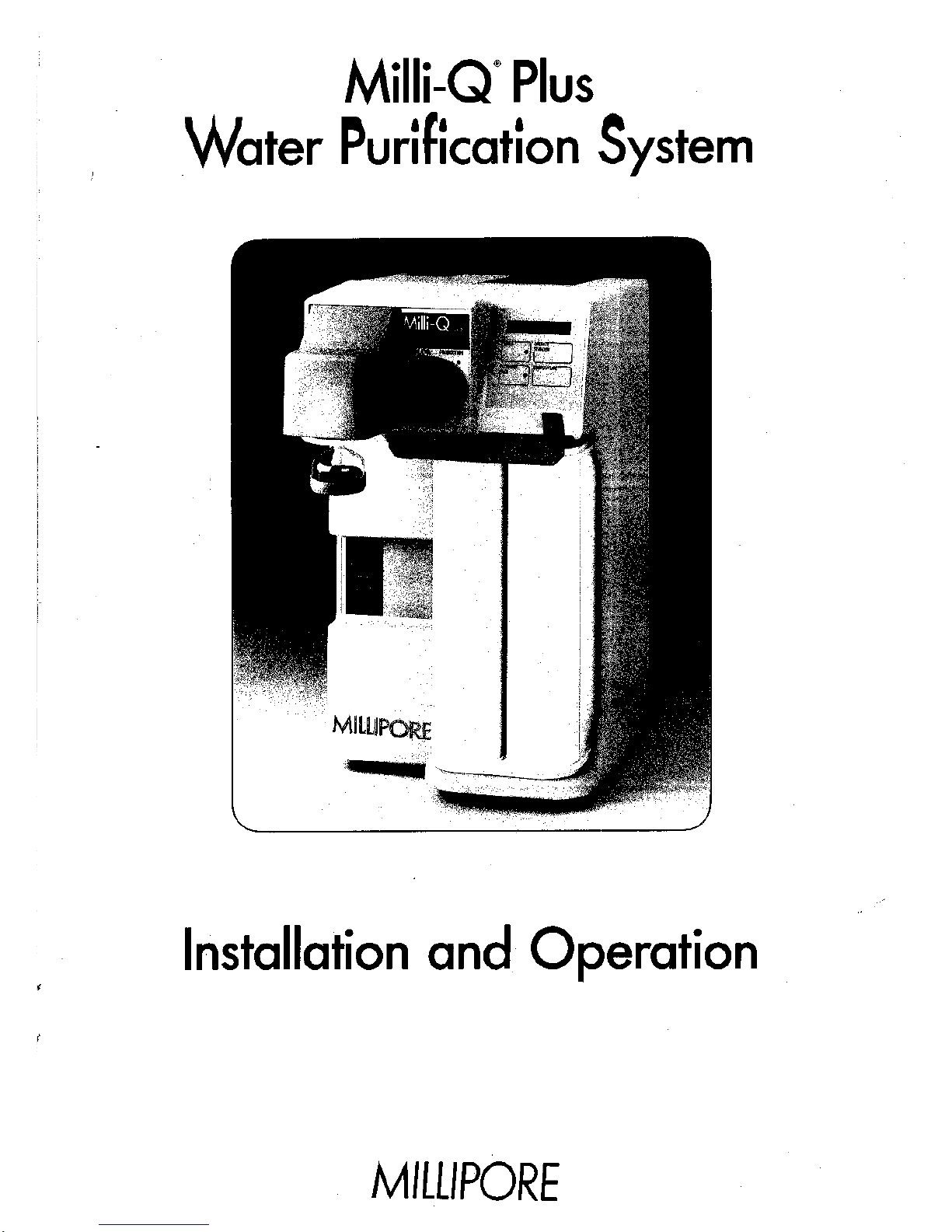
iilli-Q* Plus
Water Purification System
Installation and Operation
M1LUPORE
MILLI-Q PLUS
A. Introduction
1. System Description
2.
External Features
3. Schematic
4.
Dimensions
5. Function of Components/Controls
B.
Installation
1. Unpacking
2.
Battery Insertion
3. Water Connection
4.
Electrical Connection
5. Bench/Wall Mounting
6. Pack Installation
7.
Initial Startup
C. Operation
1. Switch On - Auto Test
2.
Operate
3. Standby
4.
Auto Recirculation (Intermittent)
5. Temperature
6. Battery
7.
Remote Standby
8. Pack Replacement
9. Final Filter - (Millipak) - Replacement
0. Maintenance
1. Access to PC Board
2.
Battery Replacement
3. Fuse Replacement
4.
Set Point Adjustment
5. Pack Replacement Frequency Setting
6. Changing the Frequency of Automatic Recirculation
1. Troubleshooting
E.
Technical Information
1. Components
2.
Specifications
3. Ordering Information
4.
Warranty
Milli-Q Plus
A. INTRODUCTION
1. System Description
The Milli-Q Plus system is a state of the art water purification
system, designed to provide the final polish to water which has
been pretreated by primary purification methods such as
Reverse Osmosis (RO), Distillation, or Deionization (DI).
The system provides ultrapure water for the laboratory for use
in critical applications requiring the absence of interfering
inorganic, organic, particulate, or microbiological material.
As a result of attention to design detail, plus strict selection
and testing of materials of construction, resins, and other
purification media, the system consistently produces water which
exceeds Type 1 standards for Reagent Grade Water.
The Milli-Q Plus system utilizes a patented purification pack
concept.
The design of this pack ensures minimal dead water
volume and as a consequence extremely low TOC values in the
purified water. The pack is constructed of pure polypropylene and
is heat welded to minimize extractables associated with gluing.
The pack concept makes maintenance of the system extremely easy.
The system indicates when the pack requires to be changed and
this can be done quickly and easily without the use of any tools.
The control box of the system utilizes a membrane keypad combined
with an alphanumeric display. The alphanumeric display allows
the user to monitor the status of the Milli-Q Plus system at all
times.
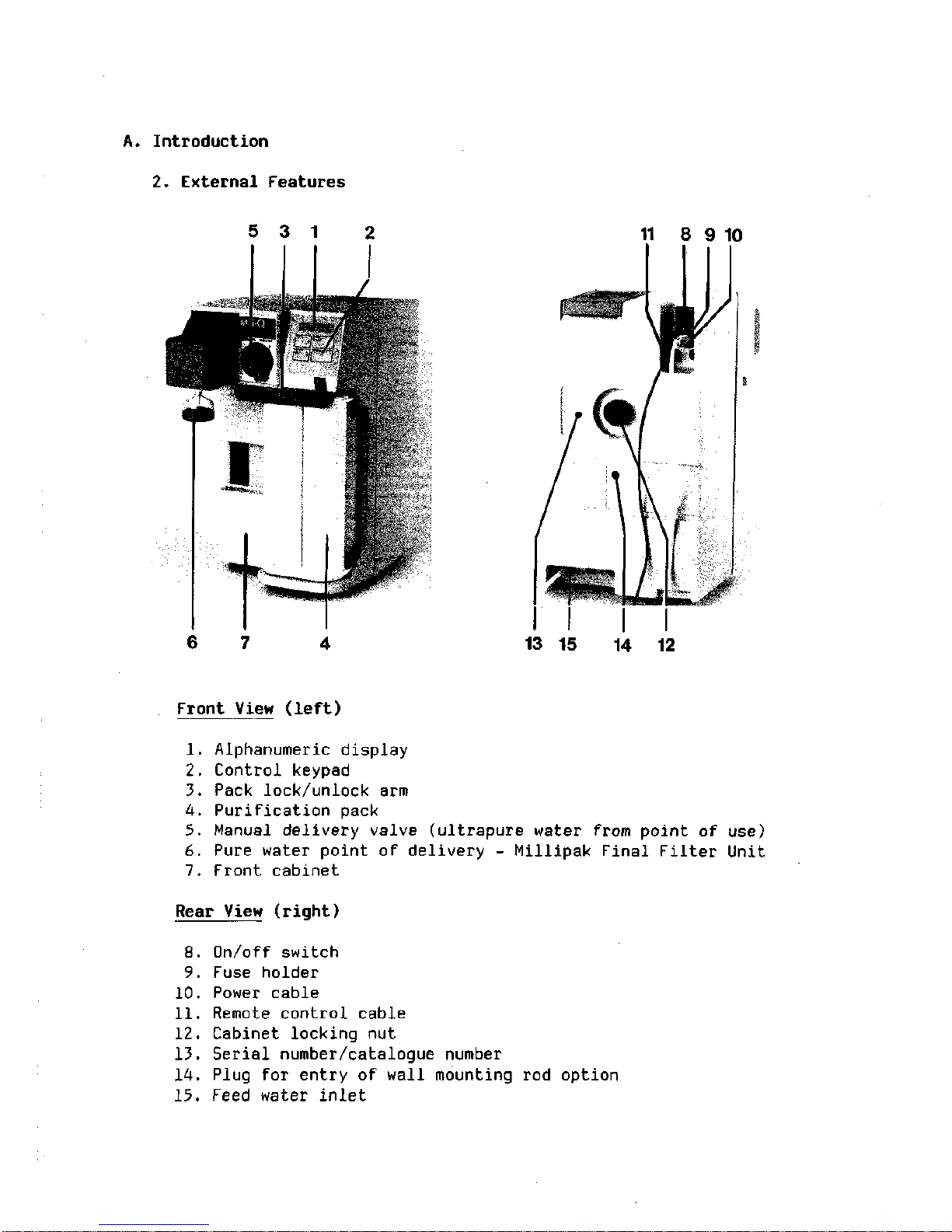
A. Introduction
2.
External Features
5 3 1
11 8 9 10
6 7
13 15 14 12
Front View (left)
1. Alphanumeric display
2.
Control keypad
3. Pack lock/unlock arm
4.
Purification pack
5. Manual delivery valve (ultrapure water from point of use)
6. Pure water point of delivery - Millipak Final Filter Unit
7.
Front cabinet
Rear View (right)
8. On/off switch
9. Fuse holder
10.
Power cable
11.
Remote control cable
12.
Cabinet locking nut
13.
Serial number/catalogue number
14.
Plug for entry of wall mounting rod option
15.
Feed water inlet
A. Introduction
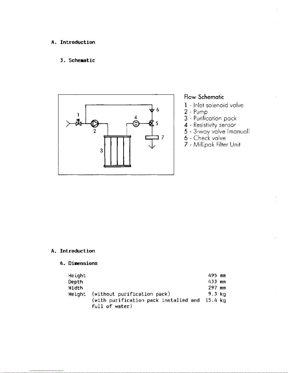
3. Schematic
Flow Schematic
1
- Inlet solenoid valve
2 - Pump
3 - Purification pack
4 - Resistivity sensor
5 - 3-way valve (manual)
6 - Check valve
7 - Millipak Filter Unit
A. Introduction
4.
Dimensions
Height 495 mm
Depth 433 mm
Width 297 mm
Weight (without purification pack) 9.3 kg
(with purification pack installed and 15.4 kg
full of water)
A. Introduction
5. Function of Components/Controls
On/Off Power Switch
This switch, located on the rear side of the unit, controls
the power to the control box. The power inlet socket is
located below the ON/OFF switch. This socket has a built
in fuse holder which contains the main fuse plus a spare.
Pump
This magnetic drive gear pump provides a draw-off flow rate of
1.5
1/min.
A built-in pressure relief valve regulates discharge
pressure to 2.8 bars (40 psi).
Sensor
The sensor, located at the outlet of the purification pack, is
electrically connected to the PC board. The sensor continuously
measures the resistivity of the product water as it exits the pack.
Meg-0-Meter Display
Resistivity of the water is displayed on the alphanumeric display
as product , Megohm x cm.
The unit is internally temperature-compensated to normalize readings
to 25° C.
Three Way Point-of-Use Valve
This PVDF valve, located behind the front panel of the unit, is
manually operated by the knob on the front panel of the unit.
This valve has two positions: RECIRCULATION - where the water
is directed through the system's recirculation loop; or
PRODUCTION - where the water is directed through the final
filter to the point-of-use.
CONTROL KEYBOARD
Operate/Standby, Operate Mode
This button, when first depressed, will switch the system to
the operate, mode. During operate mode the inlet solenoid valve
is open and the pump is running. If the manual point-of-use
valve is in the RECIRCULATION position, water will recirculate
around the system's internal recirculation loop. If the
point-of-use valve is open in the PRODUCTION position, water
will be delivered through the point-of-use. During operate,
the display will show the resistivity of the purified water
as product , Megohm x cm.
If this resistivity is less than the set point of 14 Megohm x cm
then the display of product , _ Megohm x cm will flash on and
off.
When the resistivity builds to greater than the set point,
the display of product , _ Megohm x cm becomes a steady display.
The set point is adjustable (see Section D., Maintenance, 4., Set
Point Adjustment, in this
manual).
Standby Mode
During normal operate mode, if the button is depressed, this
will switch the system to the standby mode.
During standby the inlet solenoid valve is closed and the pump
is not running. Therefore, the system is not producing water.
During standby the system will switch on automatically every
55 minutes and recirculate for 5 minutes. This inhibits bacterial
growth and degradation of pure water
Auto-Test
Each time the unit goes into operate mode, it carries out an
automatic test on the accuracy of the resistivity measuring system.
The test result is displayed for 4 seconds before the display changes
to show product water resistivity. The display should show TEST:
15 Megohm x cm.
Temperature
During the standby mode, if the temperature button is depressed,
the display will show the calibration temperature of 25° C.
(If 25° C is not displayed then there is a calibration problem.)
During operate mode, if the button is pressed, the unit will
display the current temperature of the water in the system in ° C.
Power Light
This light, when illuminated, indicates that the unit is switched on.
Exchange Pack Light
When this lamp is flashing, it indicates that the pack has
been installed longer than 4 months and should be exchanged.
(The exchange interval is set at 4 months, but can be changed
to 6 months (see Section D., Maintenance, 5., Pack Replacement
Frequency Setting, in this
manual).
When this lamp is steadily illuminated, it indicates the
absence of the pack; or if the pack is there, then it has
not been pushed fully into place.
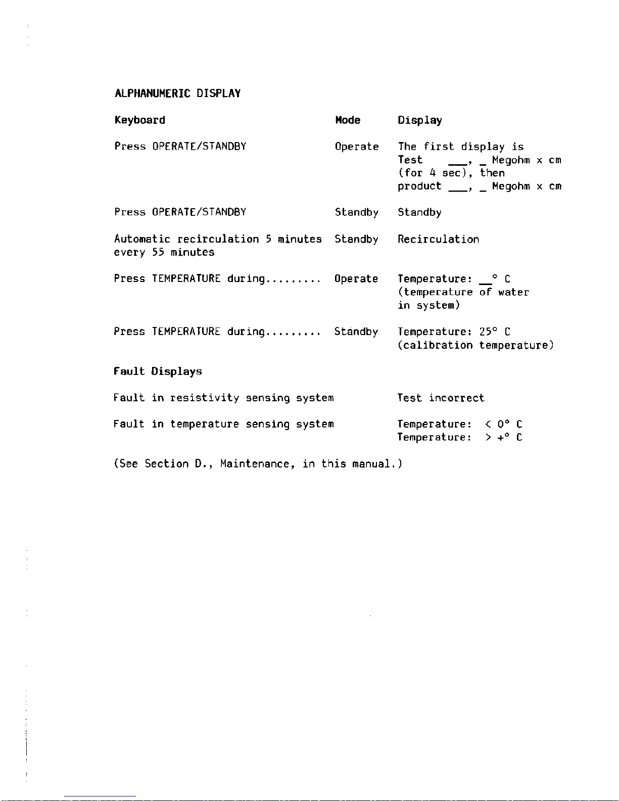
ALPHANUMERIC DISPLAY
Keyboard
Press OPERATE/STANDBY
Mode
Operate
Press OPERATE/STANDBY Standby
Automatic recirculation 5 minutes Standby
every 55 minutes
Press TEMPERATURE during Operate
Press TEMPERATURE during Standby
Fault Displays
Fault in resistivity sensing system
Fault in temperature sensing system
Display
The first display is
Test , _ Megohm x cm
(for 4 sec), then
product , _ Megohm x cm
Standby
Recirculation
Temperature: ° C
(temperature of water
in system)
Temperature: 25° C
(calibration temperature)
Test incorrect
Temperature:
Temperature:
< 0° C
> +° C
(See Section D., Maintenance, in this manual.)
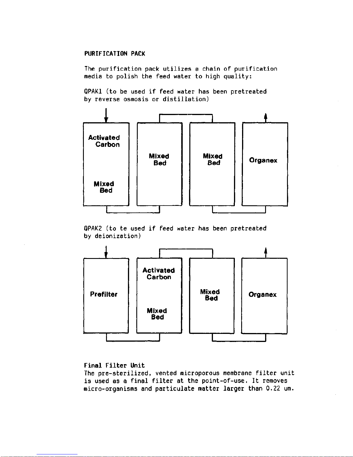
PURIFICATION PACK
The purification pack utilizes a chain
of
purification
media
to
polish
the
feed water
to
high quality:
QPAK1
(to be
used
if
feed water
has
been pretreated
by reverse osmosis
or
distillation)
I
Activated
Carbon
Mixed
Bed
Organex
QPAK2
(to te
used
if
feed water
has
been pretreated
by deionization)
I
Prefilter
I
Activated
Carbon
Mixed
Bed
Final Filter Unit
The pre-sterilized, vented microporous membrane filter unit
is used
as a
final filter
at the
point-of-use.
It
removes
micro-organisms
and
particulate matter larger than
0.22 um.

B.
Installation
1. Unpacking
Unpack the system carefully from its container.
Verify Contents: 1. Milli-Q Plus system
2.
Operation and maintenance manual
3. Power cable
4.
Cover for point-of-use
5. 3 meters of feed water tubing - white, 8 mm O.D.
6. Roll Teflon tape
7.
1/4" male - 8 mm diameter tubing adapter -
feed water
8. 1/2" female to 1/4" female reducing bushing with
stainless steel filter screen
9. 1/4" male - 1/4" hose barb
10.
2 meters tubing, 12 mm O.D.
Purification Pack
The system requires a purification pack which is not included
with the unit. The purification pack must be ordered separately,
The choice of purification pack depends on feed water quality.
Feed Water
Reverse Osmosis or distilled - use CPMQ 004 Rl
Deionized - use CPMQ 004 D2
Pack Contents 1. Purification pack
2.
Millipak final filter unit
B.
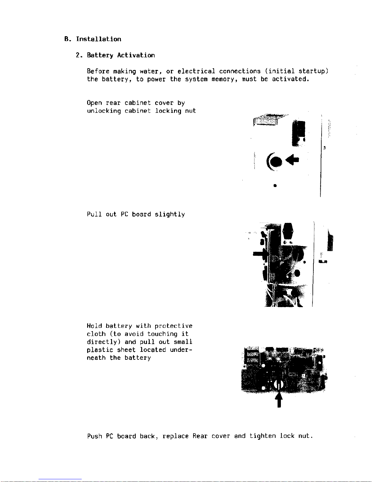
Installation
2.
Battery Activation
Before making water, or electrical connections (initial startup)
the battery, to power the system memory, must be activated.
Open rear cabinet cover by
unlocking cabinet locking nut
Pull out PC board slightly
•Ml
Hold battery with protective
cloth (to avoid touching it
directly) and pull out small
plastic sheet located underneath the battery
Push PC board back, replace Rear cover and tighten lock nut.
Note:
Switch on power immediately after battery activation.
Switch system to ON for a few seconds. This will
initialise the microprocessor and avoid discharging
the battery.
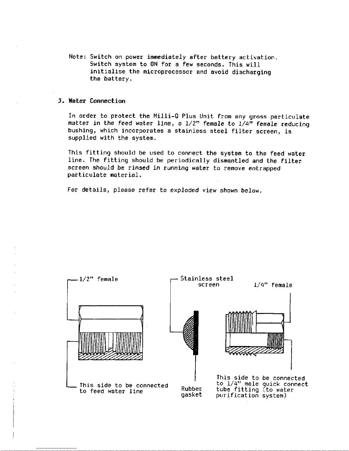
3. Water Connection
In order to protect the Milli-Q Plus Unit from any gross particulate
matter in the feed water line, a 1/2" female to 1/4" female reducing
bushing, which incorporates a stainless steel filter screen, is
supplied with the system.
This fitting should be used to connect the system to the feed water
line.
The fitting should be periodically dismantled and the filter
screen should be rinsed in running water to remove entrapped
particulate material.
For details, please refer to exploded view shown below.
, 1/2" female
Stainless steel
screen
1/4" female
This side to be connected
to feed water line
Rubber
gasket
This side to be connected
to 1/4" male quick connect
tube fitting (to water
purification system)
 Loading...