

Page 1
MiIIe~
November1996
Effective
With Serial
Form:
No.
TM-1571
JJ507797
TECHNICAL
Service
And
MANUAL
Parts
coverjml—SB-124
A
SERVICING
•
Have
qualified
practices.
U
For
help,
Service
414-735-4505
467
WARNING
canbehazardous.
all
service
procedures
persons
call
Factory
Department:
following
performed only
~U~r
Wire
standard
©
S-21E
Feed
Equipment
by
safety
FAX:
14-735-4136
1996
MILLER Electric
Mfg.
Co.
Use
MILLER
150
853)
Use
only genuine
parts.
L................J
Testing Booklet
when
servicing
MILLER
U
Or
write
MILLER
RO.
Box
Appleton,WI54912
this
unit.
replacement
to:
Electric
1079
PRINTEDINUSA
(Part
Mfg.
No.
Co.
USA
Page 2

Page 3
TABLEOFCONTENTS
OM-1571B—3/91
Section
SECTION
SECTION2-SHIPPING
No.
1-SAFETY
1-1.
1-2.
1-3.
General
Safety
Safety
PRECAUTIONS AND
Information And
Alert
Precautions
2-1. Preparation
Symbol And
AND
STORAGE
For
Reshipment
Safety
Signal
SIGNAL
Words
2-2. Storage
SECTION3—SPECIFICATIONS
3-1.
Description
SECTION4-INSTALLATIONORRELOCATION
4-1.
4-2.
4-3.
4-4. Shielding
4-5.
4-6.
4-7.
4-8.
4-9.
4-10.
Location
Drive
Roll
Installation
Welding Gun Connections
Gas
Installation
14-Pin
Welding
Welding
Adjust
Welding
Feeding Welding
Plug
Wire
Wire
The
Cable
Hub
Connection
Installation
Threading
Tension
Connection
Wire
WORDS
Page
No.
1
1
1
2
2
3
3
3
5
5
6
6
7
8
8
8
SECTION
5-OPERATOR
5-1.
5-2.
Power
Wire
Switch
Speed
CONTROLS
Control
SECTION6—SEQUENCEOFOPERATION
6-1.
6-2.
Gas
Metal Arc (GMAW)
Shutting
Down
And
Flux Cored
SECTION7-THEORYOFOPERATION
7-1.
Diagram
Diagram
Theory Of
7-1.
Block
7-2.
Block
Operation
Diagram
Diagram
For
Wire Feeder
For
SpotlBurnback
Arc
(FCAW) Welding
Time
Control
Option
9
9
9
10
10
11
12
Page 4
Section
SECTION8-TROUBLESHOOTING
No.
Page
No.
8-1.
8-2.
8-3.
Diagram
8-4. Motor
Diagram
8-5.
Diagram
SECTION9-COMPONENT
Figure
SECTION
10-1.
10-2.
10-3.
10-4.
10-5.
SECTION
Testing
Circuit
Troubleshooting
Optional
9-1.
10—
Routine
Aligning
ReinstallationOfHub
Brush
Overload
11-ELECTRICAL
Instruments And Information
Board
Handling
8-1.
8-2.
8-3.
MAINTENANCE
Troubleshooting
Board
PCi
Troubleshooting
Board
SpotlBurnback
Troubleshooting
Board PC2
Component
Maintenance
Drive
Roll And
Inspection
Protection
Precautions
Circuit
Testing
Circuit
PCi
Board PC2 Testing
Circuit
IDENTIFICATION
Identification And
Wire
Assembly
And
Replacement
DIAGRAMS
Diagram For
Information
Diagram For
Diagram For
Guide
AND
LOCATION
Location
Wire Feeder
Motor Control
Information
Optional Spot/Burnback
14
14
14
16
17
18
20
22
24
25
26
26
27
27
Diagram
Diagram
Diagram
Diagram
Diagram
SECTION
Table 3-1.
Table 8-1.
Table
Table
11-1.
11-2.
11-3.
11-4.
11-5.
12—
PARTS
Specifications
Troubleshooting
10-1.
Maintenance
11-1.
ListOfCircuit Diagrams
Circuit
JJ507797
Wiring
JJ507797
Circuit
With Serial
Circuit
Effective
Circuit
Effective
Diagram For
Diagram
Diagram For
Diagram
With Serial
Diagram For
With Serial
LIST
LISTOFCHARTS AND
S-21EEffective
And Following
For
S-21EEffective
And Following
No.
Schedule
Motor Control
JJ507797 And Following
For
Optional
No.
JJ507797
Optional Spot/Burnback
No.
JK742029
And
Wiring
With Serial
With
Serial
Board
PCi
SpotlBurnback
Thru
JK742028
And Following
TABLES
Diagrams
No.
29
No.
29
Effective
30
Board PC2
31
Board PC2
32
3
15
25
28
Page 5
SECTION
1-SAFETY
PRECAUTIONS
AND
SIGNAL WORDS
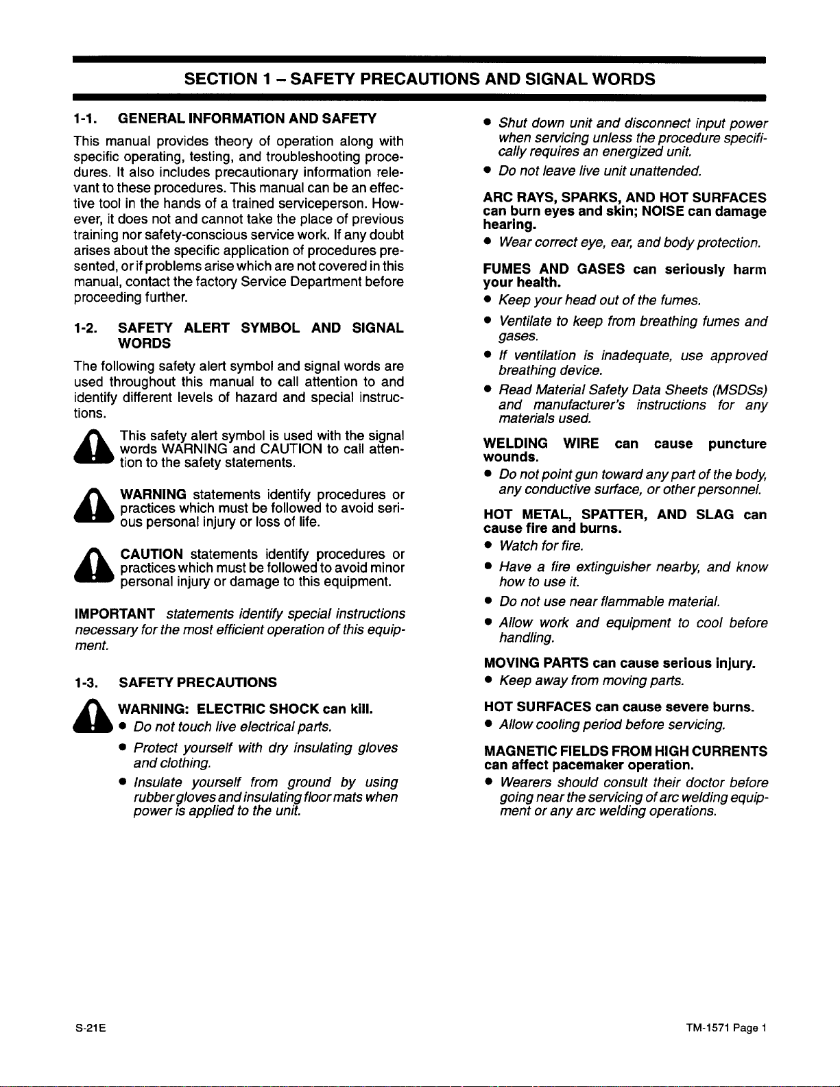
1-1.
This
specific
dures.Italso includes
vanttothese
tive toolinthe
ever,itdoes
training
arises
sented,orif
manual,
proceeding
1-2.
The
used
identify
tions.
A
A
A
IMPORTANT
GENERAL
manual
about
following safety alert
throughout
provides
operating,
procedures.
handsofa
not
nor
safety-conscious service
the
problems
contact
further.
SAFETY
WORDS
different
This safety alert
words
WARNING and
tionto
the
WARNING statements identify
practices which
ous personal injury
CAUTION
practices which
personal injuryordamagetothis
statements identify special
necessary
for
the
INFORMATION
testing, and
and
cannot
specific
arise
the
factory
ALERT
this
levels of
safety
statements identify procedures
most efficient
ment.
1-3.
SAFETY
PRECAUTIONS
AND SAFETY
theoryofoperation
troubleshooting
precautionary information
This
manual
trained
application
which
symbol
manual to
hazard
symbolisused
statements.
mustbefollowedtoavoid
mustbefollowedtoavoid
serviceperson.
take
the
work.Ifany
of procedures
are
not
Service Department
SYMBOL AND
and signal
call
and
CAUTIONtocall
or loss of
along
can
be an
placeofprevious
covered
SIGNAL
words
attention
special
with
the
procedures
life.
equipment.
instructions
operationofthis
with
proce-
rele-
effec
How-
doubt
pre
in this
before
are
to and
instruc
signal
atten
or
seri
or
minor
equip
•
Shut
down
unit
and
disconnect
when
servicing
cally
requiresanenergized
•
Do
not
leave
-
-
ARC
RAYS,
can
burn eyes
hearing.
•
Wear
FUMES
your
health.
•
Keep
•
Ventilate to
correct
AND
your
unless
live
SPARKS,
and
eye,
GASES can
the
unit
unattended.
AND HOT
skin; NOISE
ear,
and body
head outofthe
keep
from
breathing
input
procedure
unit.
SURFACES
can
damage
protection.
seriously
fumes.
fumes
power
specifi
harm
and
-
gases.
•Ifventilationisinadequate,
breathing
•
-
Read Material
and
materials
-
WELDING
wounds.
•
Do
any
-
HOT
cause
•
Watch
•
Haveafire
howtouse
•
Do
•
-
Allow
device.
Safety
manufacturer’s
used.
WIRE
not
point
gun towardany
conductive
METAL,
fire
and
for
surface,orother
SPATrER,
burns.
fire.
extinguisher
it.
not
use
near
flammable
work
and
Data
instructions
can
equipmenttocool
use
Sheets
cause
part of
AND
nearby
material.
approved
(MSDSs)
for
any
puncture
the
body,
personnel.
SLAG
and
can
know
before
handling.
MOVING
•
Keep
PARTS
away
can
from
cause
moving
serious
parts.
injury.
A
5-21E
W
ARNING: ELECTRIC
S
Do
not
touch
live
•
Protect
and
•
Insulate
rubber9loves
power is
yourself
clothing.
yourself
and
appliedtothe
SHOCK
electrical
with
dry
from
groundbyusing
insulating
unit.
can kill.
parts.
insulating
floormats
gloves
when
HOT
SURFACES
•
Allow
cooling
MAGNETIC
can
affect
pacemaker
•
Wearers
going near
mentorany
can
period
FIELDS
should
consult
the
servicingofarc
arc
welding
cause
before
FROM
HIGH CURRENTS
operation.
their
operations.
severe
burns.
servicing.
doctor
welding
TM-1571
before
equip
Page
1
-
Page 6
SECTION2-SHIPPING
AND
STORAGE
PREPARATION
WARNING:
•
Do
not
A
•
Shut
source,
ing
touch
down wire
and
lockout/tagging
preparing unit
Lockout/tagging
sistofdisconnecting
for
welding
line
disconnect switch
ing
fuses
from
tagging circuit breaker or
device.
(—)
erators.
1.
Disconnect
feeder.
2.
Disconnect
3.
Disconnect and remove
devices.
4.
Disconnect
ble)
5.
Disconnect gun
6.
Secure
wire
7.
Tape
8.
Securely
around
if
available.
IMPORTANT:
Not
onlydocosts increase
more
subjecttolossordamage
9.
If
sending
factory
Department.
Stop
battery
hoses from
spoolorreel
cable
interconnecting
weld
shielding
welding
plastic
tie
sidesofunit.
Do
not
unittofactory,
Service
FOR
RESHIPMENT
ELECTRIC
live
disconnect
SHOCK
electrical
feeder
and
input
can
parts.
welding
power
procedures
for
shipping.
procedures
power
source
fuse
box,
engine, and
from
cable
gas
wire
feeder.
from
wire
wiretospool/reel,
from
around
and/or tape cardboard over
top
Use
ship without
dramatically
forwire
interconnecting
consistofpadlocking
in open
or shutting
other
disconnect
batteryonwelding
cord
from drive
any
remote
(and
feeder.
wire
feeder.
and
sidesofunit.
original
feedercon
position,
off
disconnecting
from
rearofwire
assembly.
controls
waterifapplica
and
shipping carton
a cardboard
but
cord,
the
withoutacarton.
ship
unitasdirected
DepartmentorTransportation
kill.
power
employ
before
and
remov-
and rednegative
gen
remove
top
and
carton.
unit
or
by
is
STORAGE
WARNING:
•
A
-
Do
•
Shut
source,
ing
ELECTRIC
not
touch
live
electrical
down
wire
feeder
and
disconnectinput power
lockout/tagging
procedures
SHOCK
parts.
and
can
kill.
welding
employ
before
power
-
storing
unit.
-
-
-
10.
11.
12.
13.
Lockout/tagging
sistofdisconnecting
for
welding
line
disconnect switch
ing
fuses
tagging circuit
device. Stop
(—)
battery
erators.
1.
Disconnect
feeder.
2.
Disconnect weld
3.
Disconnect and remove
devices.
4.
Disconnect
ble)
hoses
5.
Disconnect gun
6.
Secure
wire
spoolorreel
7.
Clean outside of
8.
Remove
9.
Using
Reinstall wrapper.
Selectastorage
unittowide
corrosive
Carry
Cover
power
from
cable
interconnecting
shielding
from
welding
wrapper.
dry
compressed
temperature
vapors.
unit
to storage
unit
with
procedures
source consistofpadlocking
fuse box,
breakerorother
engine, and
from
cable
gas
wire
feeder.
from
wire
wiretospool/reel,
from
unit.
location that
location.
plastic
forwirefeedercon
interconnecting
in open
or shutting
disconnect negative
batteryonwelding
cord
from drive
any
remote
(and
feeder.
wire
feeder.
air,
clean
least
variation,
or suitable
cord,
position,
off and
disconnecting
from
rearofwire
assembly.
controls
waterifapplica-
and remove
inside of
subjects
dust,
tarp.
and
remov-
red-
gen
unit.
the
dirt,
and
-
-
or
TM-1571
Page
2
5-21E
Page 7
SECTION3-SPECIFICATIONS
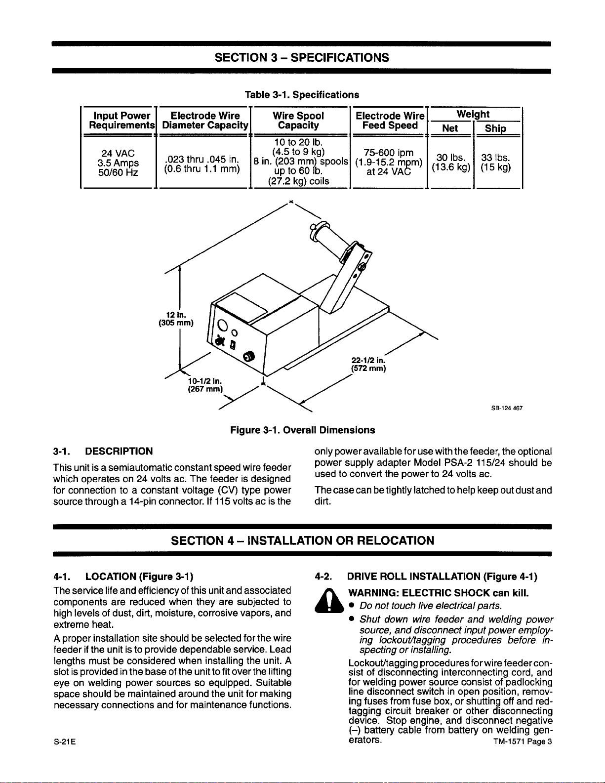
Input
Power
Requirements
24
VAC
3.5
Amps
50/60
Hz
Electrode
Diameter
.O23thru
(0.6 thru
10-112
(267
Wire
Capacity
.045
in.
1.1
mm)
In.
mm)
Table 3-1.
Wire
Capacity
10to20
(4.5 to9kg)
8
in.
(203mm)
upto60
(27.2
Specifications
Spool
lb.
spools
lb.
kg)_coils
Electrode
(1.9-15.2
22-1(2
(572
Wire
Feed Speed
75-600 ipm
mom)
at24VA~
in.
mm)
Net
30
(13.6
Weight
lbs.
kg)
Ship
33
lbs.
(15 kg)
3-1. DESCRIPTION
This
unitisa
which
for
connection toaconstant
source
4-1.
The
service
components
high
levels of
extreme
A
proper installation
feederifthe
lengths
slotisprovided in
eyeonwelding
space
necessary
S-21E
semiautomatic
operates
througha14-pin
LOCATION
heat.
mustbeconsidered
shouldbemaintained
on 24
volts
(Figure 3-1)
life
and
efficiencyofthis unit
are
reduced
dust,
dirt, moisture,
site shouldbeselected
unitisto provide
the
baseofthe
power
connections
Figure
constant speed wire feeder
ac.
The
feederisdesigned
voltage (CV)
connector.If115
volts acisthe
3-1. Overall Dimensions
only
power supply
used
type
power
The
dirt.
SECTION4-INSTALLATION OR
4-2.
and
associated
when
they
are
subjected to
corrosive
dependable
when
installing
unittofit
sourcessoequipped. Suitable
around
and
for
maintenance
the
vapors, and
for
the
service.
the
over
the
unit
for
making
functions.
wire
Lead
unit.
lifting
A
A
power
available
to convert
case
canbetightly
for
adapter
the
powerto24
use
Model
latched to
RELOCATION
DRIVE
WARNING: ELECTRIC
•
•
Lockout/tagging
sistofdisconnecting
for
line
ing
tagging
device.
(—)
erators.
ROLL
INSTALLATION (Figure 4-1)
Do
not
touch
live
Shut
down
wire
source,
ing
and
disconnect
lockout/tagging
spectingorinstalling.
welding
disconnect switch
fuses
battery
power
from
circuit
Stop
cable
fuse
breakerorother
engine, and
SB-124
467
with
the
feeder,
PSA-2
volts
help
SHOCK
electrical
feeder and
input
procedures
procedures
source consistofpadlocking
box,
from
for
interconnecting
in open
or shutting
disconnect negative
batteryonwelding
the
optional
115/24 should
ac.
keep
out
dust
can kill.
parts.
welding
power
power
employ
beforein-
wire feeder
cord,
position,
remov-
off
and
disconnecting
TM-1571
Page
be
and
con
and
red-
gen
-
-
-
3
Page 8
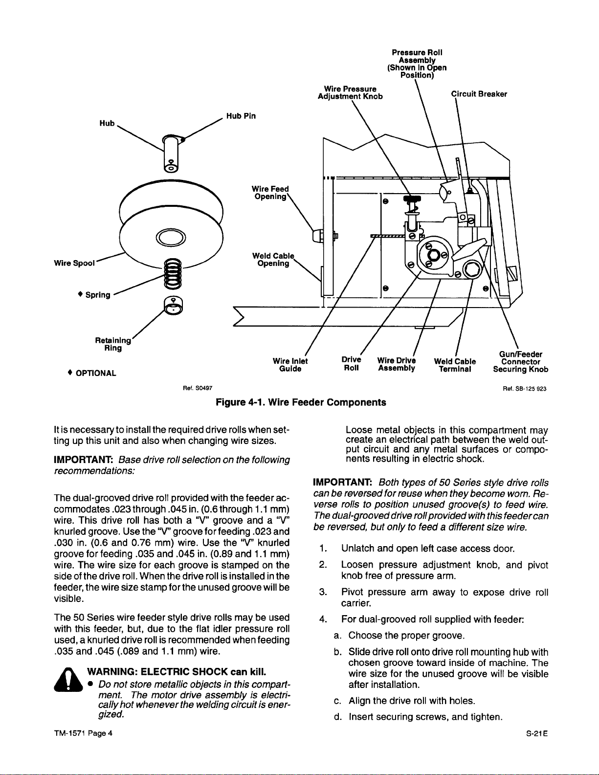
Wire
•
Spring
Hub
Pressure
(ShownInOpen
9
Roll
Assembly
PosItion)
Retaining
Ring
•
OPTIONAL
Itisnecessarytoinstall
tingupthis unit
IMPORTANT:
Base drive
and
the
also
recommendations:
The
dual-grooved drive
commodates
wire.
This
knurled
.030
in.
groove
wire.
The
sideofthe
feeder,
visible.
The50Series wire feeder
with
this feeder,
used,aknurled
.035
and
A
.023
drive
groove.
(0.6 and
for
feeding
wire
drive
the
wire
.045
(.089
W
ARNING:
Do
not
ment. The
cally
Use
size
roll.
size
drive
hot
roll
through
roll
has
the “V”
0.76
mm)
.035
and
for
each
When
stamp
but,
due to
roll is
and
ELECTRIC
store metallic
motor
whenever
gized.
TM-1571
Page
4
Ret.
50497
Figure
required
when
roll
provided
.045
both
groove
the
for
style
recommended
1.1
drive
changing
selectiononthe
with
in.
(0.6 through
a
“‘I”
groove
for
wire.
Use
.045
in.
(0.89
grooveisstampedonthe
drive
roll is
the
unused
drive
rolls
the flat
mm)
idler pressure
wire.
SHOCK
4-1.
rolls
when
wire
the
feederac-
and
feeding
the
“V”
and
installedinthe
groove
maybeused
when
can
objectsinthis
drive
assemblyiselectri
the
welding
circuitisener
Wire
set
sizes.
following
1.1
mm)
a
“‘I”
.023
and
knurled
1.1
mm)
will
be
roll
feeding
kill.
compart
Feeder
-
IMPORTANT:
can
verse
The
be
1.
2.
3.
4.
-
-
-
Components
Loose
createanelectrical
put
nents
metal
circuit and
resulting in
Both
be reversed
for
rollstoposition
dual-grooved
reversed,
a.
b.
c.
d.
but
Unlatch
Loosen
knob
Pivot
carrier.
For
and
pressure
free of
pressure
dual-grooved
Choose
Slide
drive
chosen
wire
size
after
installation.
Align
the
Insert
securing
the
groove
objects
path
any
metal
electric
typesof50
reuse
when
unused
drive
roll
pro
onlytofeed a
open
left
case
adjustment
pressure
proper
roll onto
for
the
drive
arm.
arm
away
roll
supplied
groove.
drive
toward
unused
roll
with
screws, and tighten.
GunlFeeder
connector
Securing
Ref.
in this
compartment
between
surfacesorcompo-
shock.
Series
they
the
style
become
groove(s)tofeed
vided
with
this
feedercan
different
inside of machine.
holes.
size
access
to expose
roll
groove
door.
knob,
with
feeder:
mounting hub with
willbevisible
Knob
SB-125
923
may
weld
out
drive
rolls
worn.Re-
wire.
wire.
and
pivot
drive
roll
The
5-21E
-
Page 9
5.
For50Series
a.
Slide
b.
Align
c.
Insert
6.
For50Series
a.
Align holesonpair of split
b.
Insert
c.
Slide
d.
Align
e.
Insert
IMPORTANT:
the drive
set
becomes
7.
4-3.
A
roll
and
should
necessary,
Close
WELDING
And
WARNING:
•
Do
•
Shut
mounting
and
5-1)
source,
ing
ingonfeeder.
Lockout/tagging
sistofdisconnecting
for
welding
line
disconnect switch
ing
fuses
tagging circuit
device.
(—)
battery
erators.
IMPORTANT:
stallationofa
gas
line.
Remove snap-in
style
one-piece
drive
roll
onto
drive
drive
roll
with
holes.
securing
securing
drive
drive
securing
Horizontal
not
not
down
lockout/tagging
Stop
A
gun
screws, and tighten.
style
screw.
rolls
onto
rolls
with
screws, and tighten.
hub
require
secure
GUN
touch
readjustment.Ifreadjustment
see
Section 10-2.
left
CONNECTIONS
ELECTRIC
live
wire
and
disconnect
procedures
power
from
fuse box,
breakerorother
engine, and
cable
from
hole
ispro
requiring an
split
drive
holes.
alignmentofthe drive
with
case
electrical
feeder
procedures
interconnecting
source consistofpadlocking
videdinthe
blank
drive
rolls:
roll
drive
rolls:
drive
roll
the
wire
access
SHOCK
mounting
rolls.
mounting
guideisfactory
hub.
door.
(Figures
can kill.
parts.
and
welding
input
power
employ
before
for
wire feeder
cord,
in open
batteryonwelding
position,
or shutting
disconnecting
disconnect
remov-
off
and red-
negative
nameplate
opening
before
foranexternal
installation.
hub.
roll
on
4-1
power
work
con
and
gen
form-
B.
Connect
front
into
clockwise.
4-4.
A
A.
-
Chain
-
prevent
the
-
secure gas
B.
1.
-
IMPORTANT:
leaks.Donot
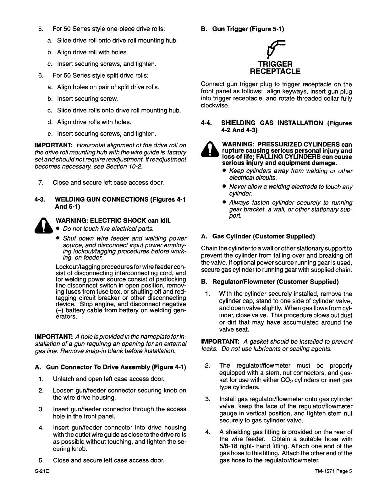
Gun
Trigger (Figure 5-1)
‘9=
TRIGGER
RECEPTACLE
gun
trigger plugtotrigger receptacleonthe
panelasfollows:
trigger
receptacle,
SHIELDING
4-2
And
4-3)
WARNING:
rupture
lossoflife;
serious
•
causing serious
injury
Keep
cylinders
electrical circuits.
•
Never
allow
cylinder.
•
Always fasten
gear
bracket,awall,orother
port.
Gas
Cylinder (Customer
the
cylindertoa
the
cylinder
valve.Ifoptional
cylinder
Regulator/Flowmeter
With
the
cylinder
cylinder
and
inder,
or
valve
open
dirt
cap,
valve
close
that
seat.
A
use
align
and
GAS
PRESSURIZED
FALLING
and
a welding
wall or
from
power
to running
stand
slightly.
valve.
may
have
gasket shouldbeinstalledtoprevent
lubricantsorsealing
keyways,
rotate
threaded
INSTALLATION
CYLINDERS can
personal
CYLINDERS
equipment
away
from
electrodetotouch
cylinder
falling
source
(Customer
securely
to one
This procedure
securelytorunning
Supplied)
other
stationary
over
running
gear
with
installed,
sideofcylinder
When
gas
accumulated
insert
gun
plug
collar
fully
(Figures
injury
and
can
cause
damage.
weldingorother
any
stationary
and
breaking
gear is
supplied
Supplied)
remove
flows
blows
support
used,
chain.
valve,
from
out
around
sup-
to
off
the
cyl
dust
the
agents.
-
A.
1.
2.
3.
4.
5.
S-21E
Gun
ConnectorToDrive
Unlatch and
Loosen
the
wire
Insert
holeinthe
Insert
with
the
as
possible
curing
Close and
open
gun/feeder
drive
housing.
gun/feeder connector
front
panel.
gun/feeder
outlet
wire
without touching,
knob.
secure
Assembly
left
case
access
connector securing
through
connector
guideasclosetothe
left
case
access
into
and
tighten
(Figure 4-1)
door.
drive
door.
knob
the
housing
drive
on
access
rolls
these-
2.
The
regulator/flowmeter
equipped withastem,
ket
for
use
type
cylinders.
3.
Install
gas
regulator/flowmeter onto
valve;
securelytogas
4.
A
the
keep
gaugeinvertical
shielding
wire
feeder.
5/8-18
gas
gas
right- hand
hosetothis
hosetothe
must
nut
connectors,
with
either
CO
2
cylindersorinert
the
faceofthe
position,
cylinder
gas fittingisprovidedonthe
Obtainasuitable
fitting.
fitting.
regulator/flowmeter.
and
valve.
Attach
Attach the
be
gas
regulator/flowmeter
tighten
one end of
other
TM-1571
properly
and
cylinder
stem
rear of
hose
end of
Page
gas
gas
nut
with
the
the
-
5
Page 10
Flow
Adjustment
CO
2
Washer
CO2
Installation
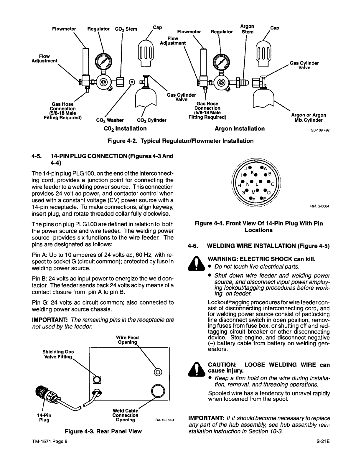
Figure
CO2
cylinder
4-2. Typical
Argon
RegulatorlFlowmeter
Installation
Installation
Gas
cylinder
Valve
ArgonorArgon
Mix
cylinder
SB-109
492
4-5.
The
ing
wire
provides24voltacpower,
used
14-pin
insert
The
the
source
pins
PinA:Upto10
specttosocket
welding
PinB:24
tactor.
contact closure
PinG:24
welding
IMPORTANT:
not
14-PIN
4-4)
14-pin
cord,
feedertoa
withaconstant
receptacle.Tomake
plug,
pinsonplug
power
are
The
usedbythe
Shielding
valve
PLUG CONNECTION
plug
PLG1
providesajunction
welding
and
rotate
PLG
source
provides
designated as
power
volts ac
volts ac
power
and
six
amperesof24
G (circuit
source.
input
feeder
sends
from pin Atopin
circuit common;
source
The
remaining
feeder.
Gas
Fitting,
00,onthe
power
voltage
threaded
100
wire
functionstothe
follows:
common);
powertoenergize
back24volts ac by
chassis.
(Figures
end of
the
interconnect
point
for
connecting
source.
and
contactor
(CV)
connections,
are
definedinrelationtoboth
feeder.
volts
pinsinthe
This
control when
power
source
align
collar
fully
The
welding
wire
feeder.
ac,60Hz,
protected by
the
B.
also connected
receptacle are
Wire
Feed
connection
clockwise.
weld
meansofa
4-3
And
the
with
a
keyway,
power
The
withre-
fuse
in
con
to
-
Ref.
S-0004
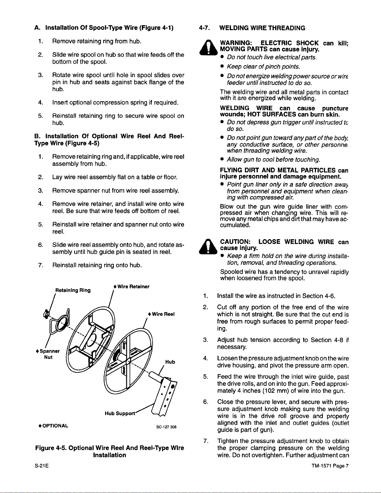
Figure
4-6.
A
-
4-4. Front
WELDING
WARNING: ELECTRIC
•
Do
not
•
Shut
source,
ing
lockout/tagging
ViewOf14-Pin
Locations
WIRE
INSTALLATION
touch
live
down
wire
and
disconnect
electrical
feeder and
procedures
Plug
SHOCK
parts.
input
With
Pin
(Figure
can kill.
welding
4-5)
power
poweremploy
before
work
-
-
ingonfeeder.
A
Lockout/tagging
sistofdisconnecting
for
welding
line
disconnect
ing
fuses
tagging
device.
(—)
erators.
CAUTION: LOOSE
cause
•
Spooled wire
when
circuit
Stop
battery cable
Injury.
Keepafirm
tion,
removal,
loosened
procedures
power
source consistofpadlocking
switch
from
fuse
box,
breakerorother
engine, and
from batteryonwelding
holdonthe
and
hasatendencytounravel
from
forwire
interconnecting
in open
or shutting
disconnect
WELDING
wire
threading
the
spool.
feeder
cord,
position,
during
remov-
off and
disconnecting
negative
WIRE can
installa
operations.
rapidly
con
and
red-
gen
-
-
-
14-Pin
Plug
TM-1571
Page
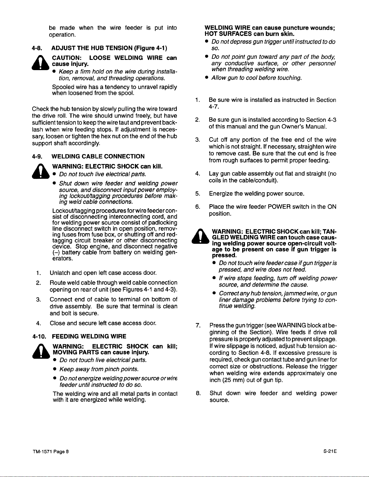
Figure
6
4-3.
Rear
Weld
Cable
Connection
Opening
Panel
View
SA-125
924
IMPORTANT:
any
part of
If
it should become
the
hub
assembly
stallation instructioninSection
necessarytoreplace
see
hub
assembly
10-3.
rein
5-21E
-
Page 11
A.
InstallationOfSpool-Type
1.
Remove
2.
Slide
bottomofthe
3.
Rotate
pininhub and
hub.
4.
Insert optional
5.
Reinstall retaining
hub.
B.
InstallationOfOptional
Type
Wire
1.
Remove
assembly
2.
Lay
3.
Remove
4.
Remove wire
reel.Besure
5.
Reinstall
reel.
6.
Slide
sembly
7.
Reinstall retaining
retaining
wire
spoolonhubsothat
spool.
wire
spool
seats
compression springifrequired.
(Figure 4-5)
retaining
from hub.
wire
reel
assembly
spanner
retainer,
that
wire
retainer and
wire
reel
assembly
until
hub
Wire
ring
from
hub.
until
hole
in spool
against back
ringtosecure
Wire
ring
and,ifapplicable,
flat
on a
nut
from
wire
and
install
wire
feeds
spanner
onto
guide
pin is
ring
onto
hub.
•Wlre
Retainer
(Figure 4-1)
wire
feeds
slides
flangeofthe
wire
spool
Reel
And
tableorfloor.
reel
assembly.
wire onto wire
off
bottomofreel.
nut
onto wire
hub,
and
rotateas-
seated in
reel.
off
wire
the
over
on
Reel-
reel
4-7.
A
A
WELDING
WARNING:
MOVING
•
Do
•
Keep
•
Do
feeder
The welding
withitare
WELDING
Wounds;
•
Do
do
•
Do
any
WIRE
ELECTRIC
PARTS
not
touch
clearofpinch
not
energize welding
until
instructedtodo
wire
energized
WIRE can
HOT
not
depress
so.
not
point
gun towardany
conductive
when threading
•
Allow
guntocool before
FLYING
injure personnel
•
Blow
pressed
move
cumulated.
CAUTION:
cause
•
Spooled wire
when
1.Install
DIRT
Point
gun
from
personnel
ing with
compressed
out the
air
when
any
metal
Injury.
Keepafirm
tion,
removal,
loosened
the
wireasinstructedinSection 4-6.
AND
liner onlyina
gun
LOOSE
hasatendencytounravel
THREADING
SHOCK
can
live
electrical
cause
injury.
parts.
points.
power
sourceorwirE
so.
and
all
metal
partsincontaci
while
welding.
cause puncture
SURFACES
gun
can
trigger
burn skin.
untll
part of
surface,orother
welding
wire.
touching.
METAL PARTICLES can
and
damage equipment.
safe direction
and
equipment when
air.
wire
9uide
liner
changing
chips
and
holdonthe wire
and
threading
from
the
wire.
dirt
that
WELDING
during
operations.
spool.
may
can
kill;
instructed
the
body
personne.
awaj~
clean~
with
com
This
willre-
haveac-
WIRE
can
installa
rapidly
tc
-
-
•
Spanner
Nut
•
OPTIONAL
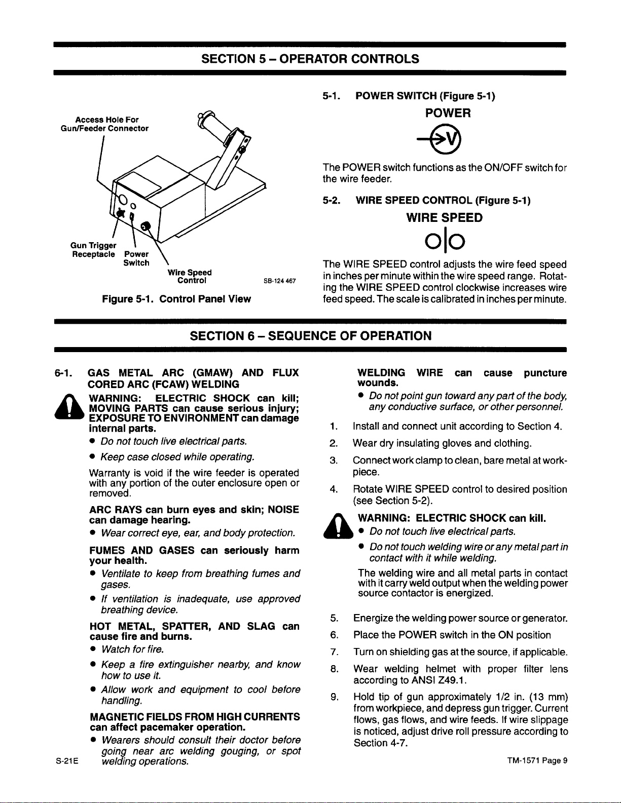
Figure
S-21E
4-5.
Optional Wire
Reel
Installation
And
Reel-Type
SC-127
306
Wire
2.
Cut
off
any
portionofthe
whichisnot straight.Besure
free
from
rough
surfacestopermit
ing.
3.
Adjust
necessary.
4.
Loosen
drive
5.
Feed
the
mately4inches
6.
Close
sure
wireisin
aligned with
guideispart of
7.
Tighten
the
wire.Donot
hub
tension according to Section
the
pressure
housing,
the
drive
the
adjustment knob
proper
and
wire
through
rolls,
andoninto
(102
pressure
the
drive
the
gun).
the
pressure
clamping
overtighten. Further
free
endofthe
that
the
cut
proper
adjustment knobonthe
pivot
the
pressure
the
inlet
the
gun.
mm)ofwire
lever,
and
secure
making
roll
groove
inlet
and
outlet
adjustment knobtoobtain
pressureonthe
arm open.
wire
guide, past
Feed
into
the
with
sure
the
and
guides
adjustment
TM-1571
wire
end
is
feed
4-8
wire
approxi
gun.
pres
welding
properly
(outlet
welding
can
Page
-
if
-
-
7
Page 12
be
operation.
4-8.
A
Check
the
sufficient
lash
sary,
support
4-9.
A
4-10.
A
ADJUST
CAUTION: LOOSE
:ause
Spooled
when
the
drive
when
loosen or
shaft
WELDING
WARNING: ELECTRIC
•
•
Lockout/tagging
sistofdisconnecting
for
line
ing
tagging
device.
(—)
erators.
1.
Unlatch and
2.
Route
openingonrearofunit
3.
Connect
drive
and
4.
Close and
FEEDING WELDING
WARNING: ELECTRIC
MOVING
•
•
•
The
withitare
made
Keepafirm
tion,
hub
roll.
tensiontokeep the
Do
Shut
source,
ing
ing
Do
Keep
Do
feeder
when
THE
Injury.
removal,
wire
loosened from
tensionbyslowly
The
wire
feeding
tighten
accordingly.
not
touch
down
lockout/tagging
weld
welding
disconnect switchinopen
fuses
from
circuit
Stop
battery
weld
end of
assembly.Besure
boltissecure.
secure
PARTS
not
touch
away
not
energize
until
welding
the
wire
HUB
TENSION
WELDING
holdonthe wire
and
threading
hasatendencytounravel
the
wire
should
the
CABLE
live
wire
and
disconnect
cable
power
fuse box,orshutting
breakerorother
engine,
cable
open
cable
cabletoterminalonbottom
live
from
instructedtodo
wire
energized
unwind
wire
stops.Ifadjustmentisneces
hex
nutonthe
CONNECTION
SHOCK
electrical
feeder and
procedures
connections.
procedures
interconnecting
source
and
from
batteryonwelding
left
case
through weld
(see
left
case
WIRE
can
cause
electrical
pinch
welding
and
all
while
feederisput
(Figure 4-1)
WIRE can
during
operations.
spool.
pulling
the
wire
freely,
taut and
consistofpadlocking
that
points.
metal
prevent
end of
can
parts.
welding
input
power
before
forwire
disconnect negative
access
Figures
access
SHOCK
powersourceorwirE
welding.
feedercon
position,
off
disconnecting
door.
cable
connection
4-1
terminalisclean
door.
Injury.
parts.
so.
partsincontaci
into
installa
rapidly
toward
but have
back
the
hub
kill.
power
employ
mak
cord,
and
remov
and
red-
gen
and
4-3).
can kill;
of
WELDING
HOT
•
Do
so.
•
Do
any
-
-
-
-
-
-
-
A
-
when threading
•
Allow
1.
Be
4-7.
2.
Be
of
this
3.
Cut
whichisnot straight.Ifnecessary,
to remove cast.Besure
from
4.
Lay
coilsinthe
5.
Energize the
6.
Place
position.
WARNING: ELECTRIC
GLED
ing Welding power
agetobe
pressed.
•
•Ifwire
•
7.
Press
ginningofthe Section).
pressureisproperly
If
wire
cordingtoSection
required,
correct
when
inch
8.
Shut
source.
WIRE
can
cause
SURFACES
not
depress
not
point
conductive
guntocool
sure
wireisinstalledasinstructedinSection
sure
gunisinstalled
manual
off
any
rough
gun
cable
the
WELDING
Do
not
pressed,
source,
Correctanyhub
liner
damage
tinue
welding.
the
gun
slippageisnoticed,
check
sizeorobstructions.
welding
(25
mm)
down
can
gun
gun
toward
surface,orother personnel
welding
before
and
the
portionofthe
surfacestopermit proper
assembly
cable/conduit).
welding
wire
feeder POWER switchinthe
WIRE can
presentoncaseifgun
touch
wire
and
wire does
stops
feeding,
and
determine
tension,
problems
trigger
adjustedtoprevent
4-8.Ifexcessive
gun
contact
wire extends
outofgun tip.
wire
feeder
puncture
burn skin.
trigger until
according
gun
that
out flat
power
source
feeder
(see
Wire feedsifdrive
instructedtodo
any
part of
wire.
touching.
to Section
Owner’s
free
source.
SHOCK
caseifgun
not
tum
the
jammed
before
WARNING blockatbe
adjust
tube
Release
approximately
and
Manual.
end of
straighten
the
cut
and
can kill;
touch
open-circuit
feed.
off
welding
cause.
tryingtocon-
hub
and gun
welding
endisfree
feeding.
straight
case
wire,orgun
tensionacpressure
Wounds;
the
body
4-3
the
wire
wire
(no
ON
TAN
caus-
volt
trigger
slippage.
the
trigger
power
roll
liner
for
trigger
one
power
is
is
is
-
-
-
TM-1571 Page
8
S-21E
Page 13
SECTION5-OPERATOR
CONTROLS
Access
Gun/Feeder
Gun
Trigger
Receptacle
6-1.
A
GAS
CORED
WARNING: ELECTRIC
MOVING
EXPOSURETOENVIRONMENT
internal parts.
•
•
Warrantyisvoidifthe
with
removed.
ARC
can
•
FUMES
your
•
•Ifventilationisinadequate,
HOT
cause
•
•
•
MAGNETIC
can
•
5-21
E
Hole
For
Connector
Wire
Figure
Do
Keep
Wear
5-1.
Control
METAL
ARC
not
case
any
portionofthe
RAYS
damage hearing.
correct
AND
health.
ARC
(FCAW)
PARTS
touch
live
closed
can
eye,
GASES can
burn
Ventilatetokeep
gases.
breathing
Watch
Keepafire
howtouse
Allow
device.
METAL,
fire
and
for
fire.
work
SPATrER,
burns.
extinguisher
it.
and
handling.
FIELDS
affect
pacemaker operation.
Wearers
going
welding
should
near
arc
operations.
Speed
Control
Panel
View
SECTION
(GMAW)
WELDING
can
cause
electrical
while operating.
wire
outer
eyes
ear,
and body
from
breathing
equipmenttocool
FROM
consult
welding
AND
SHOCK
serious
can
parts.
feederisoperated
enclosure open
and
skin; NOISE
seriously
use
AND
nearby
HIGH
CURRENTS
their
doctor
gouging,orspot
5-1.
The
the
5-2. WIRE SPEED
The
88-124
467
in
ing
feed
6—
SEQUENCEOFOPERATION
FLUX
can kill;
injury;
damage
POWER
POWER switch
wire
feeder.
WIRE
SPEED
inches per
the WIRE
speed.
minute
The
WELDING
Wounds.
•
Do
any
1.
Install
2.
Wear
dry
3.
Connect
SPEED
not
conductive
and
piece.
or
protection.
harm
4.
A
Rotate
(see
WIRE
Section
WARNING:
•
Do
not
•
Do
not
contact
fumes
and
The
welding
withitcarry
approved
SLAG
and
know
can
source
5.
Energize
6.
Place
the
7.
Turnonshielding
8.
Wear
welding
accordingtoANSI Z49.1.
before
before
9.
Hold
from
flows,
is
Section 4-7.
tip
workpiece,
gas
noticed,
SWITCH
(Figure 5-1)
POWER
functions as
CONTROL
the
ON/OFF switch
(Figure 5-1)
WIRE SPEED
ojo
control
scaleiscalibratedininches per
point
connect
insulating gloves
work
touch
touch welding
withitwhile
weld
contactorisenergized.
the
welding
POWER switchintheONposition
of gun
flows,
adjust drive
adjusts
within
the
control
WIRE can
gun
wire
clockwise
toward
surface,orother
unit
according
clamptoclean,
SPEED
controltodesired
5-2).
ELECTRIC
live
SHOCK
electrical
wireorany
welding.
wire
and all
metal
output when
power
gasatthe
helmet with
approximately
and
depress
and
wire
feeds.Ifwire
roll
pressure
the
wire
feed
speed
range.
increases
minute.
cause
any
part of
puncture
the
personnel.
to Section
and
clothing.
bare metalatwork-
position
can kill.
parts.
metal
partsincontact
the
welding
sourceorgenerator.
source,ifapplicable.
proper filter lens
1/2 in.
gun
(13
trigger.
Current
slippage
according
TM-1571
for
speed
Rotat
wire
body
4.
part
in
power
mm)
to
Page
9
-
Page 14
WARNING: ELECTRIC
A
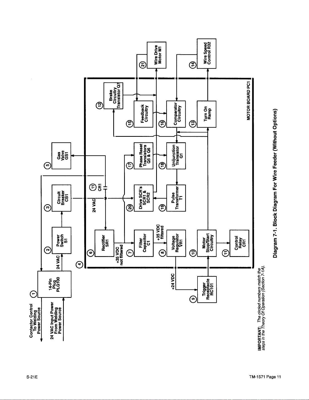
7-1.
IMPORTANT:
writteninsteps
grams
A.
TANGLED
causing
voltagetobe
pressed.
•
Do
pressed
•Ifwire
source,
•
Correctanyhub
liner
continue
THEORYOFOPERATION
7-1
and
Wire
Feeder
The
1.
2.
3.
4.
5.
6.
7.
8.
9.
14-pin
connecting cord
from
the
tactor
POWER switch51provides
volts ac
Circuit
for
the
Motor
drive
R32.
PCi
ing
power
CR1.
Gas
valve
weld
cycle.
Integrated
input
CapacitorClprovides
Voltage regulator
put
voltageto24
PCi
and
Trigger receptacle
put signaltothe
WELDING
welding
presentoncaseifgun
not
touch
and
stops
and
damage
welding.
The
following
which
match
7-2.
Without
plug PLG100onthe
welding
controltothe
input
powertothe
breaker
wire
Board
motorMlas
powertoa
CB1
feeder.
PCi
also
controls
source
051
rectifier
trigger
provides
SHOCK
WIRE can
power
wire
wire does
feeding,
determine
tension,jammed
problems
source
feeder
not
turn
the
caseifgun
feed.
off
welding
cause.
before
SECTION7-THEORYOFOPERATION
TheoryOfOperation
the
circled
Options
provides24volts ac
power
source
welding
provides
regulates
setbyWIRE
gas
contactor
shielding
SRi
converts
rectified35volts
filtering
VR1
reduces the35volts dcin-
volts dc
receptacle
RC101provides
motor
stop/start
numbersonDia-
(Diagram 7-1)
end of
and
power
on/oft
wire
feeder.
overload
the speedofwire
SPEED
valve
051
via
gas
the24volts ac
dc.
for
the35volts
for
control
RC1
01.
circuitry.
can kill;
touch
open-circuit
provides
source.
controlof24
control relay
the
case
trigger
wire,orgun
trying
the
input
protection
and
during
circuitry
triggerin-
trigger
power
inter
power
con-
control
weld-
the
dc.
is
is
to
is
on
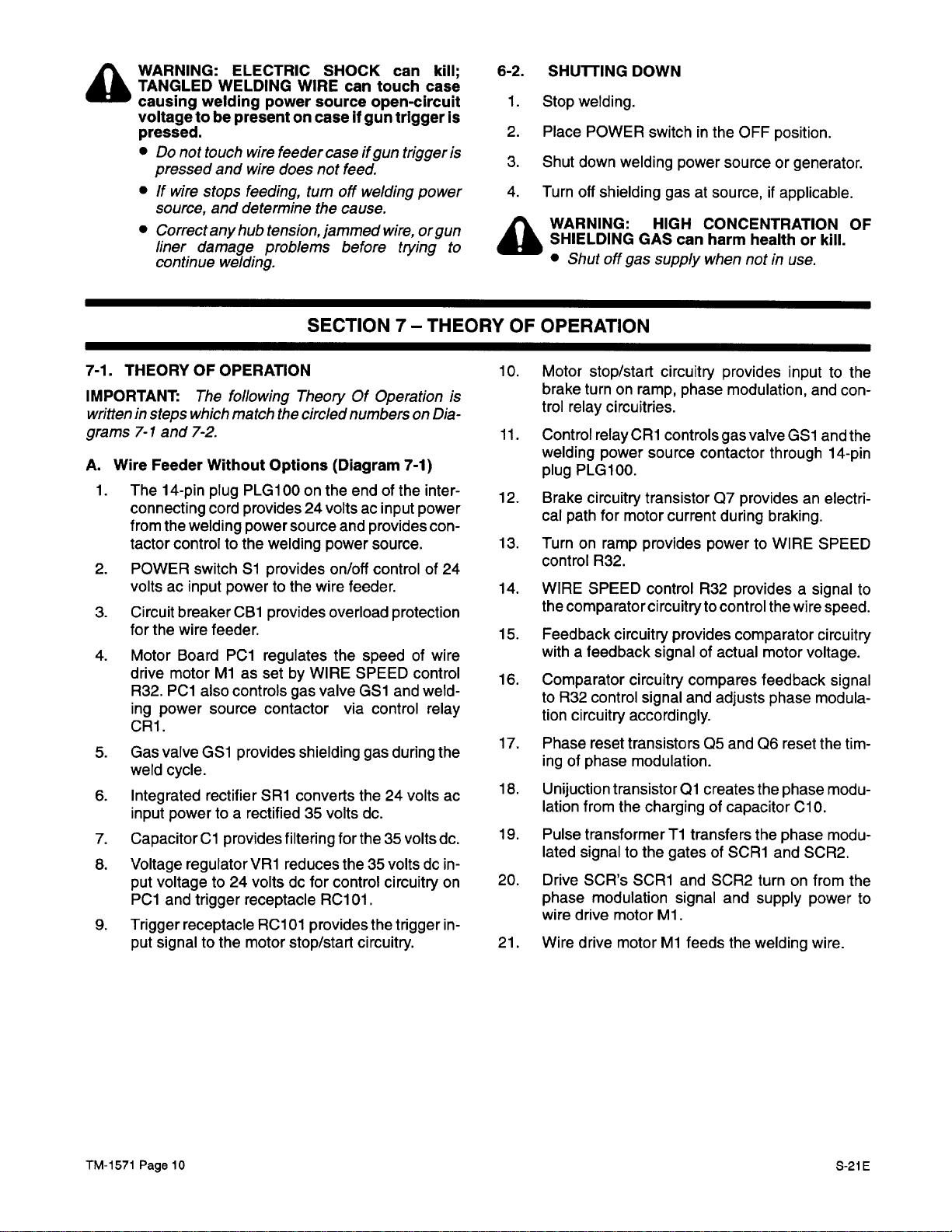
6-2.
A
-
SHUTTING
1.
Stop
welding.
2.
Place
3.
Shut
down
4.
Turn
off
WARNING: HIGH
SHIELDING
•
Shut
10.
Motor
brake turnonramp,
trol relay circuitries.
11.
Control
welding
plug
PLG100.
12.
Brake
cal
path
13.
Turnonramp
control
14.
WIRE
the
comparator circuitrytocontrol the
15.
Feedback circuitry
with
a feedback
16.
Comparator circuitry compares feedback
to
R32
tion
circuitry
17.
Phase
ingofphase modulation.
18.
Unijuction
lation
19.
Pulse
lated
signaltothe
20.
Drive
phase
wire
drive
21.
Wire
drive
DOWN
POWER switchinthe
welding
shielding
off
gas
stop/start
relay
power
circuitry
for
motor
R32.
SPEED
control signal
reset
transistorsQ5and
transistorQicreates
from
the
transformerTitransfers
SCR’s
modulation
motor
motorMlfeeds
power
gasatsource,ifapplicable.
GAS
can
supply
circuitry
phase modulation,
CR1
controls
source
transistorQ7providesanelectri
current
provides
control
provides
signalofactual
and
accordingly.
charging of
gatesofSCRi
SCRi
and
signal
Mi.
OFF
sourceorgenerator.
CONCENTRATION
harm healthorkill.
when
provides
gas
contactor
during
powertoWIRE
R32
providesasignal
comparator circuitry
adjusts
capacitor ClO.
SCR2
and
the
position.
notinuse.
inputtothe
and
valve
051
through
braking.
wire
motor
voltage.
phase
Q6 reset the
the phase
the phase
and SCR2.
turnonfrom
supply
welding
power
wire.
OF
con-
and
the
14-pin
SPEED
to
speed.
signal
modula
tim
modu
modu
the
to
-
-
-
-
-
TM-1571
Page
10
S-21E
Page 15
0
4-
0.
0
•1~
0
4-
1~
4)
4)
LI
-
4)
I
-
0
U
-
E
(U
I
-
0)
(U
0
0
1~
E
(U
0)
(U
0
S-21E
-A
c~
.~
~(i)
.~Q)
tb~.
~3O
c~o
I—0
ZQ)
TM-1571
Page
11
Page 16

B.
SpotlBurnback
7-2)
1.
Optional
controlofspot
back
2.
Burnback
of
the
onds.
Time
Spot/Burnback
weld
time.
potentiometer
burnback
time between
Control
time
and
R26 allows
Option (Diagram
Board PC2
provides
adjustmentofburn-
adjustment
0.02
and
0.25
sec-
3.
Spot
time potentiometer R25 allows
of
spot time
seconds
DIP
Switch
4.
Spot/Continuous
mal
untimed
cycle.
5.
Spot
time
short
range
(0.25to5
from
0.12to2.5
dependingonthe
secondsor0.25to5
settingofSpot
Sl.
switch
weld
DIP
switch51provides
S51
allows
cycleora timed
(0.12to2.5 seconds)orlong
seconds)
spot
time.
adjustment
Time
either a
spot
nor
weld
a selection
range
-
of
Diagram 7-2.
Block
Diagram
For
Spot/Burnback
Time
Control
Option
TM-1571
Page
12
S-21E
Page 17

Notes
S-21E
TM-1571 Page 13
Page 18

SECTION
8—
TROUBLESHOOTING
8-1.
The
testing
ohmmeter
greater
for
fied,
pedanceorgreater.
TESTING
TION
INSTRUMENTS
service proceduresinthis
instruments.
(DVM)
and
variable
useagood
diode
resistor
Useagood quality
with
one
megohm
check capability
testing). Ifanoscilloscopeisspeci
quality
If a
unit
circuit
with
coating,itwillbenecessary
needle probesinthe
Recoat
Digital
areasifnecessary
volt-ohmmeters
larity attention
meter
may
indicate
procedure specified
rect
polarity
appearsonthe
connectionstotest
8-2.
A
CIRCUIT
WARNING:
•
Do
not
•
Shut
source,
ing
inspecting,
test
areatoobtain
to retain
(DVM’s)donot
when making connections.
a—(negative)
a+(positive) voltage.Ifthe
display, reverse
points.
BOARD
touch live
down
and
HANDLING
ELECTRIC
electrical
wire
feeder
disconnect
lockout/tagging
maintaining,orservicing.
Lockout/tagging procedures
sistofdisconnecting
for
welding
line
disconnect switchinopen
ing
fuses
tagging
device.
(—)
battery
power
source
from
fuse box,orshutting
circuit
Stop
cable
breakerorother
engine,
from
erators.
A
MOVING
•
Keep
HOT
•
Allow
CAUTION:
(ESD)
•
Put
BEFORE
•
Transport
shielding
•
Perform
INCORRECT
plugs
•
Be
PARTS
away
from
SURFACES
cooling
can
on
period
ELECTROSTATIC
damage
properly
handling
circuit
carriersorpackages.
work
onlyata static-safe
INSTALLATIONormisaligned
can
damage
sure
that
plugs
can
moving
can
aligned.
EXCESSIVE
board.
•
Use
ment
board
TM-1571 Page
14
PRESSURE
only
minimal pressure and
when
plugs
disconnectingorconnecting
and
removingorinstalling
AND
INFORMA
manual
require
digital
input
impedance
(useananalog VOM
one
megohm
board
has
a protective
to remove
coatingoruse
proper
corrosion
protection.
require
However,
voltage
when
meter
PRECAUTIONS
SHOCK
can
parts.
and
welding
input
power
procedures
forwirefeedercon
interconnecting
cord,
consistofpadlocking
position,
off
disconnecting
and
disconnect
batteryonwelding
cause serious
parts.
cause
severe burns.
before servicing.
circuit
grounded
circuit
DISCHARGE
boards.
wrist
boards.
boardsinproper
work
circuit board.
are
properly
can
installed
break
gentle
-
proper
volt-
or
-
inputim-
contact.
leadpo-
the
the
test
incor
-
lead
kill.
power
employ
-
before
-
and
remov
and
-
red-
negative
gen
-
injury.
strap
static-
area.
and
circuit
move
-
board.
8-3.
A
TROUBLESHOOTING
gram
8-1)
WARNING:
•
Do
not
touch
•
Shut
down
source,
ing
and
lockout/tagging
inspecting,
Lockout/tagging procedures
sistofdisconnecting
for
welding
line
disconnect
ing
fuses
from
tagging
device.
(—)
circuit
Stop
battery
erators.
MOVING
•
Keep away
HOT
•
Allow
PARTS
SURFACES
cooling
Troubleshootingtobe
qualified
The
troubleshooting
of
the
troubles
circuit
normally
persons.
that
tiedtoground mustbeat
tial.
Use
the tableinconjunction
manual
in
ubleshooting
When replacing
replacement
ranty
Resistance
made
fore
IMPORTANT:
dures,
overheating
winding(s) failure
smoke,
are
ers,
rosion,
saves
IMPORTANT: Be
and
and
with
and
the exploded
the
Service
Parts Manual
procedures.
components,
parts.
repair by
with the
making
authorized
and
continuity
unit
resistance
Before beginning troubleshooting
visually
examine
and
failure.
are
and
smell.
relatively
incorrect
simple:
switch positions, loose
and
the
like.Acomplete,
considerable
secure according
switches
areinproper
troubleshooting.
ELECTRIC
live
electrical
wire
feeder
disconnect
(Table
SHOCK
8-1
And
can
parts.
and
welding
input
power
procedures
Dia
kill.
power
employ
before
maintaining,orservicing.
forwire
interconnecting
feeder
cord,
con-
and
power source consistofpadlocking
switchinopen
fuse box,orshutting
breakerorother
engine,
cable
from
from
can
moving
can
period
and
batteryonwelding
cause
cause
before servicing.
position,
off
remov
and
red-
disconnecting
disconnect negative
gen
serious
injury.
parts.
severe
performed
burns.
only
by
tableisdesignedtodiagnose some
can
developinthis
with the
views
use
MILLER parts
warranty
measurements
shut
down.
Isolate
and
continuity
wire
feeder.
ground
poten
diagramsinthis
and
component
values
while performing
only
genuine
are
required
service
MILLER
for
agency.
must
components
measurements.
Any
tro
war-
be
be-
proce
internalcomponents
Many
major problems,
usually
Fortunately
blown
apparentbydiscoloration,
most
fuses,
tripped
careful
time,
sure
money
that
and
all connections
to Section4and
positions
elect
before
for
signs
such
rical
pro
blems
circuit
break
connections,
inspection
cor
often
frustration.
are
correct
that
all
controls
proceeding
S-21E
of
as
-
-
-
-
-
-
-
-
-
Page 19

Table 8-1.
Troubleshooting
TROUBLE
Wire
does not feed.
Wire feeds
Wire feeds
erratically. Pressureondrive
but thereisno
flow.
Wire
does not
is
pulled
but
continuestofeed
after
triggerisreleased.
Gun nozzle
The
gas
rattling
ble
erraticorslow
opening
valveinthe
loudly
speed.
Motor
runs
but
gized
with
Spot/Burnback
tion
installed.
feed
until
restricted. Weld
feeder
along
with possi-
wire
wireisnot
gas
trigger
feed
ener-
Op-
CAUSE REMEDY
Circuit
breaker
CB1.
Looseorimproperly
trigger
Welding
connection.
Gun
trigger. See
gun
shorted.
Motor
Ml.
Motor
Control
Board
poor connectionstoPCl.
ficient.
Drive
roll
wrong size
size
used.
Drive rolls
Dirt in
Motor
poor
Gas valve
Motor
poor
Welding
tween
and
worn.
drive
rolls.
Control
Board
connectionstoPCi.
GSl.
Control
Board
connectionstoPCl.
gunisshorted
one of
the
weld
cable.
spatterorforeign
accumulation.
is
Welding
tween
and
gunisshorted
one of
the
weld
cable.
Spot/Burnback
poor connectionstoPC2.
made gun
PCi
or
rollisinsuf-
for wire
PCl
or
PCl
or
be-
trigger leads
matter
be-
trigger leads
Board PC2
Check
pressure
tion
Check
gun
(see
10-5).
gun
4-3).
gun
Owner’s
Repairorreplace
Check
connections
motor brushes
if
necessary.
Check
Check
tion
Rotate
connections
PCi
8-4.
Replace
pressure adjustment
clockwisein1/4
stops
slipping
Changetocorrect
4-2).
Replace
drive rolls
Clean drive rolls
Check
Check
tion
Check
tions
Replace
tion
8-4.
(see
Check
Check
8-4.
connections
PCi
Replace
GS1
GSlifnecessary.
connections
PCl
Replace
Repairorreplace
Carefully
matter
nozzle
metal
remove
which
opening.
tool.
Repairorreplace
or
Check
connections
PC2
according
Replace
PC2ifnecessary.
liner,
hub
Section
trigger
tension,
4).
connection
and
Reset
(see
CBl
Manual.
welding
(see
gun.
for
continuitytoMl.
Section
for
10-4).
continuitytoPCl.
accordingtoDiagram
PClifnecessary.
knob
turn
increments
(see
Section
size drive
(see
(see
for
4-2).
roll
(see
Section
Section
4-2).
l0-lC).
continuitytoPCi.
accordingtoDiagram 8-2
PCiifnecessary.
for
proper
Diagram
coil
voltage
8-1).
Check
continuityofcoil.
for
continuitytoPCl.
accordingtoDiagram
PClifnecessary.
welding
any
may accumulate
Use
welding
to Diagram
gun.
weld spatterorforeign
around the
a hardwood
gun.
for
continuitytoPC2.
8-3
and Section 8-5.
drive
(see
Section
Replace
8-2
and
counter
until
the
Section
and
and
8-2
and
stick,
roll
Sec
Check
Ml
Sec
wire
Sec
connec
Sec
never
a
Check
5-21E
TM-i
571
Page
15
Page 20

~
~
~U)
~Z
~
&E
~
a~
~
~e
!FI
—
—
~
C’J CO
O
O
O
O~,
~
..~
— —
ow
~
~
+oO
o1t~0
~
—
U)
L
O~
~
N
(oIr-~0)
a
c
~ ~
ca
a~
0
zz:~~
O~
~ ~
— — —
0
CO
; ;
s.a
~
~
—
~
21
—
—
in
0,
=
Ci)
—
in
0)
LI
-
4)
I
-
I-
0
IL
E
(U
I-
0)
0
4-
0
I
-
(n
I—
0.
C,
z
0
U
o
o
0
1110 ~-0)0)
UJ:
0~
•c~~—-a-
Q~0~n~
~
• ~
~
0
—
S
0..o
~ ~
Oc~
=0
q~00
~-n’
0
0)
4-
0
L
0
.~
.-
Ci)
0)
.~
~Q)
0.
~0
~
•~
S
0
~
Ci)~
a
0.
-.
0
a
a
S
-
~
0
~
-~
0
S
0
(0
4
.0
0
I
-
E
(U
I..
0)
(U
OJ
I
TM-1571
)
Page 16
> >
CO
S-21E
Page 21

8-4.
A
MOTOR BOARD
TION
(Figure
W
ARNING:
Do
not
•
Shut
ELECTRIC
touch
down
8-1
wire
sourceorstop
changing
meter
disconnectingorconnecting
A
MOVING
•
Keep
HOT
•
Allow
This
~
ized.
ollowing
form this
CAUTION:
(ESD)
•
Putonproperly
FORE
•
shielding
•
Perform
INCORRECT
plugs
•
Be
PARTS
away
from
SURFACES
cooling
procedure requires the
Only
qualified
standard
testing
ELECTROSTATIC
can
damage
handling
Transport
circuit
carriersorpackages.
work
INSTALLATIONormisaligned
can
damage
sure
that
aligned.
EXCESSIVE
board.
•
Use
ment
board
IMPORTANT:
the
continuityofleads between
where
checkisperformed.
the
connections
so
that
bad
connectionsorleads
the
problem.
PRESSURE
only
minimal pressure and
when
plugs
and
For all checks,besuretotest
and be
PCi
TESTING
And
Diagram 8-2)
SHOCK
live
electrical
feeder and
engine
before
leadconnections
can
cause
moving
can
period
parts.
cause
before servicing.
persons
safety practices
INFORMA
can
kill.
parts.
welding
power
making
and
before
any
leads.
serious
severe burns.
unittobe
familiar
injury.
ener
with
aretoper-
or
and
procedure.
DISCHARGE
circuit
grounded
circuit
boardsinproper
onlyata static-safe
circuit board.
plugs
boards.
are
properly
boards.
wrist
installed
can
break
gentle
strap
static-
work
area.
circuit
move
BE-
and
disconnectingorconnecting
removing
All
actual
checks
orin
the
stalling
board
and
and
the
board.
verify
area
shouldgothrough
terminal-to-terminal
and
corrosion
are
tests
not
-
A.
Preliminary
1.
Check
tacle
2.
Check
Checks
that
RC1onMotor
that
RC2onMotor
3.
Check
that
RC3onMotor
4.
Check
that
RC3onMotor
B.
Power
Supply
Input powerof24
pinsAandBof
present,
-
CBl
An
output
pin A
If
+24
Control
An
output voltageof+6.5 volts dc
check
for
proper operation
of receptacle
volts dc
Board
receptacle
POWER
voltage
are
PCl.
pin Cofreceptacle
with
gun
trigger
pressed.
at
pin C,
C.
Trigger
When
replace
the
gun
Motor
Circuit
triggerispressed, +19
presentatpin Bofreceptacle
common
dc
is
start/stop
ceptacle
control relay
-
D.
The0to
signal
wire
current
providing the
to
otherwise
when
the
gun
triggerisnot
then
suppliedtopin Aofreceptacle
control signal
RCltocontrol
CR1onPCi.
Wire
Feed Speed
+6.5 volts dc
shouldbepresentatpin Dofreceptacle
feed
speed
and
voltage
proper
wire
drive
motorMlthrough
(negative)ofreceptacle
present
Control
between pinsCandDof
Board
PCi.
jumper
volts ac
plug
PLGlissecureinrecep
Control
plug
PLG2issecureinreceptacle
Control
plug
PLG3issecureinreceptacle
Control
plug
PLG4issecureinreceptacle
Control
Circuit
Board
Board
Board
Board
PCl.
PCl.
PCl.
PCi.
shouldbepresent
RC4.If24
switch51and
volts ac
circuit
withanohmmeter.
of +24
volts dc
RC2
with
not
presentatpinA,replace
shouldbepresent at
respecttocircuit
shouldbepresent
RC2
with
respecttocircuit
If +6.5 volts dc
Control
Board
are
PCi.
volts dc
RC2
with
respecttocircuit
the
voltageatpinBshouldbe0 volts
pressed.
The
trigger
RCl
and
also suppliedtopinBofre-
gas
valve
GS1
and
Circuit
wire
feed
speed
command
command
feedback
voltage
signaliscomparedtothe
from
MotorMlthereby
outputof0
to +24
pinsD(positive)
RC4.If0
to +24
RC4,
volts dcisnot
replace
between
are
not
breaker
common.
Motor
at
common
not
present
should
be
signal
as a motor
contactor
input
RC2.
The
volts dc
and C
Motor
-
5-2iE TM-i57i
Page
17
Page 22

A
WARNING:
can
•Donot
•
Shut
engine
tions
•
Have
standardsafetypractices
dures.
•
Follow
static-sensitive
ELECTRIC
cause serious
touch
down
before
and
only
standard ESD precautionstoprevent damaging
injury.
live
electrical
wire
feeder
makingorchanging
before
disconnectingorconnecting
qualified
parts
SHOCK
parts.
and
welding
persons
perform
during
can
kill;
power
meter
familiar
with
troubleshooting
testing.
MOVING
sourceorstop
lead
any
and
following
PARTS
connec
leads.
proce-
-
o
to
6.5
mm.tomax.ofWIRE
control
voltsdcinput
with
6.5
voltsdcoutput
~un
from
SPEED
trigger
Not used
+24
volts
dc
output
/
+19
volts
gun
option,
with
with
after spot timeortrigger
dc Input
triggerpreseed
+24
gun
trigger
option,0voltsdcinput
released
volts
with
without
dc input
pressed
.29.1
RI&M
mwus
~e~n
+24
voltsdcinput
with
gun
pressed
trigger
TM-i
571
Page
18
Diagram 8-2.
Troubleshooting Circuit
Diagram
For
Motor
Control
Board
PCi
S-2iE
Page 23

IMPORTANT:
volt-ohmmeter
values.
For
are
AC,
with
shown
PLO4) unless
otherwise
specified.
For
DC,
the
(DVM)orequivalent
the
respecttocircuit
values are
values are
reading
RMS
readings.
common lead24(pinCof
otherwise indicated. The
based
on a
average
tolerances
.241.1
good
quality
(not
TheDCvoltages
RMS)
plug
are
±10%
unless
digital
24
voltsacinput
with
POWER
51
ON
24
switch
voltsacoutput
contactor
with
g
control
24
voltsacoutput
toasvalve
wit
gun
tr~ger
GSi
AC
circuit
common
S-2iE
+2W
DC
cirucit
common
TM-i57i
5D-124
Page
896
i9
Page 24

Figure
8-1.
Motor Control Board
PCi
Component Locations
And
Information
Receptacle
RC3
Receptacle
RC4
SA-123
147-E
8-5.
A
A
TM-i57i
OPTIONAL SPOTIBURNBACK
TESTING
Figure
WARNING: ELECTRIC
•
Do
•
Shut
sourceorstop
changing
disconnectingorconnecting
MOVING
•
Keep
HOT
•
Allow
This
ized.
p
ollowing
form
CAUTION:
(ESD)
•
Putonproperly
FORE
•
Transport
shielding
•
Perform
INCORRECT
plugs
•
Be
INFORMATION
8-2)
not
touch
live
down wire
electrical
feeder
(Diagram
SHOCK
and
engine
meter
lead
connections
PARTS
away
SURFACES
cooling
can
from
period
cause
moving
can
parts.
cause
before servicing.
procedure requires the
Only
qualified
standard
this testing
ELECTROSTATIC DISCHARGE
can
damage
persons
safety practices
procedure.
circuit
grounded
handling circuit
circuit
boards.
boardsinproper
carriersorpackages.
work
onlyata static-safe
can
sure
INSTALLATION
damage
that
circuit board.
plugs
are
properly
parts.
welding
before
any
serious
severe
unittobe
familiar
boards.
wrist
or misaligned
aligned.
Page
20
BOARD
8-3
can
kill.
making
and
before
leads.
Injury.
burns.
with
aretoper-
strap
work
installed
PC2
And
power
or
ener
and
BE-
static-
area.
and
EXCESSIVE
board.
•
IMPORTANT:
the
continuityofleads between
where
checkisperformed.
the
connections
so
that
bad
the
problem.
A.
Power
Input
power
pinsAandB(DC
+35
-
volts dc
secureinreceptacle
plug
PLG1is
Board
PCl.If+35
Motor
Control
B.
Trigger
A
trigger
at
mon
input
pin Dofreceptacle
when
shouldbepresent
+19
volts dc
pressed,
check
8-4.
C.
Motor
When
the
voltage
of +24
PRESSURE
Use
only
ment
board
minimal
when disconnectingorconnecting
plugs
pressure and
and
removingorinstalling
For all checks,besuretotest
the
All
checks
andbeactual
connectionsorleads
Supply
of +35
Circuit
volts dc shouldbepresent between
circuit
are
not
present,
terminal-to-terminal
and
common)ofreceptacle
check
RClonBurnback
secureinreceptacle
volts dc
Board
PCl
Circuit
voltage
of +19
RCl
the
gun
triggerispressed, and
when
the
are
not
present
Motor
Board
StartlStop
gun
triggerispressed,
volts dc
Circuit
shouldbepresentatpin Aofre
RClonMotor
are still
according
volts dc shouldbepresent
with
respecttocircuit
gun
when
PCi
a motor
can
break
gentle
circuit
move
board.
and
verify
board
and
the
area
shouldgothrough
tests
corrosion
are
not
RCl.
that
plug
PLG51
Board PC2
and
Control
not present,
check
to Section 8-4.
com
0 volts dc
triggerisreleased.
the
gun
trigger
according
to Section
control
output
S-2iE
-
If
is
-
If
is
-
Page 25

ceptacle
motor
RC2
with
respecttocircuit
and
0 volts dc shouldbepresent
triggerisreleased to
not
presentatpin A
place
Spot/Burnback
D.
Contactor
When the
present at
Control
gun
triggerispressed
pin Dofreceptacle
stop
when
Board
Circuit
the
motor.If+24
the
gun
PC2.
RCl
common to
when
volts dc
start
the
the
gun
are
triggerispressed,re-
and +19
Spot
DIP
volts dc
with
respecttoDC
Time
Switch
Si
are
circuit
common,acontactor
+24
volts dc
RC2
with
gerisreleased,
shouldbepresentatpin Bofreceptacle
respecttocircuit
0 volts dc shouldbepresent at
teradelayof0to0.25
setonBurnback Potentiometer
not
presentatpin B
volts dc
replace
are
Spot/Burnback
not
when
present
control
common.
seconds dependingonthe
R26.If+24
the
gun
when
the
Board
P02.
output voltage
When the
gun
trig
pinBaf
time
voltsdcare
triggerispressedor0
gun
triggerisreleased,
of
-
-
Figure
8-2.
Optional SpotlBurnback
Board
PC2
Component Locations
And
Information
SA-125
969-C
S-2iE
TM-1571
Page
21
Page 26

A
WARNING:
can
•Donot
•
Shutdown
engine
tions
•
Have
standardsafetypractices
dures.
•
Follow
static-sensitive
ELECTRIC
cause serious
touch
live
wire
before
and
only
makingorchanging
before
qualified
standard
Inlury.
electrical
feeder
disconnectingorconnecting
ESD
parts
SHOCK
persons
during
can kill;
MOVING
parts.
and
welding
power
meter
familiar
perform
precautionstoprevent damaging
testing.
with
troubleshooting
source
lead
any
and
following
PARTS
or stop
connec
leads.
proce
-
-
Spot time
potentiometer
R25
+35
TM-1571
volts
input
Page
UIN GND
dc
Circuit
common
Diagram 8-3.
22
TRIGGER
+19
voltsdcInput
gun
trIgger
with
pressed
Troubleshooting Circuit
Diagram
For
Optional
SpotlBurnback
Board
PC2
Not
used
S-21
/
E
Page 27

IMPORTANT:
volt-ohmmeter
values.
shown are
PLG5I)unless
otherwise specified.
For
(DVM) or equivalent
For
AC,
the
with
respecttoDC
otherwise
Burnback
potentiometer
DC,
values
R26
the
values
are
based
are
indicated. The
reading
RMS
readings.
circuit
common lead71(pinBof
on a
good
average
TheDCvoltages
tolerances
quality
(not
RM5)
are±10%
digital
plug
unless
common
S-21E
I,
O
voltsdcduring spot
time,
0.7
spot time
Spot position,0volts
contInuous
voltsdca~er
do
with
with
S51 in
position
S51
in
Not used
‘4
+24
voltsdcoutput
for
motor
circuitry with
trigger
voltsdcafter spot
stop/stan
gun
pressed,
time
Not
used
0
+24
for
with
gun
0
burnback
TM-1571
contactor
voltsdcoutput
voltsdoafter
trigger
Page
output
pressed,
time
80-125
23
971
Page 28

SECTION
0
0.
a.
(U
9—
COMPONENT
IDENTIFICATION
6)
6)
‘U
AND
LOCATION
6)
‘S.—
0~-
•
.~
Ci)
0
4-
(U
0
0
-J
0
—
0
(U
0
4-
‘4-
4-
4)
4-
4)
0
0.
E
0
C.)
TM-1571
Page24
0’
4)
I
-
0)
6)—,
&2
E~.,
1
~ .2
CO
•
6)
0.
6)
E
0
z
0.
S-21E
Page 29

SECTION
10—
MAINTENANCE
10-1.
IMPORTANT:
this
maintainedina
when
numberofprecautionary
A
*Frequencyofserviceisbasedonunits
hours
usage
A.
A
Every
insideofthe
and
cleaning
sent,
A
S-21E
ROUTINE MAINTENANCE
unit
for
legibility
necessary.
WARNING:
•
Do
not
•
Shut
source,
ing
spectIng,
Lockout/tag9ing procedures
consistofdisconnecting
and
for
locking
removing fuses
and
red-tagging
necting device.
negative
ing
generators.
•
Allow
•
Do
not
maintenanceongun.
Troubleshootingtobe
fied
persons.
Table
Frequency*
Every
Month
Every6Months
per
week.
exceeds40hours
Internal
useaclean, dry
clean
B.
Inspection
Cleaning
ARNING:
tionatbeginning of
fore
proceeding.
month,
blow
wire
operation.Ifdustyordirty
the
ARNING:
tionatbeginning
fore
proceeding.
Every
six
months inspect
All
precautionary
clearly
touch
down
and
lockout/ta
welding
line
(—)
gun
depress
10-1.
Increase
feeder.
unit
and
readable
See
Service
labels.
ELECTRIC
live
electrical
wire
feeder and
disconnect
ggin9 procedures
maintaining,orservicing.
power
disconnect switchinopen
from
circuit
Stop
battery
and
Units in
ments:
clean internal
Check
block,
and
drive rolls
Read
ourorvacuum
airstreamorvacuum
monthly.
cable
unittocool before
gun
Maintenance
heavy
Check labels,
all
Section
cables
frequencyofmaintenance
per
and
Remove
Upkeep
Read
and
of entire
state
Parts
SHOCK
input
interconnecting
source
fuse box,orshutting
breakerorother
engine,
from batteryonweld-
trigger
performed
Maintenance
service
parts
labels
10-1).
(Section
(Section
week.
follow
entire
dust
the
follow
(Table
labels
Manual
parts.
power
for wire
consistofpad
and
while
Schedule
and
(see
10-1
l0-lC).
safety
Section
and
outer
conditions
safety
Section
10-1)
the labels
and replaced
can
welding
beforein-
disconnect
touching.
performing
onlybyquali
environ
weld
drive
IMPORTANT
Inspectqun
B).
operated
dirt
enclosure,
suction
on
must
be
for
part
kill.
power
employ
feeder
cord,
position,
off
discon
cables,
rolls.
Clean
40
if
informa
10-1be-
from
the
for
the
are
pre-
Informa
10-1be-
Every
dustyordirty
monthly.
1.
2.
3.
-
4.
-
A
-
5.
-
6.
C.
A
Itisnecessary
ingofthe
installation
-
IMPORTANT:
can
the
1.
2.
-
3.
4.
six
months,
Inspection
Unlatch and
Inspect
parts;
Repairorreplace,asrequired,
ble;
cracked
bles
Remove
moisture
CAUTION:
CLES
equipment.
•
Point
from
ing
Blow out the
pressed
any metal
lated.
Close
CleaningOfDrive
WARNING:
tionatbeginning of
fore
MOVING
•
Keep
HIGH
damage to
•
Do
if
drive
wire
resultina
efficiencyofthe wire
Remove
each
Using
particlesinthe
Reinstall
Resume
inspect
conditions
gun
tighten,
give
particular
insulation
enter equipment.
grease
from
can
gun
personnel and
with
air
when
chips
and
secure
proceeding.
PARTS
away
ROTATIONAL
not
allow
compressed
roll
to remove
grooves
instructions).
Failuretoproperly
buildupofwire
the
drive
roll,
wire
drive rolls according
operation.
the
are
should
open
for
FLYING
compressed
Read
drive
assembly
three drive
brush,
consistofthe
left
case
broken
repair,
and
attentiontofrayed
and areas
and grime
electrical
DIRT
injure personnel
liner
onlyina
gun
wire
changing
and
dirt
left
case
Rolls
and
can
from
moving
rolls
drive
rollstorotateathigh
airisused
the
drive rolls
(see
Section
Useawire
feeding
and remove
remove
wire
grooves.
gun,
present,
areas,
parts
equipment
air.
guide
that
follow safety
entire
cause
SPEED
and
particles
roll
hoses, and
access
cracks,
replaceasrequired.
all
where
from
and
AND
safe direction away
wire.
may
access
Section
serious
parts.
injure
4-2
brush to
maintain
which
operation.
securing
drive
the
to Section 4-2.
cables.
inspect
METAL
liner
This
for
for
for
buildupofwire
the
unit
following:
door.
and
loose
hose
andca-
and
hose
andca-
components,
cable.
PARTI
and
damage
when
clean
with
com
will
remove
have
accumu
door.
informa
10-1be-
injury.
may
cause
personnel.
speed
cleaning
properclean
removal
clean
the drive
decreases
screws
rolls.
TM-1571
the
and
rolls.
rolls
from
Page
If
-
-
-
-
-
-
25
Page 30

10-2.
A
The
feed
quire
roll and
mentisnecessary,
Behind
obtain
guide,
move
with
ALIGNING
(Figure
W
•
Lockout/tag
consistofdisconnecting
and
lockin9
removing
and
necting device.
negative
ing
MOVING
•
HOT
•
Maintenancetobe
persons.
drive
properly.
readjustment.Tocheck
wire
the drive
proper
rotate
drive
wire
Wire
10-1)
ARNING:
Do
not
touch
Shut
down wire
source,
employing
be
ore
workingonfeeder.
for
welding
line
fuses
red-tag9ing
(—)
generators.
PARTS
Keep
away
SURFACES
Allow
cooling
roll and
guide
Guide_-
wire
Alignmentisfactory set
guide positions
roll
alignmentofthe drive
drive
rollinor
(see
DRIVE
and
9ing procedures
disconnect switchinopen
battery
proceed
mounting
roll
out
ROLL
ELECTRIC
live
lockout/tagging
power
from
circuit
Stop
from
period
guide
mounting
until
Figure
SHOCK
electrical
feeder and
disconnect
interconnecting
source consistofpad
fuse
breakerorother
engine,
cable
from batteryonweld-
can
cause
moving
can
cause
before servicing.
performed
mustbealigned
alignment,
with
as follows:
hubisa
hub
grooveindrive
10-1).
AND
WIRE
can
parts.
welding
input
procedures
for wire
box,orshutting
and
serious
parts.
severe
onlybyqualified
and
should
compare
Figure
10-1.Ifalign
spring washer.
roll
with
securing bolt,
Welding Wire
GUIDE
kill.
power
power
feeder
cord,
-
position,
off
discon
disconnect
injury.
burns.
for wire
the
roll
lines
-
to
notre-
drive
-
To
wire
and
up
10-3.
A
Ifitshould
assembly,
the
REINSTALLATION
ure
WARNING: ELECTRIC
•
Do
•
Shut
source,
ing
ingonfeeder.
Lockout/tagging procedures
sistofdisconnecting
for
line
ing
tagging
device.
(—)
erators.
obtain
assembly.
1.
Slide the
shaftinorder
a.
Fiber
b.
Brake
c.
Hub
d.
Brake
e.
Fiber
f.
Keyed
g.
Spring
h.
Wire
i.
Wire
j.
Spanner
k.
Retaining
2.
Rotate
tated
hub.
3.
Install
OF HUB
10-2)
not
touch
live
electrical
down
wire
feeder and
and
disconnect
lockout/tagging
welding
disconnect
fuses
battery
become necessarytoreplace
power
from
circuit
Stop
cable
part and
following
Washer
Washer
Washer
Washer
Washer
Reel
Retainer
Nut
Ring
bolt into
only
untilaslight
retaining
engine,
given:
interconnecting
source consistofpadlocking
switchinopen
fuse box,orshutting
breakerorother
from
proceed
items
support
ringonhub.
ASSEMBLY
SHOCK
parts.
input
power
procedures
for wire
position,
and
disconnect negative
batteryonwelding
as follows
onto
the
shaft.
Bolt shouldbero
dragisfelt while
(Fig
can
kill.
welding
disconnecting
any
spool
power
employ
before
work
feeder
cord,
remov
off
and
partofthe
to reinstall
support
turning
con-
and
red
gen
-
-
-
-
-
-
-
CORRECT
ALIGNMENT
Drive
Roll
Washer
INCORRECT
ALIGNMENT
Secrurlng
Bolt
Figure
TM-1571 Page
A
10-1.
ReinstallationOfHub
26
Drive
Mounting
V
ViewIsfrom
of
feeder
down
with
roll
assembly
I
Assembly
Roll
Hub
top
looking
pressure
open
SA
145763
10-4.
A
1.
BRUSH
WARNING: ELECTRIC
•
•
Lockout/tagging procedures
sistofdisconnecting
for
line
ing
tagging
device.
(—)
erators.
Remove
drive
INSPECTION
Do
not
touch
live
Shut
down wire
source,
ing
ingonfeeder.
welding
fuses
battery
and
power
from
circuit
Stop
engine,
cable
two
brush caps
disconnect
switchinopen
fuse
breakerorother
lockout/tagging
disconnect
motor.
AND
SHOCK
electrical
feeder
procedures
interconnecting
source
from
consistofpadlocking
box,orshutting
and
batteryonwelding
locatedonend of
REPLACEMENT
can
kill.
parts.
and
welding
input
power
forwire
position,
disconnecting
disconnect negative
power
employ
before
work
feedercon
cord,
and
remov
off
and
red-
gen
S-21E
the
-
-
-
-
-
Page 31

2.
Remove
3.
Examine
chippedorbrokenorif
of brush
4.
Install
brushes, and
10-5.
Circuit
circuits.
OVERLOAD PROTECTION
breaker
CBlislocated
brushes.
brushes. Replace
less
material
remains.
secure with
CBl
provides
towards
protectiontothe
the
brushesifthey
than
1/4
in.
(6.4
caps.
frontofthe
unit,
are
mm)
feeder
be-
hind
the
left
case access
loadorthe circuit
down
the
wire
feeder.IfCB1
and
manually
To
reset
1.
2.
3.
Unlatch and
Locate
Close
CBl,
reset the
proceed
CBl,
and
fail,
the
breaker.
as follows:
open
and
secure
door.Ifthe
breaker
opens,
left
case
reset
(see
left
case
motor
would
correct
access
Figure
access
should
trip
and
over
shut
the problem
door.
4-1).
door.
-
S-21E
TM-1571
Page
27
Page 32

The
followingisa
1.
Know
2.
Use
3.
Call
listofall
unit
Model
Listtofind
the
Technical
Table
diagrams
and Serial or
diagram
number.
Publications
SECTION
11-1.
for
Style
11-ELECTRICAL DIAGRAMS
ListOfCircuit
models
covered by this
Diagrams
Number.
Departmentat414-735-4356.
And
Wiring Diagrams
manual.Toorder diagrams
needed, proceedasfollows:
Model
S-21E
Circuit
Circuit
Board
Board
•
Optional
PCl
PC2.
SerialOrStyle
JJ507797
JJ507797
JJ507797
JK742029
and
and
thru
and
Number
following
following
JK742028
following
Circuit
SB-124
SD-124
SC-122
SC-125
Diagram
895-B
896-A
194
971
Wiring
SB-l
24816-B
Diagram
SM-1571
Page
28
Page 33

PLGIOO
A
.(~a
0 ~
B
‘E-.-.<~~
—~
~<*z~O
o-’--cX2—~----’—«
4
N
2;
ACIOI
lUIGGER
R~TA~.E
£~G~Li<
—
mc4-A
~<Rc4-B
~<
A~-0
I
RC4-C
RC4-0
«mci-c
«mci-v
Pci
Ai~-o>
mci-a>
mci-A
mci-c
»—l
~WhED
.17
.M
r
I I
mcs-s»
I
mc3-A»
I
I
I
I
I
I
~AOC
I
L
mci-v»
mci-c»
mci-o>~
mci-c
mci-s
mci-A
RCO-A
Rca-s
___
K
31
~
>~ ~<
>~
SPOT/BURNBACK
OPTION
«mci-E
~ ~<
~
~<mci-O
mci-v
~<
mci-c
BOARD
mci-A
mci-s
I
I
I
I
I
I
I
Diagram
11-1.
Circuit
Diagram
For
S-21E
Effective
With
Serial
No.
JJ507797
Circuit
And
Diagram
Following
No.
SB-i24895-B
Diagram
11-2.
Wiring
Diagram
For
S-21E
Effective With
Serial
No.
JJ507’797 And
Wiring
Diagram
Following
No.
SB-i24816-B
SM-1571 Page
29
Page 34

0~
cr
0
I
-
0
I
-
z
0
Li
0.j
.5
E
Ii
U,’
-
S
S
I
(0
0)
(0
N
6
C’)
6
z
E
(U
I-
0)
~
~
~
~
U
I
0’
_
0
IL
~
-
0’
I.
-
0
It)
6
z
L.
4)
U)
4-
4)
4-
U
4)
w
C.)
a.
0
I...
(U
0
(0
.5
I..
4-
I
SM-1571
Page 30
I
-
0
0~
r
-,
L
.1
I
I
I
I-
ci.
0 0
CD
I-
C.)
0
0
4-
0L.0
IL
E
0
I-
0)
(U
4-
U
I
C”
E
(U
I..
0)
0
-
Page 35

0’
N
N
1~
(
Cl)
6
z
E
0
(U
I-
0)
(U
0
4-
0
I
G
N
0
N
I’
-
I
-
-
I
-
0’
0
LI)
Rca-A
mci-c
mci-c
mci-c
MCI
6
z
4-
4)
w
a.
I-
(U
0
-F
.0
U)
0
IL
0
4-
0
(U
C
I
0.
C
0
a.
I-
0
E
(U
0)
-
mci
-o
mci-n
MCI-A
SM-1571
Page
31
0
I
-
q~i
I
-
E
(U
L.
0)
0
Page 36

1~
0’
LI)
N
6
U)
z
0
6
E
(U
1~
0)
(U
o
I-
0)
C
0
IL
C
0’
N
0
N
I’
6
z
I-
4)
U)
4-
4)
0
4)
w
N
C.)
a.
0
I-
(U
0
-
0
(U
.0
C
I
0
a.
U)
C
0
4-
0.
0
I..
0
IL
E
(U
L.
0)
(U
0
4-
I
(3
I..
0
C.)
E
(U
0)
(U
-
-
SM-1571
Page 32
Page 37

MiIIeE
November1996
Effective With
Form: TM-1571
Serial
No.
JJ507797
SECTION
12-
PARTS
LIST
S-21E
S-21E
Wire
Feed Equipment
TM-1571
Page
33
Page 38

CO
0
N
C—
Ci)
.0
E
4)
U’
U,
N
in
C%J
1~
4)
I
-
0)
IL
N
C,J
Ci)
E
a)
Ci)
a)
V
=
TM-i
571
Page34 S-21E
Page 39

Item
No.
Dia.
Mkgs.
Part
No.
Description
Quantity
...
1
2
...
3
...
4
...
5
...
6
7
...
8
...
9
..10
11
12 124
13
..14
15
16
..17
127 232
151
828
112 031
111
523
114
415
092 237
089 477 SPRING,
085 244
089
562
010224 PIN,springcs.187x1.000
090416
817 HOUSING,
602 243
602213
601
966
604
538
124778
..18 124819...
18 130 365
..19
20
20
21
22 107
23
.24
25
..25
090440...
604
668
601
880
010
291
983
071
602
010494...
092
200
131
181
26
..27 134834...
..28....
GS1
109930...
010296...
010 869
112090...
..28....
29
- .
29 137
-
29
.30
-
.
30 152
31
-
32
33
34
35
36
-
.
37
37
38
.39
..40
41
..42
43
44 122
44 137
..45 122339...
S-21E
GS1
125785...
089
572
089 573
304
089 572
089573...
+122313...
725
134
464
090 439
126
873...
072 094
058 427
141
700
605
941
072 292
154 098
010 233 SPRING,
057
971
010191
058 628
058428
135
205
430...
461
Figure
...
12-1.
DRIVE
ASSEMBLY,
PIN,
cotter-hair
LEVER,
BEARING,
SCREW,
KNOB,
adjustment-tension
WASHER,
FASTENER,
PIN,
hinge
WASHER,
WASHER,
SCREW,
WASHER,
Main
Assembly
wire
(consisting
.042x.750
pressure-roll
ball
.315x.866
x
.275
phillips-flathd10-24x.625
cprsn
.770ODx
cupped
stl
1.000
.328IDx
wire
.812ODx
pinned
wire
drive
flat
stl std
.378
lockstlsplit.375
cap
stl
hexhd.375-16x1.250
flat
stl SAE
.312
of)
x
.715p1d
.125
KNOB
INSULATOR,
...
INSULATOR,
housing
housing-drive
drive
(PriortoKA759476)
(Eff
w/KA759476)
INSULATOR,coverhousing
...
NUT,
stl
slflkg
hex
med
fnsh
.500-20 (Prior
...
NUT,
stl
hex
jam
.500-13
...
WASHER,
...
BLANK,
...
LABEL,
BUSHING, snap-in
...
WIRE
...
WIREGUIDE&NUT,(Effw/JK702158)
PLATE,
flat-nylafil
snap-in
caution
GUIDE
identification
nyl
high frequency
&
NUT,
(Eff
w/JK7021
.625IDx
.SOOmtg
nyl
inlet
control panel
hole
1.375
IDx
(PriortoJK7021
1.250ODx
will
damage
l.7SOmtg
(orderbymodel
to JK7021
58)
.l2Sthk
etc
hole
58)
HOSE,SAE.l87lDx.4100D(orderbyft)
VALVE,24VAC2wayl/4lPSxl/8orf(PriortoJK6l7847)
FITTING,
...
FITTING,
FITTING,
hose
brselbml/4NPTx
pipe
brs bushing
pipe
brs
elb
1/8NPTx3/16
1/4
.625-l8RH
x
l/8NPT
(Prior
hose
(PriortoJK61
VALVE,24VAC2wayl/8orf(EffwIJK617847)
...
CATCH,
...
PLATE,
...
LATCH,
...
CATCH,
PLATE,
WRAPPER
...
WRAPPER
...
LABEL,
...
LABEL,
BUMPER,
...
HUB
link-lock
keeper
door
link-lock
keeper
(PriortoKA848999)
link-lock
(Eff
w/KA848999
(Eff
link-lock
(Priorto
(Eff
w/KC261
warning
warning
general
electric
polyurethane polymer
&
SPINDLE ASSEMBLY,
RING,
RING,
WASHER,
SHAFT,
SHAFT,
retaining-spool
retaining
spool
spool
flat
ext
stl
support
support
compression
WASHER,
flat
stl
(PriortoKA848999)
thru
w/KC261
810
(Effw/KC261810)
KC261810)
810)
precautionary
shock
can
.500
(consisting
.625
shaftx.OSOthk
.640IDx
1.000OD(Eff
(Prior
to KC237900)
(Eff
w/KC237900)
.970ODx
keyed
l.SOOdiax.l2Sthk
KC261
and
on)
kill
.120
809)
of)
(Eff
w/KC237900)
wire
WASHER,fbr.656lDx1.5000Dx.l2Sthk
WASHER,
brake
HUB,spool
NUT,
stl
...
BASE,
BASE,
FOOT,
slflkg hex
(Prior
to KA848999)
(Eff
w/KA848999)
rubber
reg
.625-11
1.2SOdiax1.125
high
(PriortoKA848999)
lip
58)
and
serial
number)
(PriortoJK617847)
to JK617847)
7847)
w/KC237900)
x 1.250
pld
TM-i
571
1
1
1
1
1
1
1
1
1
1
1
1
1
1
1
1
1
1
1
1
1
1
1
2
1
1
1
1
.
1
2ft
1
1
1
1
1
1
1
1
1
1
1
1
1
1
1
1
1
1
1
1
1
1
1
2
2
1
1
1
1
4
Page
35
Page 40

Item
No.
Dia.
Mkgs.
Part
No.
Description
Quantity
..45
..46..
PLG100....
134306.
144310.
134732.
..47
..46..
PLG100....141
079739.
134731.
..47
..48
..49
143922.
007826.
605227.
120304.
..50
..51....
..52....
CBl
PCl
PLG1
115104.
123745.
123148.
115093.
113746.
PLG2
PLG3
115092
113
131
113
PLG4
115
113
..53
..54
..55
..56
..57
Ml
110375...
123810...
092865...
605308...
122741...
~136745
..58
..59....
..60
..60
..60
R32
079625...
073562...
124720...
137814...
153612...
.61
..62
..63
..64...
51
RC1Ol
....
097922...
111997...
048282...
079534...
..65
..66
..67
..68
..69
..70
..71
..71
..71
..71
..71
..72
057084...
058549...
605758...
079626...
000418...
602241...
124818...
•087130...
•053695...
•079726...
•079728...
124820...
•108008...
+When
*Recommended
•
BE
orderingacomponent originally
Spare
Parts.
OPTIONAL
SURETOPROVIDE MODEL
162.
746
054
746
094
746
Figure
FOOT,
12-1.
Main
Assembly
rubber1.2SOdiax1.375
CONNECTOR&PINS,
....
CONNECTOR,
....
CONNECTOR,
circ
circ
CONNECTOR&PINS,
CONNECTOR,
....
CONNECTOR,
CABLE,
NUT,
BLANK,
No.
nyl
snap-in
hex jam
CONNECTOR,
CIRCUIT
CIRCUIT
BREAKER,
CARD,
circ
circ
18/3c
(orderbyft)
.750,
nyl
.2SOmtg
clamp-cable
motor
CONNECTOR&SOCKETS,
....
CONNECTOR,
rect
CONNECTOR&SOCKETS,
CONNECTOR,
...
CONNECTOR&SOCKETS,
CONNECTOR,
...
CONNECTOR&SOCKETS,
CONNECTOR,
STAND-OFF,
STAND-OFF,
KEY,
.122x.123x.750
RING,
MOTOR,
retaining
gear 24VDC
rect
rect
rect
support
support
BRUSH&SPRING
WASHER, spring
stl
POTENTIOMETER,Cl/T
CASE
ASSEMBLY,
CASE
ASSEMBLY,
CASE
ASSEMBLY,
NAMEPLATE,
KNOB,
SWITCH,
pointer
rocker
(Prior
(Eff
(Eff
(orderbymodel
SPST
CONNECTOR&SOCKETS,
CONNECTOR,
BUSHING,
GUIDE,
wire-Inlet
SCREW,
SCREW,
SCREW,
WASHER,
ROLL,
ROLL,
ROLL,
ROLL,
ROLL,
HUB,
REEL, wire
drive-combination
drive-V-grooved .023 wire
drive-V-grooved .030 wire
drive-V-knurled
drive-V-knurled
mtg-roll
displaying a
AND
SERIAL
mach
mach
cap
circ
snap-in
1/16
stI
rdh
stl
filh
stl
hexhdslf
flat
stl
SAE
drive
(Fig
12-2)
precautionary
NUMBER
nyl
(Continued)
high
(Prior
to KB041147)
pin
push-in
clamp
(Eff
pin
push-in
clamp
(Eff
20-24ga
str
rlf
17-20
w/KB041147)
14-l8ga
str
rlf size 17-20
w/JK617847)
.500
manual
reset1P4A25OVAC
control
(Fig
12-3)
(consisting
skt
24-lBga
Molex
(consisting
skt
24-l8ga
Molex
(consisting
skt
24-l8ga
Molex
(consisting
skt
24-lega
Molex
122RPM (consisting
ASSEMBLY
.500
2W
10K
ohm
to KA848999)
w/KA848999
w/KC261810
1OA
25OVAC
and
thru
and
serial
(consisting
skt
push-in
.250ODx
14-lBga
.375mtg hole
10-32x1.000
10-32x.875
1kg
.250-20x.500
.250
large
.035
wire
.045
wire
label,
the
WHEN
ORDERING
(consisting
Amp213605-1
Amp 206322-2
(consisting
Amp
of)
213603-1
Amp 206070-3
of)
39-00-0038
of)
39-00-0038
of)
39-00-0038
of)
39-00-0038
of)
KC261
809)
on)
number)
of)
Amp
66358-6
label
should
alsobeordered.
REPLACEMENT
of)
4
1
14
1
1
14
1
llft
1
3
1
1
1
1
6
1
8
1
2
1
4
2
2
1
1
1
2
2
1
1
1
1
1
1
1
1
4
1
1
3
3
1
1
1
1
1
2
2
1
1
PARTS.
TM-1571 Page
36
S-21E
Page 41

Item
No.
Part
No.
Description
Quantity
108 008
1
124904...NUT,spanner-spoolsupport
2 124
3
124 900..SUPPORT,
905..
1
Figure
RETAINER,
12-2.
spool
reel-spool
Reel,
-
Wire
(Optional)
support
1
1
1
2
3
BE
SURETOPROVIDE MODEL
AND
Figure
SERIAL
12-2.
NUMBER
Reel,
WHEN
Wire
ORDERING REPLACEMENT
Ref.
PARTS.
5C-127
305
S-21E
TM-1571
Page
37
Page 42

SA-123 147-F
TM-1571
Page
38
Figure
12-3.
Motor
Control
Circuit
Card
PCi
S-21E
Page 43

Dia.
Mkgs.
Part
No.
Description
Quantity
PCi
A1,2
Cl
C2
123
148
009159
039482
039481
C3,6,37,38,50
51,53-56,59
C4,5,8
C7,12
C9
....
ClO
Cli
C52
...
C60-62
CR1
D1,2,8,12
D3
D5
D6,7,9,10
Dli
....
122723
119198
000340
077206
031
693
035522
119197
053
991
099018
026202
087294
037250
028351
032210
092 648
Ji-lO
...
Q4,5,6
R3,5,7,8
...
R4,31
...
R6,22
R9,17,33
RiO
Ru
01
07
R2
092648
039355
037 200
121129
028284
093 037
044 789
072
559
000885
035829
035888
R12,14,24,26,40.072560
R13
Ri
5,35
....
R16
...
RiB
....
R19
R20
-
...
R21 039
-
...
R23
....
R25
....
R29
....
R30
-
...
R32
....
R34
R50,53,56
R51
,52,54,55
...
RC1
....
RC2
....
RC3
....
RC4
SCRi
,2
....
SRi
Ti
VR1
...
006424
035 828
052 143
093
041
093 030
052
139
106
108
437
030
105
084 205
030 098
072 677
108
436
605 919
605 918
114
654
113
749
117
038
113
748
080 508
121 131
111
910
091
256
Figure
...
IC,
...
CAPACITOR,
...
CAPACITOR,
...
CAPACITOR,
CAPACITOR, polye
...
CAPACITOR,
...
CAPACITOR, polye
...
CAPACITOR,
...
CAPACITOR,
CAPACITOR,
...
CAPACITOR,
...
RELAY,
DIODE,
DIODE,
DIODE,
...
DIODE, signal .020A 75V
12-3.
linear
358
end 24VDC
rect
fast
zener24V
Circuit
Card,
elctlt
iQOuf
elctlt
3.3uf
cer
mono
met
cer
disc
met
polye
film
polye
film
polye
met
cer
disc
SPDT5A1
1A400VSP
recovery3A400V
1W
DIODE,zenerlOVlW
RESISTOR,
RESISTOR,
...
TRANSISTOR,
...
TRANSISTOR,
...
TRANSISTOR,
...
RESISTOR,C.5W 27K
...
RESISTOR, ME .25W
...
RESISTOR, ME .25W
RESISTOR, ME
...
RESISTOR, ME .25W
...
RESISTOR, ME .25W
WWfxd
WW
fxd zero ohm
UJT15MA
NPN
NPN
.25W22.1K
zero ohm
200MA
iQA
RESISTOR,CE.25W
...
RESISTOR,ME.25W1Kohm
...
POTENTIOMETER, cermet
RESISTOR, ME .25W
...
RESISTOR, ME .25W
...
RESISTOR, ME
...
RESISTOR,ME.25W
...
RESISTOR,ME.25W
...
RESISTOR,CF.25W
...
RESISTOR,MF.25W
...
RESISTOR,C.5W 680
...
RESISTOR,ME.25W
...
RESISTOR,
...
RESISTOR,ME.25W
...
RESISTOR,ME.25W
...
RESISTOR,C.25W47ohm
...
RESISTOR,C.25W
...
CONNECTOR,
...
CONNECTOR,
...
CONNECTOR,
...
CONNECTOR,
...
THYRISTOR,
...
RECTIFIER,
...
TRANSFORMER,
...
IC,
linear 317L
.25W 150K
WW
fxd
5W1ohm
100
rect6pin2row
rect8pin2row
rect2pin2row
rect 4
SCR
8.5A
integ8A100V
pulse
Motor
Control
35VDC
50VDC
.luf
5OVDC
film .33uf 100V
.01uf5OVDC
film
.0047uf
.33uf1OOVDC
.047uf1OOV
film
.luf
100V
.OSuf
500VDC
20VAC
SP
(PriortoKC301174)
(Eff
40V
40V
100V
ohm
47.5K
ohm
lOOK
ohm
ohm
10K
ohm
1.5K ohm
2.2K
ohm
trmr
1/T
243
ohm
162K
ohm
ohm
15K
ohm
39.2K
ohm
470
ohm
4.75K
ohm
ohm
3.32K
ohm
33.2K
ohm
4.32K
ohm
ohm
rcpt
rcpt
rcpt
pin2row
rcpt
200V
(Fig
12-1
100V
w/KC301174)
.5W2Kohm
Molex
39-28-1063
Molex
39-28-1
Molex
39-28-1
Molex
39-28-1043
Item
083
023
52)
2
1
1
11
3
2
1
1
1
1
3
1
4
1
1
4
1
12
10
1
3
1
1
4
2
2
3
1
1
5
1
2
1
1
1
1
1
1
1
1
1
1
1
3
4
1
1
1
1
2
1
1
1
BE
SURETOPROVIDE
5-21E
MODEL AND
SERIAL
NUMBER
WHEN
ORDERING REPLACEMENT
PARTS.
TM-1571 Page
39
Page 44

Dia.
Mkgs.
PC2
Al,2
Ci
C2
C3
C4,7-9,12,i3
...
C5,6
ClO
Cii
C14
CiS
CR1
Dl,7
D2
Part
No.
121
562
093
551
110
375
098
691
073 756
122
426
125
968
009159....
031
708
000 348
083
182
122
723
032 820
000 347
031
677
084
128
044
176
093
192
026 202
037386
0
Description
Kit,
Spot
Control
...
KNOB,
...
STAND-OFF
...
STAND-OFF, No 6-32x.500
...
STAND-OFF, No 6-32x.625
...
BRACKET,
...
CIRCUIT
....
....
....
....
....
....
....
....
....
....
....
....
pointer
mtg
CARD,
IC,
linear358
CAPACITOR,
CAPACITOR,
CAPACITOR,
CAPACITOR,
CAPACITOR,
CAPACITOR,
CAPACITOR,
CAPACITOR,
CAPACITOR,
RELAY,
end
DIODE, rectlA400V
DIODE,zenerllViWSP
(Field
SUPPORT,PCCardNo6
options
timer
elctlt
tantlm
cer
mono
cer
mono
tantlm
tantlm
tantlm
cer
mono
cer
disc
24VDC
Option)
Ig
Ig
(consisting
220uf
5OVDC
.47uf
35V
.iuf
.luf
2.2uf
35VDC
.33uf
35V
5.6uf
35VDC
.01uf5OVDC
.01uf1
DPDT
SP
of)
5OVDC
5OVDC
OOOVDC
screw
w/post
(Eff
w/JK742029)
(Eff
w/JK742029)
Quantity
2
1
1
1
1
1
2
1
1
1
6
2
1
1
1
1
1
2
1
0
4Q
RiB
R32
N
ci.
TM-1571 Page
40
Circuit
Card
Layout,
Timer
PC2
0
86-149
456
S-21E
Page 45

Dia.
Mkgs.
Part
121
No.
562
Kit,
Spot
Control
Description
(Field
Option)
Quantity
(Continued)
D3-6
Ji-lo
Qi,2
....
R3,23
R4,8
R9,12,18
RiO,14
R13,22
...
R25,26
RC1
RC2
RC3
VRi
PLG1
PLG5i
....
PLG52
PLG65
RC65
Ri
R2
R5
R6
R7
Ru
RiS
R16
R19
R20
R21
Si
S51
028
351
092 648
037 200
108
436
035 828
039
335
044 789
035 830
108
434
003 272
108
437
000 885
039 329
035 827
117134
035 886
093 037
108
441
108
440
121
214
123
031
089 242
121
084
117114
091
256
115093
113746
105673
089
241
131
054
113746
123032
135635
114656
121
893
DIODE,
RESISTOR,
TRANSISTOR,
sig
200mA
WW
fxd
NPN
75V
RESISTOR,MF.25W
RESISTOR,MF.25W
RESISTOR,CF.25W
RESISTOR,MF.25W
RESISTOR,MF.25W
RESISTOR,MF.25W
RESISTOR,CF.25W1meg ohm
RESISTOR,MF.25W
RESISTOR,MF.25W
RESISTOR,CF.25W
....
RESISTOR,CF.25W
....
RESISTOR,MF.25W
....
RESISTOR,CF.25W
....
RESISTOR,MF.25W
....
RESISTOR,MF.25W
....
RESISTOR,MF.25W
....
POTENTIOMETER,Csltd
CONNECTOR,
...
CONNECTOR,
....
CONNECTOR,
rect6pin
rect4pin
rect2pin
SWITCH,DlPSPST5posn
IC,
linear 317L
...
CONNECTOR&SOCKETS,
....
CONNECTOR,
...
CONNECTOR,
...
CONNECTOR,
...
CONNECTOR&SOCKETS,
....
CONNECTOR,
...
CONNECTOR,
rect
rect
rect
rect
rect
skt
Gskt
4skt plug
skt
plug
CONNECTOR&PINS,
....
CONNECTOR,
...
SWITCH,
tgl
rect
pin
SPDT6Ai25VAC
SP
zero
ohm
200mA
4.32K
243
47K
lOOK
8.81K
3.01K
4.75K
10K
2.7K
10K
24.3K
22K
47.5K
18.2K
13K
rcpt
rcpt
rcpt
40V
ohm
ohm
ohm
ohm
ohm
ohm
ohm
ohm
ohm
ohm
ohm
ohm
ohm
ohm
ohm
sft
i/T1W1
Amp
Amp 640457-4
Amp
(consisting
24-i
8ga
plug
Amp
Amp
(consisting
24-i
8ga
keying
Amp
(consisting
24-i
8ga
meg ohm
640457-6
640389-2
of)
Molex
39-00-0038
640440-6
640440-4
of)
Molex
39-00-0038
641994-i
of)
Molex
39-00-0040
4
10
2
1
1
2
2
1
1
1
3
2
1
2
1
1
1
1
1
2
1
1
1
1
1
1
6
1
1
1
2
1
1
2
1
BE
SURE TO
5-21E
PROVIDE MODEL
AND
SERIAL
NUMBER
WHEN
ORDERING REPLACEMENT
PARTS.
TM-1571
Page
41
Page 46

Notes
Page 47

Notes
Page 48

 Loading...