

Miller Electric RGCR-1A, MW150RG, Running Gear/Cylinder Rack Owner's Manual
OWNER’S MANUAL
1994 MILLER Electric Mfg. Co.
February 1994 FORM: OM-681A
Use above FORM number when ordering extra manuals.
Running Gear/Cylinder Rack (042 700), RGCR-1A (042 745),
And MW150RG (042 804)
ST-149 470-C / ST-800 244
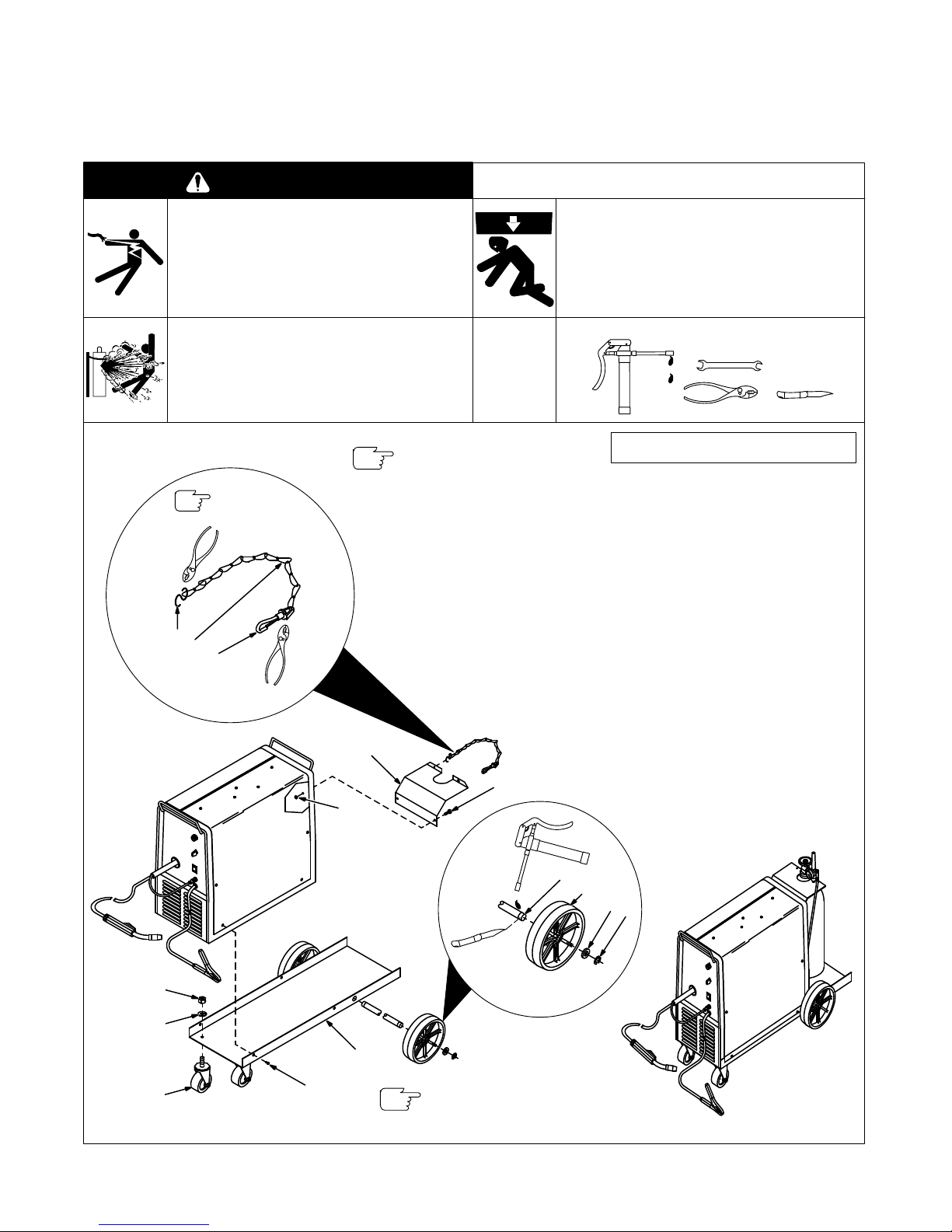
Remove and discard rear
handle of unit before installing
bottle retainer (4).
Description (Qty)
Part
No.
Item
No.
1 602
389
S-Hook (1)
2
148 188
Chain (1)
3
602 384
Snap (1)
4
147 894
Bottle Retainer (1)
5
089 800
Nut, 1/4-20 (2)
6
089 799
Screw
, 1/4-20 x 1/2 (2)
7
147 893
Axle (1)
8
090 693
Wheel, 8 in (2)
9
602 250
Washer
, 3/4 flat (2)
10
121 614
Retaining Ring (2)
11
148 110Pan (1)
12
602 154
Screw
, 1/4-20 x 1/2
self-forming (4)
13
109 318
Caster (2)
14
602 21
1 Washer
, 5/16 lock (2)
15
604 537
Nut, 5/16-18 (2)
Be sure to provide Model when ordering
replacement
parts.
5
Remove paint from axle
grooves
(7) before installing re
-
taining
rings (10).
WARNING
ELECTRIC SHOCK can kill.
• Do
not touch live electrical parts.
• Turn Off welding power source and input
disconnect
device.
• Disconnect input power conductors from
deenergized supply BEFORE moving welding
power source.
CYLINDERS can explode if damaged.
• Keep cylinders away from welding and other
electrical circuits.
•
Never touch cylinder with welding electrode.
• Always secure cylinder to running gear, wall, or
other
stationary support.
FALLING EQUIPMENT can cause injury
and damage.
• Use
proper equipment to lift unit.
• Use
lifting forks long enough to extend out opposite
side
of base.
•
Do not put any body part under unit while lifting.
miscwarn1.1 5/93
T
ools Needed:
3/8, 7/16, 9/16
1
2
3
7
8
9
10
Crimp
Items
1 & 3.
4
11
12
13
14
15
7
Figure 1-1. Installing Running Gear/Cylinder Rack
 Loading...