

Page 1
Ef
f. w/Serial Number JJ487350
April 1993
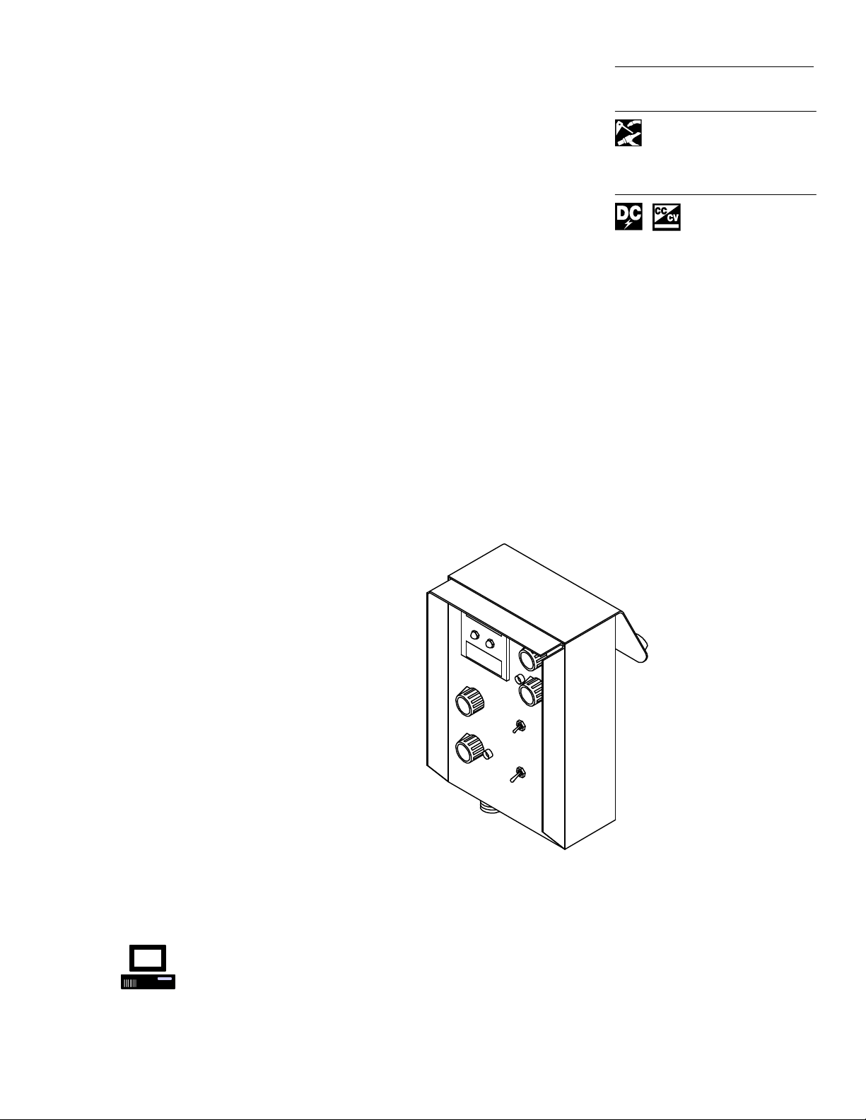
Multiprocess W
Remote Pendant Control
RPC-IP
elding
V
isit our website at
Page 2
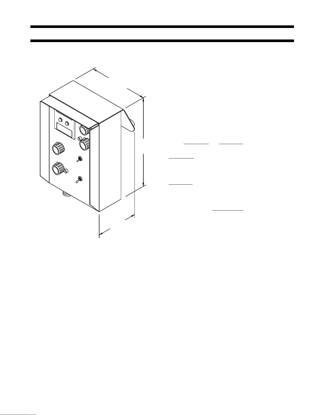
SECTION 1 – INTRODUCTION
5-3/4 in.
(141 mm)
9-3/8 in.
(238 mm)
5 in.
(123 mm)
ST-109 521-A
Figure 1-1. Dimensions
1-1. GENERAL INFORMATION AND SAFETY A. General
Information
presented in this manual and on various
bels, tags, and plates provided on this unit pertains to
equipment
and
design,
troubleshooting which should be read,
installation, operation, maintenance,
understood,
la
and
followed for the safe and ef
fective use of this equip
ment.
B. Safety
The installation, operation, maintenance, and troubleshooting of arc welding equipment requires practices
and procedures which ensure personal safety and the
safety of others. Therefore, this equipment is to be
installed, operated, and maintained only by qualified
persons
ble
Welding
in accordance with
codes such as, but not limited to, those listed in Arc
Safety Precautions Section in the welding pow
this manual and all applica
er source Owner’s Manual.
instructions specifically pertaining to this unit ap
Safety
pear throughout this manual highlighted by the signal
words
WARNING
and
CAUTION
which identify dif
levels of hazard.
WARNING
statements include installation, operation,
and maintenance procedures or practices which if not
carefully
followed could result in serious personal injury
or loss of life.
CAUTION
statements include installation, operation,
and maintenance procedures or practices which if not
carefully
followed could result in minor personal injury or
damage to this equipment.
A
third signal word,
which
need special emphasis to obtain the most ef
IMPORTANT
, highlights instructions
operation of this equipment.
1-2. RECEIVING-HANDLING
unpacking equipment,
Before
check carton for any dam
age that may have occurred during shipment. File any
claims for loss or damage with the delivering carrier.
Assistance for filing or settling claims may be obtained
from the distributor and/or the equipment manufacturer’s Transportation Department.
When requesting information about this equipment, al-
provide the Model Description and Serial Number
ways
1-3.
DESCRIPTION
This
unit is a Remote Pendant Control for the Intellipulse
-
welding
welding
tactor
power source. When properly connected to
power source this unit provides arc control, con
control, voltage/amperage control, CV/CC selec
tion, and pulse frequency selection.
-
-
-
-
ferent
ficient
-
.
the
-
-
OM-533 Page 1
Page 3
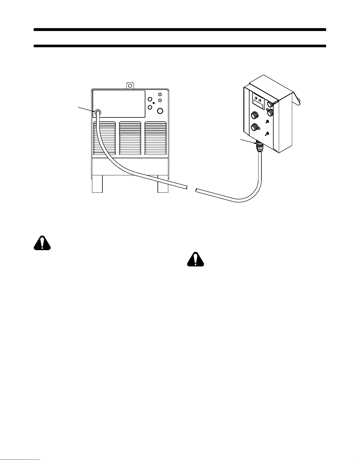
W
elding Power
Source Remote
Control Receptacle
SECTION 2 – INSTALLATION
RPC-IP
Receptacle
Figure 2-1. Power Source/Remote Control Connections
WARNING: ELECTRIC SHOCK can kill.
•
Do not touch live electrical parts.
•
Shut down welding power source, and be
sure it cannot be accidentally energized before
making remote Pendant Control connections.
•
Place CONTACTOR switch in OFF position.
2-1. WELDING POWER SOURCE REMOTE CONTROL
RECEPT
The Remote Pendant Control connects to a 17-socket
Amphenol
panel
(see OM-286). Insert 17-pin Amphenol plug
the interconnecting cable fully into the receptacle and
rotate collar clockwise.
2-2. RPC-IP RECEPTACLE CONNECTIONS (Figure 2-1)
The interconnecting cable from the welding power
source connects to a 17-pin Amphenol receptacle on
remote control. Insert the 17-socket plug from the
the
terconnecting
collar clockwise.
OM-533 Page 2
ACLE CONNECTIONS (Figure 2-1)
receptacle on the welding power source
cable fully into the receptacle, and rotate
front
from
in
2-3. 650/1000 AMPERE MODEL SELECTOR SWITCH
WARNING: ELECTRIC SHOCK can kill.
•
Do not touch live electrical parts.
•
Shut down welding power source, and dis-
connect the Remote Pendant Control before
changing position of dip switches.
ELECTROSTATIC DISCHARGE (ESD) can
damage circuit boards.
•
Put on properly grounded wrist strap BE-
FORE handling circuit boards.
•
Perform
This Remote Pendant Control is designed to be used
with either a 650 or 1000 ampere intellipulse welding
power source. A dip switch is located on circuit board
to set up the Remote Pendant Control for operation
PC5
with 650 or 1000 ampere models. The unit is shipped
the factory set up for
from
models.
dant Control for operation with 1000 ampere models:
1. Remove cover.
2. Place
-
3. Reinstall cover.
Proceed as follows to set up the Remote Pen
both dip switches in the down position for op
eration with 1000 ampere models. Place both dip
switches in up position for operation with 650 ampere models (see Figure 2-2).
work only at a static-safe work area.
operation with the 650 ampere
ST-109 782-B
-
-
Page 4
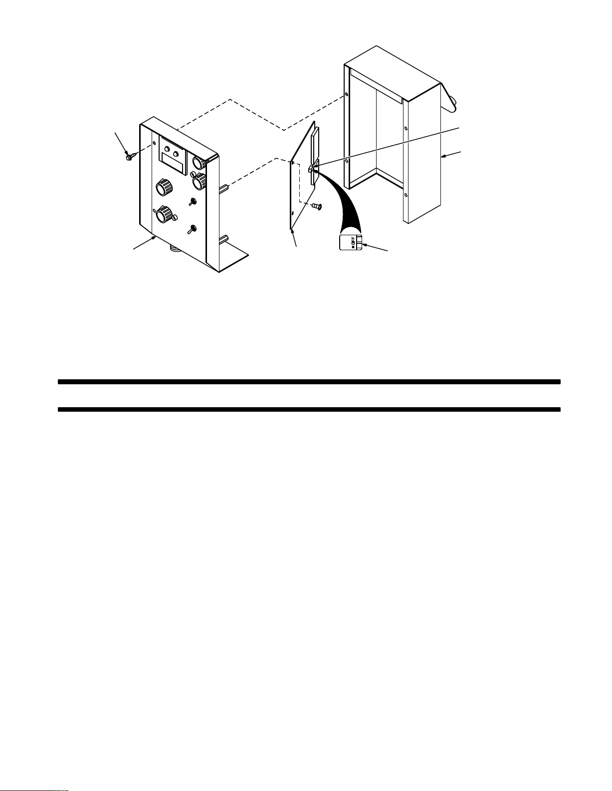
Mounting
Screws (5)
Dip
Switch
Cover
Front
Panel
Figure 2-2. Dip Switch Positions And Locations
SECTION 3 – OPERATOR CONTROLS
3-1. MODE
The Mode Selector switch allows selection of CC
(constant
put from the welding power source.
The
CC position provides a constant current output spe
cifically designed for Shielded Metal Arc (SMAW) and
Gas
T
position
(CAC-A) and gouging processes.
The
CV position provides a constant voltage output de
signed
Arc (GMAW), Flux Cored Arc (FCAW), or Submerged
Arc
(SA
SELECT
current), CV (constant voltage),
ungsten Arc (GTAW) W
OR SWITCH (Figure 3-1)
or pulsed out
elding processes. The CC
is also normally used for Air Carbon Arc Cutting
for wire feeding applications such as Gas Metal
W) Welding.
Circuit
Board
PC5
Both dip switches down for
1000 ampere model operation
Both dip switches up for
650 ampere model operation
approached. When this control is set at some value
above 0, the current begins to increase when arc voltage drops below 20 volts.
When the control is set at 10 (MAX.), the short-circuit
current
rent (see welding power source volt-ampere curve for
CC
out-of-position
is considerably
higher than normal welding cur
mode). This provides extra current for arc starting in
welds as well as for certain types of elec
trodes.
the control is set at 0 (SOFT), short-circuit current
When
is the same as normal welding current. The 0 position
provides
current characteristics associated
Tungsten Arc Welding (GTAW) process.
ST-113 509-A
-
-
with the Gas
When
pulsed output is desired for Gas Metal Arc W
ing
- Pulsed Arc (GMAW-P), place switch at the desired
eld-
number of pulses per second: 60, 90, 120 or 180.
3-2. ARC
IMPORTANT:
pilot
CONTROL AND PILOT LIGHT
The ARC CONTROL potentiometer and
light are disabled in the CV (Constant V
(Figure 3-1)
oltage) and
pulsed modes.
The ARC CONTROL potentiometer provides variable
selection of short-circuit current to suit individual welding conditions. Rotating this control clockwise causes
the current to increase as the short-circuit condition is
When the control is set at 5, short-circuit current is
approximately
higher
than normal welding current. The 5 position pro
half that of the 10 (MAX.) position but still
vides a moderate current increase for arc starting necessary
for certain types of electrodes and
applications.
Select a setting best suited for the application.
The Arc Control pilot light turns on when the Mode Se-
lector
switch is in the CC position indicating that the ARC
CONTROL is active.
IMPORTANT:
The ARC CONTROL can be adjusted
while welding.
OM-533 Page 3
-
Page 5

Voltmeter
Ammeter
Volts/Peak
Control And
Pilot Light
Mode
Selector
Switch
Ammeter
Switch
Arc
Control
Arc Control
Pilot Light
Contactor
Switch
Figure 3-1. Front Panel View
Amps/Bkgd
Control And
Pilot Light
ST-109 521-A
3-3. CONTACTOR SWITCH (Figure 3-1)
WARNING: ELECTRIC SHOCK can kill.
•
Do not touch live electrical parts.
•
Do
not touch the weld output terminals when
the contactor is energized.
•
Do not touch electrode holder (or gun wire)
and work clamp at the same time.
If
the Remote
position,
Control CONT
ACT
OR switch is in the ON
open-circuit voltage will be present at the out
put terminals whenever the welding power source
POWER switch ON button is depressed.
IMPORTANT:
on
the nameplate and throughout this manual, the
Although the term CONT
ACT
OR is used
weld
output is not switched on or off by a physical secondary
contactor;
rather
, the weld output is controlled by
solid-
state circuitry in the welding power source.
If
contactor control by means of
a wire feeder is desired,
place the Remote Control CONTACTOR switch in the
OFF
position. Open-circuit voltage will be present at the
weld output terminals whenever the gun switch is
closed.
The
OFF position is normally used with all wire feeding
processes (GMAW, GMAW-P, FCAW, SAW) and the
Gas Tungsten Arc Welding (GTAW) process. The ON
position is normally used with the Shielded Metal Arc
Welding
(SMA
W) and the Air Carbon Arc (CAC-A)
Cut
-
ting and gouging processes.
Lift end of toggle switch to change switch positions.
OM-533 Page 4
3-4. AMMETER SWITCH (Figure 3-1)
The AMMETER switch provides selection of reading
PEAK weld amperage or Average (AVG) weld amperage on the Remote Control digital ammeter.
Normally the AVG switch position is used for reading
weld amperage during Gas Metal Arc (GMAW), Flux
Cored Arc (FCAW), Submerged Arc (SAW), Shielded
Metal
Arc (SMA
W), Gas T
ungsten Arc (GTAW) W
elding
and Air Carbon Arc (CAC-A) Cutting and gouging processes.
While
welding using the Gas
Arc (GMAW-P) process, the A
Metal Arc W
elding - Pulsed
VG switch position is
used
when display of the average (background and peak)
weld amperage is desired. The AMMETER switch can
be placed in the PEAK position when display of peak
weld amperage is desired.
3-5. AMPS/BKGD CONTROL AND PILOT LIGHT (Figure 3-1)
control presets weld amperage for constant current
This
applications and background amperage for GMAW-P
applications.
the Mode Selector switch is in the
When
CC position or
one of the pulses per second positions, the AMPS/
BKGD pilot light turns on.
control is disabled
This
when the Mode Selector switch
is in the CV position.
Rotating the control clockwise increases amperage.
IMPORTANT:
The AMPS/BKGD control can be ad-
justed while welding.
Page 6

3-6. VOLTS/PEAK CONTROL AND PILOT LIGHT (Figure 3-1)
This control presets weld voltage for constant voltage
applications and peak voltage for GMAW-P applications.
the Mode Selector switch is in the
When
one of the pulses per second positions, the VOLTS/
PEAK pilot light turns on.
This
control is disabled
is in the CC position.
Rotating the control clockwise increases voltage.
when the Mode Selector switch
CV position or
SECTION 4 – SEQUENCE OF OPERATION
IMPORTANT:
justed while welding.
3-7. METERS (Figure 3-1)
The
voltmeter displays weld
of a volt while welding and preset voltage when unit is
idling.
When welding using the pulsed GMA
the meter displays peak voltage.
The ammeter displays weld amperage to the nearest
ampere
idling.
the meter displays background amperage.
while welding and preset amperage
When welding using the pulsed GMA
The VOLTS/PEAK control can be ad-
voltage to the nearest tenth
W process,
when unit is
W process,
WARNING: ELECTRIC SHOCK can kill;
MOVING PARTS can cause serious injury;
IMPROPER AIR FLOW AND EXPOSURE TO
ENVIRONMENT can damage internal parts.
•
Keep
all covers and panels in place while
erating.
Warranty is void if the welding power source is
operated
removed.
ARC RAYS, SPARKS, AND HOT SURFACES
can
hearing.
•
FUMES AND GASES can seriously harm
your health.
•
gases from the breathing zone.
WELDING WIRE can cause puncture
wounds.
•
or other personnel.
HOT METAL, SPATTER, AND SLAG can
cause fire and burns.
•
•
how to use it.
MAGNETIC
can affect pacemaker operation.
•
fore going near arc welding, gouging, or spot
welding operations.
See
the welding power source Owner’s Manual.
with any portion of the outer enclosure
burn eyes
Wear correct eye, ear, and body protection.
Use enough ventilation to keep fumes and
Do
not point gun toward any part of the body
Watch for fire.
Have a fire extinguisher nearby and know
Wearers should consult with their doctor be-
Arc W
and skin; NOISE can damage
FIELDS
elding Safety Precautions Section in
FROM HIGH CURRENTS
op
4-1. GAS METAL ARC WELDING - PULSED ARC (GMAW-P)
WARNING:
-
1. Install
2. Install Remote Control as instructed in Section 2.
3. Install
4. Wear dry insulating gloves and clothing, and wear
5. Prepare for welding as follows:
6. Depress
7. Place Mode Selector switch to desired pulses per
8. Place CONTACTOR switch in OFF position (see
9. Place
10. Preset
tion at beginning of entire Section 4 before
proceeding.
and prepare welding power source according
to its Owner’s Manual.
and prepare wire feeder according to its Own
er’s Manual.
welding helmet with proper filter lens according to
ANSI Z49.1.
a. Connect work clamp to clean, bare metal at
workpiece.
b. Select and obtain proper welding wire, and
thread as instructed in wire feeder Owner’s
Manual.
welding power source POWER switch
button.
second (60, 90, 120, or 180) position (see Section
3-1).
Section 3-3).
AMMETER switch in the desired position (see
Section 3-4).
AMPS/BKGD control to desired
amperage setting (see Section 3-5). Pilot light
should be on.
Read and follow safety informa
-
-
ON
background
OM-533 Page 5
Page 7

11. Preset VOLTS/PEAK control to desired peak voltage setting (see Section 3-6). Pilot light should be
on.
12. Make adjustments to wire feeder.
13. Turn on shielding gas supply.
14. Begin welding.
4-2. GAS METAL ARC AND FLUX CORED ARC WELDING (GMAW AND FCAW)
WARNING:
Read and follow safety informa
tion at beginning of entire Section 4 before
proceeding.
1. Install
and prepare welding power source according
to its Owner’s Manual.
2. Install Remote Control as instructed in Section 2.
3. Install
and prepare wire feeder according to its Own
er’s Manual.
4. Wear dry insulating gloves and clothing, and wear
welding helmet with proper filter lens according to
ANSI Z49.1.
5. Prepare for welding as follows:
a. Connect work clamp to clean, bare metal at
workpiece.
4. Place Mode Selector switch in CC position (see
Section 3-1).
5. Place
ARC CONTROL to desired position (see
tion 3-2). Pilot light should be on.
6. Place CONTACTOR switch in ON position (see
Section 3-3).
7. Place
AMMETER switch in A
VG (A
verage) position
(see Section 3-4).
8. Preset
-
AMPS/BKGD
control to desired weld amper
age setting (see Section 3-5). Pilot light should be
on.
9. Wear dry insulating gloves and clothing, and wear
welding helmet with proper filter lens according to
ANSI Z49.1.
10. Prepare for welding as follows:
a. Connect work clamp to clean, bare metal at
-
workpiece.
b. Select and obtain proper electrode, and insert
into electrode holder.
11. Begin welding.
4-4.
SUBMERGED ARC WELDING (SA
WARNING:
Read and follow safety informa
tion at beginning of entire Section 4 before
proceeding.
W)
Sec
-
-
-
b. Select and obtain proper welding wire, and
thread as instructed in wire feeder Owner’s
Manual.
6. Depress
welding power source POWER switch
ON
button.
7. Place Mode Selector switch in CV position (see
Section 3-1).
8. Place CONTACTOR switch in OFF position (see
Section 3-3).
9. Place
AMMETER switch in A
VG (A
verage) position
(see Section 3-4).
10. Preset VOLTS/PEAK control to desired weld voltage setting (see Section 3-6). Pilot light should be
on.
11. Make adjustments to wire feeder.
12. Turn on shielding gas supply if applicable.
13. Begin welding.
4-3. SHIELDED METAL ARC WELDING (SMAW)
WARNING:
Read and follow safety informa
tion at beginning of entire Section 4 before
proceeding.
1. Install
and prepare welding power source according
to its Owner’s Manual.
2. Install Remote Control as instructed in Section 2.
3. Depress
button.
OM-533 Page 6
welding power source POWER switch
ON
1. Install
and prepare welding power source according
to its Owner’s Manual.
2. Install Remote Control as instructed in Section 2.
3. Install
4. Install
flux system according to its Owner’s Manual.
and prepare wire feeder according to its Own
er’s Manual.
5. Wear dry insulating gloves and clothing, and wear
safety
goggles with correct filter shade according to
ANSI Z49.1.
6. Prepare for welding as follows:
a. Connect work clamp to clean, bare metal at
workpiece.
b. Select and obtain proper welding wire, and
thread as instructed in wire feeder Owner’s
Manual.
c. Select and obtain proper flux, and put into flux
system.
7. Depress
welding power source POWER switch
button.
8. Place Mode Selector switch in CV position (see
-
Section 3-1).
9. Place CONTACTOR switch in OFF position (see
Section 3-3).
10. Place
AMMETER switch in A
VG (A
verage) position
(see Section 3-4).
11. Preset VOLTS/PEAK control to desired weld voltage setting (see Section 3-6). Pilot light should be
on.
-
ON
Page 8

12. Make adjustments to wire feeder.
13. Turn on flux supply system.
14. Begin welding.
4-5. GAS TUNGSTEN ARC WELDING (GTAW)
4-6. AIR CARBON ARC CUTTING AND GOUGING (CAC-A)
WARNING:
tion at beginning of entire Section 4 before
proceeding.
Read and follow safety informa
-
WARNING:
tion at beginning of entire Section 4 before
proceeding.
1. Install
2. Install Remote Control as instructed in Section 2.
3. Install
4. Depress
5. Place Mode Selector switch in CC position (see
6. Set
7. Place CONTACTOR switch in ON position (see
8. Place
9. Preset
10. Wear dry insulating gloves and clothing, and wear
11. Prepare for welding as follows:
12. Turn on shielding gas and water supplies as appli-
13. Turn on and adjust High-Frequency unit if applica-
14. Begin welding.
and prepare welding power source according
to its Owner’s Manual.
and prepare High-Frequency unit according
to its Owner’s Manual if applicable. Scratch start
GTAW
does not require the use of external high fre
quency.
button.
Section 3-1).
ARC
light should be on.
Section 3-3).
AMMETER switch in A
(see Section 3-4).
AMPS/BKGD
age setting (see Section 3-5). Pilot light should be
on.
welding helmet with proper filter lens according to
ANSI Z49.1.
a. Connect work clamp to clean, bare metal at
workpiece.
b. Select and obtain proper tungsten electrode.
c. Prepare tungsten electrode according to weld-
ing power source Owner’s Manual, and insert
into torch.
cable.
ble.
Read and follow safety informa
welding power source POWER switch
CONTROL to MIN. (see Section 3-2). Pilot
VG (A
verage) position
control to desired weld amper
ON
-
1. Install
2. Install Remote Control as instructed in Section 2.
3. Connect compressed air supply.
4. Depress
5. Place Mode Selector switch in CC position (see
-
6. Set ARC CONTROL to desired position (see Sec-
7. Place CONTACTOR switch in ON position (see
8. Place
9. Preset AMPS/BKGD control to desired amperage
10. Wear dry insulating gloves and clothing, and wear
11. Prepare for welding as follows:
-
12. Turn on air supply.
13. Begin cutting/gouging process.
4-7. SHUTTING DOWN
1. Stop welding.
2. Depress
3. Turn
4. Turn
and prepare welding power source according
to its Owner’s Manual.
welding power source POWER switch
button.
Section 3-1).
tion 3-2). Pilot light should be on.
Section 3-3).
AMMETER switch in A
(see Section 3-4).
setting (see Section 3-5). Pilot light should be on.
welding helmet with proper filter lens according to
ANSI Z49.1.
a. Connect work clamp to clean, bare metal at
workpiece.
b. Select
OFF button.
cable.
plicable.
and obtain proper carbon electrode,
insert into torch.
the welding power source POWER switch
of
f the shielding gas and water supplies if appli
WARNING: HIGH CONCENTRATION OF
SHIELDING GASES can harm health or kill.
•
Shut off gas supply when not in use.
of
f flux
supply and compressed air supply if ap
VG (A
verage) position
ON
and
-
-
OM-533 Page 7
Page 9

SECTION 5 – MAINTENANCE & TROUBLESHOOTING
5-1. MAINTENANCE
Usage
and shop conditions will determine the frequency
and
type of maintenance. Inspect equipment as follows:
WARNING: ELECTRIC SHOCK can kill.
•
Do not touch live electrical parts.
•
Shut down welding power source, and dis-
connect
taining, or servicing unit. Power to the remote
control
ing repair or replacement of internal components.
1. Inspect interconnecting cord for damage to or
breaks in the insulation jacket, particularly at the
plugs. Repair or replace cord as necessary.
2. Remove
ture from electrical parts and cable.
5-2. TROUBLESHOOTING
WARNING: ELECTRIC SHOCK can kill.
•
•
connect
taining, or servicing unit. Power to the remote
control
ing repair or replacement of internal components.
CAUTION: ELECTROSTATIC DISCHARGE
(ESD) can damage circuit boards.
•
FORE handling circuit boards.
•
shielding carriers or packages.
•
INCORRECT INSTALLATION or misaligned
plugs can damage circuit board.
•
aligned.
EXCESSIVE PRESSURE can break circuit
board.
•
ment when disconnecting or connecting board
plugs and removing or installing board.
remote control before inspecting, main
should be disconnected before
grease
Do not touch live electrical parts.
Shut down welding power source, and dis-
Put on properly grounded wrist strap BE-
Transport circuit boards in proper static-
Perform
Be sure that plugs are properly installed and
Use
and grime from components; mois
remote control before inspecting, main
should be disconnected before
work only at a static-safe work area.
only minimal pressure and gentle move
attempt
attempt
A. General
It is assumed that proper installation has been made,
according
has been functioning properly until trouble developed.
B. Troubleshooting
Troubleshooting to be performed only by qualified persons.
-
The following information is supplied to diagnose and
-
provide
velop
Manual
source malfunctions.
Use this information in conjunction with the circuit diagram while performing troubleshooting procedures. If
the trouble is not remedied after performing these pro-
cedures, the nearest Factory Authorized Service Sta-
tion/Service Distribuitor should be contacted. In all
cases of equipment malfunction, the manufacturer’s
recommendations should be strictly followed.
Problems with this unit fall into four categories:
1. Front panel components
-
2. Circuit board PC5
-
3. Interconnecting cable
4. Welding power source.
If everything on the remote control functions except a
particular
attributed to a broken component. Replace the broken
component.
If
the problem is still present,
control
conditions occur and the welding power source was
working properly, replace PC5.
A
break in the
or
command signal between welding power source
remote
continuity is suspected.
Printed circuit board PC1 in the welding power source
sends
-
other components of the system are functioning, replace welding power source PC1 according to instructions in welding power source Owner’s Manual.
to
Section 2 of this manual, and that the unit
remedies for some of the troubles that may
in
this unit. Check welding power source Owner
for possible problems caused
switch, meter
is entirely non-functional, replace
interconnecting cable can interrupt power
control. Replace interconnecting cable
and receives signals from the remote control. If
, or control, the problem can be
replace PC5. If the remote
by welding power
de
’s
PC5. If erratic
and
if lack of
all
-
OM-533 Page 8
Page 10

SECTION 6 – ELECTRICAL DIAGRAMS
Circuit Diagram No. SB-107 993-B
Diagram 6-1. Circuit Diagram For Pendant Control
Circuit Diagram No. SB-124 223
Diagram 6-2. Circuit Diagram For Circuit Board PC5
OM-533 Page 9
Page 11

Wiring Diagram No. SC-122 538-B
OM-533 Page 10
Diagram 6-3. Wiring Diagram For Pendant Control
Page 12

SECTION 7 – PARTS LIST
Item
No.
Dia.
Mkgs.
Part
No.
Description
Figure 7-1. Main Assembly
. .
. . . . . . . . . . . . . . . . . . . . . . . . . . . . . . . . . . . . . . . . . . . . . . . . . . . . . . . .
1 108 056 CASE SECTION, front end 1.
2 109 779 CASE 1.
. .
. . . . . . . . . . . . . . . . . . . . . . . . . . . . . . . . . . . . . . . . . . . . . . . . . . . . . . . . . . . . . . . . . . . . . . . . . .
3 R6,7 603 856 POTENTIOMETER, WW 10 turn 2 watt 10K ohm 2.
. .
. . . . . . . . . . . . . . . . . . . . . . . . . . . . . .
4 S7 011 770 SWITCH, toggle SPDT 5 amp 125 volts 1.
. .
. . . . . . . . . . . . . . . . . . . . . . . . . . . . . . . . . . . . . . . . . .
5 S8 079 722 SWITCH, toggle SPDT 0.4 amp 2-4 volts dc 1.
. .
. . . . . . . . . . . . . . . . . . . . . . . . . . . . . . . . . . . . .
6 LED1-3 083 850 LIGHT, indicator - red lens 2 volts 3.
. .
. . . . . . . . . . . . . . . . . . . . . . . . . . . . . . . . . . . . . . . . . .
7 RC3 097 867 RECEPTACLE, 17 pin MS-3102A-20-29P 1.
. .
. . . . . . . . . . . . . . . . . . . . . . . . . . . . . . . . . . . . .
8 NAMEPLATE (order by model & style number) 1.
. .
. . . . . . . . . . . . . . . . . . . . . . . . . . . . . . . . . . . . . . . . . . . . . . . .
9 R8 009 156 POTENTIOMETER, carbon 1 turn 2 watt 2.5K ohm 1.
. .
. . . . . . . . . . . . . . . . . . . . . . . . . . . . . . .
10 S6 108 944 SWITCH, rotary - 0.5 amp 115 volts ac 1.
. .
. . . . . . . . . . . . . . . . . . . . . . . . . . . . . . . . . . . . . . . . . .
11 108 903 SHIELD, meter 1.
. .
. . . . . . . . . . . . . . . . . . . . . . . . . . . . . . . . . . . . . . . . . . . . . . . . . . . . . . . . . . . . . . . . . .
12 A&V 108 453 METER, DC 0-200 MV 2.
. .
. . . . . . . . . . . . . . . . . . . . . . . . . . . . . . . . . . . . . . . . . . . . . . . . . . . . . .
. . . . . . . . . . . . . . . .
. . . . . . . .
PC5 124 002 CIRCUIT CARD, pendant 1.
. . . . . . . . . . . . . . . .
. . . . . . . . . . . . . . . .
. . . . . . . . . . . . . . . .
. . . . . . . . . . . . . . . .
. . . . . . . . . . . . . . . .
. . . . . . . . . . . . . . . .
. . . . . . . . . . . . . . . .
. . . . . . . . . . . . . . . .
. . . . . . . . . . . . . . . .
. . . . . . . . . . . . . . . .
. . . . . . . . . . . . . . . .
. . . . . . . . . . . . . . . .
. . . . . . . . . . . . . . . .
108 904 ANCHOR, meter 1.
. . . . . . . . . . . . . . . . . . . . . . . . . . . . . . . . . . . . . . . . . . . . . . . . . . . . . .
. . . . . . . . . . . . . . . . . . . . . . . . . . . . . . . . . . . . . . . . . . . . . . . . .
038 785 STRIP, terminal 3 pole 1.
072 566 CONNECTOR, rect 8skt plug Amp 87159-8 1.
081 380 CONNECTOR, rect 14skt plug Amp 1-87159-3 1.
108 907 CONNECTOR, rect 13skt 1 row plug Amp 2-87499-3 2.
097 922 KNOB, pointer 4.
019 663 MOUNT, 15/16 OD x 3/8 2.
097 132 STAND-OFF, No. 6-32 x 3/8 inches 4.
094 484 STAND-OFF, No. 6-32 x 1 inch 4.
108 863 CABLE, interconnecting (consisting of) 1.
097 868 CONNECTOR, circ 17skt plug Amphenol MS-3106A-20-29S 1.
039 734 CONNECTOR, circ clamp str rlf Amphenol AN-3057-12 2.
090 263 CABLE, pwr No. 18ga 18/c (order by ft) 15ft.
097 866 CONNECTOR, circ 17 pin plug Amphenol MS-3106A-20-29P 1.
. . . . . . . . . . . . . . . . . . . . . . . . . . . . . . . . . . . . . . . . . . . . . . . . .
. . . . . . . . . . . . . . . . . . . . . . . . . . . . . .
. . . . . . . . . . . . . . . . . . . . . . . . . . .
. . . . . . . . . . . . . . . . . . . . . .
. . . . . . . . . . . . . . . . . . . . . . . . . . . . . . . . . . . . . . . . . . . . . . . . . . . . . . . .
. . . . . . . . . . . . . . . . . . . . . . . . . . . . . . . . . . . . . . . . . . . . . . .
. . . . . . . . . . . . . . . . . . . . . . . . . . . . . . . . . . . . . .
. . . . . . . . . . . . . . . . . . . . . . . . . . . . . . . . . . . . . . . . .
. . . . . . . . . . . . . . . . . . . . . . . . . . . . . . . . . . .
. . . . . . . . . . . . . . .
. . . . . . . . . . . . . . . . . . .
. . . . . . . . . . . . . . . . . . . . . . . . . . . . . . . .
. . . . . . . . . . . . . .
Quantity
.
Hardware
not available unless listed.
is common and
12
11
10
1
2
3
9
8
7
6
5
4
ST-109 521
Figure 7-1. Main Assembly
To maintain the factory original performance of your equipment, use only Manufacturer’s Suggested
Replacement Parts. Model and serial number required when ordering parts from your local distributor.
OM-533 Page 1
1
 Loading...