Gas/Current Sensing Control: 4-1/2 in. (114 mm) height, 5-1/2 in. (140 mm) width, 10-1/2 in. (267 mm) breadth, weighs 5 lbs (2.3 kg)
Spool Support Assembly: 13-3/4 in. (349mm) height, 8-3/4 in. (222mm) width, 8 12 in. (216 mm) depth weighing 6 lbs (2.7 kg)
Welding Process Support:
Robotic interface with Panasonic robots.
Collaboration on GMAW (Gas Metal Arc Welding) technology.
Digital Display Functions:
Voltage readings during welding
Indicators for wire feed rate
Amperage peaking to inductance
Connectors:
Working using the remote for disconnecting devices for welding power source RS remotes 14, 17 and 10.
A 24 pin Amphenol plug for connection to robot’s control unit.
Gas and current sensing control wiring.
Key Elements:
A burnback time setting for burn wire can be adjusted between 0 and upto 0.25 seconds.
Indication lights to show Gas flow, Contactor light, Wire Feed, Current Detector, and Arc Failure.
Use of electric current during operations and even while maintaining the machine comes with safety precautions to avoid shocks.
Warranties:
For 3 years of labor and 5 years of parts given attention for semi-automatic and automatic wire feeders, plasma-power cutting sources, and main power rectifiers.
2 years for parts and labor for engine mounted welding generators. 2
Frequently Asked Questions
Q1: For what purpose is a robot interface needed?
A1: The robot interface is responsible for linking welding power sources and panasonic robots allowing for automated welding.
Q2: What are the signs that the robot interface is attached properly?
A2: All interconnects designed for the robot interface and the power source need to be correct, In addition the control signals for the neighboring robots need to be properly connected as well.
Q3: If the unit doesn’t work what should I do?
A3: Inspect the fuses F1 for blown out ones or the circuit breaker to see if CB1 has turned off during a power trip or also ensuring whether all the wires and connections are working well.
Q4: Is it possible to configure the burnback time?
A4: In fact yes the burnback time can be modified thru potentiometer R32 present inside the device.
Q5: Indicator lights are responsible for which functions?
A5: Indicator lights are intended to show a visual evidence of gas flow, wire feed, arc detection, contactor energized and other functions of the equipment.
Q6: Please elaborate on the maintenance level needed for the robot interface.
A6: Cleaning hose and cable interfaces, component surfaces, and ensuring that label legibility is up to standards, can all be a part of scheduled maintenance.
Q7: An arc failure has occurred, what can be done to fix it?
A7: Ensure the connections to the robot control unit are established, ensure to review the welding parameters and make sure there are no faults in the welds circuitry.
User Manual
Page 1
Millerfi
November
1990
FORM:
OM-135
582B
MODEL:
Robot
(per
Interface
NSPR
8989)
OWNERS
iMPORTANT:and
the
the
safety
maintaining
by
persons
Do
ment.
Contact
power
material
trained
not
your
Read
source
throughout
this
equipment.
untrained
allow
distributor
understand
and
manual
and
experienced
If
you
used
both
This
unit
persons
do
the
with
manuals,
and
In
the
to
Install,
not
fully
entire
this
unit,
these
safe
understand
MANUAL
both
contents
before
Instructions
operationofwelding
operate,
of
with
special
Installing,
maintain
or
these
are
Instructions.
this
manual
emphasisoperating,
for
use
only
equip
this
unit.
on
or
MILLER
A
MIter
Group
P.O.
Box
Appleton,
Tel.
414-734-9821
ELECTRIC
Ltd..
Con~any
1079
WI
54912
Mfg.
USA
PRINTEDINU.S.A
Co.
Page 2
Ui
ii
LIMITED
MIg.
MIl.LER
fectsPANTYIMPLIED,
NESS-
Within
ranted
MILLER
which
followed.
MILLER
event
start
and
are
1.
2.
3.
4
-
5.
6.
Co.,
in
time
of
on
5
3
2
I
*
*
6
90
*
Inc
parts
Years
Years
Years
Year
Months
MILLERS
limited
This
sold
and
or
components
notified
be
will
honor
failure
a
that
date
follows:
Parts-3Years
main
Parts
Arc
Parts
Driven
Engines
Parts
Driven
Controllers
Coolant
Units
Welders
Banks
Transformers
..
unning
,
Options
Field
period
year
Batteries
Paris
Guns/TIC
Cutting
Controls
Wisconsin.
workmanship
periods
provide
warranty
within
the
and
Cutting
and
-
and
ear
whichever
and
WARRANTY
Appleton,
equipment
material
EXPRESSLY
IS
INCLUDING
warranty
must
MILLER
shall
such
the
as
Original
Transformer/Rectifier
PlasmaSemi-AutomaticRobots
Engine
(NOTE
MotorProcess
Water
HF
Grids
Spot
Load
SOX
-
Field
(NOTE.
warranty
one
Days
MIGPlasma
Remote
warranty
Subject
after
IN
LIEU
THE
listed
that
in
writing
equipment
power
Labor
and
Labor
Welding
are
Labor
Guns
Systems
rai
options
of
Labor
Torches
Torches
supersedes
the
to
warrants
effective
the
at
OF
WARRANTIES
below,
fail
due
within
instructions
claims
the
warranty
Labor
rectifiers
Power
Power
AutOrr~atic
Generators
warranted
era
are
the
product
is
terms
to
date
the
tune
OTHER
ALL
MILLER
such
to
thirty
on
warranted
on
time
deliveredtothe
was
Sources
Sources
Wire
separately
covered
they
greater.)
TRUE
(Equipment
all
previous
conditions
and
its
original
this
of
it
is
shipped
WARRANTIES,
MERCHANTABILITY
OF
wilt
detects
days
30)
the
warranty
equipment
periods.
Feeders
True
under
installed
are
retail
limited
by
repairorreplace
in
material
such
of
All
original
the
by
Blue
with
MILLER
below,
purchaser
warranty
MILLER.
detector
claim
listed
warranty
engine
in,
or
BLUETM
Effective
serial
a
warrantIes
MILLER
that
is
treeofde
THIS
EXPRESS
AND
any
or
workmanship.
failure,
procedures
belowinthetime
retail
purchaser,
manufacturer)
the
for
remaining
for
minimum
a
number
andisexclusive
Electric
new
WAR-
OR
FIT
war-
at
lobe
periods
~t
January
MILLERSTrue
1
2
3.
MILLERCIAUINOUSTRIAL
THEUSE
In
shall
writing
Went
chase
goods
willbeFvice
merrt
TO
ARE
LIABLE
DAMAGES
TRACT,
ANY
PANTY,
REMEDY
THEORY
OPERATIONCLUDINGFOR
FURNISHED
Somelasts,
the
cifiC
In
or
Waived,
Warranty
vary
LIMITED
1992
1,
with
no
Accessory
Replacement
,
fUrnished
Items
accessories.
trade
any
Consumable
and
relays
Equipment
that
rnent
based
and
necessary
outsideofthe
PRODUCTS
AND
the
event
at
MILLERS
be.
MILLER
by
authorized
St
an
price
Customers
at
0
B
facility
for
transportation
EXTENT
THE
THE
SOLE
FOR
TORT
EXPRESS
GUARANTY
FOR
WHICH.
ANY
PARTICULAR
states
the
or
above
limitationorexclusion
rights,
legal
Canada,
legislation
remedies
the
provides
from
province
of
other
upon
of
a
(less
,Factory
determined
as
DIRECT,
)INCLUDfNG
OR
OF
BY
in
the
exclusion
other
limitations
preface
WARRANTY
KC
or
newer)
guarantees
Kits
Parts
TM
Blue
Limited
MILLER,
by
These
items
components:
that
has
industry
MAINTENANCE
warranty
in
reasonable
PERMITTED
AND
ANY
WARRANTY
BREACH
BUT
LAW,
IMPLIED
MILLERISEXCLUDED
U.S.A.
and
than
specific
to
modified
has
been
been
improperly
standards,
maintenance,
specifications
INTENDED
ARE
AND
USERS
claim
option:
(I)
appropriate
MILLER
service
depreciation
and
risk
expense.
at
Appleton,
MILLER
by
of
costs
EXCLUSIVE
INDIRECT,
LOSS
OTHER
NOT
OR
REPRESENTATION
OF
FOR
THIS
CUSTOM
WARRANTY
PURPOSE,
do
not
of
incidental,
Other
rights
in
some
provincea
stated
as
exclusions
and
legal
province.
warranties
or
shall
Warranty
but
manufactured
covered
are
such
contact
as
by
any
installed,
or
equiprnentwhich
or
equipment
for
the
eQuipment
FOR
PERSONS
OF
WELDING
coveredbythis
or
repair:
(2)
the
cases.
(3)
station:
based
MILLERS
Wisconsin,
Therefore
will
kind
any
BY
THE
LAW,
REMEDIES.INNO
SPECIAL,
OF
PROFIT),
LEGAL
THEORY.
PROVIDED
CONTRACT
PROVISION,
OF
TRADE
OF
WITH
RESPECT
AND
allow
limitations
indirect,
not
apply
may
be
available,
may
provides
andtothe
herein,
set
out
olher
and
rights.
or
apply
Others,
by
the
manufacturers
by
tips,
cutting
other
improperly
has
EQUIPMENT
warranty,
payment
actual
option
B
at
0
no
compensation
allowed
EVENT
WHETHER
AND
TO
PERFORMANCE.
OR
MIGHT
ARISE
COURSE
ANY
TO
how
of
This
you
but
may
for
certain
extent
may
rights
may
implied.
to:
than
Operated
has
been
ANDAND
the
Or,
cost
of
use)
of
repair
MILLER
a
OR
ANY
AND
long
warranty
vary
that
not
be
PROVIDED
ANY
additional
such
noZzles.
not
USE
EXPERIENCED
exclusivewhere
of
or
SHALL
CONSEQUENTIALBASED
OF
BY
an
from
apply.
MILLER,
used
repairorreplace-
credIt
upon
OTHER
BY
ALL
implied
they
available,
expressed
not
parry
which
PURCHASE
TRAINED
replacement:
reasonable
or
(4)
upon
F
or
be
REMEDIES
INCIDENTAL
HEREIN
AS
TORT
OR
MERCHANTABILITY
DISCLAIMED
specialorconsequential
to
above
as
engines
warranty,
contactors
or
or
misused
had
reasonable
for
operation
BY
COMMER
remedies
authorIzed
for
the
return
or
replacement
authorized
reimburse.
or
HEREIN
MILLER
ON
IMPLIED
AND
LEGAL
IMPLICATION.
DEALING,
OR
FITNESS
EQUIPMENT
MILLER.
warranty
damages,
provides
state
to
warranties
may
This
Limited
but
equip-
pur
of
ser
CON-
WAR.
ANY
ape
state.
not
may
or
if
IN
in
the
BE
IN.
so
be
~1~
Page 3
ERRATA
SHEET
this
After
data
to
AMENDMENT
Amend
Section
Connections
3.
For
interface.
tk
______
WARNING:
Lockout/tagging
from
a.
Open
Locate
b.
Cut
c.
d.
Splice
Cover
e.
f.
Close
manual
appearing
SECTION
TO
3-5B.
units
used
Proceed
DoShut
not
touch
down
procedures.
fuse
box,
front
panel
lead
lead
72asclose
72
lead
splice
and
secure
was
later
ROBOT
with
Pulstar
as
ELECTRIC
live
unit,
procedures
or
access
72
at
to
lead
with
electrical
printed,
in
this
INSTALLATION
3
INTERFACE
450
follows:
electrical
welding
shutting
door.
of
F
pin
to
receptacle
77
at
front
panel
refinements
manual.
welding
SHOCK
parts.
source,
power
consist
off
and
REMOTE
REMOTE
or
tape
access
in
equipment
-
WELDING
source,
power
kill.
can
and
robot,
of
padlocking
red-tagging
17
receptacle
as
possible.
14
receptacle
other
insulation.
door.
it
line
circuit
RC16.
design
POWER
is
necessary
and
disconnect
disconnect
breaker
RC13
pin
or
D.
occurred.
SOURCE
to
change
input
switch
other
disconnecting
sheet
This
CONNECTIONS:
internal
power
in
employing
open
connections
position,
lists
exceptions
REMOTE
lockouVtagging
removing
device.
in
the
17
robot
fuses
a
Add
a
CAUTION:
See
Figure
CAUTION:
See
Be
sure
welding
3-7.
DVC
Figure
WELDING
welding
power
Voltage
INCORRECT
DIP
switch
3-7
power
source
Control
is
DVC
for
POWER
source
Owners
Board
DVC
factory
DIP
SOURCE
DIP
BOARD
set
for
switch
main
control
Manual
Switch
operation
setting
may
board
for
modification
Setting
DIP
SWITCH
with
when
not
Label
Delta
using
respond
has
been
POSITION
weldfi
another
with
output
modified
procedure.
can
451
welding
welding
corresponding
use
a
equipment
power
source.
0
to
cause
power
to
+
source.
to
10
volt
malfunction.
set
value.
command.
Page 4
DVC
SWITCH
S2
SETTINGS
Si
Add
switch
DIP
voltage
ling
another
Section
welding
3-10.
and
Si
output
SETTING
S2
at
power
on
voltage
a
welding
source,
DELTAWELD
DELTAWELD
DELTAWELD
MAXTRON
MAXTRON
XMT200/300
ARC
SHOPMASTER
DIMENSION
On
O
On
DIP
control
power
proceed
300,
450
PAK35O
For
Optional
For
Optional
Figure
SWITCHES
board
source.
300
451
651
400
3-7.
follows:
as
400
300
Hot
ON
PCi
To
1
ON
ON
ON
Soft
Start.
Start.
DVC
VOLTAGE
allow
change
2
0
0
ON
DIP
Switch
setting
factory
Turn
1
ONON
ON
ON
ON
Off
Setting
CONTROL
the
set
position
2
ON
ON
ON
ONON
Si
-3.
proper
3
ON
Label
BOARD
command
DIP
of
4
ON
ON
ON
S~15o864A
5
ON
ON
ON
ON
ON
PCi
signal
switches
voltage
from
a
for
level
Deltaweldfi
control
451
to
a
1.
2.
3.
4.
Add
SOURCE
If
the
number
WARNING:
Do
Shut
not
touch
down
tagging
Lockout/tagging
from
fuse
ELECTROSTATIC
Put
on
properly
Transport
Perform
Loosen
Locate
trol.
Set
power
Close
Section
robot
screws
voltage
position
source.
and
3-11.
interface
JJ400026,
secure
ELECTRIC
live
electrical
unit,
welding
procedures
procedures
or
box,
shutting
DISCHARGE
grounded
boards
circuit
work
only
securing
control
DIP
of
VOLTAGE
control
proceed
board
switches
access
to
is
as
SHOCK
before
off
at
static-safe
a
front
PCi
door.
CONTROL
be
used
follows:
parts.
power
setting
consist
and
wrist
in
proper
access
Si
and
kill.
can
source,
and
DIP
switches.
of
padlocking
red-tagging
strap
can
BEFORE
(ESD)
static-shielding
work
area.
and
door,
in
with
lower
S2
according
BOARD
an
early
left
portion
wire
feeder,
line
circuit
breaker
damage
handling
carriers
door.
open
of
component
label
to
MODIFICATION
Deltaweld
model
and
disconnect
or
circuit
boards.
circuit
or
inside
FOR
450
disconnect
switch
other
disconnecting
boards.
packages.
mounting
and
unit
EARLY
650
or
welding
input
in
open
panel
Figure
MODEL
power
position,
device.
inside
3-7
for
power
employing
removing
interface
robot
appropriate
WELDING
source
prior
lockout/
fuses
con
welding
POWER
serial
to
OM-135
5828
Page
2
Page 5
a
WARNING:
Do
not
Shut
tagging
Lockout/tagging
from
fuse
ELECTRIC
touch
down
unit,
procedures
or
box,
live
procedures
ELECTROSTATIC
i
Put
on
properly
Transport
Perform
circuit
work
only
SHOCK
electrical
welding
before
shutting
off
DISCHARGE
grounded
boards
static-safe
at
a
parts.
power
making
consist
and
wrist
in
proper
kill.
can
and
can
BEFORE
wire
board
circuit
damage
handling
source,
circuit
of
padlocking
red-tagging
(ESD)
strap
static-shielding
work
area.
feede~
modifications.
line
and
disconnect
breakerorother
circuit
carriers
boards.
circuit
or
packages.
disconnect
switch
disconnecting
boards.
input
in
open
power
employing
position,
device.
Iockout/
removing
fuses
IMPORTANT:
control.
1.
Loosen
2.
Locate
trol.
3.
Mark
4.
Mark
5.
Note
6.
Place
7.
Locate
8.
Use
J6,
J4,
9.
Apply
10.
Apply
11.
Reinstall
12.
Reconnect
Receptacle
board
PCi
trol
A
customer-supplied
screws
voltage
and
and
position
circuit
jumpers
a
sharp
and
small
a
sealant
a
RC1
securing
control
disconnect
disconnect
of
board
tool
J8.
amount
circuit
marked
6
leads
follows:
as
circuit
Ji
to
coating
board
76,
cord
front
access
PCi
board
from
leads
plugs
board
on
a
stationary
thru
J8onsurfaceofboard
remove
of
solder
over
into
leads
and
and
77,
from
and
sealant
all
in
unit
plugs
78
voltage
to
jumper
must
(Miller
door,
in
lower
PCi.
remove
work
coating
bridge
its
original
to
be
#042562)isrequired
and
left
portion
control
from
surface
from
all
the
foil
locations.
door.
open
of
component
PCi.
board
unit.
that
so
(see
Figure
jumper
component
locations,
padsatjumper
position.
appropriate
changedatplug
locations.
PLG1
to
3-8).
4
connect
mounting
side
and
remove
Ji,J3,
connected
the
is
J5,
welding
facing
and
to
power
inside
panel
up.
foil
jumper
J7.
receptacle
source
robot
between
RC1
to
interface
pads
on
voltage
the
weld
con
at
con
J2,
IMPORTANT:
1.
Locate
2.
Mark
window
3.
Bend
4.
Insert
Lead
a.
Lead
b.
c.
5.
6.
Lead78
Reconnect
Close
Figure
Add
See
and
and
remove
side
on
locking
lead
contacts
76
to
77
to
to
and
secure
3-8.
Jumper
receptacle
disconnect
leads
of
plug
tabs
on
plug
opening
opening
plug
plug
opening
PLG14
plug
access
Locations
RC1
plug
to
lead
into
to
pin
PLG14
and
77,
76,
bend
down
contacts
follows:
as
plug
10.
8.
9.
receptacle
door.
On
Voltage
designations
from
receptacle
from
78
locking
Out
RC1
50
thatthey
on
Control
plug
tab,
voltage
etchedoncircuit
RC1
on
voltage
PLG1
4
inserting
by
and
Board
pull
secure
control
contact
contacts
board
PCi
board
to
identify
control
end
of
attachedtolead
inserted
when
PCi.
board
a
small,
plug
PCi.
from
into
openings.
flat-tip
screwdriver
plug.
plug.
OM-1355828Page3
into
Page 6
Ret.
SD148
322
AMENDMENT
Amend
Delete
This
Amend
Amend
Diagram
Diagram
diagramnolonger
Diagram
Diagram
TO
7-1.
7-2.
7-3.
7-4.
SECTION
Circuit
Circuit
applies
Circuit
Circuit
Figure
7
Diagram
Diagram
Diagram
Diagram
3-8.
Jumper
ELECTRICAL
For
For
effective
For
For
Locations
Robot
Voltage
with
Serial
Motor
Interface
DIAGRAMS
Interface
Board
No.
Control
Board
On
(see
PCi
KC231
Board
PC3
Voltage
page
859
PC2
(see
Control
8
on
(see
page
Board
Errata
this
pages
9onthis
6
and
Errata
PCi
Sheet)
7
on
Sheet)
this
Errata
Sheet)
OM-135
582B
Page
4
Page 7
AMENDMENT
TO
SECTION
8
PARTS
LIST
Amend
.
.
.
.
.
.
.
.
20-
.
20-
.
20-
.
20-
.
20-
.
20-
.
20-
.
20-
.
20-
.
21-
.
21-
.
21-
.
19-
19-19-19-
19-
19-19-19-
Parts
.
..
.
..
PLG25
.
.
.
.
List
Dia.
Mkqs.
CR4
PCi
PC4
RC13
follows:
as
028
.
..
049079844
048029
026202
137695
.
.
.
.
..
109
.
.
072292
Part
No.
Added
027811
117
Added
111
116
964
111
Added
Added
291
970
836
768
122
123
Replaced
With
028
.
.
095
.
.
048
.
.
079844
.
.
027811
.
.
048029
.
.
026202
.
.
148320
.
.
+149
.
117
.
.
094
.
.
141
.
.
134
073739
Deleted
.
.
152
.
.
079
079739
154
..
141
.
.
605941
.
.
291
521588
339037480
162
731
370534
098
700
Description
CAPACITOR,
..
RELAY,
..
BRACKET,
..
SPRING,
..
SOCKET,
..
CLIP,
..
..
..
..
..
..
..
..
..
..
..
..
.
.
..
..
..
(qty
DIODE,
CIRCUITCIRCUIT
HOUSING,
RECEPTACLE,
HOUSING
TERMINAL,
..
CLAMP,
.
.
CLAMP,
HOUSING
TERMINAL,
..
CLAMF~
..
SHAFT,RING,
(mci.
retaining
w/hub
WASHER,flatstl.64OIDx1.OOD
w/hub
(md.
24VDC
end
mtg
(qty
(qtychg)chg)
(qty
chg)
CARD,CARD,
term
PLUG
cable
(now
PLUG
strain
spool
&
spindle
&
spindle
(qty
chg
relay
chg)
(added
(qtychg)
meter
hdr
14
pin
&
PINS,
male
strain
md.
w/housing
&
SOCKETS,
female
relief
support
.625shaftx
ext
4PDT
2skt
1
&
dia.
mkg.
D4)
w/KB113874)
(Eff
MS-3102A-20-27P
(consisting
pin
relief
17
sz
18-14
16
sz
plug
(consisting
18-14
wire
.O5Othk
lskt
sz
17
assy)
assy)
chg)
&
pins)
is
(C2-4
now
(Effw/KC217109)
of)
wire
of)
Quantity
C6-10)
5
.
11
2
2
2
3
11
1
1
.
1
14
2
1
14
2
1
1
1
**First
+Eff
w/KB1
BE
SURE
represents
digit
13874.
TO
Parts
PROVIDE
page
on
page
MODEL
no
digits
27
AND
following
not
may
NSPR
dash
represent
NUMBER
represent
actual
board.
WHEN
item
no.
ORDERING
REPLACEMENT
PARTS.
OM-135
582B
Page
5
Page 8
fi~
'111_
_nrL
ALL
ALL
COM)OJ
H
WAVEFOPIlS
VOLTAGES
POINT
WITH
RESPECT
AT
MEASIJPED
J.
TO
300
EXCEPT
IPW-MOTOP
WITH
POINT
~4.
PESPECT
~I(.
PUNNING
MEASURE
TO
fi
ft_ill
fi~
W
S
V
A
L~i
~
052
R
V
A
s
J
B
OM-135
582B
Page
3V.
7-3.
Diagram
6
Circuit
Diagram
For
Motor
Control
Board
PC2
Page 9
M
D
C
F
P
150
C??
Circuit
Diagram
No.
OM-135
SD-083
5828
388-B
Page
7
Page 10
H
H
/0/
L
L
/00
K
J
H
0
F
E
o
C
88
000
K
/2
0000
U
0
J8
H
0
0
84
0
0
0
JI
F
7572
000
GE
75
C
0
0
J2
B
4
0
0C
I
A
ITO
2T
I
PC
657
8910
18311
2
PC9
3
2
G
J
K
Ill?
E
CO
IETEP
v~~t
I
I
I
I
CIS4TP12..
14
liii
ID)
PC4
AiPS/
1111
DO.~tTA#~
p5~(
I
I
I
JO
52
5
69
68
78
p
76
/1
J5
65
12
5252
U
80*80
RCI/PL0I4
RC6/PLG2S
124
VTLTAGE
42
1AOOTER
FEEOBAO<
~
>>~<
1>>
B>)
~6S
1-18
/5
,k19
A~
9dB
RCI9
IS)
ON
A-H
AA-AIJ
BOARD
PC3
INTERFA~
Y
S
U
230
SPEED
54
FEED
SC-i
WIRE
No.
Diagram
S.
E
C
-
B
P
-
P
A
-
PC6
J
A
F
A
A
~\
~
RC9
10
CI3ITROI_
3
GAS
2
AOl
I
~\
184
STICK
H
v____v____v_.J
9d00/REGSO
~
SENRE/WIRE
0
ON
A-S
IIJCH
___________
u
I
j<)(L
/04
1/05
~
2
<
c<
B
PCI
SENSE
ARt/T~Lu
Circuit
KC231859
No.
Serial
CS,~jC41j~,
With
Effective
C
~
K
P
H
~
~
P
p
~
S
L
N
a
Interface
C,
Robot
For
Diagram
P
A
G
Circuit
7-i.
Diagram
vu
r
VI3T5
ARC
0
A
F
H
8)(0ID
5
PCI
C
-I
H
B
A
0
Li
C
RCI6
~
C.)
0
-o
56
B
on
99
9
H
7
PCI
Page 11
POIJER/GROUHO
RI
UI
NETS
i~GND8IS)
8.5140
I6~ISU
FOR
CHIPS
Diagram
7-4.
Circuit
Diagram
For
Interface
Board
Circuit
PC3
Diagram
No.
SB-141
311-A
OM-135
5828
Page
9
Page 12
Page 13
RECEIVING-HANDLING
OM-135
5829-11/90
Before
age
claims
unpacking
that
may
for
loss
Assistance
from
the
distributor
ers
Transportation
When
requesting
provide
ways
Number.
Section
SECTION
SECTION
equipment,
occurred
have
or
damage
for
filingorsettling
and/or
Department.
information
the
Model
Description
No.
-
1
SAFETy
1-1.1-2.
General
Safety
2
SPECIFICATIONS
check
during
with
claims
the
equipment
about
Information
Alert
carton
shipment.
the
delivering
may
this
and
PRECAUTIONS
Symbol
for
any
dam-
File
carrier.
be
obtained
manutactur-
equipment,
Serial
or
Style
TABLE
AND
And
Safety
And
Signal
any
al
OF
Use
tion
mation
Model
Senal
Date
CONTENTS
SIGNAL
Words
the
following
Serial
and
located
is
_______________________________
or
Style
of
Purchase
WORDS
or
No.
spaces
Style
the
on
____________________
_____________________
to
record
Number
data
the
of
your
cardorthe
Page
Model
unit.
Designa~
The
nameplate.
No.
1
1
infor
SECTION
SECTION
2-1.
3INSTALLATION
3-1.3-2.3-3.3-4.
3-5.
3-6.3-7.3-8.3-9.
4-
4-1.
4-2.
4-3.
4-4.
4-5.
4-6.4-7.
Amps/lnductanc~
Description
Site
Selection
Equipment
Gas/Current
Voltage
RobotRobot
Arc
Welding
Burnback
OPERATOR
Power
Jog
Purge
Voltmeter
Wire
Indicator
Sensing
Interface
Interface
Failure
Wire
Switch
Push
Push
Speed
Lights
Control
Buttons
Installation
Sensing
Control
Connections
Welding
Robot
Terminal
Light
Installation
CONTROLS
Button
Meter
Meter
Interconnections
Power
Control
Strip
Source
Unit
Connections
Connections
Connections
1
2
233
4
4
5
66
77
777
77
SECTION
5-1.5-2.
5
SEQUENCE
Input
Signals
Output
OF
From
Signals
OPERATION
Robot
From
Robot
Control
Interface
Unit
8
8
Page 14
Section
SECTION
No.
MAINTENANCE
6
&
TROUBLESHOOTING
Page
No.
SECTION
SECTION
6-1.
6-2.
6-3.
6-4.6-5.
6-6.6-7.
7-
DiagramDiagram
Diagram
DiagramDiagramDiagramDiagram
-
8
FigureFigureFigure
FigureFigure
Figure
Routine
OverloadReinstallation
Display
Circuit
Maintenance
Protection
Of
Board
Board
PC4
Handling
Troubleshooting
Use
Of
Indicator
ELECTRICAL
7-1.
PARTS
8-1.
8-2.8-3.8-4.8-5.
8-6.
7-2.
7-3.
7-4.
7-5.
7-6.
7-7.
Circuit
Circuit
CircuitCircuit
Circuit
Circuit
CircuitCircuitCircuitCircuitCircuitCircuit
Circuit
DiagramDiagram
Diagram
Diagram
DiagramDiagram
Diagram
LIST
Card,
Card,
Card,
Card,Card,
Card,
Hub
Meter
Lights
DIAGRAMS
Voltage
MotorInterface
Meter
Interface
Wire
Assembly
Check
Precautions
For
Troubleshooting
For
Robot
For
Voltage
Motor
Control
For
Interface
For
Display
For
Arc
Failure
For
Touch
Control
Speed
PC4
Touch
Digital
PC3
PC5
PC6
Interface
Board
PCi
Board
Board
Board
PC4
Board
Sense/Wire
PCi
PC2
PC2
PC3
PC5
Stick
Board
PC6
....
89
9
9
10
11
13
14
15
16
1717
1818
222426
272829
Table
Table
2-1.
Specifications
6-1.
Troubleshooting
LIST
OF
CHARTS
AND
TABLES
1
12
Page 15
SECTION
1
-
SAFETY
PRECAUTIONS
AND
SIGNAL
WORDS
GENERAL
1-1.
AG
Information
bels,
design,troubleshooting
followed
B.
Safety
The
installation,
shooting
and
procedures
safety
stalled,
Sons
codes
Section
of
Power
ing
Manual.
I
enera
presented
and
tags,
installation,
for
the
of
arc
of
others.
operated,
in
accordance
such
as,
1
Source
plates
which
safe
operation,
welding
which
Therefore,
but
Safety
INFORMATION
in
this
the
on
operation,
should
effective
and
equipment
ensure
maintained
and
with
this
limited
not
Rules
in
the
welding
AND
manual
unit
andonvarious
pertains
maintenance,
be
read,
of
use
maintenance,
requires
personal
this
equipment
only
manual
to,
For
and
those
Operation
power
SECTION
SAFETY
to
equipment
understood,
this
equipment.
and
trouble-
practices
and
safety
is
be
to
qualified
by
all
applicable
listedatthe
Of
Weld-
Arc
source
Owners
1-2.
The
Ia-
used
tify
and
and
the
in-
per-
end
2
SPECIFICATIONS
~
IMPORTANTnecessary
ment.
SAFETY
WORDS
following
throughout
different
levels
This
wordstiontothe
WARNING
practices
ous
personal
CAUTION
practices
personal
for
ALERT
safety
this
safety
WARNING
safety
which
which
injury
statements
the
most
SYMBOL
alert
symbol
manualtocall
hazard
of
alert
statements
injury
statements
and
symbol
and
statements.
must
or
be
must
or
damage
identify
efficient
AND
and
signal
attention
used
of
to
life.
this
instructions.
with
procedures
to
procedures
equipment.
special
is
CAUTION
identify
be
followed
loss
identify
followedtoavoid
special
operation
SIGNAL
words
iden
to
and
the
signal
call
to
atten
seri
avoid
minor
instructions
of
this
equip
are
or
or
Component
Robot
Gas/Current
Sensing
Spool
Assembly+
Add
2-1/4
*Add
7/8
2-1.
DESCRIPTION
The
robot
Panasonic
a
Maxtron,
provides
Interface
Control
Support
in.
(57
in.
(22
mm)
interface
robot
Pulstar
or
digital
display
mm)
for
control
and
450
Height
22-1/2
(572
4-1/2
(108
13-3/4
(349
for
brake
front
panel
is
designed
Arc
an
welding
of
weld
in.
mm)
in.
mm)
in.
mm)
resistor.
knob.
to
Pak
350,
source.
power
volts,wire
Table
Dimensions
Width
16-1/2in.
(419
5-1/2
(140
8-3/4
(222
interface
Deltaweld,
This
feed
speed,
2-1.
SpecIfications
mm)
in.
mm)
in.
mm)
+Spool
and
with
unit
The
and
These
using
Depth
6~1/4in.*
mm)
(159
10-1/2
(267
(216
peak
gas/current
current
the
in.
mm)
in.
8-1/2
mm)
Support
amperage
sensing
components
Metal
Gas
without
or
sensing
reed
function
Arc
Net
lbs.
38
kg)
(17
5
lbs.
(2.3
kg)
lbs.
6
(2.7
kg)
optional
inductance.
wire
control
relay.
with
Welding
Weight
Total
reel.
contains
the
robot
(GMAW)
Ship
61
(27.7
the
gas
system
process.
lbs.
kg)
valve
when
OM-135
582
Page
1
Page 16
SITE
3-1.
Select
2.
3.
4.
5.
6.
7.
8.
9.
1.
Correct
Shielding
Water
Adequate
No
A
Proper
cold
Proper
Adequate
wrapperfunctions.
an
flammables
clean
Mounting
the
cure
2-1
Table
EQUIPMENT
3-2.
A.
Supplied
The
following
1.
installation
Weld
Cord
quires
SELECTION
installation
input
power
gas
supply
ventilation
and
dry
temperature
airflow
space
for
installation,
holes
provide
system
gives
components
overall
Equipment
equipment
Control
and
Motor
which
site
supply
supply
(if
around
or
(if
applicable)
and
area
that
unit
to
open
the
dimensions.
INSTALLATION
is
supplied
assembly:
with
Gas/Current
Cord
SECTION
provides
unit
(see
applicable)
fresh
air
supply
avoids
and
extremes
remove
maintenance,
capability
in
to
a
permanent
standard
as
Sensing
the
following:
nameplate)
of
heat
cover
and
repair
install
and
location.
and
Control
3INSTALLATION
3.
4.
5.
C.
Obtain
as
or
and
se
re
necessary
ture
Gas/Current
onto
D.
The
Removeinstall
1.
2.
3.
4.
The
interconnecting
not
are
they
welding
OneCurrent
Welding
tact
ment.
operations.
weld
output
Sensing
wire
the
weld
Equipment
appropriate
and
for
equipment
Sensing
structures
Installation
Hub
hub
assembly
the
hub
follows:
it
as
Remove
Align
selected
support
brake
Reinstall
until
Install
hex
keyway
holeinhub
depends
washers
hex
a
slightwelding
caught,
cable
control.
be
must
control
Installation
mounting
mounting
installation.
control,
in
the
welding
(Figure
is
supplied
assembly
nut
from
and
insert
on
are
properly
nut
onto
felt
is
drag
wire
according
cords
must
pinched,
must
be
routedsothat
or
other
any
brackets
hardware.
Secure
and
all
area.
3-1)
with
the
from
the
shipping
end
of
hub
hub
support
spool
while
Hole
seated
shaft.
turning
to
support.
wire
support
be
routed
strained
or
routedtothe
it
does
grounded
or
adapter
Prepare
weld
other
equipment
robot
interface.
carton,
in
shaft
Be
the
shaft.
hub.
support
selection
size.
Tighten
hub.
Section
3-8.
that
so
during
Gas/
not
con
equip
plates
struc
control,
and
through
in
hub
the
sure
hex
nut
2.
Gas/Current
Hub
3.
4.
5.
and
Spindle
ft.
10
(3
Support
m)
Interconnecting
6.
lOft.
(3m)
7.
B.
When
ft.
10
(3
m)
Equipment
deciding
lowing:
1.
The
equipment
of
pable
2.
The
equipment
can
ing
equipment
OM-135
supporting
lead
be
located.
optional
582
Page
Sensing
Spindle
Assembly
Weld
Control
Cords
Gas
Hose
Voltage
Location
on
lengths
will
Sensing
equipment
must
the
of
limit
the
Some
extension
distributor).
2
Control
location,
be
mounted
weight
the
cords
area
cords
cords
Welding
Cord
to
of
the
supplied
in
which
be
can
(check
Power
consider
structure
a
equipment.
with
the
equipment
extended
with
Source
thefol
ca
the
us
by
welding
Hub
Figure
Hub
Assembly
Support
Shaft
3-1.
Hub
Assembly
Washer
Hub
Installation
Hex
Nut
Support
SA-126
870
Page 17
3-3.
a
GAS/CURRENT
CONNECTIONS
down
and
ELECTRIC
touch
disconnect
WARNING:
Do
not
Shut
robot,
lockout/tagging
connections.
Lockout/tagging
line
ing
moving
red-tagging
ing
disconnect
fuses
circuit
device.
SENSING
(Figure
live
electrical
unit,
welding
procedures
procedures
switch
from
fuse
breaker
CONTROL
3-2)
SHOCK
input
before
in
box,
or
parts.
power
power
consist
open
or
shutting
other
INTER
kill.
can
source,
employing
making
of
padlock
position,
off
disconnect
and
inter
re
and
A.
Robot
Connections
1.
Align
receptacle
threaded
2.
Align
receptacle
and
rotate
B.
Gas/Current
tions
1.
Align
into
matching
control,
ing
wise.
Interface
keyways,
RC9
collar
keyways,
RC16
threaded
keyways,
and
Gas/Current
insert
14-pin
on
robot
clockwise.
fully
insert
16-pin
on
gas/current
collar
Sensing
insert
Control
14-pin
receptacle
rotate
threaded
Amp
interface,
Amp
fully
plug
RC7
on
Sensing
into
plug
and
into
plug
sensing
clockwise.
Motor
from
motor
gas/current
collar
fully
Control
matching
rotate
matching
control,
Connec
cord
sens
clock
Gas/Current
Control
Volts
115
Control
SensIng
Receptacle
14-PIn
AC/Contactor
Receptacle
RC9
RC13
2.
Align
control
from
motor,
wise.
C.
Weld
For
Electrode
from
welding
minal,
through
drive
wire
terminal
(see
location).
D.
Gas
Connections
Connect
supplied)
ing
to
must
at
3-4.
hose
control.
on
fitting
be
accurately
the
source.
VOLTAGE
3-2
at
And
WARNING:
a
robot,
lockout/tagging
connections.
Lockout/tagging
ing
moving
red-tagginging
keyways,
cord
into
and
Cable
Connections
Positive/Reverse
power
the
gas/current
assembly,
Motor/Drive
from
gas
source
gas
Connect
gas/current
controlled
SENSING
3-3)
Do
not
touch
Shut
down
and
disconnect
line
disconnect
fuses
circuit
device.
insert
14-socket
matching
threaded
rotate
free-hanging
plug
collar
Polarity,
source
POSITIVE
sensing
and
connect
Assembly
cable
Owners
regulator/flowmeter
IN
to
hose
gas
sensing
ELECTRIC
live
unit,
welding
procedures
procedures
switch
from
fuse
breaker
on
fitting
from
wire
control.
a
by
regulator/flowmeter
CONNECTIONS
SHOCK
electrical
input
parts.
power
power
before
consist
in
open
or
box,
or
gas/current
other
from
receptacle
fully
route
weld
output
control,
weld
to
Manual
(customer
drive
assembly
The
gas
(Figures
kill.
can
source,
employing
making
of
padlock
position,
shutting
disconnect
motor
clock
cable
to
cable
sens
inter
off
ter
the
for
flow
and
re
and
There
ing
proper
are
control
cord
Figure
several
interconnections.
for
3-2.
cords
the
following
Side
Right
supplied
Examine
connections.
View
for
gas/current
and
TG-tt9
select
sens
646
the
1.
2.
3.
Align
keyway,
ceptacle
threaded
Connect
nalonthe
3-3.
Connect
RC12
collar
lead
wire
lead
insert
fully
with
drive
with
4-socket
robot
on
clockwise.
terminal
ring
assembly
clamp
plug
interface,
to
as
to
workpiece.
into
weld
shown
OM-135
matching
and
rotate
cable
termi
in
Figure
582
Page
re
3
Page 18
Nut
3-6.
ROBOTINTERFACE-ROBOTCONTROLUNIT
CONNECTIONS
(Figures
3-2
And
3-4)
Sensing
Lead
TerminalLocation
Figure
ROBOT
3-5.
SOURCE
There
are
the
tween
amine
and
nections.
A.
REMOTE
1.
Align
receptacle
threaded
2.
Align
ceptacle
threaded
B.
REMOTE
1.
Align
receptacle
threaded
2.
Align
ceptacle
thread
C.
REMOTE
1.
Align
receptacle
threaded
2.
Align
on
collar
If
the
welding
switch,
though
REMOTE
OM.135
Ring
3-3.
Voltage
three
robot
select
14
keyway,
collar
keyway,
on
collar
17
keyway,
collar
keyway,
on
collar
10
keyway,
collar
keyway,
the
welding
clockwise.
fully
be
connections
582
power
sure
17
receptacles.
Page
Sensing
Drive
INTERFACE
CONNECTIONS
cords
supplied
interface
the
proper
Connections
insert
RC13
on
fully
insert
welding
fully
Connections
insert
RC16
on
fully
insert
welding
clockwise.
fully
Connections
insert
RC15
on
fully
insert
power
source
the
switch
made
are
4
Connections
Assembly
for
and
welding
cords
14-socket
robot
clockwise.
14-pin
power
clockwise.
17-socket
robot
clockwise.
17-pin
power
10-socket
robot
clockwise.
into
plug
source,
is
equipped
in
is
to
Cable
Location
WELDING
power
the
plug
into
plug
into
plug
rotate
14
position,
REMOTE
3-2)
source.
following
into
and
matching
and
into
and
matching
and
into
and
receptacle
with
(Figure
interconnections
for
interface,
plug
source,
interface,
plug
source,
interface,
matching
and
the
both
Lug
TA-109
093
At
Wire
POWER
be
Ex
con
matching
rotate
re
rotate
matching
rotate
re
rotate
matching
rotate
threaded
14/17
a
even
14
and
a
1.
Obtain
supplied).
2.
Connect
ate
3.
Align
ceptacle
lar
4.
Route
cord
The
input
RC17
are
as
Socket
Socket
Socket
Socket
Socket
Socket
Socket
Socket
Socket
Socket
Socket
Socket
Socket
Socket
Socket
Socket
WARNING:
Do
not
Shut
robot,
touch
down
and
ELECTRIC
unit,
disconnect
lockout/tagging
connections.
Lockout/tagging
line
device.
a
proper
conductors
keyway,
on
clockwise.
and
the
to
and
output
means
Digital
ets
Arc
Touch
Current
Weld
Circuit
A;
point.
Gas
Circuit
H,K,M,
Touch
Circuit
H,
Wire
Circuit
H,
Wire
Circuit
H,K,M,
VoltageVoltage
disconnect
fuses
from
circuit
cord
in
plug.
insert
robot
interface,
connect
robot
control
signals
of
the
common
and
C,
B,
failure
Sense/Wire
detect
start
Common
all
circuit
valve
common
P,
Sense/Wire
common
K,M,P~
inch
positive
common
K,M,P,
inch
negative
common
P,
control
control
input
ingmovingred-tagginging
sockets
fully
by
follows:
A:
B:
C:
G:
H:
J:
K:
L:
M:
N:
P:
0:
R:
S:
T:
U:
SHOCK
live
electrical
welding
input
procedures
procedures
switch
fuse
box,
breakerorother
and
24-pin
end
at
one
24-pin
conductors
robot
output
unit.
at
for
G.
plug
and
the
sockets
interface
output
signal.
stick
output
input
signal.
for
Sockets
voltages
signal.
for
input
R
and
stick
for
input
A
and
(+)
for
input
R.
and
()
for
andR
input
positive
connection.
wiper
parts.
power
power
before
consist
in
open
or
shutting
Amphenol
of
cord
into
rotate
at
remaining
control
signals
output
signal.
H,
referenced
signals
inputsignals
input
signal.
signals
input
signal.
signals
connection.
(+)
kill.
can
source,
employing
making
position,
inter
of
padlock
off
disconnect
plug
to
appropri.
matching
threaded
end
of
receptacle
circuitry
Sock
at
signal.
K,M,P,
to
at
Sockets
signal.
Sockets
at
at
Sockets
at
Sockets
and
re
and
(not
re
col
of
and
this
Page 19
Socket
Socket
Socket
Socket
V:
W:
X:
Y:
IMPORTANT:
used.
not
are
Voltage
Wire
feed
feed
Wire
feed
Wire
The
(
control
negative
speed
speedspeed
remaining
positive
connection.
wiper
negative
sockets
0
connection.
()
connection.
(+)
connection.
()
in
the
receptacle
2.
For
is
a.
b.
c.
d.
robot
used
Route
panel
nections
Obtain
CR1,
Route
side
contact
Connect
open
control
(Figure
cord
of
robot
to
115
a
and
install
and
connect
of
the
and
+24
robot
units
when
115
3-5):
through
1TL
or
strain
interface,
and
1TM.
24
vac,
into
or
robot
and
remaining
normally-open
ground.
vdc
to
control
remaining
contact.
relay
24
or
relief
make
24
vdc
control.
end
robot
side
24
or
vac,
on
right
proper
isolation
of
cord
control
of
normally-
vdc
side
con
relay
to
one
relay
Figure
Receptacle
3-7.
ARC
NECTIONS
j~
______
There
are
for
control
unit
oncess
nections.
and
cedure
right
door,
close
___________________________
Front
3-4.
View
With
FAILURE
LIGHT
(Figure
WARNING:
Do
not
Shut
robot,
lockout/tagging
connections.
Lockout/tagging
line
ing
moving
red-tagging
device.
ing
two
connections.
side
and
Tighten
and
is
finished.
touch
down
and
disconnect
disconnect
fuses
circuit
terminal
panel
locate
screws
secure
ELECTRIC
live
unit,
procedures
procedures
from
strips
Loosen
if
applicable,
appropriate
front
Of
24-Socket
Socket
TERMINAL
3-5)
electrical
welding
input
switch
fuse
breaker
inside
strain
on
panel
0
Amphenol
Designations
STRIP
SHOCK
in
box,
or
screws
terminal
access
parts.
power
power
before
consist
open
or
shuthng
other
the
open
relief
can
source,
making
position,
disconnect
robot
on
front
strip
if
door
S.0291
CON
kill.
and
employing
inter
of
padlock
re
off
and
interface
relief
strain
ac
panel
for
con
necessary,
when
pro
e.
f.
Common
Ii
So
+24V0C
Common
If
So
To
Voltage
(115VAC,
Connect
coil
to
Connect
vac,
remaining
Robot
Terminal
Equipped
I
Terminal
Equipped
Source
24VAC,
weld
24
or
Control
Robot
24VDC)
lead
a
alarm
proper
vdc)
side
Unit
Control
from
terminal.
voltage
between
of
robot
Weld
Unit
Weld
one
Robot
If
If
side
source
common
control
Interface
Alarm
So
Equipped
1TM
Alarm
So
Equipped
of
robot
(115
terminal
relay
Terminal
Indicator
Terminal
Arc
control
vac,
coil.
Failure
24
and
Light
The
ARC
el
is
turnedonand
unit.
Obtain
for
this
1.
For
3-5):
a.
b.
c.
FAILURE
proper
connection,
robot
control
Route
panel
nections
Route
weldthe
Connect
minal.
of
alarm
robot
cord
robot
to
and
+24
light
off
by
length
and
units
through
interface,
1TL
connect
terminal
control
vdc
the
on
a
signal
of
18
proceed
when
strain
1TM.
and
remaining
and
unit.
to
common
robot
interface
from
the
front
robot
control
gauge/2-conductor
follows:
as
24
vdc
is
used
(Figure
relief
on
and
make
ground
relay
right
proper
endofcord
connection
contact
pan
cord
side
con
ter
to
at
+24VDC
Figure
Isolation
E-j
3-5.
Relay
Robot
Arc
CR1
Control
CR1
Failure
Robot
1TM
Light
Interface
Arc
Indicator
Connections
OM-135
582
Failure
Light
S-0292
Page
5
Page 20
WELDING
3-8.
A.
Installation
1.
Remove
2.
Slidebottom
Rotate
3.
Slide
flange
4.
Reinstall
B.
Installation
Wire
Type
1.
Remove
assembly
2.
Lay
Remove
3.
4.
Remove
Be
5.
Reinstall
reel.
Slide
6.
sembly
7.
Reinstall
spool
spool
of
wire
sure
wire
WIRE
Of
retaining
wire
of
of
spool.
until
spool
onto
the
hub.
retaining
Of
retaining
from
reel
assembly
spanner
wire
retainer,
that
wire
retainer
wire
reel
until
hub
retaining
Retaining
INSTALLATION
Spool-Type
ring.
hub
onto
in
hole
hub
spool
until
onto
ring
Optional
and,
ring
hub.
flat
from
nut
and
feeds
off
and
assembly
guide
ring
Ring
onto
pin
onto
Wire
that
so
aligns
it
seats
hub.
Wire
Reel
if
applicable,
table
on
a
reel
wire
install
wire
bottom
spanner
hub,
is
seated
hub.
Retainer
(Figure
wire
feeds
with
pin
against
And
wire
floor.
or
assembly.
wire
onto
of
reel.
nut
onto
and
rotate
in
reel.
Wire
/
3-6)
in
hub.
back
Reel-
reel.
wire
Reel
oft
reel
as
C.
Adjustment
Check
or
shouldlash
loosen
port
3-9.
Burnback
Circuit
between
The
from
the
The
reel.
be
when
or
shaft
BURNBACK
Board
burnback
sticking
guished.
the
welding
has
stopped
wire
ing
the
workpiece
WARNING:
a
robot,
locko
installing.Lockout/tagging
ing
moving
red-tag9ing
ing
Of
hub
tension
wire
should
sufficient
the
tighten
wire
to
feed
the
accordingly.
CONTROL
is
provided
PC3
inside
and
0.25
0
circuitry
the
to
The
burnback
wire
from
feeding.
back
burn
to
the
or
Do
Shut
not
down
and
touch
disconnect
ut/tagging
line
disconnect
fuses
device.
circuit
Hub
Tension
by
slowly
unwind
wire
keep
hex
by
seconds.
in
If
stops.
nut
on
potentiometer
unit.
the
thisunit
workpiece
circuitry
0to0.25
This
to
a
contact
ELECTRIC
live
unit,
action
delay
whereitneither
point
tube.
electrical
welding
input
procedures
procedures
switch
from
fuse
breaker
(Figure
and
the
but
prevent
rotating
freely,
taut
adjustment
the
keeps
after
keeps
seconds
of
end
R32onInterface
Burnback
the
the
weld
after
permits
SHOCK
can
parts.
power
power
before
consist
in
open
or
box,
or
other
shutting
3-1)
wire
spool
hub
tension
back
is
required,
the
hub
sup
be
extin
is
output
the
the
weld
sticks
kill.
set
wire
on
wire
to
and
can
welding
arc
source,
employing
inspecting
of
position,
disconnect
or
padlock
re
off
and
Spanner
Nut
FIgure
OM-135
3-6.
582
OptIonal
6
Page
Hub
Wire
Reel
Installation
Support
And
SC-1V
Reel-Type
Wire
a
1.
2.
CAUTION:
(ESD)
BEFORE
Open
Locate
Put
Perform
front
potentiometer
can
damage
on
handling
work
access
ELECTROSTATIC
circuit
properly
door
circuit
only
R32
grounded
at
a
and
boards.
boards.
static-safe
PC3.
locate
in
upper
DISCHARGE
wrist
work
left
corner
strap
area.
of
PC3.
308
3.
4.
Rotate
Close
R32
clockwisetoincrease
and
secure
front
access
burnback
door.
time.
Page 21
Gas
Indicator
Light
SECTION
4
OPERATOR
CONTROLS
Circuit
Section
Power
Switch
Purge
Button
Breaker
6.2)
Push
Switch
Contactor
Light
4-1.
POWER
robot
weld.
to
shuts
JOG
JOG
wire
REV,
the
PURGE
PURGE
button
the
interface.
When
feeds
gun.
This
the
Placing
the
bot
tion
4-2.
The
switches.
ing
JOG
into
4-3.
Theswitch.
purges
push
energizing
4-4.
VOLTMETER
The
voltmeter
volt
of
4-5.
The
the
a
WIRE
wire
nearest
while
speed
Indicator
SWITCH
POWER
Placing
down
the
PUSH
push
the
out
buttons
PUSH
push
switch
shielding
allows
the
welding
displayswelding
SPEED
meter
inch
per
(Figure
switch
The
interface
POWER
the
interface.
BUTTONS
buttons
JOG
of
the
gun.
are
pushed,
BUTTON
button
energizes
gas
flow
the
circuit.
(Figure
weld
and
METER
displays
minute
in
the
(Figure
are
FWD
When
is
line
meter
4-1)
voltage
preset
(Figure
while
Figure
4-1)
ON
position
must
be
on
in
switch
the
4-1)
momentary-contact
switch
welding
of
is
pushed,
the
JOG
wire
feeds
(Figure
a
the
the
4-1)
momentary-contact
solenoid
gas
The
gun.
be
to
adjusted
to
the
nearest
voltage
while
4-1)
feed
wire
preset
welding
and
4-1.
Front
energizes
the
forOFF
FWD
ro
posi
weld
and
back
and
PURGE
without
tenth
idling.
to
speed
Ac-
idling.
Panel
and
tual
wire
4-6.
Whenmeter
When
meter
When
meter
this
4-7.
Therevisual
The
indicate
to
The
source
er
output
WIRE
The
is
energized
The
relay
Theconnectedthere
Controls
feed
wire
preset
feed
speed
feedback
AMPS/INDUCTANCE
with
used
displays
used
displays
used
INDICATOR
are
indicationsofvarious
GAS
CONTACTOR
is
available.
CURRENT
is
energized
ARC
the
weld
with
the
inductance
with
the
blank.
is
five
indicator
turns
light
shielding
contactor
FEED
light
indicate
to
light
FAILURE
Pulstar
peak
Arc
Deltaweld
LIGHTS
on
gas
light
is
indicate
to
light
according
is
an
arc
outage
speed
circuit.
METER
welding
amperage.
Pak
welding
in
percentage.
(Figure
on
lights
process
when
the
flow.
turns
on
energized
turns
on
that
wire
turns
on
that
turns
to
instructions
while
welding.
the
are
welding
interface.
the
gas
when
to
when
is
when
an
on
Location
Push
Button
Ref.
same
(Figure
source,
power
source,
power
power
4-1)
functions.
valve
is
the
welding
indicate
the
wire
drive
feeding.
the
current
is
established.
arc
when
only
in
Section
OM-135
Of
REV
Jog
Switch
645
TB-119
the
to
due
4-1)
the
the
source,
These
are
energized
pow
that
weld
motor
detect
properly
and
3-6,
Page
7
582
Page 22
Unit
Robot
to
Interface
control
Computer
Wire
Output
Peak
Control
Gas
Contactor
Wire
Output
Shielding
Feed
Speed
0-1OV=0-50V
Volts
0-1OV
Amps
Control
Stuckilouch
Voltage
Gas
SECTION
0-1OV
=
0-500
Sense
=
0-1
Amps
5-
000
SEQUENCE
1PM
Output
OPERATION
OF
Stick/Touch
Wire
(Figure
interface
control,
gas
also
It
SIGNALS
receives
INPUT
5-1.
UNIT
The
robot
control,
current.
6-1.
ROUTINE
IMPORTANT:this
unit
for
legibility.
maintained
when
precautionary
Usage
and
type
ment
OM-135
in
necessary
and
shop
of
maintenance.
three
every
582
Page
labels.
Sense
5-1)
receives
jog,
SECTION
MAINTENANCE
six
Every
All
a
clearly
See
conditions
months
8
Voltage
Figure
FROM
welding
a
signal
input
volts,
to
ROBOT
signals
initiate
6-
months
inspect
precautionary
readable
Parts
At
as
state
List
determine
minimum,
follows:
for
5-1.
Input
CONTROL
for
contactor
wire
speed,
check
a
to
MAINTENANCE
the
labels
labels
must
and
replaced
number
part
the
frequency
inspect
equip
And
and
see
on
be
of
Output
if
5-2.
The
control
4A
stuckto
SIGNALS
5-1)
for
current
not
down
and
Chart
the
sends
ELECTRIC
touch
disconnect
Signal
the
wire
Timing
is
OUTPUT
(FIgure
robot
interface
unit
TROUBLESHOOTING
&
WARNING:
Do
Shut
robot,
lockout/taggingmaintaining,orservicing.
Lockout/tagging
line
lockingremovingred-tagging
device.
ing
disconnect
fuses
circuit
Abnormal
workpiece
FROMROBOT
output
live
electrical
welding
wire
sense,
unit,
procedures
procedures
switch
from
fuse
breakerorother
at
signals
stuck,
SHOCK
power
input
box,
the
endofthe
and
parts.
power
before
consist
in
open
or
shutting
TA-094
382-A
weld.
INTERFACE
the
arc
kill.
robot
failure.
and
to
can
source,
employing
inspecting,
of
pad
position,
off
and
disconnect
Page 23
MOVING
Keep
HOT
Allow
Maintenance
persons.
1.
Repairorreplace,asrequired,
particular
give
and
lation
2.
Remove
from
ture
OVERLOAD
6-2.
WARNING:
a
DoShut
robot,
lockout/tagging
PARTS
away
SURFACES
cooling
attention
areas
grease
electrical
PROTECTION
touch
not
down
and
disconnect
can
from
can
period
be
to
where
and
grime
parts
ELECTRIC
live
unit,
procedures
maintaining,orservicing.
procedures
disconnect
from
circuit
breakerorother
FUSE
replacement
Parts
(see
Circuit
A.
Lockout/tagging
locking
line
removing
red-tagging
device.
ing
INCORRECT
Use
rating
Drive
only
Motor
and
Wire
fuses
4-1)
a
WARNING:
tion
at
Read
beginning
ceeding.
Circuit
overload
Should
follows:
as
1.
Check
correct
If
2.
motor
drive
Check
3.
rolls,
4.
Reset
cooling
breaker
Resume
5.
B.
Main
a
breaker
a
WARNING:
tion
If
CB1
.
motor
for
jammed
problem.
overload
motor.
for
binding
and
correct
circuit
period
can
operation.
Fuse
at
CB1
protects
If
wire
occurs
the
occur
wire
drive
opens,
overload
problem.
breaker
be
may
be
reset.
Fl
(Figure
Read
beginning
ceeding.
Fl
Fuse
shortorexcessive
protects
robot
the
overload.
cause
moving
parts.
cause
before
performed
to
frayed
it
enters
from
and
cable.
SHOCK
electrical
welding
input
switch
fuse
box,
can
damage
fuse
List).
Breaker
follow
andof
Section
the
wire
feed
wire
and
or
clogged
often,
jams
often,
repair
or
gear
by
depressing
necessary
4-1)
follow
and
Section
of
interface
If
fuse
serious
severe
injury.
burns.
setvicing.
qualified
by
only
hose
and
cracked
all
and
equipment.
components;
kill.
can
parts.
power
before
consist
in
open
or
shutting
of
same
safety
6-2
drive
motor
open,
gun
replace
or
source,
employing
inspecting,
of
position,
disconnect
unit.
size,
CB1
informa
before
motor
would
proceed
liner,
gun
replace
power
CB1
misaligned
the
button.
safety
before
6-2
from
opens,
the
Informa
an
the
before
Fl
cable;
insu
mois
and
pad
off
and
type,
(Figure
pro
from
stop.
and
liner.
wire
drive
A
circuit
pro
internal
robot
interface
lem
1.
2.
3.
4.
5.
6-3.
If
it
shuts
and
replace
Depress
wise.
Pull
out
free.
Insert
Install
Depress
cover
REINSTALLATION
ure
becomes
assembly,
1.
Removesemble
2.
Slide
in
order
a.
Spring
b..
Keyed
Fiber
c.
d.
Brake
Hub
e.
f.
Brake
Fiber
g.
3.
Align
selected
4.
Install
until
nut
Install
5.
DISPLAY
6-4.
6-2)
Check
points
checking
ters.
WARNING:
a
procedures
safety
meterortest
ELECTROSTATIC
damage
proper
If
new
fuse
is
down.
and
fuse
fuse
with
and
secure.
Fl
as
rotate
with
into
fuse
rotate
the
follows:
cover
6-1)
necessary
hub
the
assembly
reinstall
discarding
the
following
items
given.
Washer
Washer
Washer
Washer
Washer
keyway,
hex
welding
and
holeinhub
onto
nut
a
slight
drag
wire
BOARD
are
provided
supply
power
ELECTRIC
Do
Be
not
sure
touch
that
are
practices.
down
unit
Shut
equipment
electronic
Put
BEFORE
a
on
properly
Transport
handling
all
static-shielding
Perform
work
fuse
opens,
fuse
holder
cover
fuse
when
fuse
holder
fuse
OF
to
replace
new
from
worn
insert
holder
holder
hub
or
onto
hub
cover.
cover
cover
HUB
ASSEMBLY
part
assembly
hub
support,
broken
the
support
support.
hub
support
felt
is
while
METER
the
input
to
display
command
according
PC4
on
and
SHOCK
live
electrical
personnel
familiar
before
performing
with
and
makingorchanging
lead
DISCHARGE
components.
grounded
circuit
boards.
static-sensitive
carriers
at
static-safe
only
a
correct
back
the
counterclock
holder
or
cover
into
clockwise
all
of
follows:
as
and
parts.
hub
support
shaft
shaft.
Tighten
turning
Section
hub.
3-8.
CHECK
board
for
kill.
can
parts.
follow
standard
connections.
(ESO)
wrist
strap
components
and
packages.
work
OM-135
582
prob
is
unit.
until
(Fig
the
hub
disas
shaft
through
hex
(Figure
PC4
for
the
me
testing
can
in
area.
9
Page
Page 24
Retaining
Ring
spanner
Nut
OPTIONAL
Wire
Retainer
Fiber
Wire
Washer
Reel
Spring
Keyed
Brake
Washer
Washer
Brake
Washer
Hub
Fiber
Washer
Hex
Nut
1.
2.
3.
4.
5.
OM-135
Command
Input
Ammeter
robot
Open
Locate
Check
If
meter
a
correct
ter
(see
thorized
If
the
power
replace
contact
tion).
582
-.O.1V=100A
interface
display
voltage
power
the
and
Section
Service
supply
display
nearest
10
Page
Figure
For
Figure
door.
board
access
PC4.
accordingtoFigure
and
meter
6-5
supply
is
and
not
working,
contact
command
nearest
Station).
command
or
board
Factory
PC4
voltage
(see
Authorized
6-2.
6-2.
replace
Factory
is
Section
Service
6-1.
HubAnd
Input
Wire
Speed
0.8V
Display
the
6-5
is
me
Au
and
Sta
voltage
incorrect,
Command
=
800
Board
Reel
1PM
1PM
6-5.
a
Hub
Assemblies
For
Meter
Meter
Checks
CIRCUIT
WARNING:
Do
not
Shut
robot,
and
lockout/tagging
maintaining,
Lockout/tagging
line
ing
moving
red-tagging
device.
ing
Input
Volts
BOARD
ELECTRIC
touch
live
down
unit,
disconnect
or
servicing.
disconnect
fuses
from
circuit
Command
Meter
O.5V=50V
Power
Volts
Meter
HANDLING
SHOCK
electrical
welding
input
procedures
procedures
switch
fuse
box,
breaker
For
Supply
And
0-5VDC
PRECAUTIONS
can
parts.
power
power
before
consist
in
open
or
shutting
other
or
SC-l27
Ref.
Ammeter
source,
For
Ref.
SD-ill
kilt.
328
838-B
and
employing
inspecting,
of
padlock
off
re
and
position,
disconnect
Page 25
a
TROUBLESHOOTING
6-6.
a
CAUTION:
(ESD)
Put
BEFORE
Transport
shielding
Perform
INCORRECT
plugs
Be
sure
can
damage
on
handling
carriers
work
can
damage
that
ELECTROSTATIC
properly
circuit
only
INSTALLATION
plugs
aligned.
EXCESSIVE
board.
Use
only
when
ment
and
plugs
WARNING:
Do
not
Shut
and
robot,
lockout/tagging
PRESSURE
minimal
disconnectingorconnecting
removingorinstalling
ELECTRIC
touch
live
down
unit,
disconnect
procedures
servicing.
circuit
grounded
circuit
boards
or
packages.
at
a
circuit
are
pressure
electrical
welding
input
DISCHARGE
boards.
boards.
in
proper
static-safe
or
board.
properly
break
can
and
board.
SHOCK
parts.
power
power
before
wrist
work
strap
static-
area.
misaligned
installed
gentle
can
source,
and
circuit
move
board
kill.
and
employing
inspecting
Lockout/tagginglocking
removing
line
fuses
red-tagging
device.
ing
MOVING
Keep
HOT
Allow
PARTS
away
SURFACES
cooling
Troubleshootingqualified
assumed
Itis
Section
to
ing
the
with
working
welding
The
remediesthiscircuit
dures.Ifthe
these
ized
or
tion,
instructions.
function
properly,
process.
following
robot
interface.
diagram
procedures,
Service
strictly
that
for
some
Station.
follow
persons.
the
3ofthis
of
and
table
while
trouble
procedures
disconnect
from
fuse
breaker
circuit
can
from
moving
can
period
to
unit
was
manual,
controls,
that
the
is
designed
of
the
troubles
Use
this
table
performing
not
is
contact
the
the
In
all
cases
manufacturers
switch
cause
cause
before
be
properly
the
trouble
to
remedied
nearest
Consist
in
or
box,
or
other
serious
shutting
parts.
severe
servicing..
performed
installed
the
operator
robot
is
not
diagnose
that
may
in
conjunction
troubleshooting
after
Factory
of
equipment
procedures
of
position,
open
disconnect
Injury.
burns.
only
accord
is
familiar
interface
related
and
provide
develop
with
performing
Author
malfunc
pad
off
and
was
to
proce
by
the
in
the
and
OM-135
582
Page
11
Page 26
Table
6-1.
Troubleshooting
No
arc
Wiregoes
Unit
No
meter
No
wire
Wire
only,
TROUBLE
voltage
speed
to
zero.
does
feed.
feeds
control.
(1PM)
not
operate.
display.
at
maximum
meter
PROBABLE
Output
Arc
control
sensing
Voltage
Incorrect
Incorrect
Board
Motor
Fl
Fuse
Circuit
Meter
Display
Robot
Relay
Motor
Tach
breaker
~
not
Board
signal.
CR1
Board
board
working.
connections.
Board
robot
robot
PC2
Open.
working.
not
PC2
wire
at
CAUSE
connections.
PCi
not
working.
command
command
not
working.
CB1
tripped.
PC4
not
working.
working.
not
working.
drive
motor
voltage.
voltage.
not
Check
3-4).
Check
3-4).
Replace
est
Factory
Check
PCi.
Command
sockets
tween
Check
PC2.
Signal
B
and
(common)
Replace
est
Factory
Check
Correct
6-2).
operation.
ing
Check
Correct
6-2).
operation.
ing
check
Use
if
mine
If
6-4).
Section
rized
Use
able
okay,
nearest
Check
PC2.
and
check
Service
check
(see
replace
Signal
B
(common)
Replace
Replace
est
Factory
Replace
Owners
and
secure
and
secure
PCi
(see
Authorized
command
robot
robot
command
shouldbe0-10
PC2
(see
Authorized
and
Fl,
overload
and
CB1,
overload
points
power
is
points
6-5
and
Station).
points
Section
PC4
Factory
input
signal
should
CR1.
PC2
(see
Authorized
tach
board
Manual).
REMEDY
connections
connections
Section
voltage
V
(common)
RC5.
at
Section
replace
reset
on
Display
available
are
contact
to
determine
6-4).
(see
Authorized
from
be
RC5.
on
Section
(see
6-5
and
Service
voltage
at
should
and
voltage
vdc
6-5
and
Service
if
necessary
problem
if
necessary
problem
Board
to
meter
okay,
replace
nearest
If
check
Section
0-10
Service
points
Service
robottoMotor
vdc
6-5
and
motor/drive
Section
(see
Section
(see
contact
Station).
Voltage
0-10
be
U
at
between
RC17.
at
Motor
contact
vdc
pins
Station).
Section
(see
before
before
if
6-5
continu
(see
continu
PC4
to
(see
meter
Factory
power
is
do
and
Section
Section
Autho
notcontact
Station).
Board
between
contact
pins
Station).
assembly
near
Board
be
Board
K
near
deter
(see
avaii
test
K
near
OM-135
582
Page
12
Page 27
6-7.
1~
Gas
System
USE
flows:
normal
OF
On
INDICATOR
(on.)
LIGHTS
Gas
Check
does
gas
FOR
TROUBLESHOOTING
Gas
flow
not
valve
operation.
Indicator
Light
Gas
Check
andCheck
flows:
gas
line
gas
interface
valve
for
operation
leaks.
PC3.
board
Gas
does
System
Off
normal
not
flow
(off).
~1~
Contactor
System
Wire
feeds:
System
On
closed:
normal
On
normal
On
(on).
(on).
~
ContactorCheck
cords.
Check
Wire
CheckCheckCheck
interconnecting
interface
does
circuit
relay
interface
open:
not
CR1.
Contactor
board
Wire
feed:
breaker
board
Current
PC3.
Feed
CB1
PC3.
Indicator
Contactor
Check
Indicator
Wire
Check
robot
Signal
between
(common)
Check
Indicator
Light
closed:
display
board
Light
feeds:
input
signal
motor
pins
at
board
K
RC5.
board
to
shouldbe0-10
motor
Light
and
PC4.
from
B
PC2
PC2.
vdc
~Off
Contactor
System
DOff
Wire
does
System
~
.
Off
open:
normal
not
normal
(off).
feed:
(off).
~1~
Arc
started:
System
~1~
No
arc:
Check
normal
On
weld
parameters.
(on).
~
No
arc:
Replace
Arc
started:
Check
Signal
between
Check
reed
from
signal
should
terminals
display
relay.
Arc
be24
board
Failure
robot.
vdc
1TL
PC4.
and
hr
Arc
Replace
Indicator
Jr
No
Normal
1TM.
started:
reed
arc:
relay.
Light
during
idling.
No
arc:
System
~
Arc
Normal
OM-135
3
normal
Off
3
started:
while
582
(off).
welding.
13
Page
Page 28
C/)mC)-I0
z
-.1
mIm
C)
-l
C)
C)
0
I
U)
000-A
39
SC-i
No.
Diagram
Circuit
Interface
Robot
For
Diagram
FLH
H)
/1.5.56665.5.5
FF0
0000000000
4265.5
CD
F
/7
A
/7
2T0.0
H
I7/~/O/
FL
.1
000000
.5.5
OH
(F
17/7.177/
~
CO
.5
00
F
4
A
/
ITO
Circuit
7-1.
Diagram
Page 29
I
T
I
~I
~T~T
~I~I~I
T~T
T
I,
T
Diagram
7-2.
Circuit
Diagram
For
Voltage
Board
Circuit
PCi
Diagram
No.
C-135
518
OM-135
582
Page
15
Page 30
388-A
SD-083
No.
Diagram
Circuit
PC2
Board
Control
Motor
For
TO
UJ~
SCAS
flT
~
~4-.o1m
Win.
Toga
OW
~
TO
IAS~
AT
.J..
~y
TODWY
UAS~S
~
flinT
Oi~
MS
.14.
MS
Diagram
CIrcuit
7-3.
Diagram
/J/J
fi~llll1MftllllllllllTh
fiLJLJ
fi
fillLil
_illMLillllll~
fi
Page 31
L~
18>
AA-AF
A-P
Diagram
ON
PC2O
ON
PC24
7-4.
Circuit
Diagram
For
Z
POUE~IGROUND
Al
UI
Interface
r
4.GAD
8.GAD
,
~ETSF~CkI#S
8~.ISU
IS..
Board
cu
m
Circuit
PC3
0
Diagram
n
No.
SB-141
311
L~O3
86
I
fl\
A
A
A
A
#C23
,ri
A
~z.
I
=
U
A
A
A
8C21
A
AAAAA
#C22
Circuit
Circuit
Diagram
7-5.
Diagram
For
Display
Board
PC4
nuL
Diagram
No.
OM-135
SB-ill
582
Page
341
17
Page 32
Rd
~
Lii~
24V
BYPASS
lIEN
POWER
Al
FOR
*24V
Al
GROU~
AND
~
4
8
(
Diagram
21U
Ru
Di
C
7-6.
~C8
Circuit
.l5U
Diagram
For
Arc
Failure
Board
IOU
Circuit
PC5
Diagram
No.
B-132
087-A
OM-135
582
RI
Page
PQI~R/GRIYJND
l~GND
18
~IS
POR
9~.l5U
Diagram
dRIPS
8140
7-7.
022
Circuit
Diagram
For
Touch
Sense/Wire
Circuit
Stick
Board
CR2
Diagram
PC6
No.
SB-140
~~
I,
022
Page 33
SECTION
-
PARTS
8
LIST
Mkgs.
PLG16
PLG1
PLG
PLG15
PLG1
PLG2O
PLG24
Dia.
Cl
C2-4
CB1CR1CR2CR3
D2
Fl
PB1-3
PCi
PC2
PC3
PC4
PC5
PC6
PLG9
14,19
,3
Part
No.
Main
Assembly
031
692
006426
028
291
011
991
006
109052964
095033
049970079
844
027811
048029026202
*012
655
046432
021
105
695
137
110
375
110391
071
642
147
083141
308
117
836
089
032
073756
090
132140
021
109
041
047
636
079535
079
739096813048
598
079534
049
989
2
8
073
039828
600848
604601601
600
079079
089089
073
073
039716079
079
081081084
081
686
109
226
228
750
748747
870
647
332
140
760
747
379378
198
378
CAPACITOR,
CLAMP,
capacitor
CAPACITOR,
CIRCUIT
BREAKER,
RELAY,encI24VACDPDT
24VDC
RELAY,
RELAY,
BRACKET
SPRING,
SOCKET
CLIP,
DIODE,FUSE,
HOLDER,
SWITCH,
CIRCUIT
end
24VAC
end
mtg
hold
relay14pin
retaining
1A
rect
minatceri0A250V
fuse
PB
CARD,
STAND-OFF
GUIDE,
CIRCUIT
mtg-circuit
CARD,
GROMMET,scrNo.8/10
CIRCUIT
CIRCUIT
LENS,
LED
CARD,CARD,
4341
STAND-OFF,
CIRCUFI
CIRCUIT
CABLE,
HOUSING
CARD,
CARD,
interconnecting
PLUG
~TERMINAL,maIe1
CLAMP,
CABLE,
HOUSING
cablepwr
PLUG
TERMINAL,
CABLE,
PLUG,
CLAMP,
WIRE,
WIRE,
volt
sensing
97-3106A-14S-2S
4skt
cable
lead
mot
lead
INSULATOR,
CLAMP,
univ
~TERMINAL,HOUSING,TERMINAL,CABLE,
PLUG,
CLAMP,
CABLE,
PLUG,
HOUSING,
TERMINAL,
HOUSING,
TERMINAL,
HOUSING,
TERMINAL,
term
contact
interconnecting
lOskt
cable
port
10
pin
term
contact
term
female
term
female
Descnption
750uf
elctlt
2.000dia
uf
.1
disc
cer
man
DPDT
4PDT
relay
down
relay
skt
relay
SP
400V
.250x1.250
minat
SPDT
card
control
PC
speed
(Fig
.625
x
touch
voltage
SUPPORT,
motor
interlace
meter
red
No.
6-32
interlace
wire
(consisting
&
PINS,
pinszl6l8-l4wire
1
shld
female
15/c
8ga
&
SOCKETS,
lskt
(consisting
AN-3057-6
1
strd
2ga
1
strd
6ga
vinyl
25A
ring
clamp
tng
header
header
(order
.500
18
(consisting
MS-3106A-18-1S
97-3057-10
No.18
10/c
MS-3106A-18-1P
header
header
header
12
header
12
lskt
22-18
6
lskt22-l8wire
200VDC
VDC
500
1P1
reset
panel
(Fig
card
No.
digital
8-3)
(Fig
8-4)
Ig
8-5)
(Fig
(Fig
8-6)
of)
(consisting
(order
(consisting
wire
14-18
of)
(order
by
It)
by
univ
25A
stud
16-l4wire
pin
24-18
wire
of)
(order
by
ft)
pin
24-18
pin
wire
pin
.5A
8-1)
(Fig
by
11)
6
of)
ft)
250V
mtg
screw
8-2)
of)
OM-135
Quantity
11
3
1
1
111
1
1
1
2
1
1
3
1
8
3
1
2
11
5
7
1111
14
2
1
8ft
1
16
1
11
35ft
1
9ft
1
11
2
18
1
1
2
lOft
1
1
12
1
12
1
6
582
Page
19
Page 34
Dia.
Mkgs.
Part
No.
Descnption
Quantity
OM-135
PLG28
PLG5O
Ri
R2
R3
R4
RC5
RC9
RC12
RC13
RC15RC16RC17
Si
SRi
Ti
T2,4
iT~2T
0937270007459
1065360008908
,3
0923690008267
1324810008989
+1169690008908
582
Page
20
115
091746
113
159
092
378
081
651
030
605741
941
030030949
010199
079683
170
056
010
193
057
084
079
497
856
603
117
374
009
335637
047
534
079
076
624
109
768
089
646
097867
011
609035704035
759036
135
783
038601
219010
916
107
983
112
473
045852
327
134
010855
010
853~073
487
121
594
111
122
770
109
116964110
015
111
123
771
109
071
006
047
636
079535079
739
073
139
071
892
079
534
Main
Assembly
HOUSIN.3
TERMINAL,
HOUSING,
TERMINAL,
RESISTOR,
CLIP,
mtgresistor.312
RESISTOR,
(Continued)
PLUG
female
hdr
term
female
WWfxd
fxd
WW
&
SOCKETS,
lskt
16
pin
lskt
25W
ID
100W5ohm
24-18
22-18
10
HEATSINK,rect
TUBING,stl.275lDx1.000
HEATSINK,SHIELD,
TUBING,
BUSHING,RESISTOR,
POTENTIOMETER,
BRACKET,HOUSING,
STAND-OFF,
HOUSING
TERMINAL,
RECEPIACLE,RECEPTACLE,RECEPTACLE,RECEPTACLE,
RECEPTACLE
resistor
resistor
.37500
stl
snap-in
WW
mtg
pot
term
conn
No.
RECEPTACLE
female
4
14
10
17
.250
x
.250
nyl
fxd
25W
WW
2K
sltd
22posn
4-40
pin
.625
x
&
14-18
lskt
MS-3102A-14S-2P
97-4102A-20-27P
pin
MS-3102A-18-1P
pin
MS-3102A-20-29P
pin
ID
SOCKETS,
SWITCH,tgISPDT15A125VAC
RECTIFIER,TRANSFORMER,TRANSFORMER,
TUBING,BLOCK,
stl
term
integ
.250
20A
30A
control
control
ID
x
12P
mintr
115/24VAC
l6ga
wallx1.937
600V
LINK,jumpertermblk2OA
cable
CONNECTOR,
CABINET,BLANK,
PANEL,
DOOR,
CLlP~
LABEL,
snap-in
mtg
access
component
warning
clamp
control
nyl
components
cabinet
general
RETAINIR,scrNo.2
sltd
FASTENER,
NUT,
speed
NAMEPLATE
CABLE,
HOUSING
TERMINAL,
CLAMP~CABLE,
HOUSING
TERMINAL,
CABLE,
.
HOUSING
TERMINAL,
CLAMP,
.
CABLE,
.
RECEPTACLE
TERMINAL,
scr
2
No.
interconnecting
PLUG
male
97-3057-1012
cable
No.18
port
PLUG
female
motor
(consisting
PLUG
male
strain
cable
No.
port
w/SOCKETS,
female
.500
.687dia
hd
&
PINS,
1pm
7/c
&
SOCKETS,
&
PINS,
1
166/c
.750
mtg
mtg
precautionary
No.
2
(consisting
(consisting
4516-22
sz
(order
lskt
16-22
of)
(consisting
1618-14
pinsz
relief
sz
(orderbyft)
iskt
14-18
(consisting
wire
wire
ohm
.375
x
ohm
sft
10/T
mtg
2W
Ig
wire
115/36VCT
50/60
hole
black
adh
back
of)
of)
wire
by
ft)
(consisting
wiresz45
of)
wire
17
(consisting
wire
of)
hole
10K
ohm
(consisting
Hz
of)
of)
of)
1
10
1
16
1
4
11
2
1
1
4
11
1
11
2
1
14
111
1
111222
2
3
11
4
11
2
1
2
22
11
1
14
2
lOft
1
14
1
1
14
2
lOft
1
14
Page 35
Dia.
Mkgs.
Part
No.
Description
Quantity
Di
GS1
RC7
RC1
REED
51
1338640008989
6
048
097868
116
604910097
056604
010606056
056
137
026
109293
047
079534
090
079135038
115
010
057
010
602
079
079574
137
+079682
134
072
058
058
010191
135057971
010233072
058
092
134464
144
964
866462
550
108851
114
202
637
246
535
130
839
104494358
604934
573
121
327
094
428
628
205
292427989
MaIn
Assembly
.
TERMINAL,
CABLE,
.
PLUG,
.
CLAMP,
CABLE,PLUG,
HOSE,
.
gas
HOSE,FITTING,
.
FITTING,
.
FITTING,
CONTROL
.
DIODE,
interconnecting
l7sktMS-3106A-20-29S
cable
pwr
17
nprn
rect
(Continued)
1
male
pin
97-3057-1012
shld
2Oga
MS-3106A-20-29P
pin
(consisting
brdhosehose
hose
BOX,
1A
1
No.
brs
nut
brs
ferrulebarbed
brs
gas/current
400V
keying
plug
(consisting
5/c
(orderbyft)
of)
x
(order
ID
.187
.625-18RH
ID
.425
nipple
sensor
SP
of)
.718
x
3/i
6tbg
(consisting
~VALVE,24VDC2wayi/4IPSport1/8ort
HOUSING
RECEPTACLE
&
SOCKETS,
~TERMINAL,femalelskti4-i8wire
RECEPTACLE
TERMINAL,
.
RELAY,
BLOCK,
.
CONNECTOR,BUSHING,BUSHING,
FITTING,
FITTING,FITTING,
.
BRACKET
.
CASE
SECTION,
WRAPPER
LABEL,
HUB
&
HUB,
SPINDLE,
spool
.
WASHER,
current
warning
w/PINS,
male
20A
term
clamp
snap-in
snap-in
brs
hose
pipegalv
pipe
galv
mtg
brake
(consisting
1
5P
nylnyl
bushing
coupling
nipple
component
frontlbottorWrear
general
(consisting
stl
1618-14
sz
pin
.500
cable
1.375
1.000
l/4NPTx.625-18RH
.25ONPSC
L
.25ONPTx6.000
precautionary
of)
ID
ID
of)
1
x
.75Omtg
1
x
.375mtg
~WASHLR,fbr.656IDx1.5O0ODx.i25thk
.
NU1
stl
sif
WASHER,
1kg
flat
hex
stl
reg
keyed
.625-11
1.500diax
.i25thk
~SPRlNG,cprsn.97OODx1.250
SHAFT,
RING,
SUPPORT,
LABEL,
spool
support
retaining
spool
spindle
warning
general
(consisting
of)
precautionary
ft)
by
Ig
(consisting
wire
hole
hole
of)
of)
2
112
lOft
1
1
lift
1
1
1
1
1
11
14
I
16
11
1
2
2
2
1
1
2
1
1
1
1
1
2
2
111I
1
1
1
*Recommended
+When
BE
ordering
SURE
TO
Spare
a
component
PROVIDE
Parts.
MODEL
originally
AND
displaying
SERIAL
a
precautionary
NUMBER
WHEN
label,
ORDERING
the
label
should
REPLACEMENT
also
be
PARTS.
OM-135
ordered.
582
Page
21
Page 36
0
C5g
r~
~
cx
>-
0
R8?
J13
(N
Q~N-
T~
N
~~J
E::::J-
R63
c:::~
C
RS
J3
_______
U)
L)
L)
OM-135
582
Page
0
C74
0
SB-135
520-8
8-1.
Figure
22
Circuit
Card,
Voltage
Control
PCi
Page 37
4
1215
13214422425
2
Dia.
M
kqs.
-
PCi
A50
A51,52,54
A53
Cl
-4,53,
55-59,68
C50,60,
69-73
C52C54C61C62C63
C64,65
C66,74
C67,75
CR50
D51
-54
D55-66
J1-15
OC5O
050
051-53
R1,2
R3
R4,5,67,76
R51
80,86,87
R52,91
R53,73
R55-57,85
R58,61
R59,60,95-97
R62,68,82
R63,78
R69
R71
R74,103
R75,89
R77
R79
R81
R83R84
R88,92
R90R93
R94
R98
R99
R100
R102
RC1
Si
VR5O
VR51
Part
No.
695
137
096
114
009159
122
000340
031000
005
009053
118
000
121
093091861079844
026028092648047
035
037
089
089
089039
035
078
035
039035035
097
108
000
009052039333039330035084000
081035
091
035
039
108
117
121
079092
083
046932
275
176
723
677861023577992
460
348
684
558
202
351
034
842200
174
176175
331
888
431
827
336
826
825
110
437
038173
137
886
205885
833885799
823
329
433
134
714
749367
772
Description
Figure
linear
IC,
linear
IC,
8-1.
324
353
Card,
Circuit
IC,linear358
cer
cer
tantim
elctlt
tantlmtantlm
cer
elctlt
tantlm
polye
12OVAC
down
1A
.020A
mono
disc
5.6uf
33uf
2.2uf27uf
disc
330uf
.47uf
met
4PDT
l4skt
relay
400V
75V
CAPACITOR,
CAPACITOR,
CAPACITOR,
CAPACITOR,
CAPACITOR,CAPACITOR,CAPACITOR,
CAPACITOR,
CAPACITOR,
CAPACITOR,
RELAY,
end
SOCKE1~
SPRING,
DIODE,
DIODE,
rect
sig
relay
hold
RESISTOR,WWfxdzeroohm
interface
IC,
TRANSISTOR,TRANSISTOR,
RESISTOR,RESISTOR,
RESISTOR,
RESISTOR,
RESISTOR,RESISTOR,RESISTOR,
RESISTOR,
RESISTOR,
RESISTOR,
RESISTOR,
RESISTOR,
POTENTIOMETER,POTENTIOMETER,RESISTOR,
RESISTOR,
RESISTOR,
RESISTOR,
RESISTOR,
RESISTOR,RESISTOR,
RESISTOR,RESISTOR,RESISTOR,RESISTOR,RESISTOR,
RESISTOR,RESISTOR,
TERMINAL,
SWITCH,
linear
IC,
dip
7815
4N26
PNP
NPN
MF
.25WlOOK
ME
.25W
MF
.25W
CF
.25W
CF
.25W
C
.25W
CF
.25W
CF
.25W
CF
.25W
CF
.25W1K
MF
.25W
MF
.25W
ME
.25W
CF
.25W
CF
.25W
CF
.25W
MF
.25W
MF
.25W
CF
.25W
CF
.25W
MF
.25W
CF
.25W
CF
.25W
MF
.25W
MF
.25W24.3Kohm
MF
.25W51.lKohm
header
SPST
.6A
200MA
330
cermetcermet
18
2posn
IC,Iinear7gl5
Voltage
.1uf5OVDC
uf
.01
35VDC
35V
20V
35V
uf
.001
5OVDC
35V
film
SP
SP
40V
20K
ohm
10K
ohm
4.7K
2.2K
ohm
10K
ohm
220K
6.8K
ohm
1K
ohm
4.75K
5.11K
18K
ohm
3.9K
22K
ohm
3.32K10K
ohm
2.7
meg
68K
ohm
8.25K
100
ohm
2.7K
2.43K
pin
5OVDC
1
.47uf
40V
ohm
ohm
ohm
ohm
ohm
ohm
trmr
trmr
ohm
ohm
ohm
ohm
ohm
ohm
Control
000VDC
100V
25/120/1
ohm
.5W
.5W
2K
5K
ohm
ohm
Quantity
1
3
1
11
7
1
1
1
1
1
222
111
3
2
1
12
2
11
1
11
11
1
1
1
I11
1
I
1
BE
SURE
TO
PROVIDE
MODEL
AND
SERIAL
NUMBER
WHEN
ORDERING
REPLACEMENT
PARTS.
OM-135
582
Page
23
Page 38
380-E
SC-c93
PC2
Digital
Speed
Motor
Card,
Circuit
8-2.
Figure
0
C.)
0101
-u
I)
N.)
a
ca
Page 39
Dia.
Mkgs.
Part
No.
Description
Quantity
PC2
A50-53
C50C51
C52,61
C53,62
C54
C55,66-75,77
C56C57
C60
C63,64
C65
CR50
D50-54,56-60
D55
1C50
Q50,53
Q51Q52
R50
1
Note
R52,56,61
R53
R58,62,65,66
71,72,76,90
R59
R60,87,88
R63,79
R64R70
R73,83
R77
R78R80
R81,84
R85
R86
T50
VR1
VR5O
071
642
009159
482
039031
699
073
739
035
833023
005
031
643
073
549
742
007
561
035044
602
721
031
095033
091
861
079
844026202080910081
800037
200
037
824
039355
030
839035
827
052
138
039332
035
884030
007
039335039
106
039
331
049
015
039
328
052
142
039
108
035
886
035825030937
030
090
092
648
085
399
047272081
799
FIgure
8-2.
Card,
CircuIt
IC,Iiriear358
tantlm
cer
polyemylar
24VAC4PDT
end
relay
hold
1A400VSP
elctlt1OOuf
.0022uf
mylar
.luf
cer
.033uf
mylar
2.2uf
.Oluf
.Ol5uf
mylar
eictlt
lOut
4uf
mylar
film
.22uf
down-relay
CAPACITOR,CAPACITOR,CAPACITOR,
CAPACITOR,
CAPACITOR,CAPACITOR,
CAPACITOR,
CAPACiTOR,CAPACITOR,CAPACITOR,
CAPACITOR,
RELAY,
SOCKET,
SPRING,
DIODE,
DIODE,zenerl5V5W
interface
IC,TRANSISTOR,THYRISTOR,
TRANSISTOR,
RESISTOR,
RESISTOR,
RESISTOR,
RESISTOR,
RESISTOR,
POTENTIOMETER,
RESISTOR,
RESISTOR,
RESISTOR,
RESISTOR,
RESISTOR,
RESISTOR,
RESISTOR,
RESISTOR,
2907
SCR
WW
CF
CF
CF
CF
CFCF
CFCFCFCF
CF
CF
NPN
UJT
.25W
.25W
.25W
.25W
.25W
.25W.25W
.25W
.25W
.25W.25W.25W
fxd
200MA
7.4A
15MA
5W
20K
cermet
47K
470
4.7K
82K
22K
RESISTOR,CF.25WlKohm
RESISTOR,CF.SWlOohm
RESISTOR,
RESISTOR,
TRANSFORMER,
linear
linear
78L12
78L08
IC,IC,
CF
WW
.5W
fxd
pulse
47
zero
Motor
35VDC
5OVDC
20V
500VDC
35V
200V
.47uf
200
200V
220
10K
ohm
ohm
l5Kohm
100K
ohm
ohm
lOmeg
1.5K
120K
ohmohm
ohm
ohm
200VDC
100
200V
VDC
40V
40V
ohm
ohm
151T
ohm
ohm
ohm
ohm
VDC
400
Speed
VDC
....
.75W
....
DigItal
50K
ohm
4
1
12
2
1
12
111
2
1
1
1
1
10
11
211
..
1
10
3
1
8
1
32
11
21
1
1
2
11
15
11
1
Note:
BE
SURE
R51
,54,55,57,67,68,74,75,82,89
TO
PROVIDE
MODEL
AND
SERIAL
NUMBER
WHEN
ORDERING
REPLACEMENT
PARTS.
OM-135
582
Page
25
Page 40
1
Dia.
M
kgs.
PC3
Al
C1-7,15
C8
C9
C11,12
C13
C14
C16
CR
1,2
CR3-6
01,13-17
D2-8
Ji
-10
02-8
Ri
,4,8,9
R2
R3,5,6
R7,31
Ri
0-14,17-22,29
R15,23
R16
R24-27
R28R30
R32
RC1
8
RC1
9
Ui
VR1
Part
No.
141
308
159
009
122
723
973
083
677
031
348
000
130
072
859
000
714
073
521
095099018
844
079091861
35i
028
202
026
648
092
200
037
826
035
332
039
827
035
825
035
33i
039
329
039
336
039
572
053
035
884823
035052
152
759
079079749
594
094
832
081
Circuit
IC,
8-3.
linear
358
Figure
CAPACITOR,CAPACITOR,
CAPACITOR,
CAPACITOR,CAPACITOR,CAPACITOR,CAPACITOR,
24VDC
RELAY,
RELAY,
SPRING,SOCKET,
DIODE,
DIODE,
RESISTOR,
endend
hold
relay
sig
rect
24VDC
.020A
1A400V
WW
TRANSISTOR,
RESISTOR,RESISTOR,
RESISTOR,
RESISTOR,RESISTOR,
RESISTOR,
RESISTOR,
RESISTOR,RESISTOR,RESISTOR,
CFCFCF
CFCFCFCF
MF
CF
CF
POTENTIOMETER,
TERMINAL,TERMINAL,
IC,
digital
hdr
hdr
4098
IC,Iinear78Mi5
Description
Card,
mono
cer
elctlt
l000uf
56uf
tantlm
.47uf
tantlm
tantlm1uf
elctlt
220uf
.22uf
tantlm
4PDT
SPOT
down
relay
75V
fxd
zero
NPN
200MA
.25W
6.8K
.25W
15K
.25W
10K
1K
.25W
4.7K
.25W.25W
2.7K
.25W
220K
.25W
1
.25W.25W
100
cermet
12
pin
18
pin
Interface
.luf
35VDC35VDC35V
35VDC
35VDC
35V
ohm
ohm
ohm
ohm
12.1K00K
ohm
50VDC
40V
ohm
ohm
ohm
ohm.
ohm
ohm.
trmr
25/T
.5Wimegohm
Quantity
2
1
11
2
4
226
7
10
7
4
3
2
12
2
4
1
1
BE
OM-135
SURE
582
A
TO
Page
0
PROVIDE
26
MODEL
AND
Figure
SERIAL
8-3.
Circuit
NUMBER
Card,
WHEN
Interface
ORDERING
PC3
-~-P1?
E::J
P18
REPLACEMENT
0QS
,J3
PARTS.
0
~
SA.141
309
Page 41
Dia.
Mkgs.
Part
No.
Description
Quantity
PC4
CI
C3-5
Dl
LCD1-3
LED1
LED3
R1-5
R6,8,11R7,9,10
RC2O
RC21-23
RC24
VR1,2
,2
,2
2,4,5
ASSE~LY
M~
RC2II
~
LcoI~
~J
v~i
H
117
836
000348
073739
351
028
108453
089
028
097763
028
030030
140
003272
081
381
109
161
084
194
071
248
070
026
~I
I
Circuit
FIgure
8-4.
CAPACITOR,
tantlm
Card,
.47uf
CAPACITOR,cer.1uf5OVDC
.020A
DIODE,
sig
75V
METER,digital
LED,
5330A1
O4OMCD
LED,5330A19200MCD
.5W
RESISTOR,POTENTIOMETER,
1.5K
cer
RESISTOR,CF.25Wlmegohm
No.
12
l3skt
6
6-32
Lc02
U
TERMINAL,
TERMINAL,
TERMINAL,
linear
IC,
STAND-OFF,
headerheader
header
78M05
II
II
R9
SP
ohm
pin
pin
x
Meter
35V
15/T
.437
I
I
.75W
VR2
101
200K
II
j~
Ii
ohm
RIO
I)
IL
RC231
II
Lc03
ft~
~LI
Lj
2
3
2
3
4
3
3
26
I
BE
SURE
TO
PROVIDE
LEDI
'
MODEL
AND
L~
DI02
Figure
SERIAL
~
=1
~
I_____________
HHOOO~HVHOOH
CircuIt
8-4.
NUMBER
Card,
WHEN
R3
'
Meter
ORDERING
LED3
RO2O
PC4
DIJIIIHID
REPLACEMENT
RC24
PARTS.
Ref.
SD.117
838-B
OM-135
582
Page
27
Page 42
Dia.
Mkgs.
Part
No.
Description
Quantity
PC5
Al
Cl
C2
C3
C4
CR1
Di
D2,3
Ji
Qi
RiR2
R3
R4
R5,7
R6
R8R9
RC1
VR1
,4
,2
132
090
009159039000
031
122
099026
028
092037
035
009
035825
038035
039
035039
113
095269
482348
677
723
018202351
648
200
824
173
584827332
826331
747
FIgure
8-5.
Card,
CIrcuIt
IC,Iinear35B
lOOuf
end
rect
sig
elctlt
tantim
tantlm
cer
24VDC
1A
.020A
WW
CF
400V
fxd
NPN
.25W
.47uf
5.6uf
mono
SPDT
SP
75V
zero
200MA
270
cermet
CAPACITOR,
CAPACITOR,
CAPACITOR,CAPACITOR,
RELAY,
DIODE,DIODE,
RESISTOR,
TRANSISTOR,
RESISTOR,
POTENTIOMETER,
RESISTOR,CF.25WlKohmRESISTOR,
RESISTOR,
RESISTOR,
RESISTOR,
RESISTOR,
TERMINAL,
CFCFCF
CFCFheader
.25W
.25W
.25W
.25W.25W
470K
6.8K
4.7K
10
IC,Iinear3l7T
35VDC
.luf
SP
10K15K
pin
Interface
35V35VDC
5OVDC
ohm
40V
ohm
20/T
trmr
ohm
ohmohm
ohm
ohm
.5W
5K
ohm
1111
122
2
1
11
11
1
21
1111
0~
0
-~J--RS
UR
0
1
CR2
C,
CR1
0
AC
1
BE
OM-135
SURE
582
TO
Page
PROVIDE
28
MODEL
AND
Figure
SERIAL
8-5.
CIrcuit
NUMBER
Card,
WHEN
Interface
ORDERING
PC5
REPLACEMENT
PARTS.
A-i
32089-A
Page 43
Dia.
Mkgs.
Part
No.
Description
Quantity
PC6
Al
Cl
C2C3C4
CR1-3
Dl-3,5-8
D9
J1,2
Ql
,2
Rl
,5,7
R2,3
R4
R6,8
R9,1O
RC5O
VR1
140
021
009
159
090
573
000
348
039
482
122
723
004
855
026202037449
092648
200
037
035827
035826039
331
035888030
710
092
160
083772
Figure
IC,
8-6.
linear
358
CAPACITOR,
CAPACITOR,
CAPACITOR,CAPACITOR,
RELAY,
DIODE,DIODE,
end
rect
zener
RESISTOR,
TRANSISTOR,
RESISTOR,
RESISTOR,RESISTOR,
RESISTOR,
RESISTOR,
TERMINAL,
linear
IC,
7815
QIQ
P2~~
Circuit
elctlt
tantlmelctlt1OOuf
mono
cer
24VDC
1A400V
15V
WW
fxd
NPN
.25W
CF
.25W
CF
.25W
CF
.25W
CF
1W
C
16
hdr
Card,
lOut
.47uf
4PDT
1W
zero
200MA
10K
6.8K
4.7K
2.2K
270
pin
Wire
50V
35V
35VDC
.1uf5OVDC
ohm
40V
ohm
ohm
ohm
ohm
ohm
Touch
1
11
1
....
I
3
7
1
2232
1
2
2
1
1
0~
BE
SURE
TO
PROVIDE
D2
1~JE~J
+
oQ~
Figure
AND
MODEL
SERIAL
Dl
f~J--
CR
8-6.
Circuit
NUMBER
CR1
Rcse
Card,
WHEN
CR3
Wire
D3
Touch
ORDERING
J2
PC6
REPLACEMENT
SA.140
020
PARTS.
OM-135
582
Page
29
Page 44
Loading...
+ hidden pages
You need points to download manuals.
1 point = 1 manual.
You can buy points or you can get point for every manual you upload.


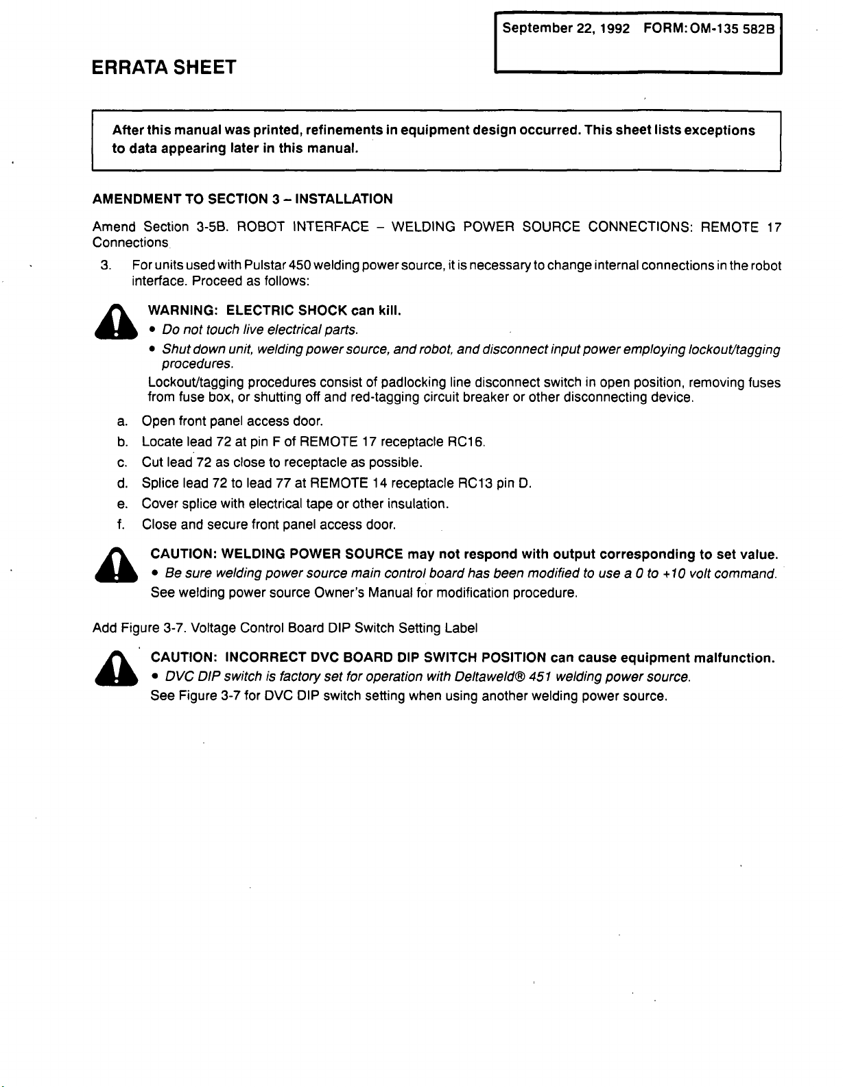
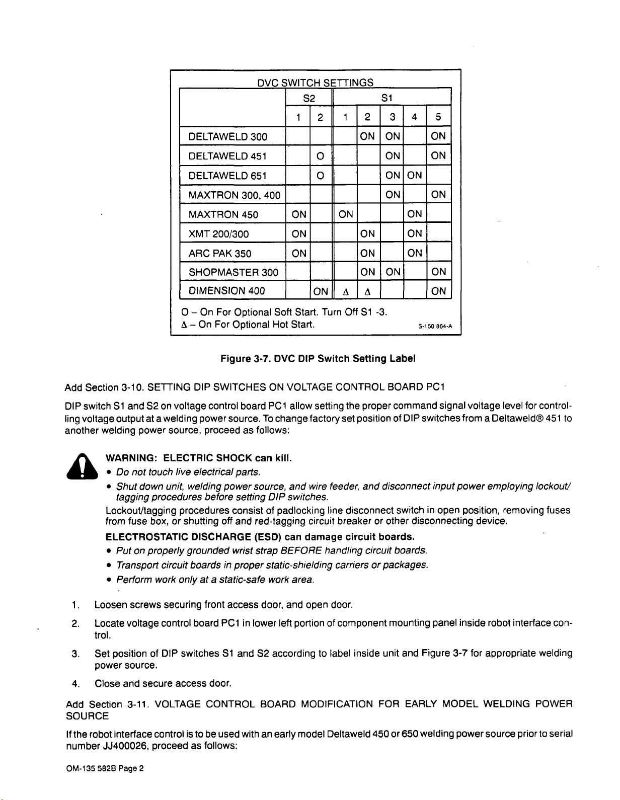
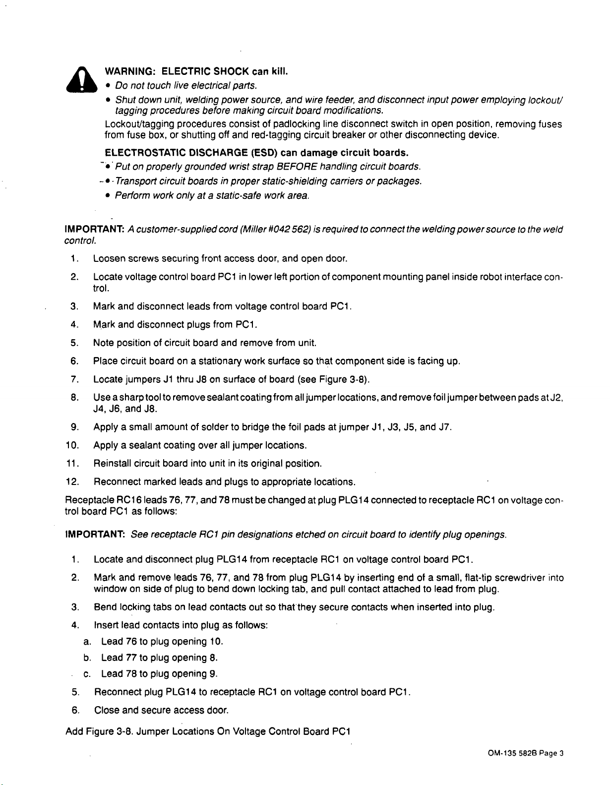
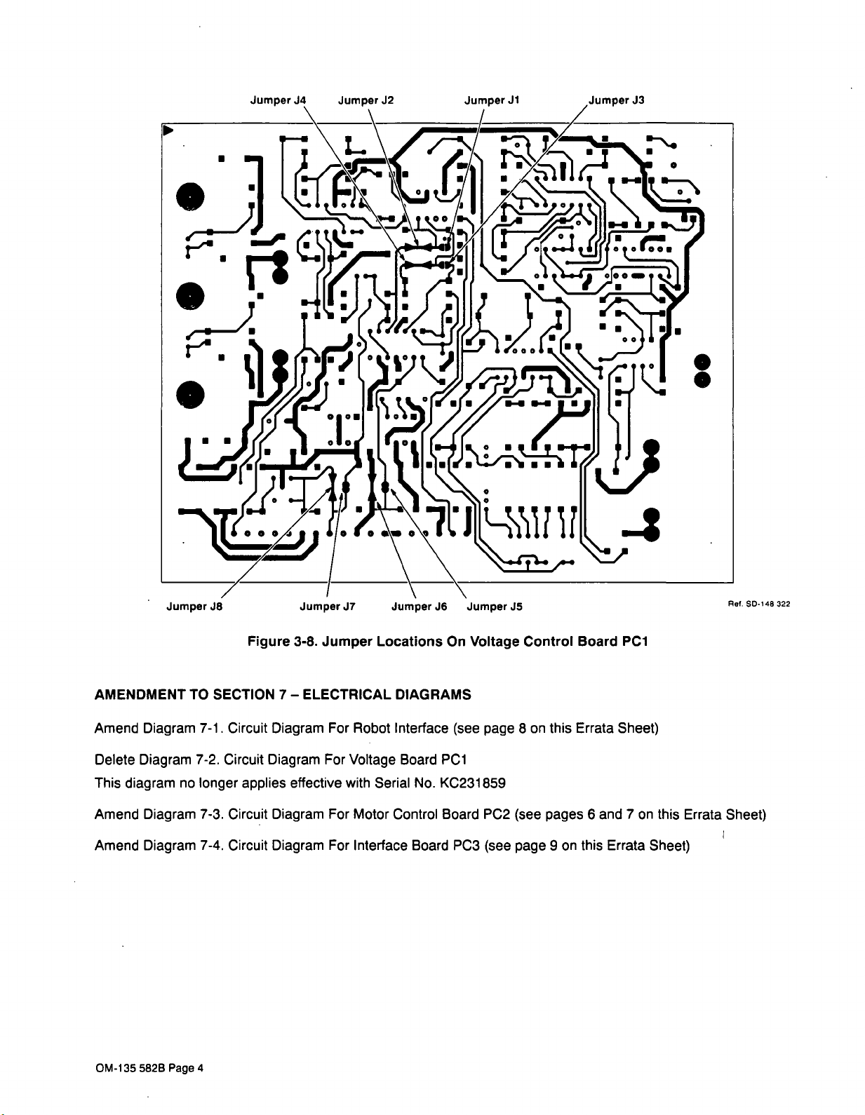
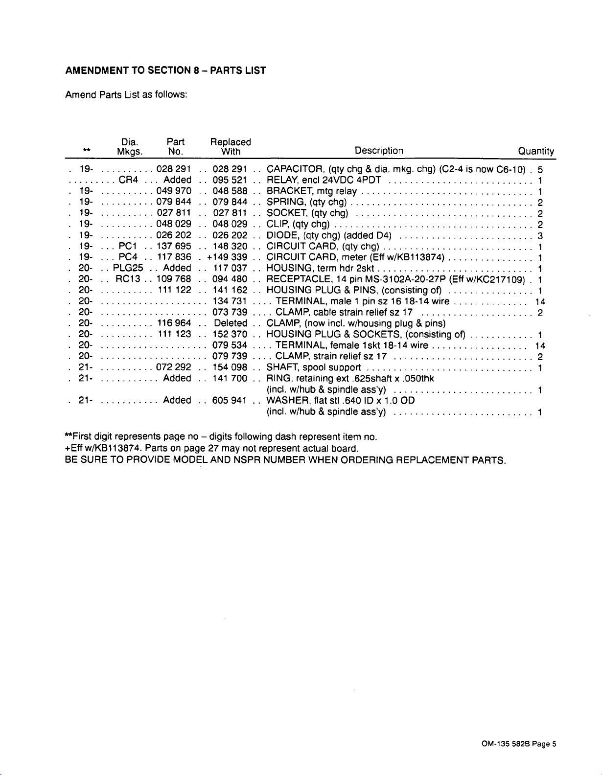
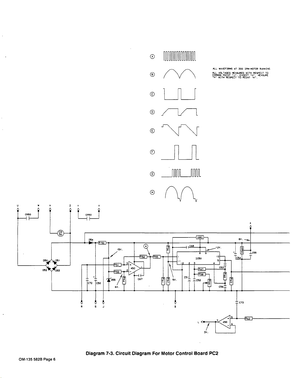
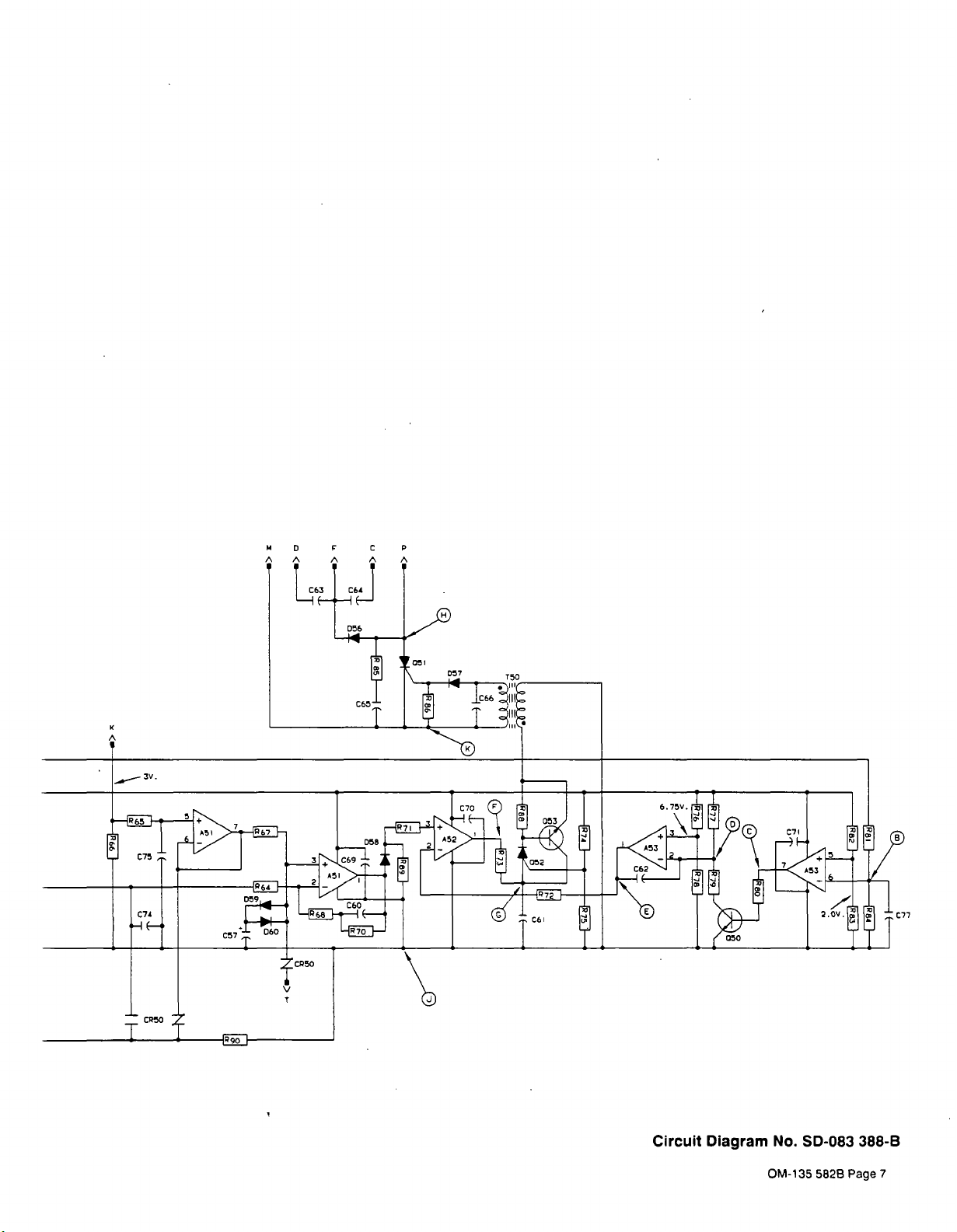
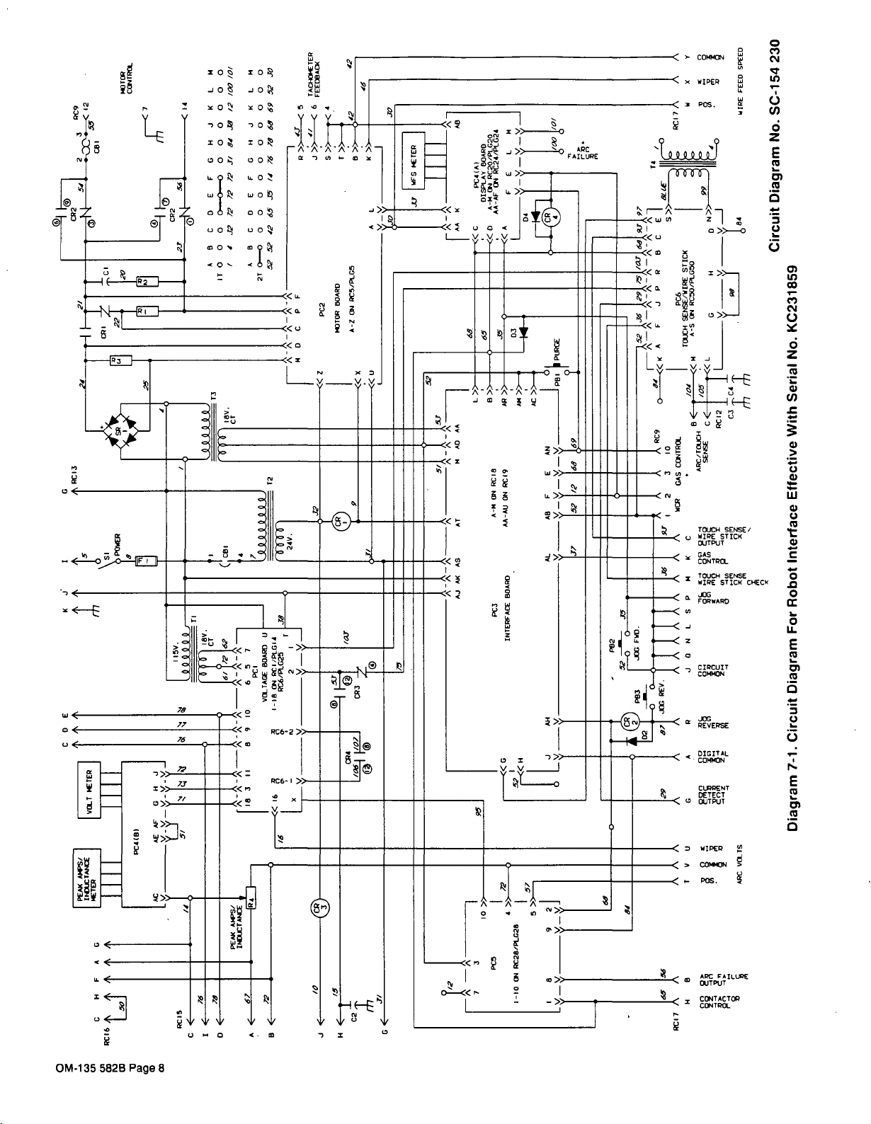
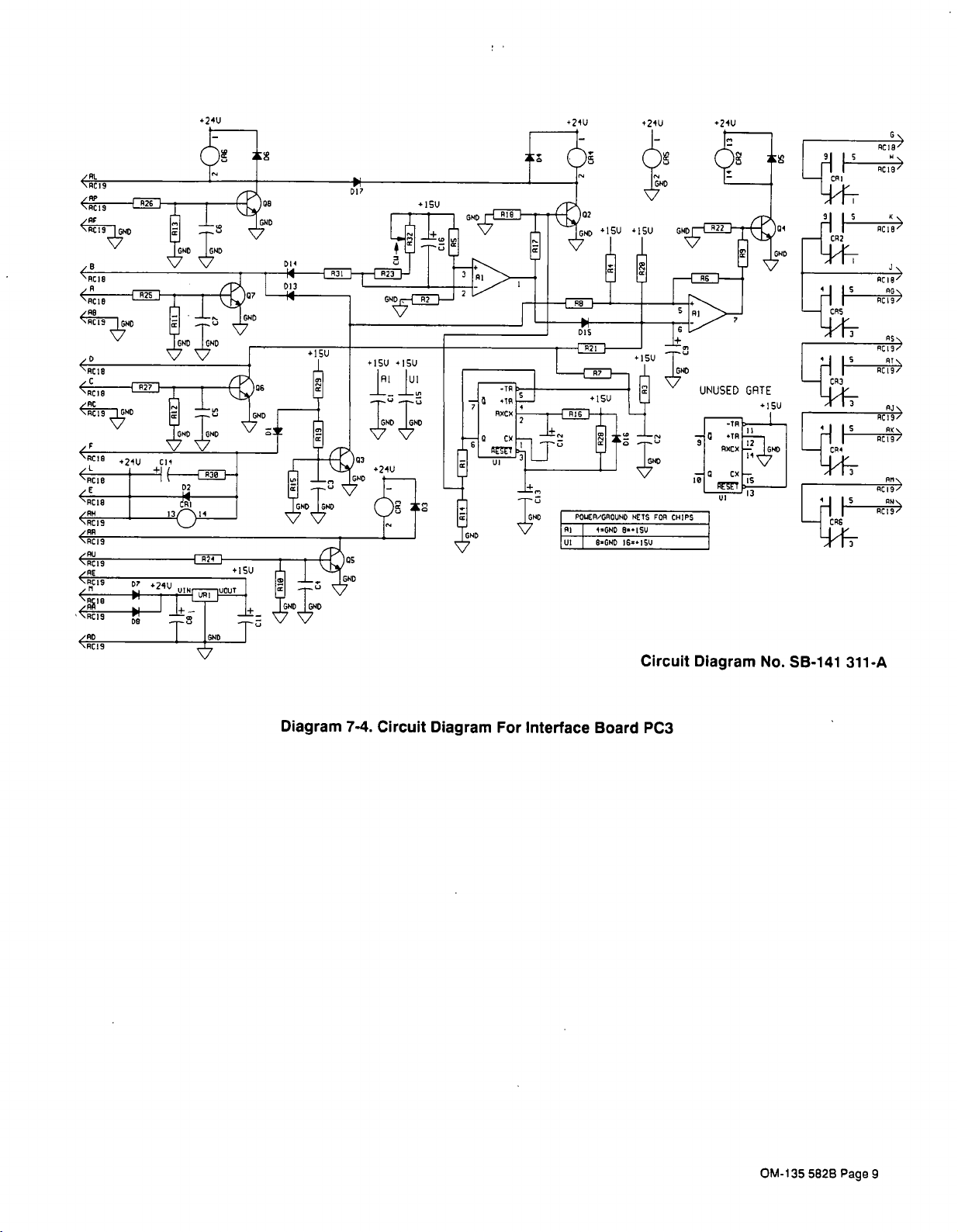

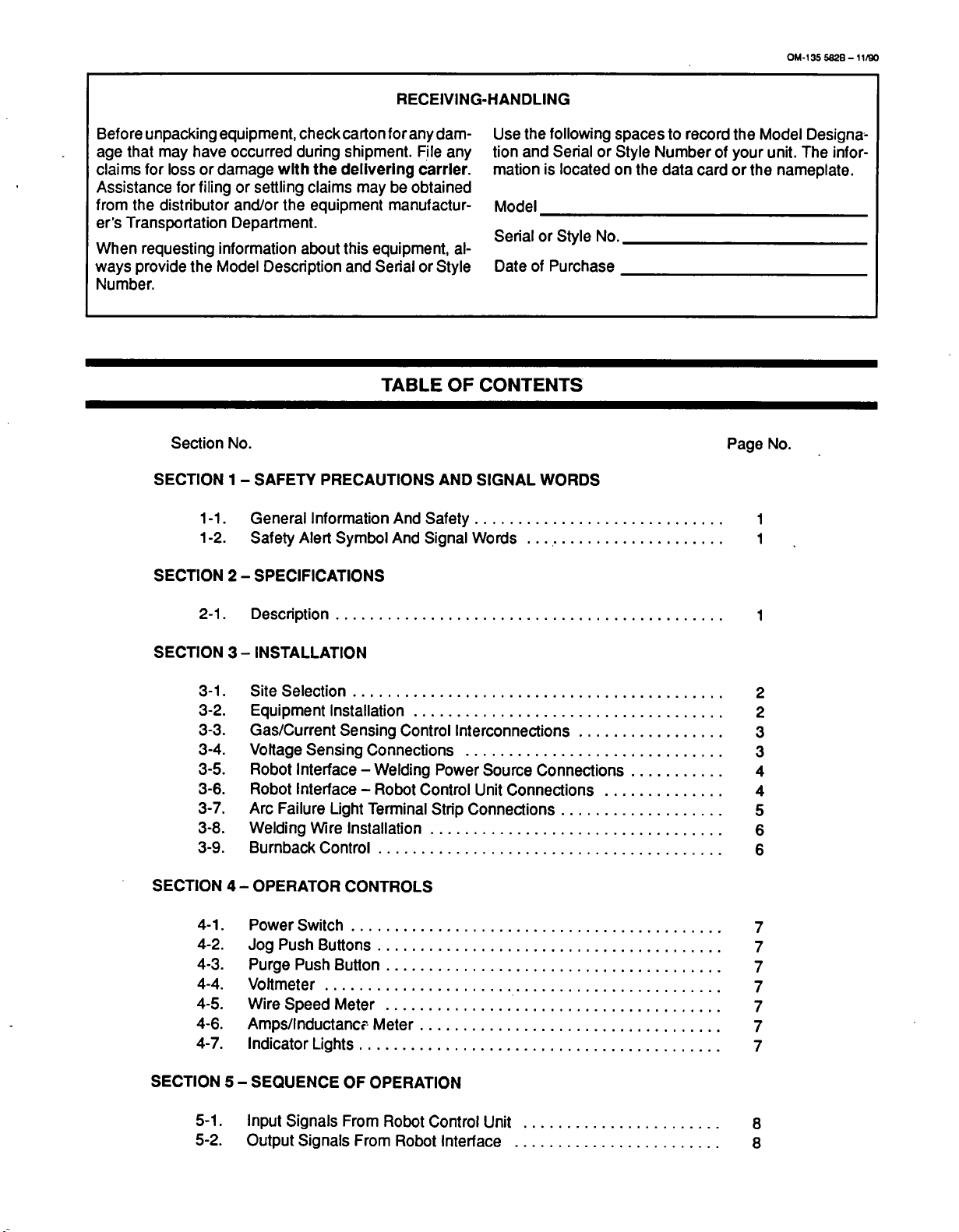
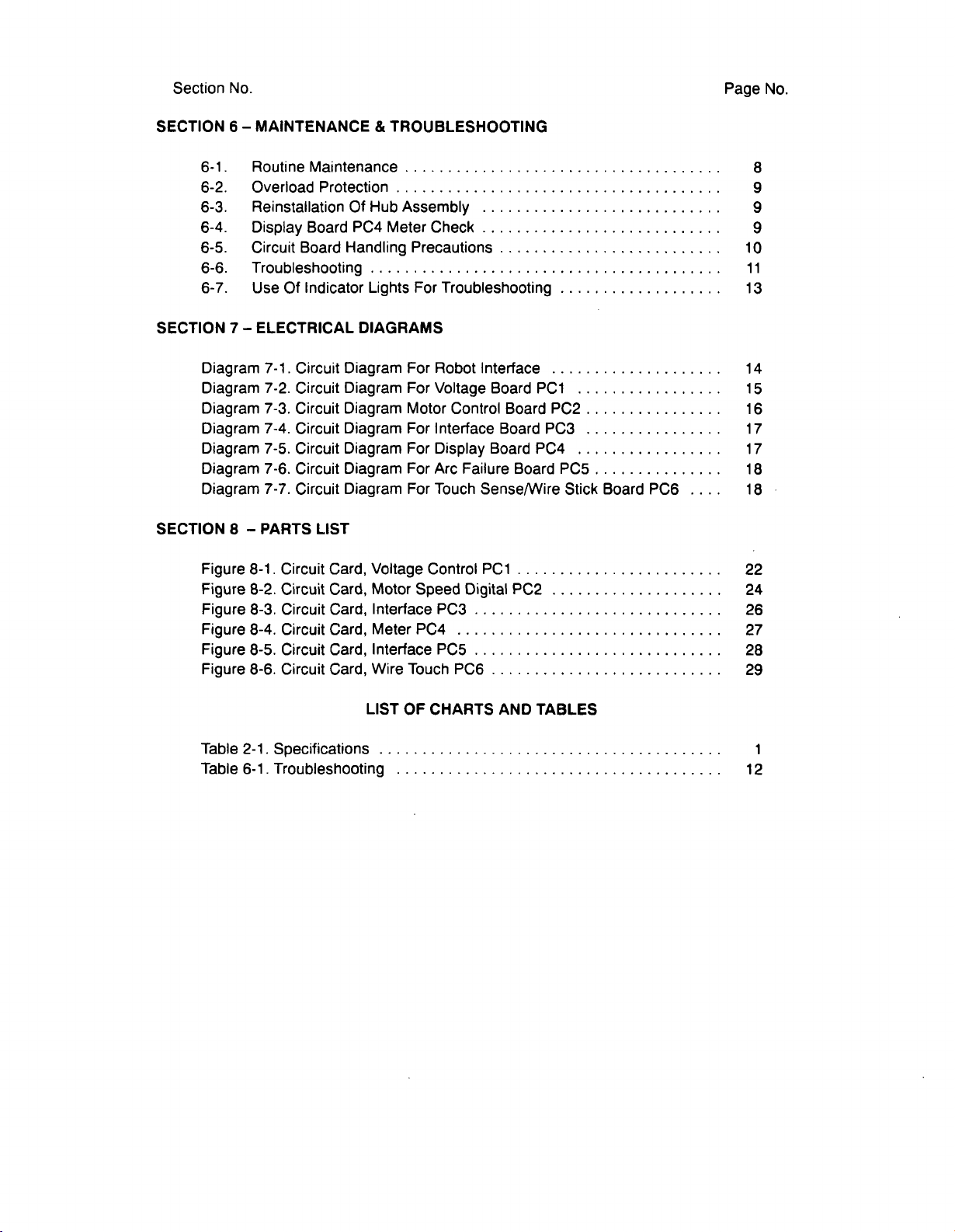


 Loading...