

Page 1
OM-294120A
Processes
Submerged Arc (SAW) Welding
Description
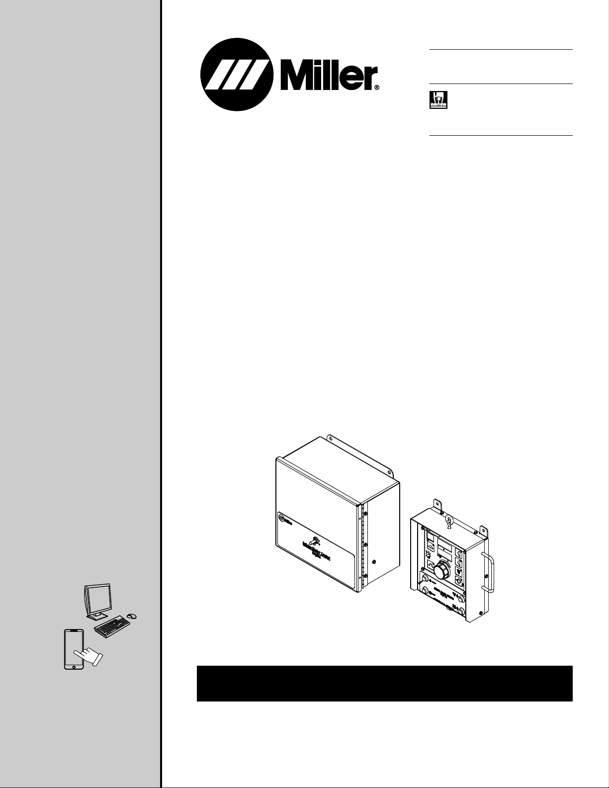
Submerged Arc Controller For Automatic
Welding
2023-05
SubArc Motor Control
And Remote Pendant
Digital CE
For product information,
Owner’s Manual translations,
and more, visit
www.MillerWelds.com
OWNER’S MANUAL
Page 2

From Miller to You
Thank you and congratulations on choosing Miller. Now you can get
the job done and get it done right. We know you don’t have time to do
it any other way.
That’s why when Niels Miller first started building arc welders in 1929,
he made sure his products offered long-lasting value and superior
quality. Like you, his customers couldn’t afford anything less. Miller
products had to be more than the best they could be. They had to be
the best you could buy.
Today, the people that build and sell Miller products continue the
tradition. They’re just as committed to providing equipment and
service that meets the high standards of quality and value established
in 1929.
This Owner’s Manual is designed to help you get the most out of your
Miller products. Please take time to read the Safety Precautions. They
will help you protect yourself against potential hazards on the
worksite. We’ve made installation and operation quick and easy. With
Miller, you can count on years of reliable service with proper
maintenance. And if for some reason the unit needs repair, there’s a
Troubleshooting section that will help you figure out what the problem
is, and our extensive service network is there to help fix the problem.
Working as hard as you do −
every power source from
Miller is backed by the most
hassle-free warranty in the
business.
Warranty and maintenance information for your particular model are
also provided.
Miller Electric manufactures a full line of
welders and welding-related equipment. For
information on other quality Miller products,
contact your local Miller distributor to receive
the latest full line catalog or individual
specification sheets. To locate your nearest
distributor or service agency call
1-800-4-A-Miller, or visit us at www.MillerWelds.com on the web.
Miller is the first welding
equipment manufacturer in the
U.S.A. to be registered to the
ISO 9001 Quality System
Standard.
Page 3

TABLE OF CONTENTS
SECTION 1 – SAFETY PRECAUTIONS – READ BEFORE USING. . . . . . . . . . . . . . . . . . . . . . . . . . . . . . . . . . . . . . . . . . . . . . . . . . . . . . . . . . . . . . . . . . 1
1-1 Symbol Usage . . . . . . . . . . . . . . . . . . . . . . . . . . . . . . . . . . . . . . . . . . . . . . . . . . . . . . . . . . . . . . . . . . . . . . . . . . . . . . . . . . . . . . . . . . . . . . . . . . . . . . 1
1-2 Arc Welding Hazards . . . . . . . . . . . . . . . . . . . . . . . . . . . . . . . . . . . . . . . . . . . . . . . . . . . . . . . . . . . . . . . . . . . . . . . . . . . . . . . . . . . . . . . . . . . . . . . . 1
1-3 Additional Hazards For Installation, Operation, And Maintenance . . . . . . . . . . . . . . . . . . . . . . . . . . . . . . . . . . . . . . . . . . . . . . . . . . . . . . . . . . 3
1-4 California Proposition 65 Warnings . . . . . . . . . . . . . . . . . . . . . . . . . . . . . . . . . . . . . . . . . . . . . . . . . . . . . . . . . . . . . . . . . . . . . . . . . . . . . . . . . . . . 4
1-5 Principal Safety Standards. . . . . . . . . . . . . . . . . . . . . . . . . . . . . . . . . . . . . . . . . . . . . . . . . . . . . . . . . . . . . . . . . . . . . . . . . . . . . . . . . . . . . . . . . . . . 4
1-6 EMF Information . . . . . . . . . . . . . . . . . . . . . . . . . . . . . . . . . . . . . . . . . . . . . . . . . . . . . . . . . . . . . . . . . . . . . . . . . . . . . . . . . . . . . . . . . . . . . . . . . . . . 4
SECTION 2 – CONSIGNES DE SÉCURITÉ - LIRE AVANT UTILISATION. . . . . . . . . . . . . . . . . . . . . . . . . . . . . . . . . . . . . . . . . . . . . . . . . . . . . . . . . . . . 5
2-1 Symboles utilisés. . . . . . . . . . . . . . . . . . . . . . . . . . . . . . . . . . . . . . . . . . . . . . . . . . . . . . . . . . . . . . . . . . . . . . . . . . . . . . . . . . . . . . . . . . . . . . . . . . . . 5
2-2 Dangers relatifs au soudage à l’arc . . . . . . . . . . . . . . . . . . . . . . . . . . . . . . . . . . . . . . . . . . . . . . . . . . . . . . . . . . . . . . . . . . . . . . . . . . . . . . . . . . . . 5
2-3 Symboles de dangers supplémentaires en relation avec l’installation, le fonctionnement et la maintenance . . . . . . . . . . . . . . . . . . . . . . 7
2-4 Proposition californienne 65 Avertissements . . . . . . . . . . . . . . . . . . . . . . . . . . . . . . . . . . . . . . . . . . . . . . . . . . . . . . . . . . . . . . . . . . . . . . . . . . . . 9
2-5 Principales normes de sécurité . . . . . . . . . . . . . . . . . . . . . . . . . . . . . . . . . . . . . . . . . . . . . . . . . . . . . . . . . . . . . . . . . . . . . . . . . . . . . . . . . . . . . . . . 9
2-6 Informations relatives aux CEM . . . . . . . . . . . . . . . . . . . . . . . . . . . . . . . . . . . . . . . . . . . . . . . . . . . . . . . . . . . . . . . . . . . . . . . . . . . . . . . . . . . . . . . 9
SECTION 3 – DEFINITIONS . . . . . . . . . . . . . . . . . . . . . . . . . . . . . . . . . . . . . . . . . . . . . . . . . . . . . . . . . . . . . . . . . . . . . . . . . . . . . . . . . . . . . . . . . . . . . . . . . . 10
3-1 Additional Safety Symbol Definitions . . . . . . . . . . . . . . . . . . . . . . . . . . . . . . . . . . . . . . . . . . . . . . . . . . . . . . . . . . . . . . . . . . . . . . . . . . . . . . . . . . 10
3-2 Miscellaneous Symbols And Definitions . . . . . . . . . . . . . . . . . . . . . . . . . . . . . . . . . . . . . . . . . . . . . . . . . . . . . . . . . . . . . . . . . . . . . . . . . . . . . . . 11
SECTION 4 – SPECIFICATIONS . . . . . . . . . . . . . . . . . . . . . . . . . . . . . . . . . . . . . . . . . . . . . . . . . . . . . . . . . . . . . . . . . . . . . . . . . . . . . . . . . . . . . . . . . . . . . . 12
4-1 Serial Number And Rating Label Location . . . . . . . . . . . . . . . . . . . . . . . . . . . . . . . . . . . . . . . . . . . . . . . . . . . . . . . . . . . . . . . . . . . . . . . . . . . . . 12
4-2 Software Licensing Agreement . . . . . . . . . . . . . . . . . . . . . . . . . . . . . . . . . . . . . . . . . . . . . . . . . . . . . . . . . . . . . . . . . . . . . . . . . . . . . . . . . . . . . . . 12
4-3 Information About Default Weld Parameters And Settings . . . . . . . . . . . . . . . . . . . . . . . . . . . . . . . . . . . . . . . . . . . . . . . . . . . . . . . . . . . . . . . . 12
4-4 Specifications. . . . . . . . . . . . . . . . . . . . . . . . . . . . . . . . . . . . . . . . . . . . . . . . . . . . . . . . . . . . . . . . . . . . . . . . . . . . . . . . . . . . . . . . . . . . . . . . . . . . . . 12
4-5 Environmental Specifications . . . . . . . . . . . . . . . . . . . . . . . . . . . . . . . . . . . . . . . . . . . . . . . . . . . . . . . . . . . . . . . . . . . . . . . . . . . . . . . . . . . . . . . . 13
4-6 SubArc System Compatibility . . . . . . . . . . . . . . . . . . . . . . . . . . . . . . . . . . . . . . . . . . . . . . . . . . . . . . . . . . . . . . . . . . . . . . . . . . . . . . . . . . . . . . . . 15
4-7 Power Source Compatibility With 14-Pin To SubArc Digital Converter . . . . . . . . . . . . . . . . . . . . . . . . . . . . . . . . . . . . . . . . . . . . . . . . . . . . . . 16
SECTION 5 – INSTALLATION. . . . . . . . . . . . . . . . . . . . . . . . . . . . . . . . . . . . . . . . . . . . . . . . . . . . . . . . . . . . . . . . . . . . . . . . . . . . . . . . . . . . . . . . . . . . . . . . . 17
5-1 Dimensions And Mounting Hole Layout . . . . . . . . . . . . . . . . . . . . . . . . . . . . . . . . . . . . . . . . . . . . . . . . . . . . . . . . . . . . . . . . . . . . . . . . . . . . . 17
SECTION 6 – SYSTEM CONNECTIONS . . . . . . . . . . . . . . . . . . . . . . . . . . . . . . . . . . . . . . . . . . . . . . . . . . . . . . . . . . . . . . . . . . . . . . . . . . . . . . . . . . . . . . . 18
6-1 Left Side Panel Connections For SubArc Motor Control Digital . . . . . . . . . . . . . . . . . . . . . . . . . . . . . . . . . . . . . . . . . . . . . . . . . . . . . . . . . . . . 18
6-2 Bottom Panel Connections For SubArc Remote Pendant Digital . . . . . . . . . . . . . . . . . . . . . . . . . . . . . . . . . . . . . . . . . . . . . . . . . . . . . . . . . . 19
6-3 Remote Receptacle RC1 Information For SubArc Motor Control Digital . . . . . . . . . . . . . . . . . . . . . . . . . . . . . . . . . . . . . . . . . . . . . . . . . . . . 19
6-4 Remote Receptacle RC2 Information For SubArc Motor Control Digital . . . . . . . . . . . . . . . . . . . . . . . . . . . . . . . . . . . . . . . . . . . . . . . . . . . . 19
6-5 Remote Receptacle RC3 Information For SubArc Motor Control Digital . . . . . . . . . . . . . . . . . . . . . . . . . . . . . . . . . . . . . . . . . . . . . . . . . . . . 19
6-6 Remote Receptacle RC4 Information For SubArc Remote Pendant Digital And Motor Control Digital . . . . . . . . . . . . . . . . . . . . . . . . . . . 20
6-7 Terminal Block TB1 And TB2 Connections For SubArc Motor Control Digital . . . . . . . . . . . . . . . . . . . . . . . . . . . . . . . . . . . . . . . . . . . . . . . . 21
6-8 Terminal Block TB1 Connections For SubArc Motor Control Digital . . . . . . . . . . . . . . . . . . . . . . . . . . . . . . . . . . . . . . . . . . . . . . . . . . . . . . . . 22
6-9 Terminal Block TB2 Connections For SubArc Motor Control Digital . . . . . . . . . . . . . . . . . . . . . . . . . . . . . . . . . . . . . . . . . . . . . . . . . . . . . . . . 22
6-10 SubArc Motor Control Digital Plug Connections . . . . . . . . . . . . . . . . . . . . . . . . . . . . . . . . . . . . . . . . . . . . . . . . . . . . . . . . . . . . . . . . . . . . . . . . . 23
SECTION 7 – OPERATION . . . . . . . . . . . . . . . . . . . . . . . . . . . . . . . . . . . . . . . . . . . . . . . . . . . . . . . . . . . . . . . . . . . . . . . . . . . . . . . . . . . . . . . . . . . . . . . . . . . 24
7-1 Weld Control Definitions . . . . . . . . . . . . . . . . . . . . . . . . . . . . . . . . . . . . . . . . . . . . . . . . . . . . . . . . . . . . . . . . . . . . . . . . . . . . . . . . . . . . . . . . . . . . . 24
7-2 Weld Sequence Displays . . . . . . . . . . . . . . . . . . . . . . . . . . . . . . . . . . . . . . . . . . . . . . . . . . . . . . . . . . . . . . . . . . . . . . . . . . . . . . . . . . . . . . . . . . . . 26
7-3 Weld Sequence Parameters In A Program . . . . . . . . . . . . . . . . . . . . . . . . . . . . . . . . . . . . . . . . . . . . . . . . . . . . . . . . . . . . . . . . . . . . . . . . . . . . . 27
7-4 Setup Screens . . . . . . . . . . . . . . . . . . . . . . . . . . . . . . . . . . . . . . . . . . . . . . . . . . . . . . . . . . . . . . . . . . . . . . . . . . . . . . . . . . . . . . . . . . . . . . . . . . . . . 28
7-5 Setup Screens (Continued) . . . . . . . . . . . . . . . . . . . . . . . . . . . . . . . . . . . . . . . . . . . . . . . . . . . . . . . . . . . . . . . . . . . . . . . . . . . . . . . . . . . . . . . . . . 29
7-6 Setup Screens (Continued) . . . . . . . . . . . . . . . . . . . . . . . . . . . . . . . . . . . . . . . . . . . . . . . . . . . . . . . . . . . . . . . . . . . . . . . . . . . . . . . . . . . . . . . . . . 30
7-7 Auxiliary Menus Screens . . . . . . . . . . . . . . . . . . . . . . . . . . . . . . . . . . . . . . . . . . . . . . . . . . . . . . . . . . . . . . . . . . . . . . . . . . . . . . . . . . . . . . . . . . . . 31
7-8 Auxiliary Menus Screens (Continued) . . . . . . . . . . . . . . . . . . . . . . . . . . . . . . . . . . . . . . . . . . . . . . . . . . . . . . . . . . . . . . . . . . . . . . . . . . . . . . . . . 32
7-9 Auxiliary Menus Screens (Continued) . . . . . . . . . . . . . . . . . . . . . . . . . . . . . . . . . . . . . . . . . . . . . . . . . . . . . . . . . . . . . . . . . . . . . . . . . . . . . . . . . 33
7-10 Auxiliary Menus Screens (Continued) . . . . . . . . . . . . . . . . . . . . . . . . . . . . . . . . . . . . . . . . . . . . . . . . . . . . . . . . . . . . . . . . . . . . . . . . . . . . . . . . . 34
7-11 Auxiliary Menus Screens (Continued) . . . . . . . . . . . . . . . . . . . . . . . . . . . . . . . . . . . . . . . . . . . . . . . . . . . . . . . . . . . . . . . . . . . . . . . . . . . . . . . . . 35
7-12 Auxiliary Menus Screens (Continued) . . . . . . . . . . . . . . . . . . . . . . . . . . . . . . . . . . . . . . . . . . . . . . . . . . . . . . . . . . . . . . . . . . . . . . . . . . . . . . . . . 36
7-13 Remote Program Select For SubArc Motor Control Digital. . . . . . . . . . . . . . . . . . . . . . . . . . . . . . . . . . . . . . . . . . . . . . . . . . . . . . . . . . . . . . . . 37
SECTION 8 – MAINTENANCE AND TROUBLESHOOTING . . . . . . . . . . . . . . . . . . . . . . . . . . . . . . . . . . . . . . . . . . . . . . . . . . . . . . . . . . . . . . . . . . . . . . 38
8-1 Routine Maintenance . . . . . . . . . . . . . . . . . . . . . . . . . . . . . . . . . . . . . . . . . . . . . . . . . . . . . . . . . . . . . . . . . . . . . . . . . . . . . . . . . . . . . . . . . . . . . . . 38
8-2 Troubleshooting Table . . . . . . . . . . . . . . . . . . . . . . . . . . . . . . . . . . . . . . . . . . . . . . . . . . . . . . . . . . . . . . . . . . . . . . . . . . . . . . . . . . . . . . . . . . . . . . 39
8-3 Help Codes. . . . . . . . . . . . . . . . . . . . . . . . . . . . . . . . . . . . . . . . . . . . . . . . . . . . . . . . . . . . . . . . . . . . . . . . . . . . . . . . . . . . . . . . . . . . . . . . . . . . . . . . 40
SECTION 9 – ELECTRICAL DIAGRAMS . . . . . . . . . . . . . . . . . . . . . . . . . . . . . . . . . . . . . . . . . . . . . . . . . . . . . . . . . . . . . . . . . . . . . . . . . . . . . . . . . . . . . . . 42
Page 4
DECLARATION OF CONFORMITY
for European Community (CE marked) products.
MILLER Electric Mfg. LLC, 1635 Spencer Street, Appleton, WI 54914 U.S.A. declares that the
product(s) identified in this declaration conform to the essential requirements and provisions of
the stated Council Directive(s), Commission Regulation(s) and Standard(s).
Product/Apparatus Identification:
Product Stock Number
SUBARC WIRE DRIVE 400 DIGITAL LOW VOLTAGE 300938
SUBARC INTERFACE DIGITAL 300936
SUBARC MOTOR CONTROL DIGITAL 301425
SUBARC REMOTE PENDANT DIGITAL 301424
SUBARC TRACTOR INTERFACE DIGITAL 301423
SUBARC WIRE DRIVE 200 DIGITAL LOW VOLTAGE 301596
Council Directives and Commission Regulations:
• 2014/35/EU Low voltage
• 2014/30/EU Electromagnetic compatibility
• 2011/65/EU and amendment 2015/863 Restriction of the use of certain hazardous substances in electrical
and electronic equipment
Standards:
• EN IEC 60974−5:2019 Arc welding equipment – Part 5: Wire feeders
• EN 60974−10:2014/A1:2015 Arc welding equipment – Part 10: Electromagnetic compatibility requirements
• EN IEC 63000:2018 – Technical documentation for the assessment of electrical and electronic products
with respect to the restriction of hazardous substances
Signatory:
February 23, 2022
_____________________________________
David A. Werba
MANAGER, PRODUCT DESIGN COMPLIANCE
___________________________________________
Date of Declaration
268181F
Page 5
DECLARATION OF CONFORMITY
For United Kingdom (UKCA marked) products.
MILLER Electric Mfg. LLC, 1635 West Spencer Street, Appleton, WI 54914 U.S.A. declares that
the product(s) identified in this declaration conform to the essential requirements and
provisions of the stated Regulation(s) and Standard(s).
Product/Apparatus Identification:
Product Stock Number
SUBARC WIRE DRIVE 400 DIGITAL LOW VOLTAGE 300938
SUBARC INTERFACE DIGITAL 300936
SUBARC MOTOR CONTROL DIGITAL 301425
SUBARC REMOTE PENDANT DIGITAL 301424
SUBARC TRACTOR INTERFACE DIGITAL 301423
SUBARC WIRE DRIVE 200 DIGITAL LOW VOLTAGE 301596
Regulations:
· S.I. 2016/1101 Electrical Equipment (Safety) Regulations 2016
· S.I. 2016/1091 Electromagnetic Compatibility Regulations 2016
· S.I. 2012/3032 Restriction of the Use of Certain Hazardous Substances in Electrical and
Electronic Equipment Regulations 2012
Standards:
· EN IEC 60974−5:2019 Arc welding equipment – Part 5: Wire feeders
· EN 60974−10:2014/A1:2015 Arc welding equipment – Part 10: Electromagnetic compatibility
requirements
· EN IEC 63000:2018 Technical documentation for the assessment of electrical and electronic
products with respect to the restriction of hazardous substances
Signatory:
February 23, 2022
_____________________________________ ___________________________________________
David A. Werba
MANAGER, PRODUCT DESIGN COMPLIANCE
Date of Declaration
290536B
Page 6
SECTION 1 – SAFETY PRECAUTIONS – READ BEFORE USING
Protect yourself and others from injury—read, follow, and save these important safety precautions and operating instructions.
1-1. Symbol Usage
DANGER! – Indicates a hazardous situation which, if not
avoided, will result in death or serious injury. The possible
hazards are shown in the adjoining symbols or explained
in the text.
Indicates a hazardous situation which, if not avoided,
could result in death or serious injury. The possible hazards are shown in the adjoining symbols or explained in
the text.
NOTICE – Indicates statements not related to personal injury.
Indicates special instructions.
F
1-2. Arc Welding Hazards
The symbols shown below are used throughout this manual
to call attention to and identify possible hazards. When you
see the symbol, watch out, and follow the related instructions to avoid the hazard. The safety information given below is only a summary of the more complete safety
information found in the Principal Safety Standards. Read
and follow all Safety Standards.
Only qualified persons should install, operate, maintain,
and repair this equipment. A qualified person is defined as
one who, by possession of a recognized degree, certificate,
or professional standing, or who by extensive knowledge,
training and experience, has successfully demonstrated the
ability to solve or resolve problems relating to the subject
matter, the work, or the project and has received safety
training to recognize and avoid the hazards involved.
During operation, keep everybody, especially children,
away.
ELECTRIC SHOCK can kill.
Touching live electrical parts can cause fatal
shocks or severe burns. The electrode and work
circuit is electrically live whenever the output is on.
cuits are also live when power is on. In semiautomatic or automatic
wire welding, the wire, wire reel, drive roll housing, and all metal parts
touching the welding wire are electrically live. Incorrectly installed or
improperly grounded equipment is a hazard.
l Do not touch live electrical parts.
l Wear dry, hole-free insulating gloves and body protection.
l Insulate yourself from work and ground using dry insulating mats
or covers big enough to prevent any physical contact with the work
or ground.
l Do not use AC weld output in damp, wet, or confined spaces, or if
there is a danger of falling.
l Use AC output ONLY if required for the welding process.
l If AC output is required, use remote output control if present on
unit.
l Additional safety precautions are required when any of the follow-
ing electrically hazardous conditions are present: in damp locations or while wearing wet clothing; on metal structures such as
floors, gratings, or scaffolds; when in cramped positions such as
sitting, kneeling, or lying; or when there is a high risk of unavoidable or accidental contact with the workpiece or ground. For these
conditions, use the following equipment in order presented: 1) a
semiautomatic DC constant voltage (wire) welder, 2) a DC manual
The input power circuit and machine internal cir-
This group of symbols means Warning! Watch Out! ELECTRIC
SHOCK, MOVING PARTS, and HOT PARTS hazards. Consult
symbols and related instructions below for necessary actions to
avoid these hazards.
(stick) welder, or 3) an AC welder with reduced open-circuit voltage. In most situations, use of a DC, constant voltage wire welder
is recommended. And, do not work alone!
l Disconnect input power or stop engine before installing or servic-
ing this equipment. Lockout/tagout input power according to
OSHA 29 CFR 1910.147 (see Safety Standards).
l Properly install, ground, and operate this equipment according to
its Owner’s Manual and national, state, and local codes.
l Always verify the supply ground —check and be sure that input
power cord ground wire is properly connected to ground terminal
in disconnect box or that cord plug is connected to a properly
grounded receptacle outlet.
l When making input connections, attach proper grounding conduc-
tor first—double-check connections.
l Keep cords dry, free of oil and grease, and protected from hot met-
al and sparks.
l Frequently inspect input power cord and ground conductor for
damage or bare wiring —replace immediately if damaged —bare
wiring can kill.
l Turn off all equipment when not in use.
l Do not use worn, damaged, undersized, or repaired cables.
l Do not drape cables over your body.
l If earth grounding of the workpiece is required, ground it directly
with a separate cable.
l Do not touch electrode if you are in contact with the work, ground,
or another electrode from a different machine.
l Use only well-maintained equipment. Repair or replace damaged
parts at once. Maintain unit according to manual.
l Do not touch electrode holders connected to two welding ma-
chines at the same time since double open-circuit voltage will be
present.
l Wear a safety harness if working above floor level.
l Keep all panels and covers securely in place.
l Clamp work cable with good metal-to-metal contact to workpiece
or worktable as near the weld as practical.
l Insulate work clamp when not connected to workpiece to prevent
contact with any metal object.
l Do not connect more than one electrode or work cable to any sin-
gle weld output terminal. Disconnect cable for process not in use.
l Use GFCI protection when operating auxiliary equipment in damp
or wet locations.
OM-294120 Page 1
Page 7
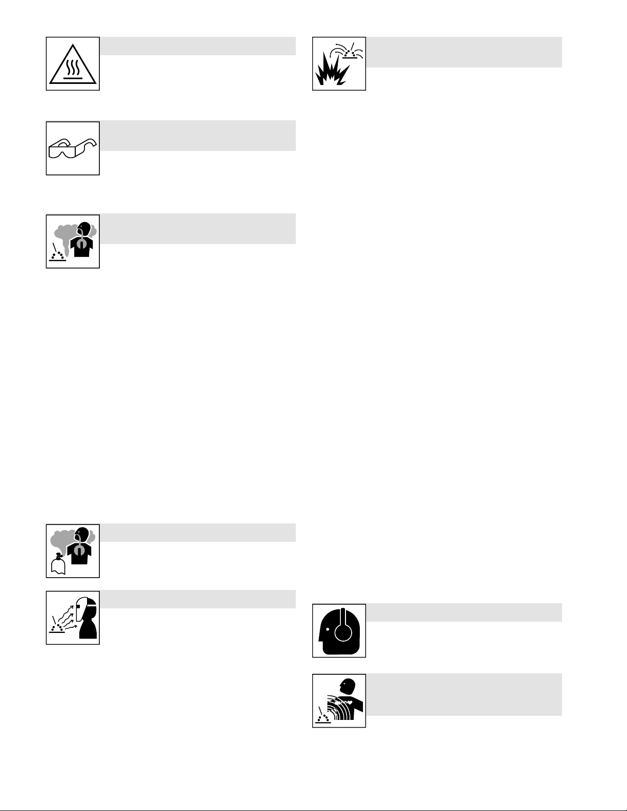
HOT PARTS can burn.
l Do not touch hot parts bare handed.
l Allow cooling period before working on equipment.
l To handle hot parts, use proper tools and/or wear
heavy, insulated welding gloves and clothing to
prevent burns.
FLYING METAL OR DIRT can injure
eyes.
l Welding, chipping, wire brushing, and grinding
cause sparks and flying metal. As welds cool, they
can throw off slag.
l Wear approved safety glasses with side shields even under your
welding helmet.
FUMES AND GASES can be
hazardous.
Welding produces fumes and gases. Breathing
these fumes and gases can be hazardous to your
health.
l Keep your head out of the fumes. Do not breathe the fumes.
l Ventilate the work area and/or use local forced ventilation at the
arc to remove welding fumes and gases. The recommended way
to determine adequate ventilation is to sample for the composition
and quantity of fumes and gases to which personnel are exposed.
l If ventilation is poor, wear an approved air-supplied respirator.
l Read and understand the Safety Data Sheets (SDSs) and the
manufacturer’s instructions for adhesives, coatings, cleaners, consumables, coolants, degreasers, fluxes, and metals.
l Work in a confined space only if it is well ventilated, or while wear-
ing an air-supplied respirator. Always have a trained watchperson
nearby. Welding fumes and gases can displace air and lower the
oxygen level causing injury or death. Be sure the breathing air is
safe.
l Do not weld in locations near degreasing, cleaning, or spraying
operations. The heat and rays of the arc can react with vapors to
form highly toxic and irritating gases.
l Do not weld on coated metals, such as galvanized, lead, or cadmi-
um plated steel, unless the coating is removed from the weld area,
the area is well ventilated, and while wearing an air-supplied respirator. The coatings and any metals containing these elements can
give off toxic fumes if welded.
BUILDUP OF GAS can injure or kill.
l Shut off compressed gas supply when not in use.
l Always ventilate confined spaces or use approved
air-supplied respirator.
ARC RAYS can burn eyes and skin.
Arc rays from the welding process produce intense
visible and invisible (ultraviolet and infrared) rays
that can burn eyes and skin. Sparks fly off from the
weld.
l Wear an approved welding helmet fitted with a proper shade of fil-
ter lenses to protect your face and eyes from arc rays and sparks
when welding or watching (see ANSI Z49.1 and Z87.1 listed in
Safety Standards).
l Wear approved safety glasses with side shields under your
helmet.
l Use protective screens or barriers to protect others from flash,
glare, and sparks; warn others not to watch the arc.
l Wear body protection made from leather or flame-resistant cloth-
ing (FRC). Body protection includes oil-free clothing such as leather gloves, heavy shirt, cuffless trousers, high shoes, and a cap.
WELDING can cause fire or
explosion.
Welding on closed containers, such as tanks,
drums, or pipes, can cause them to blow up.
Sparks can fly off from the welding arc. The flying
sparks, hot workpiece, and hot equipment can cause fires and burns.
Accidental contact of electrode to metal objects can cause sparks, explosion, overheating, or fire. Check and be sure the area is safe before doing any welding.
l Remove all flammables within 35 ft (10.7 m) of the welding arc. If
this is not possible, tightly cover them with approved covers.
l Do not weld where flying sparks can strike flammable material.
l Protect yourself and others from flying sparks and hot metal.
l Be alert that welding sparks and hot materials from welding can
easily go through small cracks and openings to adjacent areas.
l Watch for fire, and keep a fire extinguisher nearby.
l Be aware that welding on a ceiling, floor, bulkhead, or partition can
cause fire on the hidden side.
l Do not cut or weld on tire rims or wheels. Tires can explode if
heated. Repaired rims and wheels can fail. See OSHA 29 CFR
1910.177 listed in Safety Standards.
l Do not weld on containers that have held combustibles, or on
closed containers such as tanks, drums, or pipes unless they are
properly prepared according to AWS F4.1 (see Safety Standards).
l Do not weld where the atmosphere can contain flammable dust,
gas, or liquid vapors (such as gasoline).
l Connect work cable to the work as close to the welding area as
practical to prevent welding current from traveling long, possibly
unknown paths and causing electric shock, sparks, and fire
hazards.
l Do not use welder to thaw frozen pipes.
l Remove stick electrode from holder or cut off welding wire at con-
tact tip when not in use.
l Wear body protection made from leather or flame-resistant cloth-
ing (FRC). Body protection includes oil-free clothing such as leather gloves, heavy shirt, cuffless trousers, high shoes, and a cap.
l Remove any combustibles, such as a butane lighter or matches,
from your person before doing any welding.
l After completion of work, inspect area to ensure it is free of sparks,
glowing embers, and flames.
l Use only correct fuses or circuit breakers. Do not oversize or by-
pass them.
l Follow requirements in OSHA 1910.252 (a) (2) (iv) and NFPA 51B
for hot work and have a fire watcher and extinguisher nearby.
l Read and understand the Safety Data Sheets (SDSs) and the
manufacturer’s instructions for adhesives, coatings, cleaners, consumables, coolants, degreasers, fluxes, and metals.
NOISE can damage hearing.
Noise from some processes or equipment can
damage hearing.
l Wear approved ear protection if noise level is high.
ELECTRIC AND MAGNETIC FIELDS
(EMF) can affect Implanted Medical
Devices.
l Wearers of Pacemakers and other Implanted Med-
ical Devices should keep away.
l Implanted Medical Device wearers should consult their doctor and
the device manufacturer before going near arc welding, spot welding, gouging, plasma arc cutting, or induction heating operations.
OM-294120 Page 2
Page 8
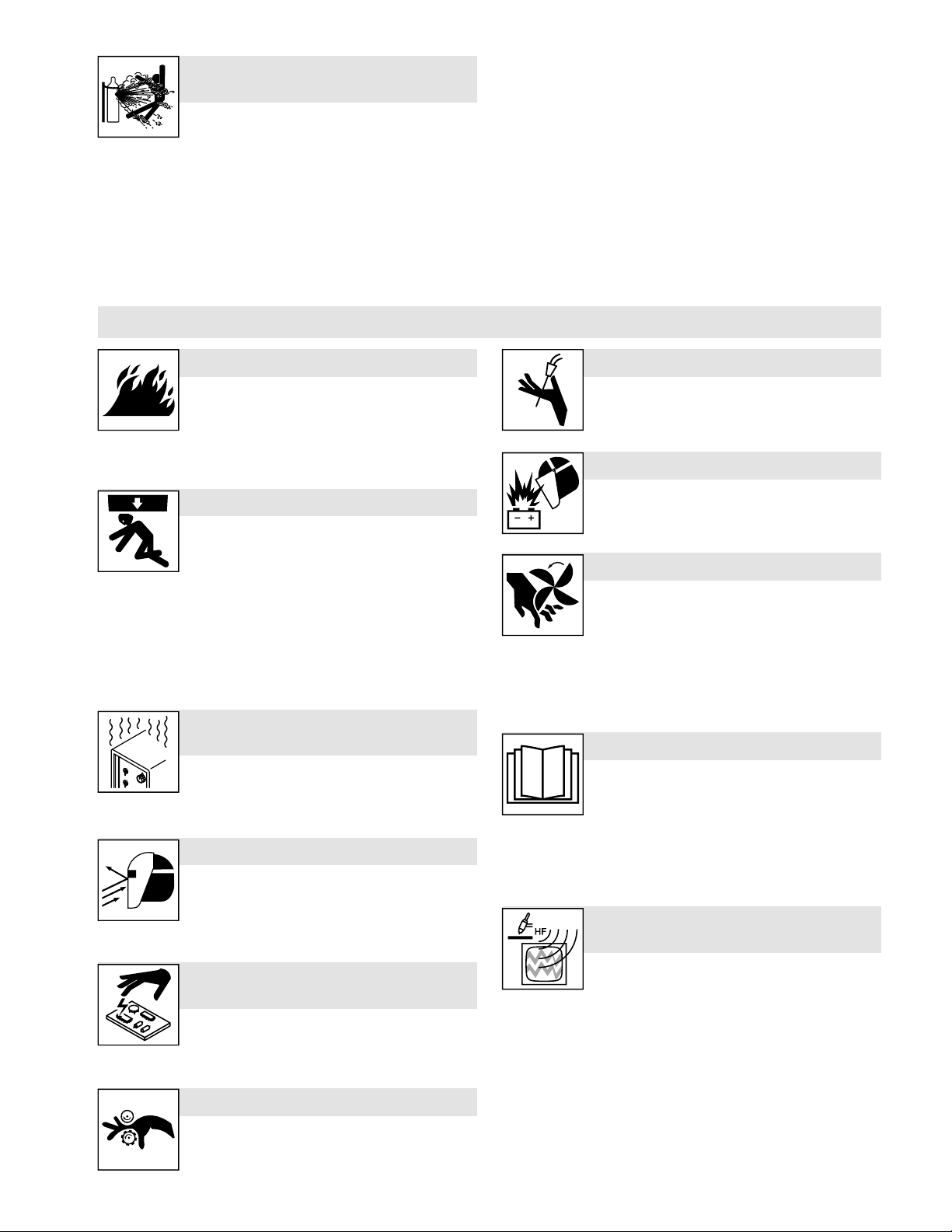
CYLINDERS can explode if
damaged.
Compressed gas cylinders contain gas under high
pressure. If damaged, a cylinder can explode.
Since gas cylinders are normally part of the weld-
ing process, be sure to treat them carefully.
l Protect compressed gas cylinders from excessive heat, mechani-
cal shocks, physical damage, slag, open flames, sparks, and arcs.
l Install cylinders in an upright position by securing to a stationary
support or cylinder rack to prevent falling or tipping.
l Keep cylinders away from any welding or other electrical circuits.
l Never drape a welding torch over a gas cylinder.
l Never allow a welding electrode to touch any cylinder.
l Never weld on a pressurized cylinder—explosion will result.
l Use only correct compressed gas cylinders, regulators, hoses,
and fittings designed for the specific application; maintain them
and associated parts in good condition.
l Turn face away from valve outlet when opening cylinder valve. Do
not stand in front of or behind the regulator when opening the
valve.
l Keep protective cap in place over valve except when cylinder is in
use or connected for use.
l Use the proper equipment, correct procedures, and sufficient
number of persons to lift, move, and transport cylinders.
l Read and follow instructions on compressed gas cylinders, asso-
ciated equipment, and Compressed Gas Association (CGA) publication P-1 listed in Safety Standards.
1-3. Additional Hazards For Installation, Operation, And Maintenance
FIRE OR EXPLOSION hazard.
l Do not install or place unit on, over, or near com-
bustible surfaces.
l Do not install unit near flammables.
l Do not overload building wiring — be sure power
supply system is properly sized, rated, and protected to handle
this unit.
FALLING EQUIPMENT can injure.
l Use lifting eye to lift unit only, NOT running gear,
gas cylinders, or any other accessories.
l Use correct procedures and equipment of ad-
equate capacity to lift and support unit.
l If using lift forks to move unit, be sure forks are long enough to ex-
tend beyond opposite side of unit.
l Keep equipment (cables and cords) away from moving vehicles
when working from an aerial location.
l Follow the guidelines in the Applications Manual for the Revised
NIOSH Lifting Equation (Publication No. 94-110) when manually
lifting heavy parts or equipment.
OVERUSE can cause
OVERHEATING.
l Allow cooling period; follow rated duty cycle.
l Reduce current or reduce duty cycle before start-
ing to weld again.
l Do not block or filter airflow to unit.
FLYING SPARKS can injure.
l Wear a face shield to protect eyes and face.
l Shape tungsten electrode only on grinder with
proper guards in a safe location wearing proper
face, hand, and body protection.
l Sparks can cause fires—keep flammables away.
STATIC (ESD) can damage PC
boards.
l Put on grounded wrist strap BEFORE handling
boards or parts.
l Use proper static-proof bags and boxes to store,
move, or ship PC boards.
MOVING PARTS can injure.
l Keep away from moving parts.
l Keep away from pinch points such as drive rolls.
OM-294120 Page 3
WELDING WIRE can injure.
l Do not press gun trigger until instructed to do so.
l Do not point gun toward any part of the body, other
people, or any metal when threading welding wire.
BATTERY EXPLOSION can injure.
l Do not use welder to charge batteries or jump start
vehicles unless it has a battery charging feature
designed for this purpose.
MOVING PARTS can injure.
l Keep away from moving parts such as fans.
l Keep all doors, panels, covers, and guards closed
and securely in place.
l Have only qualified persons remove doors, panels,
covers, or guards for maintenance and troubleshooting as
necessary.
l Reinstall doors, panels, covers, or guards when maintenance is
finished and before reconnecting input power.
READ INSTRUCTIONS.
l Read and follow all labels and the Owner’s Manual
carefully before installing, operating, or servicing
unit. Read the safety information at the beginning
of the manual and in each section.
l Use only genuine replacement parts from the manufacturer.
l Perform installation, maintenance, and service according to the
Owner’s Manuals, industry standards, and national, state, and local codes.
H.F. RADIATION can cause
interference.
l High-frequency (H.F.) can interfere with radio navi-
gation, safety services, computers, and communications equipment.
l Have only qualified persons familiar with electronic equipment per-
form this installation.
l The user is responsible for having a qualified electrician promptly
correct any interference problem resulting from the installation.
l If notified by the FCC about interference, stop using the equipment
at once.
l Have the installation regularly checked and maintained.
l Keep high-frequency source doors and panels tightly shut, keep
spark gaps at correct setting, and use grounding and shielding to
minimize the possibility of interference.
Page 9

ARC WELDING can cause
interference.
l Electromagnetic energy can interfere with sensitive
electronic equipment such as microprocessors,
computers, and computer-driven equipment such
as robots.
l Be sure all equipment in the welding area is electromagnetically
compatible.
1-4. California Proposition 65 Warnings
WARNING – This product can expose you to chemicals including lead, which are known to the state of California to
cause cancer and birth defects or other reproductive harm.
1-5. Principal Safety Standards
Safety in Welding, Cutting, and Allied Processes, American Welding
Society standard ANSI Standard Z49.1. Website: http://www.aws.org.
Safe Practice For Occupational And Educational Eye And Face Protection, ANSI Standard Z87.1, from American National Standards In-
stitute. Website: www.ansi.org.
Safe Practices for the Preparation of Containers and Piping for Welding and Cutting, American Welding Society Standard AWS F4.1.
Website: http://www.aws.org.
National Electrical Code, NFPA Standard 70 from National Fire Protection Association. Website: www.nfpa.org.
Safe Handling of Compressed Gases in Cylinders, CGA Pamphlet P1 from Compressed Gas Association. Website: www.cganet.com.
Safety in Welding, Cutting, and Allied Processes, CSA Standard
W117.2 from Canadian Standards Association. Website: www.
csagroup.org.
l To reduce possible interference, keep weld cables as short as
possible, close together, and down low, such as on the floor.
l Locate welding operation 100 meters from any sensitive electronic
equipment.
l Be sure this welding machine is installed and grounded according
to this manual.
l If interference still occurs, the user must take extra measures such
as moving the welding machine, using shielded cables, using line
filters, or shielding the work area.
For more information, go to www.P65Warnings.ca.gov.
Standard for Fire Prevention During Welding, Cutting, and Other Hot
Work, NFPA Standard 51B from National Fire Protection Association.
Website: www.nfpa.org.
OSHA, Occupational Safety and Health Standards for General Industry, Title 29, Code of Federal Regulations (CFR), Part 1910.177 Subpart N, Part 1910 Subpart Q, and Part 1926, Subpart J. Website:
www.osha.gov.
OSHA Important Note Regarding the ACGIH TLV, Policy Statement
on the Uses of TLVs and BEIs. Website: www.osha.gov.
Applications Manual for the Revised NIOSH Lifting Equation from the
National Institute for Occupational Safety and Health (NIOSH). Website: www.cdc.gov/NIOSH.
SOM 2022–01
1-6. EMF Information
Electric current flowing through any conductor causes localized electric and magnetic fields (EMF). The current from arc welding (and allied processes including spot welding, gouging, plasma arc cutting,
and induction heating operations) creates an EMF field around the
welding circuit. EMF fields can interfere with some medical implants,
e.g. pacemakers. Protective measures for persons wearing medical
implants have to be taken. For example, restrict access for passers
−by or conduct individual risk assessment for welders. All welders
should use the following procedures in order to minimize exposure to
EMF fields from the welding circuit:
1. Keep cables close together by twisting or taping them, or using a
cable cover.
2. Do not place your body between welding cables. Arrange cables
to one side and away from the operator.
3. Do not coil or drape cables around your body.
4. Keep head and trunk as far away from the equipment in the welding circuit as possible.
5. Connect work clamp to workpiece as close to the weld as
possible.
6. Do not work next to, sit or lean on the welding power source.
7. Do not weld whilst carrying the welding power source or wire
feeder.
About Implanted Medical Devices:
Implanted Medical Device wearers should consult their doctor and the
device manufacturer before performing or going near arc welding,
spot welding, gouging, plasma arc cutting, or induction heating operations. If cleared by your doctor, then following the above procedures
is recommended.
OM-294120 Page 4
Page 10
SECTION 2 – CONSIGNES DE SÉCURITÉ - LIRE AVANT
UTILISATION
Pour écarter les risques de blessure pour vous-même et pour autrui — lire, appliquer et ranger en lieu sûr ces consignes relatives
aux précautions de sécurité et au mode opératoire.
2-1. Symboles utilisés
DANGER! – Indique une situation dangereuse qui si on l’évite pas peut donner la mort ou des blessures graves. Les
dangers possibles sont montrés par les symboles joints
ou sont expliqués dans le texte.
Indique une situation dangereuse qui si on l’évite pas peut
donner la mort ou des blessures graves. Les dangers possibles sont montrés par les symboles joints ou sont expliqués dans le texte.
AVIS – Indique des déclarations pas en relation avec des blessures
personnelles.
Indique des instructions spécifiques.
F
2-2. Dangers relatifs au soudage à l’arc
Les symboles représentés ci-dessous sont utilisés dans ce
manuel pour attirer l’attention et identifier les dangers possibles. En présence de ce symbole, prendre garde et suivre
les instructions afférentes pour éviter tout risque. Les
consignes de sécurité présentées ci-après ne font que résumer l’information contenue dans les Normes de sécurité
principales. Lire et suivre toutes les Normes de sécurité.
L’installation, l’utilisation, l’entretien et les réparations ne
doivent être confiés qu’à des personnes qualifiées. Une personne qualifiée est définie comme celle qui, par la possession d’un diplôme reconnu, d’un certificat ou d’un statut
professionnel, ou qui, par une connaissance, une formation
et une expérience approfondies, a démontré avec succès sa
capacité à résoudre les problèmes liés à la tâche, le travail
ou le projet et a reçu une formation en sécurité afin de reconnaître et d’éviter les risques inhérents.
Au cours de l’utilisation, tenir toute personne à l’écart et
plus particulièrement les enfants.
UNE DÉCHARGE ÉLECTRIQUE peut
entraîner la mort.
Le contact d’organes électriques sous tension peut
provoquer des accidents mortels ou des brûlures
sous tension lorsque le courant est délivré à la sortie. Le circuit d’alimentation et les circuits internes de la machine sont également sous
tension lorsque l’alimentation est sur Marche. Dans le mode de soudage avec du fil, le fil, le dérouleur, le bloc de commande du rouleau
et toutes les parties métalliques en contact avec le fil sont sous tension électrique. Un équipement installé ou mis à la terre de manière
incorrecte ou impropre constitue un danger.
l Ne pas toucher aux pièces électriques sous tension.
l Porter des gants isolants et des vêtements de protection secs et
sans trous.
l S’isoler de la pièce à couper et du sol en utilisant des housses ou
des tapis assez grands afin d’éviter tout contact physique avec la
pièce à couper ou le sol.
l Ne pas utiliser de sortie de soudage CA dans des zones humides
ou confinées ou s’il y a un risque de chute.
l Se servir d’une source électrique à courant électrique UNIQUE-
MENT si le procédé de soudage le demande.
l Si l’utilisation d’une source électrique à courant électrique s’avère
nécessaire, se servir de la fonction de télécommande si l’appareil
en est équipé.
l D’autres consignes de sécurité sont nécessaires dans les condi-
tions suivantes : risques électriques dans un environnement humide ou si l’on porte des vêtements mouillés ; sur des structures
OM-294120 Page 5
graves. Le circuit de l’électrode et de la pièce est
Ce groupe de symboles veut dire Avertissement! Attention! DANGER DE CHOC ELECTRIQUE, PIECES EN MOUVEMENT, et PIECES CHAUDES. Reportez-vous aux symboles et aux directives cidessous afin de connaître les mesures à prendre pour éviter tout
danger.
métalliques telles que sols, grilles ou échafaudages ; en position
coincée comme assise, à genoux ou couchée ; ou s’il y a un risque
élevé de contact inévitable ou accidentel avec la pièce à souder
ou le sol. Dans ces conditions, utiliser les équipements suivants,
dans l’ordre indiqué : 1) un poste à souder DC à tension constante
(à fil), 2) un poste à souder DC manuel (électrode) ou 3) un poste
à souder AC à tension à vide réduite. Dans la plupart des situations, l’utilisation d’un poste à souder DC à fil à tension constante
est recommandée. En outre, ne pas travailler seul !
l Couper l’alimentation ou arrêter le moteur avant de procéder
à l’installation, à la réparation ou à l’entretien de l’appareil. Déverrouiller l’alimentation selon la norme OSHA 29 CFR 1910.147
(voir normes de sécurité).
l Brancher correctement la mise à la terre et utiliser cet appareil
conformément à son manuel d’utilisateur et aux codes nationaux,
provinciaux et municipaux.
l Toujours vérifier la mise à la terre — vérifier et assurez-vous que
le conducteur de mise à la terre du cordon d’alimentation est bien
raccordé à la borne de mise à la terre dans le boîtier de déconnexion ou que la fiche du cordon est raccordée à une prise correctement mise à la terre.
l En effectuant les raccordements d’entrée, fixer d’abord le conduc-
teur de mise à la terre approprié et contre-vérifier les connexions.
l Les câbles doivent être exempts d’humidité, d’huile et de graisse;
protégez-les contre les étincelles et les pièces métalliques
chaudes.
l Vérifier fréquemment le cordon d’alimentation et le conducteur de
mise à la terre afin de s’assurer qu’il n’est pas altéré ou dénudé -,
le remplacer immédiatement s’il l’est -. Un fil dénudé peut entraîner la mort.
l L’équipement doit être hors tension lorsqu’il n’est pas utilisé.
l Ne pas utiliser des câbles usés, endommagés, de grosseur insuffi-
sante ou mal épissés.
l Ne pas enrouler les câbles autour du corps.
l Si la pièce soudée doit être mise à la terre, le faire directement
avec un câble distinct.
l Ne pas toucher l’électrode quand on est en contact avec la pièce,
la terre ou une électrode provenant d’une autre machine.
l Ne pas toucher des porte électrodes connectés à deux machines
en même temps à cause de la présence d’une tension à vide
doublée.
l N’utiliser qu’un matériel en bon état. Réparer ou remplacer sur-le-
champ les pièces endommagées. Entretenir l’appareil conformément à ce manuel.
l Porter un harnais de sécurité si l’on doit travailler au-dessus du
sol.
Page 11
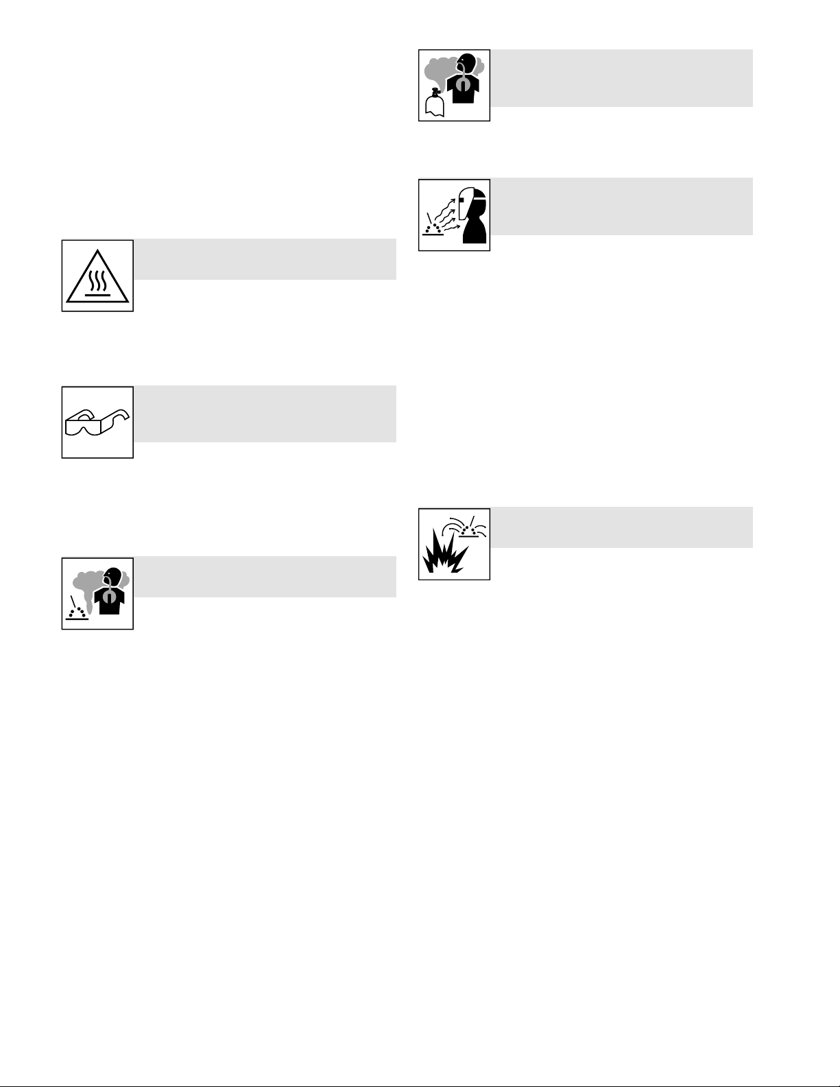
l S’assurer que tous les panneaux et couvercles sont correctement
en place.
l Fixer le câble de retour de façon à obtenir un bon contact métal-
métal avec la pièce à souder ou la table de travail, le plus près
possible de la soudure.
l Isoler la pince de masse quand pas mis à la pièce pour éviter le
contact avec tout objet métallique.
l Ne pas raccorder plus d’une électrode ou plus d’un câble de
masse à une même borne de sortie de soudage. Débrancher le
câble pour le procédé non utilisé.
l Utiliser une protection différentielle lors de l’utilisation d’un équipe-
ment auxiliaire dans des endroits humides ou mouillés.
LES PIÈCES CHAUDES peuvent
provoquer des brûlures.
l Ne pas toucher des parties chaudes à mains nues.
l Prévoir une période de refroidissement avant de
travailler à l’équipement.
l Ne pas toucher aux pièces chaudes, utiliser les outils recomman-
dés et porter des gants de soudage et des vêtements épais pour
éviter les brûlures.
DES PIECES DE METAL ou DES
SALETES peuvent provoquer des
blessures dans les yeux.
l Le soudage, l’écaillement, le passage de la pièce
à la brosse en fil de fer, et le meulage génèrent
des étincelles et des particules métalliques volantes. Pendant la
période de refroidissement des soudures, elles risquent de projeter du laitier.
l Porter des lunettes de sécurité avec écrans latéraux ou un écran
facial.
LES FUMÉES ET LES GAZ peuvent
être dangereux.
Le soudage génère des fumées et des gaz. Leur
inhalation peut être dangereux pour votre santé.
l Eloigner votre tête des fumées. Ne pas respirer les fumées.
l À l’intérieur, ventiler la zone et/ou utiliser une ventilation forcée au
niveau de l’arc pour l’évacuation des fumées et des gaz de soudage. Pour déterminer la bonne ventilation, il est recommandé de
procéder à un prélèvement pour la composition et la quantité de
fumées et de gaz auxquelles est exposé le personnel.
l Si la ventilation est médiocre, porter un respirateur anti-vapeurs
approuvé.
l Lire et comprendre les fiches de données de sécurité et les ins-
tructions du fabricant concernant les adhésifs, les revêtements,
les nettoyants, les consommables, les produits de refroidissement, les dégraisseurs, les flux et les métaux.
l Travailler dans un espace fermé seulement s’il est bien ventilé ou
en portant un respirateur à alimentation d’air. Demander toujours
à un surveillant dûment formé de se tenir à proximité. Des fumées
et des gaz de soudage peuvent déplacer l’air et abaisser le niveau
d’oxygène provoquant des blessures ou des accidents mortels.
S’assurer que l’air de respiration ne présente aucun danger.
l Ne pas souder dans des endroits situés à proximité d’opérations
de dégraissage, de nettoyage ou de pulvérisation. La chaleur et
les rayons de l’arc peuvent réagir en présence de vapeurs et former des gaz hautement toxiques et irritants.
l Ne pas souder des métaux munis d’un revêtement, tels que l’acier
galvanisé, plaqué en plomb ou au cadmium à moins que le revêtement n’ait été enlevé dans la zone de soudure, que l’endroit soit
bien ventilé, et en portant un respirateur à alimentation d’air. Les
revêtements et tous les métaux renfermant ces éléments peuvent
dégager des fumées toxiques en cas de soudage.
LES ACCUMULATIONS DE GAZ
risquent de provoquer des blessures
ou même la mort.
l Fermer l’alimentation du gaz comprimé en cas de
non utilisation.
l Veiller toujours à bien aérer les espaces confinés ou se servir d’un
respirateur d’adduction d’air homologué.
LES RAYONS DE L’ARC peuvent
provoquer des brûlures dans les
yeux et sur la peau.
Le rayonnement de l’arc du procédé de soudage
génère des rayons visibles et invisibles intenses
(ultraviolets et infrarouges) susceptibles de provoquer des brûlures
dans les yeux et sur la peau. Des étincelles sont projetées pendant le
soudage.
l Porter un casque de soudage approuvé muni de verres filtrants
approprié pour protéger visage et yeux pendant le soudage (voir
ANSI Z49.1 et Z87.1 énuméré dans les normes de sécurité).
l Porter des lunettes de sécurité avec écrans latéraux même sous
votre casque.
l Avoir recours à des écrans protecteurs ou à des rideaux pour pro-
téger les autres contre les rayonnements les éblouissements et
les étincelles ; prévenir toute personne sur les lieux de ne pas regarder l’arc.
l Porter une protection corporelle en cuir ou des vêtements ignifu-
ges (FRC). La protection du corps comporte des vêtements sans
huile, comme des gants de cuir, une chemise solide, des pantalons sans revers, des chaussures hautes et une casquette.
LE SOUDAGE peut provoquer un
incendie ou une explosion.
Le soudage effectué sur des conteneurs fermés
tels que des réservoirs, tambours ou des conduites
peut provoquer leur éclatement. Des étincelles
peuvent être projetées de l’arc de soudure. La projection d’étincelles,
des pièces chaudes et des équipements chauds peut provoquer des
incendies et des brûlures. Le contact accidentel de l’électrode avec
des objets métalliques peut provoquer des étincelles, une explosion,
un surchauffement ou un incendie. Avant de commencer le soudage,
vérifier et s’assurer que l’endroit ne présente pas de danger.
l Déplacer toutes les substances inflammables à une distance de
10,7 m de l’arc de soudage. En cas d’impossibilité les recouvrir
soigneusement avec des protections homologués.
l Ne pas souder dans un endroit là où des étincelles peuvent tom-
ber sur des substances inflammables.
l Se protéger et d’autres personnes de la projection d’étincelles et
de métal chaud.
l Des étincelles et des matériaux chauds du soudage peuvent faci-
lement passer dans d’autres zones en traversant de petites fissures et des ouvertures.
l Surveiller tout déclenchement d’incendie et tenir un extincteur à
proximité.
l Le soudage effectué sur un plafond, plancher, paroi ou séparation
peut déclencher un incendie de l’autre côté.
l Ne pas couper ou souder des jantes ou des roues. Les pneus peu-
vent exploser s’ils sont chauffés. Les jantes et les roues réparées
peuvent défaillir. Voir OSHA 29 CFR 1910.177 énuméré dans les
normes de sécurité.
l Ne pas effectuer le soudage sur des conteneurs fermés tels que
des réservoirs, tambours, ou conduites, à moins qu’ils n’aient été
préparés correctement conformément à AWS F4.1 (voir les Normes de Sécurité).
l Ne pas souder là où l’air ambiant pourrait contenir des poussières,
gaz ou émanations inflammables (vapeur d’essence, par
exemple).
OM-294120 Page 6
Page 12
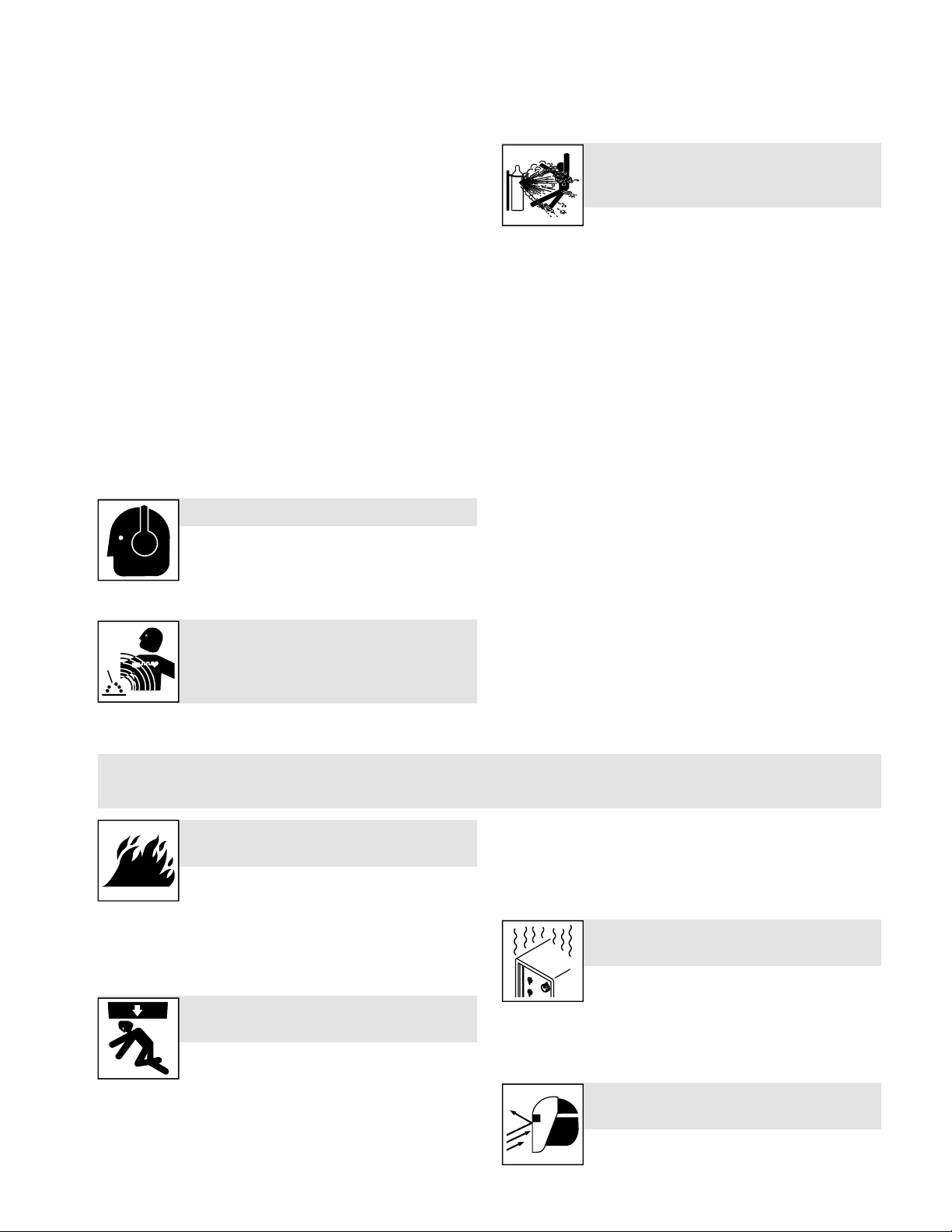
l Brancher le câble de masse sur la pièce le plus près possible de
la zone de soudage pour éviter le transport du courant sur une longue distance par des chemins inconnus éventuels en provoquant
des risques d’électrocution, d’étincelles et d’incendie.
l Ne pas utiliser le poste de soudage pour dégeler des conduites
gelées.
l En cas de non utilisation, enlever la baguette d’électrode du porte-
électrode ou couper le fil à la pointe de contact.
l Porter une protection corporelle en cuir ou des vêtements ignifu-
ges (FRC). La protection du corps comporte des vêtements sans
huile, comme des gants de cuir, une chemise solide, des pantalons sans revers, des chaussures hautes et une casquette.
l Avant de souder, retirer toute substance combustible de vos po-
ches telles qu’un allumeur au butane ou des allumettes.
l Une fois le travail achevé, assurez-vous qu’il ne reste aucune
trace d’étincelles incandescentes ni de flammes.
l Utiliser exclusivement des fusibles ou coupe-circuits appropriés.
Ne pas augmenter leur puissance; ne pas les ponter.
l Suivre les recommandations dans OSHA 1910.252 (a) (2) (iv) et
NFPA 51B pour les travaux à chaud et avoir de la surveillance et
un extincteur à proximité.
l Lire et comprendre les fiches de données de sécurité et les ins-
tructions du fabricant concernant les adhésifs, les revêtements,
les nettoyants, les consommables, les produits de refroidissement, les dégraisseurs, les flux et les métaux.
Le BRUIT peut endommager l’ouïe.
Le bruit des processus et des équipements peut
affecter l’ouïe.
l Porter des protections approuvées pour les oreilles
si le niveau sonore est trop élevé.
Les CHAMPS
ÉLECTROMAGNÉTIQUES (CEM)
peuvent affecter les implants
médicaux.
l Les porteurs de stimulateurs cardiaques et autres
implants médicaux doivent rester à distance.
l Les porteurs d’implants médicaux doivent consulter leur médecin
et le fabricant du dispositif avant de s’approcher de la zone où se
déroule du soudage à l’arc, du soudage par points, du gougeage,
de la découpe plasma ou une opération de chauffage par
induction.
Si des BOUTEILLES sont
endommagées, elles pourront
exploser.
Des bouteilles de gaz comprimé protecteur
contiennent du gaz sous haute pression. Si une
bouteille est endommagée, elle peut exploser. Du fait que les bouteilles de gaz font normalement partie du procédé de soudage, les manipuler avec précaution.
l Protéger les bouteilles de gaz comprimé d’une chaleur excessive,
des chocs mécaniques, des dommages physiques, du laitier, des
flammes ouvertes, des étincelles et des arcs.
l Placer les bouteilles debout en les fixant dans un support station-
naire ou dans un porte-bouteilles pour les empêcher de tomber ou
de se renverser.
l Tenir les bouteilles éloignées des circuits de soudage ou autres
circuits électriques.
l Ne jamais placer une torche de soudage sur une bouteille à gaz.
l Une électrode de soudage ne doit jamais entrer en contact avec
une bouteille.
l Ne jamais souder une bouteille pressurisée - risque d’explosion.
l Utiliser seulement des bouteilles de gaz comprimé, régulateurs,
tuyaux et raccords convenables pour cette application spécifique;
les maintenir ainsi que les éléments associés en bon état.
l Tourner le dos à la sortie de vanne lors de l’ouverture de la vanne
de la bouteille. Ne pas se tenir devant ou derrière lerégulateur lors
de l’ouverture de la vanne.
l Maintenir le chapeau de protection sur la soupape, sauf en cas
d’utilisation ou de branchement de la bouteille.
l Utilisez les équipements corrects, les bonnes procédures et suffi-
samment de personnes pour soulever, déplacer et transporter les
bouteilles.
l Lire et suivre les instructions sur les bouteilles de gaz comprimé,
l’équipement connexe et le dépliant P-1 de la CGA (Compressed
Gas Association) mentionné dans les principales normes de
sécurité.
2-3. Symboles de dangers supplémentaires en relation avec l’installation, le
fonctionnement et la maintenance
Risque D’INCENDIE OU
D’EXPLOSION.
l Ne pas placer l’appareil sur, au-dessus ou à proxi-
mité de surfaces inflammables.
l Ne pas installer l’appareil à proximité de produits
inflammables
l Ne pas surcharger l’installation électrique – s’assurer que l’alimen-
tation est correctement dimensionné et protégé avant de mettre
l’appareil en service.
LA CHUTE DE L’ÉQUIPEMENT peut
provoquer des blessures.
l Utiliser l’anneau de levage uniquement pour soule-
ver l’appareil, NON PAS les organes de roulement,
les bouteilles de gaz ou tout autre accessoire.
l Utilisez les procédures correctes et des équipements d’une capa-
cité appropriée pour soulever et supporter l’appareil.
l En utilisant des fourches de levage pour déplacer l’unité, s’assurer
que les fourches sont suffisamment longues pour dépasser du
côté opposé de l’appareil.
OM-294120 Page 7
l Tenir l’équipement (câbles et cordons) à distance des véhicules
mobiles lors de toute opération en hauteur.
l Suivre les consignes du Manuel des applications pour l’équation
de levage NIOSH révisée (Publication Nº94– 110) lors du levage
manuelle de pièces ou équipements lourds.
L’EMPLOI EXCESSIF peut
SURCHAUFFER L’ÉQUIPEMENT.
l Laisser l’équipement refroidir ; respecter le facteur
de marche nominal.
l Réduire le courant ou le cycle opératoire avant de
recommancer le soudage.
l Ne pas obstruer les passages d’air du poste.
LES ÉTINCELLES PROJETÉES
peuvent provoquer des blessures.
l Porter un écran facial pour protéger le visage et
les yeux.
Page 13
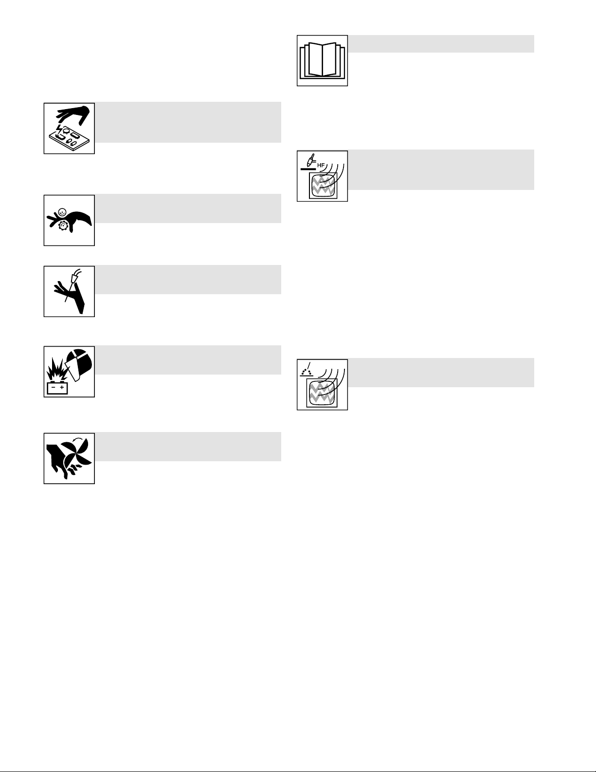
l Affûter l'électrode au tungstène uniquement à la meuleuse dotée
de protecteurs. Cette manœuvre est à exécuter dans un endroit
sûr lorsque l'on porte l'équipement homologué de protection du visage, des mains et du corps.
l Les étincelles risquent de causer un incendie - éloigner toute sub-
stance inflammable.
LES CHARGES
ÉLECTROSTATIQUES peuvent
endommager les circuits imprimés.
l Établir la connexion avec la barrette de terre
AVANT de manipuler des cartes ou des pièces.
l Utiliser des pochettes et des boîtes antistatiques pour stocker, dé-
placer ou expédier des cartes de circuits imprimes.
Les PIÈCES MOBILES peuvent
causer des blessures.
l Ne pas s’approcher des organes mobiles.
l Ne pas s’approcher des points de coincement tels
que des rouleaux de commande.
LES FILS DE SOUDAGE peuvent
provoquer des blessures.
l Ne pas appuyer sur la gachette avant d’en avoir
reçu l’instruction.
l Ne pas diriger le pistolet vers soi, d’autres person-
nes ou toute pièce mécanique en engageant le fil de soudage.
L’EXPLOSION DE LA BATTERIE peut
provoquer des blessures.
l Ne pas utiliser l’appareil de soudage pour charger
des batteries ou faire démarrer des véhicules à
l’aide de câbles de démarrage, sauf si l’appareil
dispose d’une fonctionnalité de charge de batterie destinée à cet
usage.
Les PIÈCES MOBILES peuvent
causer des blessures.
l S’abstenir de toucher des organes mobiles tels
que des ventilateurs.
l Maintenir fermés et verrouillés les portes, pan-
neaux, recouvrements et dispositifs de protection.
l Lorsque cela est nécessaire pour des travaux d’entretien et de dé-
pannage, faire retirer les portes, panneaux, recouvrements ou dispositifs de protection uniquement par du personnel qualifié.
l Remettre les portes, panneaux, recouvrements ou dispositifs de
protection quand l’entretien est terminé et avant de rebrancher l’alimentation électrique.
LIRE LES INSTRUCTIONS.
l Lire et appliquer les instructions sur les étiquettes
et le Mode d’emploi avant l’installation, l’utilisation
ou l’entretien de l’appareil. Lire les informations de
sécurité au début du manuel et dans chaque
section.
l N’utiliser que des pièces de remplacement provenant du fabricant.
l Effectuer l’installation, l’entretien et toute intervention selon les
manuels d’utilisateurs, les normes nationales, provinciales et de
l’industrie, ainsi que les codes municipaux.
LE RAYONNEMENT HAUTE
FRÉQUENCE (H.F.) risque de
provoquer des interférences.
l Le rayonnement haute fréquence (H.F.) peut pro-
voquer des interférences avec les équipements de
radio-navigation et de communication, les services de sécurité et
les ordinateurs.
l Demander seulement à des personnes qualifiées familiarisées
avec des équipements électroniques de faire fonctionner
l’installation.
l L’utilisateur est tenu de faire corriger rapidement par un électricien
qualifié les interférences résultant de l’installation.
l Si le FCC signale des interférences, arrêter immédiatement
l’appareil.
l Effectuer régulièrement le contrôle et l’entretien de l’installation.
l Maintenir soigneusement fermés les portes et les panneaux des
sources de haute fréquence, maintenir les éclateurs à une distance correcte et utiliser une terre et un blindage pour réduire les
interférences éventuelles.
LE SOUDAGE À L’ARC risque de
provoquer des interférences.
l L’énergie électromagnétique risque de provoquer
des interférences pour l’équipement électronique
sensible tel que les ordinateurs et l’équipement
commandé par ordinateur tel que les robots.
l Veiller à ce que tout l’équipement de la zone de soudage soit
compatible électromagnétiquement.
l Pour réduire la possibilité d’interférence, maintenir les câbles de
soudage aussi courts que possible, les grouper, et les poser aussi
bas que possible (ex. par terre).
l Veiller à souder à une distance de 100 mètres de tout équipement
électronique sensible.
l Veiller à ce que ce poste de soudage soit posé et mis à la terre
conformément à ce mode d’emploi.
l En cas d’interférences après avoir pris les mesures précédentes,
il incombe à l’utilisateur de prendre des mesures supplémentaires
telles que le déplacement du poste, l’utilisation de câbles blindés,
l’utilisation de filtres de ligne ou la pose de protecteurs dans la
zone de travail.
OM-294120 Page 8
Page 14

2-4. Proposition californienne 65 Avertissements
AVERTISSEMENT – Ce produit peut vous exposer à des produits chimiques tels que le plomb, reconnus par l’État de
Californie comme cancérigènes et sources de malformations ou d’autres troubles de la reproduction.
Pour plus d’informations, consulter www.P65Warnings.ca.gov.
2-5. Principales normes de sécurité
Safety in Welding, Cutting, and Allied Processes, American Welding
Society standard ANSI Standard Z49.1. Website: http://www.aws.org.
Safe Practice For Occupational And Educational Eye And Face Protection, ANSI Standard Z87.1, from American National Standards In-
stitute. Website: www.ansi.org.
Safe Practices for the Preparation of Containers and Piping for Welding and Cutting, American Welding Society Standard AWS F4.1.
Website: http://www.aws.org.
National Electrical Code, NFPA Standard 70 from National Fire Protection Association. Website: www.nfpa.org.
Safe Handling of Compressed Gases in Cylinders, CGA Pamphlet P1 from Compressed Gas Association. Website: www.cganet.com.
Safety in Welding, Cutting, and Allied Processes, CSA Standard
W117.2 from Canadian Standards Association. Website: www.
csagroup.org.
Standard for Fire Prevention During Welding, Cutting, and Other Hot
Work, NFPA Standard 51B from National Fire Protection Association.
Website: www.nfpa.org.
OSHA, Occupational Safety and Health Standards for General Industry, Title 29, Code of Federal Regulations (CFR), Part 1910.177 Subpart N, Part 1910 Subpart Q, and Part 1926, Subpart J. Website:
www.osha.gov.
OSHA Important Note Regarding the ACGIH TLV, Policy Statement
on the Uses of TLVs and BEIs. Website: www.osha.gov.
Applications Manual for the Revised NIOSH Lifting Equation from the
National Institute for Occupational Safety and Health (NIOSH). Website: www.cdc.gov/NIOSH.
SOM_fre 2022–01
2-6. Informations relatives aux CEM
Le courant électrique qui traverse tout conducteur génère des
champs électromagnétiques (CEM) à certains endroits. Le courant issu d’un soudage à l’arc (et de procédés connexes, y compris le soudage par points, le gougeage, le découpage plasma et les opérations
de chauffage par induction) crée un champ électromagnétique (CEM)
autour du circuit de soudage. Les champs électromagnétiques produits peuvent causer interférence à certains implants médicaux,
p. ex. les stimulateurs cardiaques. Des mesures de protection pour
les porteurs d’implants médicaux doivent être prises: par exemple,
des restrictions d’accès pour les passants ou une évaluation individuelle des risques pour les soudeurs. Tous les soudeurs doivent appliquer les procédures suivantes pour minimiser l’exposition aux CEM
provenant du circuit de soudage:
1. Rassembler les câbles en les torsadant ou en les attachant avec
du ruban adhésif ou avec une housse.
2. Ne pas se tenir au milieu des câbles de soudage. Disposer les câbles d’un côté et à distance de l’opérateur.
3. Ne pas courber et ne pas entourer les câbles autour de votre
corps.
4. Maintenir la tête et le torse aussi loin que possible du matériel du
circuit de soudage.
5. Connecter la pince sur la pièce aussi près que possible de la
soudure.
6. Ne pas travailler à proximité d’une source de soudage, ni s’asseoir
ou se pencher dessus.
7. Ne pas souder tout en portant la source de soudage ou le
dévidoir.
En ce qui concerne les implants médicaux :
Les porteurs d’implants doivent d’abord consulter leur médecin avant
de s’approcher des opérations de soudage à l’arc, de soudage par
points, de gougeage, du coupage plasma ou de chauffage par induction. Si le médecin approuve, il est recommandé de suivre les procédures précédentes.
OM-294120 Page 9
Page 15
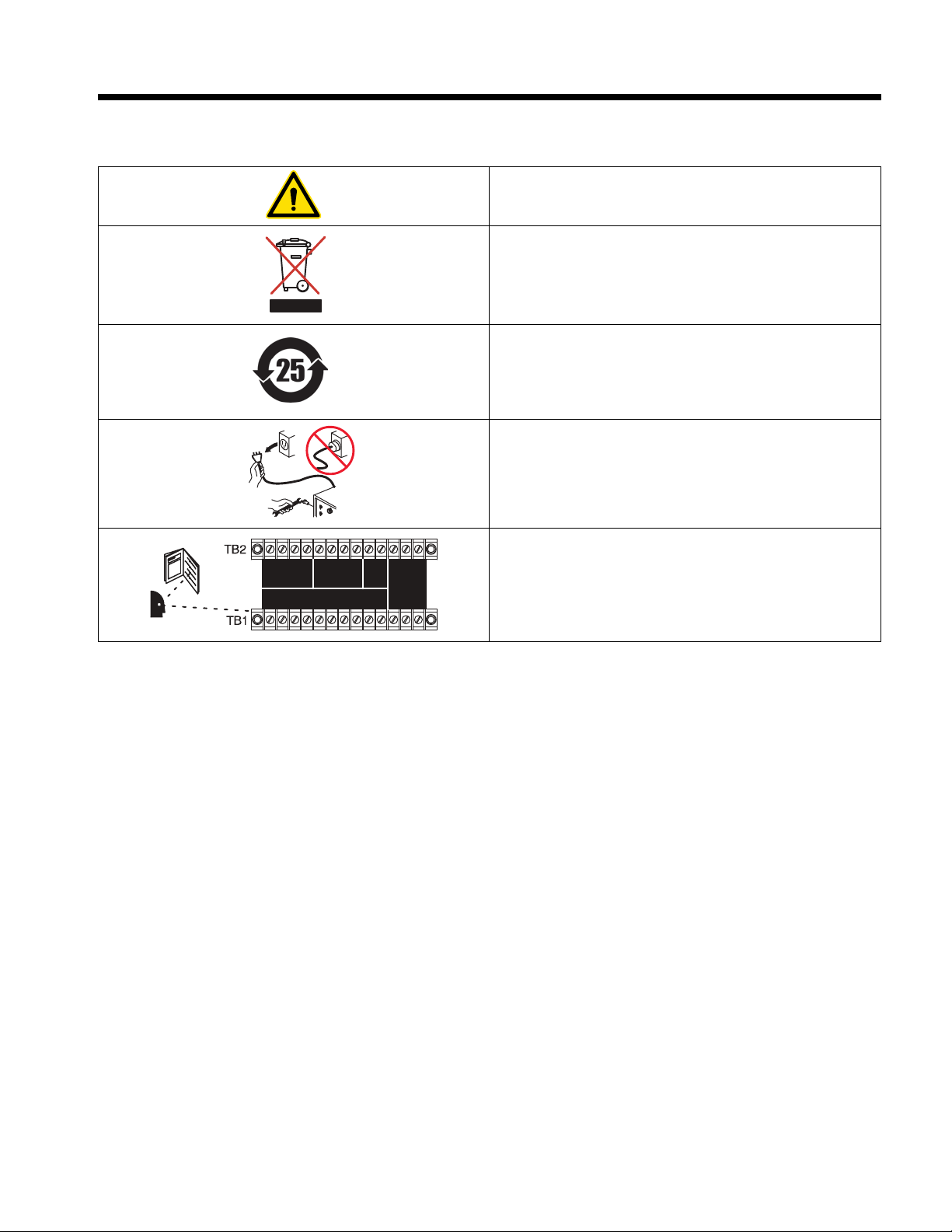
Complete Parts List is available at www.MillerWelds.com
Warning! Watch Out! There are possible hazards as shown by the symbols.
Safe1 2012 05
Do not discard product (where applicable) with general waste.
Reuse or recycle Waste Electrical and Electronic Equipment (WEEE) by disposing at a designated collection
facility.
Contact your local recycling office or your local distributor for further information.
Safe37 2017 04
/
<12.4 V
+ +
Read Owner’s Manual for battery maintenance information.
Safe117 2014 06
Do not spray water on electrical parts, including Engine Control Unit (ECU).
Safe 118 2014 10
Recycle or dispose of used coolant in an environmentally safe way.
Safe119 2015 05
Hot Parts can burn. Do not touch hot parts bare-handed. Allow cooling period before handling parts or equip-
ment.
Safe120 2015 11
Connect Green Or Green/Yellow grounding conductor to ground terminal first.
Connect input conductors (U/L1, V/L2, W/L3) to line terminals.
Safe121 2016 04
Use lifting eye to lift unit and properly installed units only.
Use a proper cart to move unit.
Safe122 2016 04
Environmental
Protection Use Period (China)
Safe123 2016 06
ome symbols are found only on CE products.
Warning! Watch Out! There are possible hazards as shown by the symbols.
S
afe1 201205
Do not discard product (where applicable) with general waste.
Reuse or recycle Waste Electrical and Electronic Equipment (WEEE) by disposing at a designated collection
facility.
Contact your local recycling office or your local distributor for further information.
S
afe37 201704
Wear dry insulating gloves. Do not touch electrode with bare hand. Do not wear wet or damaged gloves.
Safe2 2017 04
Protect yourself from electric shock by insulating yourself from work and ground.
Safe3 2017 04
Protect yourself from electric shock by insulating yourself from work and ground.
Safe4 2017 04
Disconnect input plug or power before working on machine.
Safe5 2017 04
Drive rolls can injure fingers. Welding wire and drive parts are at welding voltage during operation keep hands
and metal objects away.
Safe95 2012 05
Always connect green, Or green with yellow stripe, wire to supply grounding terminal.
Connect black, white, and red wires (L1, L2, L3) to line terminals.
Safe101 2012 05
GND/PE, Ground/Protective Earth
Safe 114 2013 04
Safe116 2014 02
Read Owner’s Manual for terminal strip connection information.
F
SECTION 3 – DEFINITIONS
3-1. Additional Safety Symbol Definitions
Some symbols are found only on CE products.
F
Warning! Watch Out! There are possible hazards as shown by the
symbols.
Do not discard product (where applicable) with general waste.
Reuse or recycle Waste Electrical and Electronic Equipment (WEEE)
by disposing at a designated collection facility.
Contact your local recycling office or your local distributor for further
information.
Environmental Protection Use Period (China)
Disconnect input plug or power before working on machine.
Read Owner's Manual for terminal strip connection information.
OM-294120 Page 10
Page 16
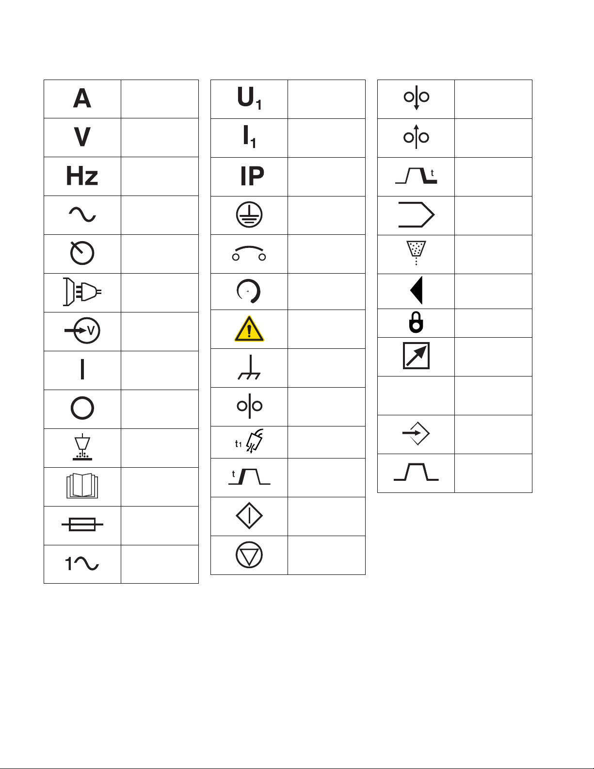
Complete Parts List is available at www.MillerWelds.com
%
Percent
Increase
t (sec)
F
3-2. Miscellaneous Symbols And Definitions
Some symbols are found only on CE products.
F
Amperage
Voltage
Hertz
Alternating Current
(AC)
Panel/Local
Line Connection
Input Voltage
On
Primary Voltage
Primary Current
Degree of
Protection
Protective Earth
(Ground)
Circuit Breaker
Increase/Decrease
Of Quantity
Caution
Frame Or Chassis
Wire Feed Inch
Down
Wire Feed Inch Up
Crater Time
Program
Flux
Display Push Button
Lock
Remote
Off
Submerged Arc
Welding (SAW)
Read Operators
Manual
Fuse
Single Phase
Wire Feed
Preflux Timer
Start Time
Start of Action
Stop of Action
Time
Set Up
Sequence
OM-294120 Page 11
Page 17

Complete Parts List is available at www.MillerWelds.com
F
SECTION 4 – SPECIFICATIONS
4-1. Serial Number And Rating Label Location
A. Serial Number And Rating Label Location For SubArc Motor Control Digital
The serial number and rating information for the motor control digital is located on the right side. Use rating label to determine input power requirements and/or rated output. For future reference, write serial number in space provided on back cover of this manual.
B. Serial Number And Rating Label Location For SubArc Remote Pendant Digital
The serial number and rating information for the remote pendant digital is located on the back plate. Use rating label to determine input power requirements. For future reference, write serial number in space provided on back cover of this manual.
4-2. Software Licensing Agreement
The End User License Agreement and any third-party notices and terms and conditions pertaining to third-party software can be found at
https://www.millerwelds.com/eula and are incorporated by reference herein.
4-3. Information About Default Weld Parameters And Settings
NOTICE – Each welding application is unique. Although certain Miller Electric products are designed to determine and default to certain typical
welding parameters and settings based upon specific and relatively limited application variables input by the end user, such default settings are
for reference purposes only; and final weld results can be affected by other variables and application-specific circumstances. The appropriateness of all parameters and settings should be evaluated and modified by the end user as necessary based upon application-specific requirements. The end user is solely responsible for selection and coordination of appropriate equipment, adoption or adjustment of default weld
parameters and settings, and ultimate quality and durability of all resultant welds. Miller Electric expressly disclaims any and all implied warranties including any implied warranty of fitness for a particular purpose.
4-4. Specifications
A. Specifications For SubArc Motor Control Digital
Specifications Description
Type of power source Single-Phase
Overall dimensions including knobs, receptacles, etc. Height: 11.5 in. (292 mm)
Weight Net: 12.9 lbs (5.8 kg)
Weld voltage and amperage capacity (AC or DC) 0 to 100 Volts
Wire feed speed range Dependent on motor in system
24 VAC, 25 Amps
50/60 Hz
Width: 12.5 in. (318 mm)
Depth: 7.0 in. (178 mm)
0 to 1500 Amperes
B. Specifications For SubArc Remote Pendant Digital
Specifications Description
Type of power source Single-Phase
Overall dimensions including knobs, receptacles, etc. Height: 3.0 in. (76.2 mm)
Weight Net: 2.7 lbs (1.2 kg)
Weld voltage and amperage capacity (AC or DC) 0 to 100 Volts
Wire feed speed range Dependent on motor in system
42 VDC, 1 Amps
Width: 10.6 in. (269.2 mm)
Depth: 3.3 in. (84 mm)
0 to 1500 Amperes
OM-294120 Page 12
Page 18
Complete Parts List is available at www.MillerWelds.com
Warning! Watch Out! There are possible hazards as shown by the symbols.
Safe1 2012 05
Do not discard product (where applicable) with general waste.
Reuse or recycle Waste Electrical and Electronic Equipment (WEEE) by disposing at a designated collection
facility.
Contact your local recycling office or your local distributor for further information.
Safe37 2017 04
F
4-5. Environmental Specifications
A. IP Rating
IP Rating
IP23
This equipment is designed for outdoor use.
B. Information On Electromagnetic Compatibility (EMC)
This Class A equipment is not intended for use in residential locations where the electrical power is provided by the public
low-voltage supply system. There can be potential difficulties in ensuring electromagnetic compatibility in those locations,
due to conducted as well as radiated disturbances.
C. Temperature Specifications
Operating Temperature Range* Storage/Transportation Temperature Range
14 to 104°F (-10 to 40°C) -4 to 131°F (-20 to 55°C)
*Output is derated at temperatures above 104°F (40°C).
D. EU Ecodesign Information
Do not discard product (where applicable) with general waste.
Reuse or recycle Waste Electrical and Electronic Equipment (WEEE)
by disposing at a designated collection facility.
Contact your local recycling office or your local distributor for further
information.
Critical raw materials possibly present in indicative amounts higher than 1 gram at component level
Component Critical Raw Material
Printed circuit boards Baryte, Bismuth, Cobalt, Gallium, Germanium, Hafnium, Indium, Heavy Rare Earth, Light Rare
Plastic components Antimony, Baryte
Electrical and electronic components Antimony, Beryllium, Magnesium
Metal components Beryllium, Cobalt, Magnesium, Tungsten, Vanadium
Cables and cable assemblies Borate, Antimony, Baryte, Beryllium, Magnesium
Display panels Gallium, Indium, Heavy Rare Earth, Light Rare Earth,Niobium, Platinum Group Metals, Scandium
Batteries Fluorspar, Heavy Rare Earth, Light Rare Earth, Magnesium
Earth, Niobium, Platinum Group Metals, Scandium, Silicon Metal, Tantalum, Vanadium
OM-294120 Page 13
Page 19
Complete Parts List is available at www.MillerWelds.com
/
<12.4 V
+ +
Read Owner’s Manual for battery maintenance information.
Safe117 2014 06
Do not spray water on electrical parts, including Engine Control Unit (ECU).
Safe 118 2014 10
Recycle or dispose of used coolant in an environmentally safe way.
Safe119 2015 05
Hot Parts can burn. Do not touch hot parts bare-handed. Allow cooling period before handling parts or equip-
ment.
Safe120 2015 11
Connect Green Or Green/Yellow grounding conductor to ground terminal first.
Connect input conductors (U/L1, V/L2, W/L3) to line terminals.
Safe121 2016 04
Use lifting eye to lift unit and properly installed units only.
Use a proper cart to move unit.
Safe122 2016 04
Environmental
Protection Use Period (China)
Safe123 2016 06
F
E. China EEP Hazardous Substance Information
中国电器电子产品中有害物质的名称及含量
China EEP Hazardous Substance Information
部件名称
Component
Name
(如果适用)
(if applicable)
黄铜和铜部件
Brass and Copper Parts
耦合装置
Coupling Devices
开关装置
Switching
Devices
线缆和线缆配件
Cable and Cable
Accessories
电池
Batteries
本表格依据中国SJ/T 11364的规定编制.
This table is prepared in accordance with China SJ/T 11364.
O:
表示该有害物质在该部件所有均质材料中的含量均在中国GB/T26572规定的限量要求以下.
Indicates that the concentration of the Hazardous Substance in all homogeneous materials of the part is below the relevant threshold of China
GB/T 26572.
X:
表示该有害物质至少在该部件的某一均质材料中的含量超出中国GB/T26572规定的限量要求.
Indicates that the concentration of the Hazardous Substance in at least one homogeneous material of the part is above the relevant threshold
of China GB/T 26572.
器电子产品的环保使用期限依据中国SJ/Z11388的规定确定.
The EFUP value of this EEP is defined in accordance with China SJ/Z 11388.
有害物质
Hazardous Substance
铅
Pb
X O O O O O
X O O O O O
O O X O O O
X O O O O O
X O O O O O
汞
Hg
镉
Cd
六价铬
Cr6
多溴联苯
PBB
多溴二苯醚
PBDE
OM-294120 Page 14
Page 20

Complete Parts List is available at www.MillerWelds.com
F
4-6. SubArc System Compatibility
The following power source and accessory models are compatible. The interface will automatically detect the power source and wire drive type
connected.
Only like power source models can be connected with parallel or tandem cables.
F
Power Sources:
907620 - SubArc AC/DC 1000 Digital
907621 - SubArc AC/DC 1250 Digital
907622 - SubArc DC 650 Digital
907923 - SubArc DC 800 Digital
907624 - SubArc DC 1000 Digital
907625 - SubArc DC 1250 Digital
Interfaces:
300936 - SubArc Interface Digital
300937 - SubArc Interface Analog
301423 - SubArc Tractor Interface Digital
301424 - SubArc Remote Pendant Digital
301425 - SubArc Motor Control Digital
Wire Drives:
300938 - SubArc Wire Drive 400 Digital Low Voltage
301596 − SubArc Wire Drive 200 Digital Low Voltage
300938001 - SubArc Wire Drive 400 Digital Low Voltage For Tractors
300938002 − SubArc Wire Drive 400 Digital Low Voltage For SPWS
300939 - SubArc Strip Drive 100 Digital Low Voltage
300940 - SubArc Strip Drive 100 Digital Low Voltage w/Mounting Bracket
300941 - SubArc Wire Drive 780 Digital Low Voltage
Flux Hopper:
300942 - SubArc Flux Hopper Digital Low Voltage
301445 − SubArc Manual Flux Hopper
OM-294120 Page 15
Page 21

Complete Parts List is available at www.MillerWelds.com
F
4-7. Power Source Compatibility With 14-Pin To SubArc Digital Converter
The following power sources are compatible with the 14-Pin To SubArc Digital Converter. Will function with current and legacy Miller Big Blues
500, 600, and 800 without 120VAC supplied from the 14-Pin receptacle.
If uncertain whether a 14-Pin To SubArc is needed, contact Miller Customer Service.
F
CV+C is NOT functional with the 14-Pin To SubArc Digital Converter.
F
The current base model Big Blues listed below will function with SubArc Digital Accessories. Derivative Big Blue models are also compatible.
Power Sources:
907736 - Big Blue 500 Pro
907737 - Big Blue 600 Pro
907750 - Big Blue 600 Air Pack
907751 - Big Blue 800 Duo Pro
907752 - Big Blue 800 Duo Air Pak
903254 - Dimension 452
903255 - Dimension 452
903379 - Dimension 652
903650 - Dimension 1000
907617 - Dimension 650
907618 - Dimension 650
903377 - Deltaweld 452
903394 - Deltaweld 452
903396 - Deltaweld 652
907338 - SubArc DC 650
907344 - SubArc DC 800
907342 - SubArc DC 1000
907343 - SubArc DC 1250
903530 - Summit Arc 1000
903570 - Summit Arc 1250
OM-294120 Page 16
Page 22
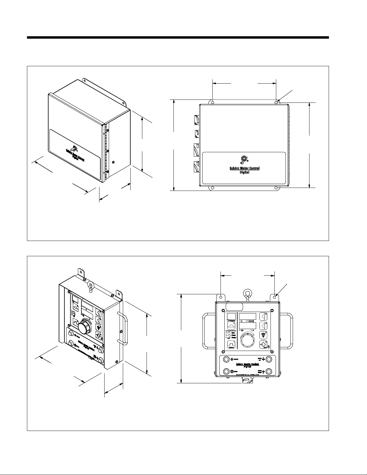
Complete Parts List is available at www.MillerWelds.com
277879-A
12 in.
(305 mm)
7 in.*
(178 mm)
10-1/4 in.
(260 mm)
11-1/2 in.
(292 mm)
8 in.
(203 mm)
10-3/4 in.
(273 mm)
5/16 in.
(7.9 mm)
Dia. 4 Holes
277880-A
9/32 in.
(7.1 mm)
Dia. 2 Holes
6-1/2 in.
(165 mm)
10-1/2 in.
(267 mm)
9 in.
(229 mm)
2-1/4 in.
(57 mm)
5-1/2 in.
(140 mm)
F
SECTION 5 – INSTALLATION
5-1. Dimensions And Mounting Hole Layout
A. SubArc Motor Control Digital Dimensions And Mounting Hole Layout
* Includes front panel knobs/switches
B. SubArc Remote Pendant Digital Dimensions And Mounting Hole Layout
OM-294120 Page 17
Page 23
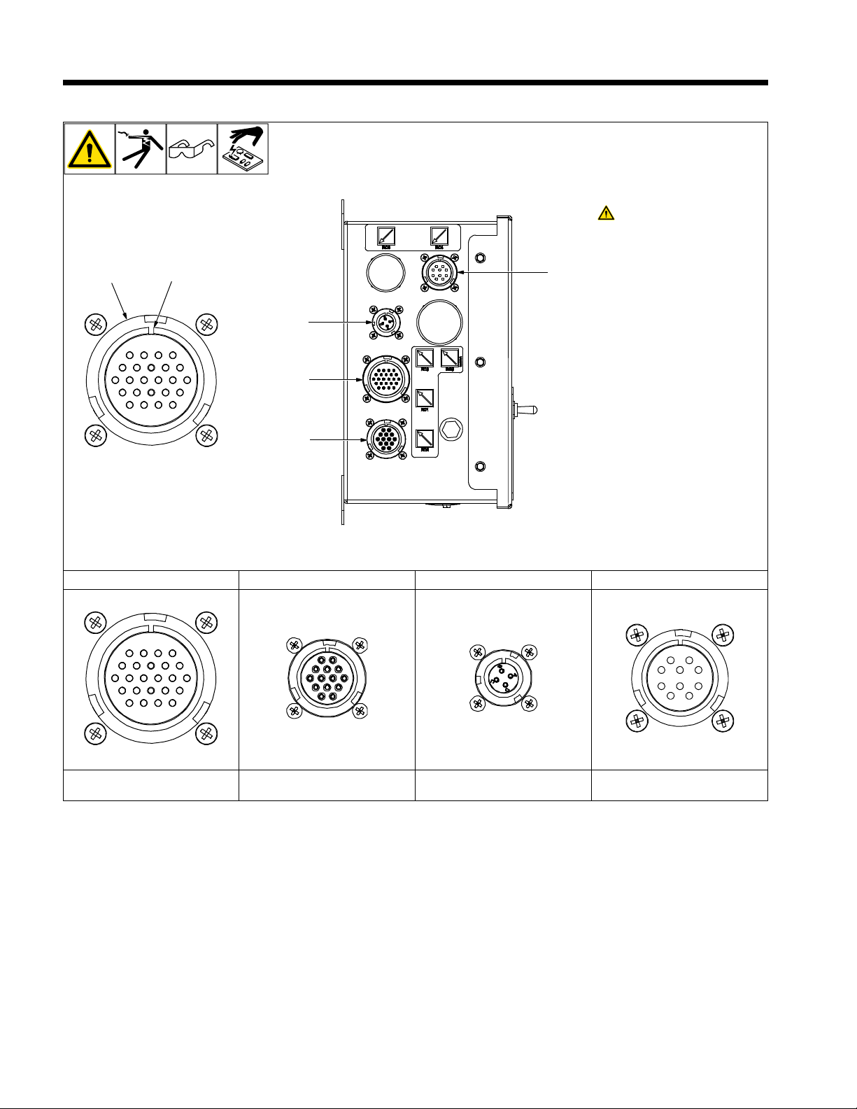
SECTION 6 – SYSTEM CONNECTIONS
277881-B
3
4
5
1
2
6
6-1. Left Side Panel Connections For SubArc Motor Control Digital
Turn Off welding power
source and weld control
and disconnect input
power before opening access door.
1 Receptacle
2 Keyway
3 Receptacle RC3
Connection to flux hopper.
4 Receptacle RC1
Connection to welding power
source.
5 Receptacle RC2
Connection to wire drive motor.
6 Receptacle RC4
Connection to remote pendant
digital.
RC1 RC2 RC3 RC4
Connection To
Power Source
Connection To
Wire Motor Drive
Connection To
Flux Hopper
Connection To
Remote Pendant Digital
OM-294120 Page 18
Page 24
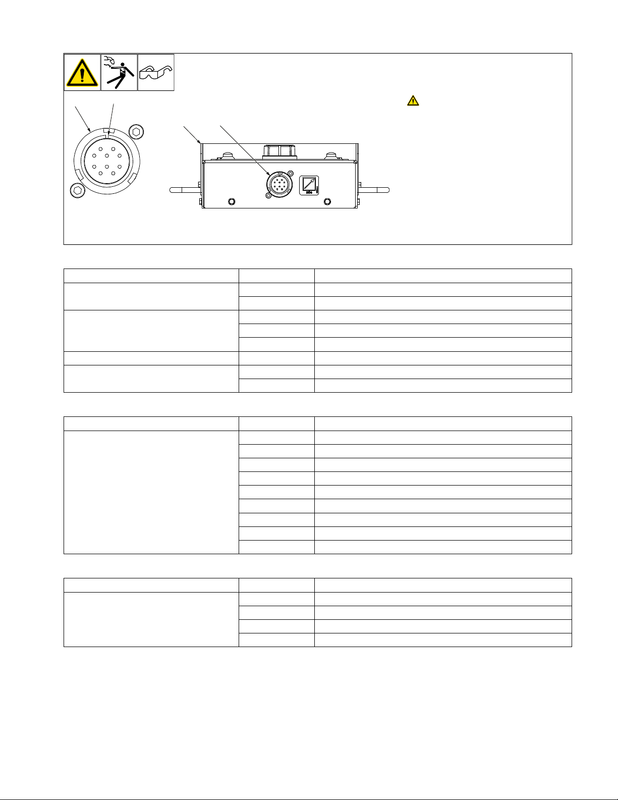
6-2. Bottom Panel Connections For SubArc Remote Pendant Digital
1
2
3 1
277882-A
Turn Off welding power source and
weld control before making
connections.
1 Receptacle RC4
Connection To Motor Control Digital
2 Keyway
3 SubArc Remote Pendant Digital (Bottom
View)
6-3. Remote Receptacle RC1 Information For SubArc Motor Control Digital
Function Circuit Contact Information
Electrical Input Power
Accessory Serial Communication
Shield H Contact J/V shield drain lead
Volt Sense
A, B 24 VAC. Protected by circuit breaker CB2
C, D 24 VAC neutral
J + Accessory RS−485 communication
V − Accessory RS−485 communication
Q Accessory serial communication common
W + Volt sense
X Reserved for − volt sense
6-4. Remote Receptacle RC2 Information For SubArc Motor Control Digital
Function Circuit Contact Information
J Positive (+) motor armature (38 VDC motor)
A Negative (−) motor armature (38 VDC motor)
H Motor identification (resistor across H and B)
C Shield drain leads
Wire feed Drive Motor Hookups
I Encoder VCC (+5 VDC)
K Encoder channel A
B Encoder common and motor identification (resistor across H and B)
E Reserved for negative volt sense
F Positive volt sense
6-5. Remote Receptacle RC3 Information For SubArc Motor Control Digital
Function Circuit Contact Information
A 12 VDC average PWM drive for flux hopper
Flux Hopper Hookups
B Not used
C Circuit common for flux hopper
D Not used
OM-294120 Page 19
Page 25
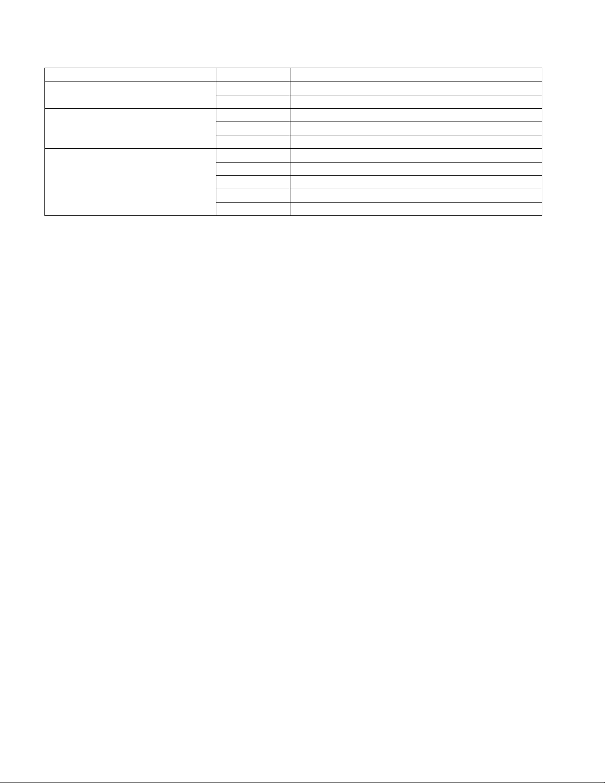
6-6. Remote Receptacle RC4 Information For SubArc Remote Pendant Digital And
Motor Control Digital
Function Circuit Contact Information
Electrical Input Power
Accessory Serial Communication
Push Buttons
B 42 VDC common.
D 42 VDC.
I +Accessory RS-485 communication.
G −Accessory RS-485 communication.
H Chassis.
A Jog up.
C Start.
E Stop.
F COM EXT.
J Jog down.
OM-294120 Page 20
Page 26
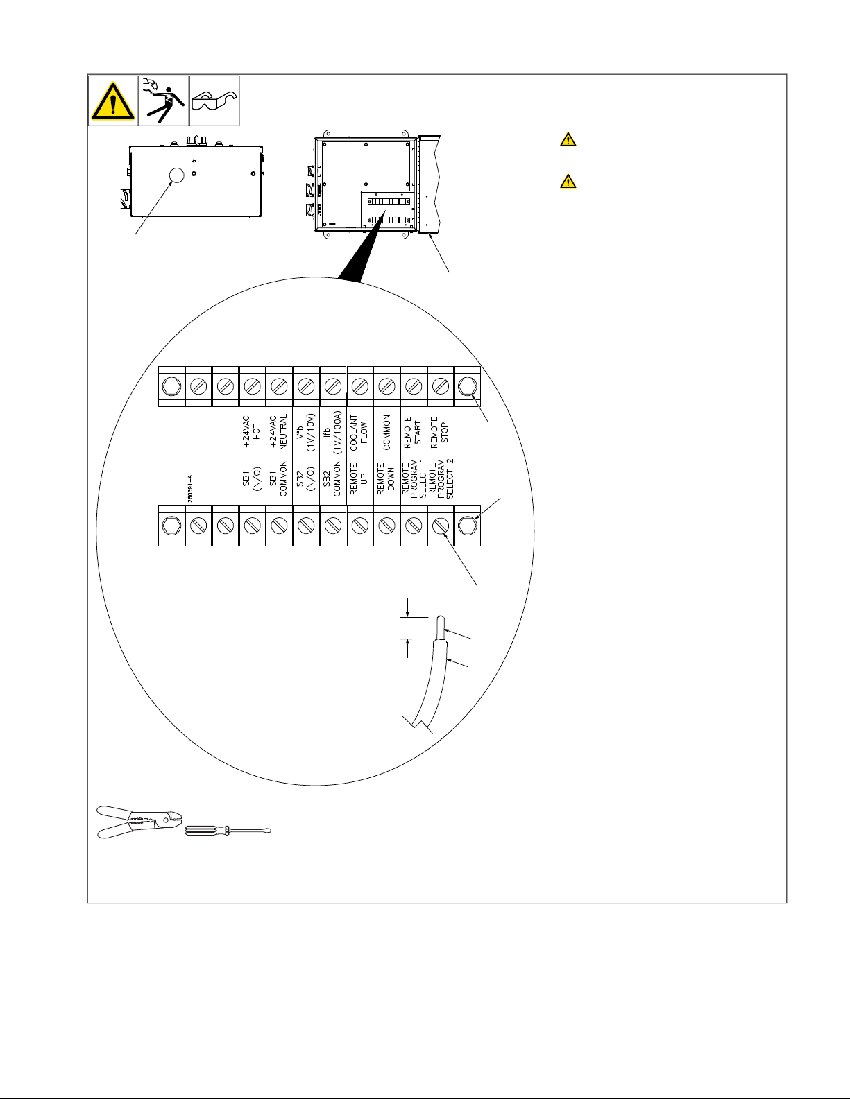
6-7. Terminal Block TB1 And TB2 Connections For SubArc Motor Control Digital
Ref. 265695-A / 267618-A
1
2
3
4
5
6
7
1/4 in
(6 mm)
NGO’s
tools/
flathead philips head wrench
knife
allen_set
needlenose
steelbrush nutdriver
chippinghammer
crescent wrench
NGO’s
tools/
Turn Off welding power source and
weld control before making
connections.
Disconnect input power before
opening access door.
1 Access Door
Remove securing screws and open access
door.
2 Terminal Block TB2
3 Terminal Block TB1
4 Securing Screw - Terminal Block
5 Stripped Lead
6 Typical Lead Being Connected To Termi-
nal Block
7 Access Hole - Used For Connections To
Terminal Blocks, Flux Valve, etc.
Install strain relief (customer supplied)
F
in access hole.
Strip 1/4 in (6 mm) insulation off end of lead,
insert end into proper location on TB1 and
TB2. Tighten applicable securing screw.
Close and secure access door.
OM-294120 Page 21
Page 27

6-8. Terminal Block TB1 Connections For SubArc Motor Control Digital
Terminal Function Information
Blank Not used.
Blank Not used.
SB1
SB1 Common Common used with Relay 1.
SB2
SB2 Common Common used with Relay 2.
Remote UP When connected to Common (on TB2), jogs wire up.
Remote Down When connected to Common (on TB2), jogs wire down.
Remote Program Select 1 See Section 7-13.
Remote Program Select 2 See Section 7-13.
*All contacts are rated 10 amperes, 125 volts AC.
Normally open set of contacts* that defaults close when power source contactor energizes
after the start button is pressed and preflux has timed out. On digital models, this condition
is programmable via auxiliary menus (see Section 7-7).
Normally open set of contacts* that close when an arc is established. These contacts are
used when you want the side beam to start moving once an arc has been established. Contacts open again when the stop button is pressed. On digital models, this condition is programmable via auxiliary menus (see Section 7-7).
6-9. Terminal Block TB2 Connections For SubArc Motor Control Digital
Terminal Function Information
Blank Not used.
Blank Not used.
+24 volts Hot
24 volts AC Neutral
VFB
IFB
Coolant Flow* Connect to coolant flow sensor. Coolant flow is detected when this pin is tied to Common.
Common External common.
Remote Start Starts the weld cycle when connected to Common
Remote Stop Stops the weld cycle when connected to Common
*The Coolant Flow Sensor feature is only active when a Strip Drive 100 is connected to the interface.
24 VAC power supply.
Voltage feedback 1V/10V (Scaled feedback accuracy within ±5% of output. Feedback is for
reference only.)
Current feedback 1A/100A (Scaled feedback accuracy within ±5% of output. Feedback is
for reference only).
OM-294120 Page 22
Page 28
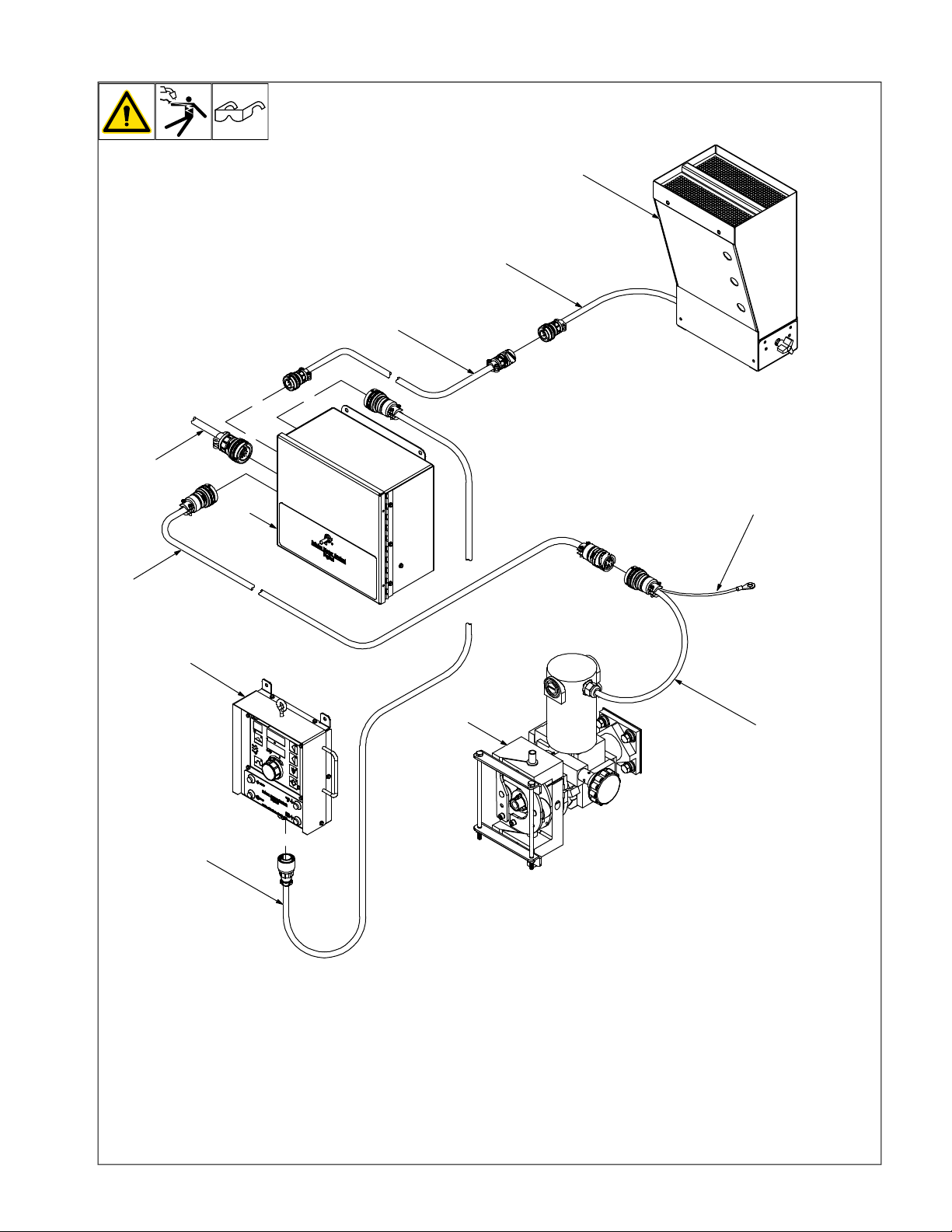
6-10. SubArc Motor Control Digital Plug Connections
4
8
9
6
10
1
2
3
11
7
5
278023-B
Motor shown without feed roller guard.
F
See section 6-10 for receptacle
F
locations.
1 SubArc Motor Control Digital
2 SubArc Remote Control Digital
3 Wire Drive Assembly
4 Flux Hopper
The XXX part no. suffix refers to the cable
length in feet (e.g. 020 suffix is a 20 ft extension cable).
5 Remote Pendant Control Cable - Part
No. 263368XXX (Continuum Control
Cable)
6 Power Source Control Cable Part No.
260622XXX
7 Motor Control Cable
8 Flux Hopper Control Cable
9 Flux Hopper Extension Cable Part No.
260623XXX
10 Motor Extension Cable - Part No.
254232XXX
11 Positive Volt Sense Lead
Connect positive volts sense leads to torch.
OM-294120 Page 23
Page 29
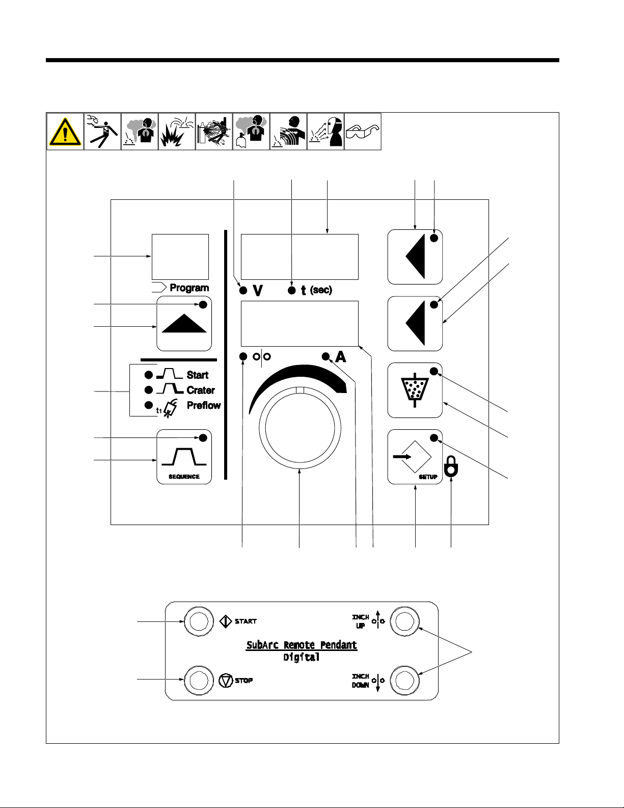
SECTION 7 – OPERATION
236564-B
Ref. 277880-A
25
24
23
51
2 3
4
11
6
7
8
9
10
22
21
20
19
18
12
14
13
17
16
15
7-1. Weld Control Definitions
OM-294120 Page 24
Page 30

When the system interface is turned
F
on, it detects the type of power source
and motor that are being connected.
Power switch is located on the SubArc
F
Motor Control Digital box. Turn switch
ON to energize the control box. Turn
switch OFF to shut down the controller.
1 Adjust Control
The adjust control is used to adjust various
parameters. Refer to the definition for the
function in question for information related to
using the Adjust Control.
2 Upper Display
The upper display shows voltage or time.
The unit displays both preset and actual arc
voltage. When the unit is in a welding state,
actual arc voltage is displayed. The upper
display shows welding sequence time when
the Time LED is illuminated.
3 Upper Display Push Button
Press and hold button to adjust or display
weld time. Release button to display voltage.
4 Upper Display Push Button LED
The upper display push button LED illuminates to indicate that information displayed
can be changed with the Adjust control.
5 Lower Display
The lower display shows wire feed speed or
amperage.
6 Lower Display Push Button
Press button to choose between wire feed
speed or amperage functions.
7 Lower Display Push Button LED
The lower display push button LED illuminates to indicate that information displayed
can be changed with the Adjust control.
8 Volts LED
9 Time LED
10 Wire Feed Speed LED
11 Amps LED
The LEDs below each display illuminate to
indicate.
12 Program Display
The number of the active program is displayed here.
13 Program Push Button
Press the Program push button to activate
the program select feature. To change the
program number, press the Program push
button, or rotate the Adjust control.
14 Program Push Button LED
The LED lights to indicate the Program push
button is active.
For more information on setting se-
F
quence parameters See Section 7-2.
15 Sequence Push Button
The Sequence push button allows the selection of welding sequences. The default sequence is Weld and is active upon power up.
Welding sequences other than Weld must be
set prior to initiating the arc. When the unit
enters a welding state, all sequence display
modes are terminated and the weld display
mode is activated.
16 Sequence Push Button LED
In the Weld sequence display mode, the sequence push button LED is off. When the
Sequence push button is pressed, the LED
flashes and continues to flash with subsequent button presses. The LED stops flashing and is off when the unit returns to the
Weld sequence display mode.
17 Welding Sequence LEDs
Three welding sequence LEDs are located
above the Sequence push button: Start, Crater, and Preflow/Postflow. The applicable
LED illuminates to indicate the active welding sequence. The applicable LED will flash
when changing the parameter.
18 Flux Push Button
Press the flux push button to open or close
the flux valve.
19 Flux Push Button LED
When the Flux push button LED is lit, the flux
valve control is open.
See Section 7-4 for more information on Setup Screens.
20 Setup Push Button
Press the Setup push button to active the
setup display mode. Subsequent button
presses toggle through the setup screens.
21 Setup Push Button LED
The setup push button LED illuminates when
the setup display mode is active.
22 Lock LED
The Lock LED illuminates when locks are
active.
23 Stop Switch
Ends weld process.
24 Start Switch
Starts weld process.
25 Inch Up/Inch Down Push Buttons
These Inch or Jog switches are momentary
push button switches, which energize only
the drive motor, allowing for a cold wire jog.
The welding wire jogs at the rate set by the
Jog Speed control. To advance the wire out
of the torch, press the Inch Down switch. To
retract the wire into the torch, press the Inch
Up switch.
l To set a sequence time, press the upper
display push button repeatedly until time
[t] is the active parameter. Use Adjust
control to set desired time. To disable,
set time to zero.
l The unit defaults to displaying welding
voltage when a welding sequence display mode is first entered.
For CV Mode Only:
l At any time during welding, the Adjust
control can be used to change the weld
wire feed speed when the lower display
push button LED is illuminated. Wire
feed speed will show on the lower display. After approximately one second of
inactivity, the lower display will revert to
showing the previously viewed
parameter.
For CV+C Mode Only:
l At any time during welding, the Adjust
control can be used to change the weld
amperage when the lower display push
button LED is illuminated. Weld amperage will show in the lower display. After
approximately one second of inactivity,
the lower display will revert to showing
the previously displayed parameter.
General Terms: The following is a list of terms and their definitions as they apply to this product.
Sequence - A portion of the weld program, such as preflow, run-in, start, weld, crater, burnback, and postflow.
Weld Program - A group of sequences that make up a weld cycle.
OM-294120 Page 25
Page 31
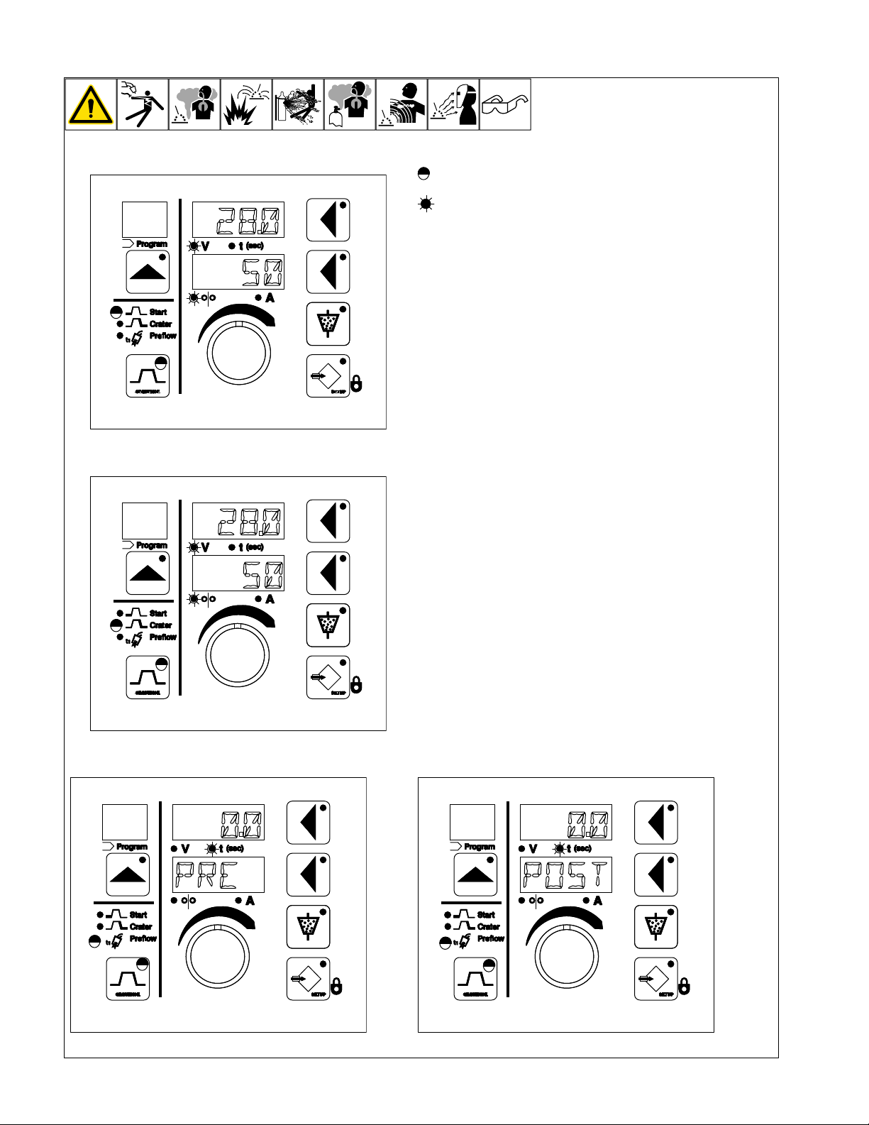
7-2. Weld Sequence Displays
50
280.
50
280
.
00
PRE
.
POST
00
.
Start:
Crater:
= LED Flashing
= LED On
CV mode − Start and Crater display wire feed speed in lower display.
CV+C mode − Start and Crater display amps in lower display.
For all modes − When upper display push button LED is lit, use Adjust
control to change corresponding display value. If the upper display
push button LED is not lit and adjustments are desired, press the Upper
Display push button to turn on the LED. Pressing the button again will
toggle between voltage and time. The Volts or Time LED will illuminate
to indicate which value is being displayed.
If the lower display push button LED is lit, use the Adjust control to
change the value.
l Press Sequence push button, and the sequence push button LED
and Start LEDs flash. In this condition, the unit is in the Start sequence display mode, and Start sequence parameters are shown
in the displays.
l Press Sequence push button a second time, and the sequence
push button LED and the Crater sequence LED flash. In this condition, the unit is in the Crater sequence display mode and the Crater
sequence parameters are shown in the displays.
l Press Sequence push button a third time, and the sequence push
button LED and the Preflow/Postflow sequence LED flash.
l Press the lower display button to select between preflow and
postflow.
l In the Preflow display mode, the upper display shows the preflow
time and PRE is shown in the lower display. To change the preflow
time, press the upper display button and turn the Adjust control.
l In Postflow display mode, the upper display shows the postflow
time and POST is shown in the lower display. To change the postflow time, press the upper display and turn the Adjust control.
PreFlow: PostFlow:
OM-294120 Page 26
Page 32
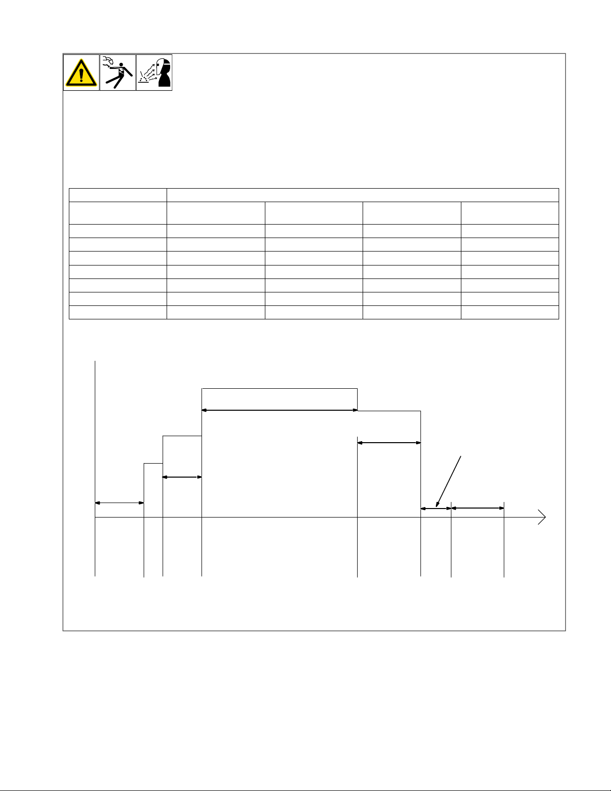
7-3. Weld Sequence Parameters In A Program
Weld Time
Crater Time
Postflow TIme
Time
Start
Time
Preflow
Time
Preflow
Start Button
Run-In Start Weld Crater
Stop Button
Burnback Postflow Sequence End
Burnback Time
For more information on Sequence
F
push buttons, see Section 7-2.
If time is set to zero in Weld Sequence, welding continues until stop button is pressed.
If time is set to zero in any timed sequence
except Weld, the sequence is skipped.
Sequence Parameters
Volts
(CV or CV+C)
1. Preflow 0.0-10.0
2. Run-In X
3. Start X X X 0.00-10.00
4. Weld X X X 0.0-600.0
5. Crater X X X 0.00-10.00
6. Burnback X X X 0.00-10.00
7. Postflow 0.0-10.0
Amps
(CV+C)
Wirespeed
(CV)
Seconds
OM-294120 Page 27
Page 33
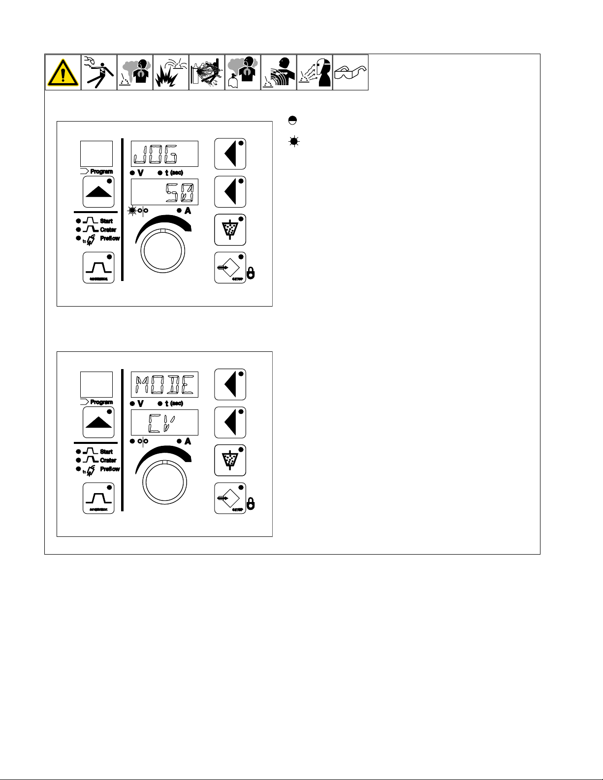
7-4. Setup Screens
JOG
50
MODE
CV
= LED Flashing
= LED On
Press the setup push button to enter the setup screens. If the pa-
F
rameter is program specific, the active program is displayed in the
program display. The active program can be changed by pressing
the Program push button and then selecting the desired program
with the Adjust control.
l Jog
The jog speed selection, indicated by JOG in the upper display, can be
changed by turning the Adjust control. The jog wire feed speed setting
is the same for all programs. The jog wire feed speed may also be adjusted while the Inch Up or Inch Down button are pressed.
l Mode
Welding mode, indicated by MODE in the upper display, is set to CV for
constant voltage or CV+C for constant voltage plus current, indicated in
the lower display. Use the Adjust control to change the mode when the
lower display push button LED is lit. This setting is program specific.
OM-294120 Page 28
Page 34
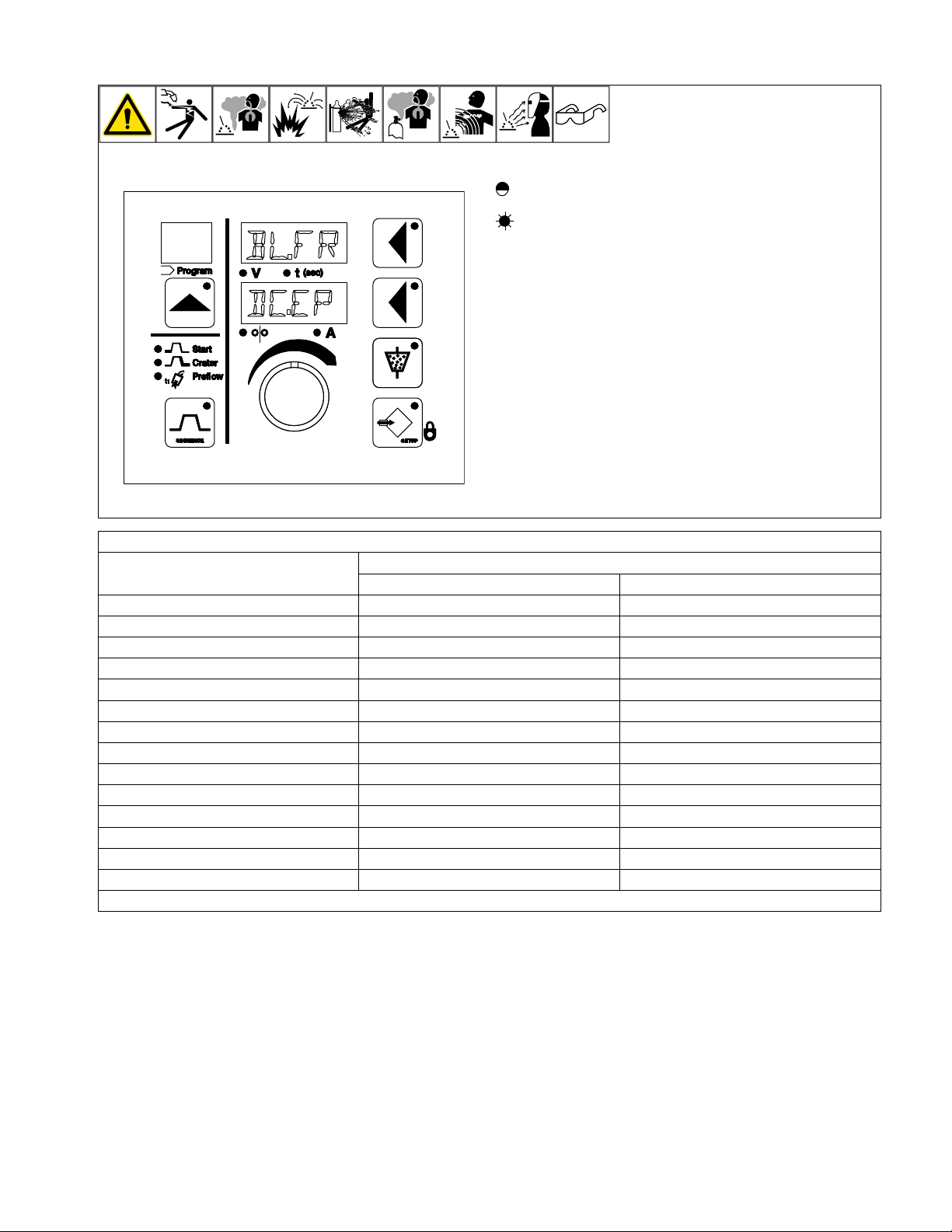
7-5. Setup Screens (Continued)
BLFR
DCEP
.
.
= LED Flashing
= LED On
Press the setup push button to enter the setup screens. If the
F
parameter is program specific, the active program is displayed
in the program display. The active program can be changed by
pressing the Program push button and then selecting the desired program with the Adjust control.
l Balance (AC Units Only)
Balance selection, indicated by BL. FR in the upper display, adjusts
the AC balance and frequency, shown on the lower display. The first
two digits indicate the positive balance value followed by a decimal
point. The two digits after the decimal point indicate frequency. The
balance and frequency are dependent on one another, and cannot be
individually adjusted. Use the Adjust control to change this parameter
when the lower display push button LED is lit. This setting is program
specific (see Table 7-1 for a list of available balances and frequency).
Balance
%Positive / %Negative
100/0 DC.EP DC.EP
80/20 80.18 80.15
75/25 75.23 75.19
70/30 70.18 70.15
67/33 67.30 67.25
60/40 60.18 60.15
50/50 50.30 50.25
50/50 50.18 50.15
40/60 40.18 40.15
33/67 33.30 33.25
30/70 30.18 30.15
25/75 25.23 25.19
20/80 20.18 20.15
0/100 DC.EN DC.EN
Table 7-1. Balance/Frequency
Display
60 Hz Line Input (US) 50 Hz Line Input (EU)
OM-294120 Page 29
Page 35
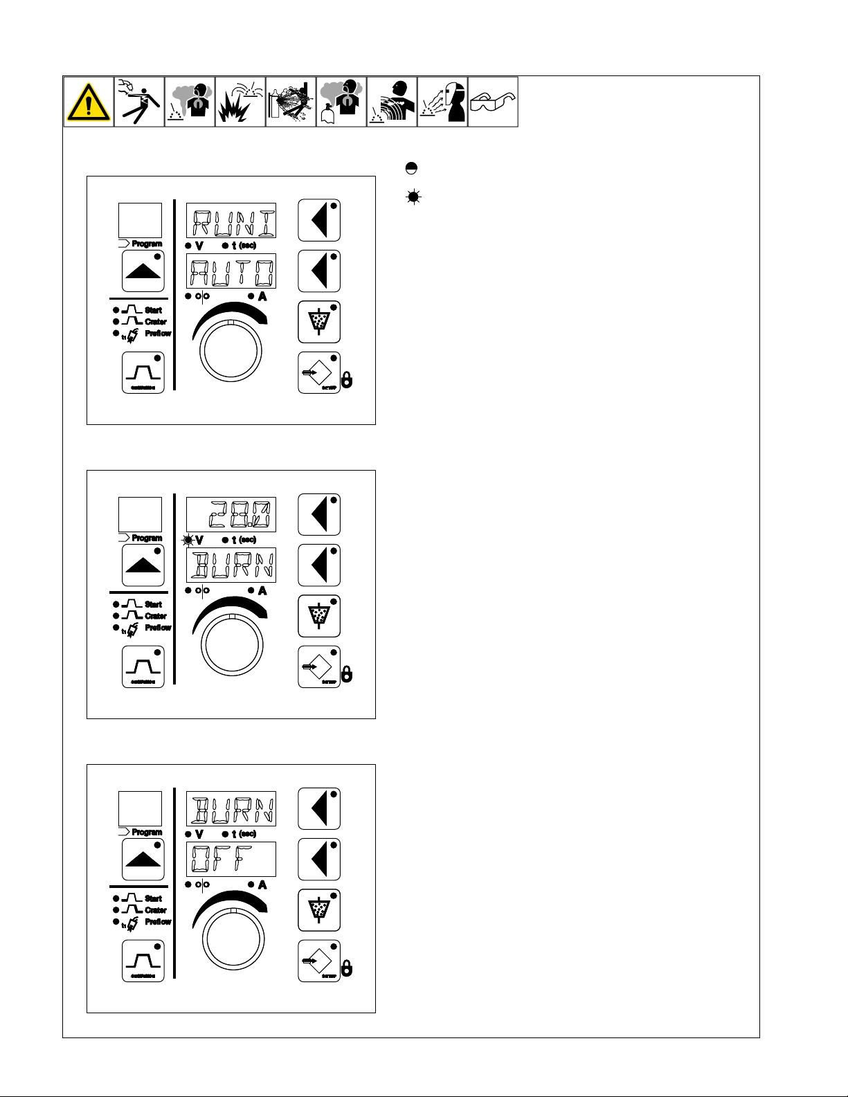
7-6. Setup Screens (Continued)
RUNI
AUTO
280
BURN
.
OFF
BURN
= LED Flashing
= LED On
Press the setup push button to enter the setup screens. If the pa-
F
rameter is program specific, the active program is displayed in the
program display. The active program can be changed by pressing
the Program push button and then selecting the desired program
with the Adjust control.
l Run-In
The run-in selection, indicated by RUNI in the upper display, is set to automatic, off, or manual run-in wire speed. The lower display shows AUTO to indicate that automatic run-in is active. The Adjust control can be
used to change the setting from AUTO to a run-in speed setting. If a
start condition is set, run-in is a percentage of the start wire speed. Otherwise, run-in is a percentage of the weld wire speed. This setting is program specific.
l Burnback
Burnback voltage and time are specified when the lower display shows
BURN and the upper display shows voltage or time. The Adjust control
is used to set the desired burnback voltage or time.
Burnback retract wire speed is specified when the upper display shows
BURN and the lower display shows the setting. Burnback may be set to
OFF with the lower display push button or changed with the Adjust
control.
These settings are program specific.
OM-294120 Page 30
Page 36
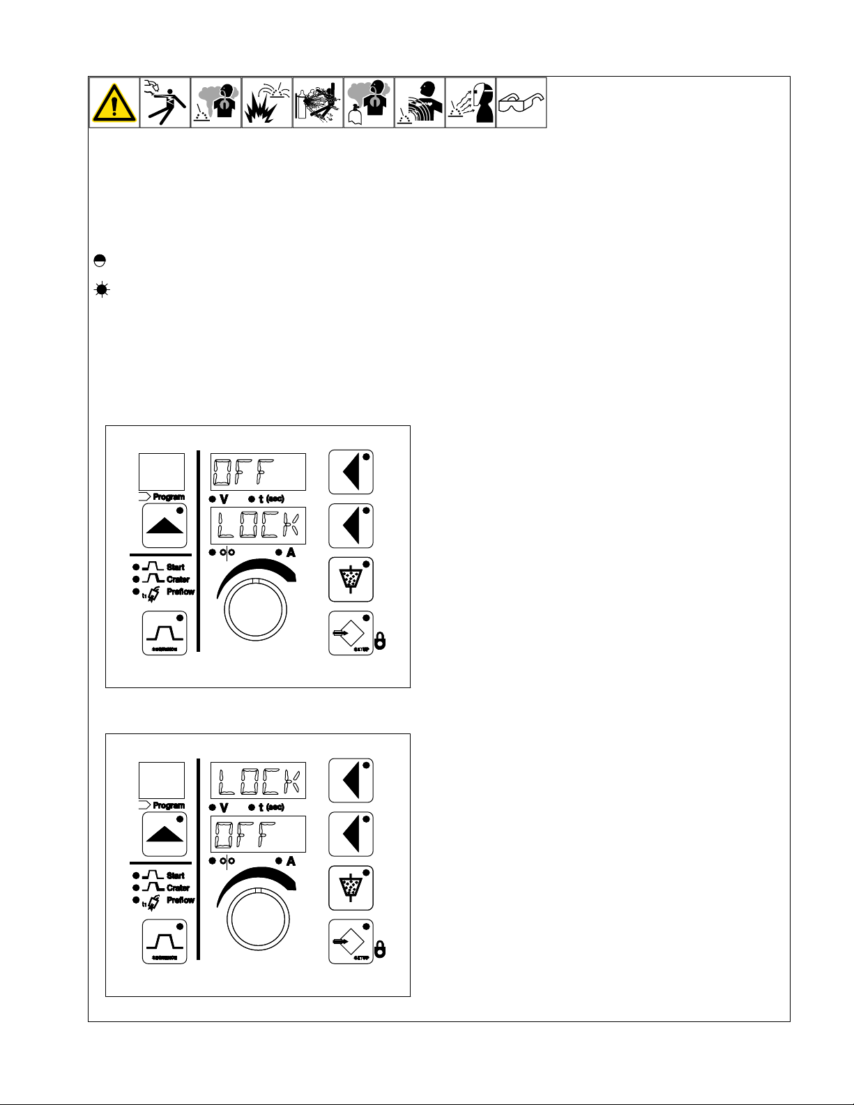
7-7. Auxiliary Menus Screens
OFF
LOCK
LOCK
OFF
An auxiliary menu is provided when both the Sequence and Setup buttons are pressed simultaneously. The Setup and Sequence button LEDs
flash when in the auxiliary menu. Press the Setup button to scroll forward or press the Sequence button to scroll backwards through the auxiliary menu.
To exit auxiliary menu, press Sequence and Setup simultaneously or press inch up or inch down button.
F
= LED Flashing
= LED On
Locks
If locks are active, only locked programs are accessible and the lock LED will be on. To quickly disable the locks for all programs, press
F
the upper and lower display push buttons at the same time.
All locks are program dependent and independent of each other. A different value can be set for each lock for each program.
F
l Voltage Range Lock
Voltage range lock is active when LOCK is shown in the lower display
and the Volts LED is lit. The voltage range lock is off by default and is
confirmed by OFF being shown in the upper display. To set a voltage
variance between 0 to 10 volts from preset voltage, press the upper display button and rotate the adjust control to the desired voltage. The voltage range lock is program dependent and independent from the wire
feed speed and amperage locks. A different voltage variance may be
set for each program.
l Amperage Range Lock (For CV+C Mode Only)
The amperage range lock is indicated by LOCK in the upper display.
The amperage range lock is off by default and OFF is shown in the lower display. To set an amperage variance of 0 to 250 amperes from the
preset amperage, press the lower display button to illuminate the lower
display button LED then turn the Adjust control until the desired amperage variance is set. The Amps LED will illuminate once the parameter is
changed from off to a value.
OM-294120 Page 31
l Wire Feed Speed Range Lock (For CV Mode Only)
The wire feed speed range lock is indicated by LOCK in the upper display. The wire feed speed range lock is off by default and OFF is shown
in the lower display. To set a wire feed speed variance between 0 to 250
ipm (0 to 6.3 mpm) from the preset wire feed speed, press the lower display button to illuminate the lower display button LED then turn the adjust control until the desired wire feed speed variance is set. The Wire
Speed LED will illuminate once the parameter is changed from off to a
value.
Page 37
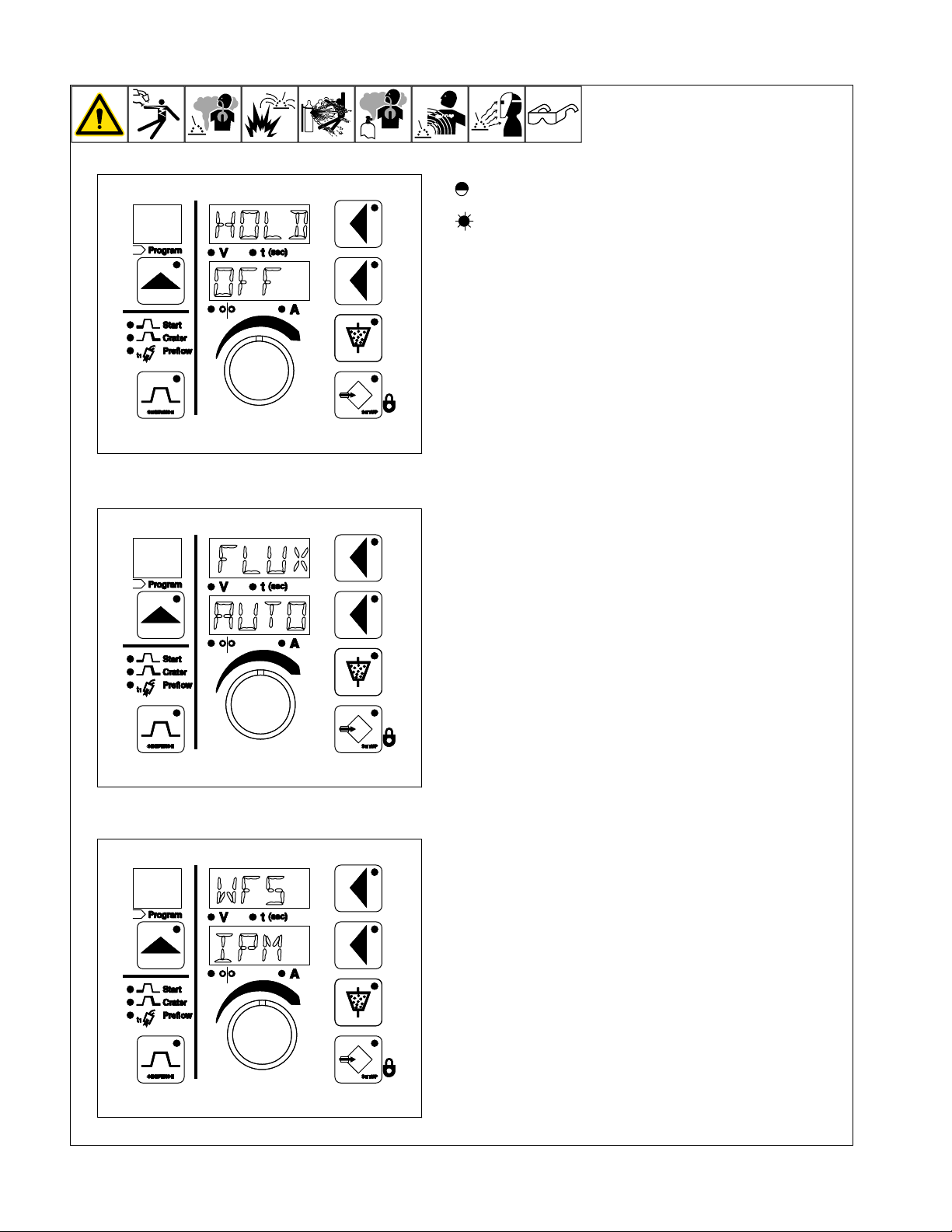
7-8. Auxiliary Menus Screens (Continued)
HOLD
OFF
FLUX
AUTO
WFS
IPM
= LED Flashing
= LED On
l Lock Hold
Lock Hold is indicated by HOLD in the upper display. Lock Hold is set to
off by default and OFF is shown in the lower display. If Lock Hold is desired, press the lower display push button to illuminate the lower display
push button LED then rotate the adjust control to change the setting to
ON.
The Lock Hold feature only works when locks are active and provides
the user with the ability to adjust voltage, amperage, or wire feed speed
within set limits while welding. When welding stops, voltage, amperage,
or wire feed speed adjusted while welding reverts back to the values
preset prior to the weld start. If the Lock Hold feature is turned off, adjustments made to the preset values while welding become the new preset values when welding stops.
l Flux Valve Control
Flux valve control, indicated by FLUX in the upper display, is set to AUTO for automatic control or MAN for manual control. Setting the Flux
valve control to AUTO energizes the flux hopper when the Start button
is pressed and de-energizes the flux hopper when the last sequence is
finished. The flux valve control can be overridden by using the flux button. Setting the flux valve control to MAN requires the user to close and
open the flux valve relay with the flux button.
l Wire Feed Speed Setting
Wire feed speed setting, indicated by WFS in the upper display, can be
set to IPM (inches per minute) or MPM (meters per minute). This setting
is independent of the program selected.
In the Tractor Interface Digital the wire feed speed setting changes the
tractor travel speed units.
OM-294120 Page 32
Page 38
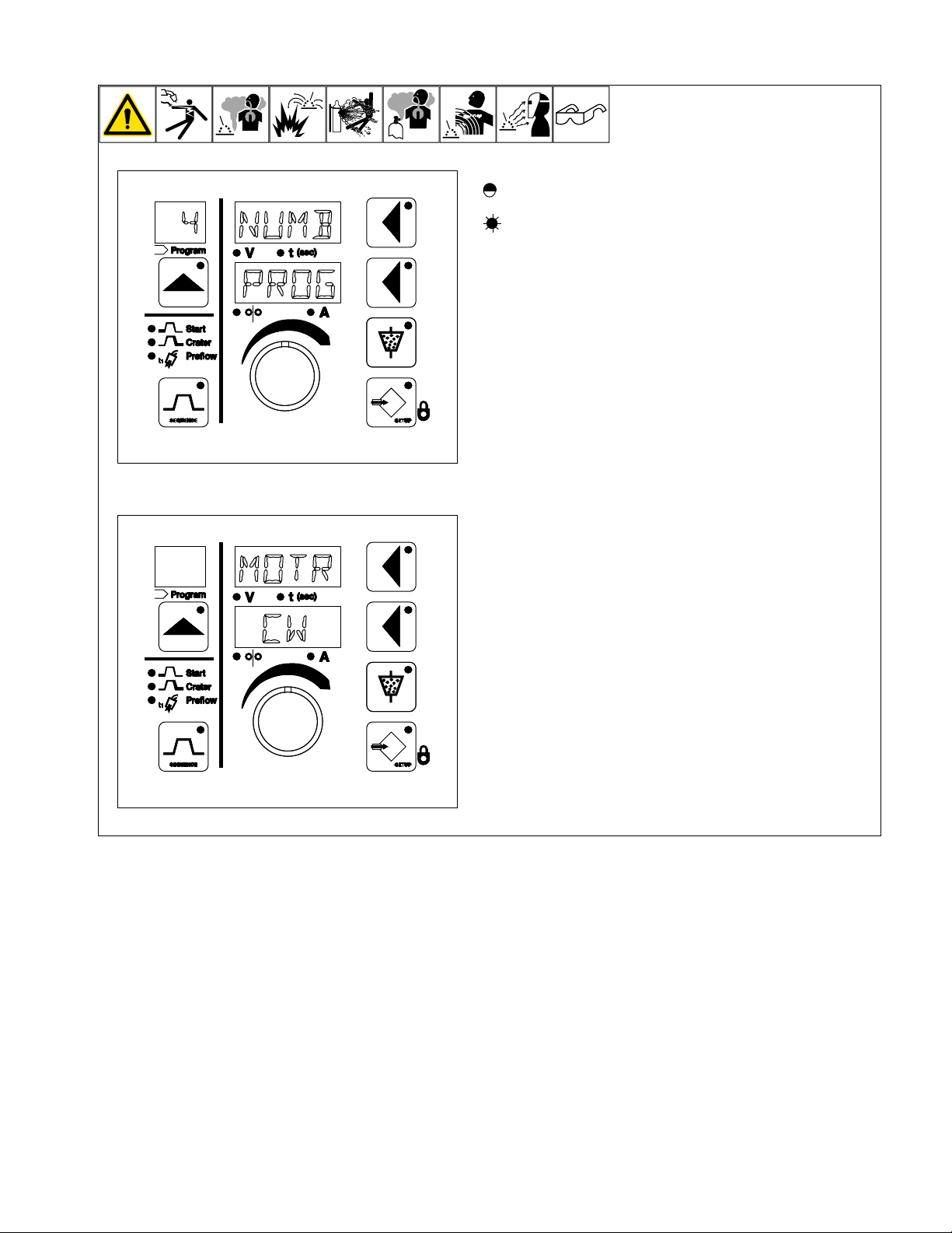
7-9. Auxiliary Menus Screens (Continued)
NUMB
PROG
4
MOTR
CW
= LED Flashing
= LED On
l Number of Programs
The number of programs is indicated by NUMB in the upper display and
PROG in the lower display. The number of user allowed programs (1
through 15) is shown in the program display. Use the adjust control to
change the maximum number of programs that can be accessed.
l Wire Drive Motor Rotation
The motor rotation is indicated by MOTR in the upper display and CW
or CCW in the lower display. Changing between CW and CCW changes
the rotation of the motor.
OM-294120 Page 33
Page 39
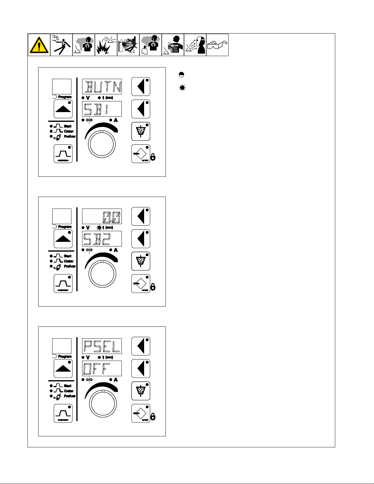
7-10. Auxiliary Menus Screens (Continued)
BUTN
SB1
00
SB2
.
PSEL
OFF
= LED Flashing
= LED On
l Motion Control
Motion control is indicated by SB1 or SB2 in the lower display and is
used to set when the side beam relay engages. When “BUTN” is shown
in the upper display, the side beam relay will engage when the start button is pressed and preflux has timed out. When a positive time is selected, the side beam relay will engage when the selected time has
elapsed after an arc is established. When a negative time is selected,
the side beam relay will engage when the start button is pressed, but
the weld sequence will not start until the selected time has elapsed.
SB1 - For SubArc Tractor Interface Digital - Controls the tractor start of
motion.
l Remote Program Select
Remote program select is indicated by PSEL in the upper display. Use
adjust control to select ON or OFF. (See section 7-13 Remote Program
Select for more information.)
OM-294120 Page 34
Page 40
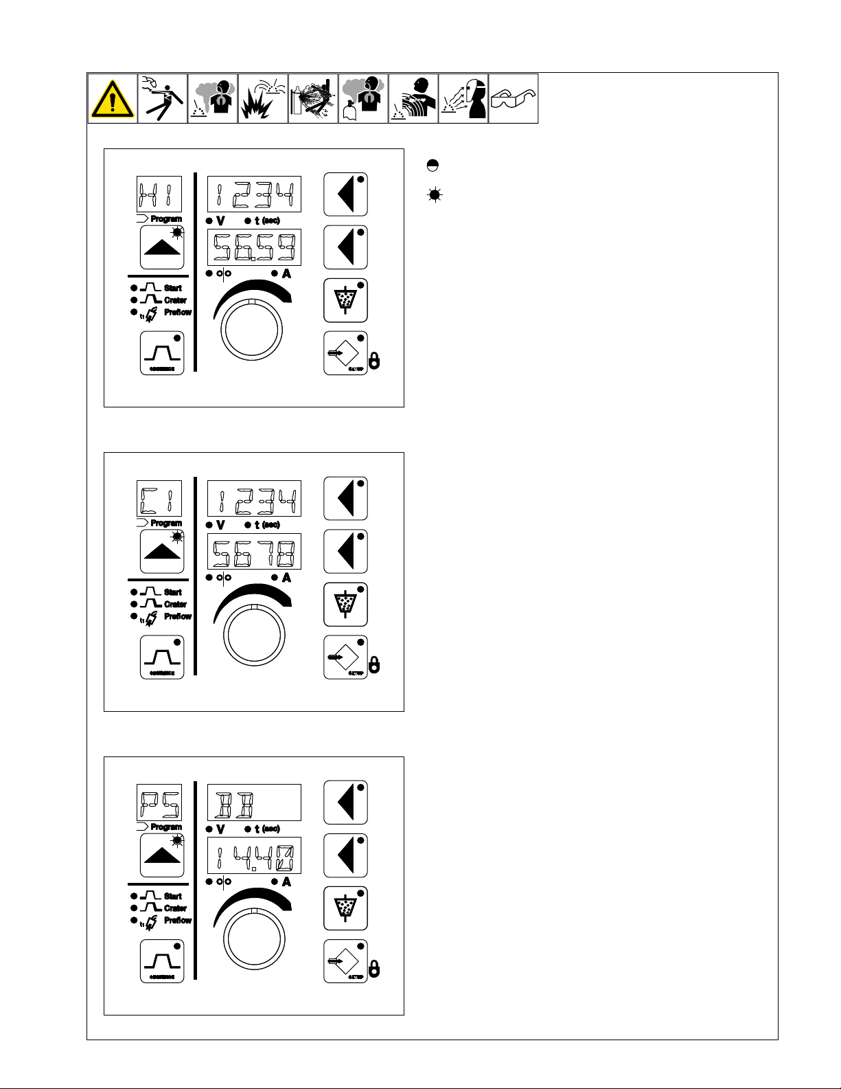
7-11. Auxiliary Menus Screens (Continued)
1234
5659
H1
.
1234
5678
C1
BB
1440
Ps
.
= LED Flashing
= LED On
l Arc Time
When H1 is shown in the program display, the total number of arc hours
is shown in the lower display, wrapping to the upper display. The total
number of arc hours cannot be reset. When H2 is shown in the program
display, the resettable number of arc hours is shown in the lower display,
wrapping to the upper display. The resettable number of arc hours is reset by pressing both the upper and lower display buttons at the same
time. The number following the decimal point in the lower display shows
the number of minutes. Switch between H1 and H2 by using the Adjust
control.
l Cycles
When C1 is shown in the program display, the total number of arc cycles
is shown in the lower display, wrapping to the upper display. The total
number of cycles cannot be reset. When “C2” is shown in the program
display, the resettable number of arc cycles is shown in the lower display, wrapping to the upper display. The resettable number of arc cycles
is reset by pressing both the upper and lower display buttons at the
same time. Switch between C1 and C2 by using the Adjust control.
l Power Source Selection
(14-Pin To SubArc Digital Converter Only)
(see 14-Pin To SubArc Digital Converter owner’s manual).
F
When PS is shown in the program selection window, you can cycle
through the list of compatible power sources by rotating the turn knob.
The format for compatible power sources is either listed in a product/
model format, such as DIM/650 (Dimension 650) OR as a product/
voltage range format such as BB/14.40 (Big Blue 14 to 40 volts). Only
the Big Blue product line follows the product/voltage range format.
OM-294120 Page 35
Page 41
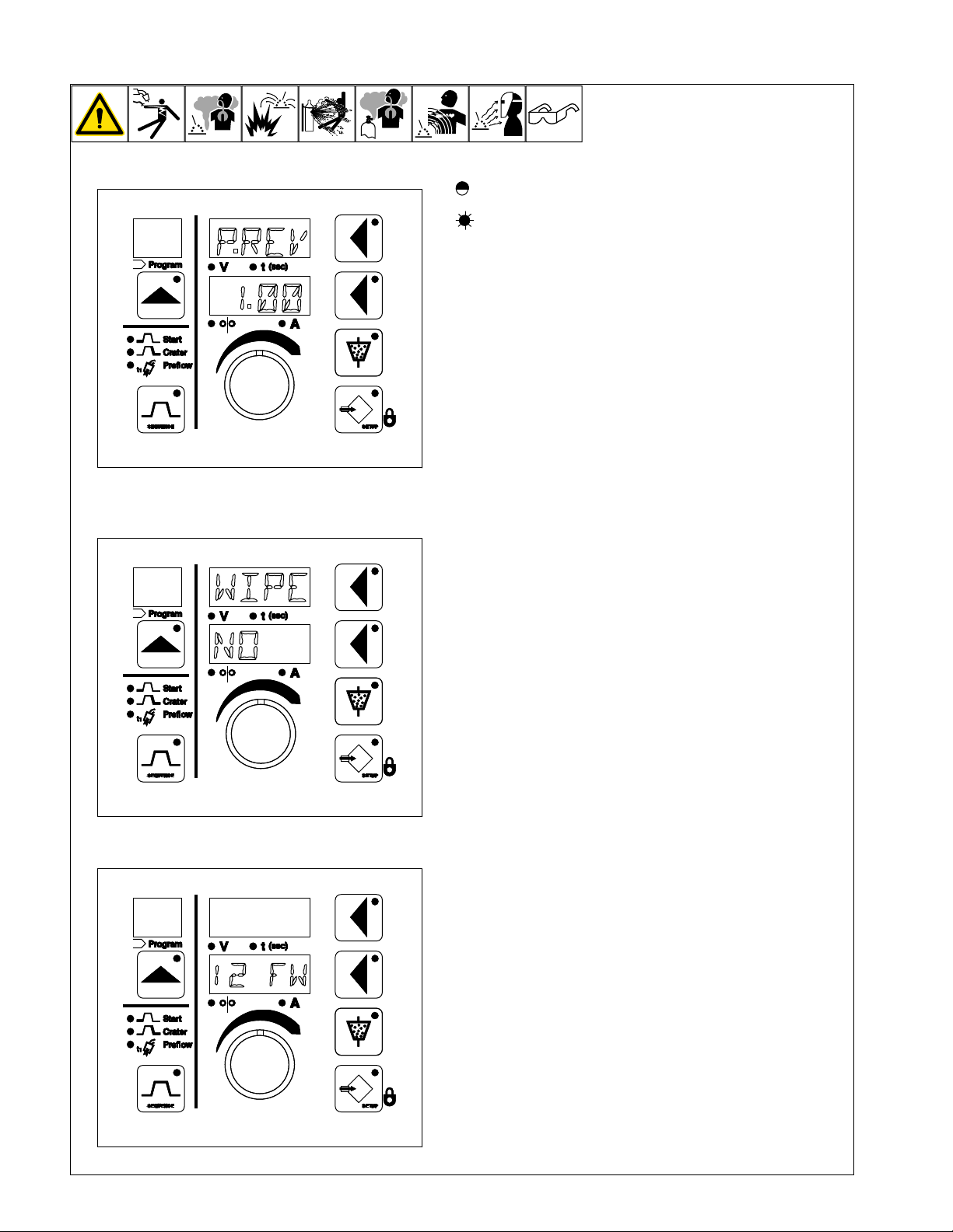
7-12. Auxiliary Menus Screens (Continued)
PREV
100
.
.
WIPE
NO
12 FW
= LED Flashing
= LED On
l Software Revision Level
When P.REV is shown in the upper display, the process control board
revision level is shown in the lower display.
When C.REV is shown in the upper display, the conversion box control
board revision level is shown in the lower display.
When D.REV is shown in the upper display, the display board or tractor
board revision level is shown in the lower display.
When M.REV is shown in the upper display, the motor control board revision level is shown in the lower display.
When A. REV revision is shown in the upper display, the automation
board revision level is shown in the lower display.
Switch between board revisions by using the Adjust control.
l Reset To Factory Settings
To access the reset menu and reset to factory default settings, proceed
as follows: simultaneously press the Program, Sequence, Upper Display, and Setup buttons. WIPE is displayed on the upper display and
NO is displayed on the lower display. The lower display button LED is also lit. Turn adjust control or push lower display button to change lower
display from NO to YES. Simultaneously press the Program, Sequence,
Upper Display, and Setup buttons again. All parameters except the arc
time and cycle count are now reset to factory default settings.
If a reset is not desired, turn the adjust control until the lower display
shows NO and simultaneously press the Program, Sequence, Upper
Display, and Setup buttons.
l Preflow/Side Beam/Wire Feed Timeout
When the Start button is pressed to initiate a weld, the lower display displays up to four specific characters.
1 − Indicates SB1 has been energized
2 − Indicates SB2 has been energized
F − Indicates the flux valve has been activated
W − Indicates that the motor has begun to feed wire (Run In)
The characters will display at different times, depending on if there is a
preflow time set or if there is a negative time set in the SB menu.
The top display will count down from the longest preset time, or will display all zeros (0.0).
OM-294120 Page 36
Page 42
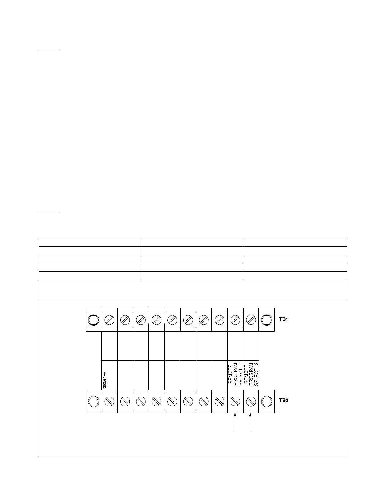
7-13. Remote Program Select For SubArc Motor Control Digital
TB1
TB2
Ref. 267618-A
There are two methods to remotely change programs.
F
Method 1
Remote Program Select 1
In the auxiliary menu, turn Remote Program Select Off (see Section 7-10, Remote Program Select).
Connecting Terminal Block TB1 Remote Program Select 1 (see Section 6-8) to Terminal Block TB2 Common (see Section 6-9) will increment
the program. Once the last program is reached, connecting Terminal Block TB1 Remote Program to Terminal Block TB1 Remote Common will
change the program to the first program.
Example - If the number of programs is set to 4 (see Section 7-9, Number Of Programs) and locks are disabled, then repeatedly connecting and
disconnecting Terminal Block TB1 Remote Program Select 1 to Terminal Block TB2 Common will change the programs in the following way:
Program1 −>Program 2 −>Program 3 −>Program 4 −> Program1
Remote Program Select 2
In the auxiliary menu, turn Remote Program select Off (see Section 7-10, Remote Program Select).
Connecting Terminal Block TB1 Remote Program Select 2 (see Section 6-8) to Terminal Block TB2 Common (see Section 6-9) will decrement
the program. Once the first program is reached, connecting Terminal block TB1 Remote Program Select 2 to Terminal Block TB2 Common will
change the program to the last program.
Example − If the number of programs is set to 4 (see Section 7-9, Number Of Programs) and locks are disabled, then repeatedly connecting and
disconnecting Terminal Block TB1 Remote Program Select 2 to Terminal Block TB2 Common will change the programs in the following way:
Program 4> Program 3> Program 2> Program 1> Program 4.
If locks are enabled, (see Section 7-7, Locks) Voltage Range Lock or Amperage Range Lock or Wire Feed Speed Range Lock) then the program
will be incremented to the next locked program.
Method 2
In the auxiliary menu, turn remote program select on (see Section 7-10, Remote Program Select). Then one of 4 programs can be selected by
connecting to the Remote Program Select Pins to common as shown in the following table.
Program Selected Remote Program Select 1 Remote Program Select 2
Program 1 Not Connected Not Connected
Program 2 Connected Not Connected
Program 3 Not Connected Connected
Program 4 Connected Connected
If locks are enabled (see Section 7-7 Locks) and an unlocked program is selected, a program select error is displayed until a locked pro-
F
gram is selected or the remote program select feature is turned off. If method two is used, method 2 will automatically disable method 1.
OM-294120 Page 37
Terminal Strip
Page 43
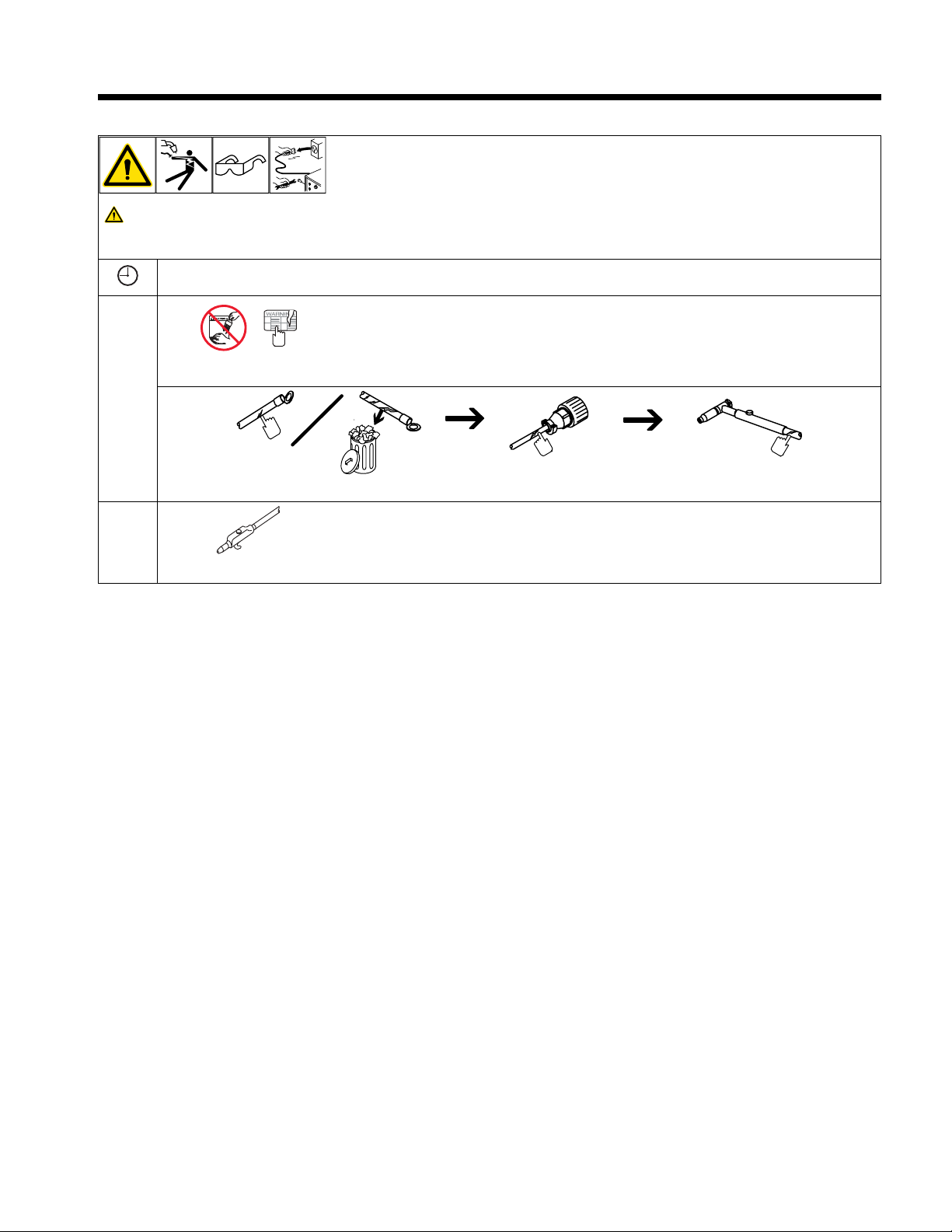
Complete Parts List is available at www.MillerWelds.com
NGO’s
tools/
flathead philips head wrench
knife
heavy-duty workclamp light-duty workclamp wirecutter frontcutter
allen_set
steelbrush nutdriver
chippi
nghammer
imp
d
rill
greasegun
handream
f
ilterwrench
crescent wrench
F
SECTION 8 – MAINTENANCE AND TROUBLESHOOTING
8-1. Routine Maintenance
Disconnect power before maintaining.
Maintain more often during severe conditions.
F
ü = Check ◇ = Change m = Clean ¶ = Replace
Every 3
Months
ü ¶ Labels
ü ¶ Cables And Cords
Every 6
Months
m During heavy service, clean monthly.
OM-294120 Page 38
Page 44
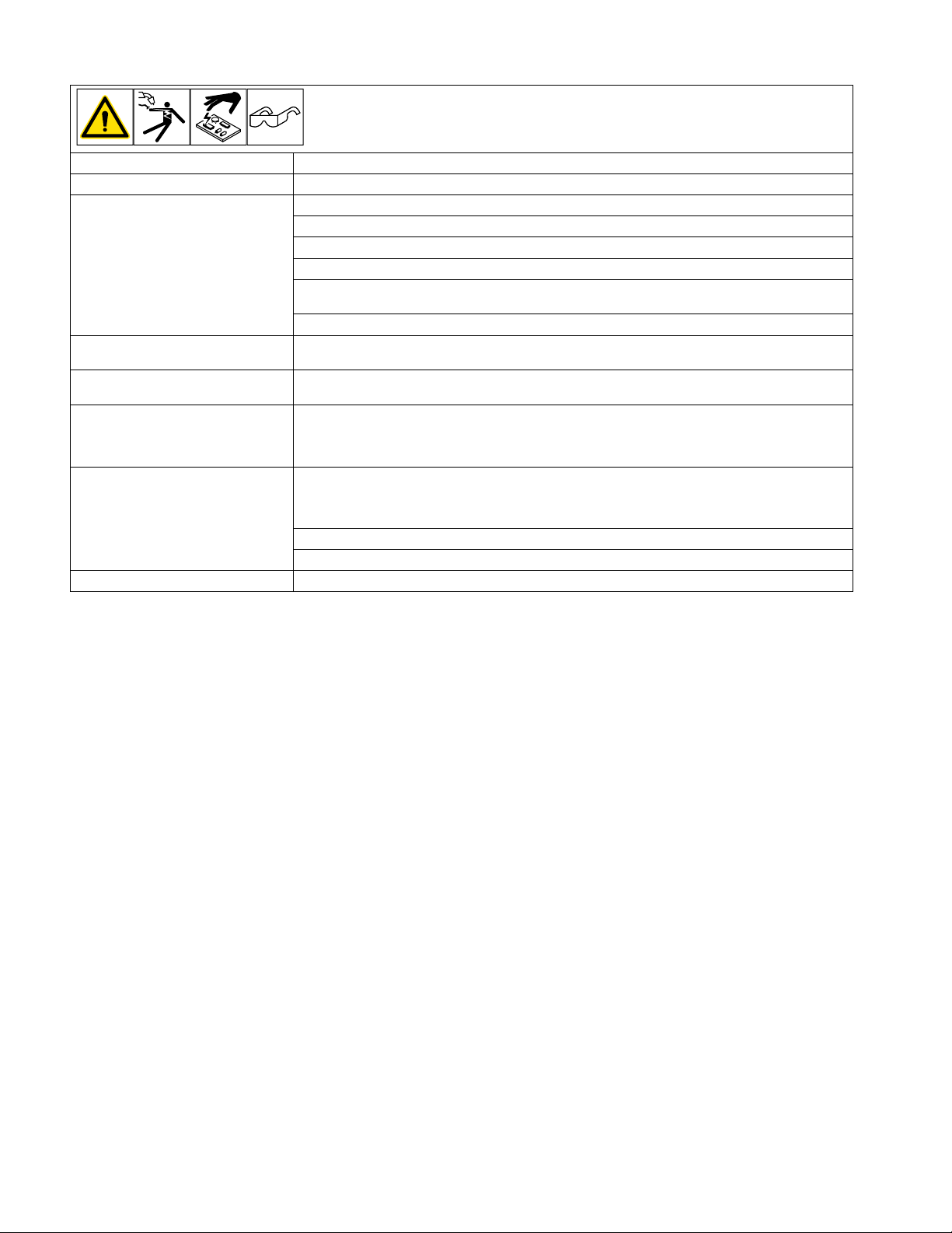
Complete Parts List is available at www.MillerWelds.com
F
8-2. Troubleshooting Table
Trouble Remedy
Unit is completely inoperative. Check 24 VAC input power and be sure it is energized.
Wire does not feed during jogging. Place Power Switch S1 in On position.
Check 24 volts AC input power and be sure it is energized.
Jog Speed Control set too low; increase Jog Speed setting (see Section 7-4).
Check wire feed motor, and repair or replace if necessary.
Check Inch Up push buttons PB3 and Inch Down push button PB4, and replace if necessary
(see Parts Manual).
Have Factory Authorized Service Agent check control board PC1, and replace if necessary.
Wire feeds wrong direction during
jogging.
Wire only feeds down whether Inch
Down or Up button is pressed.
Wire does not feed after Start button is
pressed (ensure that all wire feed jogging functions are operating properly
before checking this problem).
No wire feed speed control with Wire
Speed control during welding. Wire
speed remains at the Run−In Wire
Speed setting.
Erratic weld and no control of output. Check remote voltage sense lead polarity.
Change wire drive motor rotation setting in the Auxiliary Menu (see Section 7-9).
Have Factory Authorized Service Agent check control board PC1, and replace if necessary.
Check Start switch PB1, and replace if necessary.
Wire feed speed cannot be directly controlled in CV+C mode.
Verify volt sense leads are properly connected.
Have Factory Authorized Service Agent check control board PC1, and replace if necessary.
OM-294120 Page 39
Page 45
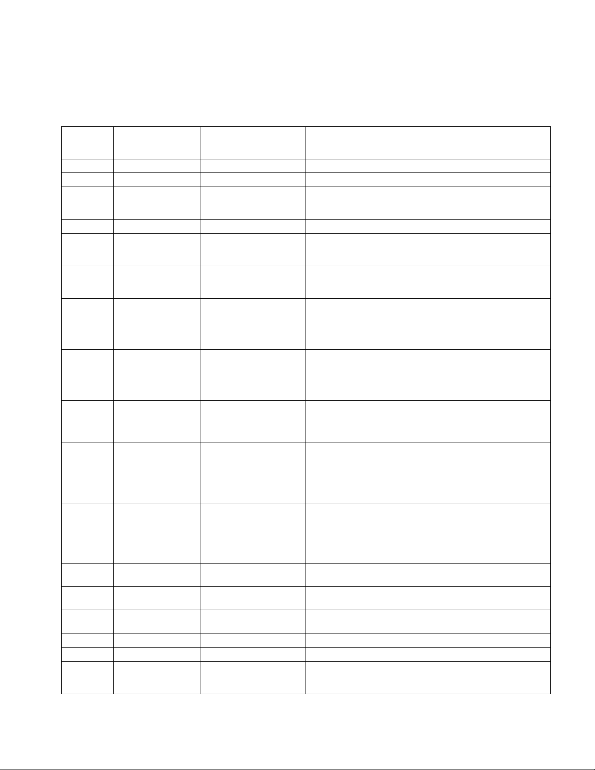
Complete Parts List is available at www.MillerWelds.com
F
8-3. Help Codes
A. SubArc System
HELP will display in the upper display, and the code number will display in the lower display.
F
Each flash sequence will be followed by a one second pause. The sequence will then repeat.
F
SubArc
Help Code
03 3 Slow (flashes) See 30
04 4 Slow See 40
05 5 Slow
06 6 Slow See 60
26 2 Quick, 6 Slow
30 3 Quick
32 3 Quick, 2 Slow Coolant Flow Error
40 4 Quick Tach Error
42 4 Quick, 2 Slow Motor Error
44 4 Quick, 4 Slow Motor Low Bus
45 4 Quick, 5 Slow
48 4 Quick, 8 Slow Trigger Fault
56 5 Quick, 6 Slow Modbus Control Fault
60 6 Quick Memory Card Fault
61 6 Quick, 1 Slow File Read Error Indicates faulty file on memory card.
62 6 Quick, 2 Slow File Write Error Indicates full or faulty memory card.
63 6 Quick, 3 Slow Invalid File
SubArc Power
Source
Status/Trouble Light
Fault Description
Primary Circuit Over
Temperature
Button Stuck On System In-
terface Motor Control
Stuck Contactor On Power
Source
Button Stuck On Display Or
Tractor Error
Indicates unit has overheated. Unit has shutdown to allow fans to lower temperature. Operation will continue after unit is within normal temperature range.
Indicates button is stuck on the lower half of the SubArc interface
upon start up, or Remote Start, Jog Up, or Jog Down is being held
low during start up. Fault will clear when button is released.
Indicates stuck contactor on (Output On switch) the power source.
Fault will clear when panel switch is set to remote or contactor is
released.
Indicates coolant input on TB2 in the SubArc Interface is not connected to common on TB2 (see appropriate Interface OM).
Check coolant flow and common connections.
Ensure sensor being used has a normally-open contact. Sensor is only active if a Strip Drive 100 is connected.
Indicates tach error on motor. Check wire feed drive housing and wire
spool for obstructions. Make sure motor cable is not routed with weld
cable (If inching works properly, noise may be corrupting the tach signal). If this code continues to appear on the display, contact the nearest Factory Authorized Service Agent.
Indicates motor overcurrent error on motor. Check wire feed drive
housing and wire spool for obstructions. If this code continues to appear on the display, contact the nearest Factory Authorized Service
Agent.
Indicates bus voltage in SubArc Interface is low. 24 VAC from power
source may be low if input primary line voltage is too low or, for DC
power sources, power source could be incorrectly linked. Increase
primary line voltage to at least 90% of specified nominal voltage.
Check for correct linking on DC power sources. If this code continues
to appear, contact nearest Factory Authorized Service Agent.
Indicates button is stuck on the digital interface upon power up. Fault
will clear when button is released.
OR
A tractor error is present. The Tractor Speed Display will contain an
additional help code indication. Refer to section 8-3-B for more details
in specific tractor help codes.
Indicates an arc was not established with the specified time (lesser of
8 seconds or 4 inches).
Indicates PLC is enabling weld output, flux, or wire jog on initial communication. Clear all control bits of MODBUS 101 to reset.
Indicates unable to read memory card. Faulty memory card or wrong
format.
Indicates an invalid file on memory card. The system was able to read
the file; however, the contents of the file were invalid. Remove card or
press any button to clear error.
OM-294120 Page 40
Page 46
Complete Parts List is available at www.MillerWelds.com
F
Indicates a save was attempted to a locked card. This refers to the
64 6 Quick, 4 Slow Memory Card Locked
65 6 Quick, 5 Slow Read Only File
66 6 Quick, 6 Slow No Memory Card Detected
67 6 Quick, 7 Slow
71 7 Quick, 1 Slow Invalid Model Type
72 7 Quick, 2 Slow Invalid Motor Type
73 7 Quick, 3 Slow Program Select Error
92 9 Quick, 2 Slow
93 9 Quick, 3 Slow PLC Communication Loss Indicates communication with PLC was lost during welding.
94 9 Quick, 4 Slow
95 9 Quick, 5 Slow Serial Communication Loss
97 9 Quick, 7 slow
98 9 Quick, 8 Slow Serial Communication Loss
99 9 Quick, 9 Slow
Unsupported Memory Card
Format
Parallel Communication
Loss
Automation Interface
Communication Loss
Primary Communication
Lost
Serial Communication
Malfunction
physical switch on the memory card. Unlock the memory card and try
again. Try a different memory card. Remove card or press any button
to clear error. If this code continues to appear on the display, contact
the nearest Factory Authorized Service Agent.
Indicates a save was attempted to a file that has been marked read
−only. Check with the appropriate person to see if the attributes are
read only for a reason (the attributes can be altered using a PC). Use
a different card. Remove card or press any button to clear error.
Indicates no memory card detected when a memory card operation
was attempted. Insert a card or press any button to clear error. Try a
different memory card. If this code continues to appear on the display,
contact the nearest Factory Authorized Service Agent.
Indicates the file system is not supported. Memory card side is too
small.
If paralleling units, firmware in controlling power source does not
match firmware in the following power source. Update firmware in
both machines to the latest revision. If code continues to display, contact nearest Factory Authorized Service Agent.
Indicates resistor is missing or improperly installed in motor cable.
Make sure the motor being used is support by this system (see Section 4-6). Check motor to system interface control cable connection
and tighten if necessary. If this code continues to appear on the display, contact the nearest Factory Authorized Service Agent.
Indicates an invalid program has been selected using the program select inputs on the terminal strip. The program select is not available
because locks are enabled. This error will only occur with program select mode enabled.
On trail unit − indicates communication cannot be established with
lead unit.
On lead unit − indicates communication was lost during welding.
Indicates communication with Automation Interface was lost during
welding.
Indicates that the Process Control board lost communication with the
Motor Control board in the SubArc interface.
Power source process control board cannot communicate with the
output controller. Power cycle unit. If problem persists, contact the
nearest Factory Authorized Service Agent.
Indicates serial communication was initially made and is now malfunctioning. Check SubArc interface/power source control cable connection and tighten if necessary. May appear normally during
firmware updates. If this code continues to appear on the display, contact the nearest Factory Authorized Service Agent.
Indicates serial communication is malfunctioning. Check SubArc interface/power source control cable connection and tighten if necessary. May appear normally during firmware updates. If this code
continues to appear on the display, contact the nearest Factory Authorized Service Agent.
OM-294120 Page 41
Page 47
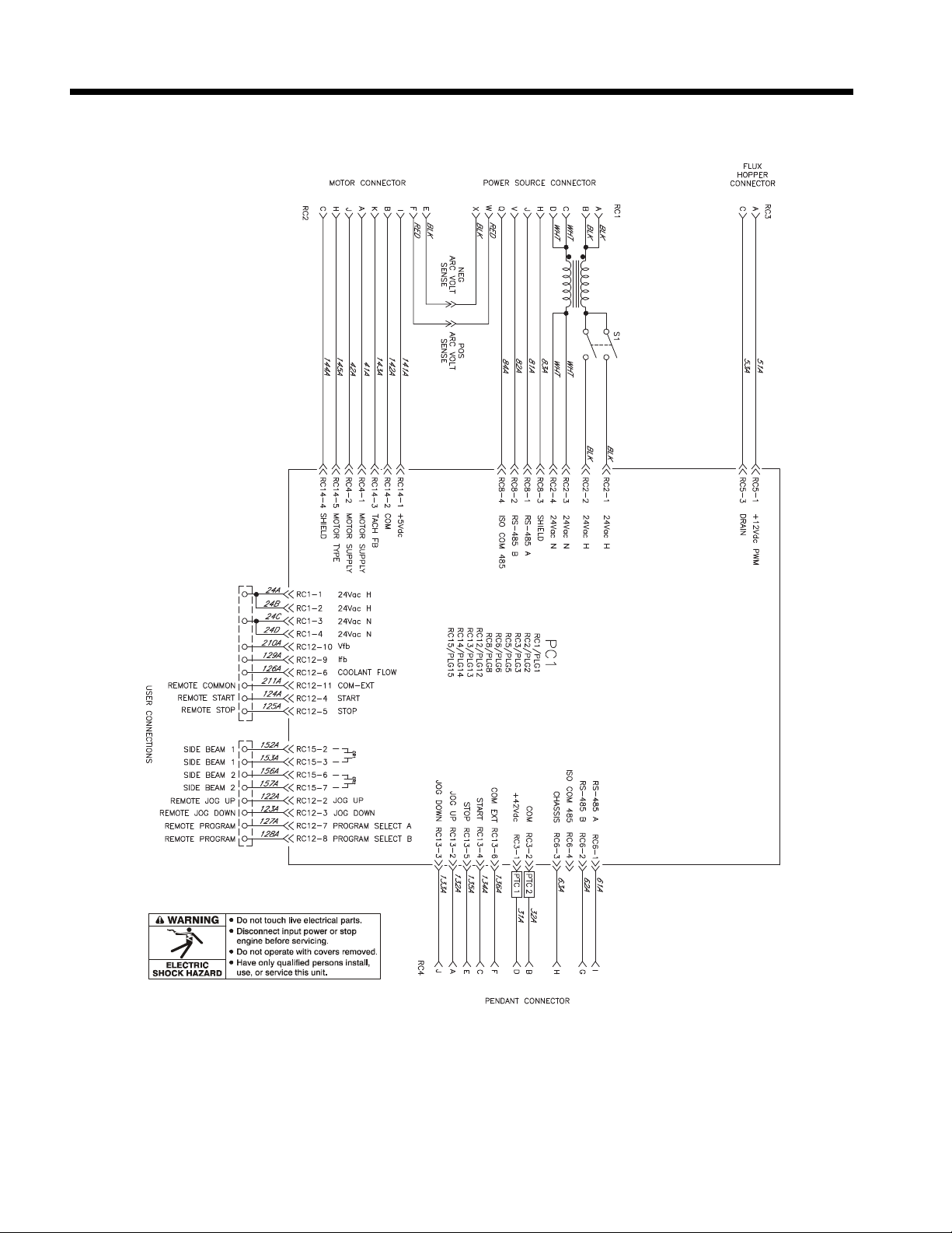
SECTION 9 – ELECTRICAL DIAGRAMS
277430-A
Figure 9-1. Circuit Diagram For SubArc Motor Control Digital
OM-294120 Page 42
Page 48
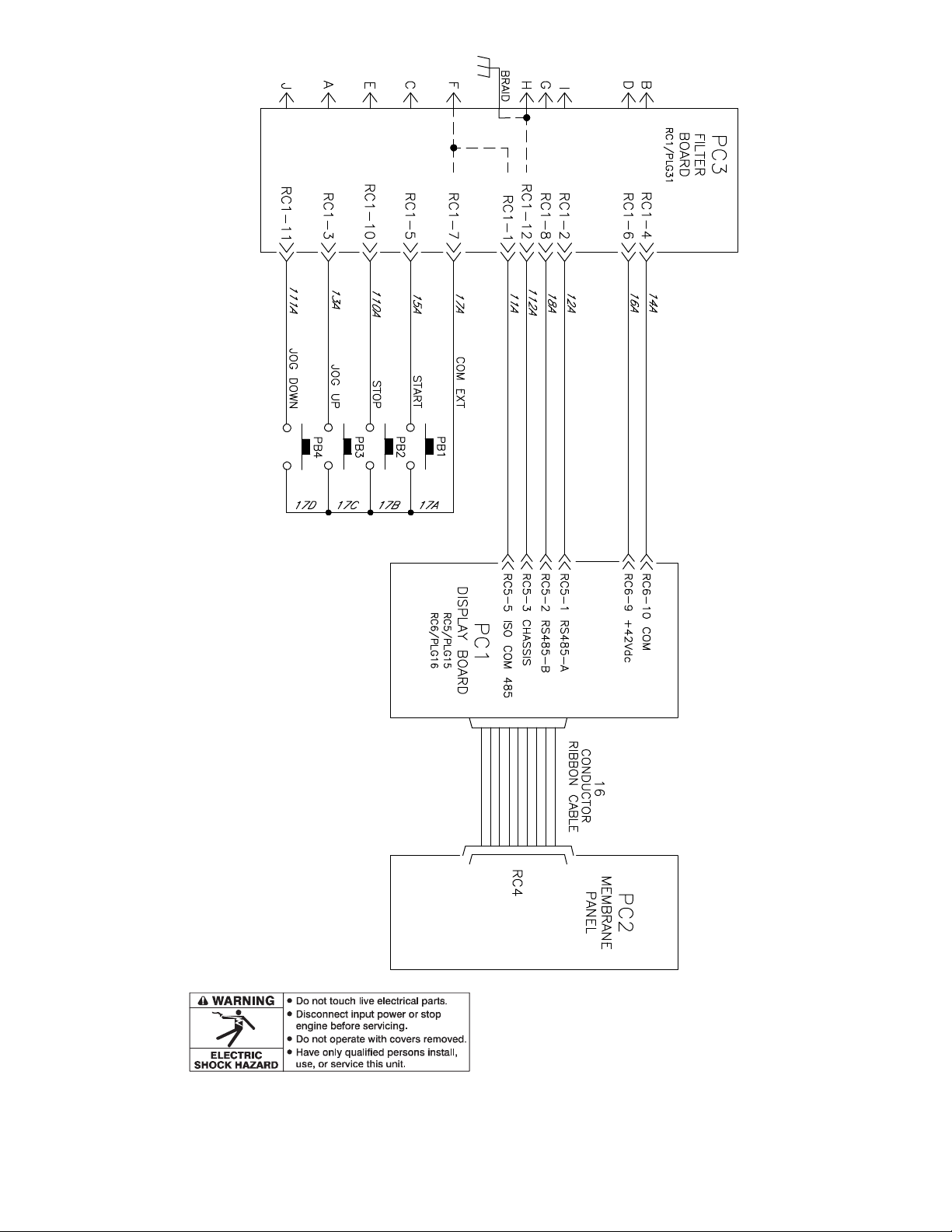
OM-294120 Page 43
277431-A
Figure 9-2. Circuit Diagram For SubArc Remote Pendant Digital
Page 49

Notes
Page 50

Notes
Page 51

Effective January 1, 2023 (Equipment with a serial number preface of ND or newer)
This limited warranty supersedes all previous Miller warranties and is exclusive with no other guarantees or war-
ranties expressed or implied.
LIMITED WARRANTY - Subject to the terms and
conditions below, Miller Electric Mfg. LLC, Appleton, Wisconsin, warrants to authorized distributors
that new Miller equipment sold after the effective
date of this limited warranty is free of defects in
material and workmanship at the time it is shipped
by Miller. THIS WARRANTY IS EXPRESSLY IN
LIEU OF ALL OTHER WARRANTIES, EXPRESS
OR IMPLIED, INCLUDING THE WARRANTIES
OF MERCHANTABILITY AND FITNESS.
Within the warranty periods listed below, Miller will
repair or replace any warranted parts or components that fail due to such defects in material or
workmanship. Miller must be notified in writing
within thirty (30) days of such defect or failure, at
which time Miller will provide instructions on the
warranty claim procedures to be followed. Notifications submitted as online warranty claims must
provide detailed descriptions of the fault and troubleshooting steps taken to diagnose failed parts.
Warranty claims that lack the required information
as defined in the Miller Service Operation Guide
(SOG) may be denied by Miller.
Miller shall honor warranty claims on warranted
equipment listed below in the event of a defect
within the warranty coverage time periods listed
below. Warranty time periods start on the delivery
date of the equipment to the end-user purchaser,
or 12 months after the equipment is shipped to a
US or Canada distributor, or 18 months after the
equipment is shipped to an international distributor,
whichever occurs first.
1 5 Years Parts — 3 Years Labor
l Original Main Power Rectifiers Only to Include
SCRs, Diodes, and Discrete Rectifier Modules
in non-inverter products
2 4 Years Parts (No Labor)
l Auto-Darkening ClearLight 2.0 Helmet Lenses
3 3 Years — Parts and Labor Unless Specified
l Auto-Darkening Helmet Lenses (No Labor)
l Engine Driven Welder/Generators (Including
EnPak) (NOTE: Engines are Warranted
Separately by the Engine Manufacturer.)
l Insight Welding Intelligence Products (Except
External Sensors)
l Inverter Power Sources
l Plasma Arc Cutting Power Sources
l Process Controllers
l Semi-Automatic and Automatic Wire Feeders
l Transformer/Rectifier Power Sources
4 2 Years — Parts and Labor
l Auto-Darkening Weld Masks (No Labor)
l Fume Extractors - Filtair 215, Capture 5, and
Industrial Collector Series
5 1 Year — Parts and Labor Unless Specified
l ArcReach Heater
l AugmentedArc, LiveArc, and MobileArc Weld-
ing Systems
l Automatic Motion Devices
l Bernard BTB Air-Cooled MIG Guns (No
Labor)
l CoolBelt, PAPR Blower, and PAPR Face
Shield (No Labor)
l Desiccant Air Dryer System
l Field Options (NOTE: Field options are cov-
ered for the remaining warranty period of
the product they are installed in, or for a
minimum of one year — whichever is
greater.)
l RFCS Foot Controls (Except RFCS-RJ45)
l Fume Extractors - Filtair 130, MWX and SWX
Series, ZoneFlow Extraction Arms and Motor
Control Box
l HF Units
l ICE/XT Plasma Cutting Torches (No Labor)
l Induction Heating Power Sources, Coolers
(NOTE: Digital Recorders are Warranted
Separately by the Manufacturer.)
l Insight Sensors
l Load Banks
l Motor-Driven Guns (except Spoolmate
Spoolguns)
l Positioners and Controllers
l Racks (For Housing Multiple Power Sources)
l Running Gear/Trailers
l Subarc Wire Drive Assemblies
l Supplied Air Respirator (SAR) Boxes and
Panels
l TIG Torches (No Labor)
l Tregaskiss Guns (No Labor)
l Water Cooling Systems
l Wireless Remote Foot/Hand Controls and
Receivers
l Work Stations/Weld Tables (No Labor)
6 6 Months — Parts
l 12 Volt Automotive-Style Batteries
7 90 Days — Parts
l Accessories (Kits)
l ArcReach Heater Quick Wrap and Air Cooled
Cables
l Canvas Covers
l Induction Heating Coils and Blankets, Cables,
and Non-Electronic Controls
l MDX Series MIG Guns
l M-Guns
l MIG Guns, Subarc (SAW) Torches, and Exter-
nal Cladding Heads
l Remote Controls and RFCS-RJ45
l Replacement Parts (No labor)
l Spoolmate Spoolguns
Miller’s True Blue
to:
1. Consumable components; such as contact
tips, cutting nozzles, contactors, brushes,
relays, work station table tops and welding
curtains, or parts that fail due to normal
wear. (Exception: brushes and relays are
covered on all engine-driven products.)
2. Items furnished by Miller, but manufactured by
others, such as engines or trade accessories.
These items are covered by the manufacturer’s
warranty, if any.
3. Equipment that has been modified by any party
other than Miller, or equipment that has been
®
Limited Warranty shall not apply
improperly installed, improperly operated or
misused based upon industry standards, or
equipment which has not had reasonable and
necessary maintenance, or equipment which
has been used for operation outside of the
specifications for the equipment.
4. Defects caused by accident, unauthorized repair, or improper testing.
MILLER PRODUCTS ARE INTENDED FOR
COMMERCIAL AND INDUSTRIAL USERS
TRAINED AND EXPERIENCED IN THE USE AND
MAINTENANCE OF WELDING EQUIPMENT.
The exclusive remedies for warranty claims are, at
Miller’s option, either: (1) repair; or (2) replacement; or, if approved in writing by Miller, (3) the
pre-approved cost of repair or replacement at an
authorized Miller service station; or (4) payment of
or credit for the purchase price (less reasonable
depreciation based upon use). Products may not
be returned without Miller’s written approval. Return shipment shall be at customer’s risk and
expense.
The above remedies are F. O.B. Appleton, WI, or
Miller’s authorized service facility. Transportation
and freight are the customer’s responsibility. TO
THE EXTENT PERMITTED BY LAW, THE REMEDIES HEREIN ARE THE SOLE AND EXCLUSIVE REMEDIES REGARDLESS OF THE LEGAL
THEORY. IN NO EVENT SHALL MILLER BE LIABLE FOR DIRECT, INDIRECT, SPECIAL, INCIDENTAL OR CONSEQUENTIAL DAMAGES
(INCLUDING LOSS OF PROFIT) REGARDLESS
OF THE LEGAL THEORY. ANY WARRANTY NOT
PROVIDED HEREIN AND ANY IMPLIED WARRANTY, GUARANTY, OR REPRESENTATION, INCLUDING ANY IMPLIED WARRANTY OF
MERCHANTABILITY OR FITNESS FOR PARTICULAR PURPOSE, ARE EXCLUDED AND DISCLAIMED BY MILLER.
Some US states do not allow limiting the duration
of an implied warranty or the exclusion of certain
damages, so the above limitations may not apply
to you. This warranty provides specific legal rights,
and other rights may be available depending on
your state. In Canada, some provinces provide additional warranties or remedies, and to the extent
the law prohibits their waiver, the limitations set out
above may not apply. This Limited Warranty provides specific legal rights, and other rights may be
available, but may vary by province.
Warranty Questions?
Call 1-800-4-A-MILLER for
your local Miller distributor.
Your distributor also gives you...
Service
You always get the fast, reliable response you
need. Most replacement parts can be in your
hands in 24 hours.
Support
Need fast answers to the tough welding questions? The expertise of the distributor and Miller
is there to help you, every step of the way.
Page 52

Owner’s Record
Please complete and retain with your personal records.
Model Name Serial/Style Number
Purchase Date
Distributor
Address
City
State Zip
(Date which equipment was delivered to original customer.)
For Service
Contact a DISTRIBUTOR or SERVICE AGENCY near you.
Always provide Model Name and Serial/Style Number.
Contact your Distributor for:
Welding Supplies and Consumables
Options and Accessories
Personal Protective Equipment (PPE)
Contact the Delivering Carrier to:
Service and Repair Replacement Parts
Training (Schools, Videos, Books)
Welding Process Handbooks
To locate a Distributor or Service Agency visit
www.millerwelds.com or call 1-800-4-A-Miller
File a claim for loss or damage during
shipment.
For assistance in filing or settling claims, contact your distributor and/or equipment manufacturer’s Transportation Department.
Miller Electric Mfg. LLC
An Illinois Tool Works Company
1635 West Spencer Street
Appleton, WI 54914 USA
International Headquarters–USA
USA Phone: 920-735-4505
USA & Canada FAX: 920-735-4134
International FAX: 920-735-4125
For International Locations Visit
www.MillerWelds.com
ORIGINAL INSTRUCTIONS – PRINTED IN USA © Miller Electric Mfg. LLC 2023-05
 Loading...