

Page 1
OM-1595 176 878F
December 2002
Processes
MIG (GMAW) Welding
Pulsed MIG (GMAW-P)
Flux Cored (FCAW) Welding
Submerged (SAW) Welding
Description
Automatic Welding
Automatic M
Visit our website at
www.MillerWelds.com
Page 2

From Miller to You
Thank you and congratulations on choosing Miller. Now you can get
the job done and get it done right. We know you don’t have time to do
it any other way.
That’s why when Niels Miller first started building arc welders in 1929,
he made sure his products offered long-lasting value and superior
quality. Like you, his customers couldn’t afford anything less. Miller
products had to be more than the best they could be. They had to be the
best you could buy.
Today, the people that build and sell Miller products continue the
tradition. They’re just as committed to providing equipment and service
that meets the high standards of quality and value established in 1929.
This Owner’s Manual is designed to help you get the most out of your
Miller products. Please take time to read the Safety precautions. They
will help you protect yourself against potential hazards on the worksite.
We’ve made installation and operation quick
and easy. With Miller you can count on years
of reliable service with proper maintenance.
And if for some reason the unit needs repair,
there’s a Troubleshooting section that will
help you figure out what the problem is. The
Miller is the first welding
equipment manufacturer in
the U.S.A. to be registered to
the ISO 9001:2000 Quality
System Standard.
parts list will then help you to decide the
exact part you may need to fix the problem.
Warranty and service information for your
particular model are also provided.
Working as hard as you do
– every power source from
Miller is backed by the most
hassle-free warranty in the
business.
Miller Electric manufactures a full line
of welders and welding related equipment.
For information on other quality Miller
products, contact your local Miller distributor to receive the latest full
line catalog orindividual catalog sheets. To locate your nearest
distributor or service agency call 1-800-4-A-Miller, or visit us at
www.MillerWelds.com on the web.
Miller offers a Technical
Manual which provides
more detailed service and
parts information for your
unit. T o obtain a Technical
Manual, contact your local
distributor. Your distributor
can also supply you with
Welding Process Manuals
such as SMAW, GTAW,
GMAW, and GMA W-P.
Page 3

OM-1595
TABLE OF CONTENTS
SECTION 1 – SAFETY PRECAUTIONS - READ BEFORE USING 1. . . . . . . . . . . . . . . . . . . . . . . . . . . .
1-1. Symbol Usage 1. . . . . . . . . . . . . . . . . . . . . . . . . . . . . . . . . . . . . . . . . . . . . . . . . . . . . . . . . . . . . . . .
1-2. Arc Welding Hazards 1. . . . . . . . . . . . . . . . . . . . . . . . . . . . . . . . . . . . . . . . . . . . . . . . . . . . . . . . . .
1-3. Additional Symbols For Installation, Operation, And Maintenance 3. . . . . . . . . . . . . . . . . . . . .
1-4. Principal Safety Standards 3. . . . . . . . . . . . . . . . . . . . . . . . . . . . . . . . . . . . . . . . . . . . . . . . . . . . .
1-5. EMF Information 4. . . . . . . . . . . . . . . . . . . . . . . . . . . . . . . . . . . . . . . . . . . . . . . . . . . . . . . . . . . . . .
SECTION 1 – CONSIGNES DE SECURITE – LIRE AVANT UTILISATION 5. . . . . . . . . . . . . . . . . . . . .
1-1. Signification des symboles 5. . . . . . . . . . . . . . . . . . . . . . . . . . . . . . . . . . . . . . . . . . . . . . . . . . . . .
1-2. Dangers relatifs au soudage à l’arc 5. . . . . . . . . . . . . . . . . . . . . . . . . . . . . . . . . . . . . . . . . . . . . .
1-3. Dangers supplémentaires en relation avec l’installation, le fonctionnement
et la maintenance 7. . . . . . . . . . . . . . . . . . . . . . . . . . . . . . . . . . . . . . . . . . . . . . . . . . . . . . . . . . . . .
1-4. Principales normes de sécurité 8. . . . . . . . . . . . . . . . . . . . . . . . . . . . . . . . . . . . . . . . . . . . . . . . . .
1-5. Information sur les champs électromagnétiques 8. . . . . . . . . . . . . . . . . . . . . . . . . . . . . . . . . . . .
SECTION 2 – SPECIFICATIONS 9. . . . . . . . . . . . . . . . . . . . . . . . . . . . . . . . . . . . . . . . . . . . . . . . . . . . . . . . .
2-1. Weld Control 9. . . . . . . . . . . . . . . . . . . . . . . . . . . . . . . . . . . . . . . . . . . . . . . . . . . . . . . . . . . . . . . . .
2-2. Operator Pendant 9. . . . . . . . . . . . . . . . . . . . . . . . . . . . . . . . . . . . . . . . . . . . . . . . . . . . . . . . . . . . .
SECTION 3 – INSTALLATION 10. . . . . . . . . . . . . . . . . . . . . . . . . . . . . . . . . . . . . . . . . . . . . . . . . . . . . . . . . . .
3-1. Typical Equipment Location 10. . . . . . . . . . . . . . . . . . . . . . . . . . . . . . . . . . . . . . . . . . . . . . . . . . . . .
3-2. Mounting Hole Layout 10. . . . . . . . . . . . . . . . . . . . . . . . . . . . . . . . . . . . . . . . . . . . . . . . . . . . . . . . . .
3-3. Connection Diagram 11. . . . . . . . . . . . . . . . . . . . . . . . . . . . . . . . . . . . . . . . . . . . . . . . . . . . . . . . . . .
3-4. Control Settings On Deltaweld 452/652 Ampere Model Welding Power Source 11. . . . . . . . .
3-5. Control Settings On Dimension 452 Or 652 Ampere Model Welding Power Source 12. . . . .
3-6. Control Settings On XMT 304 Inverter Model Welding Power Source 13. . . . . . . . . . . . . . . . .
3-7. Control Settings On Invision 456P Inverter Model Welding Power Source 14. . . . . . . . . . . . .
3-8. Setting Switches On Maxtron 450 Ampere Inverter Model Welding Power Source 14. . . . . .
3-9. Weld Cable Connections 15. . . . . . . . . . . . . . . . . . . . . . . . . . . . . . . . . . . . . . . . . . . . . . . . . . . . . . .
3-10. Bottom Panel Connections 15. . . . . . . . . . . . . . . . . . . . . . . . . . . . . . . . . . . . . . . . . . . . . . . . . . . . .
3-11. Installing Gas Supply 16. . . . . . . . . . . . . . . . . . . . . . . . . . . . . . . . . . . . . . . . . . . . . . . . . . . . . . . . . .
3-12. Input/Output Connections 17. . . . . . . . . . . . . . . . . . . . . . . . . . . . . . . . . . . . . . . . . . . . . . . . . . . . . .
3-13. Analog Designators* 17. . . . . . . . . . . . . . . . . . . . . . . . . . . . . . . . . . . . . . . . . . . . . . . . . . . . . . . . . . .
3-14. Input Designators* 18. . . . . . . . . . . . . . . . . . . . . . . . . . . . . . . . . . . . . . . . . . . . . . . . . . . . . . . . . . . .
3-15. Output Designators* 19. . . . . . . . . . . . . . . . . . . . . . . . . . . . . . . . . . . . . . . . . . . . . . . . . . . . . . . . . . .
3-16. Special Input Designators* 19. . . . . . . . . . . . . . . . . . . . . . . . . . . . . . . . . . . . . . . . . . . . . . . . . . . . .
3-17. Installing Hub 19. . . . . . . . . . . . . . . . . . . . . . . . . . . . . . . . . . . . . . . . . . . . . . . . . . . . . . . . . . . . . . . . .
3-18. Installing Spool-Type Wire And Adjusting Hub Tension 20. . . . . . . . . . . . . . . . . . . . . . . . . . . . . .
3-19. Installing Optional Reel-Type Wire 20. . . . . . . . . . . . . . . . . . . . . . . . . . . . . . . . . . . . . . . . . . . . . . .
3-20. Connecting Optional Pendant To Microprocessor Weld Control 21. . . . . . . . . . . . . . . . . . . . . . .
SECTION 4 – OPERATIONAL TERMS 21. . . . . . . . . . . . . . . . . . . . . . . . . . . . . . . . . . . . . . . . . . . . . . . . . . .
SECTION 5 – OPERATION 23. . . . . . . . . . . . . . . . . . . . . . . . . . . . . . . . . . . . . . . . . . . . . . . . . . . . . . . . . . . . .
5-1. Safety Equipment 23. . . . . . . . . . . . . . . . . . . . . . . . . . . . . . . . . . . . . . . . . . . . . . . . . . . . . . . . . . . . .
5-2. Front Panel Controls 23. . . . . . . . . . . . . . . . . . . . . . . . . . . . . . . . . . . . . . . . . . . . . . . . . . . . . . . . . . .
5-3. Main Display 24. . . . . . . . . . . . . . . . . . . . . . . . . . . . . . . . . . . . . . . . . . . . . . . . . . . . . . . . . . . . . . . . .
5-4. Control LED’s 24. . . . . . . . . . . . . . . . . . . . . . . . . . . . . . . . . . . . . . . . . . . . . . . . . . . . . . . . . . . . . . . .
5-5. Control Push Buttons 24. . . . . . . . . . . . . . . . . . . . . . . . . . . . . . . . . . . . . . . . . . . . . . . . . . . . . . . . . .
5-6. Emergency Stop Push Button 25. . . . . . . . . . . . . . . . . . . . . . . . . . . . . . . . . . . . . . . . . . . . . . . . . . .
5-7. Power Switch 25. . . . . . . . . . . . . . . . . . . . . . . . . . . . . . . . . . . . . . . . . . . . . . . . . . . . . . . . . . . . . . . .
5-8. Weld Enable Button Or User I/O Weld Enable 25. . . . . . . . . . . . . . . . . . . . . . . . . . . . . . . . . . . . . .
5-9. Manual Weld Button Or User I/O Test W eld 25. . . . . . . . . . . . . . . . . . . . . . . . . . . . . . . . . . . . . . . .
5-10. Mode Select Button 26. . . . . . . . . . . . . . . . . . . . . . . . . . . . . . . . . . . . . . . . . . . . . . . . . . . . . . . . . . .
5-11. Parameter Select Button 27. . . . . . . . . . . . . . . . . . . . . . . . . . . . . . . . . . . . . . . . . . . . . . . . . . . . . . .
5-12. Parameter Increase And Decrease Buttons 28. . . . . . . . . . . . . . . . . . . . . . . . . . . . . . . . . . . . . . .
5-13. Shielding Gas 29. . . . . . . . . . . . . . . . . . . . . . . . . . . . . . . . . . . . . . . . . . . . . . . . . . . . . . . . . . . . . . . .
5-14. Sequence Of GMAW , GMAW-P, GMAW Spot, And FCAW 29. . . . . . . . . . . . . . . . . . . . . . . . . . .
5-15. Sequence Of SAW 29. . . . . . . . . . . . . . . . . . . . . . . . . . . . . . . . . . . . . . . . . . . . . . . . . . . . . . . . . . . .
5-16. Optional Pendant Controls 30. . . . . . . . . . . . . . . . . . . . . . . . . . . . . . . . . . . . . . . . . . . . . . . . . . . . . .
SECTION 6 – SETTING A MIG WELDING PROGRAM 31. . . . . . . . . . . . . . . . . . . . . . . . . . . . . . . . . . . . . .
6-1. Changing To Mig In The Process Mode 31. . . . . . . . . . . . . . . . . . . . . . . . . . . . . . . . . . . . . . . . . . .
6-2. Setting Weld Sequence Display 32. . . . . . . . . . . . . . . . . . . . . . . . . . . . . . . . . . . . . . . . . . . . . . . . .
6-3. Setting Crater Sequence Display 33. . . . . . . . . . . . . . . . . . . . . . . . . . . . . . . . . . . . . . . . . . . . . . . .
6-4. Setting Burnback Sequence Display 33. . . . . . . . . . . . . . . . . . . . . . . . . . . . . . . . . . . . . . . . . . . . .
6-5. Setting Postflow Sequence Display 34. . . . . . . . . . . . . . . . . . . . . . . . . . . . . . . . . . . . . . . . . . . . . .
6-6. Setting Preflow Sequence Display 34. . . . . . . . . . . . . . . . . . . . . . . . . . . . . . . . . . . . . . . . . . . . . . .
6-7. Setting Run-In Sequence Display 34. . . . . . . . . . . . . . . . . . . . . . . . . . . . . . . . . . . . . . . . . . . . . . . .
Page 4

TABLE OF CONTENTS (Continued)
SECTION 7 – STANDARD PULSE WELDING PROGRAMS 35. . . . . . . . . . . . . . . . . . . . . . . . . . . . . . . . .
7-1. Pulse MIG Programs 35. . . . . . . . . . . . . . . . . . . . . . . . . . . . . . . . . . . . . . . . . . . . . . . . . . . . . . . . . .
7-2. Standard Pulse Welding Programs 35. . . . . . . . . . . . . . . . . . . . . . . . . . . . . . . . . . . . . . . . . . . . . . .
7-3. Program 1 – .035 ER 70S-3, Argon-Oxy 35. . . . . . . . . . . . . . . . . . . . . . . . . . . . . . . . . . . . . . . . . .
7-4. Program 2 – .045” ER 70S-3, Argon-Oxy 36. . . . . . . . . . . . . . . . . . . . . . . . . . . . . . . . . . . . . . . . .
7-5. Program 3 – .052 ER 70S-3, Argon-Oxy 36. . . . . . . . . . . . . . . . . . . . . . . . . . . . . . . . . . . . . . . . . .
7-6. Program 4 – .035” ER 309, Argon - CO2 37. . . . . . . . . . . . . . . . . . . . . . . . . . . . . . . . . . . . . . . . . .
7-7. Program 5 – .045” ER 309, Argon - CO2 37. . . . . . . . . . . . . . . . . . . . . . . . . . . . . . . . . . . . . . . . . .
7-8. Program 6 – 3/64” ER 4043, Argon 38. . . . . . . . . . . . . . . . . . . . . . . . . . . . . . . . . . . . . . . . . . . . . . .
7-9. Program 7 – 3/64” ER 5356, Argon 38. . . . . . . . . . . . . . . . . . . . . . . . . . . . . . . . . . . . . . . . . . . . . . .
7-10. Program 8 – .035” Nickel Alloy, Argon - He 39. . . . . . . . . . . . . . . . . . . . . . . . . . . . . . . . . . . . . . . .
7-11. Program 1 – .035” ER 4043, Argon 39. . . . . . . . . . . . . . . . . . . . . . . . . . . . . . . . . . . . . . . . . . . . . . .
7-12. Program 2 – 3/64” ER 4043, Argon 40. . . . . . . . . . . . . . . . . . . . . . . . . . . . . . . . . . . . . . . . . . . . . . .
7-13. Program 3 – 1/16” ER 4043, Argon 40. . . . . . . . . . . . . . . . . . . . . . . . . . . . . . . . . . . . . . . . . . . . . . .
7-14. Program 4 – .035” ER 5356, Argon 41. . . . . . . . . . . . . . . . . . . . . . . . . . . . . . . . . . . . . . . . . . . . . . .
7-15. Program 5 – 3/64” ER 5356, Argon 41. . . . . . . . . . . . . . . . . . . . . . . . . . . . . . . . . . . . . . . . . . . . . . .
7-16. Program 6 – 1/16” ER 5356, Argon 42. . . . . . . . . . . . . . . . . . . . . . . . . . . . . . . . . . . . . . . . . . . . . . .
7-17. Program 7 – 3/64” ER 5356, Argon 42. . . . . . . . . . . . . . . . . . . . . . . . . . . . . . . . . . . . . . . . . . . . . . .
7-18. Program 8 – .035” ER 5356, Argon 43. . . . . . . . . . . . . . . . . . . . . . . . . . . . . . . . . . . . . . . . . . . . . . .
SECTION 8 – SETTING STANDARD PULSE WELDING PROGRAMS 45. . . . . . . . . . . . . . . . . . . . . . . .
8-1. Weld Cycle 45. . . . . . . . . . . . . . . . . . . . . . . . . . . . . . . . . . . . . . . . . . . . . . . . . . . . . . . . . . . . . . . . . .
8-2. Setting Weld Sequence Display 45. . . . . . . . . . . . . . . . . . . . . . . . . . . . . . . . . . . . . . . . . . . . . . . . .
8-3. Setting Crater Sequence Display 46. . . . . . . . . . . . . . . . . . . . . . . . . . . . . . . . . . . . . . . . . . . . . . . .
8-4. Setting Burnback Sequence Display 46. . . . . . . . . . . . . . . . . . . . . . . . . . . . . . . . . . . . . . . . . . . . .
8-5. Setting Postflow Sequence Display 46. . . . . . . . . . . . . . . . . . . . . . . . . . . . . . . . . . . . . . . . . . . . . .
8-6. Setting Preflow Sequence Display 47. . . . . . . . . . . . . . . . . . . . . . . . . . . . . . . . . . . . . . . . . . . . . . .
8-7. Setting Run-In Sequence Display 47. . . . . . . . . . . . . . . . . . . . . . . . . . . . . . . . . . . . . . . . . . . . . . . .
SECTION 9 – TEACHING A PULSE WELDING PROGRAM 48. . . . . . . . . . . . . . . . . . . . . . . . . . . . . . . . .
9-1. Pulse Waveforms And Explanation Of Terms 48. . . . . . . . . . . . . . . . . . . . . . . . . . . . . . . . . . . . . .
9-2. Typical Teach Point Settings And Resulting Synergic Setting 49. . . . . . . . . . . . . . . . . . . . . . . . .
9-3. Selecting And/Or Redefining Teach Point Wire Feed Speed 50. . . . . . . . . . . . . . . . . . . . . . . . . .
9-4. Setting Teach Point Parameters On The Setup Panel 51. . . . . . . . . . . . . . . . . . . . . . . . . . . . . . .
9-5. Changing To Adaptive Pulse Welding 52. . . . . . . . . . . . . . . . . . . . . . . . . . . . . . . . . . . . . . . . . . . . .
SECTION 10 – USING THE DATA CARD OPTION 53. . . . . . . . . . . . . . . . . . . . . . . . . . . . . . . . . . . . . . . . .
10-1. Installing Data Card 53. . . . . . . . . . . . . . . . . . . . . . . . . . . . . . . . . . . . . . . . . . . . . . . . . . . . . . . . . . .
10-2. Using The Data Card 53. . . . . . . . . . . . . . . . . . . . . . . . . . . . . . . . . . . . . . . . . . . . . . . . . . . . . . . . . .
10-3. Naming Programs And Writing To Card 54. . . . . . . . . . . . . . . . . . . . . . . . . . . . . . . . . . . . . . . . . . .
10-4. Reading From Card 55. . . . . . . . . . . . . . . . . . . . . . . . . . . . . . . . . . . . . . . . . . . . . . . . . . . . . . . . . . .
10-5. Reading (Or Deleting) From An Empty Card 55. . . . . . . . . . . . . . . . . . . . . . . . . . . . . . . . . . . . . . .
10-6. Deleting Programs From Card 56. . . . . . . . . . . . . . . . . . . . . . . . . . . . . . . . . . . . . . . . . . . . . . . . . . .
SECTION 11 – SETUP 57. . . . . . . . . . . . . . . . . . . . . . . . . . . . . . . . . . . . . . . . . . . . . . . . . . . . . . . . . . . . . . . . .
11-1. Setup Menu 57. . . . . . . . . . . . . . . . . . . . . . . . . . . . . . . . . . . . . . . . . . . . . . . . . . . . . . . . . . . . . . . . . .
11-2. Accessing The Setup Menu 59. . . . . . . . . . . . . . . . . . . . . . . . . . . . . . . . . . . . . . . . . . . . . . . . . . . . .
11-3. Example Of Setting Output A In Setup 60. . . . . . . . . . . . . . . . . . . . . . . . . . . . . . . . . . . . . . . . . . . .
11-4. Selecting Wire Type 60. . . . . . . . . . . . . . . . . . . . . . . . . . . . . . . . . . . . . . . . . . . . . . . . . . . . . . . . . . .
11-5. Resetting Memory 61. . . . . . . . . . . . . . . . . . . . . . . . . . . . . . . . . . . . . . . . . . . . . . . . . . . . . . . . . . . . .
11-6. Starting Method For A Program 61. . . . . . . . . . . . . . . . . . . . . . . . . . . . . . . . . . . . . . . . . . . . . . . . . .
11-7. Remote Program Setting 62. . . . . . . . . . . . . . . . . . . . . . . . . . . . . . . . . . . . . . . . . . . . . . . . . . . . . . .
SECTION 12 – MAINTENANCE & TROUBLESHOOTING 63. . . . . . . . . . . . . . . . . . . . . . . . . . . . . . . . . . .
12-1. Routine Maintenance 63. . . . . . . . . . . . . . . . . . . . . . . . . . . . . . . . . . . . . . . . . . . . . . . . . . . . . . . . . .
12-2. Circuit Breaker CB1 And Fuse F1 63. . . . . . . . . . . . . . . . . . . . . . . . . . . . . . . . . . . . . . . . . . . . . . . .
12-3. Replacing The Hub Assembly 64. . . . . . . . . . . . . . . . . . . . . . . . . . . . . . . . . . . . . . . . . . . . . . . . . . .
12-4. Error Messages 65. . . . . . . . . . . . . . . . . . . . . . . . . . . . . . . . . . . . . . . . . . . . . . . . . . . . . . . . . . . . . .
12-5. Interface Board PC5 Diagnostic LED’s67. . . . . . . . . . . . . . . . . . . . . . . . . . . . . . . . . . . . . . . . . . . .
12-6. Customer Interface Board PC4 Diagnostic LED’s68. . . . . . . . . . . . . . . . . . . . . . . . . . . . . . . . . . .
SECTION 13 – ELECTRICAL DIAGRAMS 70. . . . . . . . . . . . . . . . . . . . . . . . . . . . . . . . . . . . . . . . . . . . . . . .
SECTION 14 – PARTS LIST 88. . . . . . . . . . . . . . . . . . . . . . . . . . . . . . . . . . . . . . . . . . . . . . . . . . . . . . . . . . . .
OPTIONS AND ACCESSORIES
WARRANTY
Page 5

Automatic M SET-UP INFORMATION
Please fill out the following information when setting up your equipment. It can be used for your records and also
be valuable if you ever need to call for service.
Model: Automatic M, Serial Number:
Software Version
SET-UP INFORMATION (found in set-up menu)
System: mig only Start: maintain
pulse mig momentary
Range: min V Arc Error: off on
max V VMonitor: off on
min A Volts
max A Time
Security: off on AMonitor: off on
Access: off on Time:
Mig Type: dvc off on Amperage:
Voltage: 17 pin Vsense Range:
Arc Start: standard hot Stick Check: off on
Flow: off on Output A: off or setting:
Polarity: off on On at
Jog IPM: Off at
Arc Time: Output B: off or setting:
Feed Wire: ipm mpm On at
Wire Type: hardwire softwire Off at
Shutdown: off on Burnback: normal retract
Program: panel remote Skip Weld: off on
OTHER IMPORTANT INFORMATION
Wire Size: Type: Gas:
Program#: factory custom
Mig or Pulse: Wire Speed: Voltage/Trim: Travel Speed:
Weld Cable Size: Approx. Length:
Material Type: Thickness: Type of Joint:
Page 6

Page 7
SECTION 1 – SAFETY PRECAUTIONS - READ BEFORE USING
1-1. Symbol Usage
Means Warning! Watch Out! There are possible hazards
with this procedure! The possible hazards are shown in
the adjoining symbols.
som _nd_7/02
Marks a special safety message.
Means “Note”; not safety related.
1-2. Arc Welding Hazards
The symbols shown below are used throughout this manual to
call attention to and identify possible hazards. When you see
the symbol, watch out, and follow the related instructions to
avoid the hazard. The safety information given below is only
a summary of the more complete safety information found in
the Safety Standards listed in Section 1-4. Read and follow all
Safety Standards.
Only qualified persons should install, operate, maintain, and
repair this unit.
During operation, keep everybody, especially children, away.
ELECTRIC SHOCK can kill.
Touching live electrical parts can cause fatal shocks
or severe burns. The electrode and work circuit is
electrically live whenever the output is on. The input
live when power is on. In semiautomatic or automatic wire welding, the
wire, wire reel, drive roll housing, and all metal parts touching the
welding wire are electrically live. Incorrectly installed or improperly
grounded equipment is a hazard.
Do not touch live electrical parts.
Wear dry, hole-free insulating gloves and body protection.
Insulate yourself from work and ground using dry insulating mats
or covers big enough to prevent any physical contact with the work
or ground.
Do not use AC output in damp areas, if movement is confined, or if
there is a danger of falling.
Use AC output ONLY if required for the welding process.
If AC output is required, use remote output control if present on
unit.
Disconnect input power or stop engine before installing or
servicing this equipment. Lockout/tagout input power according to
OSHA 29 CFR 1910.147 (see Safety Standards).
Properly install and ground this equipment according to its
Owner’s Manual and national, state, and local codes.
Always verify the supply ground – check and be sure that input
power cord ground wire is properly connected to ground terminal in
disconnect box or that cord plug is connected to a properly
grounded receptacle outlet.
When making input connections, attach proper grounding conduc-
tor first – double-check connections.
Frequently inspect input power cord for damage or bare wiring –
replace cord immediately if damaged – bare wiring can kill.
Turn off all equipment when not in use.
Do not use worn, damaged, undersized, or poorly spliced cables.
Do not drape cables over your body.
power circuit and machine internal circuits are also
This group of symbols means Warning! Watch Out! possible
ELECTRIC SHOCK, MOVING PARTS, and HOT PARTS hazards.
Consult symbols and related instructions below for necessary actions
to avoid the hazards.
If earth grounding of the workpiece is required, ground it directly
with a separate cable.
Do not touch electrode if you are in contact with the work, ground,
or another electrode from a different machine.
Use only well-maintained equipment. Repair or replace damaged
parts at once. Maintain unit according to manual.
Wear a safety harness if working above floor level.
Keep all panels and covers securely in place.
Clamp work cable with good metal-to-metal contact to workpiece
or worktable as near the weld as practical.
Insulate work clamp when not connected to workpiece to prevent
contact with any metal object.
Do not connect more than one electrode or work cable to any
single weld output terminal.
SIGNIFICANT DC VOLTAGE exists after removal of
input power on inverters.
Turn Off inverter, disconnect input power, and discharge input
capacitors according to instructions in Maintenance Section
before touching any parts.
FUMES AND GASES can be hazardous.
Welding produces fumes and gases. Breathing
these fumes and gases can be hazardous to your
health.
Keep your head out of the fumes. Do not breathe the fumes.
If inside, ventilate the area and/or use exhaust at the arc to remove
welding fumes and gases.
If ventilation is poor, use an approved air-supplied respirator.
Read the Material Safety Data Sheets (MSDSs) and the
manufacturer’s instructions for metals, consumables, coatings,
cleaners, and degreasers.
Work in a confined space only if it is well ventilated, or while
wearing an air-supplied respirator. Always have a trained watchperson nearby. Welding fumes and gases can displace air and
lower th e oxygen level causing injury or death. Be sure the breathing air is safe.
Do not weld in locations near degreasing, cleaning, or spraying op-
erations. The heat and rays of the arc can react with vapors to form
highly toxic and irritating gases.
Do not weld on coated metals, such as galvanized, lead, or
cadmium plated steel, unless the coating is removed from the weld
area, the area is well ventilated, and if necessary, while wearing an
air-supplied respirator. The coatings and any metals containing
these elements can give off toxic fumes if welded.
OM-1595 Page 1
Page 8
ARC RAYS can burn eyes and skin.
BUILDUP OF GAS can injure or kill.
Arc rays from the welding process produce intense
visible and invisible (ultraviolet and infrared) rays
that can burn eyes and skin. Sparks fly off from the
weld.
Wear a welding helmet fitted with a proper shade of filter to protect
your face and eyes when welding or watching (see ANSI Z49.1
and Z87.1 listed in Safety Standards).
Wear approved safety glasses with side shields under your
helmet.
Use protective screens or barriers to protect others from flash and
glare; warn others not to watch the arc.
Wear protective clothing made from durable, flame-resistant mate-
rial (leather and wool) and foot protection.
WELDING can cause fire or explosion.
Welding on closed containers, such as tanks,
drums, or pipes, can cause them to blow up. Sparks
can fly off from the welding arc. The flying sparks, hot
burns. Accidental contact of electrode to metal objects can cause
sparks, explosion, overheating, or fire. Check and be sure the area is
safe before doing any welding.
Protect yourself and others from flying sparks and hot metal.
Do not weld where flying sparks can strike flammable material.
Remove all flammables within 35 ft (10.7 m) of the welding arc. If
this is not possible, tightly cover them with approved covers.
Be alert that welding sparks and hot materials from welding can
easily go through small cracks and openings to adjacent areas.
Watch for fire, and keep a fire extinguisher nearby .
Be aware that welding on a ceiling, floor, bulkhead, or partition can
cause fire on the hidden side.
Do not weld on closed containers such as tanks, drums, or pipes,
unless they are properly prepared according to AWS F4.1 (see
Safety Standards).
Connect work cable to the work as close to the welding area as
practical to prevent welding current from traveling long, possibly
unknown paths and causing electric shock and fire hazards.
Do not use welder to thaw frozen pipes.
Remove stick electrode from holder or cut off welding wire at
contact tip when not in use.
Wear oil-free protective garments such as leather gloves, heavy
shirt, cuffless trousers, high shoes, and a cap.
Remove any combustibles, such as a butane lighter or matches,
from your person before doing any welding.
workpiece, and hot equipment can cause fires and
FLYING METAL can injure eyes.
Welding, chipping, wire brushing, and grinding
cause sparks and flying metal. As welds cool,
they can throw off slag.
Wear approved safety glasses with side
shields even under your welding helmet.
Shut off shielding gas supply when not in use.
Always ventilate confined spaces or use
approved air-supplied respirator.
HOT PARTS can cause severe burns.
Do not touch hot parts bare handed.
Allow cooling period before working on gun or
torch.
MAGNETIC FIELDS can affect pacemakers.
Pacemaker wearers keep away.
Wearers should consult their doctor before
going near arc welding, gouging, or spot
welding operations.
NOISE can damage hearing.
Noise from some processes or equipment can
damage hearing.
Wear approved ear protection if noise level is
high.
CYLINDERS can explode if damaged.
Shielding gas cylinders contain gas under high
pressure. If damaged, a cylinder can explode. Since
gas cylinders are normally part of the welding
process, be sure to treat them carefully.
Protect compressed gas cylinders from excessive heat, mechani-
cal shocks, slag, open flames, sparks, and arcs.
Install cylinders in an upright position by securing to a stationary
support or cylinder rack to prevent falling or tipping.
Keep cylinders away from any welding or other electrical circuits.
Never drape a welding torch over a gas cylinder.
Never allow a welding electrode to touch any cylinder.
Never weld on a pressurized cylinder – explosion will result.
Use only correct shielding gas cylinders, regulators, hoses, and fit-
tings designed for the specific application; maintain them and
associated parts in good condition.
Turn face away from valve outlet when opening cylinder valve.
Keep protective cap in place over valve except when cylinder is i n
use or connected for use.
Read and follow instructions on compressed gas cylinders,
associated equipment, and CGA publication P-1 listed in Safety
Standards.
OM-1595 Page 2
Page 9
1-3. Additional Symbols For Installation, Operation, And Maintenance
FIRE OR EXPLOSION hazard.
Do not install or place unit on, over, or near
combustible surfaces.
Do not install unit near flammables.
Do not overload building wiring – be sure power supply system is
properly sized, rated, and protected to handle this unit.
FALLING UNIT can cause injury.
Use lifting eye to lift unit only, NOT running
gear, gas cylinders, or any other accessories.
Use equipment of adequate capacity to lift and
support unit.
If using lift forks to move unit, be sure forks are
long enough to extend beyond opposite side of
unit.
OVERUSE can cause OVERHEATING
Allow cooling period; follow rated duty cycle.
Reduce current or reduce duty cycle before
starting to weld again.
Do not block or filter airflow to unit.
STATIC (ESD) can damage PC boards.
MOVING PARTS can cause injury.
Keep away from moving parts such as fans.
Keep all doors, panels, covers, and guards
closed and securely in place.
H.F. RADIATION can cause interference.
High-frequency (H.F.) can interfere with radio
navigation, safety services, computers, and
communications equipment.
Have only qualified persons familiar with
electronic equipment perform this installation.
The user is responsible for having a qualified electrician prompt-
ly correct any interference problem resulting from the installation.
If notified by the FCC about interference, stop using the
equipment at once.
Have the installation regularly checked and maintained.
Keep high-frequency source doors and panels tightly shut, keep
spark gaps at correct setting, and use grounding and shielding to
minimize the possibility of interference.
Put on grounded wrist strap BEFORE handling
boards or parts.
Use proper static-proof bags and boxes to
store, move, or ship PC boards.
MOVING PARTS can cause injury.
Keep away from moving parts.
Keep away from pinch points such as drive
rolls.
WELDING WIRE can cause injury.
Do not press gun trigger until instructed to do
so.
Do not point gun toward any part of the body,
other people, or any metal when threading
welding wire.
ARC WELDING can cause interference.
Electromagnetic energy can interfere with
sensitive electronic equipment such as
computers and computer-driven equipment
such as robots.
Be sure all equipment in the welding area is
electromagnetically compatible.
To reduce possible interference, keep weld cables as short as
possible, close together, and down low, such as on the floor.
Locate welding operation 100 meters from any sensitive elec-
tronic equipment.
Be sure this welding machine is installed and grounded
according t o this manual.
If interference still occurs, the user must take extra measures
such as moving the welding machine, using shielded cables,
using line filters, or shielding the work area.
OM-1595 Page 3
Page 10

1-4. Principal Safety Standards
Safety i n W elding, Cutting, and Allied Processes, ANSI Standard Z49.1,
from American Welding Society, 550 N.W. LeJeune Rd, Miami FL 33126
(phone: 305-443-9353, website: www.aws.org).
Recommended Safe Practices for the Preparation for Welding and Cutting of Containers and Piping, American Welding Society Standard
AWS F4.1, from American Welding Society, 550 N.W. LeJeune Rd, Miami, FL 33126 (phone: 305-443-9353, website: www.aws.org).
National Electrical Code, NFPA Standard 70, from National Fire Protection Association, P.O. Box 9101, 1 Battery March Park, Quincy, MA
02269–9101 (phone: 617–770–3000, website: www.nfpa.org and www.
sparky.org).
Safe Handling of Compressed Gases in Cylinders, CGA Pamphlet P-1,
from Compressed Gas Association, 1735 Jefferson Davis Highway,
Suite 1004, Arlington, VA 22202–4102 (phone: 703–412–0900, web-
site: www.cganet.com).
Code for Safety in Welding and Cutting, CSA Standard W117.2, from
Canadian Standards Association, Standards Sales, 178 Rexdale
1-5. EMF Information
Considerations About Welding And The Effects Of Low Frequency
Electric And Ma g netic Fields
Welding current, as it flows through welding cables, will cause electromagnetic fields. There has been and still is some concern about such
fields. However, after examining more than 500 studies spanning 17
years of research, a special blue ribbon committee of the National
Research Council concluded that: “The body of evidence, in the
committee’s judgment, has not demonstrated that exposure to power-
frequency electric and magnetic fields is a human-health hazard.”
However, studies are still going forth and evidence continues to be
examined. Until the final conclusions of the research are reached, you
may wish to minimize your exposure to electromagnetic fields when
welding or cutting.
To reduce magnetic fields in the workplace, use the following
procedures:
Boulevard, Rexdale, Ontario, Canada M9W 1R3 (phone:
800–463–6727 or in Toronto 416–747–4044, website: www.csa–international.org).
Practice For Occupational And Educational Eye And Face Protection,
ANSI Standard Z87.1, from American National Standards Institute, 11
West 42nd Street, New York, NY 10036–8002 (phone: 212–642–4900,
website: www.ansi.org).
Standard for Fire Prevention During Welding, Cutting, and Other Hot
Work, NFP A Standard 51B, from National Fire Protection Association,
P .O. Box 9101, 1 Battery March Park, Quincy, MA 02269 –9101 (phone:
617–770–3000, website: www.nfpa.org and www. sparky.org).
OSHA, Occupational Safety and Health Standards for General Industry, Title 29, Code of Federal Regulations (CFR), Part 1910, Subpart Q,
and Part 1926, Subpart J, from U.S. Government Printing Office, Superintendent of Documents, P.O. Box 371954, Pittsburgh, PA 15250 (there
are 10 Regional Offices––phone for Region 5, Chicago, is
312–353–2220, website: www.osha.gov).
1. Keep cables close together by twisting or taping them.
2. Arrange cables to one side and away from the operator.
3. Do not coil or drape cables around your body.
4. Keep welding power source and cables as far away from operator as practical.
5. Connect work clamp to workpiece as close to the weld as possible.
About Pacemakers:
Pacemaker wearers consult your doctor first. If cleared by your doctor,
then following the above procedures is recommended.
OM-1595 Page 4
Page 11
SECTION 1 – CONSIGNES DE SÉCURITÉ – À LIRE AVANT
UTILISATION
som _nd_fre 7/02
1-1. Signification des symboles
Signifie « Mise en garde. Faire preuve de vigilance. »
Cette procédure présente des risques identifiés par les
symboles adjacents aux directives.
Ce groupe de symboles signifie « Mise en garde. Faire preuve de vigi-
Identifie un message de sécurité particulier .
Signifie « NOTA » ; n’est pas relatif à la sécurité.
1-2. Dangers relatifs au soudage à l’arc
lance. » Il y a des dangers liés aux CHOCS ÉLECTRIQUES, aux
PIÈCES EN MOUVEMENT et aux PIÈCES CHAUDES. Se reporter
aux symboles et aux directives ci-dessous afin de connaître les mesures à prendre pour éviter tout danger.
Les symboles ci-après sont utilisés tout au long du présent
manuel pour attirer l’attention sur les dangers potentiels et les
identifier. Lorsqu’on voit un symbole, faire preuve de vigilance et
suivre les directives mentionnées afin d’éviter tout danger. Les
consignes de sécurité énoncées ci-après ne font que résumer le
contenu des normes de sécurité mentionnées à la section 1–4.
Lire et respecter toutes ces normes.
L’installation, l’utilisation, l’entretien et les réparations ne doi-
vent être confiés qu’à des personnes qualifiées.
Pendant l’utilisation de l’appareil, tenir à l’écart toute personne,
en particulier les enfants.
LES DÉCHARGES ÉLECTRIQUES
peuvent être mortelles.
Un simple contact avec des pièces sous tension peut
causer une électrocution ou des blessures graves.
L’électrode et le circuit de soudage sont sous tension
d’entrée et les circuits internes de l’appareil sont également sous tension.
En soudage semi–automatique ou automatique, le fil, le dévidoir, le
logement des galets d’entraînement et les pièces métalliques en contact
avec le fil de soudage sont sous tension. Tout mat ériel mal installé ou mal
mis à la terre présente un danger.
Ne jamais toucher aux pièces électriques sous tension.
Porter des gants et des vêtements de protection secs et exempts de
trous.
S’isoler de la pièce et de la terre au moyen de tapis ou autres disposi-
tifs isolants suffisamment grands pour empêcher tout contact
physique avec la pièce ou la terre.
Ne pas se servir d’une source de courant alternatif dans les zones humi-
des, les endroits confinés ou là où on risque de tomber.
Ne se servir d’une source de courant alternatif QUE si le procédé de souda-
ge l’exige.
Si l ’utilisation d’une source de courant alternatif s’avère nécessaire, se ser-
vir de la fonction de télécommande si l’appareil en est équipé.
Couper l’alimentation ou arrêter le moteur avant de procéder à l’instal-
lation, à la réparation ou à l’entretien de l’appareil. Couper/étiqueter
l’alimentation selon la norme OSHA 29 CFR 1910.147 (voir les normes de sécurité).
Installer et mettre à la terre correctement l’appareil conformément à
son manuel d’utilisation et aux codes nationaux, provinciaux et
municipaux.
Toujours v érifier la terre du cordon d’alimentation – Vérifier et s’assu-
rer que le fil de terre du cordon d’alimentation est bien raccordé à la
borne de terre du sectionneur ou que la fiche du cordon est raccordée
à une prise correctement mise à la terre.
Pour exécuter les branchements d’entrée, fixer d’abord le conducteur
de mise à la terre adéquat et contre–vérifier les connexions.
Vérifier fréquemment le cordon d’alimentation et s’assurer qu’il n’est
ni endommagé ni dénudé ; le remplacer immédiatement s’il est endommagé – tout câble dénudé peut causer une électrocution.
Mettre l’appareil hors tension quand on ne l’utilise pas.
Ne pas utiliser de câbles usés, endommagés, de calibre insuffisant ou
mal épissés.
Ne pas s’enrouler les câbles autour du corps.
Si la pièce soudée doit être mise à la terre, le faire directement avec un
câble distinct.
Ne pas toucher l’électrode quand on est en contact avec la pièce, la
terre ou une électrode d’une autre machine.
dès que l’appareil est en fonctionnement. Le circuit
N’utiliser que du matériel en bon état. Réparer ou remplacer sur–le–
champ les pièces endommagées. Entretenir l’appareil conformément
au présent manuel.
Porter un harnais de sécurité quand on travaille en hauteur.
Maintenir solidement en place tous les panneaux et capots.
Fixer le câble de retour de façon à obtenir un bon contact métal sur
métal avec la pièce à souder ou la table de travail, le plus près possible
de la soudure.
Ne pas connecter plus d’une électrode ou plus d’un câble de masse à un
même terminal de sortie.
Il subsiste un COURANT CONTINU IMPORTANT
dans les convertisseurs après la suppression de
l’alimentation électrique.
Arrêter les convertisseurs, débrancher le courant électrique et dé-
charger les condensateurs d’alimentation selon les instructions
énoncées à la section Entretien avant de toucher les pièces.
LES FUMÉES ET LES GAZ peuvent
être dangereux.
Le soudage génère des fumées et des gaz dont
l’inhalation peut être dangereuse pour la santé.
Se tenir à distance des fumées et ne pas les inhaler.
À l’intérieur, ventiler la zone et/ou utiliser un dispositif d’aspiration au
niveau de l’arc pour l’évacuation des fumées et des gaz de soudage.
Si la ventilation est insuffisante, utiliser un respirateur à adduction
d’air agréé.
Lire les fiches techniques de santé–sécurité (FTSS) et les instruc-
tions du fabricant concernant les métaux, les consommables, les
revêtements, les nettoyants et les dégraisseurs.
Ne travailler dans un espace clos que s’il est bien ventilé ou porter un
respirateur à adduction d’air. Demander toujours à un surveillant dû-
ment formé de se tenir à proximité. Des fumées et des gaz de soudage
peuvent se substituer à l’air, abaisser la teneur en oxygène et causer
des lésions ou des accidents mortels. S’assurer que l’air est respirable.
Ne pas souder à proximité d’opérations de dégraissage, de nettoyage
ou de pulvérisation. La chaleur et les rayons de l’arc peuvent réagir en
présence de vapeurs et former des gaz hautement toxiques et irritants.
Ne pas souder de métaux munis d’un revêtement, tels que la tôle
d’acier galvanisée, plombée ou cadmiée, à moins que le revêtement
n’ait été enlevé dans la zone de soudage, que l’endroit soit bien venti-
lé, et si nécessaire, porter un respirateur à adduction d’air. Les
revêtements et tous les métaux renfermant ces éléments peuvent dé-
gager des fumées toxiques lorsqu’on les soude.
OM-1595 Page 5
Page 12
LES RAYONS DE L’ARC peuvent cau-
ser des brûlures oculaires et cutanées.
Le rayonnement de l’arc génère des rayons visibles et
invisibles intenses (ultraviolets et infrarouges) susceptibles de causer des brûlures oculaires et cutanées.
Des étincelles sont projetées pendant le soudage.
Porter un masque de soudage muni d’un filtre de la nuance adéquate
pour se protéger le visage et les yeux pendant le soudage ou pour regarder (voir les normes de sécurité ANSI Z49.1 et Z87.1).
Porter des lunettes de sécurité à écrans latéraux sous le masque.
Utiliser des écrans ou des barrières pour protéger les tiers de l’éclat
éblouissant ou aveuglant de l’arc ; leur demander de ne pas regarder
l’arc.
Porter des vêtements de protection en matière durable et ignifuge
(cuir ou laine) et des chaussures de sécurité.
LE SOUDAGE peut causer un incendie ou une explosion.
Le soudage effectué sur des récipients fermés tels que
des réservoirs, des fûts ou des conduites peut causer
leur éclatement. Des étincelles peuvent être projetées
pièces chaudes et les équipements chauds peuvent causer des
incendies et des brûlures. Le contact accidentel de l’électrode avec tout
objet métallique peut causer des étincelles, une explosion, un surchauffement ou un incendie. Avant de commencer le soudage, vérifier et
s’assurer que l’endroit ne présente pas de danger.
Se protéger et protéger les tiers de la projection d’étincelles et de mé-
tal chaud.
Ne pas souder à un endroit où des étincelles peuvent tomber sur des
substances inflammables.
Placer toutes les substances inflammables à une distance de 10,7 m
de l’arc de soudage . En cas d’impossibilité, les recouvrir soigneuse-
ment avec des protections agréées.
Des étincelles et des matières en fusion peuvent facilement passer
même par des fissures et des ouvertures de petites dimensions.
Surveiller tout déclenchement d’incendie et tenir un extincteur à proxi-
mité.
Le soudage effectué sur un plafond, un plancher, une paroi ou une
cloison peut déclencher un incendie de l’autre côté.
Ne pas souder des récipients fermés tels que des réservoirs, des fûts
ou des conduites, à moins qu’ils n’aient été préparés conformément à
l’AWS F4.1 (voir les normes de sécurité).
Brancher le câble sur la pièce le plus près possible de la zone de sou-
dage pour éviter que le courant ne circule sur une longue distance, par
des chemins inconnus, et ne cause des risques d’électrocution et d’incendie.
Ne pas utiliser le poste de soudage pour dégeler des conduites ge-
lées.
En cas de non utilisation, enlever la baguette d’électrode du porte–
électrode ou couper le fil au raz du tube–contact.
Porter des vêtements de protection exempts d’huile tels que des
gants en cuir, une chemise en tissu épais, des pantalons sans revers,
des chaussures montantes et un masque.
Avant de souder, retirer tout produit combustible de ses poches, tel
qu’un briquet au butane ou des allumettes.
de l’arc de soudure. La projection d’étincelles, les
LES PARTICULES PROJETÉES peuvent blesser les yeux.
Le soudage, le burinage, le passage de la pièce à
la brosse métallique et le meulage provoquent
ques. Pendant leur refroidissement, les soudures risquent de projeter du
laitier.
Porter des lunettes de sécurité à écrans latéraux agréés, même sous le
masque de soudage.
l’émission d’étincelles et de particules métalli-
LES ACCUMULATIONS DE GAZ peuvent causer des blessures ou même
la mort.
Couper l’alimentation en gaz protecteur en cas de
non utilisation.
Veiller toujours à bien ventiler les espaces confinés ou porter un respira-
teur à adduction d’air agréé.
LES PIÈCES CHAUDES peuvent causer des brûlures graves.
Ne pas toucher les pièces chaudes à main nue.
Prévoir une période de refroidissement avant
d’utiliser le pistolet ou la torche.
LES CHAMPS MAGNÉTIQUES peuvent
perturber le fonctionnement des stimulateurs cardiaques.
Les personnes qui portent un stimulateur cardiaque
doivent se tenir à distance.
Ils doivent consulter leur médecin avant de s’appro-
cher d’un lieu où on exécute des opérations de soudage à l’arc, de gougeage ou de soudage par points.
LE BRUIT peut affecter l’ouïe.
Le bruit de certains processus et équipements peut
affecter l’ouïe.
Porter des protecteurs d’oreille agréés si le niveau
sonore est trop élevé.
Les BOUTEILLES endommagées
peuvent exploser.
Les bouteilles de gaz protecteur contiennent du gaz
sous haute pression. Toute bouteille endommagée
peut exploser. Comme les bouteilles de gaz font
manipuler avec précaution.
Protéger les bouteilles de gaz comprimé de la chaleur excessive, des
chocs mécaniques, du laitier , des flammes nues, des étincelles et des
arcs.
Placer les bouteilles debout en les fixant dans un support stationnaire
ou dans un porte–bouteilles pour les empêcher de tomber ou de se
renverser.
Tenir les bouteilles éloignées des circuits de soudage ou autres cir-
cuits électriques.
Ne jamais poser une torche de soudage sur une bouteille de gaz.
Ne jamais mettre une électrode de soudage en contact avec une bou-
teille de gaz.
Ne jamais souder une bouteille contenant du gaz sous pression – elle
risquerait d’exploser.
N’utiliser que les bouteilles de gaz protecteur, régulateurs, tuyaux et
raccords adéquats pour l’application envisagée ; les maintenir en bon
état, ainsi que les pièces connexes.
Détourner la tête lorsqu’on ouvre la soupape d’une bouteille.
Laisser le capuchon protecteur sur la soupape, sauf en cas d’utilisa-
tion ou de branchement de la bouteille
Lire et suivr e les instructions concernant les bouteilles de gaz compri-
mé, les équipements associés et les publications P–1 de la CGA,
mentionnées dans les normes de sécurité.
normalement partie du procédé de soudage, les
OM-1595 Page 6
Page 13
1-3. Autres symboles relatifs à l’installation, au fonctionnement et à l’entretien de
l’appareil.
Risque D’INCENDIE OU D’EXPLO-
SION
Ne pas placer l’appareil sur une surface inflam-
mable, ni au–dessus ou à proximité d’elle.
Ne pas installer l’appareil à proximité de produits inflammables.
Ne pas surcharger l’installation électrique – s’assurer que l’alimen-
tation est correctement dimensionnée et protégée avant de mettre
l’appareil en service.
LA CHUTE DE L’APPAREIL peut
blesser.
N’utiliser que l’anneau de levage pour lever l’ap-
pareil. NE PAS utiliser le chariot, les bouteilles de
gaz ou tout autre accessoire.
Utiliser un engin de capacité adéquate pour lever
Si on utilise un chariot élévateur pour déplacer l’unité, s’assurer que
les fourches sont suffisamment longues pour dépasser du côté op-
posé de l’appareil.
l’appareil.
L’EMPLOI EXCESSIF peut FAIRE
SURCHAUFFER L’ÉQUIPEMENT.
Prévoir une période de refroidissement ; respec-
ter le cycle opératoire nominal.
Réduire le courant ou le cycle opératoire avant de
Ne pas obstruer les orifices ou filtrer l’alimentation en air du poste.
reprendre le soudage.
LES ORGANES MOBILES peuvent
causer des blessures.
Se tenir à l’écart des organes mobiles comme les
ventilateurs.
Maintenir fermés et bien fixés les portes,
panneaux, recouvrements et dispositifs de
protection.
LE RAYONNEMENT HAUTE FRÉ-
QUENCE (H. F.) risque de causer des
interférences.
Le rayonnement haute fréquence peut causer
des interférences avec les équipements de radionavigation et de communication, les services de
sécurité et les ordinateurs.
Ne demander qu’à des personnes qualifiées familiarisées avec les
équipements électroniques de faire fonctionner l’installation.
L’utilisateur est tenu de faire corriger rapidement par un électricien
qualifié les interférences causées par l’installation.
Si la Federal Communications Commission signale des interféren-
ces, arrêter immédiatement l’appareil.
Faire régulièrement contrôler et entretenir l’installation.
Maintenir soigneusement fermés les panneaux et les portes des sour-
ces de haute fréquence, maintenir le jeu d’éclatement au réglage
adéquat et utiliser une terre et un blindage pour réduire les interféren-
ces éventuelles.
LE SOUDAGE À L’ARC peut causer
des interférences.
LES CHARGES ÉLECTROSTATI-
QUES peuvent endommager les circuits imprimés.
Mettre un bracelet antistatique AVANT de mani-
puler des cartes ou des pièces.
Utiliser des pochettes et des boîtes antistatiques
pour stocker, déplacer ou expédier des cartes de
circuits imprimés.
LES PIÈCES MOBILES peuvent causer des blessures.
Se tenir à l’écart des pièces mobiles.
Se tenir à l’écart des points de coincement tels
que les dévidoirs.
LES FILS DE SOUDAGE peuvent causer des blessures.
Ne pas appuyer sur la gâchette avant d’en avoir
reçu l’instruction.
Ne pas diriger le pistolet vers soi, vers d’autres
personnes ou vers toute pièce mécanique en en-
gageant le fil de soudage.
L’énergie électromagnétique peut causer des
interférences avec l’équipement électronique
sensible tel que les ordinateurs et l’équipement
commandé par ordinateur tel que les robots.
Veiller à ce que tout l’équipement de la zone de soudage soit compati-
ble au point de vue électromagnétique.
Pour réduire la possibilité d’interférence, maintenir les câbles de sou-
dage aussi courts que possible, les grouper, et les poser aussi bas
que possible (par ex. : à terre).
Veiller à souder à une distance de 100 mètres de tout équipement
électronique sensible.
Veiller à ce que le poste de soudage soit posé et mis à la terre confor-
mément au présent manuel.
En cas d’interférences après exécution des directives précédentes, il
incombe à l’utilisateur de prendre des mesures supplémentaires telles que le déplacement du poste, l’utilisation de câbles blindés,
l’utilisation de filtres de ligne ou la pose de protecteurs dans la zone de
travail.
LES CHAMPS MAGNÉTIQUES peuvent
affecter les stimulateurs cardiaques.
Porteurs de stimulateur cardiaque, restez à dis-
tance.
Les porteurs d’un stimulateur cardiaque doivent
d’abord consulter leur médecin avant de s’appro-
cher des opérations de soudage à l’arc, de gou-
geage ou de soudage par points.
OM-1595 Page 7
Page 14

1-4. Principales normes de sécurité
Safety in Welding, Cutting, and Allied Processes, norme ANSI Z49.1,
de l’American W elding Society , 55 0 N .W. LeJeune Rd, Miami FL 33126
(téléphone : (305) 443–9353, site Web : www.aws.org).
Recommended Safe Practices for the Preparation for Welding and Cutting of Containers and Piping, norme American Welding Society AWS
F4.1, de l ’American Welding Society, 550 N.W. LeJeune Rd, Miami, FL
33126 ( t éléphone : (305) 443–9353, site Web : www.aws.org).
National Electrical Code, norme NFPA 70, de la National Fire Protection
Association, P.O. Box 9101, 1 Battery March Park, Quincy, MA
02269–9101 (téléphone : (617) 770–3000, sites Web : www.nfpa.org et
www.sparky.org).
Safe Handling of Compressed Gases in Cylinders, brochure CGA P–1,
de la Compressed Gas Association, 1735 Jefferson Davis Highway,
Suite 1004, Arlington, VA 22202–4102 (téléphone : (703) 412–0900,
site Web : w w w.cganet.com).
Code for Safety in Welding and Cutting, norme CSA W117.2, de la Canadian Standards Association, Standards Sales, 178 boulevard
Rexdale, Rexdale (Ontario) Canada M9W 1R3 (téléphone : (800)
463–6727 ou à Toronto : (416) 747–4044, site Web : www.csa–international.org).
Practice For Occupational And Educational Eye And Face Protection,
norme ANSI Z87.1, de l’American National Standards Institute, 11 West
42nd Street, New York, NY 10036–8002 (téléphone : (212) 642–4900,
site Web : www.ansi.org).
Standard for Fire Prevention During Welding, Cutting, and Other Hot
Work, norme NFPA 51B, de la National Fire Protection Association,
P.O. Box 9101, 1 Battery March Park, Quincy, MA 02269–9101 (télé-
phone : (617) 770–3000, site Web : www.nfpa.org et www.sparky.org).
OSHA, Occupational Safety and Health Standards for General Industry, Title 29, Code of Federal Regulations (CFR), Part 1910, Subpart Q,
and Part 1926, Subpart J, de l’U.S. Government Printing Office, Superintendent of Documents, P.O. Box 371954, Pittsburgh, PA 15250 (il y a
10 bureaux régionaux – Téléphone pour la Région 5, Chicago : (312)
353–2220, site Web : www.osha.gov).
1-5. Information sur les champs électromagnétiques
Données sur le soudage électrique et les ef fets des champs magnéti-
ques basse fréquence sur l’organisme
En parcourant les câbles de soudage, le courant crée des champs électromagnétiques. Les effets potentiels de tels champs restent
préoccupants. Cependant, après avoir examiné plus de 500 études qui
ont été faites pendant une période de recherche de 17 ans, un comité
de spécialistes du National Research Council a conclu : « L’accumula-
tion de preuves n’a pas démontré que l’exposition aux champs
magnétiques et aux champs électriques à haute fréquence constitue un
risque pour la santé humaine ». Toutefois, les études et l’examen des
preuves se poursuivent. En attendant les conclusions finales de la recherche, il serait souhaitable de réduire l’exposition aux champs
électromagnétiques pendant le soudage ou le coupage.
Afin de r éduire les champs électromagnétiques en milieu de travail, res-
pecter les consignes suivantes :
1. Garder les câbles ensemble en les torsadant ou en les fixant avec du
ruban ad h ésif.
2. Mettre tous les câbles du côté opposé à l’opérateur.
3. Ne pas s’enrouler les câbles autour du corps.
4. Garder le poste de soudage et les câbles le plus loin possible de soi.
5. Placer la pince de masse le plus près possible de la zone de soudage.
Consignes relatives aux stimulateurs cardiaques :
Les personnes qui portent un stimulateur cardiaque doivent avant tout
consulter leur médecin. Si ce dernier les déclare aptes, il leur est recommandé de respecter les consignes ci-dessus.
OM-1595 Page 8
Page 15
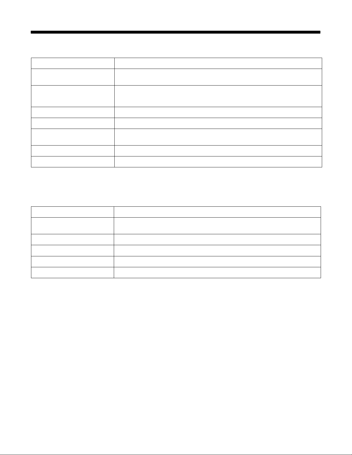
2-1. Weld Control
Specification Description
SECTION 2 – SPECIFICATIONS
Type Of Input Power From Welding
Power Source
Welding Power Source Type Constant Voltage (CV) DC, With Contactor And 14-Pin Remote Control For GMA W Welding
Wire Feed Speed Range* Standard: 50 To 780 ipm (1.3 To 19.8 mpm)
Wire Diameter Range .030 To .062 in (0.8 To 1.6 mm)
Welding Processes Gas Metal Arc (GMAW), Gas Metal Arc - Pulse (GMAW-P), Flux Cored Arc (FCAW), And
Overall Dimensions Length: 15 in (381 mm); Width: 16 in (406 mm); Height: 8-1/2 in (216 mm)
Weight Net: 33 lb (15 kg); Ship 38 lb (17.2 kg)
*These are the wire feed speed ranges while GMAW welding. While Pulse welding, the wire feed speed ranges may be more limited (see
Section 9).
Single-Phase 115 Volts AC, 3.5 Amperes, 50/60 Hertz
Constant Voltage (CV)/Constant Current (CC) DC Inverter, With Contactor And 14-Pin Remote
Control For GMAW-P Welding
Submerged Arc Welding (SAW)
2-2. Operator Pendant
Specification Description
Interconnecting Cord With Plugs (Not
Supplied)
Program Selection Eight Programs
10 ft (3 m), 30 ft (9.1 m), Or 50 ft (15.2 m)
Control Capacity Single Microprocessor Weld Control
Overall Dimensions Height: 11-3/4 in (298 mm); Width: 7-1/4 in (184 mm); Depth: 4 in (102 mm)
Weight Net: 2-5/8 lb (1.2 kg)
OM-1595 Page 9
Page 16
SECTION 3 – INSTALLATION
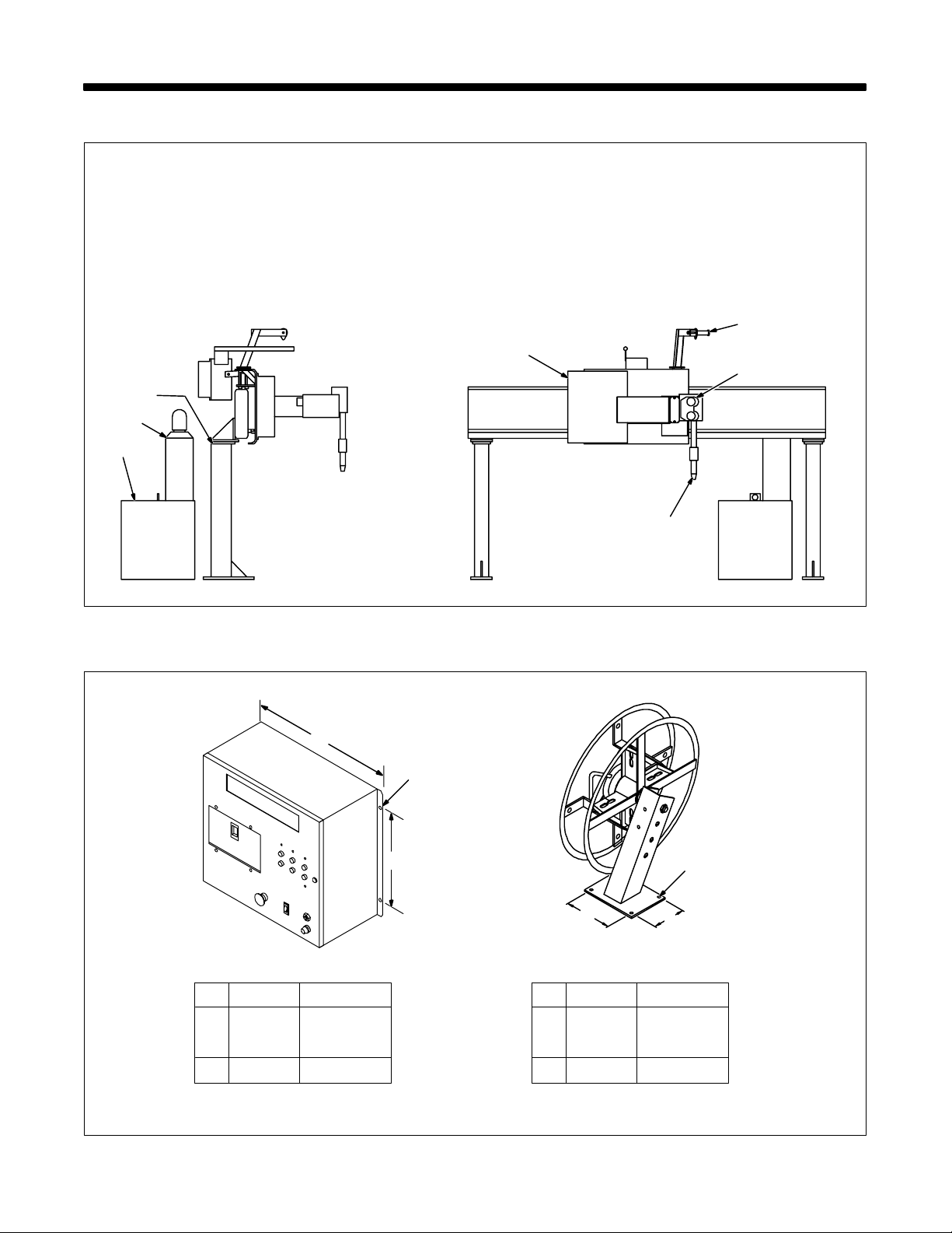
3-1. Typical Equipment Location
3
2
1
1 Welding Power Source
2 Gas Cylinder
3 Side Beam
4 Weld Control
5 Spool Support
6 Wire Drive Assembly
7 Automatic Welding Gun
5
4
6
3-2. Mounting Hole Layout
A
7
ST-131 138-A
C
B
D
Spool Support Assembly
(Shown With Optional Wire Assembly
F
E
OM-1595 Page 10
Inches Millimeters
A 16-7/8 429
B 11 279
C 3/8 Dia 9.5 Dia
Inches Millimeters
D 3-1/2 89
E 2-1/2 64
F 5/16 Dia 7.9 Dia
Ref. ST-801 440 / ST-080 486-C
Page 17
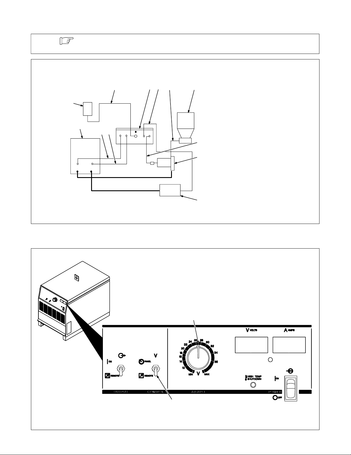
3-3. Connection Diagram
Note
Customer must supply wire drive assembly and drive rolls, gun, welding wire, weld cables,
control cables, and shielding gas or flux for desired application.
23
12
11
8
10
9
1
4
5
6
7
Adapter cord 043551 must be ordered when using an inverter power source equipped with
only a 14-socket receptacle.
1 Weld Control Bottom Panel
2 Voltage Sensing Cord
3 Accessory Equipment
Connection (Flux Valve,
Fixture, Remote Switch, Etc.)
4 Automatic Flux Valve
(Optional For SAW Welding)
5 Motor Control Cord
6 Wire Drive Assembly
7 Workpiece
8 Welding Power Source
9 Remote 14 Interconnecting
Cord
10 Remote 17 Interconnecting
Cord
11 Optional Pendant Control
12 Pendant Control
Interconnecting Cord
3-4. Control Settings On Deltaweld 452/652 Ampere Model Welding Power Source
Set controls as shown for all
welding processes when
using this interface unit.
1
2
1 Voltage Adjustment Control
2 Voltage Control Switch
Position o f Voltage Adjustment con-
trol does not matter when Voltage
Control switch is in REMOTE position.
ST-800 453 / Ref. ST-162 502-B
OM-1595 Page 11
Page 18
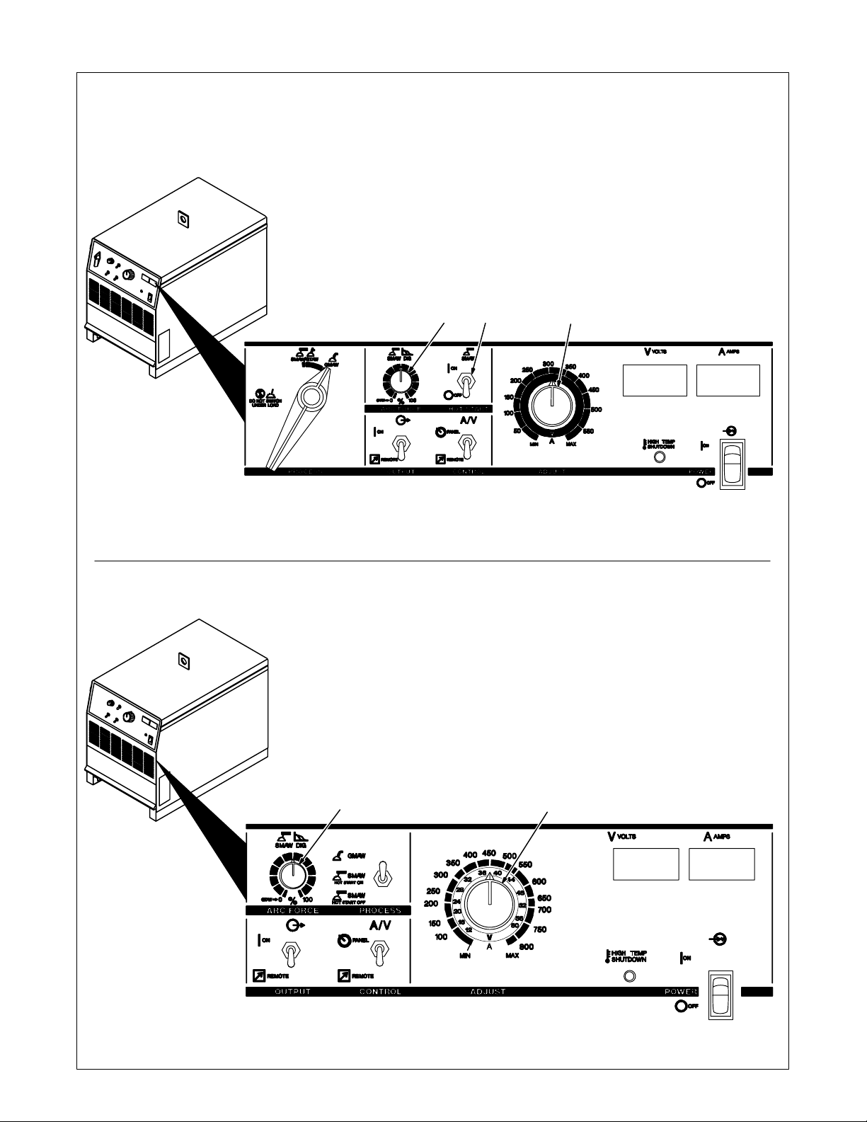
3-5. Control Settings On Dimension 452 Or 652 Ampere Model Welding Power Source
Dimension 452 Model
Set controls as shown for all
welding processes when using this interface unit.
132
1 Arc Force (Dig) Control
2 Hot Start Switch
3 Amperage/Voltage Adjustment
Control
Setting a t controls and switch position does not matter when Process
Selector switch is in GMAW position and remote Amperage/Voltage
Control switch is in REMOTE position.
26
24
28
22
20
18
16
14
12
30
32
34
36
Dimension 652 Model
Set switches as shown for all
welding processes when using this interface unit.
1
ST-800 166-B / Ref. ST-161 964-A
1 Arc Force (Dig) Control
2 Amperage/Voltage Adjustment
Control
Setting at controls does not matter
when Process Selector switch is in
GMAW position and remote Amperage/Voltage Control switch is in
REMOTE position.
2
OM-1595 Page 12
ST-800 091 / ST-162 500-A
Page 19
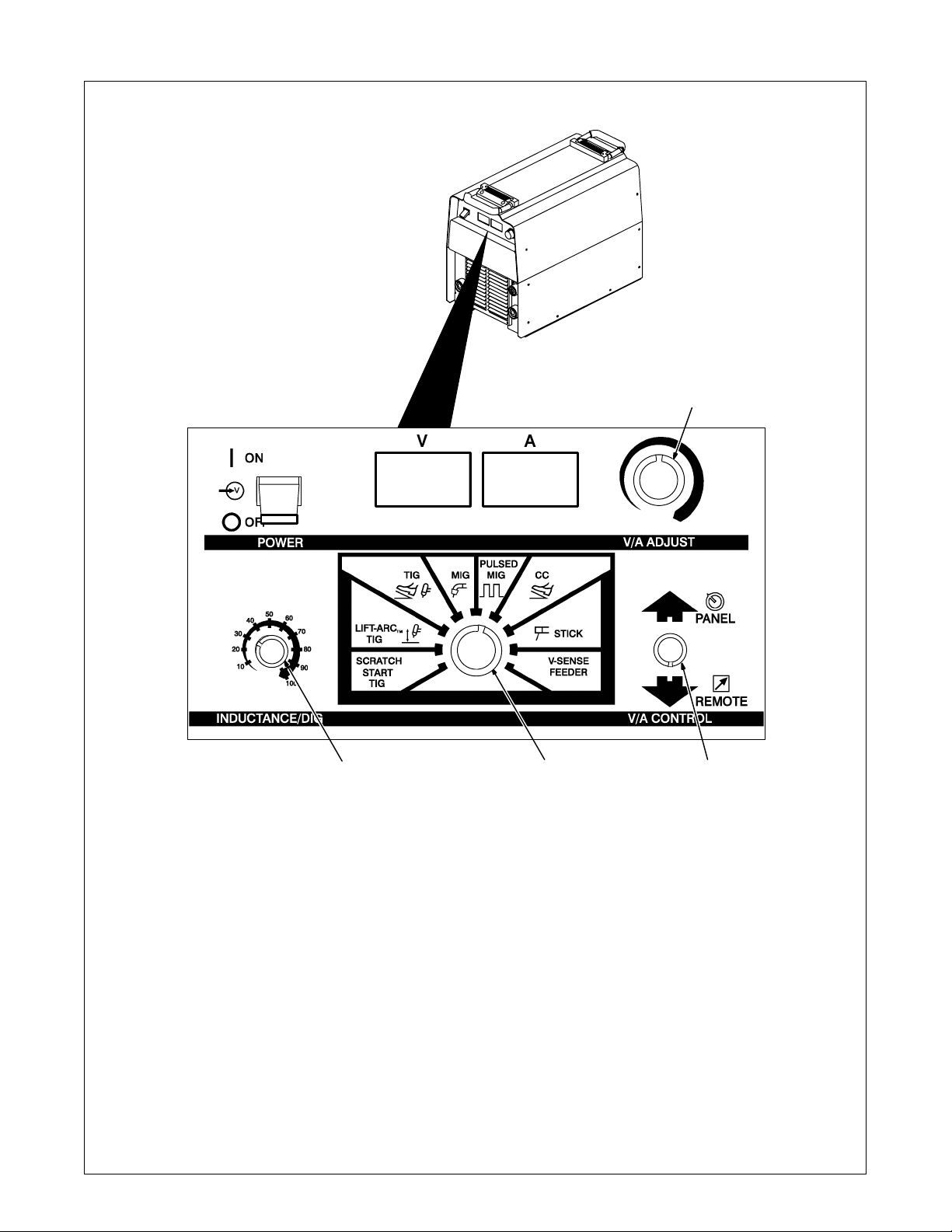
3-6. Control Settings On XMT 304 Inverter Model Welding Power Source
Set controls as shown for all
welding processes when
using this interface unit.
1
1 Voltage/Amperage Adjustment Control
2 Mode Switch
The Mode switch setting determines both the
process and output On/Off control. Source of
control (panel or remote) for the amount of
output i s selected on the V/A Control switch.
Unit does not support remote MIG to
PULSED MIG selection.
3 Voltage/Amperage Control Switch
For front panel control, place switch in Panel
position and use the V/A Adjust control.
234
For remote control, make connections to
Remote 14 receptacle, and place switch in
Remote position. Remote control is a percent of V/A Adjust control setting. V alue selected on V/A Adjust is maximum available
on remote.
4 Inductance/Dig Control
When set towards minimum, short-circuit
amperage at low arc voltage is the same as
normal welding amperage.
When set towards maximum, short-circuit
amperage is increased at low arc voltage to
ST-801 192 / Ref. ST-175 086
assist with arc starts as well as reduce sticking while welding.
Select setting best suited for application.
Control adjusts inductance when a MIG
(GMAW) position is selected on the mode
switch. Inductance determines the “wet-
ness” of the weld puddle. When set higher,
“wetness” (puddle fluidity) increases.
Inductance is only used in MIG
(nonpulsed) welding applications.
OM-1595 Page 13
Page 20
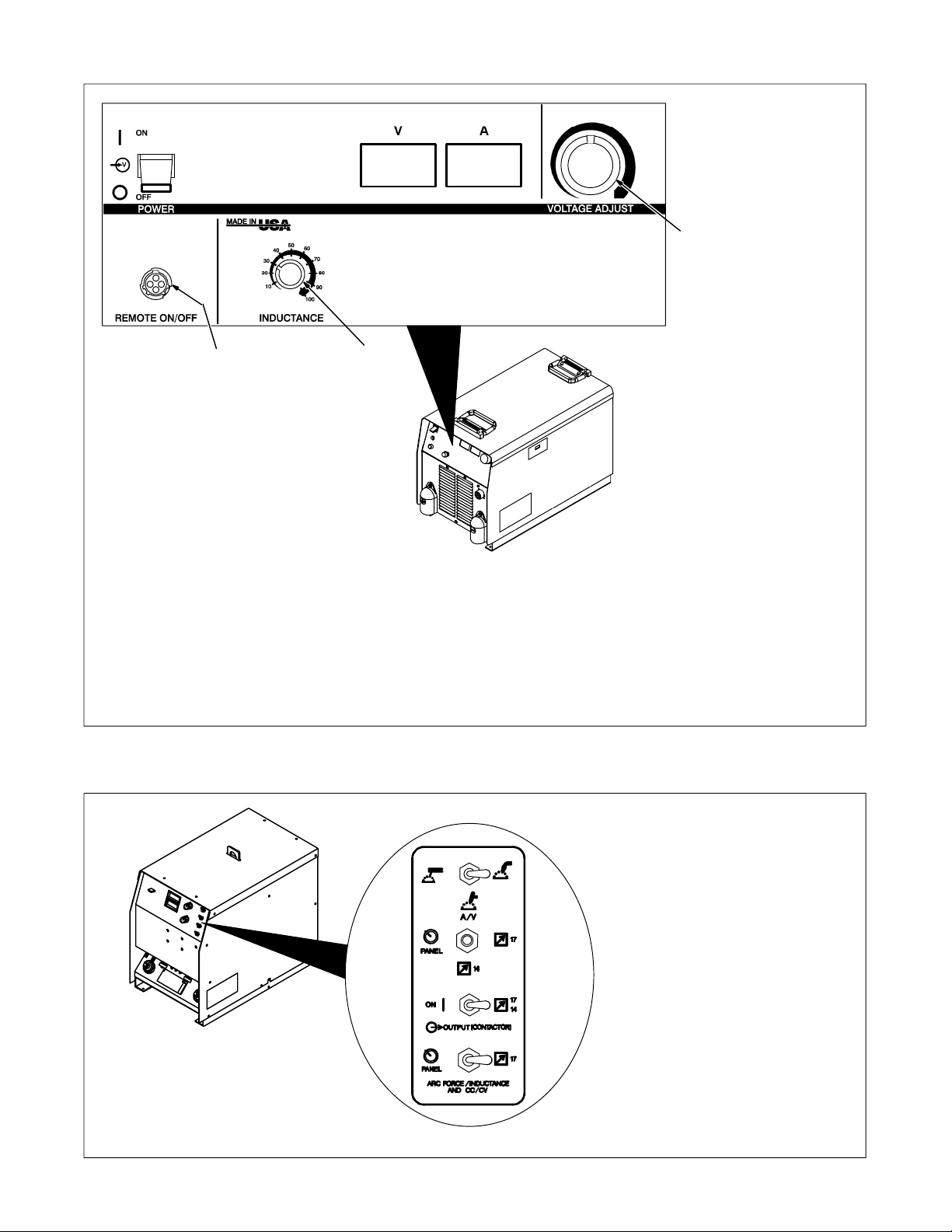
3-7. Control Settings On Invision 456P Inverter Model Welding Power Source
Set controls as shown for all
welding processes when
using this interface unit.
1
3
1 Voltage Adjustment Control
2 Inductance Control
Inductance determines the “wetness” of the
weld puddle. When set higher, “wetness”
(puddle fluidity) increases.
2
3 Remote On/Off Receptacle (Optional)
Sockets 1 and 2 are connected in parallel
with the Power On/Off switch. For remote
On/Off control, connect a suitable plug from
ST-801 718 / ST-180 311-B
a remote switch to the receptacle and place
front panel Power On/Off switch in Off position. Unit can then be turned On and Off
through the use of the remote switch.
3-8. Setting Switches On Maxtron 450 Ampere Inverter Model Welding Power Source
OM-1595 Page 14
Set switches as shown for all
welding processes when
using this interface unit.
Ref. ST-150 171-C / Ref. ST-165 852-B
Page 21
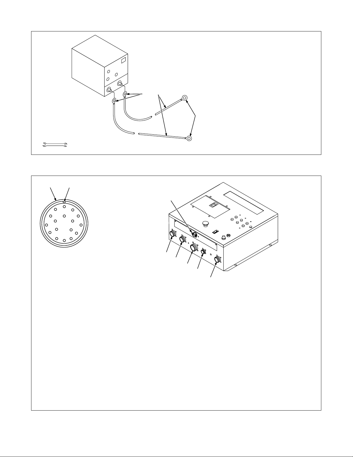
3-9. Weld Cable Connections
Tools Needed:
3/4 in
3-10. Bottom Panel Connections
1 Weld Output Cables
Determine tota l cable length in weld
circuit and maximum welding amperes according to welding power
source Owner’s Manual.
Do not use damaged cables.
2 Terminal Lug
Use lugs of proper amperage
1
2
2
capacity and hole size for
connecting to wire drive assembly
and work connection.
If weld cable connections are for
pulse welding, be sure to use 4/0
cables regardless of welding
speed.
sb6.1* 8/92 – Ref. S-0653
1
C
D
Example Receptacle
1 Receptacle
2 Keyway
3 14-Pin Receptacle (Connection To
Welding Power Source)
4 17-Pin Receptacle (Connection To
Welding Power Source With 17-Pin
Receptacle)
5 19-Socket Receptacle
(Motor/Shielding Gas Control
Connection To Motor Drive
Assembly)
6 37-Socket Receptacle (Optional
B
P
E
2
A
N
T
RS
G
F
M
L
K
J
H
8
3
4
6
7
5
Pendant Control Connection Or
User Interface Connection)
A customer supplied matching amphenol
plug (Part No. MS3106A28-21P) is required for user interface connection.
To connect matching interconnecting cord
to one of the above receptacles, align keyway, insert plug, and tighten threaded collar. Connect remaining end of cord to
matching receptacle on applicable equipment (see Section 3-3).
Ref. ST-801 440
7 4-Pin Receptacle (Optional External
Voltage Sensing Connection)
To connect interconnecting cord to receptacle, align keyway, insert plug, and tighten threaded collar.
Secure ring terminal on end of cord to
workpiece.
8 Interface Panel (User Connections)
Optional strain relief (Part No. 044 426)
allows routing user cord inside unit to
make connections at terminal strips for I/O
signals.
OM-1595 Page 15
Page 22
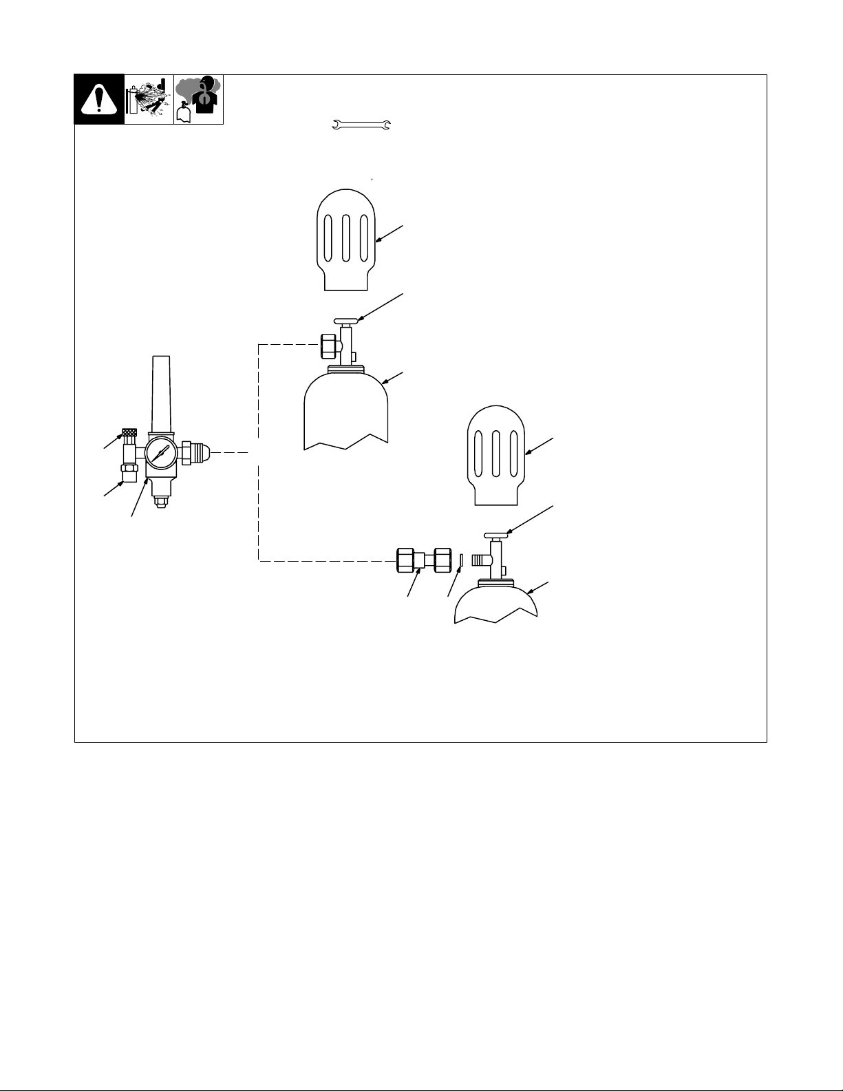
3-11. Installing Gas Supply
Tools Needed:
1-1/8, 5/8 in
running gear, wall, or other
stationary support so cylinder
cannot fall and break off valve.
1 Cap
2 Cylinder Valve
Remove cap, stand to side of valve,
and open valve slightly. Gas flow
blows dust and dirt from valve.
Obtain gas cylinder and chain to
1
Close valve.
3 Cylinder
4 Regulator/Flowmeter
Install so face is vertical.
2
5 Gas Hose Connection
Fitting has 5/8-18 right-hand
threads. Obtain and install gas
hose.
6 Flow Adjust
3
Typical flow rate is 20 cfh (cubic feet
per hour). Check wire
manufacturer’s recommended flow
rate.
Make sure flow adjust is closed
when opening cylinder to avoid
1
damage to the flowmeter.
6
OR
Argon Gas
7CO
Adapter
2
8 O-Ring
Install adapter with O-ring between
5
4
regulator/flowmeter and CO
2
cylinder.
2
7 8
3
CO2 Gas
ssb3.1 5/94 – ST-158 697-A
OM-1595 Page 16
Page 23
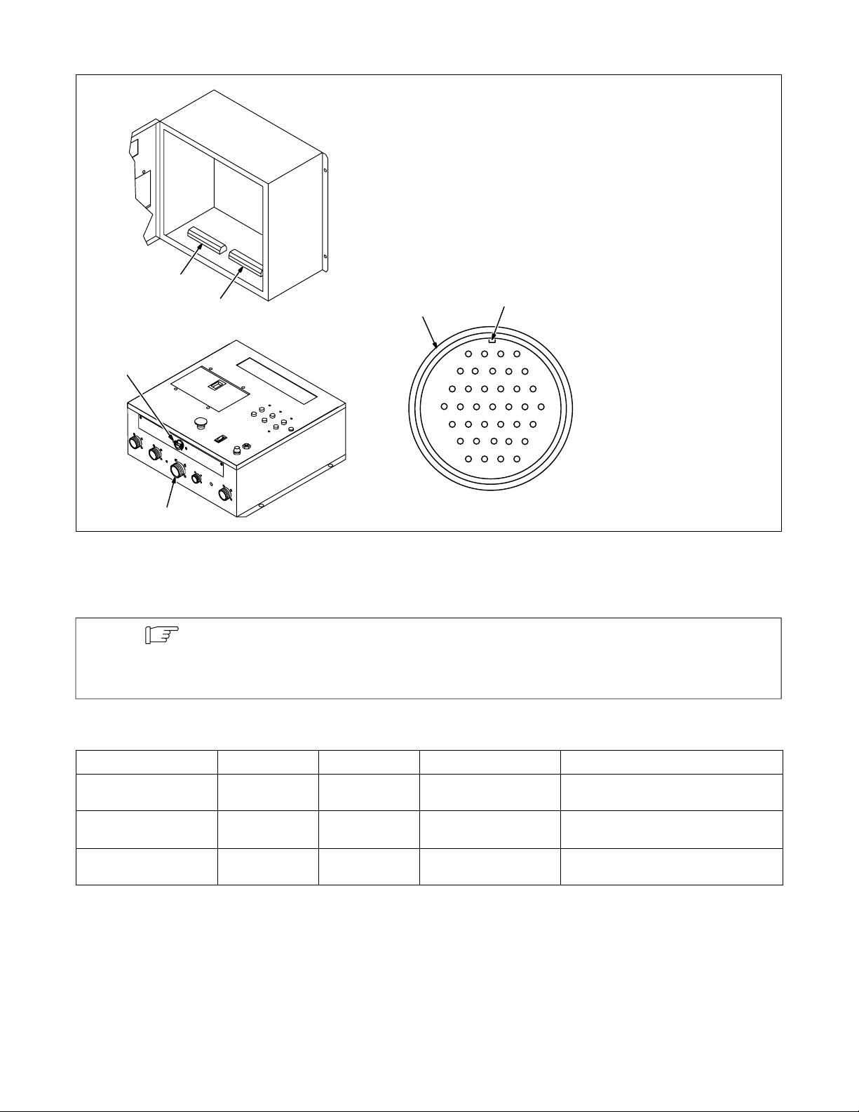
3-12. Input/Output Connections
2
1
3
5
K
S
6
BMCNLD
A
EGJFH
P
T
U V W X Z
cdbfae
gjmhk
pr sn
1 Terminal Strip 4T
2 Terminal Strip 5T
3 Optional Strain Relief (Part
No. 044 426)
Route customer-supplied cord from
external connections thru strain relief for lead connections to terminal
strips 4T and 5T.
4 Receptacle RC10
A customer supplied matching
amphenol plug (Part No.
MS3106A28-21P) is required for
connecting to receptacle RC10.
5 Plug
6 Keyway
R
4
Example Plug
Ref. ST-801 440
User I/O connections are provided at two locations on the unit, 37 socket receptacle RC10 on the outside of the bottom
panel and the terminal strip pair 4T and 5T on the inside of the bottom panel.
Note
Wiring for the terminal strip pair 4T – 5T and receptacle RC10 are parallel electrical connections.
The letter designations for receptacle sockets and terminal strip poles do not match. To
determine desired connections, see Sections 3-13, 3-14, 3-15, and 3-16 for lead identification
and matching terminal strip pole or receptacle socket.
3-13. Analog Designators*
Function Lead No. Socket No. Terminal Strip Pole Description
Analog Common 115 f 4T–G
Volts Feedback + 116 Z 4T–H
Current Feedback + 103 d 4T–E
*These outputs are analog signals from the unit and can source up to 100 mA per channel.
Common to any analog output signal from
the unit.
0 - 10 volt output signal (shows 0 - 100
volts).
0 - 10 volt output signal (shows 0 - 1000
arc amps).
OM-1595 Page 17
Page 24

3-14. Input Designators*
Function Lead No. Socket No. Terminal Strip Pole Description
Flow Switch 117 R 5T–T
When setup menu is enabled and a closure
is made, flow is detected for water or gas
monitoring (see Section 11-1).
Start Input 113 P 5T–S
Remote Program Select A 111 D 5T–R
Remote Program Select B 110 C 5T–P
Remote Program Select C 109 J 5T–N
Jog + 97 G 5T–E
Jog – 96 F 5T–D
Gas 98 E 5T–F
Common 99 N 5T–H All closure are in respect to this point.
Stop Input 102 X 5T–L
Remote Dec. Input 101 W 5T–K
Remote Inc. Input 100 V 5T–J
Error Reset 94 U 5T–B
When a closure is made, start signal is received (see Section 11-6).
When a closure is made, bit is active or on
(see Section 11-7).
When a closure is made, bit is active or on
(see Section 11-7).
When a closure is made, bit is active or on
(see Section 11-7).
When a closure is made, wire advances at
set jog speed (see Section 11-1).
When a closure is made, wire retracts at
set jog speed (see Section 11-1).
When a closure is made, gas solenoid will
open.
When a closure is made, program will go to
a stop condition.
When a closure is made, selected weld parameter will decrease.
When a closure is made, selected weld parameter will increase.
When a closure is made, most errors will
clear . Stop – Error Detected and Ground
Current Detect will need program stopped
or cycle power to clear respective error.
Test Weld 95 T 5T–C
Arc Enable 93 S 5T–A
Inc/Dec Selector 131 L 5T–U
Common 99 M 5T–H All closure are in respect to this point.
*These inputs are best described as pull to common type inputs. They typically are used with Common (common for discrete inputs) and either a set of
normally open relay contacts or a transistor. Electrically, whichever device is used to pull these inputs to Common must have a minimum rating of 24 V
DC and 15 mA. A closure should be maintained for a minimum of 50 milliseconds for the unit to detect the signal and any closure must be maintained for
the full time that the signal is required for the operation.
When a closure is made, unit will begin
welding without setting any outputs.
When a closure is made, status of arc
enable will change. A disabled arc unit will
only sequence through a weld program
only activating output devices.
Works with remote inc/dec. A closure
selects volts/trim parameter and an open
selects wire feed speed.
OM-1595 Page 18
Page 25
3-15. Output Designators*
Function Lead No. Socket No. Terminal Strip Pole Description
Output A (N.O.) 120 c 4T–J
Output A (N.O.) 121 b 4T–K
Output B (N.O.) 122 a 4T–L
Output B (N.O.) 123 g 4T–M
Error (N.O.) 124 m 4T–N
Error (N.O.) 125 k 4T–P
Arc Estab. (N.O.) 126 j 4T–R
Arc Estab. (N.O.) 127 h 4T–S
Arc Enable (N.O.) 104 e 4T–F
Arc Enable (N.O.) 135 B 5T–X
*These outputs are isolated relays with ratings of 0.6 A at 110 V DC or 2.0 A at 30 V DC. The output signal will settle within 30 milliseconds of the function
it is dedicated to starting. The two sides of the relay are indicated by the two listings in Section 3-15.
Two lines for isolated, programmable dry
contact output closure (see Sections 11-1
and 11-3).
Two lines for isolated, programmable dry
contact output closure (see Sections 11-1
and 11-3).
Two lines for isolated, dry contact output
Two lines for isolated, dry contact output
closure when unit is in an error condition.
Two lines for isolated, dry contact closure
to indicate state of welding arc. Closed
when arc is lit.
Two lines for isolated, dry contact closure
to indicate state of arc enable. Closed
when arc is enabled.
3-16. Special Input Designators*
Function Lead No. Socket No. Terminal Strip Pole Description
Provides a pair of leads to take the place of
Current Sense 12 n 4T–A
Current Sense 13 p 4T–B
E-Stop 14 r 4T–C
E-Stop 15 s 4T–D
*These inputs are isolated signals to the unit and not common to anything else. The input signal for the E-Stop function requires a set of normally closed
contacts so that when the contacts open, the unit goes into the Emergency Stop condition (jumper between terminals 3T–A and 3T–B must be removed
for external E-Stop to function [see circuit diagram]). The input signal rating is 35 V at 50 mA. Current Sense is only used with earlier model Deltaweld
welding power sources prior to the Deltaweld 452 and 652 models. Current Sense takes the place of Current Feedback from the weld as an input to the
weld control.
current feedback signals. Leads should be
shorted together when welding current is
present (closure from magnetic reed
switch). Typically used when welding
power source does not provide analog current feedback.
Provides for a remote Emergency Stop signal. When jumper is removed from
terminals 3T–A and 3T–B, these lines are
open causing unit go into an E-Stop
condition.
3-17. Installing Hub
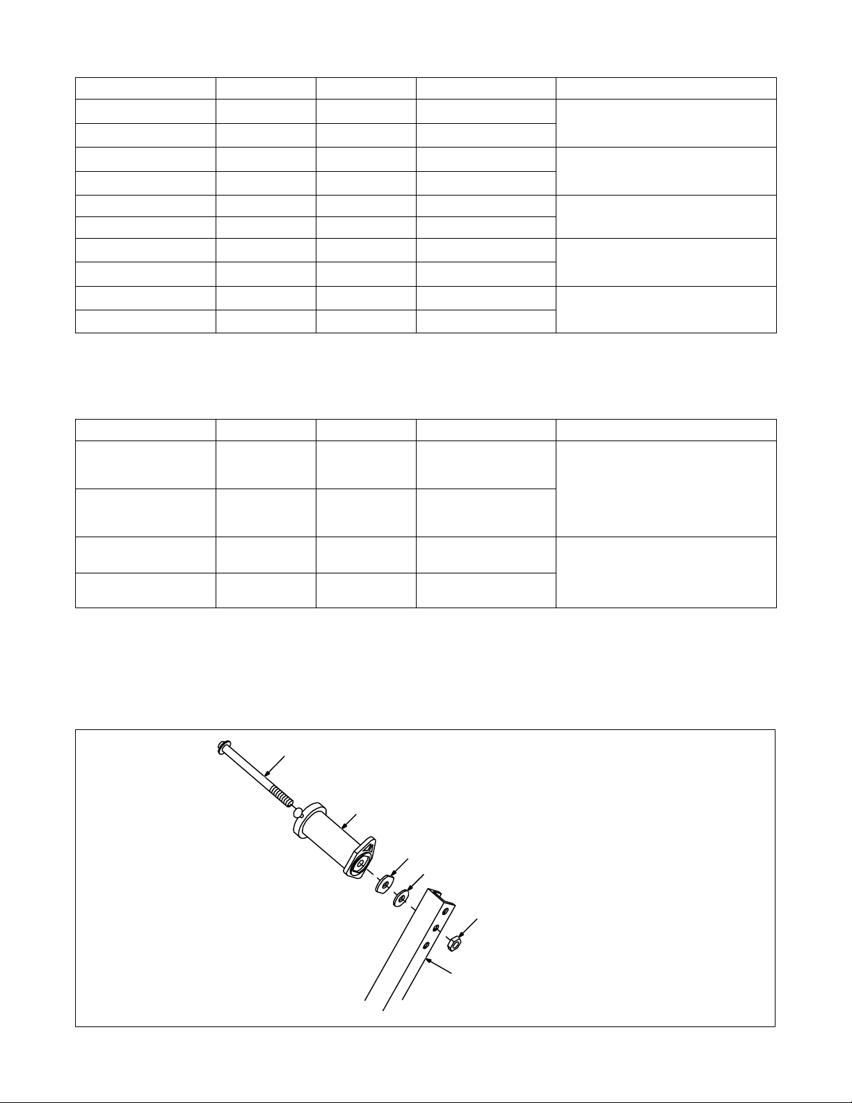
6
5
4
3
2
1
Spool support is typically installed
on top of side beam (see Section
3-1).
1 Spool S u p p o r t
Choose hole in support that allows
wire to enter drive assembly in the
straightest line.
2 Tension Adjustment Nut
3 Fiber Washer
4 Brake Washer
5 Hub Assembly
6 Hub Support Shaft
Remove nut from shaft. Install hub
assembly as shown.
ST-126 870-A
OM-1595 Page 19
Page 26
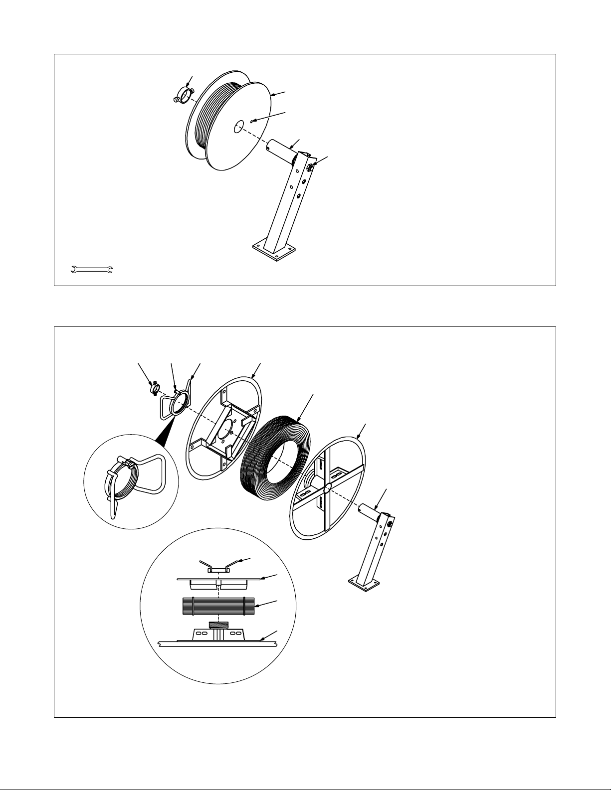
3-18. Installing Spool-Type Wire And Adjusting Hub Tension
1
Tools Needed:
9/16 in
3-19. Installing Optional Reel-Type Wire
134
Unlocked
2
1 Retaining Ring
2 Wire Spool
2
3
4
5
5
6
7
3 Hole In Spool
4 Hub
Remove retaining ring and slide
spool onto hub. Turn spool until hub
pin fits hole in spool. Reinstall retaining ring.
5 Tension Adjustment Nut
Grasp spool in one hand and turn
while using a wrench to adjust hex
nut. When a slight force is needed
to turn spool, tension is set.
ST-161 001
1 Retaining Ring
2 Lock
3 Spanner Nut
4 Wire Retainer
5 Welding Wire
6 Wire Reel
7 Hub
Remove retaining ring. Pull lock
and turn. Remove spanner nut, wire
retainer, and wire reel from hub.
To install wire lay wire reel on flat
surface and install wire as shown.
Tighten spanner nut until lock is in
position over hole in wire retainer.
Pull lock and turn to insert locking
pin into wire retainer.
Slide wire reel assembly onto hub.
Turn assembly until hub pin is
seated in hole in reel. Reinstall
retaining ring.
OM-1595 Page 20
3
4
5
6
Wire Installation
ST-161 000-A / ST-152 463 / Ref. ST-157 999-A
Page 27
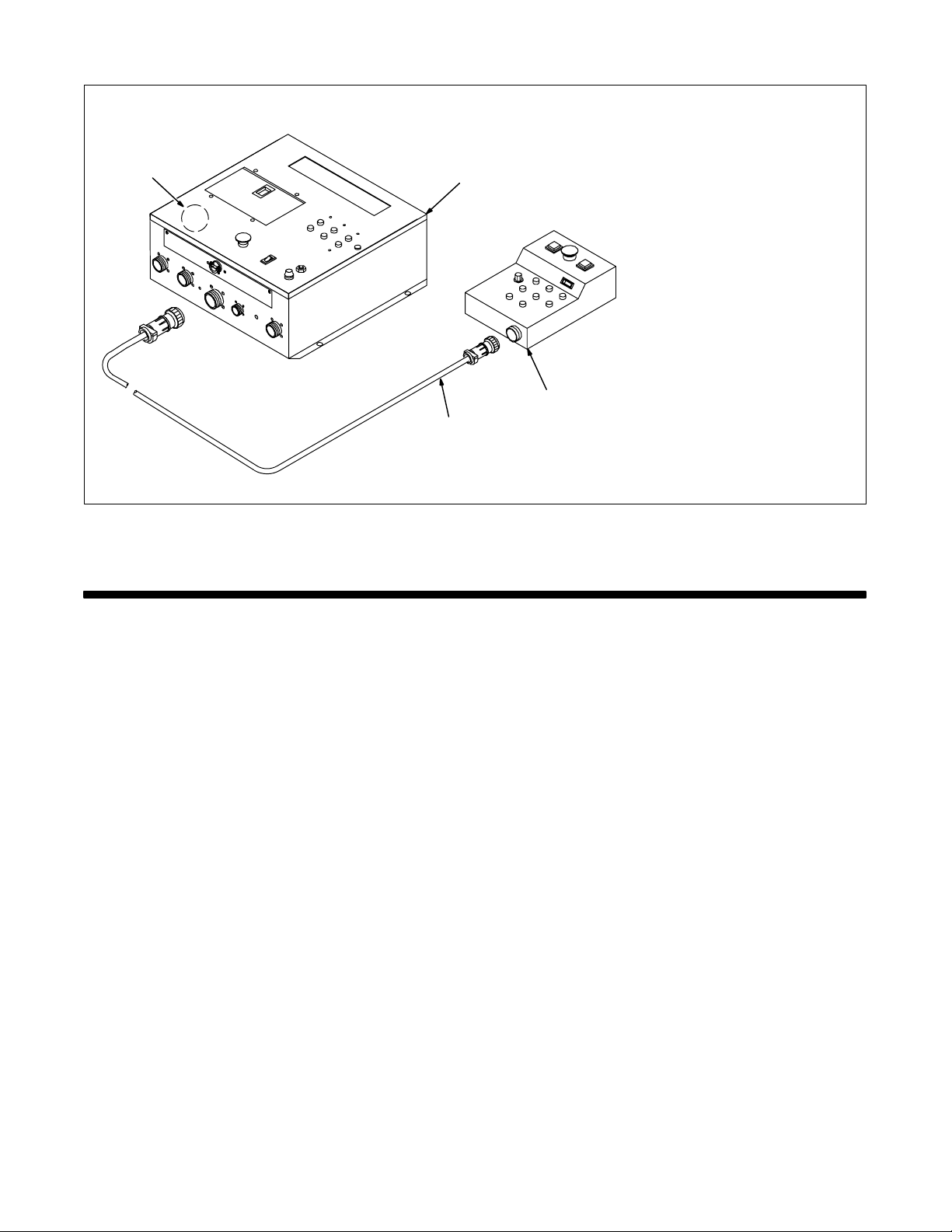
3-20. Connecting Optional Pendant To Microprocessor Weld Control
Turn Off welding power
source and weld control.
1 Microprocessor Weld Control
4
1
3
2
2 Interconnecting Cord
3 Pendant
To make connections, align
keyway, insert plug, and tighten
threaded collar.
4 Terminal Strip 3T Location
Remove emergency stop jumper
between 3 TA and 3TB.
Ref. ST-801 440 / ST-801 475
SECTION 4 – OPERATIONAL TERMS
The following is a list of terms and their definitions as they apply to this weld control:
General Terms:
Adaptive Pulse Welding When the “adaptive pulse” welding process is selected, the unit will automatically regulate pulse fre-
Abk (Background Amperage) Abk is the low weld current. Background current preheats welding wire and maintains the arc. When
Apk (Peak Amperage) Apk is the high pulse of welding current. Peak current melts the welding wire and forms a droplet. The
Inductance In short circuit GMAW welding, an increase in inductance will decrease the number of short circuit
Mig Welding This is standard Gas Metal Arc Welding (GMAW) where the weld control determines wire feed speed
PPS (Pulses Per Second) PPS, pulse rate, and frequency (Hz) are used interchangeably. A PPS or pulse rate of 60 Hz means
Pulse Welding The weld control controls the wire feed speed and pulse parameters (Peak Amperage, Background
PWms (Pulse Width in Milliseconds) PWms is the time spent at peak current (1.2 ms is .0012 seconds). This time must be long enough to
Trim Term used to represent arc length adjustments in pulse programs. Increasing trim increases the ac-
Synergic Synergic refers to the unit’s ability to use preprogrammed pulse parameters in order to determine the
quency in order to maintain a constant arc length, regardless of change in welding wire stickout.
background current is too low, the arc is unstable and hard to maintain.
droplet is forced into the weld puddle.
metal transfers per second (provided no other changes are made) and increase the arc-on time. The
increased arc-on time makes the pool more fluid.
and the welding power source controls arc voltage and inductance.
60 pulses of current are produced each second.
Amperage, Pulse Frequency and Pulse Width).
form a droplet of welding wire. The stiffness or fluidity of the molten weld puddle is controlled by
PWms.
tual arc length. Likewise, decreasing trim shortens arc length. Trim is replaced by volts in MIG programs.
actual pulse settings of Peak Amperage, Background Amperage, Pulse Frequency and Pulse Width
at any specific wire feed speed setting.
OM-1595 Page 21
Page 28

Note
Setup Panel Terms:
Card Mode Is used to select use of the optional data card storage and retrieval capabilities.
Process Mode Is used to select the type of process to be used, including Pulse, Adaptive Pulse, or Mig.
Sequence Mode Is used to select and program the weld sequences which include weld, crater, burnback, postflow,
Setup Screen Terms:
Access Code NOTE: The optional Data Card is required to activate this feature. With code off, access to the setup
See Menu Guide for detailed programming steps.
preflow, and run-in.
displays is not restricted. With code on, the operator must know and enter the access code to access
or change any of the setup displays.
To use code, press setup panel Parameter Select button to enter access code. When the correct
letter is entered, the indicator automatically moves to the next character. When the final access code
letter is entered, the display automatically changes to the initial setup display.
Arc Start NOTE: Do not use the Hot Start setting for .035 in (9 mm) or smaller wire. Use the Hot Start mode for
Arc Time Allows actual arc time up to 9,999.99 hours and weld cycles up to 999,999 to be accumulated and
Dual Schedule Is used to select the type of dual schedule switch that will be used when the dual schedule feature is
Mig Type (Voltage Correction) With DVC Voltage Correction On, the unit uses closed-loop feedback from the 14-pin cord or voltage
Name Card Programs When using the optional Data Card and turning the name feature on, customized programs written to
Program Reset By selecting program reset in the memory reset mode, the unit defaults to original factory program
Range The weld control requires that the voltage and amperage range of the welding power source be en-
Security NOTE: The optional Data Card is required to activate this feature. Is used to limit what the operator
Software (Version Number) When talking with service personnel, this number may be required. (Check actual unit display for
System NOTE: When Mig Only is selected, some setup choices are automatically made and are not available
System Reset By selecting system reset in the memory reset mode, the unit defaults to original factory settings for
Voltage (Control Feedback) Allows voltage to be monitored at the output terminals by two methods. This can be selected through
Arc Start/Volt Sense Shutdown When this feature is on, the system immediately shuts down if no arc voltage is sensed. An error
Wire Feed Allows the selection of inches per minute or meters per minute for wire feed speed. This mode is also
Burnback Method Allows the selection of either conventional burnback setting at arc end or wire retract at arc end.
Start Selection for type of start signal to begin a welding operation. Signal choice is either maintained
pulse welding with 450 Ampere Inverter Model when high initial weld current is necessary to start
large diameter welding wires. When in Hot Start, the 450 Ampere Inverter Model starts the arc in the
CV mode and switches to CC once the arc is started. Do not use Hot Start unless using 450 Ampere
Inverter Model.
displayed on the digital display, and can be reset to zero as required.
selected.
sensing leads to maintain set voltage parameters. With DVC Voltage Correction Of f, feedback from
the arc is not used for closed-loop feedback to maintain voltage parameters. Feedback from the arc is
still used for other functions.
Be sure voltage sensing leads are connected or voltage feedback is available through the 14-pin
receptacle via the welding power source.
the card can be identified by name, number, job number, etc.
settings for the program last active. All other program and setup information remains the same.
tered. Obtain this information from the welding power source Owner’s Manual.
can control. This includes accessing the number of the program, 1 through 8, and also the range of
welding parameters within the program selected.
number.) The factory keeps this number on file with the serial number of the unit.
for selection by the operator. This unit can be used either with a welding power source capable of
regular GMAW and pulse GMAW (Pulse/Mig) or a welding power source capable of GMA W (Mig
Only) welding only.
all programs and all set up excluding System, Arc Time, and Model T ype.
the 17-pin cord connection if the welding power source has a 17-pin receptacle, or through the use of
the unit’s external voltage sense lead.
If the 17 Pin setting is used, it is recommended that the voltage sensing terminals on the welding
power source be used to monitor arc voltage at the workpiece.
When using the V . Sense setting, arc voltage feedback is through the voltage sense leads connected
to the feeder. Use this setting when there is more than 50 ft (15 m) of weld cable used.
message is displayed. When this feature is off, wire feeds even when there is no arc voltage sensed.
used to select motor type; standard speed, low speed, or high speed. High speed motor is available
as factory option.
(maintained signal does not provide a time setting for a timed weld) or momentary (momentary starts
rely on either a time setting or a stop signal provided by the operator to end the welding operation).
OM-1595 Page 22
Page 29
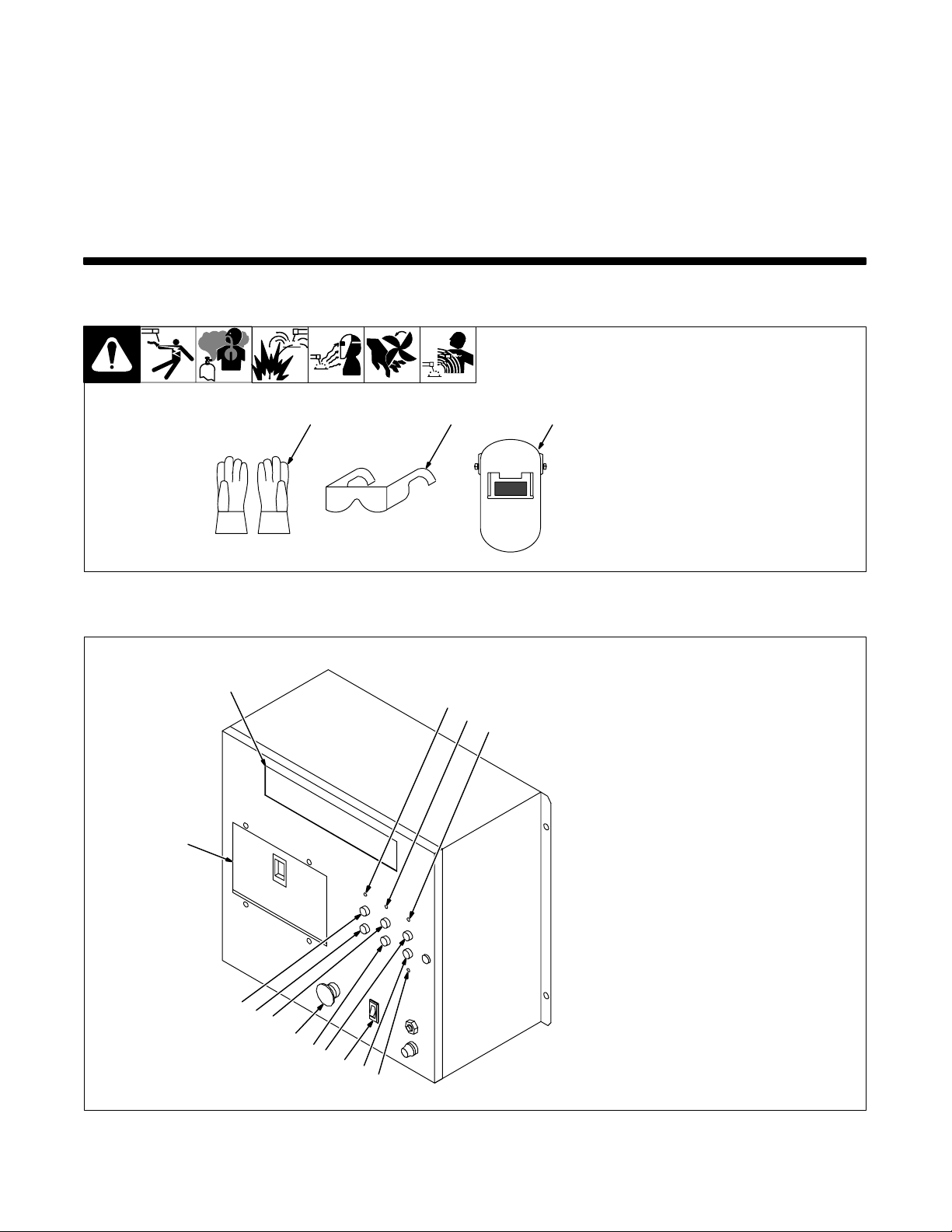
Polarity Check function for polarity at the welding arc. Turning this function on and setting a polarity causes
Output A Programmable output signal that activates at user predetermined times.
Output B Programmable output signal that activates at user predetermined times.
the software to rely on the user selection for the polarity at the welding arc. If polarity is incorrect, the
software generates an error condition (to allow this check function to operate properly, the shutdown
function must also be enabled, which the software does automatically after setting the polarity function). Voltage sensing leads must be connected properly for polarity checking to function in the correct
manner.
SECTION 5 – OPERATION
5-1. Safety Equipment
Wear the following while welding:
1 Dry, Insulating Gloves
2 Safety Glasses With Side
Shields
123
3 Welding Helmet With Correct
Shade Of Filter (See ANSI
Z49.1)
5-2. Front Panel Controls
1
14
13
12
11
10
9
sb3.1 1/94
1 Main Di s p l a y
2 Gas LED
2
3
4
8
7
6
5
3 Wire LED
4 Contactor LED
5 Weld Enable LED
6 Weld On/Off Push Button
7 Power Switch
8 Manual Weld Push Button
9 Wire Retract Push Button
10 Emergency Stop Button
11 Wire Advance Push Button
12 Error Reset Push Button
13 Purge Push Button
14 Setup Panel Door (See
Sections 5-10, 5-11, and 5-12)
Ref. ST-801 440
OM-1595 Page 23
Page 30
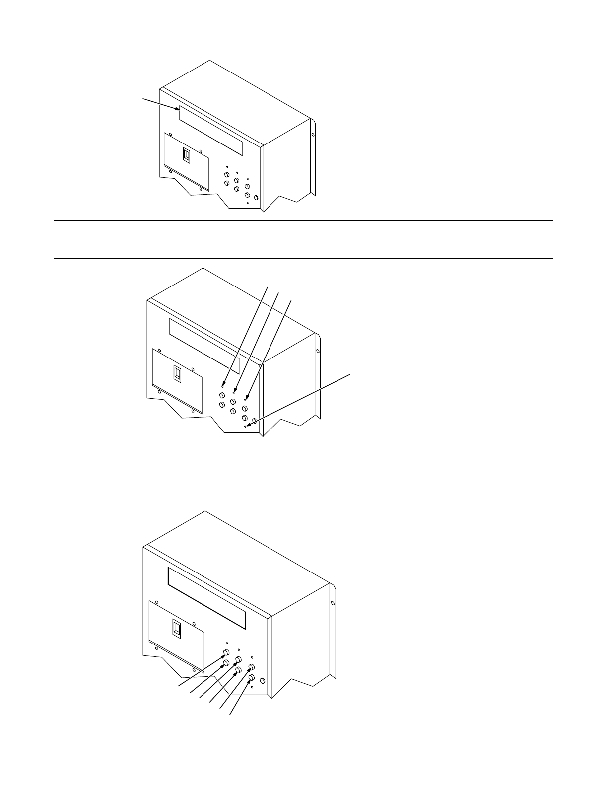
5-3. Main Display
1
5-4. Control LED’s
1 Main Di s p l a y
Shows system state, active
program, error messages, weld pa rameters at idle and during welding.
Ref. ST-801 440
1 Gas LED
1
2
3
4
LED lights when gas solenoid is energized.
2 Wire LED
LED lights when wire feed motor is
energized.
3 Contactor LED
LED lights when welding power
source contact o r i s e n e r g i z e d .
4 Weld Enable LED
LED lights whenever it is possible
to start the welding arc (see Section
5-8).
5-5. Control Push Buttons
1
2
3
4
Ref. ST-801 440
1 Purge Push Button
Momentarily energizes gas
solenoid to purge air from gun
shielding gas line, or to adjust
shielding gas regulator.
2 Error Reset Push Button
Resets the control after an error oc-
curs during operation.
3 Wire Advance Push Button
Advances wire out of the gun.
4 Wire Retract Push Button
Retracts wire up into the gun.
5 Manual Weld Push Button
Allows performing a welding
operation without energizing
peripheral interface outputs. (see
Section 5-9).
6 Weld On/Off Push Button
Enables o r disables the arc starting
ability of the weld control system
5
6
(see Section 5-8).
OM-1595 Page 24
Ref. ST-801 440
Page 31
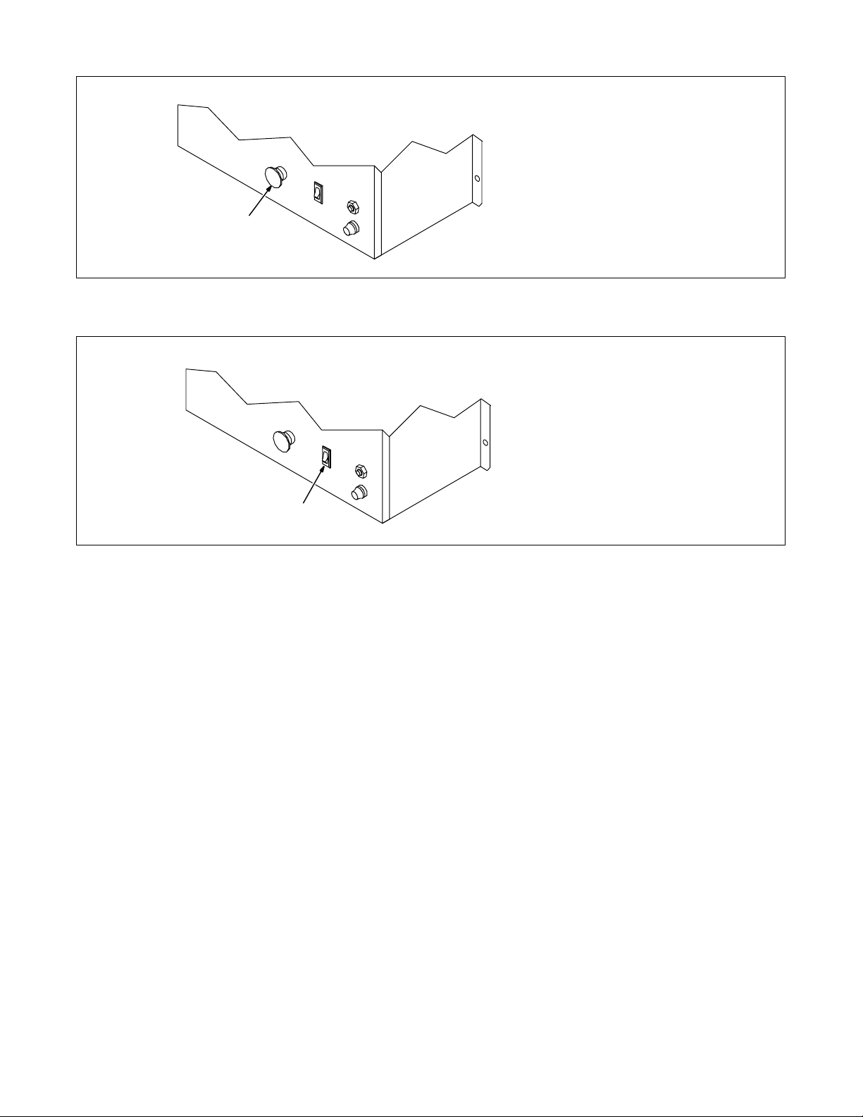
5-6. Emergency Stop Push Button
1
5-7. Power Switch
1 Emergency Stop Push Button
Stops control operation while a pro-
gram is running.
All weld control outputs go to the Off
state in an Emergency Stop condition.
Ref. ST-801 440
1 Power Switch
Use this switch to turn unit On and
Off.
1
Ref. ST-801 440
5-8. Weld Enable Button Or User I/O Weld Enable
The front panel Weld Enable button or user input Weld Enable allows disabling the arc starting ability of the weld control system. When the LED is off, a program can be run in automatic to check input/output logic without actually welding
during that sequence in a program.
5-9. Manual Weld Button Or User I/O Test Weld
The front panel Manual Weld button or user input Test Weld allows a welding sequence to be performed without the
input/output logic functioning for a program.
OM-1595 Page 25
Page 32
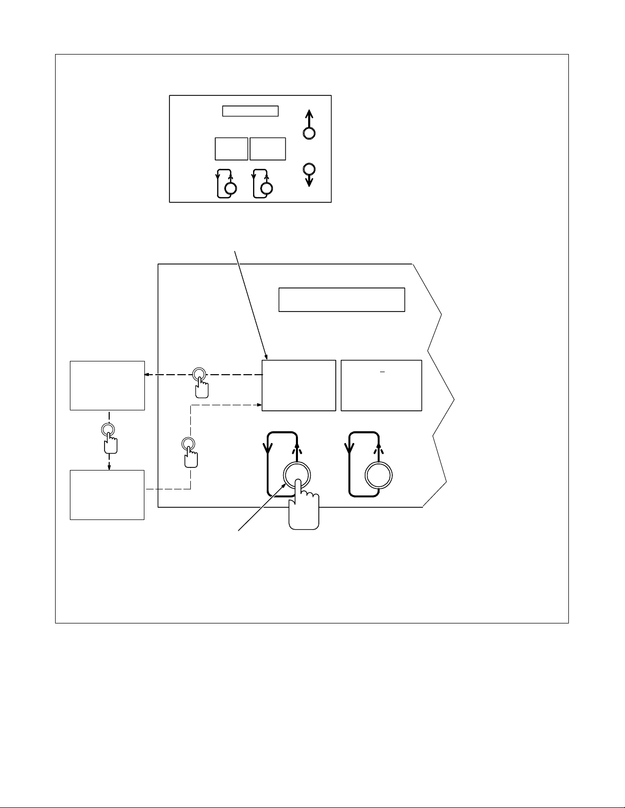
5-10. Mode Select Button
1 Mode Display
2 Mode Select Button
Press Mode Select button to move
indicator in left window display.
Go to Section 5-11.
Setup Panel
1
Process
>Sequence
Ca rd
Process
Sequence
>C a r d
>P r o c e s s
Sequence
Ca rd
2
Cycling Through Menu Options
>Prg 1
Pu l s e
03 5 ” Steel
Ar gon – Oxy
Ref. ST-154 109
OM-1595 Page 26
Page 33
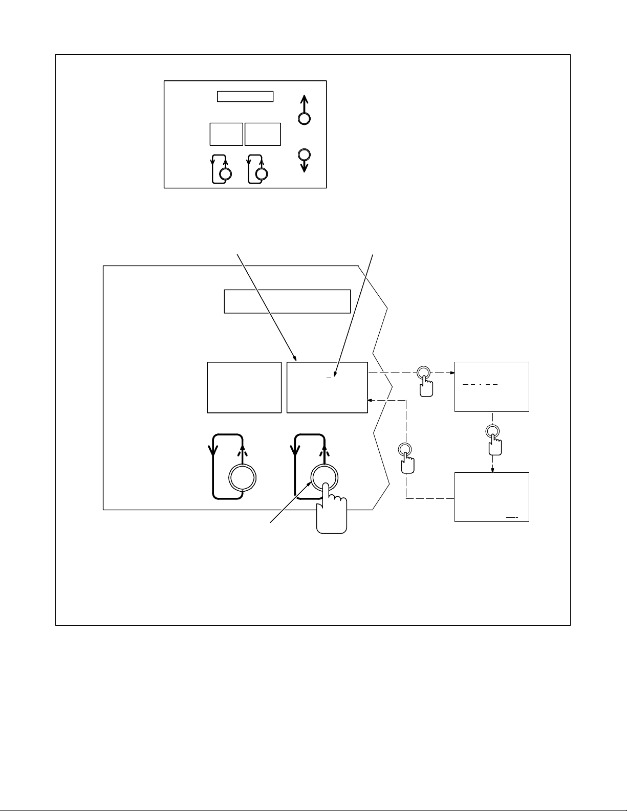
5-11. Parameter Select Button
Setup Panel
1 Parameter Display
2 Moving Line
Moving line is under value that can
be changed.
3 Parameter Select Button
Press parameter select button to
move indicator in right window
display.
Go to Section 5-12.
1
>P r o c e s s
Sequence
Ca rd
3
>Prg 1
Pu l s e
03 5 ” Steel
Ar g on – Oxy
2
Prg 1
>P u l s e
035” Steel
Argon – Oxy
Pu lse
035” Steel
Argon – Oxy
>T e a c h Off
Ref. ST-154 109
OM-1595 Page 27
Page 34
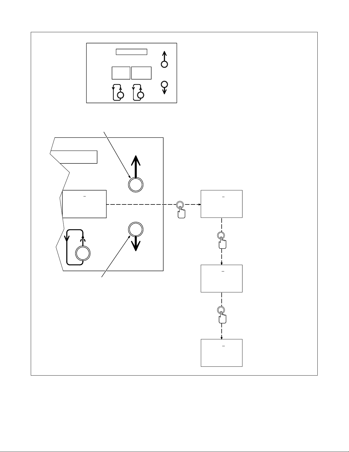
5-12. Parameter Increase And Decrease Buttons
Setup Panel
1
Use Mode Select button to select
mode to be changed (see Section
5-10).
Use parameter select button to
select parameter to be changed
(see Section 5-11).
1 Increase Button
Press button to increase value that
is underlined by the moving line.
2 Decrease Button
Press button to decrease value that
is underlined by the moving line.
>P r g 1
Pu lse
035” Steel
Argon– Oxy
>P r g 2
Pu lse
045” Steel
Argon – Oxy
Increase
Increase
>P r g 3
2
Pu lse
052” Steel
Argon – Oxy
Decrease
>P r g 2
Pu lse
045” Steel
Argon – Oxy
Ref. ST-154 109
OM-1595 Page 28
Page 35
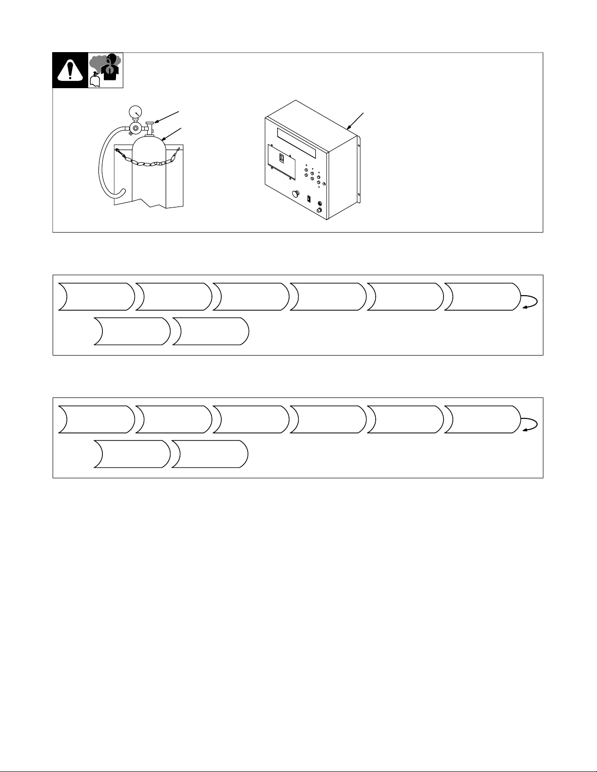
5-13. Shielding Gas
2
1
3
5-14. Sequence Of GMAW, GMAW-P, GMAW Spot, And FCAW
1 Shielding Gas Cylinder
2 Valve
3 Weld Control
Open valve on cylinder just before
welding.
Weld control turns weld output and
gas flow on and off.
Close valve on cylinder when
finished welding.
sb5.1* 5/94 – S-0621-C / ST-801 440
Install & Connect
Controller Into
Welding System
Adjust W eld
Parameters
As Needed
Put On
Personal Safety
Equipment
5-15. Sequence Of SAW
Install & Connect
Controller Into
Welding System
Adjust W eld
Parameters
As Needed
Install & Prepare
Flux System
Begin
Welding
Begin
Welding
Turn On
Welding System
Equipment
Put On Personal
Safety
Equipment
Turn On
Shielding Gas
If Applicable
Turn On
Welding System
Equipment
Set All Controls
And Verify
Program Selection
Set Controls All
And Verify
Program Selection
Perform Test
Weld
Perform Test
Weld
OM-1595 Page 29
Page 36
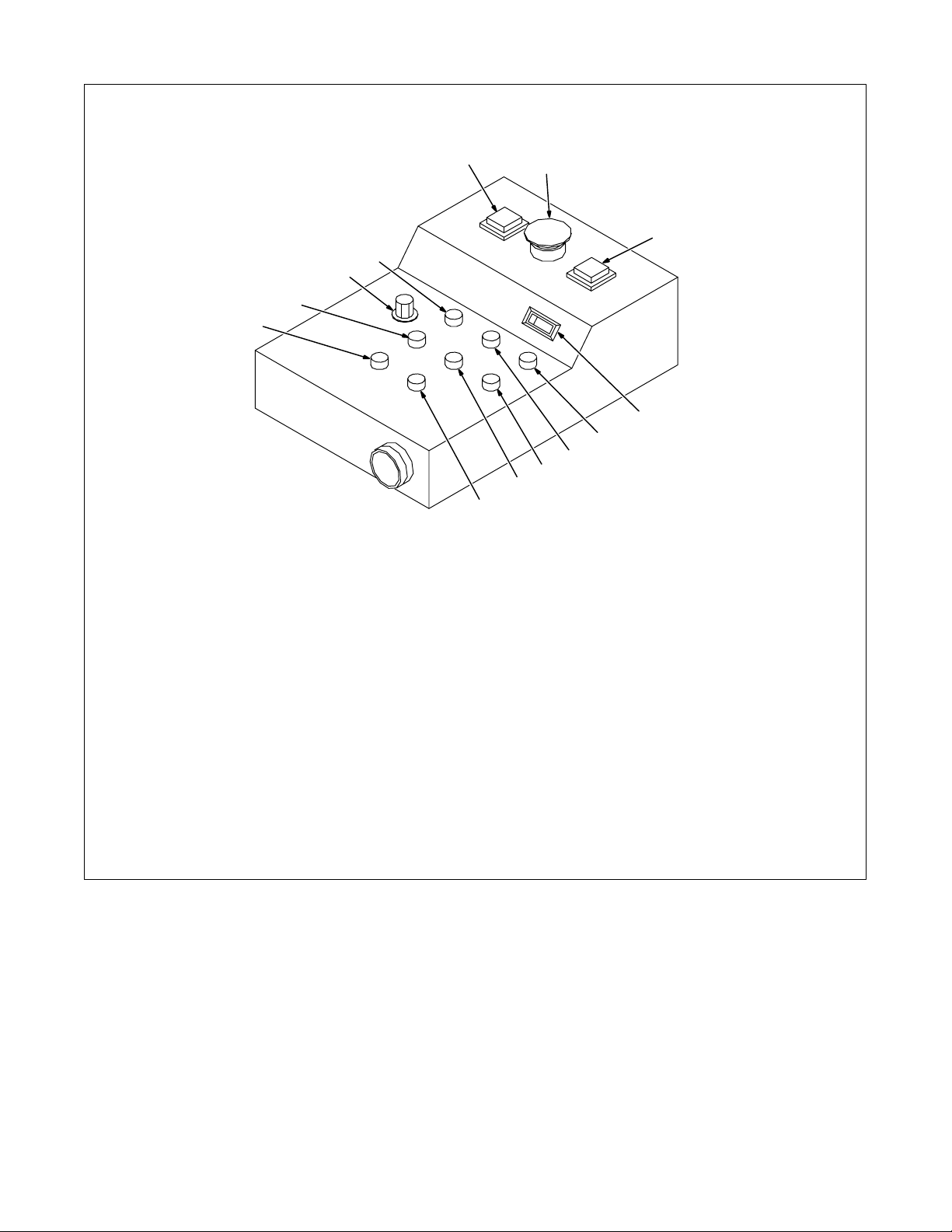
5-16. Optional Pendant Controls
11
10
1 Start Push Button
Starts weld program automatic operation.
2 Emergency Stop Push Button
Stops control operation while a program is
running.
All microprocessor weld control outputs go
to the Off state in an Emergency Stop condition.
3 Stop Push Button
Stops weld program automatic operation.
4 Selector Switch
Switch allows selecting either Wire Feed
Speed or Volts/Trim to appear on the displays. Switch works when unit is idle or during automatic operation.
1
13
12
8
9
5 Increase Push Button
Works with security feature on
microprocessor weld control to allow
increasing weld parameter values within the
allowable range.
6 Error Reset Push Button
Resets the co n t r o l after an error occurs dur-
ing operation.
7 Decrease Push Button
Works with security feature on
microprocessor weld control to allow
decreasing weld parameter values within the
allowable range.
8 Manual Weld Push Button
Allows performing a welding operation with-
out running a program.
2
3
4
5
6
7
ST-801 475
9 Wire Retract Push Button
Retracts wire up into the gun.
10 Wire Advance Push Button
Advances wire out of the gun.
11 Weld On/Off Push Button
Enables o r disables the arc starting ability of
the weld control system.
12 Program Select Switch
Rotate knob to select desired program
number for automatic operation.
13 Purge Push Button
Momentarily energizes gas solenoid to
purge air from gun shielding gas line or to adjust shielding gas regulator. Weld contactor
does not energize.
OM-1595 Page 30
Page 37
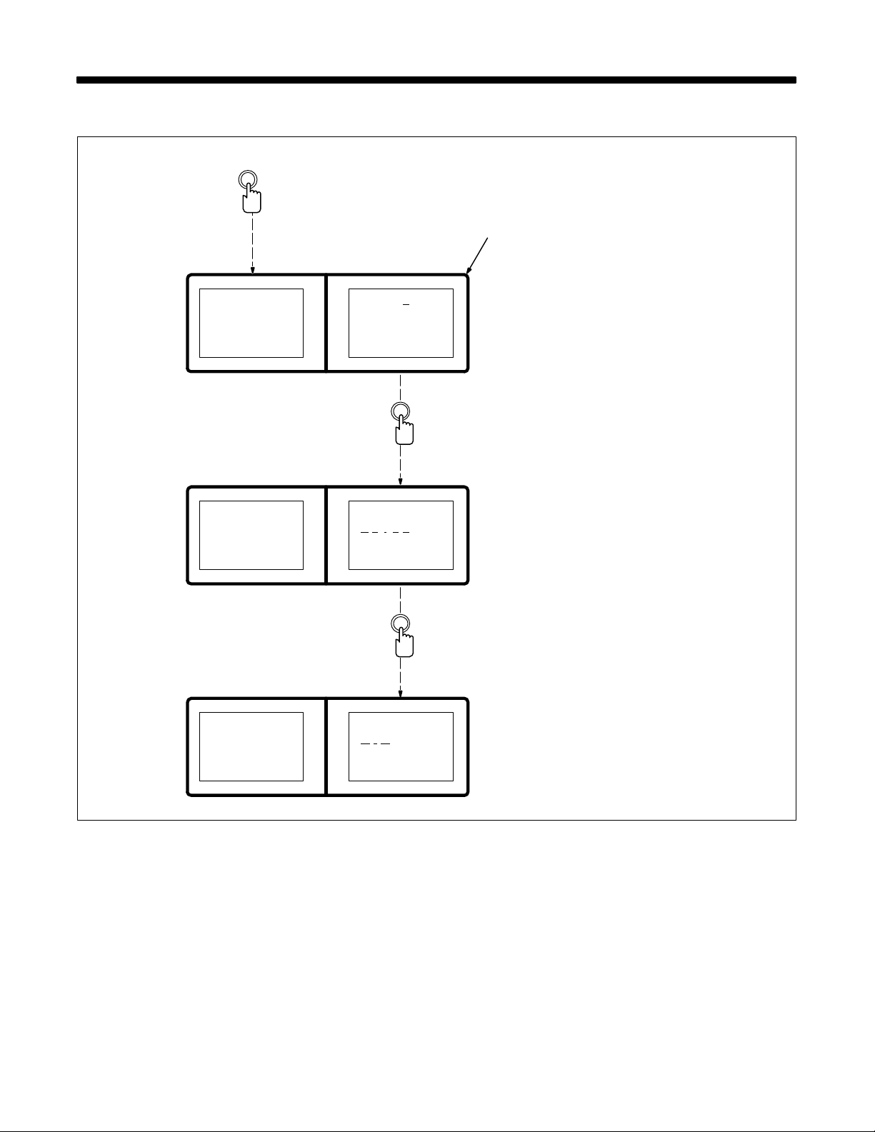
SECTION 6 – SETTING A MIG WELDING PROGRAM
6-1. Changing To Mig In The Process Mode
Mode Select
>P r o c e s s
Sequence
Ca rd
>P r g 1
Pu lse
035” Steel
Argon– Oxy
Parameter
Select
1 Setup Panel Display
Default display when unit is first
turned On, at other times use mode
select button to select Process.
The weld control is shipped factory
1
set for the MIG only process. To
change to the pulse process, use
the setup menu in the system mode
(see Section 11). When setup is in
the MIG only process, the system
cannot b e changed to the pulse process.
Go to Section 6-2.
>P r o c e s s
Sequence
Ca rd
>P r o c e s s
Sequence
Ca rd
Prg 1
>P u l s e
035” Steel
Argon– Oxy
Increase/
Decrease
Prg 1
>M I G
OM-1595 Page 31
Page 38
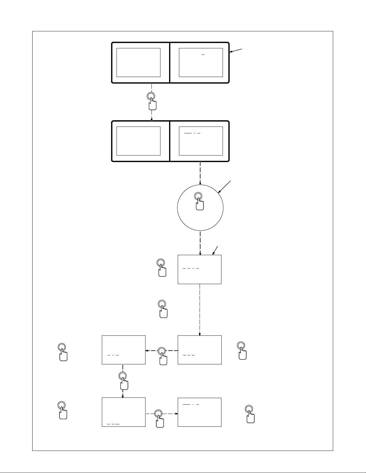
6-2. Setting Weld Sequence Display
>P r o c e s s
Sequence
Ca rd
Process
>Sequence
Ca rd
Mode
Select
>P r g 1
MIG
>We l d
18.0Vol t
200 IPM
0.0 Sec
1 Setup Panel Display
When unit is turned On, Process is
1
the default mode. Use mode select
button to select Sequence.
2 Setup Panel Parameter Select
Button
Use setup panel parameter select
button to select parameters.
3 Weld Parameters Display
Examples o f parameter ranges are
as follows:
Volts, 10.0-38.0 Volts
Wire Feed Speed, 50-780 Inches
Per Minute, IPM
Seconds, 0-25.0 Sec. (only for
momentary starting method). If
value set is zero (0), welding
continues until a stop signal is
received by the weld control.
Inductance, 0-99 %
Changes to voltage and wire feed
speed (IPM) parameters i n the weld
2
sequence are also displayed on th e
main display.
Go to Section 6-3.
Set Desired Weld Time,
If Applicable
Increase/
Decrease
Set Desired Inductance
If Applicable
Increase/
Decrease
We l d
420 IPM
>0 . 0 Sec
30%Induc
Parameter
Select
We l d
420 IPM
2.2 Sec
>3 0% Induc
Set Desired
Voltage
Increase/
Decrease
Parameter
Select
Parameter
Select
Parameter
Select
Parameter
Select
We l d
>1 8 . 0 Vol t
200 IPM
0.0 Sec
We l d
20.0Vol t
>2 0 0 IPM
0.0 Sec
>We l d
20.0Vol ts
420 IPM
2.2 Sec
3
Set Desired
Wire Feed
Speed
Increase/
Decrease
Increase
Proceed to next figure.
OM-1595 Page 32
Page 39
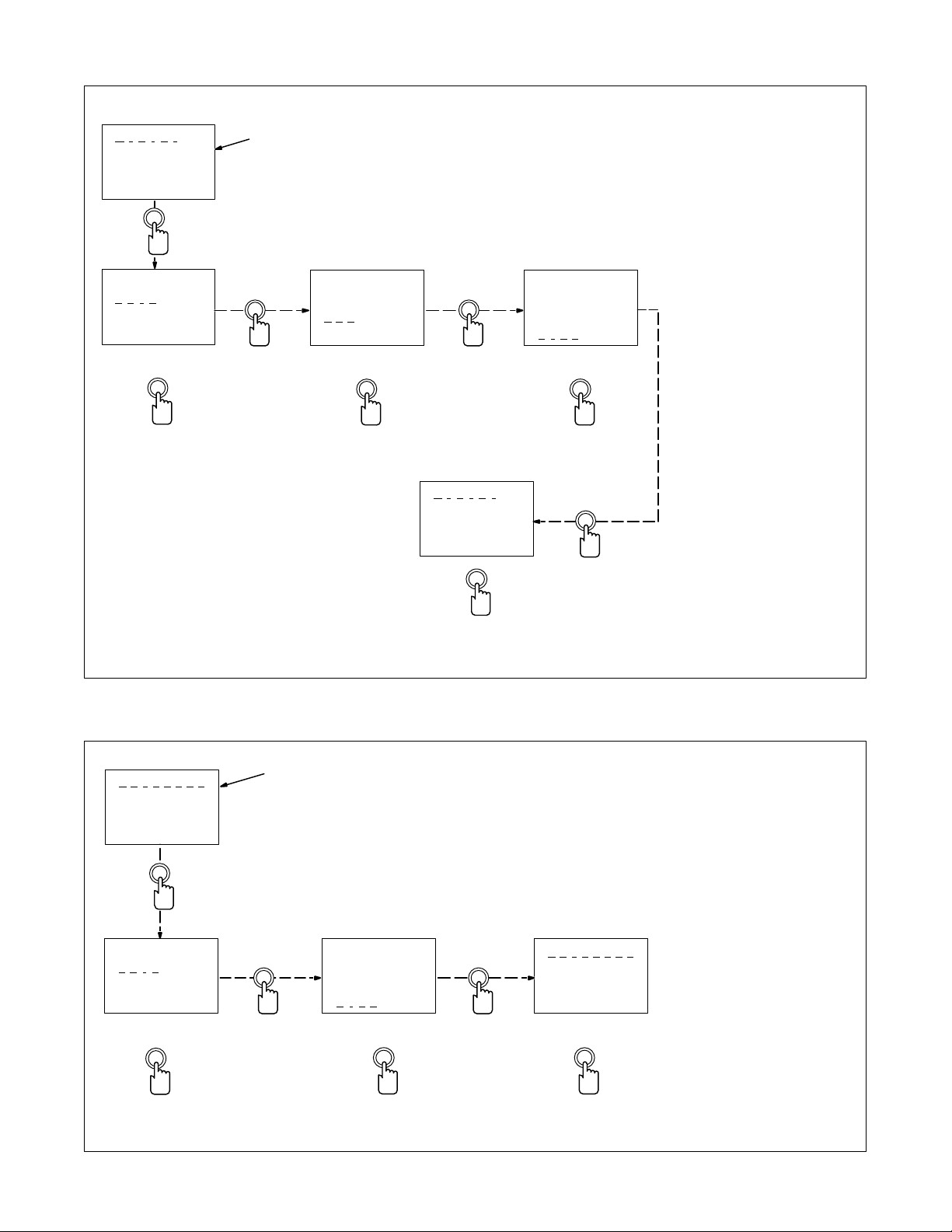
6-3. Setting Crater Sequence Display
>C r a t e r
18.0Vol t
200 IPM
0.00Sec
Parameter
Select
Crater
>1 8 . 0 Vol t
200 IPM
0.00Sec
Set Desired
Voltage
1
Parameter
Select
Crater
24.0Vol t
>2 0 0 IPM
0.00Sec
Set Desired
Wire Feed Speed
Parameter
Select
1 Crater Parameters Display
Examples o f parameter ranges are
as follows:
Volts, 10.0-38.0 Volts
Wire Feed Speed, 50-780 Inches
Per Minute, IPM
Seconds, 0-2.50 Sec. If value set is
zero (0), there is no Crater
sequence.
Go to Section 6-4.
Crater
24.0Vol t
400 IPM
>0 . 0 0 Sec
Set Desired Time
Increase/
Decrease
Increase/
Decrease
>C r a t e r
24.0Vol t
400 IPM
1.12Sec
Proceed to next figure.
6-4. Setting Burnback Sequence Display
>B u r n b a c k
18.0 Vol t
0.00 Sec
Parameter
Select
1
Increase/
Decrease
Parameter
Select
Increase
1 Burnback Parameters Display
Examples of parameter ranges are
as follows:
Volts, 10.0-38.0 Volts
Seconds, 0-0.25 seconds. If value
set is zero (0), there is no Burnback
sequence.
Go to Section 6-5.
Burnback
>1 6 . 0 Vo l t
0.00 Sec
Set Desired
Burnback Volts
Increase/
Decrease
Parameter
Select
Burnback
16.0 Vol t
>0 . 1 2 Sec
Set Desired Time
Increase/
Decrease
>B u r n b a c k
16.0 Vol t
0.12 Sec
Parameter
Select
Increase
Proceed to next figure.
OM-1595 Page 33
Page 40
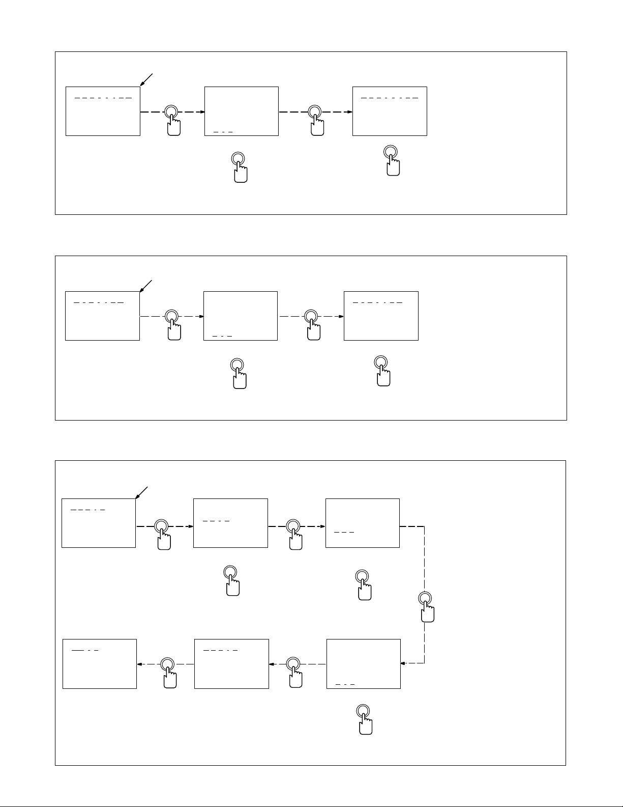
6-5. Setting Postflow Sequence Display
1
>P o s t f l o w
0.0 Sec
Parameter
Select
Pos t f low
>0 . 0 Sec
Set Desired Time
Increase/
Decrease
6-6. Setting Preflow Sequence Display
1
>P r e f l o w
0.0 Sec
Parameter
Select
Pref low
>0 . 0 Sec
Set Desired Time
Parameter
Select
Parameter
Select
>P o s t f l o w
1.2 Sec
Increase
Proceed to next figure.
>P r e f l o w
1.2 Sec
1 Postflow Parameters Display
Postflow can be adjusted from
0-9.9 seconds. If value set is zero
(0), there is no Postflow sequence.
Go to Section 6-6.
1 Preflow Parameters Display
Preflow can be adjusted from 0-9.9
seconds. If value set is zero (0),
there is no Preflow sequence.
Go to Section 6-7.
Increase/
Decrease
6-7. Setting Run-In Sequence Display
1
>R u n i n
18.0Vol t
200 IPM
0.0 Sec
Parameter
Select
>We l d
20.0Vol t
420 IPM
2.2 Sec
Increase
Run i n
>1 8 . 0 Vo l t
200 IPM
0.0 Sec
Set Desired V oltage
Increase/
Decrease
>R u n i n
20.0Vol t
150 IPM
0.5 Sec
Parameter
Select
Parameter
Select
Increase
Proceed to next figure.
Run i n
20.0Vol t
>2 0 0 IPM
0.0 Sec
Set Desired
Wire Feed Speed
Increase/
Decrease
Run i n
20.0Vol t
150 IPM
>0 . 5 Sec
Set Desired Time
1 Run-In Parameters Display
Examples o f parameter ranges are
as follows:
Volts, 10.0-38.0 Volts
Wire Feed Speed, 50-780 inches
per minute, IPM
Seconds, 0-2.5 Sec. If value set is
zero (0), there is no Run-In
sequence.
Parameter
Select
OM-1595 Page 34
Increase/
Decrease
Page 41
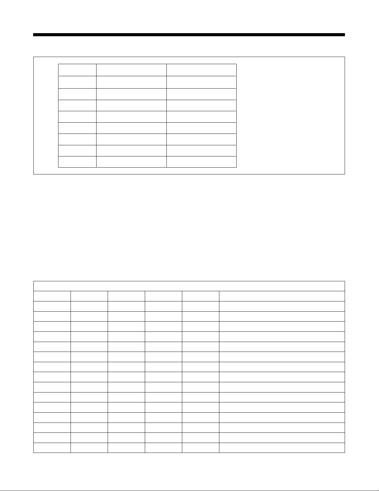
SECTION 7 – STANDARD PULSE WELDING PROGRAMS
7-1. Pulse MIG Programs
The eight pulse programs are
Program
1
2
3
4
5
6
Hardwire Selected*
.035” Steel, Argon – Oxy
.045” Steel, Argon – Oxy
.052” Steel, Argon – Oxy
.035” 309, Argon – CO2
.045” 309, Argon – CO2
3/64” 4043, Argon – CO2
Softwire Selected*
.045” 4043, Argon
.045” 5356, Argon
.035” 4043, Argon
.035” 5356, Argon
1/16” 4043, Argon
1/16” 5356, Argon
shown in the table. Each program
can be used in standard pulse MIG
or adaptive pulse MIG.
In an adaptive pulse MIG program,
the unit manipulates certain weld
variables to hold arc voltage
constant. This feature is described
in Section 9-5.
The factory-set parameters for
each program can be changed to
customize them for an application
(see Section 9).
7 3/64” 5356, Argon
8 .035” Nickel Alloy, Argon
.045” Steel, Argon – CO2
.045” Steel, Argon – Oxy
*Selecting hardwire or softwire
is done during setup (see
Section 11)
7-2. Standard Pulse Welding Programs
The following sixteen (16) pulse welding programs are in the control memory. Use this information if it is necessary to
change a standard program, or as a basis to build your own custom program. If at any time while changing a standard
program, or while building your own custom program, you want to go back to the standard program in the control
memory, see Section 11-5 for System memory Reset instructions. See Section 9 for explanation of Pulse welding
settings.
Apk = Peak Amperage, Abk = Background Amperage, PPS = Pulses Per Second, PWms = Pulse Width (milliseconds).
7-3. Program 1 – .035 ER 70S-3, Argon-Oxy
Wire Size/Type: .035” ER 70S-3 Gas: 98 Ar - 2 Oxy or 95Ar - 5 Oxy / 40 CFH
IPM / MPM Apk Abk PPS PWms COMMENTS
750 / 19.1 490 105 200 2.0
700 / 17.8 480 100 190 1.9
650 / 16.5 470 95 185 1.9
600 / 15.2 465 93 180 1.9
550 / 14.0 460 90 175 1.8
500 / 12.7 450 85 170 1.8
450 / 11.4 430 80 160 1.8
400 / 10.2 410 75 150 1.7
350 / 8.9 390 70 140 1.7
300 / 7.6 370 65 130 1.6
250 / 6.4 350 50 120 1.6
200 / 5.1 330 47 110 1.6
150 / 3.8 315 45 90 1.5
100 / 2.5 300 45 40 1.5
80 / 2.0 290 40 35 1.5
OM-1595 Page 35
Page 42
7-4. Program 2 – .045” ER 70S-3, Argon-Oxy
Wire Size/T ype: .045 ” ER 70S-3 Gas: 98Ar - 2 Oxy or 95 Ar - 5 Oxy / 40 CFH
IPM / MPM Apk Abk PPS PWms COMMENTS
750 / 19.1 540 110 220 3.2
700 / 17.8 530 110 210 3.2
650 / 16.5 520 110 200 3.2
600 / 15.2 510 110 190 3.2
550 / 14.0 500 110 180 3.1
500 / 12.7 490 105 170 3.0
450 / 11.4 470 105 160 2.9
400 / 10.2 450 100 150 2.8
350 / 8.9 440 100 140 2.7
300 / 7.6 430 95 130 2.6
250 / 6.4 420 90 120 2.5
200 / 5.1 400 80 100 2.5
150 / 3.8 380 70 80 2.4
100 / 2.5 345 50 60 2.4
80 / 2.0 310 30 38 2.2
7-5. Program 3 – .052 ER 70S-3, Argon-Oxy
Wire Size/T ype: .052 ” ER 70S-3 Gas: 98Ar - 2 Oxy or 95 Ar - 5 Oxy / 40 CFH
IPM / MPM Apk Abk PPS PWms COMMENTS
750 / 19.1 565 145 260 3.1
700 / 17.8 565 140 260 3.1
650 / 16.5 560 135 260 3.1
600 / 15.2 560 130 255 3.1
550 / 14.0 560 125 240 3.1
500 / 12.7 550 120 225 3.0
450 / 11.4 540 115 210 2.9
400 / 10.2 530 110 195 2.8
350 / 8.9 520 105 170 2.7
300 / 7.6 510 100 155 2.7
250 / 6.4 500 90 140 2.6
200 / 5.1 480 80 120 2.6
150 / 3.8 460 70 100 2.5
100 / 2.5 420 50 80 2.4
50 / 1.3 350 32 50 2.2
OM-1595 Page 36
Page 43
7-6. Program 4 – .035” ER 309, Argon - CO
2
Wire Size/Type: .035” ER 309Gas: 98 Ar - 2 CO2 or 95Ar - 5 CO
IPM / MPM Apk Abk PPS PWms COMMENTS
750 / 19.1 390 95 210 2.2
700 / 17.8 380 95 200 2.1
650 / 16.5 370 90 190 2.0
600 / 15.2 360 85 180 1.9
550 / 14.0 350 80 170 1.9
500 / 12.7 340 75 160 1.9
450 / 11.4 330 70 150 1.8
400 / 10.2 320 65 140 1.8
350 / 8.9 310 60 130 1.7
300 / 7.6 300 55 120 1.6
250 / 6.4 290 50 100 1.6
200 / 5.1 280 45 80 1.6
150 / 3.8 270 40 60 1.6
100 / 2.5 270 36 40 1.5
80 / 2.0 260 30 30 1.5
/ 40 CFH
2
7-7. Program 5 – .045” ER 309, Argon - CO
Wire Size/Type: .045” ER 309 Gas: 98 Ar - 2 CO2 or 95Ar - 5 CO2 / 40 CFH
IPM / MPM Apk Abk PPS PWms COMMENTS
750 / 19.1 490 115 290 2.3
700 / 17.8 480 115 280 2.3
650 / 16.5 450 115 270 2.1
600 / 15.2 435 112 260 2.0
550 / 14.0 430 110 240 2.0
500 / 12.7 425 105 230 1.9
450 / 11.4 420 105 220 1.9
400 / 10.2 415 105 200 1.8
350 / 8.9 410 100 180 1.8
300 / 7.6 400 95 160 1.7
250 / 6.4 380 88 140 1.7
200 / 5.1 360 85 115 1.7
150 / 3.8 340 68 88 1.6
100 / 2.5 320 50 70 1.6
80 / 2.0 310 45 60 1.5
2
OM-1595 Page 37
Page 44
7-8. Program 6 – 3/64” ER 4043, Argon
Wire Size/Type: 3/64” ER 4043 Gas: Argon / 40 CFH
IPM / MPM Apk Abk PPS PWms COMMENTS
750 / 19.1 510 150 190 3.5
700 / 17.8 485 150 180 3.4
650 / 16.5 485 150 180 3.4
600 / 15.2 470 145 180 3.3
550 / 14.0 445 140 170 3.1
500 / 12.7 420 135 160 2.9
450 / 11.4 400 130 150 2.8
400 / 10.2 360 120 140 2.7
350 / 8.9 340 115 130 2.6
300 / 7.6 310 100 120 2.5
250 / 6.4 277 87 110 2.4
200 / 5.1 250 68 100 2.3
150 / 3.8 215 50 90 2.1
100 / 2.5 190 30 80 2.0
80 / 2.0 190 27 45 2.0
7-9. Program 7 – 3/64” ER 5356, Argon
Wire Size/Type: 3/64” ER 5356 Gas: Argon / 40 CFH
IPM / MPM Apk Abk PPS PWms COMMENTS
750 / 19.1 515 130 190 2.8
700 / 17.8 510 120 190 2.8
650 / 16.5 490 120 180 2.7
600 / 15.2 470 115 170 2.7
550 / 14.0 450 110 160 2.6
500 / 12.7 430 100 150 2.5
450 / 11.4 410 90 140 2.5
400 / 10.2 390 80 130 2.4
350 / 8.9 370 65 112 2.4
300 / 7.6 340 52 103 2.3
250 / 6.4 325 47 90 2.3
200 / 5.1 300 40 80 2.2
150 / 3.8 277 35 53 2.2
100 / 2.5 260 24 40 2.2
50 / 1.3 230 20 35 2.0
OM-1595 Page 38
Page 45
7-10. Program 8 – .035” Nickel Alloy, Argon - He
Wire Size/T ype: .035 ” Nickel Alloy Gas: 75 Ar - 25 He / 40 CFH
IPM / MPM Apk Abk PPS PWms COMMENTS
750 / 19.1 390 110 130 3.5
700 / 17.8 380 105 130 3.5
650 / 16.5 370 100 125 3.4
600 / 15.2 360 90 120 3.4
550 / 14.0 350 85 115 3.3
500 / 12.7 345 80 110 3.3
450 / 11.4 340 75 105 3.3
400 / 10.2 335 65 90 3.2
350 / 8.9 332 60 75 3.1
300 / 7.6 320 55 65 3.0
250 / 6.4 310 50 58 3.0
200 / 5.1 297 44 52 2.9
150 / 3.8 282 37 42 2.9
100 / 2.5 262 29 33 2.8
50 / 1.3 225 23 30 2.7
Note
The next 8 programs are available after changing software wiretype (see Section 11-4).
7-11. Program 1 – .035” ER 4043, Argon
Wire Size/Type: .035” ER 4043 Gas: Argon / 40 CFH
IPM / MPM Apk Abk PPS PWms COMMENTS
750 / 19.1 450 140 155 2.0
730 / 18.5 445 135 150 1.9
720 / 18.3 440 130 145 1.9
710 / 18.0 430 130 140 1.8
655 / 16.6 415 120 135 1.7
600 / 15.2 400 118 125 1.7
545 / 13.8 395 115 115 1.6
490 / 12.4 370 100 105 1.5
435 / 11.0 350 90 100 1.4
380 / 9.7 320 78 95 1.3
325 / 8.3 285 72 80 1.2
270 / 6.9 265 60 75 1.1
215 / 5.5 245 48 70 1.1
160 / 4.1 205 41 49 1.0
140 / 3.6 200 38 46 1.0
OM-1595 Page 39
Page 46
7-12. Program 2 – 3/64” ER 4043, Argon
Wire Size/Type: 3/64” ER 4043 Gas: Argon / 40 CFH
IPM / MPM Apk Abk PPS PWms COMMENTS
750 / 19.1 530 170 270 3.0
740 / 18.8 515 168 265 3.0
720 / 18.3 500 160 260 2.9
710 / 18.0 480 155 252 2.8
655 / 16.6 450 150 245 2.7
600 / 15.2 420 143 240 2.6
545 / 13.8 396 135 235 2.5
490 / 12.4 372 128 230 2.4
435 / 11.0 350 120 225 2.3
380 / 9.7 325 114 205 2.2
325 / 8.3 295 105 187 2.1
270 / 6.9 275 87 160 2.0
215 / 5.5 243 71 152 1.9
160 / 4.1 212 55 125 1.9
105 / 2.7 210 41 55 1.9
7-13. Program 3 – 1/16” ER 4043, Argon
Wire Size/Type: 1/16” ER 4043 Gas: Argon / 40 CFH
IPM / MPM Apk Abk PPS PWms COMMENTS
770 / 19.6 560 251 294 2.7
730 / 18.5 560 251 294 2.7
710 / 18.0 560 251 294 2.7
655 / 16.6 560 251 294 2.7
600 / 15.2 558 251 290 2.7
545 / 13.8 540 251 275 2.6
490 / 12.4 520 251 250 2.5
435 / 11.0 495 251 225 2.4
380 / 9.7 470 251 190 2.2
325 / 8.3 455 240 150 2.0
270 / 6.9 420 218 112 1.8
215 / 5.5 380 168 90 1.7
160 / 4.1 340 115 80 1.6
105 / 2.7 295 73 55 1.5
70 / 1.8 290 45 50 1.5
OM-1595 Page 40
Page 47
7-14. Program 4 – .035” ER 5356, Argon
Wire Size/Type: .035” ER 5356 Gas: Argon / 40 CFH
IPM / MPM Apk Abk PPS PWms COMMENTS
760 / 19.1 300 118 140 3.6
740 / 18.8 295 114 145 3.5
720 / 18.3 290 110 140 3.4
710 / 18.0 286 103 128 3.3
655 / 16.6 276 95 124 3.2
600 / 15.2 268 86 115 3.2
545 / 13.8 250 80 107 3.1
490 / 12.4 238 78 105 3.0
435 / 11.0 230 73 100 2.9
380 / 9.7 215 65 90 2.8
325 / 8.3 195 63 80 2.7
270 / 6.9 180 58 70 2.5
215 / 5.5 178 45 56 2.4
160 / 4.1 175 33 45 2.3
105 / 2.7 175 25 29 2.2
7-15. Program 5 – 3/64” ER 5356, Argon
Wire Size/Type: 3/64” ER 5356 Gas: Argon / 40 CFH
IPM / MPM Apk Abk PPS PWms COMMENTS
755 / 19.2 465 138 270 3.0
730 / 18.5 445 130 265 2.9
700 / 17.8 425 128 255 2.8
680 / 17.3 405 120 245 2.7
655 / 16.6 385 110 235 2.6
600 / 15.2 365 100 228 2.5
545 / 13.8 345 92 215 2.5
490 / 12.4 330 85 200 2.4
435 / 11.0 320 80 193 2.3
380 / 9.7 310 78 186 2.2
325 / 8.3 300 75 158 2.1
270 / 6.9 272 65 130 2.0
215 / 5.5 245 53 110 1.9
160 / 4.1 236 47 67 1.8
105 / 2.7 231 22 62 1.8
OM-1595 Page 41
Page 48
7-16. Program 6 – 1/16” ER 5356, Argon
Wire Size/Type: 1/16” ER 5356 Gas: Argon / 40 CFH
IPM / MPM Apk Abk PPS PWms COMMENTS
770 / 19.6 560 251 294 2.7
735 / 18.7 560 251 294 2.7
710 / 18.0 560 251 294 2.7
655 / 16.6 545 251 294 2.7
600 / 15.2 515 251 270 2.6
545 / 13.8 480 251 224 2.5
490 / 12.4 447 251 175 2.3
435 / 11.0 427 240 155 2.1
380 / 9.7 407 220 140 2.0
325 / 8.3 387 190 126 1.9
270 / 6.9 367 160 112 1.8
215 / 5.5 354 124 92 1.7
160 / 4.1 328 95 68 1.6
105 / 2.7 315 51 58 1.6
75 / 1.9 311 35 58 1.5
7-17. Program 7 – 3/64” ER 5356, Argon
Wire Size/Type: 3/64” ER 5356 Gas: Argon / 40 CFH
IPM / MPM Apk Abk PPS PWms COMMENTS
750 / 19.1 465 138 270 3.0
720 / 18.3 445 130 265 2.9
700 / 17.8 425 125 255 2.8
680 / 17.3 402 120 244 2.7
655 / 16.6 382 110 235 2.6
600 / 15.2 360 99 225 2.5
545 / 13.8 340 92 215 2.5
490 / 12.4 325 85 200 2.4
435 / 11.0 315 80 177 2.3
380 / 9.7 305 76 168 2.2
325 / 8.3 290 60 145 2.1
270 / 6.9 270 55 125 2.0
215 / 5.5 247 50 100 1.9
160 / 4.1 225 41 68 1.8
105 / 2.7 225 19 58 1.8
OM-1595 Page 42
Page 49

7-18. Program 8 – .035” ER 5356, Argon
Wire Size/Type: .035” ER 5356 Gas: Argon / 40 CFH
IPM / MPM Apk Abk PPS PWms COMMENTS
770 / 19.6 300 120 150 3.6
740 / 18.8 295 114 145 3.5
720 / 18.3 290 110 140 3.4
710 / 18.0 286 103 133 3.3
655 / 16.6 275 93 124 3.2
600 / 15.2 267 85 117 3.2
545 / 13.8 250 80 107 3.1
490 / 12.4 235 78 100 3.0
435 / 11.0 222 71 90 2.9
380 / 9.7 207 65 83 2.8
325 / 8.3 190 64 72 2.6
270 / 6.9 185 52 65 2.4
215 / 5.5 182 40 58 2.2
160 / 4.1 180 30 43 2.1
105 / 2.7 180 23 30 2.0
OM-1595 Page 43
Page 50
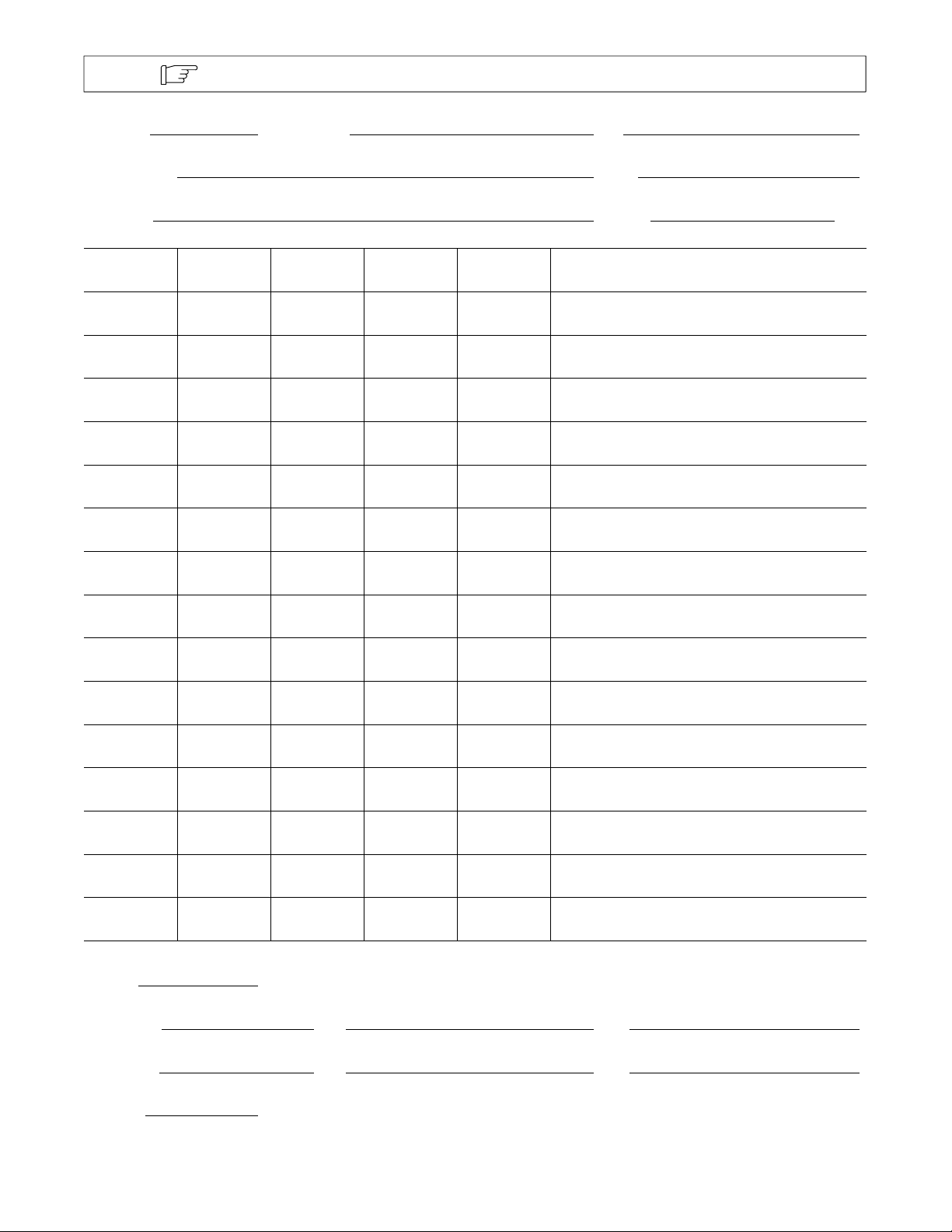
Note
Program # Wire Size/Type Gas
Program Name Card #
Gun Model Flowrate CFH
IPM ApK AbK PPS PWms COMMENTS
Make copies of this chart for future use.
Preflow: Sec.
Run-In Trim: IPM: Sec.:
Crater Trim: IPM: Sec.:
Postflow: Sec.
OM-1595 Page 44
Page 51
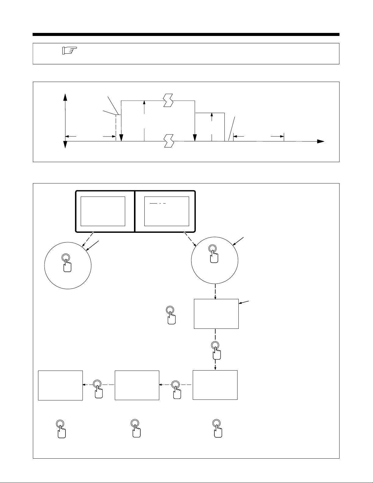
SECTION 8 – SETTING STANDARD PULSE WELDING PROGRAMS
Note
Section 8-1 is a graphic layout of a weld cycle. Follow examples in Sections 8-2 through 8-7 to
adjust sequence welding parameters to do weld.
8-1. Weld Cycle
Wire
Speed
Trigger
Pressed
Run-In Time
0-2.5 Sec.
Run-In
Speed
Preflow Time
0-9.9 Sec
Arc
Start
Weld Time 0-25 Sec.
Weld
Speed
8-2. Setting Weld Sequence Display
Process
>Sequence
Ca rd
1
Mode Select
>We l d
50. Tr im
200 IPM
0.0 Sec
Set Desired Weld
Sequence Voltage
Increase/
Decrease
Crater Time
0-2.5 Sec.
Trigger
Released
Parameter
We l d
>5 0 T r i m
200 IPM
0.0 Sec
Crater
Speed
Select
Burnback Time
0-0.25 Sec.
Arc
Out
Parameter
Select
Postflow Time
0-9.9 Sec.
1 Mode Select Button
When unit is turned On, Process is
the default mode, at other times,
use mode select button to select
Sequence.
2 Parameter Select Button
Use parameter select button to
select parameters.
2
3 Weld Parameters Display
Parameter ranges are as follows:
Trim (Arc Length), 0-99
Changes to Weld Sequence Trim
are also displayed on front panel
display.
Wire Feed Speed, 50-780 Inches
Per Minute, IPM
Changes to Weld Sequence IPM
3
are also displayed on front panel
display.
Seconds, 0-25.0 Sec. (only for
momentary starting method). If
value set is zero (0), welding will
continue until a stop signal is
received by the weld control.
Go to Section 8-3.
Time
Ref. S-0271
We l d
60 Tr im
300 IPM
>3 . 5 S e c
Increase
Proceed to next figure.
Parameter
Select
We l d
60 Tr im
300 IPM
>0 . 0 S e c
Set Desired Weld Sequence
Time, If Applicable
Increase/
Decrease
Parameter
Select
We l d
60 Tr im
>200 IPM
0.0 Sec
Set Desired Weld Sequence
Wire Feed Speed
Increase/
Decrease
OM-1595 Page 45
Page 52
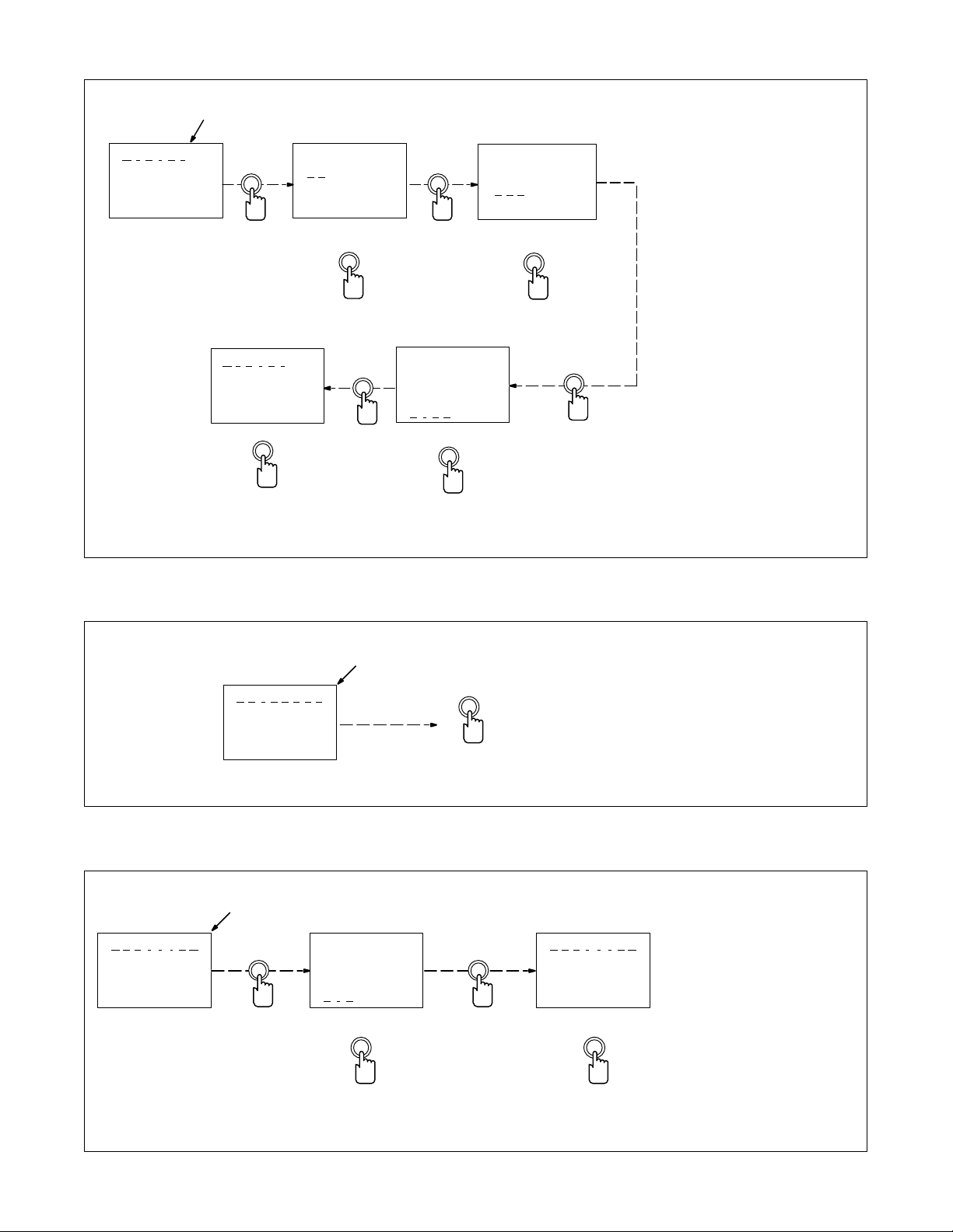
8-3. Setting Crater Sequence Display
>C r a t e r
50 Tr im
200 IPM
0.00 Sec
1
Crater
>5 0 Trim
200 IPM
0.00 Sec
Parameter
Select
>C r a t e r
60 Tr im
150 IPM
0.20 Sec
Increase
Proceed to next figure.
Set Desired
Trim
Increase/
Decrease
Parameter
Select
Parameter
Select
Crater
60 Tr im
150 IPM
>0 . 0 0 Sec
Set Desired Time
Increase/
Decrease
Crater
60 Tr im
>2 0 0 IPM
0.00 Sec
Set Desired
Wire Feed Speed
Increase/
Decrease
Parameter
Select
1 Crater Parameters Display
Examples o f parameter ranges are
as follows:
Trim (Arc Length), 0-99
Wire Feed Speed, 50-780 Inches
Per Minute, IPM
Seconds, 0-2.50 Sec. If value set is
zero (0), there is no Crater
sequence.
Go to Section 8-4.
8-4. Setting Burnback Sequence Display
1
>B u r n b a c k
0.00 Sec
Proceed to next figure.
8-5. Setting Postflow Sequence Display
1
>P o s t f l o w
0.0 Sec
Parameter
Select
Pos t f low
>0 . 0 Sec
Set Desired Time
Increase
Parameter
Select
>P o s t f l o w
1.2 Sec
1 Burnback Parameters Display
Burnback is n o t functional in Pulse,
set time to zero (0).
Go to Section 8-5.
1 Postflow Parameters Display
Postflow can be adjusted from
0-9.9 seconds. If value set is zero
(0), there is no Postflow sequence.
Go to Section 8-6.
OM-1595 Page 46
Increase/
Decrease
Increase
Proceed to next figure.
Page 53
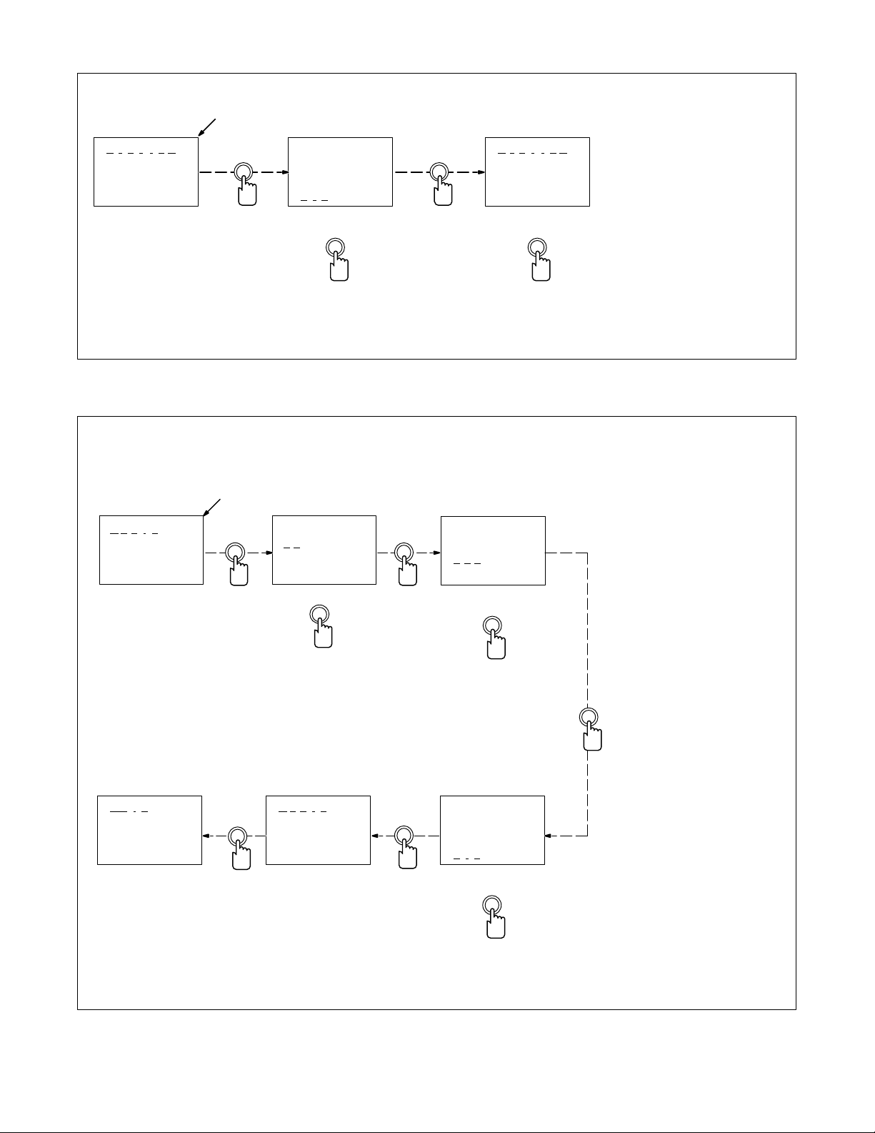
8-6. Setting Preflow Sequence Display
1
>P r e f l o w
Pref low
r e f l o w
>P
1 Preflow Parameters Display
Preflow can be adjusted from 0-9.9
seconds. If value set is zero (0),
there is no Preflow sequence.
Go to Section 8-7.
0.0 Sec
Parameter
Select
>0 . 0 Sec
Set Desired Time
Increase/
Decrease Proceed to next figure.
8-7. Setting Run-In Sequence Display
1
>R u n i n
50. Tr im
200 IPM
0.0 Sec
Parameter
Select
Run i n
>5 0 Trim
200 IPM
0.0 Sec
Set Desired Trim
Parameter
Select
Parameter
Select
Run i n
55 Tr im
>2 0 0 IPM
0.0 Sec
Set Desired
Wire Feed Speed
1.2 Sec
Increase
1 Run-In Parameters Display
Examples o f parameter ranges are
as follows:
Trim, 0-99.
Wire Feed Speed, 50-780 inches
per minute, IPM
Seconds, 0-2.5 Sec. If value set is
zero (0), there is no Run-In
sequence.
>We l d
60 Tr im
300 IPM
3.5 Sec
Increase
Increase/
Decrease
>R u n i n
55 Tr im
150 IPM
1.1 Sec
Parameter
Select
Increase/
Decrease
Run i n
55 Tr im
150 IPM
>0 . 0 Sec
Set Desired Time
Increase/
Decrease
Parameter
Select
OM-1595 Page 47
Page 54
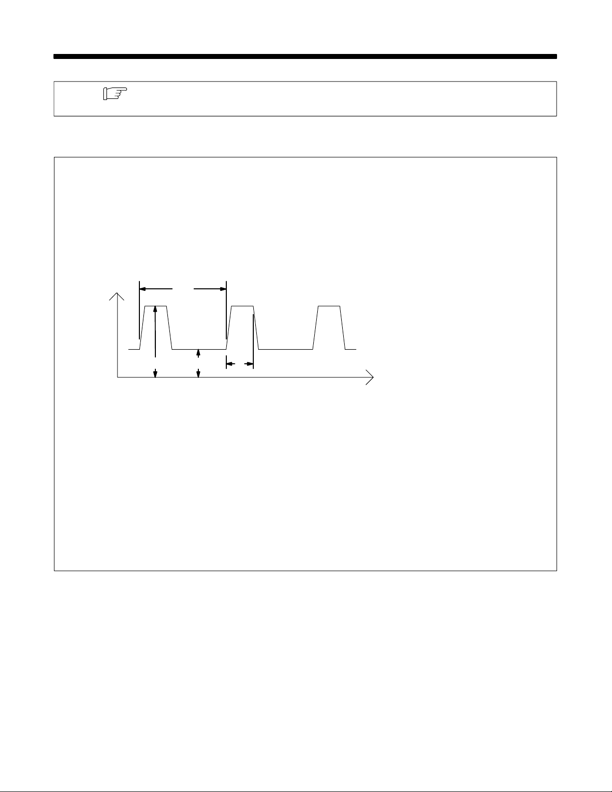
SECTION 9 – TEACHING A PULSE WELDING PROGRAM
Note
See GMAW-P (Pulsed MIG) Process Guide (MILLER Part No. 158 920) supplied with unit for
more information.
9-1. Pulse Waveforms And Explanation Of Terms
3
Amps (Current)
2 41
Time
The weld control, not the welding
power source, controls weld output
for pulsed welds.
1 ApK – Peak Current Of
100-565 Amperes
ApK is the high pulse of welding
current. Peak current melts the
welding wire and forms a droplet.
The droplet is forced into the weld
puddle.
2 AbK – Background Current Of
10-200 Amperes
AbK is the low weld current. Background current preheats welding
wire and maintains the arc. When
background current is too low, the
arc is unstable and hard to
maintain.
3 PPS – Pulses Per Second Of
20-400
PPS, pulse rate, and frequency
(Hz) are used interchangeably. A
PPS or pulse rate of 60 Hz means
60 pulses of current are produced
each second.
4 PWms – Pulse Width Of
1.0-5.0 Milliseconds
PWms is the time spent at peak current (1.2 ms is .0012 seconds). This
time must be long enough to form a
droplet of welding wire. The stiffness or fluidity of the molten weld
puddle is controlled by PWms.
OM-1595 Page 48
Ref. S-0259
Page 55
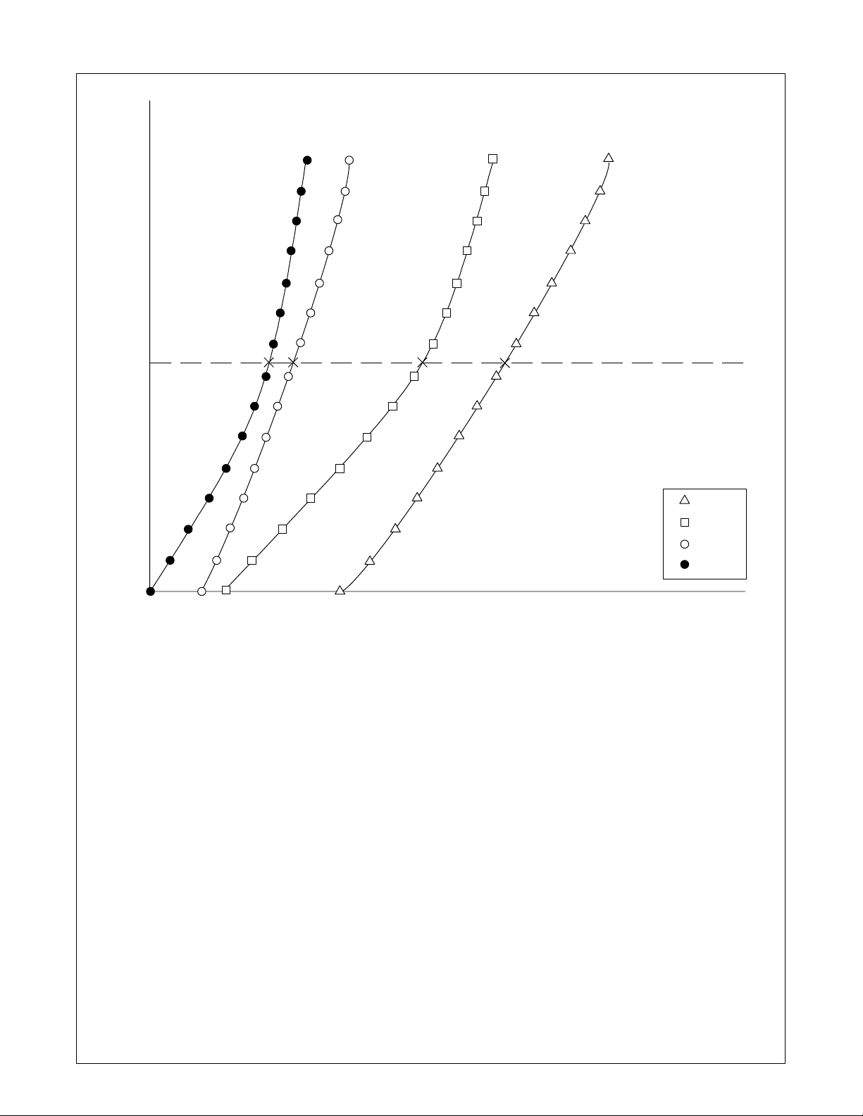
9-2. Typical Teach Point Settings And Resulting Synergic Setting
IPM
780
750
700
650
600
550
500
450
400
350
300
250
200
150
100
50
100 180 210 240 270 300 330 360 370 420 450 480 510 540 565 ApK
10 20 30 40 50 60 70 80 90 100 110 120 130 140 200 AbK
20 55 80 105 130 160 185 210 235 260 290 315 340 365 400 PPS
1 3 5 PWms24
Example Of A Synergic
Setting For 425 IPM With
All Teach Points Set At
50 IPM Increments
ApK
AbK
PPS
PWms
The teach mode allows the user to create
custom pulse MIG welding programs. The
teach mode has 15 teach points. At each
teach point, the user can adjust four
parameters: peak amperage (ApK), background amperage (AbK), pulses per second
(PPS), and pulse width in milliseconds
(PWms) to shape the pulse waveform of the
weld output.
Wire feed speed teach points can range from
the minimum to the maximum wire feed
speed of the wire drive assembly. When using a standard speed motor, wire feed speed
teach points typically range from 50 to 750
ipm. The wire feed speed of a teach point can
be redefined in increments of 50 ipm between adjacent teach points (see Section
9-3). The weld control uses pulse parameters at teach points to establish the pulse parameters at any wire feed speed setting.
Below the wire feed speed of the lowest
teach point, and above the wire feed speed
of the highest teach point, the unit may limit
wire feed speed settings in pulse MIG to
maintain all pulse parameters within the
capability o f the unit.
Pulse MIG programs made by the
manufacturer have pulse waveform
information entered for all 15 teach points.
The operator can relocate and modify the
setting o f one, or any number of the 15 teach
points if the factory set information is not appropriate for a specific application.
After the parameters for each teach point are
established, an arc must be struck and
maintained for at least 2 seconds. This allows the weld control to learn the arc length
associated with the taught pulse parame-
ters. To ensure a proper arc length reading,
electrode stick-out must be carefully
maintained, and the weld must be terminated
by pressing a stop button, not by moving the
welding gun away from the workpiece.
The taught arc length represents a Trim (arc
length) setting of 50. Increasing the value of
Trim, increases the actual arc length.
Likewise, decreasing the value of Trim will
decrease actual arc length.
In the Pulse mode, the unit does not maintain
a constant arc length with variations in electrode stick-out. In the Adaptive Pulse mode,
the unit adjusts pulse frequency to maintain
a constant arc length regardless of variations in electrode stick-out.
Proceed to next figure to teach a pulse MIG
program.
OM-1595 Page 49
Page 56
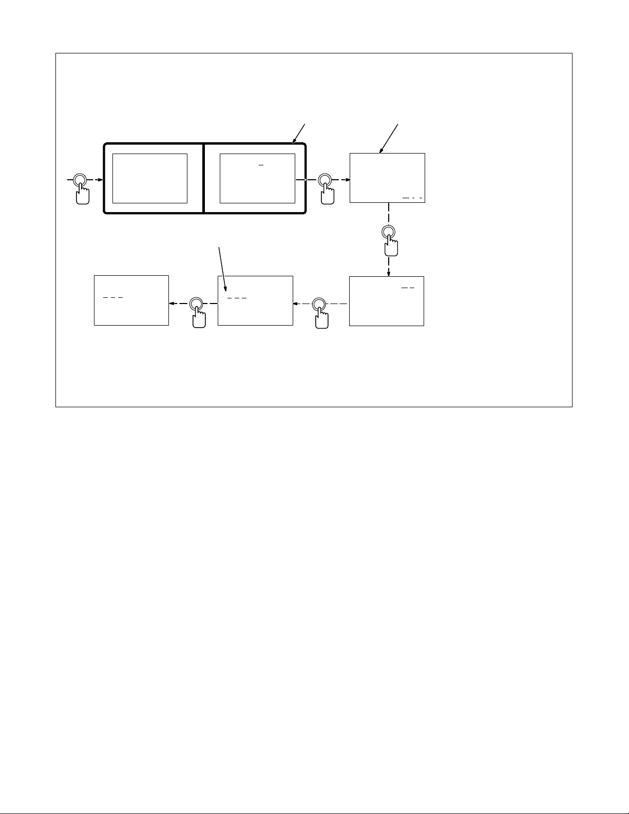
9-3. Selecting And/Or Redefining Teach Point Wire Feed Speed
Selecting A Teach Point
Mode
Select
>P r o c e s s
Sequence
Ca rd
>P r g 1
Pu lse
035” Steel
1
Parameter
Select
Pu lse
035” Steel
>T e a c h O f f
2
1 Process Display
When unit is first turned On,
Process is the default screen, at
other times use mode select button
to select Process.
2 Teach Display
Use parameter select button to
select Teach.
Use increase/decrease buttons to
select On.
3 IPM (Teach Point)
Select a teach point with the
parameter select button.
Use increase/decrease buttons to
change IPM (teach point).
Teach On
>4 5 0 IPM
340 ApK
70 AbK
Increase/
Decrease
3
Teach On
>4 0 0 IPM
340 Apk
70 Abk
Parameter
Select
Increase/
Decrease
>T e a c h On
400 IPM
340 Apk
70 Abk
OM-1595 Page 50
Page 57
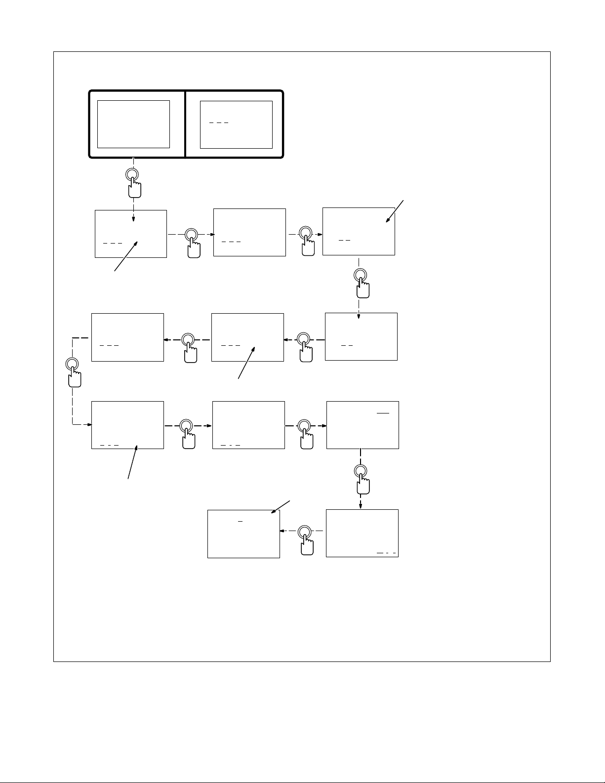
9-4. Setting Teach Point Parameters On The Setup Panel
>P r o c e s s
Sequence
Ca rd
Parameter
Select
Teach On
460 IPM
>3 4 0 Apk
70 Abk
1
Increase/
Decrease
Teach On
>4 6 0 IPM
340 Apk
70 Abk
Teach On
460 IPM
>3 4 3 Apk
70 Abk
Parameter
Select
460 IPM
343 Apk
>70 Abk
160 PPS
Increase/
Decrease
When the Process Teach mode is
On, and one of the following pulse
parameters is selected: ApK, AbK,
PPS, or PWms, the value can be
changed as follows:
1 ApK Display
2 AbK Display
3 PPS Display
4 PWms Display
When values have been set for a
teach point, strike and maintain an
arc for five seconds. Repeat
procedure at each teach point until
custom program is complete (see
2
Section 9-2).
Turn Teach mode Off.
5 Custom Pulse Screen
The letter C will appear in the upper
right corner of all customized
programs.
To set Sequence Welding
Parameters, see Section 8.
343 Apk
92 Abk
>2 8 0 PPS
1.9 PWms
Parameter
Select
343 Apk
92 Abk
280 PPS
>1 . 9 PWm s
4
Increase/
Decrease
Increase/
Decrease
343 Apk
92 Abk
>1 6 0 PPS
1.9 PWms
3
343 Apk
92 Abk
280 PPS
>3 . 6 PWm s
Weld for
5 seconds
Prg1 C
Pu lse
035” Steel
Argon-Oxy
Parameter
Select
Parameter
Select
5
Parameter
Select
460 IPM
343 Apk
>92 Abk
160 PPS
>T e a c h O n
460 IPM
343 Apk
92 Abk
Increase/
Decrease
Pu lse
035” Steel
Argon-Oxy
>T e a c h O f f
OM-1595 Page 51
Page 58
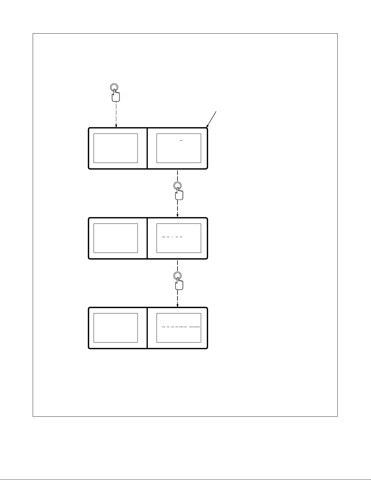
9-5. Changing To Adaptive Pulse Welding
Mode Select
Welding parameters are the same
for both a Pulse and an Adaptive
Pulse welding program. While
welding adaptively, the unit uses
feedback to attempt to maintain a
constant arc length. To change to
Adaptive Pulse welding, proceed
as shown:
1 Setup Panel Display
Default display when unit is first
turned On, at other times use mode
1
select button to select Process.
>P r o c e s s
Sequence
Ca rd
>P r o c e s s
Sequence
Ca rd
>P r g 1
Pu lse
035” Steel
Argon– Oxy
Parameter
Prg 1
>P u l s e
035” Steel
Argon– Oxy
Increase/
Decrease
Select
OM-1595 Page 52
>P r o c e s s
Sequence
Ca rd
Prg 1
>A d a ptPu lse
035” Steel
Argon– Oxy
Page 59
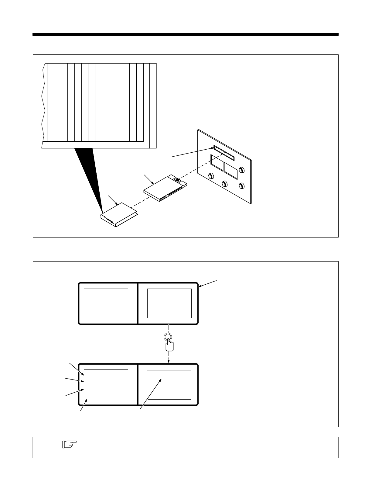
SECTION 10 – USING THE DATA CARD OPTION
10-1. Installing Data Card
14
11
7
8
9
4
5
6
60-M Data Card
1
1
2
3
THIS SIDE UP
3
2
10
12
13
1 Label
Peel backing from label and apply
to data card with THIS SIDE UP by
metal pins.
Write the names of the programs
stored on the card on the label.
Write the name of the piece of
equipment the card is used with on
the label.
2 Data Card
3 Card Slot
For Blank Data Card:
Insert card into slot. To format card,
turn On power to the unit. Select
Card from menu. Data card formats
when unit enters Card mode. Exit
Card mode and turn Off power.
For Power Source Data Card:
Insert card into slot. Turn weld
control On. Push Parameter Select
button within 3 seconds and the 8
programs and setup information is
read into the weld control memory.
Remove card when “Please Wait”
message disappears from front
panel display.
ST-156 266-B / Ref. S-155 823
10-2. Using The Data Card
Process
Sequence
>C a r d
2
3
4
>Wr i t e
Read
De l et e
Done
5
#1Pul se
035” Steel
Argon– Oxy
6
Press
Be low
Select Once
Press
Parameter
Use Mode Select button to select
Card.
1
1 Card Display
2 Write
Used to transfer program data from
unit to card. The program card can
hold up to 32 programs. When
writing to the card, the next
available program number is
automatically assigned.
3 Read
Used to transfer program data from
card to unit.
4 Delete
Used to delete program data from
card.
5 Done
Used to exit card display.
6 Moving Line
Moving line is under value that can
be changed.
Note
All process programs (Pulse, Adaptive Pulse, and MIG) can be stored on a data card and
retrieved.
OM-1595 Page 53
Page 60
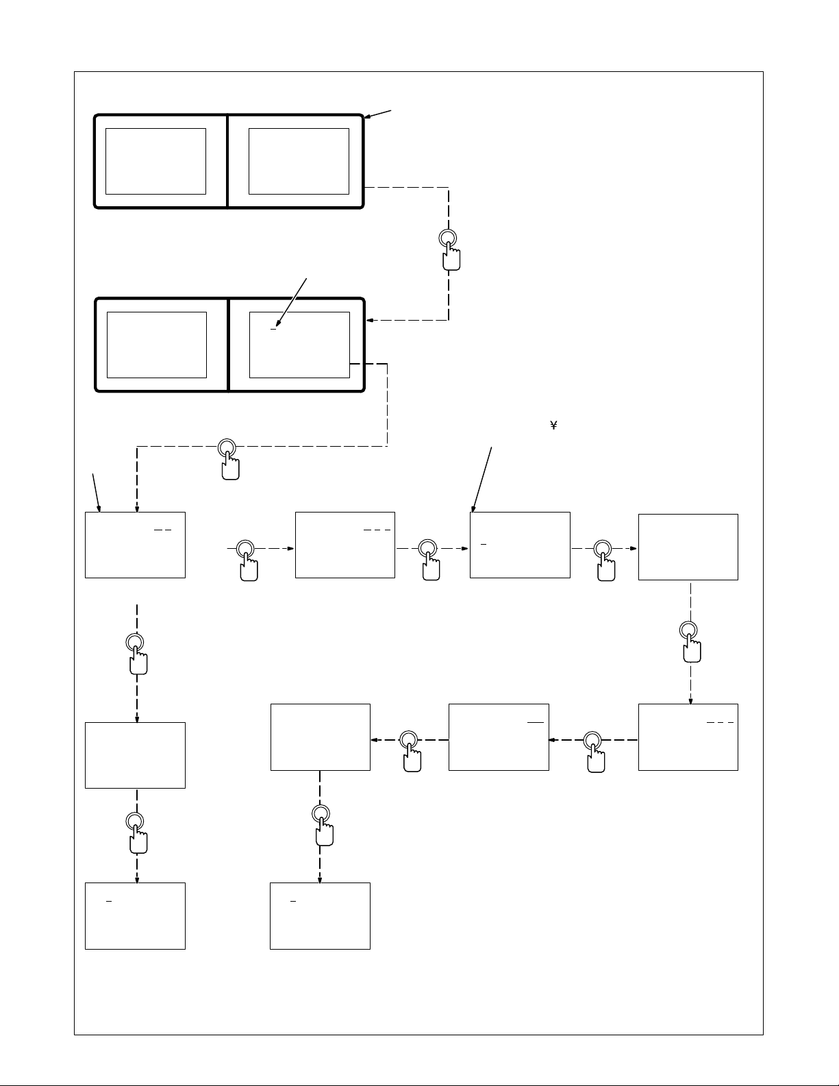
10-3. Naming Programs And Writing To Card
1
Process
Sequence
>C a r d P r e s s
Be low
2
Parameter
Select
1 Card Display
Use Mode Select button to select
Card.
2 Moving Line
Moving line is under value that can
be changed. Use increase or
decrease button to change value.
3 Name Display
If no name is desired, press setup
panel Parameter Select button to
continue the write procedure.
>Wr i t e
Read
De l et e
Done
3
Name? No
035” Steel
Argon– Oxy
Press
No
Parameter
Wr i teDone
Prg 1 to
Ca rdPr g 1
Press
Select
Parameter
Yes
Select
Increase
#1 Pu lse
035” Steel
Argon– Oxy
Press
Name? Ye s
035” Steel
Argon– Oxy
Press
Wr i teDone
Prg1 to
Ca rd Pr g1
Press
Parameter
Select
Parameter
Select
* = Allowable characters include: 0 thru 9, :, ;, <,
=, >, ?, @, A thru Z, [, , ], ^, _,‘, a thru z , blank , !,
”, #, $, %, &, ’, (, ), *, +, –, ., /,
Name? Yes
0 35” Steel
Argon– Oxy
⇒Press
Name? No
5007992
Frame
Press
Increase/
Decrease
Increase
Name? Yes
5007992
Frame _
⇒Press
Name? Ye s
5007992
Frame
Press
Parameter
Select
#1 Pu lse
035” Steel
Argon– Oxy
Press
OM-1595 Page 54
Parameter
Select
Parameter
#1 Pu lse
5007992
Frame
Press
Select
Page 61
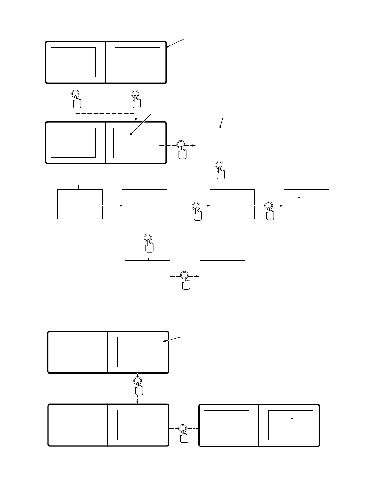
10-4. Reading From Card
Process
Sequence
>C a r d P r e s s
Be low
Mode
Select
Once
Wr i t e
>Read
De l et e
Done
WA R N I NG : Prg1 Will
#1Pul se
035” Steel
Argon– Oxy
Select Once
Press
Be Los t
Lose? Ye s
Press
Parameter
2
Yes
1
Parameter
Select
No
Increase
3
Read Card
to Feeder
Prg 1
Press
Parameter
Select
Prg1 Will
Be Los t
Lose? No
Press
Use Mode Select button to select
Card.
1 Card Display
2 Moving Line
Moving line is under value that can
be changed. Use increase or
decrease button to select program
number to read from card to weld
control.
3 Read Displ a y
Use increase or decrease button to
select weld control program
number where the card program
goes.
#1Pul se
035” Steel
Argon– Oxy
Press
Parameter
Select
Parameter
Select
Read Done
Ca rd Pr g1
to Prg 1
Press
Parameter
Select
10-5. Reading (Or Deleting) From An Empty Card
1
Wr i t e
>Read
De l et e
Done
Wr i t e
Read
De l et e
>Done Press
WA R N I NG :
Ca rdEmp t y
Press
Be low
Parameter
Select Once
#1Pul se
035” Steel
Argon– Oxy
Press
>P r o c e s s
Sequence
Ca rd
1 Warning Display
If there are no programs on the
card, this series of displays appear.
>P r g 2
MIG
Parameter
Select
OM-1595 Page 55
Page 62
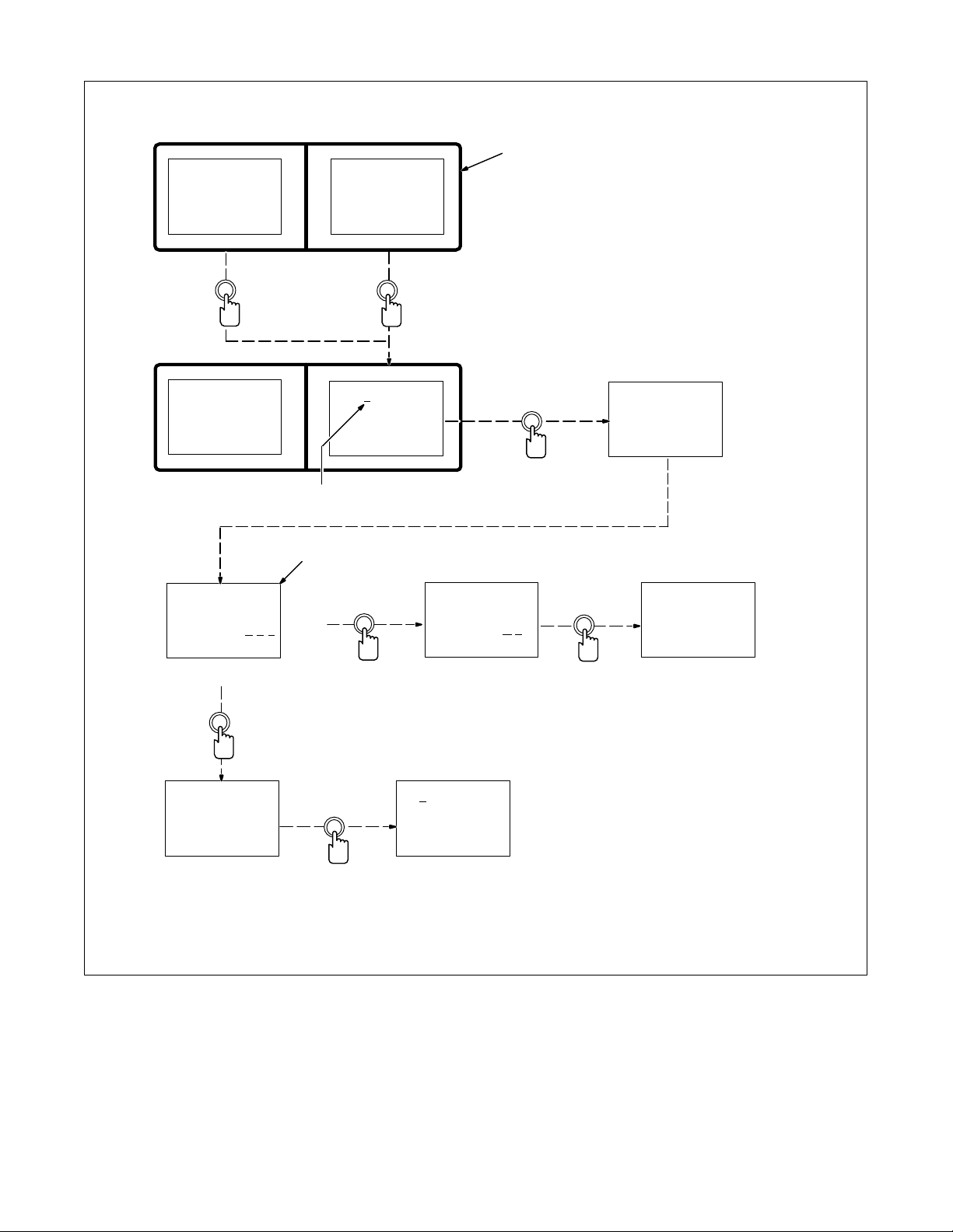
10-6. Deleting Programs From Card
Process
Sequence
>C a r d
Mode
Select
Twice
Press
Be low
Parameter
Select Once
Use Mode Select button to select
Card.
1 Card Display
1
2 Moving Line
Moving line is under value that can
be changed.
3 Delete Display
Select program number to be de-
leted from card.
Wr i t e
Read
>D e l e t e
Done
De l et e
Ca rd Pr g2
Lose? Ye s
Press
Yes
Parameter
Select
Ca rd Pr g2
De l et ed
Press
No
2
3
#2MIG
Press
Increase
De l et e
Ca rd Pr g2
Lose? No
Press
#3 MIG
Press
Parameter
Select
Parameter
Select
WA R N I NG :
#2 MIG
Press
OM-1595 Page 56
Parameter
Select
Page 63
SECTION 11 – SETUP
11-1. Setup Menu
The setup menu provides numerous settings and conditions for the unit operation. Some terminology is unique to the
system and requires an explanation of the function it performs in the system. The following table gives the terminology
and description for each item in the setup menu.
Display Setting Setting Notes
>System Pulse/MIG
MIG Only
>Range 0.0 – 25.0 V
25.0 – 99.9 V
0 – 50 A
50 – 999 A
>Security Prog Number Locks operators out of arc parameter adjustments. Allows limited adjustment range
Off/On
>Access Off/On A programmable software code that prevents access to setup menu without entering
>Mig Type DVC On/Off Enables or disables the non-pulse voltage regulation software in the unit.
>Voltage 14-Pin
Volt Sense
>Arc Start Standard/Hot Start Selection of different arc starting methods for pulse welding. Standard method is a
>Flow Off/On Monitoring function that checks for a flow switch input signal. If no signal is present,
>Polarity Off
On
Positive/Negative
>Jog IPM 50 – 400 IPM Allows setting wire speed for wire advance and wire retract/burnback operations.
>Arc Time 0 – 9999.99 Hours
0 – 999.999 Cycles
No Reset/Reset
>Wire Feed IPM/MPM Allows choosing wire feed speed display in inches per minute or meters per minute.
Standard
Low Speed
High Speed
>Wire Type Hardwire/Softwire Function for loading synergic pulse welding data into static memory. Two selections
>Memory No
Program 1 – 8
System
Allows the user to set the unit as either a Pulse/MIG control or a MIG only control.
Indicates the range from minimum to maximum output of the welding power source
used with the unit (default setting is for a Maxtron 450).
under lock conditions (requires optional data card to use this feature).
proper code and using correct data card (requires optional data card to use this feature).
Allows selecting voltage feedback signal from either the 14-pin cable or voltage sensing leads.
constant current arc start. Hot Start method begins the pulse welding process in
constant voltage, then switches to constant current after establishing the welding arc
(Hot Start is generally used when starting aluminum wire or steel wire at high run-in
wire feed speeds).
unit generates a ”lack of flow” error. Setup allows turning off this function so that software ignores state of the input. The hardware connection is typically a water flow
switch; however, a gas flow switch can be used for the input signal (two switches
connected in series is acceptable to allow monitoring both water and gas flow). When
this function is on, it is active after the preflow sequence until the start of the burnback
sequence.
Check function for polarity at the welding arc. Turning this function on and setting a
polarity causes the software to rely on the user selection for the polarity at the welding
arc. If polarity is incorrect, the software generates an error condition (to allow this
arc. If polarity is incorrect, the software generates an error condition (to allow this
check function to operate properly, the shutdown function must also be enabled,
which the software does automatically after setting the polarity function). When this
function is on, the system automatically sets Voltage to Volt Sense and Shutdown to
On.
Two separate timers that keep track of arc on/of f transitions and arc on time.
Also, allows setting type of wire drive motor as low, standard, or high speed motor.
allow loading data tables for either hardwire or softwire (requires memory reset
operation to load data).
Function to reset data in the current weld schedule back to factory specifications
(program settings) or reset all pulse data tables and operating system data back to
factory specifications.
OM-1595 Page 57
Page 64
Display Setting NotesSetting
>Shutdown Off/On Allows enabling or disabling the voltage shutdown function. Enabling this feature
>Name Card Programs
Off/On
>Program Panel/Remote Enables remote program select function and disables program selection at front panel
>Start Maintain/Momentary Selection for type of start signal to begin a welding operation. Signal choice is either
>Arc Error Off
On (Time)
>VMonitor Off
On (Volts, Time)
>AMonitor Off
On(Time, Amperes,
And Range)
>Stick Check Off/On Function to detect and clear welding wire frozen to the work at the end of a weld.
>Output A Off/Setting Programmable output signal that activates at predetermined times.
>Output B Off/Setting Programmable output signal that activates at predetermined times.
>Burnback Normal/Retract Selection of either conventional burnback setting at arc end or wire retract at arc end.
>SkipWeld Off/On Requires a Start setting of Momentary in the setup menu and a time setting in the
>Software Version Visual display of software version installed in the unit.
causes a checking operation to monitor the arc start. If no voltage is detected after 50
milliseconds from the arc start command, the unit generates an error condition.
Allows changing program names saved on the optional data card.
controls.
maintained or momentary (maintained signal does not provide a time setting for a
timed weld). See Section 11-6.
Checking function to detect when operation exceeds allowable amount of time without
weld current. Programmable on/off setting and a time setting to allow for amount of
time without weld current.
Function to monitor welding arc voltage. If arc voltage goes outside a predefined window for a set amount of time, the unit generates an error condition and the arc ends
(function is generally used to detect wire feeding trouble or lack of shielding gas). The
window is active from run-in to burnback and is centered on the command value. If
arc voltage goes out of the window, but returns within the set time, the timer resets.
Function to monitor welding arc current. If weld current goes outside a set window for
a set amount of time, the unit generates an error condition and the arc ends (function
is generally used to detect wire feeding trouble or lack of shielding gas). The window
is active from run-in to burnback and is centered on the set value. If weld current goes
out of the window, but returns within the set time, the timer resets.
program weld sequence. The welding operation can be cyclical with each start input
signal or continuous for as long as the start signal is present (unit will continue to
cycle through complete welding operation until start input signal is removed).
OM-1595 Page 58
Page 65
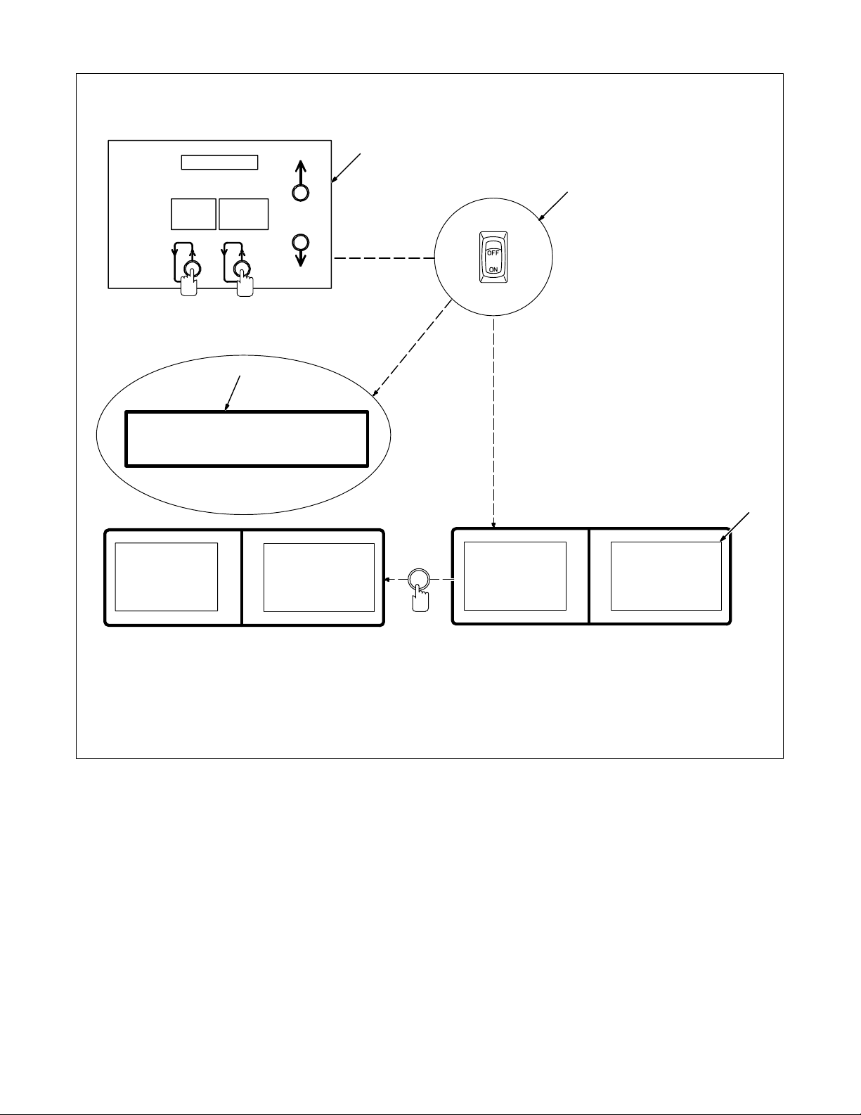
1-2. Accessing The Setup Menu
Mode
Select
Parameter
Select
3
Set up
1 Setup Panel
2 Power Switch
Press and hold down both buttons
1
while turning On unit.
3 Main Display
Main display during setup.
2
4 Setup Display
Follow this procedure any time ac-
cess is required. Once in the setup
displays, use the Mode Select button to select a particular display.
To save any or all of the changes
made while in the setup displays,
and/or to exit the setup displays,
turn power to the unit Of f and back
On.
Sys tem
>Range
Secu r i t y
Access
Main Display
>V o l t M i n
10.0 Vol t
Press
Mode Select
To Change Menu Item
>S y s t e m
Range
Secu r i t y
Access
Setup Display
4
Process
Capabi l i ty
>P u l s e / M i g
OM-1595 Page 59
Page 66
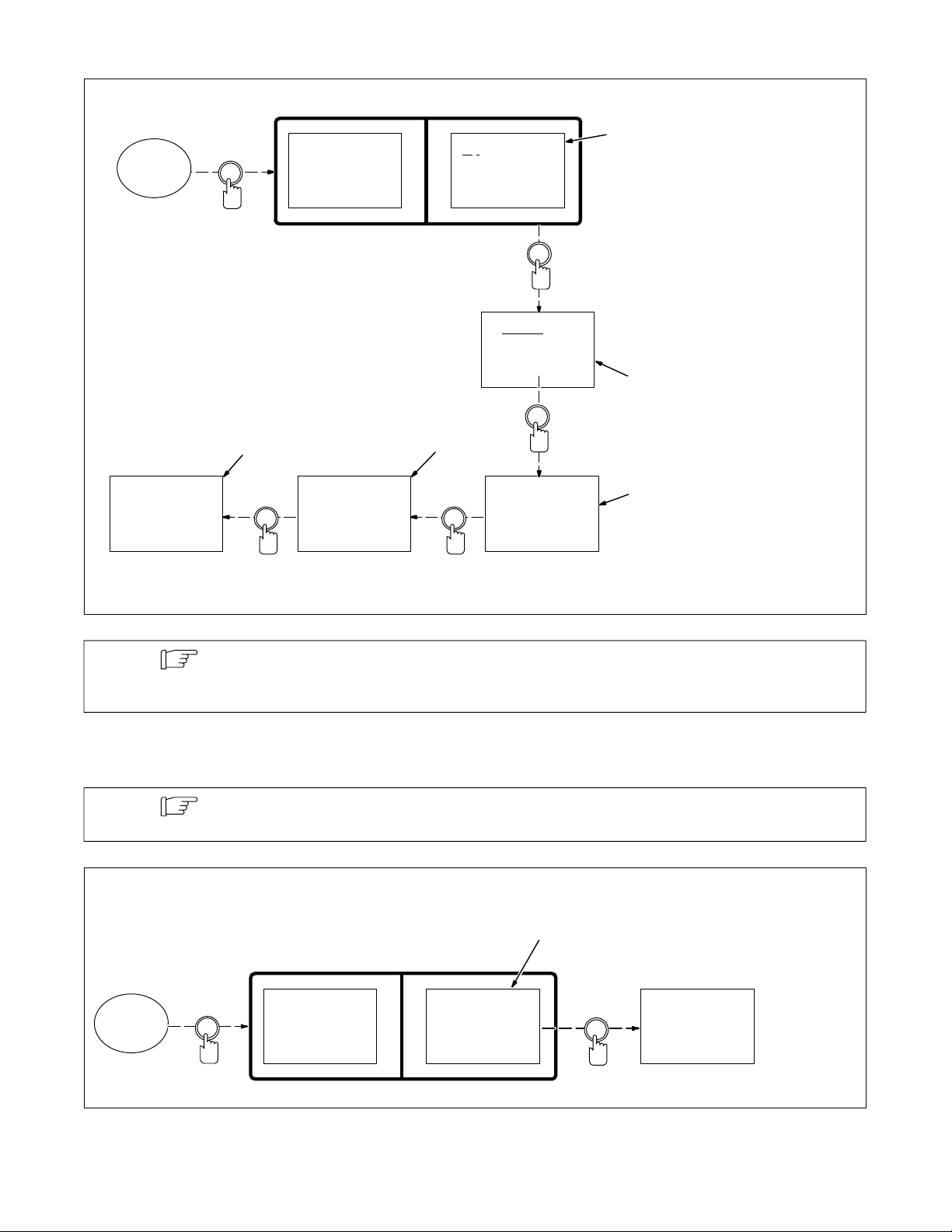
11-3. Example Of Setting Output A In Setup
Press
Access
Setup
Display
Mode Select
Mo n i t o r
Stick
>Ou t p u t A
Ou t pu t B
>O f f
During an Emergency Stop or standby condition,
output A and B revert to Off state.
4
Parameter
Select
On A t
RUN I N
Of f At
>PO S T F L OW
5
Increase/
Decrease
On A t
RUN I N
Of f At
>Seqnc End
Increase/
Decrease
On A t
>PR E F L OW
Of f At
Seqnc End
Increase/
Decrease
On A t
>RU N I N
Of f At
Seqnc End
1Off
Output A is factory set to Off in
1
Setup.
2 On Setting
Press Increase or Decrease button
to change Output A setting.
On provides a selection of
sequences when Output A turns on
during program operation.
3 On At RUNIN
Press Increase or Decrease button
to select RUNIN as the sequence
when Output A turns on.
4 Off Setting
Press Parameter Select button to
move cursor to the Off setting.
Off provides a selection of
2
sequences when Output A turns off
during program operation.
5 Off At POSTFLOW
Press Increase or Decrease button
to select POSTFLOW as the
sequence when Output A turns off.
Continue setup changes or turn off
3
weld control power. When power is
turned on, setup changes will be active in weld control system memory.
Note
Sequence logic for Output A and Output B settings can be checked by pressing the Weld On/Off
button to turn off welding and using a program dry run without welding to verify if settings are
functioning properly.
11-4. Selecting Wire Type
Note
Access
Setup
Display
If wire type is changed, perform a memory reset (see Section 11-5) immediately after selecting
wire type to bring up the correct welding programs.
Press
Mode Select
Arc Time
Wi refeed
>Wi r e t y p e
Display
Wi re Type
In Feeder
>H a r d w i r e
1
1 Wire Type Display
Select soft wire when using alumi-
num wire in the wire feeder . Select
hard wire when using any other kind
of wire.
Wi re Type
In Feeder
>S o f t w i r e
Increase
OM-1595 Page 60
Page 67
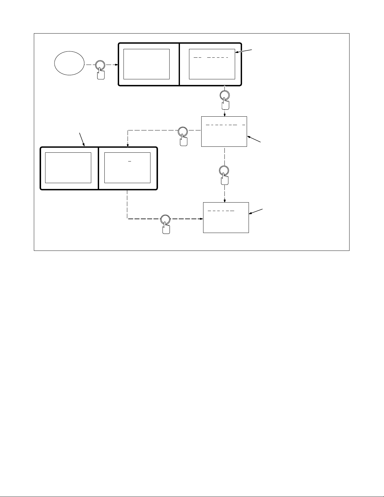
11-5. Resetting Memory
Press
Access
Setup
Display
Mode Select
4
Wi refeed
Mode l
>Me m o r y
Shu tdown
>N o R e s e t
>P r o g r a m 1
Rese t
Increase/
Decrease
1 No Reset
Memory cannot be reset.
1
2 Program Reset
Press Parameter Select button to
reset last active program to original
factory program settings. All other
program and setup information
remains the same.
3 System Reset
Press Parameter Select button to
reset programs and setup to original factory settings. System, Arc
Time, and Model Type settings are
not affected by the system reset.
4 Reset (Default) Displays
>P r o c e s s
Sequence
Ca rd
>P r g 1
Pu lse
035” Steel
Argon Oxy
Parameter
Parameter
Select
Select
Press
>S y s t e m
Rese t
Press
Increase/
Decrease
2
3
11-6. Starting Method For A Program
A customer supplied start and stop closure must be provided to the weld control to run programs. An optional pendant
control, that provides start, stop, and Emergency Stop buttons, is available for connecting to the weld control. Section
3-12 has input/output connection information for the start and stop closures. The start and stop closures can be either
maintained or momentary depending on the selection made in the setup menu (see Section 11-1).
Maintained Closure – When using a maintained closure, the weld control will run a continuous weld sequence until
the closure opens or a stop input closure is made which signals the control to begin the weld end sequences. A typical
sequence for the welding operation is as follows:
Start Input Closure
Preflow (user preset timed sequence)
Run-In (user preset timed sequence)
Weld (continuous sequence for time of input closure)
Start Input Open
Crater Fill (user preset timed sequence)
Burnback (user preset timed sequence)
Postflow (user preset timed sequence)
Standby (program can be started again or operator can select a new program and start it)
Conditions that apply to the maintained closure are as follows:
All weld sequences have a time duration before advancing to the next sequence, except weld and standby.
OM-1595 Page 61
Page 68

If a maintained stop input closure is made during the weld sequence and the start input closure is still present, the
weld control will advance sequences the same as a start input open condition.
If a maintained stop input closure is made during the beginning sequences before the weld sequence, the weld
control stops the current sequence and returns to standby.
If a maintained stop input closure is present before the start input closure, once the start input closure is made, the
weld control will remain in standby.
An Emergency Stop causes the current sequence to stop operation and the weld control returns to standby. The
standby state cannot change until the operator clears the Emergency Stop condition.
Momentary Closure – When using a momentary closure, the weld control will run a timed or continuous weld se-
quence at a start input closure that is held for a minimum of 50 milliseconds. Stopping a weld sequence can be done by
entering a time value into the weld parameter of the sequence menu and welding will stop when this time elapses.
Another method to stop a welding sequence is if a momentary stop input closures is made during the timed weld sequence and welding stops before the time elapses. If zero (0) time is entered into the weld parameter, the weld
sequence will be continuous until a stop input closure is made to advance program sequences. A typical sequence for
the welding operation is as follows:
Start Input Closure (50 millisecond minimum closure)
Preflow (user preset timed sequence)
Run-In (user preset timed sequence)
Weld (sequence for elapsed time in weld parameter)
Weld Parameter Time Elapses Or Stop Input Closure (50 millisecond minimum closure)
Crater Fill (user preset timed sequence)
Burnback (user preset timed sequence)
Postflow (user preset timed sequence)
Standby (program can be started again or operator can select a new program and start it)
Conditions that apply to the momentary closure are as follows:
The start or stop input closure must be present for a minimum of 50 milliseconds for the weld control to receive the
signal.
An Emergency Stop causes the current sequence to stop operation and the weld control returns to standby. The
standby state cannot change until the operator clears the Emergency Stop condition.
Skip Weld requires a Start setting of Momentary in the setup menu and a time setting in the program weld
sequence. The welding operation can be cyclical with each start input signal or continuous for as long as the start
signal is present (unit will continue to cycle through complete welding operation until start input signal is removed).
11-7. Remote Program Setting
If remote program select feature is desired, set the program function to remote in the weld control setup menu (see
Section 11-2 for instructions to access the setup menu).
See the following table for the remote program select binary code.
Program No. Output A Output B Output C
1 Off Off Off
2 On Off Off
3 Off On Off
4 On On Off
5 Off Off On
6 On Off On
7 Off On On
8 On On On
OM-1595 Page 62
Page 69
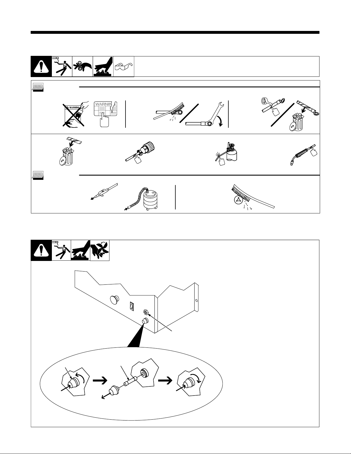
SECTION 12 – MAINTENANCE & TROUBLESHOOTING
12-1. Routine Maintenance
Disconnect power before maintaining.
3 Months
Replace
unreadable
labels.
Replace
cracked
parts.
Check
14-pin
cord.
Clean an d
tighten
weld
terminals.
6 Months
Blow out or vacuum
inside. During heavy
service, clean
monthly.
OR
12-2. Circuit Breaker CB1 And Fuse F1
3
Check gas
hose and
fittings.
Clean
drive
rolls.
Repair or
replace
cracked
weld
cable.
Check
gun
cable.
If fuse F1 opens, the weld control
shuts down. To check or change
F1, proceed as follows:
1 Fuse Holder Cover
2 Fuse F1 (See Parts List For
Rating)
3 Circuit Breaker CB1
CB1 protects the wire feed motor
from overload. If CB1 opens, the
wire feed motor stops. Check for
jammed wire, binding drive gear, o r
misaligned drive rolls. Correct
problem.
Allow cooling period and manually
reset breaker .
1
Push And Turn
2
Pull Out And
Replace F1
Push And Turn
Ref. ST-801 440 / Ref. ST-800 185-A
OM-1595 Page 63
Page 70
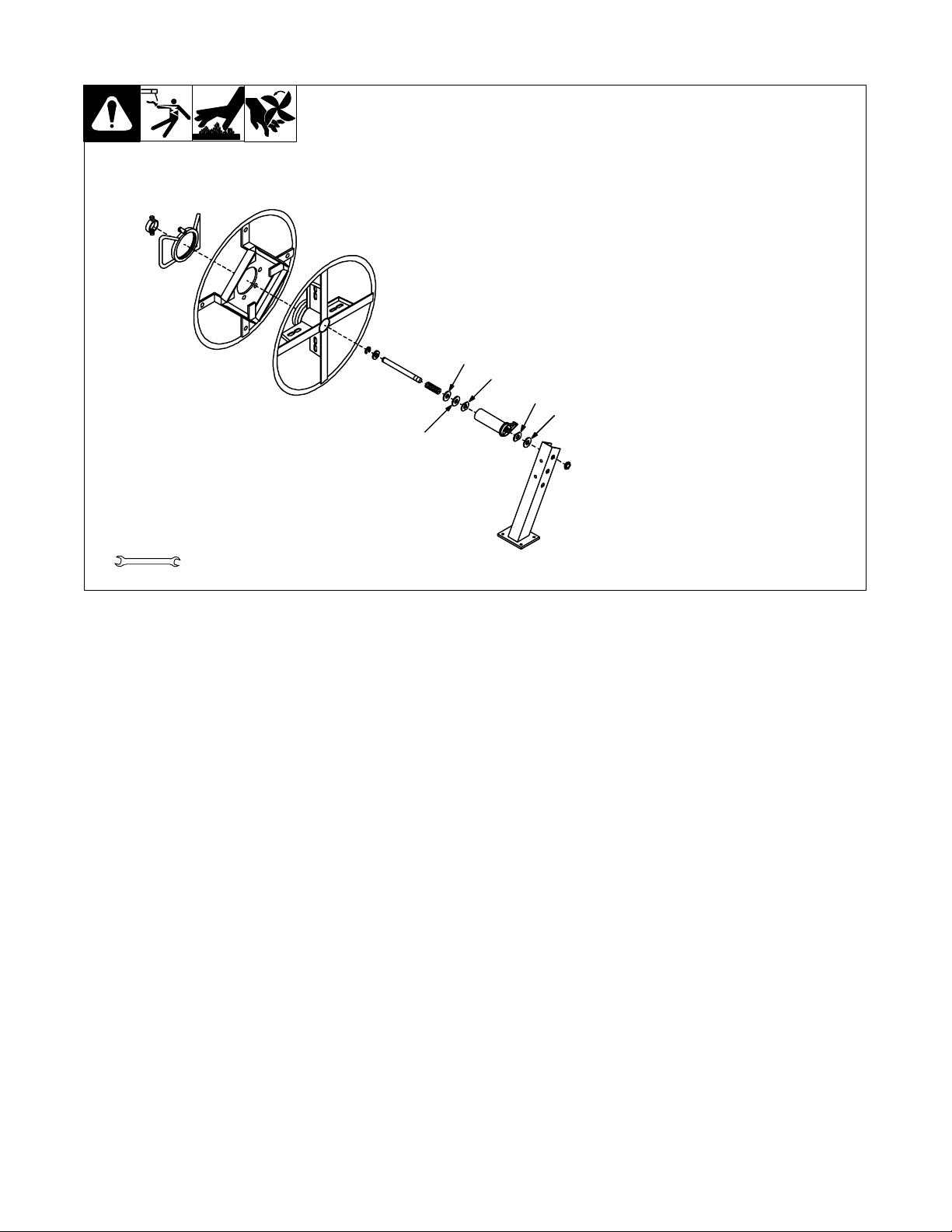
12-3. Replacing The Hub Assembly
Turn Off weld control and welding
power source. Retract wire onto
spool and remove. Take hub apart as
shown.
1 Keyed W asher
2 Fiber Washer
3 Brake Washer
Replace worn or broken parts (see
Parts List), and slide parts onto shaft
in order shown.
Tighten tension adjustment nut until a
slight force is needed to turn hub. Install welding wire (see Sections 3-18
and 3-19).
1
3
3
2
2
Tools Needed:
9/16 in
Ref. ST-045 315-L
OM-1595 Page 64
Page 71
12-4. Error Messages
1
Memo r y CRC PRG X
2
Memo r y RANGE PRG X
3
NO VOLTS SENSED
4
NO TACH SENSED
5
ARC END PROBLEM
6
NO ARC START
7
AUTOSETUP YES?
8
1 Memory CRC Error Display
Corrupted program data has been
detected or loaded. The “X” value
indicates the program number.
May be caused by incompatible
information on the data card or bad
memory.
2 Memory Range Error Display
Improper welding power source
range is selected. The “X” value
indicates the program number.
May be caused by improper range
settings or improper data loaded into
the interface unit.
3 No Volts Sensed Error Display
The arc voltage sense circuit did not
receive feedback within the required
time after an arc was established.
May be caused by an inability to
establish an arc in the pulse
schedule, or a lack of voltage
feedback.
4 No Tach Sensed Error Display
The motor tachometer feedback is
not reaching the control.
May be caused by obstructions in the
wire feed system or a faulty wire drive
system.
5 Arc End Problem Error Display
Trouble is occurring at arc end.
May be caused by obstructions in the
wire feed system or a faulty wire drive
system.
6 No Arc Start Error Display
Trouble is occurring at arc start.
May be caused by obstructions in the
wire feed system or a faulty wire drive
system.
7 Autosetup Display
Message appears when program
data card is used at power up of the
weld control.
8 Please Wait Display
Message appears while using the
program data card during the
automatic setup operation.
PLEASE WAI T
OM-1595 Page 65
Page 72
1
ERROR – STOP CYCLE
2
ERROR CARD READ
3
NO ARC
4
WIRE ST ICK DETECTED
5
VOLT MONI TOR ERROR
6
WRONG POL AR I TY
7
NO FLOW DETECTED
8
GND CURRENT DETECT
9
AMP MONI TOR ERROR
1 Error – Stop Cycle Display
Message appears when an error is
detected during welding.
Stop welding operation to see detail
message for type of error detected.
2 Error Card Read Display
The card reader is not working
properly.
May be caused by a bad data card, a
bad data card reader, a faulty
microprocessor circuit board, or a
wiring problem.
3 No Arc Error Display
No welding arc was established for
the program welding operation.
4 Wire Stick Error Display
The welding wire has stuck to the
workpiece at the end of the weld.
May be caused by poor weld
conditions.
5 Arc Monitor Time Out Error Dis-
play
Welding arc is operating outside the
window set by weld parameters for a
user set time period.
May be caused by an inoperable wire
drive, absence of shield gas, or improperly operating welding power
source.
6 Wrong Polarity
Wrong polarity was selected during
the setup procedure (see Section 11).
Check for proper connection of
voltage sensing leads and weld cable
connections for the proper polarity at
the welding power source.
7 No Coolant Flow
When flow monitor function is set to
On during the setup procedure and
no coolant flow input signal is present
at the weld control (see Section 11).
8 Ground Current Detect Error
Display
Weld current has been detected in
the earth ground connection.
May be caused by a conductor
making connection to the unit
chassis.
9 Amp Monitor Time Out Error
Display
Welding arc is operating outside the
window set by weld parameters for a
user set time period.
May be caused by an inoperable wire
drive, absence of shield gas, or improperly operating welding power
source.
OM-1595 Page 66
Page 73
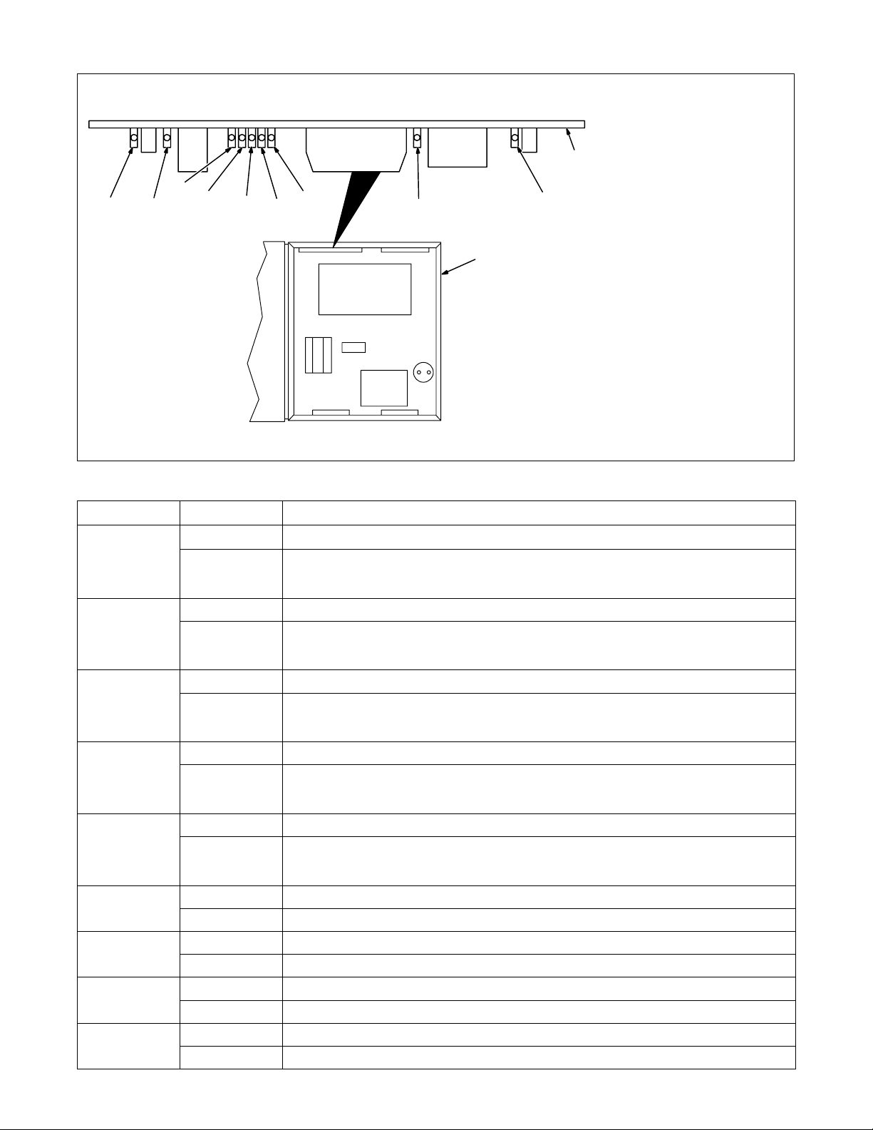
12-5. Interface Board PC5 Diagnostic LED’s
LED4
LED1 LED2
LED9
LED8
LED7
LED6
LED3
1 Microprocessor Weld Control
2 Interface Board PC5
Diagnostic LED’s are visible inside
unit, located on edge of Interface
Board PC5 facing front of unit.
2
Refer to the following table for
information on diagnostic LED’s.
LED5
1
Close door after checking diagnostic
LED’s.
ST-801 094-A
LED Status Diagnosis
1 On Indicates +15 volts dc present on interface board PC5 with respect to power source common.
Off If LED 1 is off and LED’s 2 thru 5 are on, replace interface board PC5. If LED 1 is off and LED’s 2 thru 5
2 On Indicates –15 volts dc present on interface board PC5 with respect to power source common.
Off If LED 2 is off and LED’s 1, 3, 4, and 5 are on, replace interface board PC5. If LED 2 is off and LED’s 1,
3 On Indicates +15 volts dc present on interface board PC5 with respect to dc circuit common.
Off If LED 3 is off and LED’s 1, 2, 4, and 5 are on, replace interface board PC5. If LED 3 is off and LED’s 1,
4 On Indicates –15 volts dc present on interface board PC5 with respect to dc circuit common.
Off If LED 4 is off and LED’s 1, 2, 3, and 5 are on, replace interface board PC5. If LED 4 is off and LED’s 1,
5 On Indicates +5 volts dc present on interface board PC5 with respect to dc circuit common.
Off If LED 5 is off and LED’s 1 thru 4 are on, replace interface board PC5. If LED 5 is off and LED’s 1 thru 4
6 On Indicates contactor is not energized, normal standby mode.
Off Indicates contactor is energized.
7 On Indicates CV mode is selected.
Off Indicates CC mode is selected.
8 On Indicates gas valve GS1 is not energized, normal standby mode.
Off Indicates gas valve GS1 is energized.
9 On Indicates wire feed motor M1 is not running, normal standby mode.
Off Indicates wire feed motor M1 is running.
are off, check Power switch S1, integrated rectifier SR1, and motor board PC3. Replace S1, SR1, and
PC1 if necessary.
3, 4, and 5 are off, check Power switch S1, integrated rectifier SR1, and motor board PC3. Replace S1,
SR1, and PC1 if necessary.
2, 4, and 5 are off, check Power switch S1, integrated rectifier SR1, and motor board PC3. Replace S1,
SR1, and PC1 if necessary.
2, 3, and 5 are off, check Power switch S1, integrated rectifier SR1, and motor board PC3. Replace S1,
SR1, and PC1 if necessary.
are off, check Power switch S1, integrated rectifier SR1, and motor board PC3. Replace S1, SR1, and
PC1 if necessary.
OM-1595 Page 67
Page 74
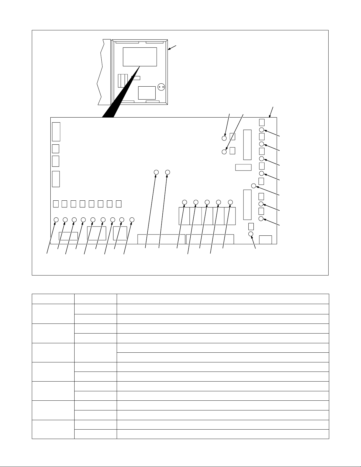
12-6. Customer Interface Board PC4 Diagnostic LED’s
1
1 Microprocessor Weld Control
2 Customer Interface Board PC4
Diagnostic LED’s are visible inside
unit, located on PC4 mounted to
center panel facing front of unit.
Refer to the following table for
information on diagnostic LED’s.
Close door after checking diagnostic
LED’s.
2
LED21LED20
LED18
LED17
LED16
LED19
LED15
LED6
LED10
LED Status Diagnosis
1
2
3 Not used
4
5
6
7
LED11
LED3LED5
LED1LED2 LED9 LED8
LED4 LED7
On Input signal On for RPS8-A.
Off Input signal Off for RPS8-A.
On Input signal On indicates weld enable is turned on.
Off Input signal Off indicates weld enable is turned off.
On Input signal On for RPS8-C.
Off Input signal Off for RPS8-C.
On Input signal On for shielding gas purge.
Off Input signal Off for shielding gas purge.
On Input signal On for Jog retract.
Off Input signal Off for Jog retract.
On Indicates +24 volts dc present on customer interface board PC4 with respect to power source common.
Off No +24 volts dc at customer interface board PC4.
LED23
LED24
LED26
LED25 LED12
LED22
LED14
LED13
OM-1595 Page 68
Page 75

LED DiagnosisStatus
10
11
12
13
14
15
16
17
18
19
20
8
9
On Indicates –15 volts dc present on interface board PC4 with respect to dc circuit common.
Off No –15 volts dc at customer interface board PC4.
On Indicates +15 volts dc present on interface board PC4 with respect to dc circuit common.
Off No +15 volts dc present at customer interface board PC4.
On Input signal On for Jog advance.
Off Input signal Off for Jog advance.
On Input signal On for RPS8-B.
Off Input signal Off for RPS8-B.
On Input signal On indicates water switch for coolant system is turned on.
Off Input signal Off indicates water switch for coolant system is turned off.
On Input signal On indicates manual weld selection is on.
Off Input signal Off indicates manual weld selection is off.
On Input signal On indicates error reset signal is present.
Off Input signal Off indicates no error reset signal is present.
On Input signal On indicates a start signal is present.
Off Input signal Off indicates no start signal is present.
On Input signal On indicates a remote increase signal is present.
Off Input signal Off indicates no remote increase signal is present.
On Input signal On indicates a remote decrease signal is present.
Off Input signal Off indicates no remote decrease signal is present.
On Input signal On indicates a Stop signal is present.
Off Input signal Off indicates no Stop signal is present.
On Input signal On indicates a ground current signal is present.
Off Input signal Off indicates no ground current signal is present.
On Input signal On indicates Inc/Dec Selector feature for remote operation is turned on.
Off Input signal Off indicates Inc/Dec Selector feature for remote operation is turned off.
21 Not used
22
23
24
25
26
On Output signal On to indicate arc enable is turned on.
Off Output signal Off indicates arc enable is turned off.
On Output signal On indicates Output A signal is present.
Off Output signal Off indicates no Output A signal.
On Output signal On indicates Output B signal is present.
Off Output signal Off indicates no Output B signal.
On Output signal On indicates an arc is detected.
Off Output signal Off indicates no arc is detected.
On Output signal On indicates an error occurred in operation.
Off Output signal Off indicates no error is present.
OM-1595 Page 69
Page 76
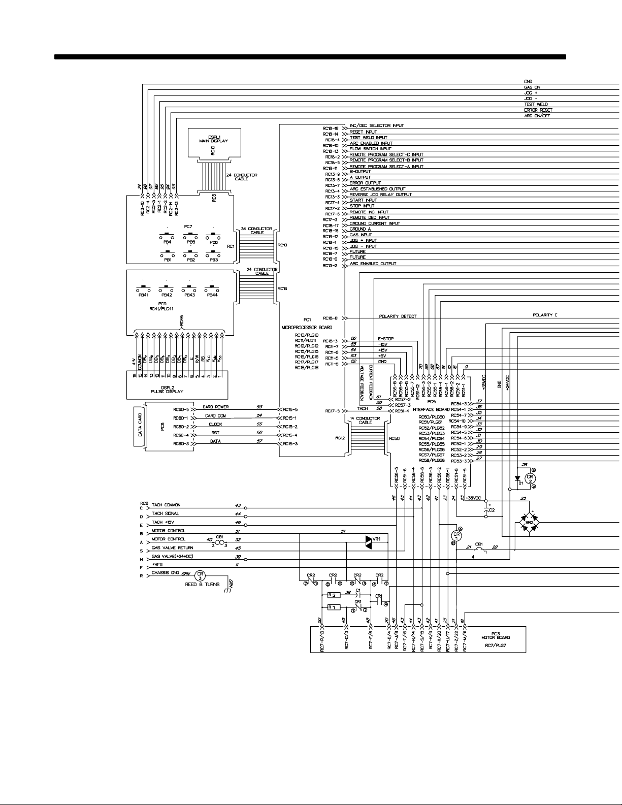
SECTION 13 – ELECTRICAL DIAGRAMS
OM-1595 Page 70
Figure 13-1. Circuit Diagram For Microprocessor Weld Control
Page 77
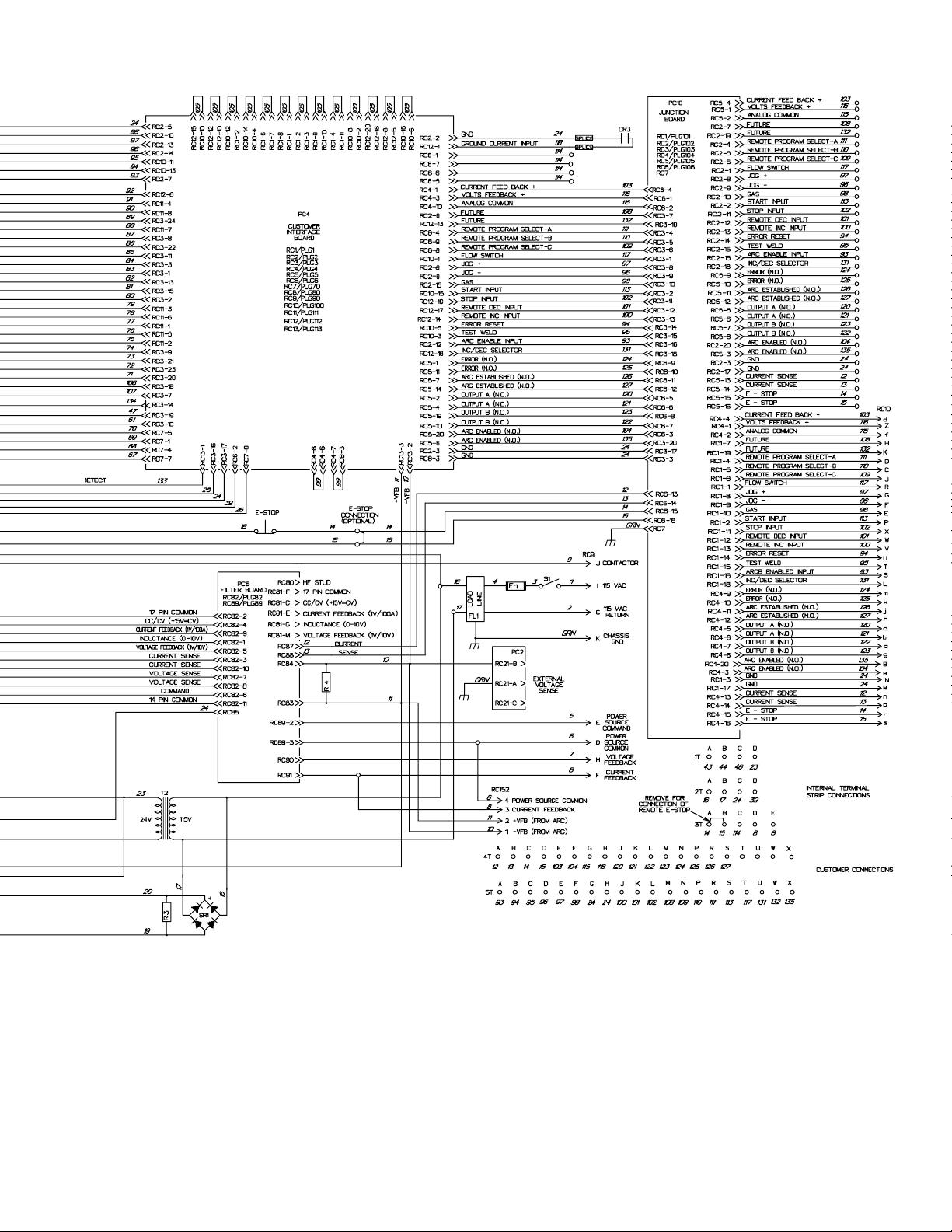
SD-181 441-B
OM-1595 Page 71
Page 78
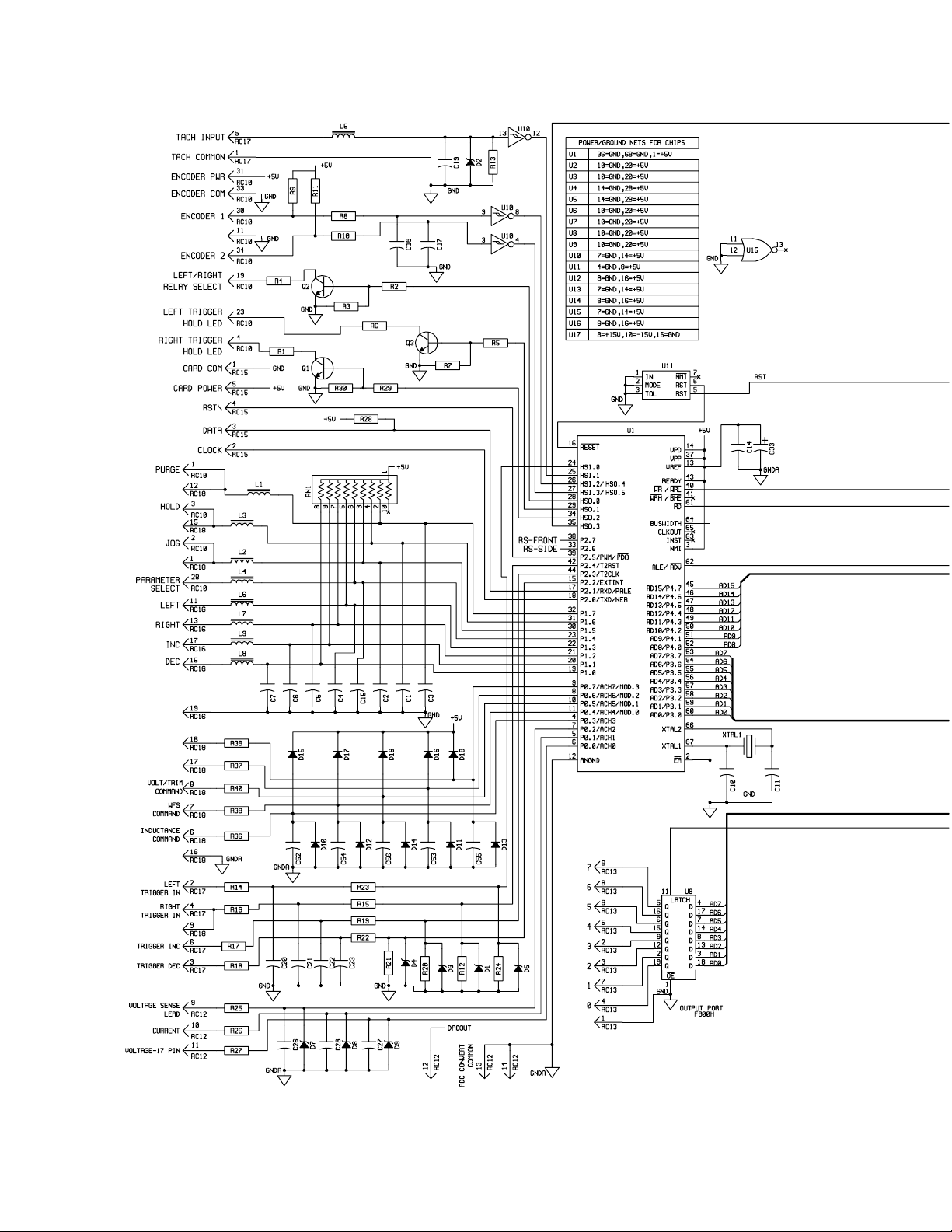
OM-1595 Page 72
Figure 13-2. Circuit Diagram For Microprocessor Board PC1
Page 79
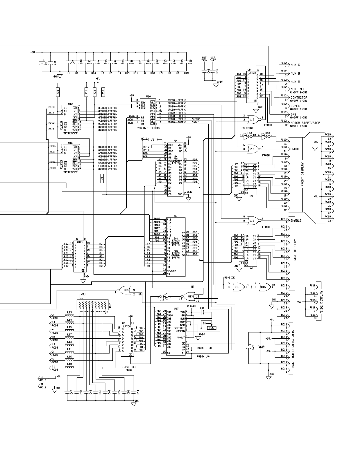
SD-161 039-A
OM-1595 Page 73
Page 80
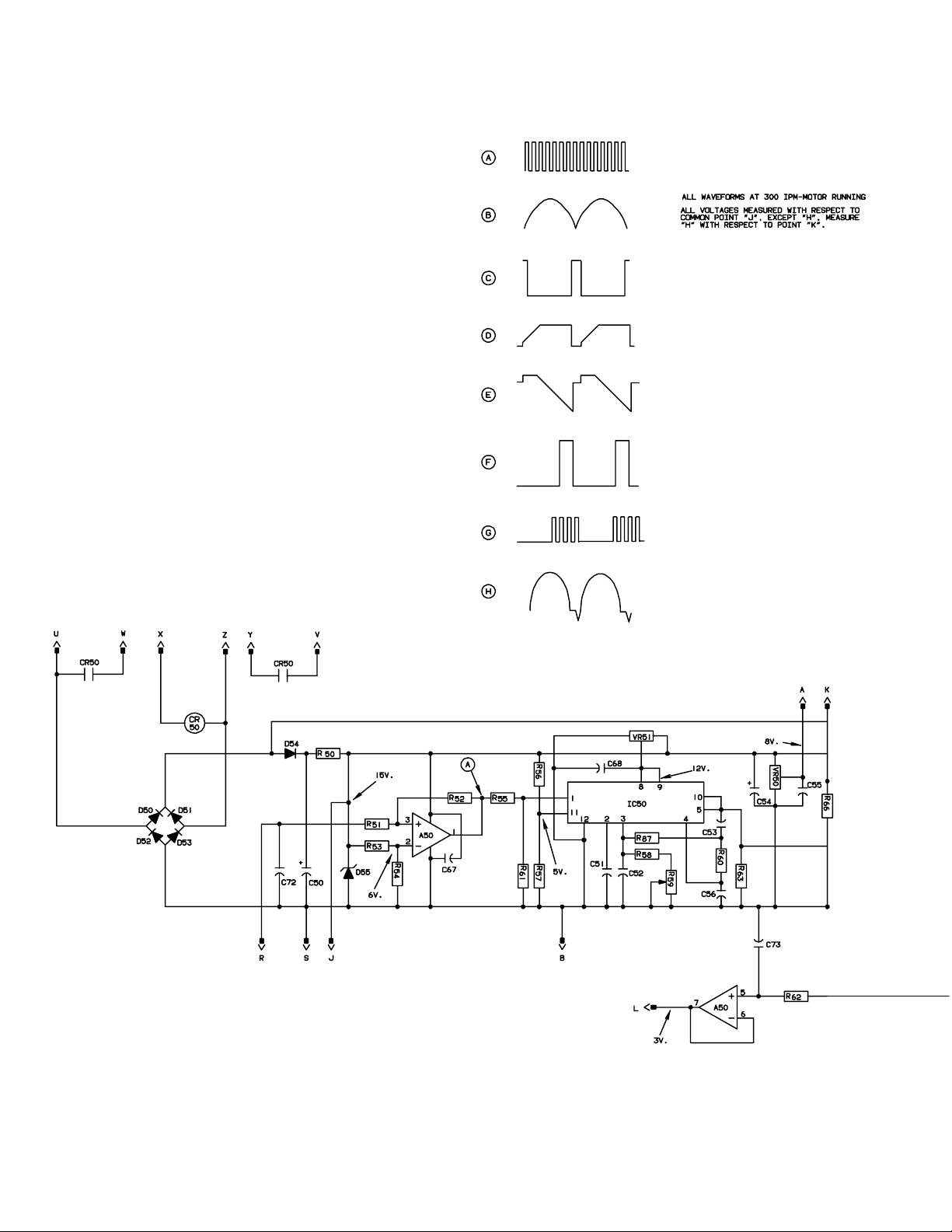
OM-1595 Page 74
Figure 13-3. Circuit Diagram For Motor Board PC3
Page 81
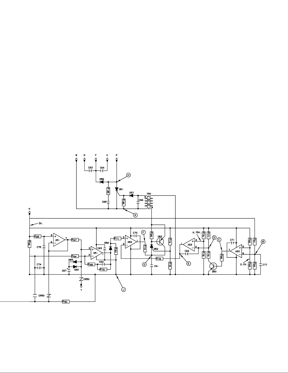
SD-083 388-B
OM-1595 Page 75
Page 82
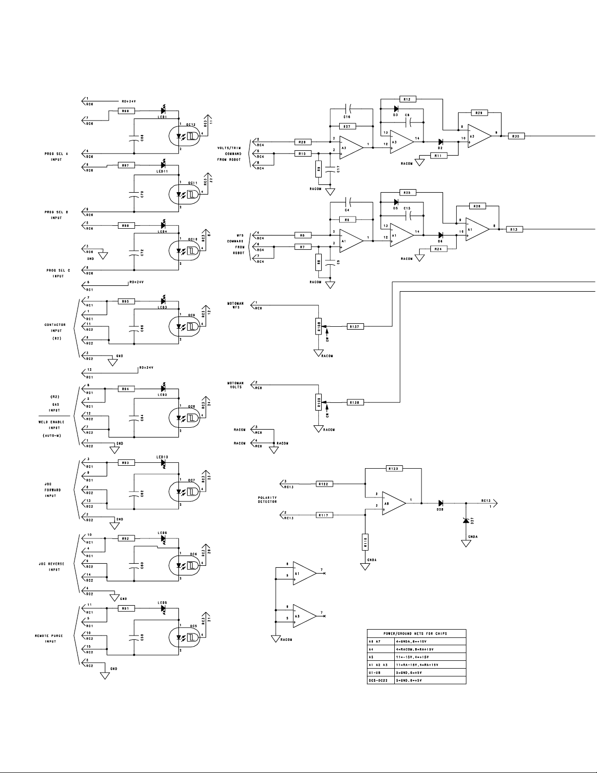
OM-1595 Page 76
Figure 13-4. Circuit Diagram For Customer Interface Board PC4 (Part 1 Of 2)
Page 83
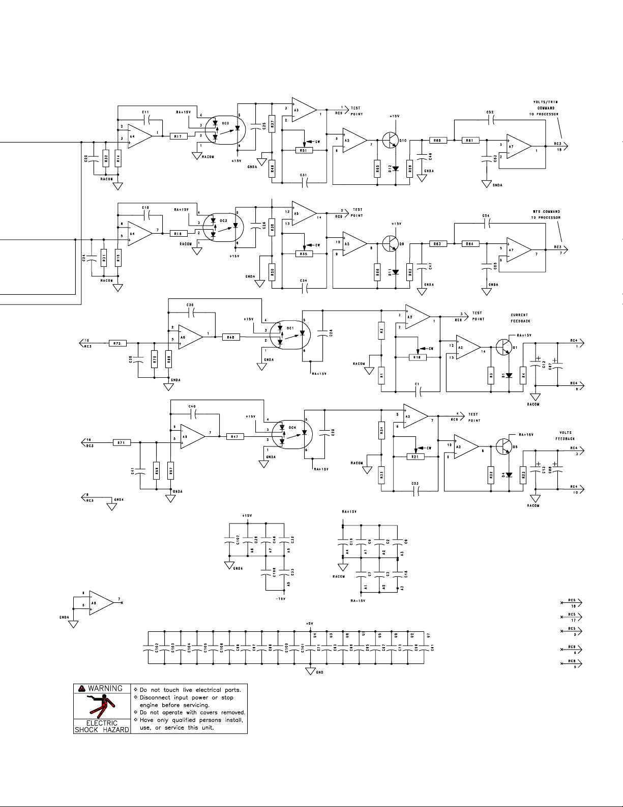
SD-180 191 (Part 1 of 2)
OM-1595 Page 77
Page 84
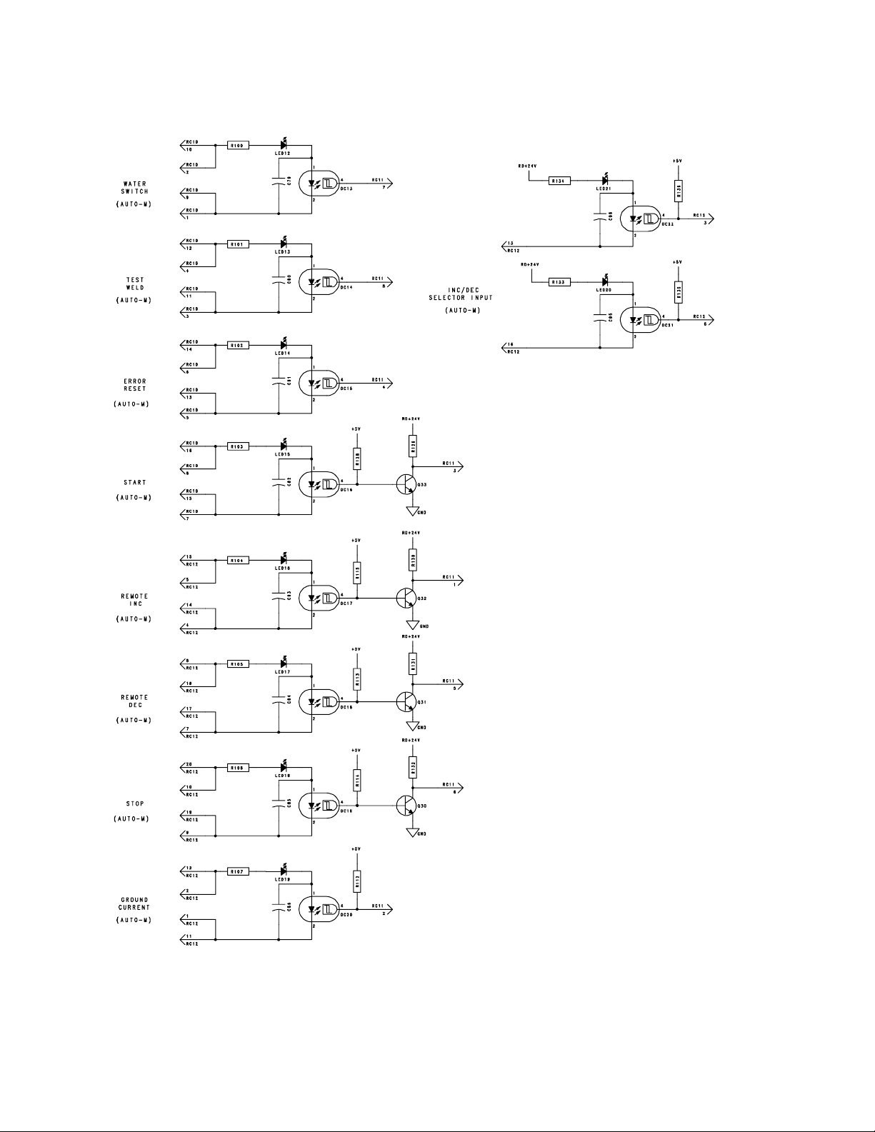
OM-1595 Page 78
Figure 13-5. Circuit Diagram For Customer Interface Board PC4 (Part 2 Of 2)
Page 85
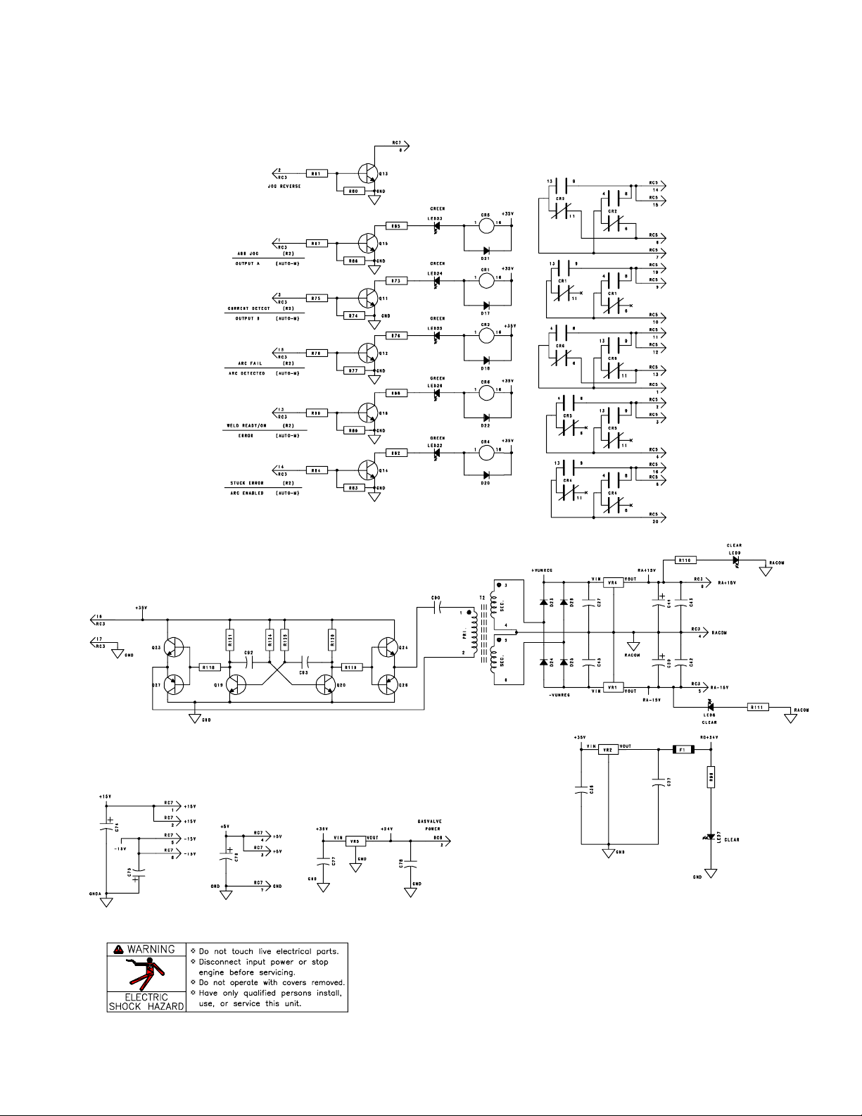
SD-180 191 (Part 2 of 2)
OM-1595 Page 79
Page 86
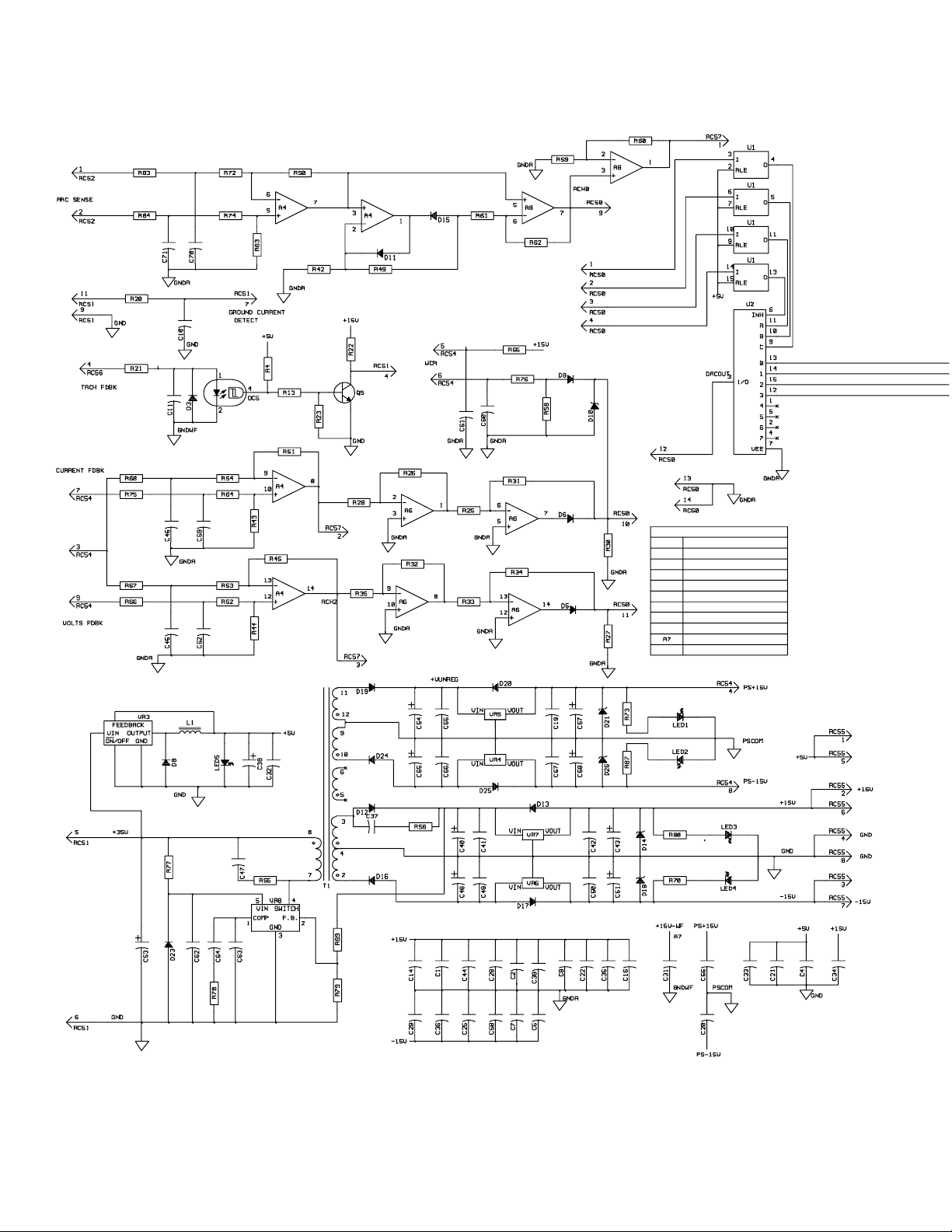
OM-1595 Page 80
Figure 13-6. Circuit Diagram For Interface Board PC5
Page 87
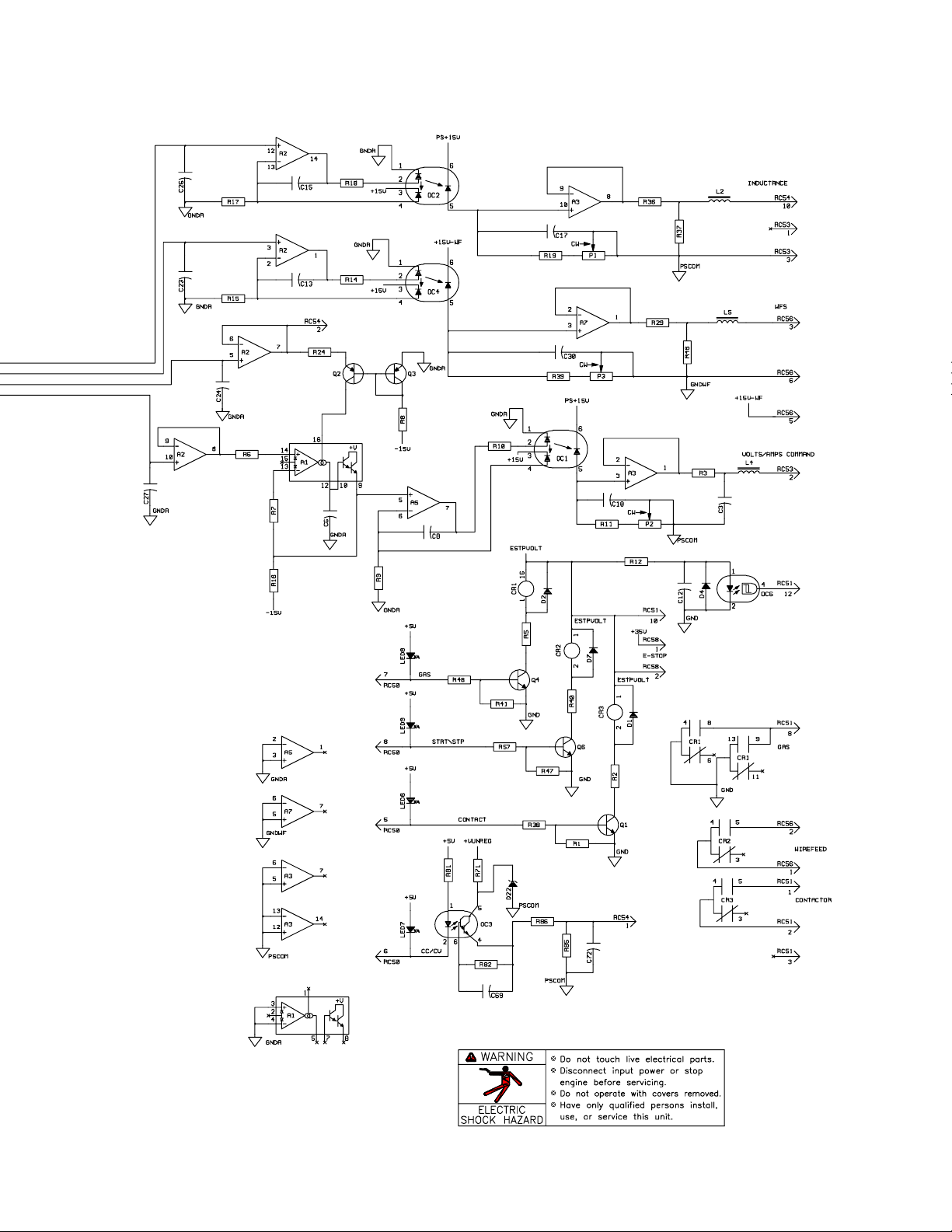
210 704-A
OM-1595 Page 81
Page 88
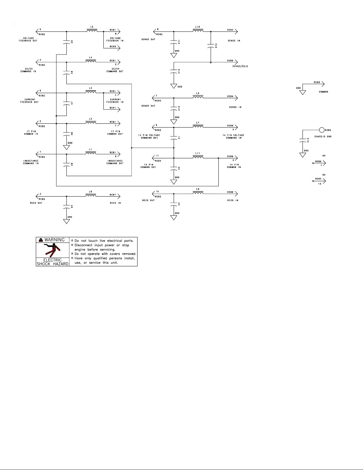
Figure 13-7. Circuit Diagram For Filter Board PC6
SB-179 739
OM-1595 Page 82
Page 89
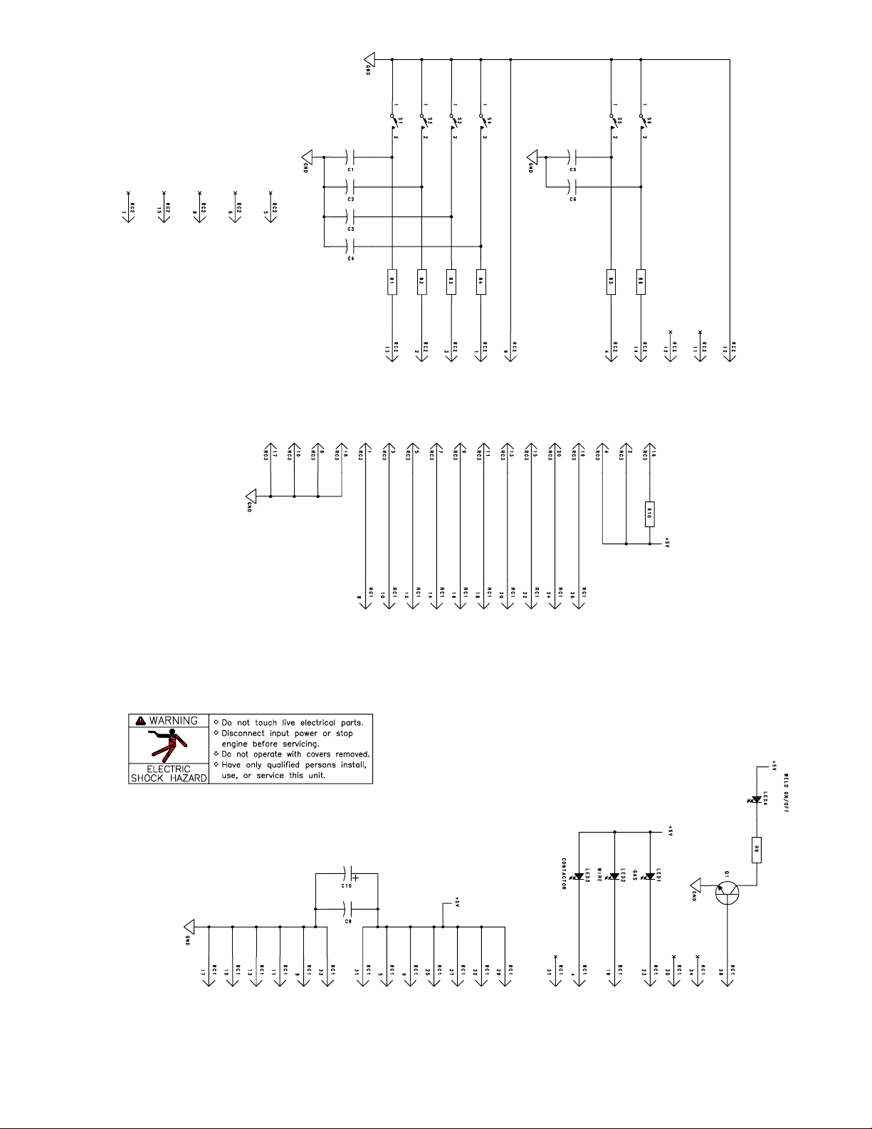
Figure 13-8. Circuit Diagram For VFD Switch Board PC7
SC-177 335-A
OM-1595 Page 83
Page 90
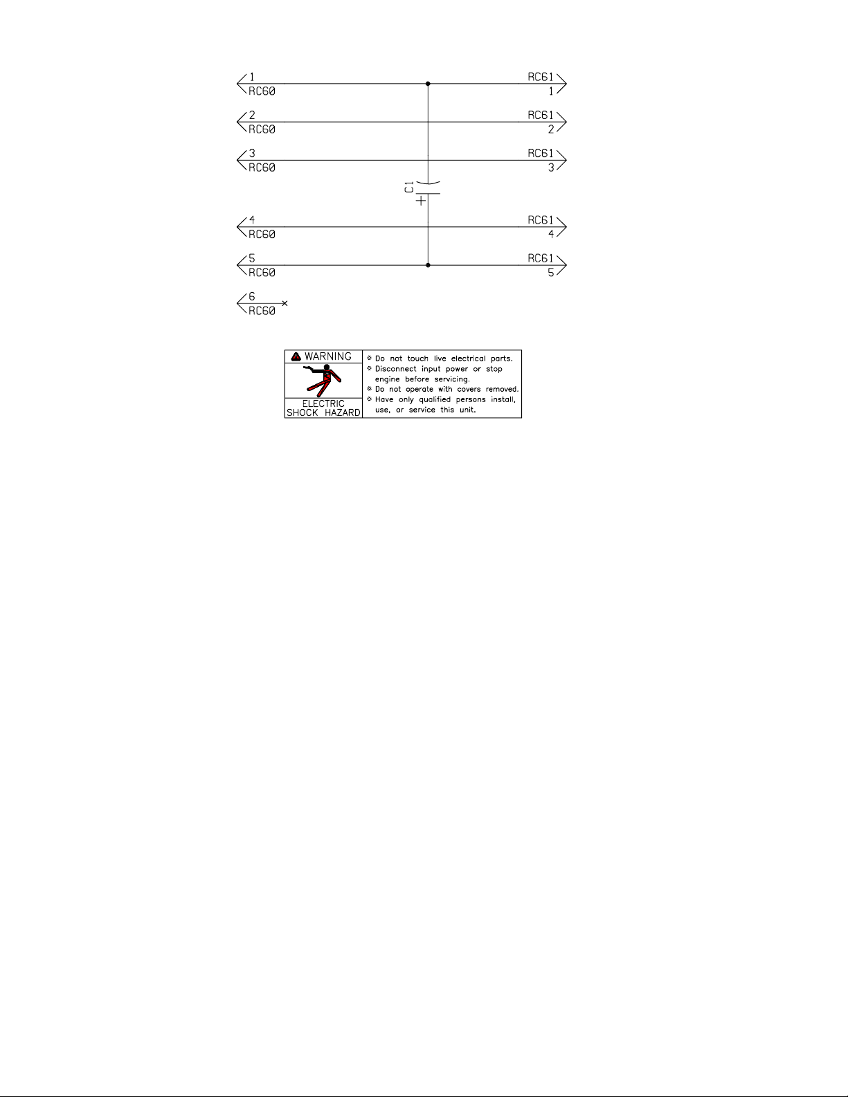
Figure 13-9. Circuit Diagram For Data Card Board PC8
SA-156 626-A
OM-1595 Page 84
Page 91
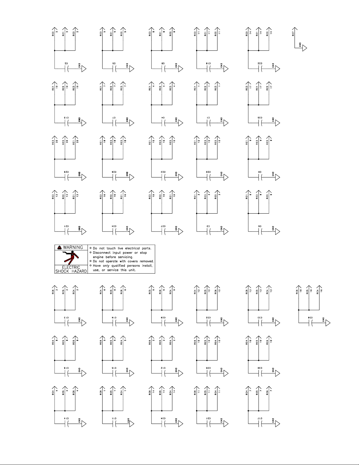
Figure 13-10. Circuit Diagram For Junction Board PC10
SC-176 534
OM-1595 Page 85
Page 92
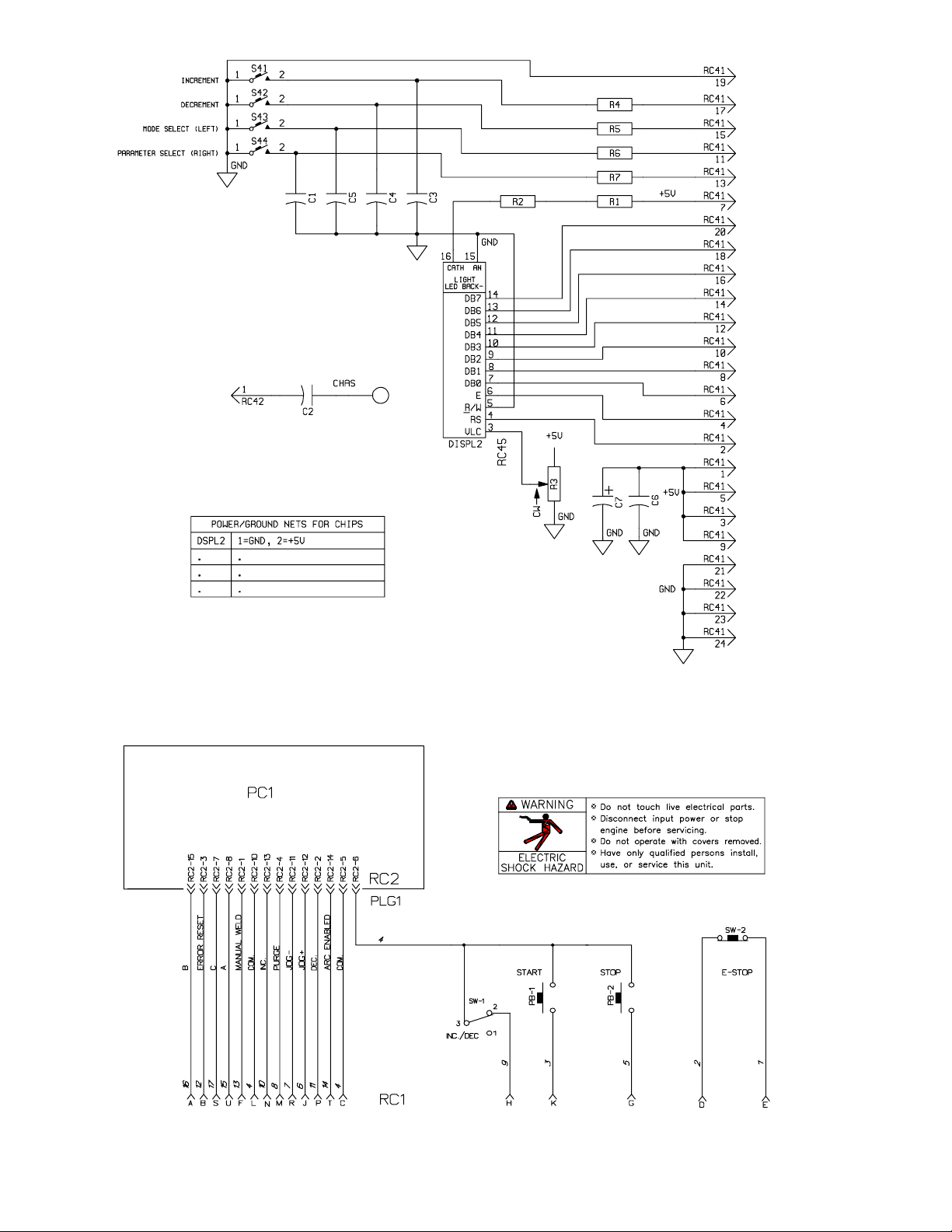
Figure 13-11. Circuit Diagram For Pulse Display Board PC9
SA-158 163
OM-1595 Page 86
Figure 13-12. Circuit Diagram For Optional Operator Pendant
SA-178 857–A
Page 93

Notes
OM-1595 Page 87
Page 94
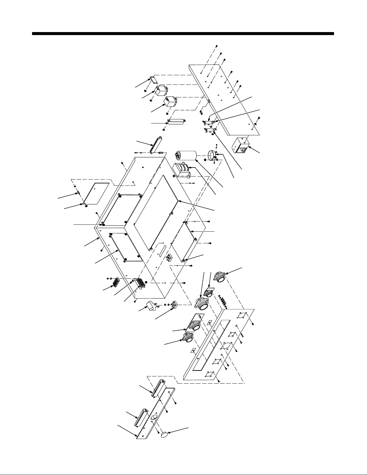
Hardware is common and
not available unless listed.
15
SECTION 14 – PARTS LIST
10
20
19
2122
17 18
16
23
24
25
262728
14
13
12
29
11
10
9
8
7
6
5
4
3
30
31
32
OM-1595 Page 88
2
1
33
Figure 14-1. Case Section w/Components
ST-801 441
Page 95

Item
No. Quantity
Dia.
Mkgs.
Part
No.
Description
Figure 14-1. Case Section w/Components
1 180 256 PLATE, terminal mtg 1. . . . . . . . . . . . . . . . . . . . . . . . . . . . . . . . . . . . . . . . . . . . . . . . . . . . . . . . . . . . . . .
2 PLG105 131 052 CONNECTOR & SOCKETS 1. . . . . . . . . . . . . . . . . . . . . . . . . . . . . . . . . . . . . . . . . . . . . . . .
3 PLG102 162 382 CONNECTOR & SOCKETS 1. . . . . . . . . . . . . . . . . . . . . . . . . . . . . . . . . . . . . . . . . . . . . . . .
4 RC9 143 425 CONNECTOR, circ MS/CPC 14 pin sz 20 1. . . . . . . . . . . . . . . . . . . . . . . . . . . . . . . . . . . . . . . .
PLG89 131 204 CONNECTOR & SOCKETS 1. . . . . . . . . . . . . . . . . . . . . . . . . . . . . . . . . . . . . . . . . . . . . . . . . . . . .
5 PC6 159 477 CIRCUIT CARD, HF filter (Prior to KG091221) 1. . . . . . . . . . . . . . . . . . . . . . . . . . . . . . . . . . . .
5 PC6 179 741 CIRCUIT CARD ASSEMBLY, HF filter (Eff w/KG091221) 1. . . . . . . . . . . . . . . . . . . . . . . . . . .
PLG82 158 720 CONNECTOR & SOCKETS 1. . . . . . . . . . . . . . . . . . . . . . . . . . . . . . . . . . . . . . . . . . . . . . . . . . . . .
6 SR1,2 035 704 RECTIFIER, integ 40A 800V 2. . . . . . . . . . . . . . . . . . . . . . . . . . . . . . . . . . . . . . . . . . . . . . . . .
7 C2 169 080 CAPACITOR 1. . . . . . . . . . . . . . . . . . . . . . . . . . . . . . . . . . . . . . . . . . . . . . . . . . . . . . . . . . . . . . . . .
8 3T 038 839 BLOCK, term 20A 5 pole screw term 1. . . . . . . . . . . . . . . . . . . . . . . . . . . . . . . . . . . . . . . . . . . . . .
9 601 219 LINK, jumper term blk 20A 1. . . . . . . . . . . . . . . . . . . . . . . . . . . . . . . . . . . . . . . . . . . . . . . . . . . . . . . . . .
10 1T,2T 038 081 BLOCK, term 20A 4 pole screw term 2. . . . . . . . . . . . . . . . . . . . . . . . . . . . . . . . . . . . . . . . . .
11 PC1 178 663 CIRCUIT CARD ASSEMBLY, processor w/prom 1. . . . . . . . . . . . . . . . . . . . . . . . . . . . . . . . . .
PLG11 115 092 CONNECTOR & SOCKETS 1. . . . . . . . . . . . . . . . . . . . . . . . . . . . . . . . . . . . . . . . . . . . . . . . . . . . .
PLG15 154 318 CONNECTOR & SOCKETS 1. . . . . . . . . . . . . . . . . . . . . . . . . . . . . . . . . . . . . . . . . . . . . . . . . . . . .
PLG17 115 093 CONNECTOR & SOCKETS 1. . . . . . . . . . . . . . . . . . . . . . . . . . . . . . . . . . . . . . . . . . . . . . . . . . . . .
PLG18 162 382 CONNECTOR & SOCKETS 1. . . . . . . . . . . . . . . . . . . . . . . . . . . . . . . . . . . . . . . . . . . . . . . . . . . . .
12 178 571 CONTROL BOX 1. . . . . . . . . . . . . . . . . . . . . . . . . . . . . . . . . . . . . . . . . . . . . . . . . . . . . . . . . . . . . . . . . . .
13 PC5 210 700 CIRCUIT CARD ASSEMBLY, I/O interface 1. . . . . . . . . . . . . . . . . . . . . . . . . . . . . . . . . . . . . . .
PLG51 158 720 CONNECTOR & SOCKETS 1. . . . . . . . . . . . . . . . . . . . . . . . . . . . . . . . . . . . . . . . . . . . . . . . . . . . .
PLG52 158 719 CONNECTOR & SOCKETS 1. . . . . . . . . . . . . . . . . . . . . . . . . . . . . . . . . . . . . . . . . . . . . . . . . . . . .
PLG53 131 204 CONNECTOR & SOCKETS 1. . . . . . . . . . . . . . . . . . . . . . . . . . . . . . . . . . . . . . . . . . . . . . . . . . . . .
PLG54 148 439 CONNECTOR & SOCKETS 1. . . . . . . . . . . . . . . . . . . . . . . . . . . . . . . . . . . . . . . . . . . . . . . . . . . . .
PLG55 115 092 CONNECTOR & SOCKETS 1. . . . . . . . . . . . . . . . . . . . . . . . . . . . . . . . . . . . . . . . . . . . . . . . . . . . .
PLG56 153 501 CONNECTOR & SOCKETS 1. . . . . . . . . . . . . . . . . . . . . . . . . . . . . . . . . . . . . . . . . . . . . . . . . . . . .
PLG57 164 900 CONNECTOR & SOCKETS 1. . . . . . . . . . . . . . . . . . . . . . . . . . . . . . . . . . . . . . . . . . . . . . . . . . . . .
PLG58 158 719 CONNECTOR & SOCKETS 1. . . . . . . . . . . . . . . . . . . . . . . . . . . . . . . . . . . . . . . . . . . . . . . . . . . . .
14 PC3 071 642 CIRCUIT CARD ASSEMBLY, motor speed control 1. . . . . . . . . . . . . . . . . . . . . . . . . . . . . . . .
PLG7 165 897 CONNECTOR & SOCKETS 1. . . . . . . . . . . . . . . . . . . . . . . . . . . . . . . . . . . . . . . . . . . . . . . . . . . . .
15 073 756 STAND-OFF, No. 6-32 x .625 lg 2. . . . . . . . . . . . . . . . . . . . . . . . . . . . . . . . . . . . . . . . . . . . . . . . . . . . .
16 165 897 HOUSING PLUG & SOCKETS 1. . . . . . . . . . . . . . . . . . . . . . . . . . . . . . . . . . . . . . . . . . . . . . . . . . . . . .
17 R2 030 941 RESISTOR, WW fxd 100W 5 ohm 1. . . . . . . . . . . . . . . . . . . . . . . . . . . . . . . . . . . . . . . . . . . . . .
18 CR2 052 964 RELAY, encl 24VDC DPDT 10A/120VAC 8 pin 1. . . . . . . . . . . . . . . . . . . . . . . . . . . . . . . . . . . .
VR1 181 683 VARISTOR, w/lugs 1. . . . . . . . . . . . . . . . . . . . . . . . . . . . . . . . . . . . . . . . . . . . . . . . . . . . . . . . . . . . . . .
19 CR1 109 006 RELAY, encl 24VAC DPDT 20A/120VAC 8 pin 1. . . . . . . . . . . . . . . . . . . . . . . . . . . . . . . . . . . .
20 R1 030 651 RESISTOR, WW fxd 25W 10 ohm 1. . . . . . . . . . . . . . . . . . . . . . . . . . . . . . . . . . . . . . . . . . . . . .
21 605 741 CLIP, mtg resistor 4. . . . . . . . . . . . . . . . . . . . . . . . . . . . . . . . . . . . . . . . . . . . . . . . . . . . . . . . . . . . . . . . . .
22 178 503 SWITCH, reed 1. . . . . . . . . . . . . . . . . . . . . . . . . . . . . . . . . . . . . . . . . . . . . . . . . . . . . . . . . . . . . . . . . . . .
23 R3 079 497 RESISTOR, WW fxd 25W 2K 1. . . . . . . . . . . . . . . . . . . . . . . . . . . . . . . . . . . . . . . . . . . . . . . . . .
24 006 426 CLAMP, capacitor 2.000dia 1. . . . . . . . . . . . . . . . . . . . . . . . . . . . . . . . . . . . . . . . . . . . . . . . . . . . . . . . .
25 C1 031 692 CAPACITOR, elctlt 750uf 200VDC 1. . . . . . . . . . . . . . . . . . . . . . . . . . . . . . . . . . . . . . . . . . . . . .
26 T1 090 465 TRANSFORMER, signal 115V 24VCT 4A 1. . . . . . . . . . . . . . . . . . . . . . . . . . . . . . . . . . . . . . . . . .
27 PC4 180 189 CIRCUIT CARD ASSEMBLY, interface (consisting of) 1. . . . . . . . . . . . . . . . . . . . . . . . . . . . .
F1 012 633 FUSE, mintr gl 1A 250V 1. . . . . . . . . . . . . . . . . . . . . . . . . . . . . . . . . . . . . . . . . . . . . . . . . . . . . . . . . . . . .
PLG1 158 720 CONNECTOR & SOCKETS 1. . . . . . . . . . . . . . . . . . . . . . . . . . . . . . . . . . . . . . . . . . . . . . . . . . . . .
PLG2 152 249 CONNECTOR & SOCKETS 1. . . . . . . . . . . . . . . . . . . . . . . . . . . . . . . . . . . . . . . . . . . . . . . . . . . . .
PLG3 158 768 CONNECTOR & SOCKETS 1. . . . . . . . . . . . . . . . . . . . . . . . . . . . . . . . . . . . . . . . . . . . . . . . . . . . .
PLG4 148 439 CONNECTOR & SOCKETS 1. . . . . . . . . . . . . . . . . . . . . . . . . . . . . . . . . . . . . . . . . . . . . . . . . . . . .
PLG5 169 240 CONNECTOR & SOCKETS 1. . . . . . . . . . . . . . . . . . . . . . . . . . . . . . . . . . . . . . . . . . . . . . . . . . . . .
PLG6 163 467 CONNECTOR & SOCKETS 1. . . . . . . . . . . . . . . . . . . . . . . . . . . . . . . . . . . . . . . . . . . . . . . . . . . . .
PLG70 115 092 CONNECTOR & SOCKETS 1. . . . . . . . . . . . . . . . . . . . . . . . . . . . . . . . . . . . . . . . . . . . . . . . . . . . .
PLG80 153 501 CONNECTOR & SOCKETS 1. . . . . . . . . . . . . . . . . . . . . . . . . . . . . . . . . . . . . . . . . . . . . . . . . . . . .
PLG100,112 162 382 CONNECTOR & SOCKETS 2. . . . . . . . . . . . . . . . . . . . . . . . . . . . . . . . . . . . . . . . . . . . . . .
PLG111 165 484 CONNECTOR & SOCKETS 1. . . . . . . . . . . . . . . . . . . . . . . . . . . . . . . . . . . . . . . . . . . . . . . . . . .
PLG113 164 900 CONNECTOR & SOCKETS 1. . . . . . . . . . . . . . . . . . . . . . . . . . . . . . . . . . . . . . . . . . . . . . . . . . .
28 PC10 176 536 CIRCUIT CARD ASSEMBLY, junction 1. . . . . . . . . . . . . . . . . . . . . . . . . . . . . . . . . . . . . . . . .
PLG101-103 162 382 CONNECTOR & SOCKETS 3. . . . . . . . . . . . . . . . . . . . . . . . . . . . . . . . . . . . . . . . . . . . . . .
PLG104-106 131 052 CONNECTOR & SOCKETS 3. . . . . . . . . . . . . . . . . . . . . . . . . . . . . . . . . . . . . . . . . . . . . . .
OM-1595 Page 89
Page 96
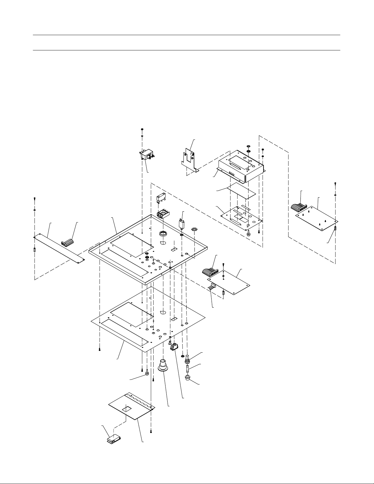
Item
No. Quantity
Dia.
Mkgs.
Part
No.
Description
Figure 14-1. Case Section w/Components (Continued)
29 134 201 STAND-OFF, PC card 8. . . . . . . . . . . . . . . . . . . . . . . . . . . . . . . . . . . . . . . . . . . . . . . . . . . . . . . . . . . . . .
30 RC10 094 593 CONNECTOR, circ 37skt rcpt 1. . . . . . . . . . . . . . . . . . . . . . . . . . . . . . . . . . . . . . . . . . . . . . . .
31 RC21 076 624 CONNECTOR, circ 4 pin rcpt 1. . . . . . . . . . . . . . . . . . . . . . . . . . . . . . . . . . . . . . . . . . . . . . . . .
32 RC8 153 884 CONNECTOR, circ 19skt rcpt 1. . . . . . . . . . . . . . . . . . . . . . . . . . . . . . . . . . . . . . . . . . . . . . . . . .
33 070 371 BLANK, snap-in nyl 1.093/1.125mtg hole black 1. . . . . . . . . . . . . . . . . . . . . . . . . . . . . . . . . . . . . . . .
To maintain the factory original performance of your equipment, use only Manufacturer’s Suggested
Replacement Parts. Model and serial number required when ordering parts from your local distributor.
Hardware is common and
not available unless listed.
1
2
9
4
5
3
8
7
6
13
14
2
10
11
12
OM-1595 Page 90
20
22
21
17
18
19
Figure 14-2. Door w/Components
15
16
15
ST-801 442-B
Page 97

Item
No. Quantity
Dia.
Mkgs.
Part
No.
Description
Figure 14-2. Door w/Components
1 DSPL1 203 663 DISPLAY, vfd dotmatrix 1x20 alphanumeric 20 pin 1. . . . . . . . . . . . . . . . . . . . . . . . . . . . . .
2 178 418 CABLE, ribbon 1. . . . . . . . . . . . . . . . . . . . . . . . . . . . . . . . . . . . . . . . . . . . . . . . . . . . . . . . . . . . . . . . . . . .
3 208 878 DOOR, cabinet 1. . . . . . . . . . . . . . . . . . . . . . . . . . . . . . . . . . . . . . . . . . . . . . . . . . . . . . . . . . . . . . . . . . . .
4 FL1 084 171 FILTER, line power 115/250V 1. . . . . . . . . . . . . . . . . . . . . . . . . . . . . . . . . . . . . . . . . . . . . . . . . . .
5 CB1 011 991 CIRCUIT BREAKER, man reset 1P 1.5A 250VAC 1. . . . . . . . . . . . . . . . . . . . . . . . . . . . . . . . .
6 154 109 PLATE, ident inner control 1. . . . . . . . . . . . . . . . . . . . . . . . . . . . . . . . . . . . . . . . . . . . . . . . . . . . . . . . . .
7 155 024 LENS, clear anti glare 1. . . . . . . . . . . . . . . . . . . . . . . . . . . . . . . . . . . . . . . . . . . . . . . . . . . . . . . . . . . . . .
8 168 337 PANEL, control inner 1. . . . . . . . . . . . . . . . . . . . . . . . . . . . . . . . . . . . . . . . . . . . . . . . . . . . . . . . . . . . . . .
9 PC8 156 623 CIRCUIT CARD ASSEMBLY, data card 1. . . . . . . . . . . . . . . . . . . . . . . . . . . . . . . . . . . . . . . . . .
PLG60 153 501 CONNECTOR & SOCKETS 1. . . . . . . . . . . . . . . . . . . . . . . . . . . . . . . . . . . . . . . . . . . . . . . . . . . . .
10 169 923 CABLE, ribbon 24posn 14.000 in 1. . . . . . . . . . . . . . . . . . . . . . . . . . . . . . . . . . . . . . . . . . . . . . . . . . . . .
11 PC9 158 160 CIRCUIT CARD ASSEMBLY, (consisting of) 1. . . . . . . . . . . . . . . . . . . . . . . . . . . . . . . . . . . . . .
DSPL2 159 063 LCD/HEADER/CAPACITORS 1. . . . . . . . . . . . . . . . . . . . . . . . . . . . . . . . . . . . . . . . . . . . . . . . . . . .
114 265 SPACER, nyl .250 OD x .115 ID x .125 lg 4. . . . . . . . . . . . . . . . . . . . . . . . . . . . . . . . . . . . . . . . . . . . . . . .
114 845 SPACER, nyl .250 OD x .115 ID x .437 lg 4. . . . . . . . . . . . . . . . . . . . . . . . . . . . . . . . . . . . . . . . . . . . . . . .
12 144 844 STAND-OFF, No. 6-32 x .875 lg 13. . . . . . . . . . . . . . . . . . . . . . . . . . . . . . . . . . . . . . . . . . . . . . . . . . . . .
13 178 492 CABLE, ribbon 20 conductor 1. . . . . . . . . . . . . . . . . . . . . . . . . . . . . . . . . . . . . . . . . . . . . . . . . . . . . . . .
14 PC7 177 333 CIRCUIT CARD ASSEMBLY, VFD switch board 1. . . . . . . . . . . . . . . . . . . . . . . . . . . . . . . . . .
15 046 432 HOLDER, fuse mintr 1. . . . . . . . . . . . . . . . . . . . . . . . . . . . . . . . . . . . . . . . . . . . . . . . . . . . . . . . . . . . . . .
16 F1 012 655 FUSE, mintr cer 10A 250V 1. . . . . . . . . . . . . . . . . . . . . . . . . . . . . . . . . . . . . . . . . . . . . . . . . . . . . . .
17 S1 153 699 SWITCH, rocker SPDT 16A 125VAC 1. . . . . . . . . . . . . . . . . . . . . . . . . . . . . . . . . . . . . . . . . . . . .
18 198 768 PUSH BUTTON, red mushroom, w/contact block 1. . . . . . . . . . . . . . . . . . . . . . . . . . . . . . . . . . . . . .
19 168 459 DOOR, access 1. . . . . . . . . . . . . . . . . . . . . . . . . . . . . . . . . . . . . . . . . . . . . . . . . . . . . . . . . . . . . . . . . . . .
20 089 099 LATCH, slide flush 1. . . . . . . . . . . . . . . . . . . . . . . . . . . . . . . . . . . . . . . . . . . . . . . . . . . . . . . . . . . . . . . . .
21 144 842 ACTUAT OR SWITCH 8. . . . . . . . . . . . . . . . . . . . . . . . . . . . . . . . . . . . . . . . . . . . . . . . . . . . . . . . . . . . . .
180 294 ACTUATOR SWITCH 2. . . . . . . . . . . . . . . . . . . . . . . . . . . . . . . . . . . . . . . . . . . . . . . . . . . . . . . . . . . . . . . . .
22 NAMEPLATE, (order by model and serial number) 1. . . . . . . . . . . . . . . . . . . . . . . . . . . . . . . . . . . . . . . . . . . . . .
To maintain the factory original performance of your equipment, use only Manufacturer’s Suggested
Replacement Parts. Model and serial number required when ordering parts from your local distributor.
Dia.
Mkgs. Quantity
Part
No.
Description
Operation Box, Remote
178 301 CASE, front bottom 1. . . . . . . . . . . . . . . . . . . . . . . . . . . . . . . . . . . . . . . . . . . . . . . . . . . . . . . . . . . . . . . . . . .
173 112 WRAPPER 1. . . . . . . . . . . . . . . . . . . . . . . . . . . . . . . . . . . . . . . . . . . . . . . . . . . . . . . . . . . . . . . . . . . . . . . . . .
NAMEPLATE, (order by model and serial number) 1. . . . . . . . . . . . . . . . . . . . . . . . . . . . . . . . . . . . . . . . . . . . . . . . .
PB2 133 001 SWITCH, PB w/red lens 1. . . . . . . . . . . . . . . . . . . . . . . . . . . . . . . . . . . . . . . . . . . . . . . . . . . . . . . . . .
S2 198 768 PUSH BUTTON, red mushroom, w/contact block 1. . . . . . . . . . . . . . . . . . . . . . . . . . . . . . . . . . . . .
PC1 179 485 CIRCUIT CARD ASSEMBLY, pendant switch 1. . . . . . . . . . . . . . . . . . . . . . . . . . . . . . . . . . . . . . . .
089 186 ACTUATOR, switch 8. . . . . . . . . . . . . . . . . . . . . . . . . . . . . . . . . . . . . . . . . . . . . . . . . . . . . . . . . . . . . . . . . . .
180 652 CONNECTORS, w/leads 1. . . . . . . . . . . . . . . . . . . . . . . . . . . . . . . . . . . . . . . . . . . . . . . . . . . . . . . . . . . . . .
073 756 STAND-OFF, 6-32 x .625 lg 5. . . . . . . . . . . . . . . . . . . . . . . . . . . . . . . . . . . . . . . . . . . . . . . . . . . . . . . . . . . .
093 551 KNOB, pointer 1. . . . . . . . . . . . . . . . . . . . . . . . . . . . . . . . . . . . . . . . . . . . . . . . . . . . . . . . . . . . . . . . . . . . . . . .
S1 111 997 SWITCH, rocker 10A 250VAC on-off 1. . . . . . . . . . . . . . . . . . . . . . . . . . . . . . . . . . . . . . . . . . . . . . . .
PB1 133 000 SWITCH, PB w/green lens 1. . . . . . . . . . . . . . . . . . . . . . . . . . . . . . . . . . . . . . . . . . . . . . . . . . . . . . . .
158 743 CONNECTOR, rect univ 039 20P/S 2 row 1. . . . . . . . . . . . . . . . . . . . . . . . . . . . . . . . . . . . . . . . . . . . . . . .
To maintain the factory original performance of your equipment, use only Manufacturer’s Suggested
Replacement Parts. Model and serial number required when ordering parts from your local distributor.
OM-1595 Page 91
Page 98

Notes
OM-1595 Page 92
Page 99

Warranty Questions?
Call
1-800-4-A-MILLER
for your local
Miller distributor.
Y our distributor also gives
you ...
Service
Y ou always get the fast,
reliable response you
need. Most replacement
parts can be in your
hands in 24 hours.
Support
Need fast answers to the
tough welding questions?
Contact your distributor.
The expertise of the
distributor and Miller is
there to help you, every
step of the way.
Effective January 1, 2002
(Equipment with a serial number preface of “LC” or newer)
This limited warranty supersedes all previous Miller warranties and is exclusive with no other
LIMITED WARRANTY – Subject to the terms and conditions
below, Miller Electric Mfg. Co., Appleton, Wisconsin, warrants
to its original retail purchaser that new Miller equipment sold
after the effective date of this limited warranty is free of defects
in material and workmanship at the time it is shipped by Miller.
THIS WARRANTY IS EXPRESSLY IN LIEU OF ALL OTHER
WARRANTIES, EXPRESS OR IMPLIED, INCLUDING THE
WARRANTIES OF MERCHANTABILITY AND FITNESS.
Within the warranty periods listed below, Miller will repair or
replace any warranted parts or components that fail due to
such defects in material or workmanship. Miller must be
notified in writing within thirty (30) days of such defect or
failure, at which time Miller will provide instructions on the
warranty claim procedures to be followed.
Miller shall honor warranty claims on warranted equipment
listed below in the event of such a failure within the warranty
time periods. All warranty time periods start on the date that
the equipment was delivered to the original retail purchaser, or
one year after the equipment is sent to a North American
distributor or eighteen months after the equipment is sent to an
International distributor.
1. 5 Years Parts – 3 Years Labor
* Original main power rectifiers
* Inverters (input and output rectifiers only)
2. 3 Years — Parts and Labor
* Transformer/Rectifier Power Sources
* Plasma Arc Cutting Power Sources
* Semi-Automatic and Automatic Wire Feeders
* Inverter Power Supplies
* Intellitig
* Engine Driven Welding Generators
(NOTE: Engines are warranted separately by
the engine manufacturer .)
3. 1 Year — Parts and Labor Unless Specified
* DS-2 Wire Feeder
* Motor Driven Guns (w/exception of Spoolmate
Spoolguns)
* Process Controllers
* Positioners and Controllers
* Automatic Motion Devices
* RFCS Foot Controls
* Induction Heating Power Sources
* Water Coolant Systems
* Flowgauge and Flowmeter Regulators (No Labor)
* HF Units
* Grids
* Maxstar 85, 140
* Spot Welders
* Load Banks
* Racks
* Running Gear/Trailers
* Plasma Cutting Torches (except APT & SAF
Models)
* Field Options
(NOTE: Field options are covered under True
Blue for the remaining warranty period of the
product they are installed in, or for a minimum of
one year — whichever is greater.)
4. 6 Months — Batteries
5. 90 Days — Parts
* MIG Guns/TIG Torches
* Induction Heating Coils and Blankets
guarantees or warranties expressed or implied.
* APT, ZIPCUT & PLAZCUT Model Plasma Cutting
Torches
* Remote Controls
* Accessory Kits
* Replacement Parts (No labor)
* Spoolmate Spoolguns
* Canvas Covers
Miller’s True Blue Limited Warranty shall not apply to:
1. Consumable components; such as contact tips,
cutting nozzles, contactors, brushes, slip rings,
relays or parts that fail due to normal wear.
(Exception: brushes, slip rings, and relays are
covered on B o b cat, Trailblazer, and Legend models.)
2. Items furnished by Miller, but manufactured by others,
such as engines or trade accessories. These items are
covered by the manufacturer’s warranty, if any.
3. Equipment that has been modified by any party other
than Miller, or equipment that has been improperly
installed, improperly operated or misused based upon
industry standards, or equipment which has not had
reasonable and necessary maintenance, or equipment
which has been used for operation outside of the
specifications for the equipment.
MILLER PRODUCTS ARE INTENDED FOR PURCHASE
AND USE BY COMMERCIAL/INDUSTRIAL USERS AND
PERSONS TRAINED AND EXPERIENCED IN THE USE
AND MAINTENANCE OF WELDING EQUIPMENT.
In the event of a warranty claim covered by this warranty, the
exclusive remedies shall be, at Miller’s option: (1) repair; or (2)
replacement; or, where authorized in writing by Miller in
appropriate cases, (3) the reasonable cost of repair or
replacement at an authorized Miller service station; or (4)
payment of or credit for the purchase price (less reasonable
depreciation bas e d u p o n a c tual use) upon return of the goods
at customer’s risk and expense. Miller’s option of repair or
replacement will be F.O.B., Factory at Appleton, Wisconsin, or
F.O.B. at a Miller authorized service facility as determined by
Miller. Therefore no compensation or reimbursement for
transportation costs of any kind will be allowed.
TO THE EXTENT PERMITTED BY LAW, THE REMEDIES
PROVIDED HEREIN ARE THE SOLE AND EXCLUSIVE
REMEDIES. I N N O EVENT SHALL MILLER BE LIABLE FOR
DIRECT, INDIRECT, SPECIAL, INCIDENTAL OR
CONSEQUENTIAL DAMAGES (INCLUDING LOSS OF
PROFIT), WHETHER BASED ON CONTRACT, TORT OR
ANY OTHER LEGAL THEORY.
ANY EXPRESS WARRANTY NOT PROVIDED HEREIN
AND ANY IMPLIED WARRANTY, GUARANTY OR
REPRESENTATION AS TO PERFORMANCE, AND ANY
REMEDY FOR BREACH OF CONTRACT TORT OR ANY
OTHER LEGAL THEORY WHICH, BUT FOR THIS
PROVISION, MIGHT ARISE BY IMPLICATION,
OPERATION OF LAW, CUSTOM OF TRADE OR COURSE
OF DEALING, INCLUDING ANY IMPLIED WARRANTY OF
MERCHANTABILITY OR FITNESS FOR PARTICULAR
PURPOSE, WITH RESPECT TO ANY AND ALL
EQUIPMENT FURNISHED BY MILLER IS EXCLUDED AND
DISCLAIMED BY MILLER.
Some states in the U.S.A. do not allow limitations of how long
an implied warranty lasts, or the exclusion of incidental,
indirect, special or consequential damages, so the above
limitation or exclusion may not apply to you. This warranty
provides specific legal rights, and other rights may be
available, but may vary from state to state.
In Canada, legislation in some provinces provides for certain
additional warranties or remedies other than as stated herein,
and to the extent that they may not be waived, the limitations
and exclusions set out above may not apply. This Limited
Warranty provides specific legal rights, and other rights may
be available, but may vary from province to province.
miller_warr 6/02
Page 100
Owner’s Record
Please complete and retain with your personal records.
Model Name Serial/Style Number
Purchase Date (Date which equipment was delivered to original customer.)
Distributor
Address
City
State Zip
For Service
Call 1-800-4-A-Miller or see our website at www.MillerWelds.com
to locate a DISTRIBUTOR or SERVICE AGENCY near you.
Always provide Model Name and Serial/Style Number.
Contact your Distributor for:
Welding Supplies and Consumables
Options and Accessories
Personal Safety Equipment
Service and Repair
Replacement Parts
Training (Schools, Videos, Books)
Technical Manuals (Servicing Information
and Parts)
Circuit Diagrams
Welding Process Handbooks
Miller Electric Mfg. Co.
An Ill inoi s Tool Works Company
1635 West Spencer Street
Appleton, WI 54914 USA
International Headquarters–USA
USA Phone: 920-735-4505 Auto-A t t ended
USA & Canada FAX: 920-735-4134
International FAX: 920-735-4125
European Headquarters –
United Kingdom
Phone: 44 (0) 1204-593493
FAX: 44 (0) 1204-598066
www.MillerWelds.com
Contact the Delivering Carrier To:
PRINTED IN USA 2002 Miller Electric Mfg. Co. 6/02
File a claim for loss or damage during
shipment.
For assistance in filing or settling claims, contact your
distributor and/or equipment manufacturer’s Transportation Department.
 Loading...