

Page 1
OM-278680G
Processes
Stick (SMAW) Welding
MIG (GMAW) Welding
Flux Cored (FCAW) Welding
TIG (GTAW) Welding
Description
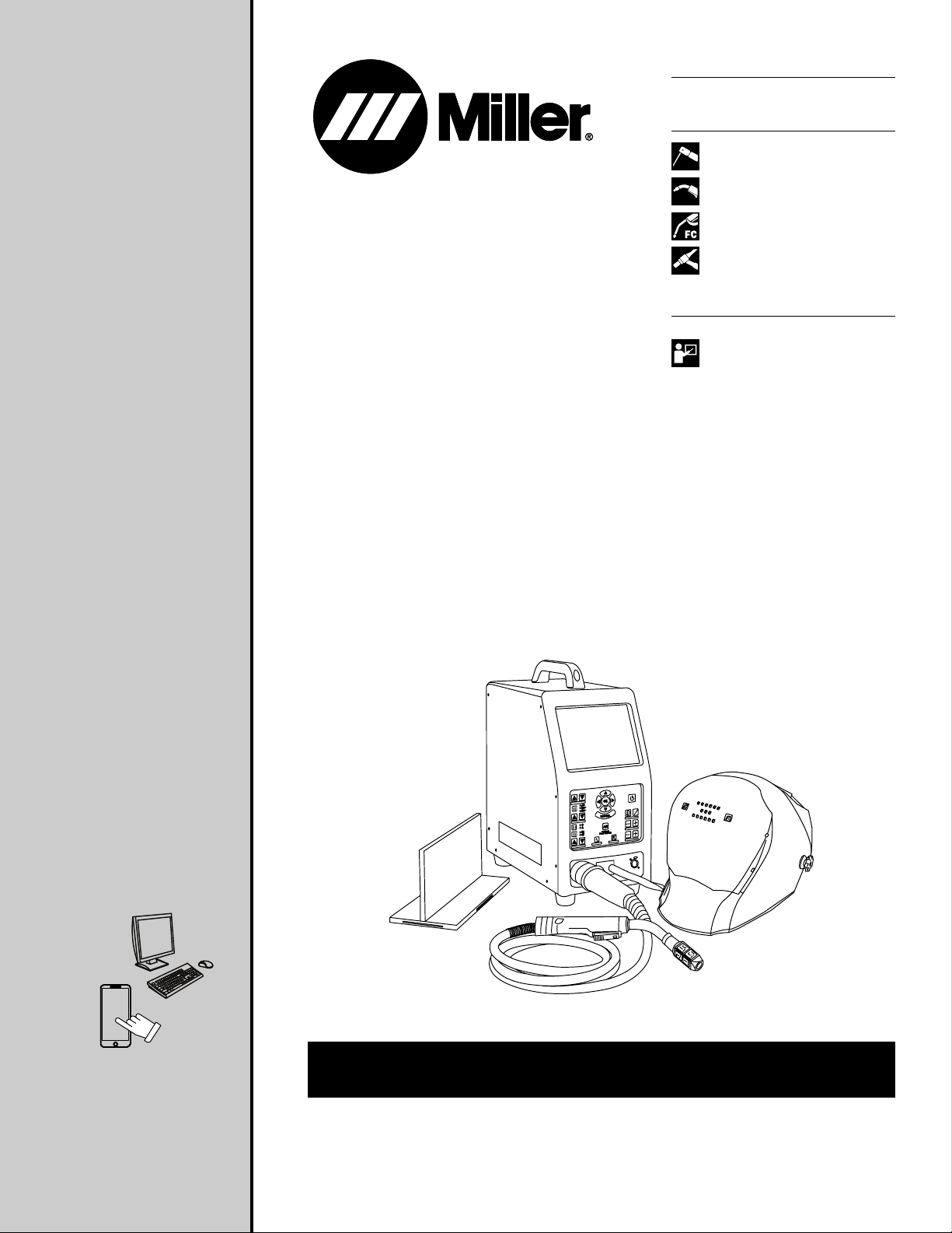
Arc Welding Training System
Augmented Arc
2023-03
®
Welding Training System
For product information,
Owner’s Manual translations,
and more, visit
www.MillerWelds.com
OWNER’S MANUAL
Page 2
From Miller to You
Thank you and congratulations on choosing Miller. Now you can get
the job done and get it done right. We know you don’t have time to do
it any other way.
That’s why when Niels Miller first started building arc welders in 1929,
he made sure his products offered long-lasting value and superior
quality. Like you, his customers couldn’t afford anything less. Miller
products had to be more than the best they could be. They had to be
the best you could buy.
Today, the people that build and sell Miller products continue the
tradition. They’re just as committed to providing equipment and
service that meets the high standards of quality and value established
in 1929.
This Owner’s Manual is designed to help you get the most out of your
Miller products. Please take time to read the Safety Precautions. They
will help you protect yourself against potential hazards on the
worksite. We’ve made installation and operation quick and easy. With
Miller, you can count on years of reliable service with proper
maintenance. And if for some reason the unit needs repair, there’s a
Troubleshooting section that will help you figure out what the problem
is, and our extensive service network is there to help fix the problem.
Working as hard as you do −
every power source from
Miller is backed by the most
hassle-free warranty in the
business.
Warranty and maintenance information for your particular model are
also provided.
Miller Electric manufactures a full line of
welders and welding-related equipment. For
information on other quality Miller products,
contact your local Miller distributor to receive
the latest full line catalog or individual
specification sheets. To locate your nearest
distributor or service agency call
1-800-4-A-Miller, or visit us at www.MillerWelds.com on the web.
Page 3

TABLE OF CONTENTS
SECTION 1 – SAFETY PRECAUTIONS – READ BEFORE USING. . . . . . . . . . . . . . . . . . . . . . . . . . . . . . . . . . . . . . . . . . . . . . . . . . . . . . . . . . . . . . . . . . 1
1-1 Symbol Usage . . . . . . . . . . . . . . . . . . . . . . . . . . . . . . . . . . . . . . . . . . . . . . . . . . . . . . . . . . . . . . . . . . . . . . . . . . . . . . . . . . . . . . . . . . . . . . . . . . . . . . 1
1-2 Welding Training System Hazards . . . . . . . . . . . . . . . . . . . . . . . . . . . . . . . . . . . . . . . . . . . . . . . . . . . . . . . . . . . . . . . . . . . . . . . . . . . . . . . . . . . . . 1
1-3 California Proposition 65 Warnings . . . . . . . . . . . . . . . . . . . . . . . . . . . . . . . . . . . . . . . . . . . . . . . . . . . . . . . . . . . . . . . . . . . . . . . . . . . . . . . . . . . . 1
1-4 Principal Safety Standards. . . . . . . . . . . . . . . . . . . . . . . . . . . . . . . . . . . . . . . . . . . . . . . . . . . . . . . . . . . . . . . . . . . . . . . . . . . . . . . . . . . . . . . . . . . . 1
SECTION 2 – CONSIGNES DE SÉCURITÉ - LIRE AVANT UTILISATION. . . . . . . . . . . . . . . . . . . . . . . . . . . . . . . . . . . . . . . . . . . . . . . . . . . . . . . . . . . . 2
2-1 Symboles utilisés. . . . . . . . . . . . . . . . . . . . . . . . . . . . . . . . . . . . . . . . . . . . . . . . . . . . . . . . . . . . . . . . . . . . . . . . . . . . . . . . . . . . . . . . . . . . . . . . . . . . 2
2-2 Dangers liés au système de formation en soudure . . . . . . . . . . . . . . . . . . . . . . . . . . . . . . . . . . . . . . . . . . . . . . . . . . . . . . . . . . . . . . . . . . . . . . . 2
2-3 Proposition californienne 65 Avertissements . . . . . . . . . . . . . . . . . . . . . . . . . . . . . . . . . . . . . . . . . . . . . . . . . . . . . . . . . . . . . . . . . . . . . . . . . . . . 2
2-4 Principales normes de sécurité . . . . . . . . . . . . . . . . . . . . . . . . . . . . . . . . . . . . . . . . . . . . . . . . . . . . . . . . . . . . . . . . . . . . . . . . . . . . . . . . . . . . . . . . 2
SECTION 3 – DEFINITIONS . . . . . . . . . . . . . . . . . . . . . . . . . . . . . . . . . . . . . . . . . . . . . . . . . . . . . . . . . . . . . . . . . . . . . . . . . . . . . . . . . . . . . . . . . . . . . . . . . . . 4
3-1 Miscellaneous Symbols And Definitions . . . . . . . . . . . . . . . . . . . . . . . . . . . . . . . . . . . . . . . . . . . . . . . . . . . . . . . . . . . . . . . . . . . . . . . . . . . . . . . . 4
SECTION 4 – SPECIFICATIONS . . . . . . . . . . . . . . . . . . . . . . . . . . . . . . . . . . . . . . . . . . . . . . . . . . . . . . . . . . . . . . . . . . . . . . . . . . . . . . . . . . . . . . . . . . . . . . . 5
4-1 Introduction. . . . . . . . . . . . . . . . . . . . . . . . . . . . . . . . . . . . . . . . . . . . . . . . . . . . . . . . . . . . . . . . . . . . . . . . . . . . . . . . . . . . . . . . . . . . . . . . . . . . . . . . . 5
4-2 System Features And Benefits . . . . . . . . . . . . . . . . . . . . . . . . . . . . . . . . . . . . . . . . . . . . . . . . . . . . . . . . . . . . . . . . . . . . . . . . . . . . . . . . . . . . . . . . 5
4-3 AugmentedArc Complete Package . . . . . . . . . . . . . . . . . . . . . . . . . . . . . . . . . . . . . . . . . . . . . . . . . . . . . . . . . . . . . . . . . . . . . . . . . . . . . . . . . . . . 5
4-4 Serial Number And Rating Label Location . . . . . . . . . . . . . . . . . . . . . . . . . . . . . . . . . . . . . . . . . . . . . . . . . . . . . . . . . . . . . . . . . . . . . . . . . . . . . . 5
4-5 Unit Specifications. . . . . . . . . . . . . . . . . . . . . . . . . . . . . . . . . . . . . . . . . . . . . . . . . . . . . . . . . . . . . . . . . . . . . . . . . . . . . . . . . . . . . . . . . . . . . . . . . . . 6
4-6 Software Licensing Agreement . . . . . . . . . . . . . . . . . . . . . . . . . . . . . . . . . . . . . . . . . . . . . . . . . . . . . . . . . . . . . . . . . . . . . . . . . . . . . . . . . . . . . . . . 6
4-7 Information About Default Weld Parameters And Settings . . . . . . . . . . . . . . . . . . . . . . . . . . . . . . . . . . . . . . . . . . . . . . . . . . . . . . . . . . . . . . . . . 7
4-8 Environmental Specifications . . . . . . . . . . . . . . . . . . . . . . . . . . . . . . . . . . . . . . . . . . . . . . . . . . . . . . . . . . . . . . . . . . . . . . . . . . . . . . . . . . . . . . . . . 7
SECTION 5 – INSTALLATION. . . . . . . . . . . . . . . . . . . . . . . . . . . . . . . . . . . . . . . . . . . . . . . . . . . . . . . . . . . . . . . . . . . . . . . . . . . . . . . . . . . . . . . . . . . . . . . . . . 8
5-1 Selecting A Location . . . . . . . . . . . . . . . . . . . . . . . . . . . . . . . . . . . . . . . . . . . . . . . . . . . . . . . . . . . . . . . . . . . . . . . . . . . . . . . . . . . . . . . . . . . . . . . . . 8
5-2 Simulator Components. . . . . . . . . . . . . . . . . . . . . . . . . . . . . . . . . . . . . . . . . . . . . . . . . . . . . . . . . . . . . . . . . . . . . . . . . . . . . . . . . . . . . . . . . . . . . . . 9
5-3 Installing The Training System—Standalone Configuration . . . . . . . . . . . . . . . . . . . . . . . . . . . . . . . . . . . . . . . . . . . . . . . . . . . . . . . . . . . . . . . 10
5-4 Installing The Training System With Optional Controller - Classroom Configuration . . . . . . . . . . . . . . . . . . . . . . . . . . . . . . . . . . . . . . . . . . 11
5-5 Connecting Simulator To An External Monitor . . . . . . . . . . . . . . . . . . . . . . . . . . . . . . . . . . . . . . . . . . . . . . . . . . . . . . . . . . . . . . . . . . . . . . . . . . 12
5-6 Assembling AR MIG Gun . . . . . . . . . . . . . . . . . . . . . . . . . . . . . . . . . . . . . . . . . . . . . . . . . . . . . . . . . . . . . . . . . . . . . . . . . . . . . . . . . . . . . . . . . . . . 12
5-7 Assembling AR TIG Torch . . . . . . . . . . . . . . . . . . . . . . . . . . . . . . . . . . . . . . . . . . . . . . . . . . . . . . . . . . . . . . . . . . . . . . . . . . . . . . . . . . . . . . . . . . . 13
5-8 Assembling AR Stick Electrode/TIG Filler Rod . . . . . . . . . . . . . . . . . . . . . . . . . . . . . . . . . . . . . . . . . . . . . . . . . . . . . . . . . . . . . . . . . . . . . . . . . . 14
5-9 AR Stick Electrode, MIG Gun, And TIG Torch . . . . . . . . . . . . . . . . . . . . . . . . . . . . . . . . . . . . . . . . . . . . . . . . . . . . . . . . . . . . . . . . . . . . . . . . . . 15
5-10 AR Configurable Workpieces . . . . . . . . . . . . . . . . . . . . . . . . . . . . . . . . . . . . . . . . . . . . . . . . . . . . . . . . . . . . . . . . . . . . . . . . . . . . . . . . . . . . . . . . 16
5-11 AR Welding Helmet . . . . . . . . . . . . . . . . . . . . . . . . . . . . . . . . . . . . . . . . . . . . . . . . . . . . . . . . . . . . . . . . . . . . . . . . . . . . . . . . . . . . . . . . . . . . . . . . . 17
5-12 Making Helmet Adjustments . . . . . . . . . . . . . . . . . . . . . . . . . . . . . . . . . . . . . . . . . . . . . . . . . . . . . . . . . . . . . . . . . . . . . . . . . . . . . . . . . . . . . . . . . 17
5-13 Installing Optional Magnifying Lens . . . . . . . . . . . . . . . . . . . . . . . . . . . . . . . . . . . . . . . . . . . . . . . . . . . . . . . . . . . . . . . . . . . . . . . . . . . . . . . . . . . 18
5-14 Connecting Weld Cables . . . . . . . . . . . . . . . . . . . . . . . . . . . . . . . . . . . . . . . . . . . . . . . . . . . . . . . . . . . . . . . . . . . . . . . . . . . . . . . . . . . . . . . . . . . . 19
SECTION 6 – SYSTEM CONTROLS AND COMPONENTS . . . . . . . . . . . . . . . . . . . . . . . . . . . . . . . . . . . . . . . . . . . . . . . . . . . . . . . . . . . . . . . . . . . . . . . 20
6-1 Simulator Controls. . . . . . . . . . . . . . . . . . . . . . . . . . . . . . . . . . . . . . . . . . . . . . . . . . . . . . . . . . . . . . . . . . . . . . . . . . . . . . . . . . . . . . . . . . . . . . . . . . 20
SECTION 7 – OPERATION . . . . . . . . . . . . . . . . . . . . . . . . . . . . . . . . . . . . . . . . . . . . . . . . . . . . . . . . . . . . . . . . . . . . . . . . . . . . . . . . . . . . . . . . . . . . . . . . . . . 21
7-1 Equipment Setup. . . . . . . . . . . . . . . . . . . . . . . . . . . . . . . . . . . . . . . . . . . . . . . . . . . . . . . . . . . . . . . . . . . . . . . . . . . . . . . . . . . . . . . . . . . . . . . . . . . 21
7-2 Getting Started. . . . . . . . . . . . . . . . . . . . . . . . . . . . . . . . . . . . . . . . . . . . . . . . . . . . . . . . . . . . . . . . . . . . . . . . . . . . . . . . . . . . . . . . . . . . . . . . . . . . . 22
SECTION 8 – ADMINISTRATOR SYSTEM SETTINGS . . . . . . . . . . . . . . . . . . . . . . . . . . . . . . . . . . . . . . . . . . . . . . . . . . . . . . . . . . . . . . . . . . . . . . . . . . . 37
8-1 Accessing Administrator Home Screen . . . . . . . . . . . . . . . . . . . . . . . . . . . . . . . . . . . . . . . . . . . . . . . . . . . . . . . . . . . . . . . . . . . . . . . . . . . . . . . . 37
8-2 Changing System Configuration . . . . . . . . . . . . . . . . . . . . . . . . . . . . . . . . . . . . . . . . . . . . . . . . . . . . . . . . . . . . . . . . . . . . . . . . . . . . . . . . . . . . . . 37
8-3 Software Updates . . . . . . . . . . . . . . . . . . . . . . . . . . . . . . . . . . . . . . . . . . . . . . . . . . . . . . . . . . . . . . . . . . . . . . . . . . . . . . . . . . . . . . . . . . . . . . . . . . 40
8-4 Troubleshooting. . . . . . . . . . . . . . . . . . . . . . . . . . . . . . . . . . . . . . . . . . . . . . . . . . . . . . . . . . . . . . . . . . . . . . . . . . . . . . . . . . . . . . . . . . . . . . . . . . . . 41
8-5 Check Components. . . . . . . . . . . . . . . . . . . . . . . . . . . . . . . . . . . . . . . . . . . . . . . . . . . . . . . . . . . . . . . . . . . . . . . . . . . . . . . . . . . . . . . . . . . . . . . . . 41
8-6 Cameras . . . . . . . . . . . . . . . . . . . . . . . . . . . . . . . . . . . . . . . . . . . . . . . . . . . . . . . . . . . . . . . . . . . . . . . . . . . . . . . . . . . . . . . . . . . . . . . . . . . . . . . . . . 44
8-7 Video Device Settings . . . . . . . . . . . . . . . . . . . . . . . . . . . . . . . . . . . . . . . . . . . . . . . . . . . . . . . . . . . . . . . . . . . . . . . . . . . . . . . . . . . . . . . . . . . . . . . 50
8-8 Distance Learning Mode . . . . . . . . . . . . . . . . . . . . . . . . . . . . . . . . . . . . . . . . . . . . . . . . . . . . . . . . . . . . . . . . . . . . . . . . . . . . . . . . . . . . . . . . . . . . 53
SECTION 9 – USING THE TEACHER SOFTWARE . . . . . . . . . . . . . . . . . . . . . . . . . . . . . . . . . . . . . . . . . . . . . . . . . . . . . . . . . . . . . . . . . . . . . . . . . . . . . . 57
9-1 Installing The Teacher Software Program . . . . . . . . . . . . . . . . . . . . . . . . . . . . . . . . . . . . . . . . . . . . . . . . . . . . . . . . . . . . . . . . . . . . . . . . . . . . . . 57
9-2 Instructional Help Videos . . . . . . . . . . . . . . . . . . . . . . . . . . . . . . . . . . . . . . . . . . . . . . . . . . . . . . . . . . . . . . . . . . . . . . . . . . . . . . . . . . . . . . . . . . . . 60
9-3 Using The Teacher Software . . . . . . . . . . . . . . . . . . . . . . . . . . . . . . . . . . . . . . . . . . . . . . . . . . . . . . . . . . . . . . . . . . . . . . . . . . . . . . . . . . . . . . . . . 61
9-4 Module Management . . . . . . . . . . . . . . . . . . . . . . . . . . . . . . . . . . . . . . . . . . . . . . . . . . . . . . . . . . . . . . . . . . . . . . . . . . . . . . . . . . . . . . . . . . . . . . . 66
9-5 Course Management . . . . . . . . . . . . . . . . . . . . . . . . . . . . . . . . . . . . . . . . . . . . . . . . . . . . . . . . . . . . . . . . . . . . . . . . . . . . . . . . . . . . . . . . . . . . . . . 74
9-6 Reviewing Student Activity And Results . . . . . . . . . . . . . . . . . . . . . . . . . . . . . . . . . . . . . . . . . . . . . . . . . . . . . . . . . . . . . . . . . . . . . . . . . . . . . . . 77
9-7 Account And Settings . . . . . . . . . . . . . . . . . . . . . . . . . . . . . . . . . . . . . . . . . . . . . . . . . . . . . . . . . . . . . . . . . . . . . . . . . . . . . . . . . . . . . . . . . . . . . . . 81
SECTION 10 – ROUTINE MAINTENANCE AND STORAGE . . . . . . . . . . . . . . . . . . . . . . . . . . . . . . . . . . . . . . . . . . . . . . . . . . . . . . . . . . . . . . . . . . . . . . 83
SECTION 11 – TROUBLESHOOTING TABLE. . . . . . . . . . . . . . . . . . . . . . . . . . . . . . . . . . . . . . . . . . . . . . . . . . . . . . . . . . . . . . . . . . . . . . . . . . . . . . . . . . . 84
SECTION 12 – PARTS LIST . . . . . . . . . . . . . . . . . . . . . . . . . . . . . . . . . . . . . . . . . . . . . . . . . . . . . . . . . . . . . . . . . . . . . . . . . . . . . . . . . . . . . . . . . . . . . . . . . . 85
Page 4

Page 5
SECTION 1 – SAFETY PRECAUTIONS – READ BEFORE USING
Protect yourself and others from injury—read, follow, and save these important safety precautions and operating instructions.
1-1. Symbol Usage
DANGER! – Indicates a hazardous situation which, if not
avoided, will result in death or serious injury. The possible
hazards are shown in the adjoining symbols or explained
in the text.
Indicates a hazardous situation which, if not avoided,
could result in death or serious injury. The possible hazards are shown in the adjoining symbols or explained in
the text.
NOTICE – Indicates statements not related to personal injury.
Indicates special instructions.
F
1-2. Welding Training System Hazards
The symbols shown below are used throughout this manual
to call attention to and identify possible hazards. When you
see the symbol, watch out, and follow the related instructions to avoid the hazard. The safety information given below is only a summary of the more complete safety
information found in the Principal Safety Standards. Read
and follow all Safety Standards.
Only qualified persons should install, operate, maintain,
and repair this equipment. A qualified person is defined as
one who, by possession of a recognized degree, certificate,
or professional standing, or who by extensive knowledge,
training and experience, has successfully demonstrated the
ability to solve or resolve problems relating to the subject
matter, the work, or the project and has received safety
training to recognize and avoid the hazards involved.
READ INSTRUCTIONS.
l Read and follow all labels and the Owner’s Manual
carefully before installing, operating, or servicing
unit. Read the safety information at the beginning
of the manual and in each section.
l Use only genuine replacement parts from the manufacturer.
l Perform installation, maintenance, and service according to the
Owner’s Manuals, industry standards, and national, state, and local codes.
l Do not repair, modify, or disassemble the training system or use
with parts or accessories not supplied by the manufacturer. Use
only approved components and accessories from the
manufacturer.
l Be sure all hardware is properly tightened.
This group of symbols means Warning! Watch Out! ELECTRIC
SHOCK, MOVING PARTS, and HOT PARTS hazards. Consult
symbols and related instructions below for necessary actions to
avoid these hazards.
l Do not use the training system until you are sure it is correctly as-
sembled and working properly.
l Before each use, inspect the training system for damage and veri-
fy it is secure and installed properly.
l Use the training system only as specified in the manual.
ELECTRIC SHOCK can kill.
Touching live electrical parts can cause fatal
shocks or severe burns.
l Do not touch live electrical parts.
l Disconnect input power before installing or servicing this
equipment.
l Keep cords dry, free of oil and grease, and protected from hot met-
al and sparks.
l Frequently inspect input power cord and ground conductor for
damage or bare wiring — replace immediately if damaged — bare
wiring can kill.
l Use only well-maintained equipment. Repair or replace damaged
parts at once. Maintain unit according to the manual.
l Keep all panels and covers securely in place.
l Do not use the training system during an electrical storm. Turn off
equipment and disconnect input power until risk of lightning has
passed.
l Always verify the supply ground — check and be sure that cord
plug is connected to a properly grounded receptacle outlet.
l Do not use equipment in damp or wet conditions.
1-3. California Proposition 65 Warnings
WARNING – Cancer and Reproductive Harm — www.
P65Warnings.ca.gov.
1-4. Principal Safety Standards
Safety Requirements for Electrical Equipment for Measurement, Control, and Laboratory Use — Part 1: General requirements, CAN/CSA
Standard C22.2 No. 61010-1-12, from Canadian Standards Association. Website: www.csagroup.org.
Audio/Video, Information And Communication Technology Equipment
- Part 1: Safety Requirements, CSA C22.2#62368-1:2014 Ed.2 from
Canadian Standards Association. Website: www.csagroup.org.
Audio/Video, Information And Communication Technology Equipment
- Part 1: Safety Requirements, UL 62368-1:2014 Ed.2 from Under-
writers’ Laboratories. Website: www.ul.com.
AugArc 2022–01
OM-278680 Page 1
Page 6
SECTION 2 – CONSIGNES DE SÉCURITÉ - LIRE AVANT
UTILISATION
Pour écarter les risques de blessure pour vous-même et pour autrui — lire, appliquer et ranger en lieu sûr ces consignes relatives
aux précautions de sécurité et au mode opératoire.
2-1. Symboles utilisés
DANGER! – Indique une situation dangereuse qui si on l’évite pas peut donner la mort ou des blessures graves. Les
dangers possibles sont montrés par les symboles joints
ou sont expliqués dans le texte.
Indique une situation dangereuse qui si on l’évite pas peut
donner la mort ou des blessures graves. Les dangers possibles sont montrés par les symboles joints ou sont expliqués dans le texte.
AVIS – Indique des déclarations pas en relation avec des blessures
personnelles.
Indique des instructions spécifiques.
F
2-2. Dangers liés au système de formation en soudure
Les symboles représentés ci-dessous sont utilisés dans ce
manuel pour attirer l’attention et identifier les dangers possibles. En présence de ce symbole, prendre garde et suivre
les instructions afférentes pour éviter tout risque. Les
consignes de sécurité présentées ci-après ne font que résumer l’information contenue dans les Normes de sécurité
principales. Lire et suivre toutes les Normes de sécurité.
L’installation, l’utilisation, l’entretien et les réparations ne
doivent être confiés qu’à des personnes qualifiées. Une personne qualifiée est définie comme celle qui, par la possession d’un diplôme reconnu, d’un certificat ou d’un statut
professionnel, ou qui, par une connaissance, une formation
et une expérience approfondies, a démontré avec succès sa
capacité à résoudre les problèmes liés à la tâche, le travail
ou le projet et a reçu une formation en sécurité afin de reconnaître et d’éviter les risques inhérents.
LIRE LES INSTRUCTIONS.
l Lire et appliquer les instructions sur les étiquettes
et le Mode d’emploi avant l’installation, l’utilisation
ou l’entretien de l’appareil. Lire les informations de
section.
l N’utiliser que les pièces de rechange recommandées par le
constructeur.
l Effectuer l’installation, l’entretien et toute intervention selon les
manuels d’utilisateurs, les normes nationales, provinciales et de
l’industrie, ainsi que les codes municipaux.
l Ne pas réparer, modifier ou démonter le système de formation, et
ne pas l’utiliser avec des pièces ou accessoires non fournis par le
fabricant. Utiliser uniquement des composants et accessoires approuvés par le fabricant.
l S’assurer que toute la quincaillerie est bien serrée.
l Ne pas utiliser le système de formation avant d’être certain qu’il
est bien monté et qu’il fonctionne correctement.
sécurité au début du manuel et dans chaque
Ce groupe de symboles veut dire Avertissement! Attention! DANGER DE CHOC ELECTRIQUE, PIECES EN MOUVEMENT, et PIECES CHAUDES. Reportez-vous aux symboles et aux directives cidessous afin de connaître les mesures à prendre pour éviter tout
danger.
l Avant chaque utilisation, inspecter le système de formation pour
déceler tout signe de dommage et s’assurer qu’il est bien installé
et maintenu correctement.
l Utiliser le système de formation seulement conformément au
manuel.
UNE DÉCHARGE ÉLECTRIQUE peut
entraîner la mort.
Tout contact avec des pièces électriques sous tension peut causer un choc mortel ou des brûlures
graves.
l Ne pas toucher aux pièces électriques sous tension.
l Couper le courant avant d’installer ou de faire l’entretien de cet
équipement.
l En effectuant les raccordements d’entrée, fixer d’abord le conduc-
teur de mise à la terre approprié et contre-vérifier les connexions.
l Les câbles doivent être exempts d’humidité, d’huile et de graisse;
protégez-les contre les étincelles et les pièces métalliques
chaudes.
l N’utiliser qu’un matériel en bon état. Réparer ou remplacer sur-le-
champ les pièces endommagées. Entretenir l’appareil conformément à ce manuel.
l Maintenir solidement en place tous les panneaux latéraux et les
capots.
l Ne pas utiliser le système de formation pendant un orage élec-
trique. Mettre l’équipement hors tension et débrancher l’alimentation électrique jusqu’à ce que soit éliminé le risque d’éclairs.
l Toujours vérifier la terre du cordon d’alimentation - Vérifier et s’as-
surer que la fiche du cordon est raccordée à une prise correctement mise à la terre.
l Ne pas utiliser l’équipement en conditions humides ou mouillées.
2-3. Proposition californienne 65 Avertissements
AVERTISSEMENT – Cancer et troubles de la reproduction —
www.P65Warnings.ca.gov.
2-4. Principales normes de sécurité
Safety Requirements for Electrical Equipment for Measurement,
Control, and Laboratory Use — Part 1: General requirements, CAN/
CSA Standard C22.2 No. 61010-1-12, from Canadian Standards Association. Website: www.csagroup.org.
OM-278680 Page 2
Audio/Video, Information And Communication Technology Equipment
- Part 1: Safety Requirements, CSA C22.2#62368-1:2014 Ed.2 from
Canadian Standards Association. Website: www.csagroup.org.
Page 7

Audio/Video, Information And Communication Technology Equipment
- Part 1: Safety Requirements, UL 62368-1:2014 Ed.2 from Underwri-
ters’ Laboratories. Website: www.ul.com.
AugArc_fre 2022–01
OM-278680 Page 3
Page 8
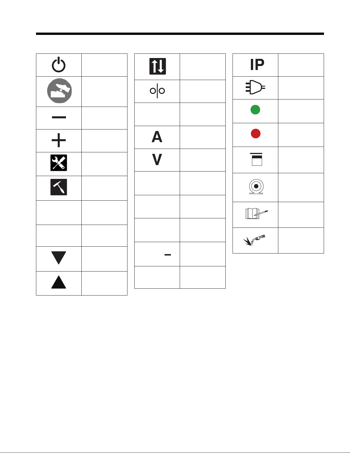
SECTION 3 – DEFINITIONS
SECTION 1 − DEFINITIONS
Power On/Off
TIG Foot Pedal
Enabled
Change Transfer
Mode
Wire Feed
AC
Alternating Current
IP
Internal Protection
Rating
SECTION 1 − DEFINITIONS
Power On/Off
TIG Foot Pedal
Enabled
Decrease
Increase
Settings
Change Transfer
Mode
Wire Feed
AR
Augmented Reality
A
Amperage
V
Voltage
AC
Alternating Current
IP
Internal Protection
Rating
Input Plug And
Cord
Connected To
Network
Disconnected
From Network
SECTION 1 DEFINITIONS
Power On/Off
TIG Foot Pedal
Enabled
Decrease
Increase
Settings
Clean Slag
Ch
ange Transfer
Mode
Wi
re Feed
AR
Augmented Reality
A
Amperage
V
Voltage
2T
Press To Start
Weld; Release To
Stop Weld
AC
Alternating Current
IP
Internal Protection
Rating
Input Plug
And
Cord
Connec
ted To
Network
Disconnected
From Network
Connected And
Seeing Theory
SECTION 1 DEFINITIONS
Power On/Off
TIG Foot Pedal
Enabled
Decrease
Increase
Settings
Clean Slag
Pass
Change Transfer
Mode
Wire Feed
AR
Augmented Reality
A
Amperage
V
Voltage
2T
Press To Start
Weld; Release To
Stop Weld
4T
Press And
Release To Start
Weld; Press And
Release To Stop
Weld
AC
Alternating Current
IP
Internal Protection
Rating
Input Plug And
Cord
Connected To
Network
Disconnected
From Network
Connected And
Seeing Theory
Connected And
Analyzing An
Exercise
SECTION 1 DEFINITIONS
Power On/Off
TIG Foot Pedal
Enabled
Decrease
I
ncrease
Se
ttings
Clean Slag
Pass
X
Fail
Change Transfer
M
ode
Wire Feed
AR
Augmented Reality
A
Amperage
V
V
oltage
2T
Press To Start
Weld; Release To
Stop Weld
4T
Press And
Release To Start
Weld; Press And
Release To Stop
Weld
DC+
DC Electrode
Positive
AC
Alternating Current
IP
Internal Protection
Rating
I
nput Plug And
C
ord
Connected To
Ne
twork
Disconnected
F
rom Network
Connected And
Seeing Theory
Connected And
Analyzing An
Exercise
Connected And
Doing A Quiz
SECTION 1 DEFINITIONS
Power On/Off
TIG Foot Pedal
Enabled
Decrease
Increase
Settings
Clean Slag
Pass
X
Fail
Down
Change Transfer
Mode
Wire Feed
AR
Augmented Reality
A
Amperage
V
Voltage
2T
Press To Start
Weld; Release To
Stop Weld
4T
Press And
Release To Start
Weld; Press And
Release To Stop
Weld
DC+
DC Electrode
Positive
DC
DC Electrode
Negative
AC
Alternating Current
IP
Internal Protection
Rating
Input Plug And
Cord
Connected To
Network
Disconnected
From Network
Connected And
Seeing Theory
Connected And
Analyzing An
Exercise
Connected And
Doing A Quiz
Connected And
Performing An
Exercise
SECTION 1 DEFINITIONS
Power On/Off
TIG Foot Pedal
Enabled
Decrease
Increase
Settings
Clean Slag
Pass
X
Fail
Down
Up
Change Transfer
Mode
Wire Feed
AR
Augmented Reality
A
Amperage
V
Voltage
2T
Press To Start
Weld; Release To
Stop Weld
4T
Press And
Release To Start
Weld; Press And
Release To Stop
Weld
DC+
DC Electrode
Positive
DC
DC Electrode
Negative
AC
Alternating Current
IP
Internal Protection
Rating
Input Plug And
Cord
Connected To
Network
Disconnected
From Network
Connected And
Seeing Theory
Connected And
Analyzing An
Exercise
Connected And
Doing A Quiz
Connected And
Performing An
Exercise
Change Transfer
Mode
AC
Alternating Current
Change Transfer
Mode
Wire Feed
AR
Augmented Reality
AC
Alternating Current
IP
Internal Protection
Rating
Input Plug And
Cord
Change Transfer
Mode
Wir
e Feed
AR
Augmented Reality
A
Amperage
V
Voltage
2T
Press To Start
Wel
d; Release To
Stop Weld
AC
Alt
ernating Current
IP
Internal Protection
Rating
Input Plug And
Cor
d
Connect
ed To
Network
Disconnected
From Network
Connected And
Seeing
Theory
Change Transfer
Mode
Wire Feed
AR
Augmented Reality
A
Amperage
V
Voltage
2T
Press To Start
Weld; Release To
Stop Weld
4T
Press And
Release To Start
Weld; Press And
Release To Stop
AC
Alternating Current
IP
Internal Protection
Rating
Input Plug And
Cord
Connected To
Network
Disconnected
From Network
Connected And
Seeing Theory
Connected And
Analyzing An
Exercise
Change Transfer
Mode
Wire Feed
AR
Augmented Reality
A
Amperage
V
Voltage
2T
Press To Start
Weld; Release To
Stop Weld
4T
Press And
Release To Start
Weld; Press And
Release To Stop
Weld
DC+
DC Electrode
Positive
AC
Alternating Current
IP
Internal Protection
Rating
Input Plug And
Cord
Connected To
Network
Disconnected
From Network
Connected And
Seeing Theory
Connected And
Analyzing An
Exercise
Connected And
Doing A Quiz
Change Transfer
Mode
Wire Feed
AR
Augmented Reality
A
Amperage
V
Voltage
2T
Press To Start
Weld; Release To
Stop Weld
4T
Press And
Release To Start
Weld; Press And
Release To Stop
Weld
DC+
DC Electrode
Positive
DC
DC Electrode
Negative
AC
Alternating Current
IP
Internal Protection
Rating
Input Plug And
Cord
Connected To
Network
Disconnected
From Network
Connected And
Seeing Theory
Connected And
Analyzing An
Exercise
Connected And
Doing A Quiz
Connected And
Performing An
Exercise
AC
Alternating Current
AC
Alternating Current
IP
Internal Protection
Rating
Input Plug And
Cord
Connected To
Network
AC
Alternating Current
IP
Int
ernal Protection
Rating
Input Plug And
Cord
Connected To
Network
Disconnected
Fro
m Network
AC
A
lternating Current
IP
Internal Protection
Rating
Input Plug And
C
ord
Connected To
Network
Disconnected
From Network
Connected And
Seeing Theory
AC
Alternating Current
IP
Internal Protection
Rating
Input Plug And
Cord
Connected To
Network
Disconnected
From Network
Connected And
Seeing Theory
Connected And
Analyzing An
Exercise
AC
Alternating Current
IP
Internal Protection
Rating
Input Plug And
Cord
Connected To
Network
Disconnected
From Network
Connected And
Seeing Theory
Connected And
Analyzing An
Exercise
Connected And
Doing A Quiz
AC
Alternating Current
IP
Internal Protection
Rating
Input Plug And
Cord
Connected To
Network
Disconnected
From Network
Connected And
Seeing Theory
Connected And
Analyzing An
Exercise
Connected And
Doing A Quiz
Connected And
Performing An
Exercise
3-1. Miscellaneous Symbols And Definitions
Power On/Off
TIG Foot Pedal
Enabled
Decrease
Increase
Change Transfer
Wire Feed
Augmented Reality
Amperage
Settings
Clean Slag
Pass
Fail
Down
Up
Press To Start
Weld; Release To
Stop Weld
Press And Release
To Start Weld;
Press And Release
To Stop Weld
DC Electrode
Positive
DC Electrode
Negative
Alternating Current
Mode
Voltage
Internal Protection
Rating
Input Plug And Cord
Connected To
Network
Disconnected From
Network
Connected And
Seeing Theory
Connected And Analyzing An Exercise
Connected And
Doing A Quiz
Connected And Performing An Exercise
OM-278680 Page 4
Page 9
SECTION 4 – SPECIFICATIONS
9
10
11
12
4-1. Introduction
The AugmentedArc is an augmented reality (AR) welding training system that provides the new student or the experienced welder the opportunity to develop, enhance, or verify their welding abilities through an interactive, simulated welding process on a variety of weld joint configurations. This product is designed to help welding students acquire the necessary welding knowledge, capacities, abilities, welding sensations and
skills, thereby saving the time and money normally spent training in a live welding situation. It is an educational solution to help both students
and trainers improve their learning experience and enhance results and qualifications. The system can be installed as a standalone or classroom
configuration.
After the AugmentedArc system is installed, the user turns on the training system, selects the desired welding assignment, puts on the augmented reality (AR) welding helmet and welding gloves (welding gloves are recommended to simulate a live welding experience), and begins
the simulated welding activity. The cameras and AR markers convey the weld data (gun angles, gun speed, contact tip to work distance [CTWD],
aim) to the system microprocessor, which compares it to the specified weld parameters of the assignment selected. The system evaluates the
weld data and grades the student’s performance.
The AugmentedArc instruction is complementary to training with live welding equipment. To complete their welding training, students should also
practice their acquired skills by welding under the supervision of qualified persons in a safe welding environment.
NOTICE – Do not install or use the Augmented Arc in the same area as live welding equipment.
4-2. System Features And Benefits
l Advanced computer simulation techniques using artificial vision technology create a realistic welding environment.
l Teacher software allows the instructor to adapt their training programs to the AugmentedArc system. The instructor can manage and moni-
tor student activity and progress from a PC (personal computer) (see Section 9).
l Analysis mode allows all of the welding exercises performed in the simulator to be visualized, providing detailed results of all of the welding
parameters.
l System allows for remote maintenance and software updates, and is adaptable to meet specific training requirements.
l The system configuration can be installed as a standalone or classroom application. The standalone application includes a simulator and a
router, and all of the information is saved on the unit. The classroom application can include multiple simulators, a router, and a controller.
All of the information is saved on the controller.
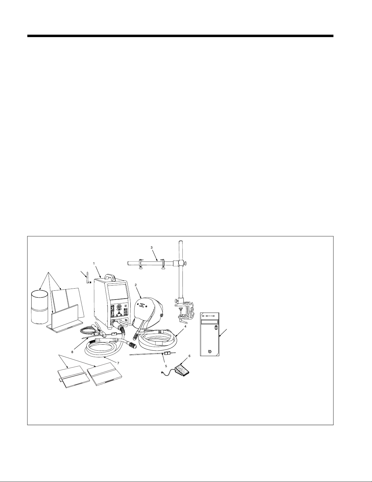
4-3. AugmentedArc Complete Package
Input power and Ethernet cables are
F
not shown.
1 Simulator
2 Helmet
3 Workpiece Stand
4 TIG (GTAW) Torch And Cable
5 TIG Filler Rod
6 TIG RJ45 Foot Pedal And Adapter Cable
(Optional)
7 MIG (GMAW) / Flux Cored (FCAW) Gun
And Cable
8 Stick (SMAW) Electrode Holder And
Cable
9 AR Configurable Workpieces
Five workpieces can be configured for lap, T,
butt, pipe, pipe-to-pipe, and pipe-to-plate
joints.
10 NCCER Coupons
11 WiFi Antenna (Two Total)
12 Controller (Optional, For Classroom Con-
figuration Only)
4-4. Serial Number And Rating Label Location
The serial number and rating information for this product is located on the back of the unit. Use rating label to determine input power requirements, and to register for free software upgrades. For future reference, write serial number in space provided on back cover of this manual.
OM-278680 Page 5
Page 10

4-5. Unit Specifications
Dimensions (L x W x H) Simulator: 17.25 x 9.38 x 21 in. (438 x 238 x 533 mm)
Weight Simulator: 20.7 lb (9.4 kg) AR Welding Helmet: 1.97 lb (0.89 kg)
Input Power 115 to 230 VAC, 0.9A (230 VAC) to 1.8A (115 VAC), 50/60 Hz
External Video Port Resolution External HDMI Port Resolution: 1024 x 768 Pixels Display Port Resolution: 1024 x 768 Pixels
Simulation Modes/Processes Stick (SMAW), MIG (GMAW/FCAW), TIG (GTAW)
Software Version Displayed On System Settings Screen.
Computer OS: Linux
Main Monitor 9.7 in. integrated LCD monitor, 1024 x 768 resolution
PC Requirements For Installation Of
Teacher Software (See Section 9)
Supported Welding Processes Stick (SMAW), MIG (GMAW), Flux Cored (FCAW), TIG (GTAW)
Parameters Tracked By Cameras
Supported Joints Bead On Plate, T-Joint, Butt Joint, Lap Joint, Pipe-Plate, Pipe-Pipe, V-Groove With Backing, V-
Welding Positions 1F, 2F, 3F, 4F, 1G, 2G, 3G, 4G, 5G, 6G
Workpiece Positions Horizontal, Vertical, Flat, Overhead
Voltage Selection MIG (GMAW and FCAW) 10 - 38 Volts
Amperage (Intensity) Selection Stick (SMAW), MIG (GMAW and FCAW), TIG (GTAW): 50 - 425 Amps
Polarity Selection DCEP, DCEN, AC
Shielding Gas Selection CO2, Argon, And Mixtures
Wire Speed Selection MIG (GMAW and FCAW): 50 - 1000 ipm (1.27 - 25.4 m/min)
Base Material Selection Carbon Steel, Stainless Steel, Aluminum
Workpiece Thickness Selection 1/8, 1/4, 3/8 in. (3.2, 6.4, 9.5 mm)
Stick Electrode Selection E7018, E6010, E6013
Stick Electrode Diameter Selection 1/8, 3/32, 5/32 in. (2.50, 3.25, 4.00 mm)
Wire Diameter Selection Solid Wire: 0.030, 0.035, 0.045 in. (0.8, 1.0, 1.2 mm)
Filler Rod Selection 5/64, 3/32 in. (2.0 And 2.4 mm)
Real Time Guide Parameters On-Screen Help Guides Provide Corrective Feedback To User During Simulation
Teacher Software Standalone Application
Helmet Miller Black Infinity Helmet With Premium Headgear. Includes Integrated 4.8 in. LCD display (1024 x
MIG Guns/TIG Torches Miller Brand
Stick Electrode And TIG Filler Rod
Markers
Measurements Global Setting Displays Measurements In Standard (Imperial) Or Metric
Languages English, French, Spanish
Simulator and Helmet (including cables): 23.8 lb (10.8 kg)
Resolution during start-up is 800 x 600 Pixels.
F
Register for free software upgrades at MillerWelds.com/register.
F
Processor: i7
RAM: 4GB DDR3L
Graphics Card: NVIDIA
60GB Solid State Hard Drive
Operating System: Windows 7 (64 bits), Windows 8 (64 bits), Windows 10 (64 bits)
Processor: 2.2 GHz 3 MB
RAM: 4 GB
Display (min): 1366 x 768
Graphic Board: 2GB VRAM Direct X9 compatible graphics card:
NVidia GeForce: 750 or better, or 900 Mobile Series or better
Radeon: HD 6000 series or better, or HD 7000 Mobile series or better
Hard Drive: 1 GB
MIG: Work Angle, Travel Angle, Travel Speed, Contact Tip To Work Distance (CTWD), Aim
Stick: Work Angle, Travel Angle, Travel Speed, Arc Length, Aim
TIG: Rod Work Angle, Rod Filler Angle, Travel Angle, Travel Speed, Arc Length, Aim, Work Angle
Groove Without Backing
600), and integrated speakers.
AR Marker Attachment
®
Quadro®T1000
4-6. Software Licensing Agreement
The End User License Agreement and any third-party notices and terms and conditions pertaining to third-party software can be found at
https://www.millerwelds.com/eula and are incorporated by reference herein.
OM-278680 Page 6
Page 11
4-7. Information About Default Weld Parameters And Settings
NOTICE – Each welding application is unique. Although certain Miller Electric products are designed to determine and default to certain typical
welding parameters and settings based upon specific and relatively limited application variables input by the end user, such default settings are
for reference purposes only; and final weld results can be affected by other variables and application-specific circumstances. The appropriateness of all parameters and settings should be evaluated and modified by the end user as necessary based upon application-specific requirements. The end user is solely responsible for selection and coordination of appropriate equipment, adoption or adjustment of default weld
parameters and settings, and ultimate quality and durability of all resultant welds. Miller Electric expressly disclaims any and all implied warranties including any implied warranty of fitness for a particular purpose.
4-8. Environmental Specifications
A. Temperature Specifications
Operating Temperature Range Storage/Transportation Temperature Range
41 to 113°F (5 to 45°C) -4 to 140°F (-20 to 60°C)
OM-278680 Page 7
Page 12
SECTION 5 – INSTALLATION
5-1. Selecting A Location
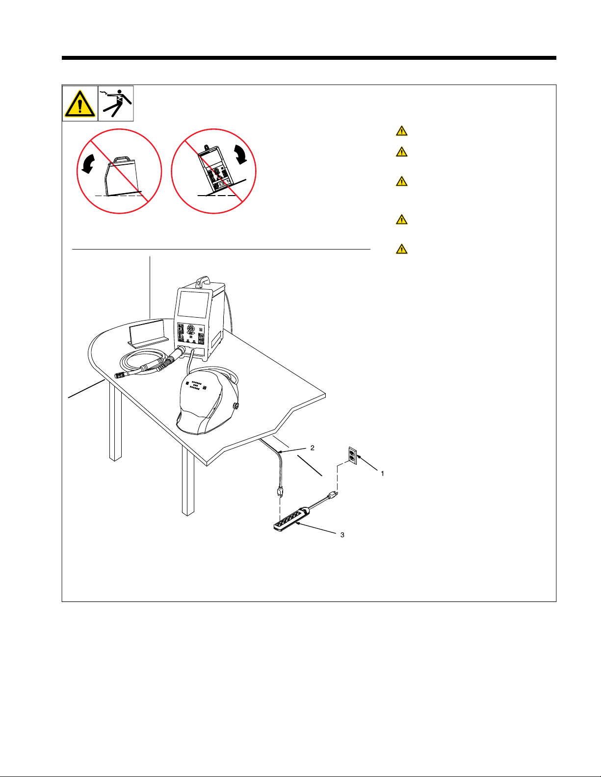
Do not move or operate unit where
it could tip.
Only qualified persons should install, operate, maintain, and repair
this unit.
Installation must meet all National,
State, and Local Codes - have only
qualified persons make this
installation.
Do not move unit by pulling on
simulator, router, helmet, or cables
or equipment may tip.
Do not use this equipment to support personnel, large tools, or other material.
NOTICE – Use training system only indoors
and away from sources of high frequency
(TIG welders) and other types of electrical interference. It may be necessary to enclose
nearby electrical wiring in conduit if unit is affected by interference.
NOTICE – Do not use training system in
damp or wet locations. Keep training system
components dry.
NOTICE – Do not position training system
where the cameras are in direct sunlight.
High intensity sunlight can interfere with gun
tracking.
NOTICE – Do not install or use the Augmented Arc in the same area as live welding
equipment.
1 120 or 240 Volt, 50/60 Hz, 15 Amp AC
Grounded Receptacle
2 Input Power Cord(s)
3 Surge-Protected Power Strip (Customer
Supplied)
OM-278680 Page 8
Position unit near the 120 or 240 volt AC receptacle but away from obstructions that
may restrict movement of cables and gun/
electrode holders.
A 120 or 240 volt AC, 15 amp individual
F
branch circuit protected by time delay
fuses or circuit breaker is required. Use
of a surge-protected power strip is
recommended.
Page 13
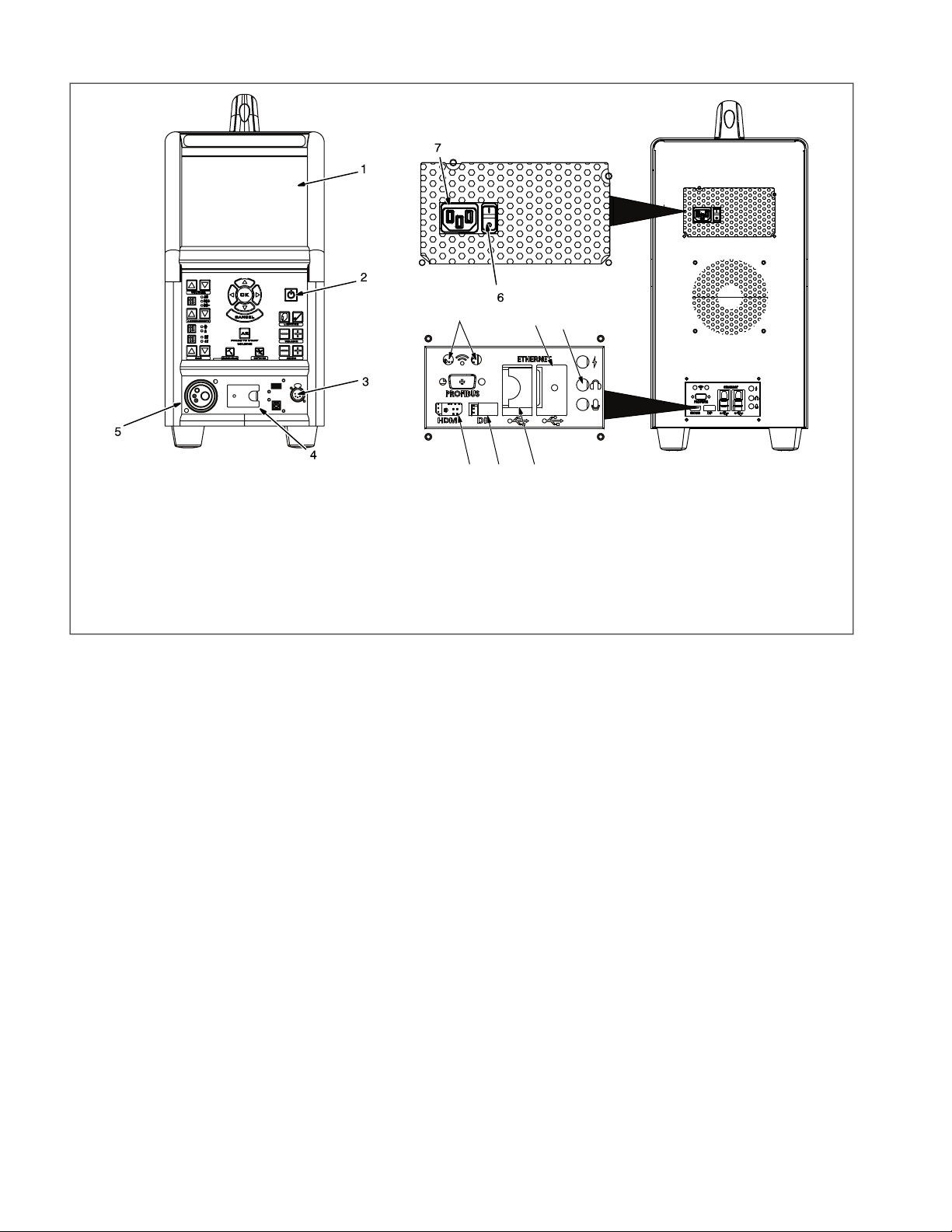
5-2. Simulator Components
8
9
10
11
1213
1 Display Screen
2 Control Panel (See Section 6-1)
3 Electrode Holder And TIG RJ45 Foot
Pedal Receptacle
4 AR Helmet Cable (Not Shown)
5 MIG / Flux Cored (FCAW) And TIG Ca-
ble Receptacle
6 Input Power Switch
7 120 Volt AC Input Receptacle
8 HDMI Receptacle
9 Audio Output Receptacle
10 Wireless (WiFi) Antenna Receptacles
11 USB Receptacle
12 Ethernet Receptacle
13 Display Port Receptacle
OM-278680 Page 9
Page 14
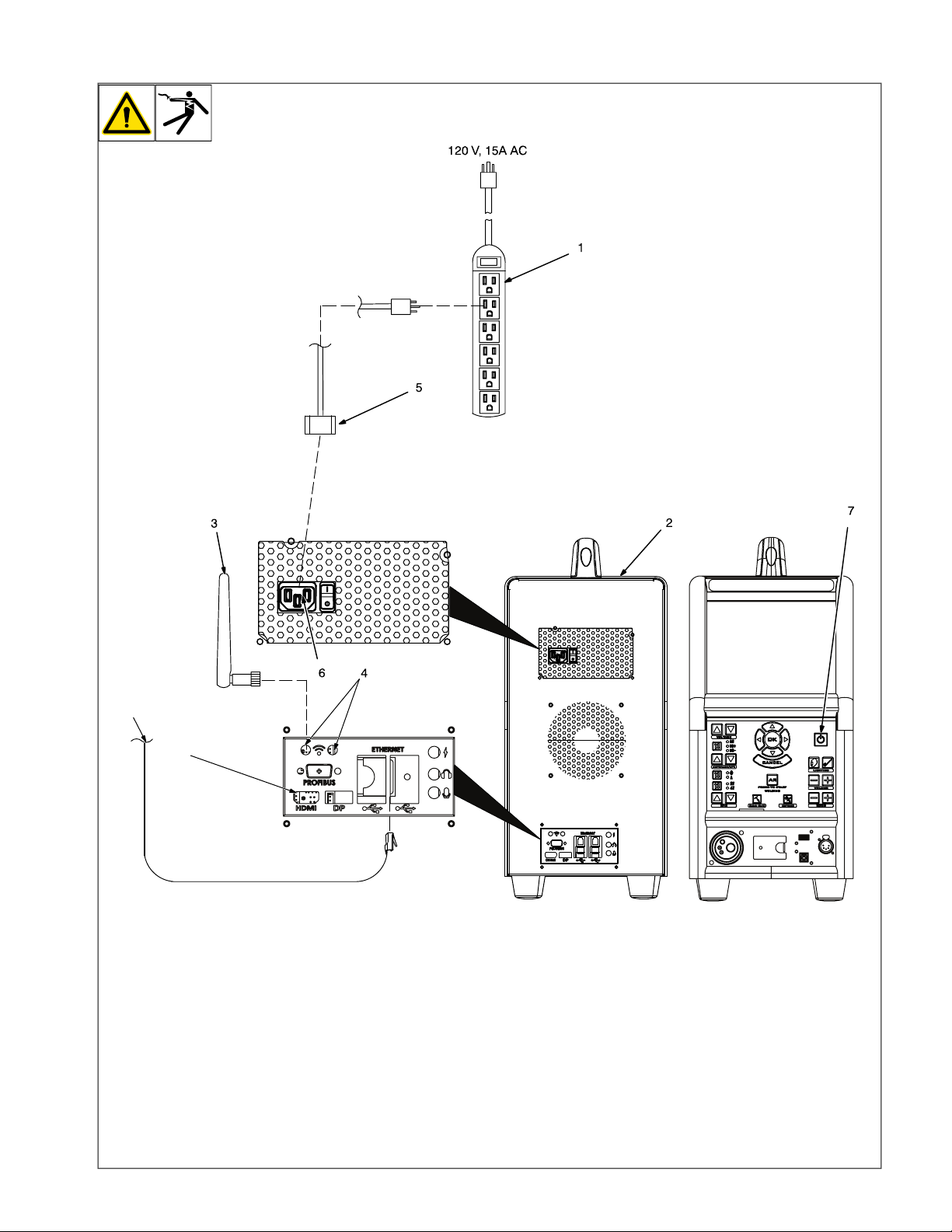
5-3. Installing The Training System—Standalone Configuration
8
9
Use standalone configuration when
F
system is not set up with optional
controller.
1 120 Volt 15 Amp AC Receptacle Or
Power Strip
Use of a surge-protected power strip is
F
recommended.
2 Simulator
3 WiFi Antenna (One Shown)
4 WiFi Antenna Receptacles
Connect both antennas to receptacles on
simulator.
OM-278680 Page 10
5 Simulator Power Cable
Connect one end of simulator power cable
to simulator. Connect other end of power
cord to 120 volt AC receptacle.
6 Input Power Switch
7 Power On/Off Button
Starting Sequence
l Place controller Input Power switch in
On position.
l Press and release the Power On/Off
button and wait 90 seconds for controller to start up.
Information on using the Teacher Soft-
F
ware program is provided in Section
9).
8 IP Network
9 HDMI Receptacle
See Section 5-5 to connect an external
F
monitor to the HDMI receptacle.
Page 15
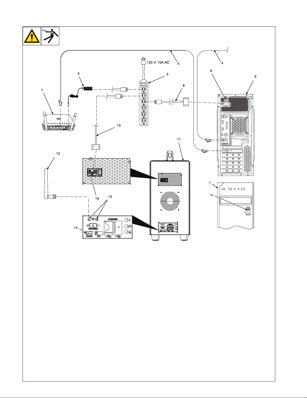
5-4. Installing The Training System With Optional Controller - Classroom Configuration
1 Classroom Router
It is important that only the classroom
F
router is used and that all standalone
routers are not turned on. The classroom router is included with the
controller.
2 Router Power Cable
3 120 Volt 15 Amp AC Receptacle
Use of a surge-protected power strip is
F
recommended.
For best results, locate router within 39
F
in. (1 m) of simulator.
Connect one end of router power cable to
receptacle on back of router. Connect other
end of cable to 120 volt AC receptacle.
Wait about 90 seconds until the WiFi signal
icon on the router is illuminated.
4 Network (Ethernet) Cable
5 Local AugmentedArc Network (Ethernet)
Cable
6 Controller Back
7 Controller Front
The controller must have the same ver-
F
sion of the software as the simulator
(see Section 8-3).
Connect one end of network cable to receptacle LAN1 on back of router. Connect other
end of cable to Network receptacle on controller. Connect IP network cable to internet
receptacle on back of controller.
8 Controller Power Cable
Connect one end of controller power cable
to 120 AC receptacle on back of controller.
Connect other end of cable to 120 volt AC
power supply.
9 Controller Input Power Switch
10 Controller On/Off Button
11 Simulator
12 WiFi Antenna (One Shown)
13 WiFi Receptacles
Connect both WiFi antennas to receptacles
on simulator.
14 HDMI Receptacle
See Section 5-5 to connect an external
F
monitor to the HDMI receptacle.
15 Simulator Power Cable
Connect one end of power cable to simulator. Connect other end of power cord to 120
volt AC receptacle.
16 Simulator Input Power Switch
Starting Sequence
l Place controller Input Power switch in
On position.
l Press and release the On/Off button
and wait 90 seconds for controller to
start up.
l Place simulator Input Power switch in
On position.
l Press the simulator On/Off button (on
front panel) and allow 90 seconds for
simulator to start up completely.
l Change system mode to Classroom
(see Section 8-2).
To use the teacher software in either the
classroom or standalone configuration, connect a laptop or PC to the network provided
by the router.
Information on using the Teacher Soft-
F
ware program is provided in Section 9.
OM-278680 Page 11
Page 16
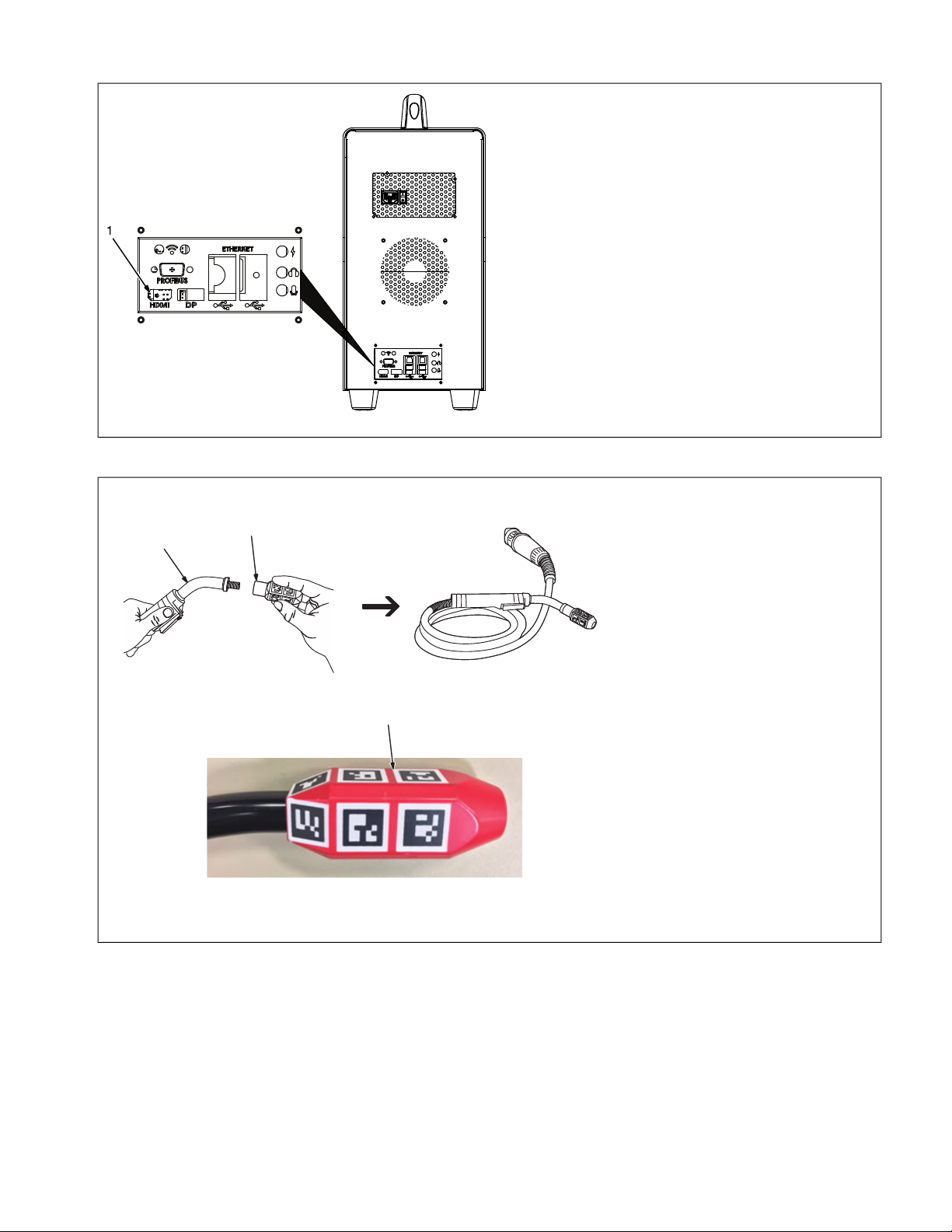
5-5. Connecting Simulator To An External Monitor
3-5. Connecting Simulator To An External Monitor
1 HDMI Receptacle
Use the HDMI receptacle to connect
the simulator to an external monitor.
(HDMI cable is not supplied.)
The external monitor must be con-
nected to the simulator at start-up for
the HDMI output to be enabled. If the
simulator is already turned on, con-
nect the external monitor via HDMI
and then restart the simulator
Due to the various resolution set-
tings of commercial monitors,
some external monitors will show
the initial start-up screens but not
any subsequent screens. To re-
solve this problem, after the simu-
lator starts up, disconnect the
HDMI cable from the simulator
and then reconnect it.
1
3-6. Assembling AR MIG Gun
1 AR MIG Welding Gun
2 MIG Gun AR Nozzle
Locate gun AR nozzle supplied with
system.
Screw AR nozzle on gun (clockwise).
1
2
2
5-6. Assembling AR MIG Gun
1 HDMI Receptacle
Use the HDMI receptacle to connect the simulator to an external monitor. (HDMI cable is
not supplied.)
The external monitor must be connected to
the simulator at start-up for the HDMI output
to be enabled. If the simulator is already
turned on, connect the external monitor via
HDMI and then restart the simulator
Due to the various resolution settings
F
of commercial monitors, some external
monitors will show the initial start-up
screens but not any subsequent
screens. To resolve this problem, after
the simulator starts up, disconnect the
HDMI cable from the simulator and
then reconnect it.
1 AR MIG Welding Gun
2 MIG Gun AR Nozzle
Locate gun AR nozzle supplied with system.
Screw AR nozzle on gun (clockwise).
OM-278680 Page 12
Page 17
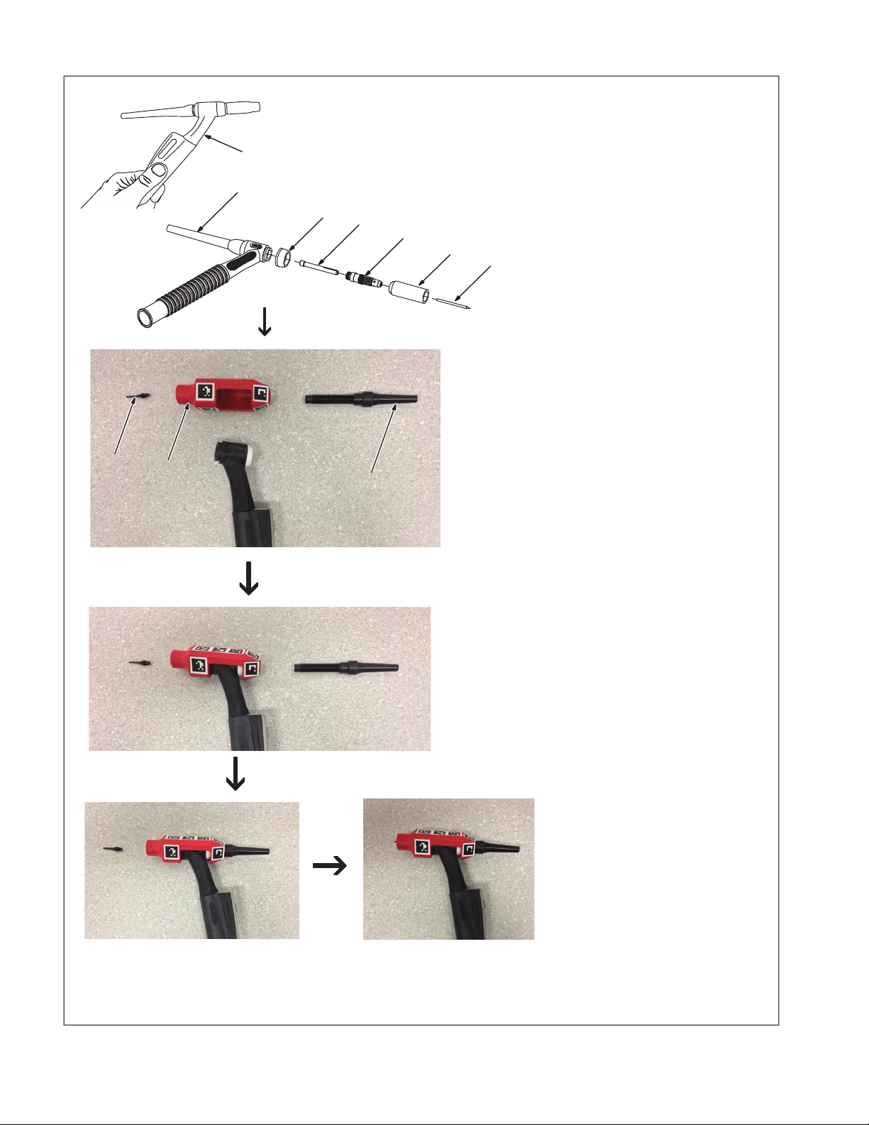
5-7. Assembling AR TIG Torch
9
8
10
2
3
4
5
6
7
1
1 AR TIG Torch
2 Backcap
3 Gas Lens
4 Collet Body
5 Tungsten Electrode
6 Collet
7 Insulator
Remove backcap (counterclockwise).
The original backcap is not used in the
F
AR TIG torch assembly and can be
discarded.
Remove gas lens and collet body.
Remove tungsten electrode and collet.
Remove insulator.
8 TIG Torch AR Nozzle
9 TIG Torch AR Tip
10 TIG Torch AR Backcap
Insert electrode tip into AR nozzle.
Locate the opening in the center of the AR
nozzle. Orient this opening downward and
place over top of torch with the small hole
facing rear of torch.
OM-278680 Page 13
Page 18
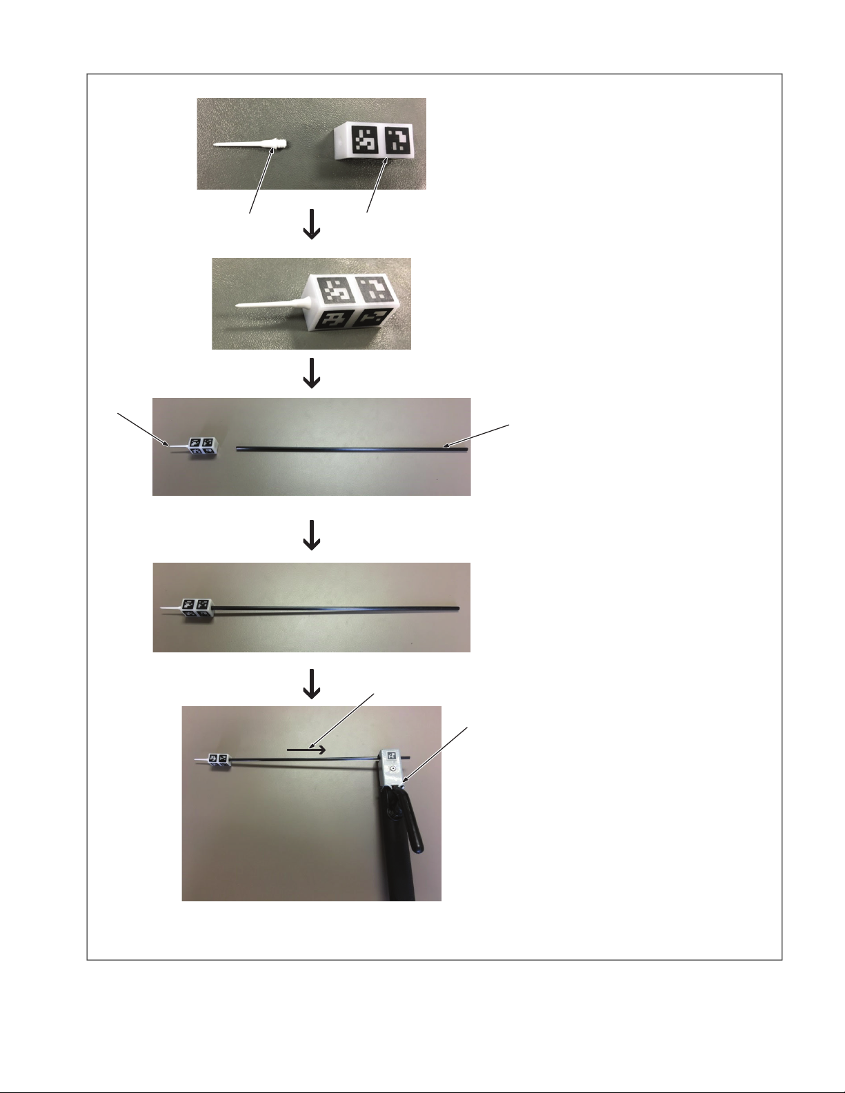
5-8. Assembling AR Stick Electrode/TIG Filler Rod
3
4
5
1
2
6
1 Marker Tip
2 Marker Block
Screw the marker tip into the marker block.
3 Marker Assembly
4 Electrode
Press fit the marker assembly over the tip of
the electrode.
This assembly will also be used as the
F
TIG filler rod.
5 Electrode Holder
Place the electrode in holder as shown.
6 Motor Direction Of Electrode
OM-278680 Page 14
Page 19
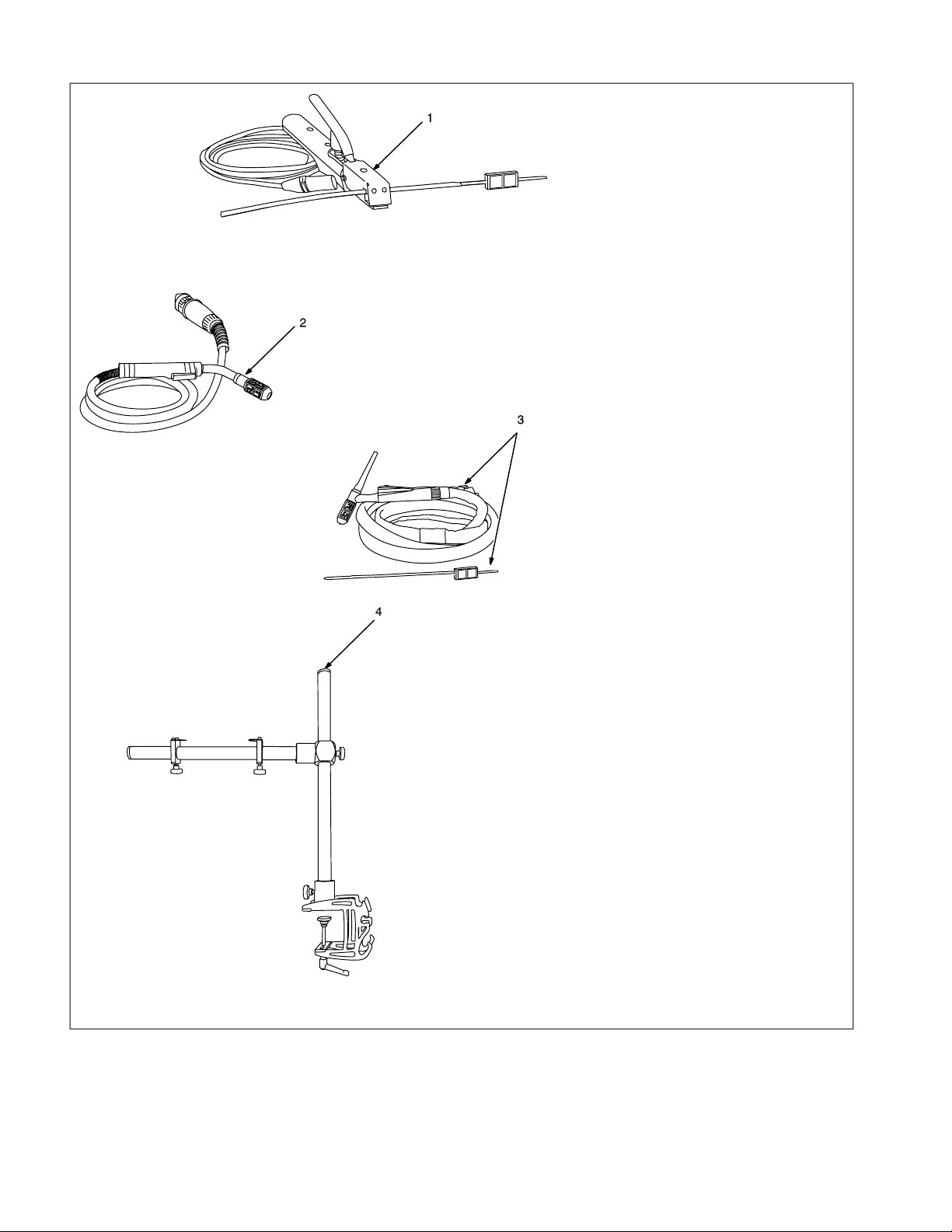
5-9. AR Stick Electrode, MIG Gun, And TIG Torch
1 AR Stick Electrode And Holder
Markers on the stick electrode allow it to
work with the AR system. The electrode is
similar in shape, weight, and size to a real
electrode. It is placed within the holder,
which is connected to the simulator. The
holder retracts the electrode during welding
exercises to simulate the electrode consumption in real welding.
Install Stick electrode in holder exactly
F
as shown.
2 AR MIG/FCAW Welding Gun
Markers on the AR MIG/FCAW welding gun
allow it to work with the AR system. The gun
is connected to a real welding connector in
the simulator. MIG/FCAW welding is a semiautomatic process that uses a continuous
wire feed as an electrode and an inert (MIG)
gas mixture to protect the weld from contamination. The wire can be solid (GMAW) or
cored (FCAW). The student begins by selecting the shielding gas, wire type, and diameter. After the exercise has begun, the
student adjusts the wire feed speed on the
simulator.
3 AR TIG Torch And Filler Rod
Markers on the TIG (GTAW) torch and AR
filler rod allow it to work with the AR system.
The torch is connected to a real welding connector in the simulator. The filler material is
added to the weld joint by a AR filler rod that
is tracked using the AR marker accessory.
The student adds filler by dipping the rod into
the weld joint, just as in real welding. The AR
filler rod is similar in shape, size, and weight
to a real filler rod and helps the student become familiar with using this equipment.
4 Workpiece Stand
Use to hold workpieces in position for flat,
horizontal, vertical, or overhead welding
exercises.
OM-278680 Page 15
Page 20
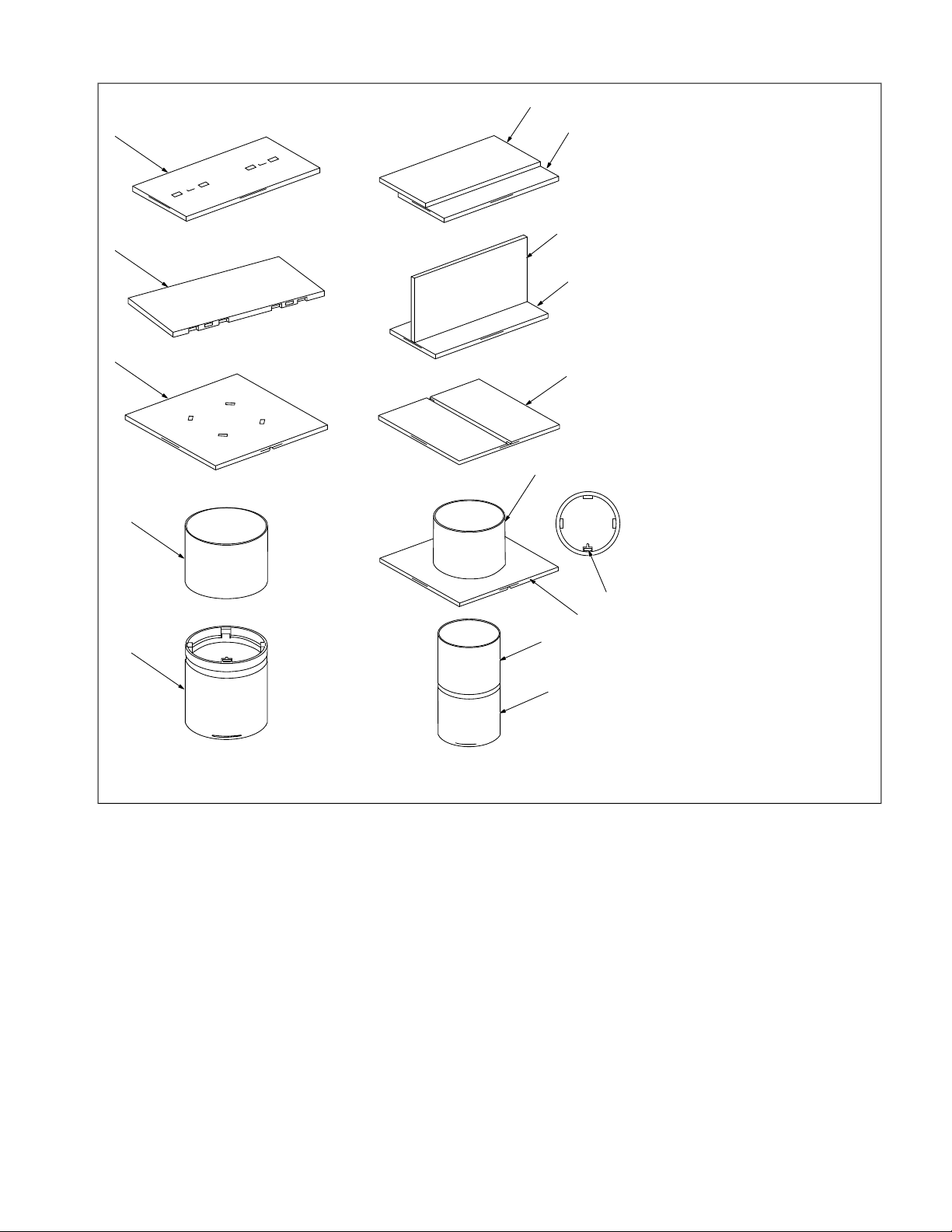
5-10. AR Configurable Workpieces
1
2
3
4
5
5
4
4
3
3
2
1
2
1
6
1 Workpiece A
2 Workpiece B
3 Workpiece C
4 Workpiece D
5 Workpiece E
6 Matching Slot
Connect workpieces A and B as shown for a
lap joint or a T-joint.
Use bottom of workpiece C for butt joint.
Connect workpieces C and D for pipe to
plate joint. Ensure that matching slots are
aligned.
Connect workpieces D and E for pipe to pipe
joint.
OM-278680 Page 16
Page 21
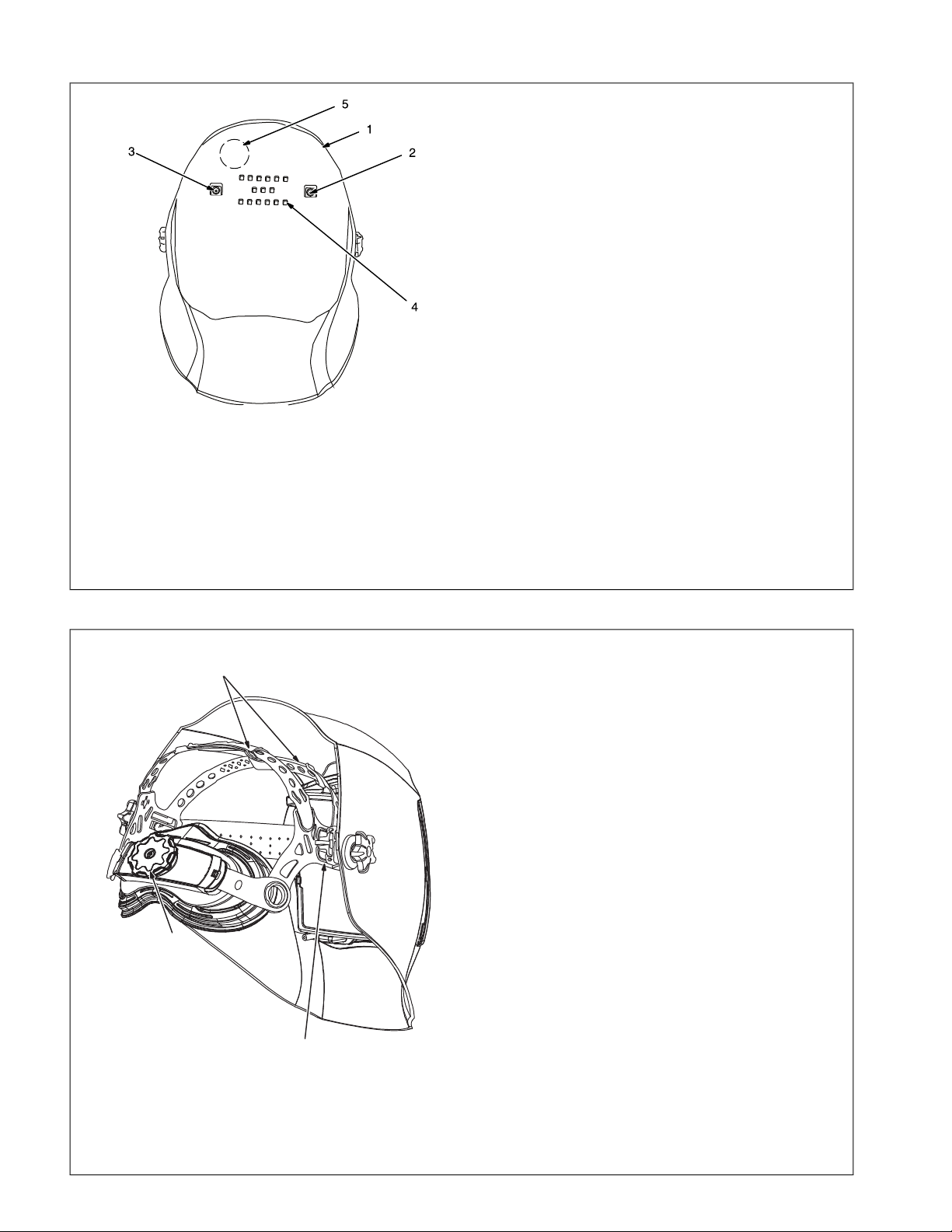
5-11. AR Welding Helmet
1 AR Welding Helmet
2 Left Micro-Camera
3 Right Micro-Camera
The AR welding helmet has two high reso-
lution micro-cameras and a 4.8 in. (122
mm) internal display screen. The cameras
track the workpiece and gun/electrode
markers and convey the weld data (gun
angles, gun speed, contact tip to work dis-
tance [CTWD], aim) to the system micro-
processor. The AugmentedArc acces-
sories (workpieces, guns, torches, elec-
trode, filler rod) and the real environment
are displayed on the helmet screen and
these elements interact to create a re-
al-time augmented reality welding experi-
ence.
4 LED Lights
5 Speaker
The AR welding helmet includes LED
lights (controlled at the simulator) to main-
tain the stable light environment neces-
sary for the artificial vision technology to
work properly.
The AR welding helmet is also equipped
with speakers to recreate the sounds emit-
ted during the welding process to make the
training more authentic.
See Section 8 for information on in-
stalling the optional magnifying lens.
1
161-97
5
2
3
4
Helmet image is intended only for
reference in locating helmet ad-
justments.
There are four headgear adjust-
ments: headgear top, tightness,
angle, and distance.
1 Headgear Top
Adjusts headgear for proper depth on
the head to ensure correct balance and
stability.
2 Headgear Tightness
To adjust, turn the adjusting knob lo-
cated on the back of the headgear left
or right to desired tightness.
3 Angle Adjustment (Not Shown)
Seven slots on the right side of the
headband provide adjustment for the
forward tilt of the helmet. To adjust, lift
and reposition the control arm to the
desired position.
4 Distance Adjustment
Adjusts the distance between the face
and the lens. To adjust, press black
tabs on the top and bottom of the pivot
point and use other hand to slide
headgear forward or backward. Re-
lease tabs. (Both sides must be equal-
1
2
4
5-12. Making Helmet Adjustments
1 AR Welding Helmet
2 Left Micro-Camera
3 Right Micro-Camera
The AR welding helmet has two high resolution micro-cameras and a 4.8 in. (122 mm)
internal display screen. The cameras track
the workpiece and gun/electrode markers
and convey the weld data (gun angles, gun
speed, contact tip to work distance [CTWD],
aim) to the system microprocessor. The AugmentedArc accessories (workpieces, guns,
torches, electrode, filler rod) and the real environment are displayed on the helmet
screen and these elements interact to create
a real-time augmented reality welding
experience.
4 LED Lights
5 Speaker
The AR welding helmet includes LED lights
(controlled at the simulator) to maintain the
stable light environment necessary for the
artificial vision technology to work properly.
The AR welding helmet is also equipped with
speakers to recreate the sounds emitted during the welding process to make the training
more authentic.
See Section 5-13 for information on in-
F
stalling the optional magnifying lens.
Helmet image is intended only for refer-
F
ence in locating helmet adjustments.
There are four headgear adjustments:
F
headgear top, tightness, angle, and
distance.
1 Headgear Top
Adjusts headgear for proper depth on the
head to ensure correct balance and stability.
2 Headgear Tightness
To adjust, turn the adjusting knob located on
the back of the headgear left or right to desired tightness.
3 Angle Adjustment (Not Shown)
Seven slots on the right side of the headband provide adjustment for the forward tilt
of the helmet. To adjust, lift and reposition
the control arm to the desired position.
4 Distance Adjustment
Adjusts the distance between the face and
the lens. To adjust, press black tabs on the
top and bottom of the pivot point and use
other hand to slide headgear forward or
backward. Release tabs. (Both sides must
be equally positioned for proper vision.)
Numbers on the adjustment slides indi-
F
cate set position so both sides can be
adjusted equally.
OM-278680 Page 17
Page 22
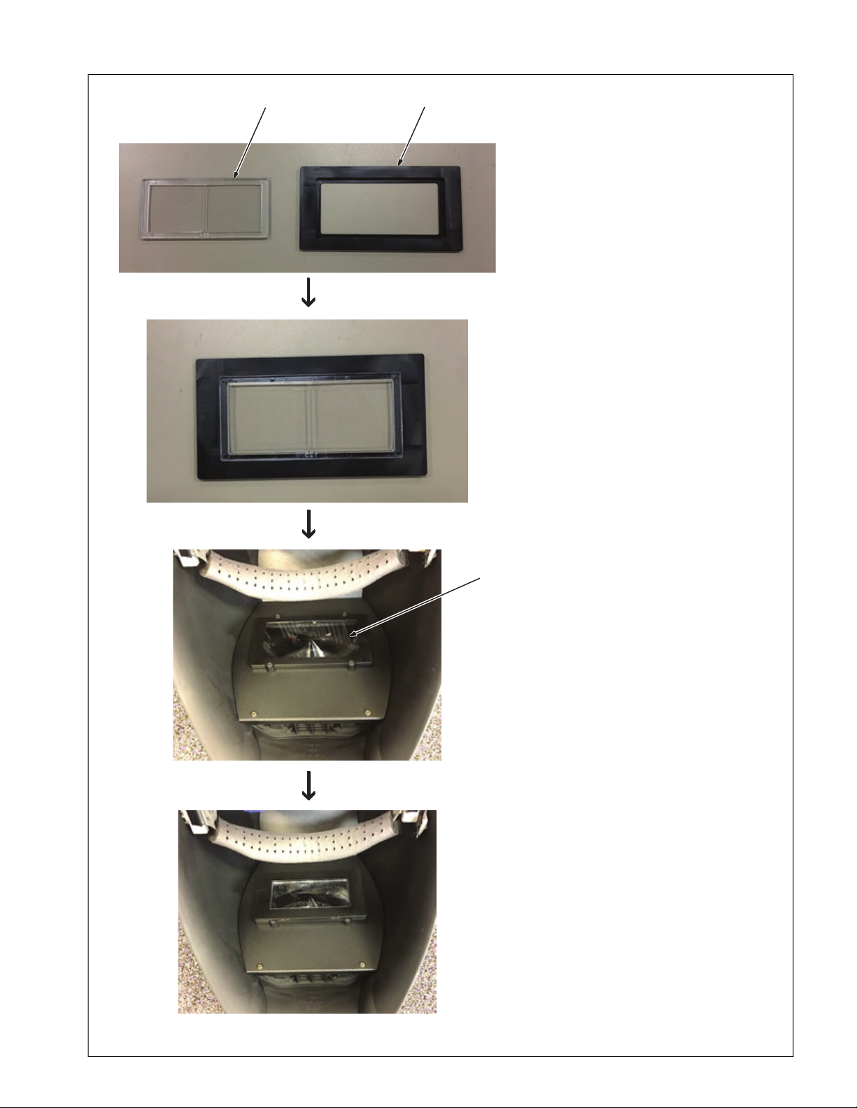
5-13. Installing Optional Magnifying Lens
The magnifying lens can improve the
visibility of the helmet display.
1 Magnifying Lens
See Parts List (Section 10)
2 Magnifying Lens Holder
3 Helmet Lens Assembly
Insert the magnifying lens into the re-
cessed side of the magnifying lens
holder.
With the recessed side of the magni-
fying lens holder facing down, place
the magnifying lens holder on the
helmet lens assembly. Magnets in
the magnifying lens holder will se-
cure it in place.
3
1
2
The magnifying lens can improve the visibility of the helmet display.
1 Magnifying Lens
See Parts List (Section 12)
2 Magnifying Lens Holder
3 Helmet Lens Assembly
Insert the magnifying lens into the recessed
side of the magnifying lens holder.
With the recessed side of the magnifying
lens holder facing down, place the magnifying lens holder on the helmet lens assembly.
Magnets in the magnifying lens holder will
secure it in place.
OM-278680 Page 18
Page 23
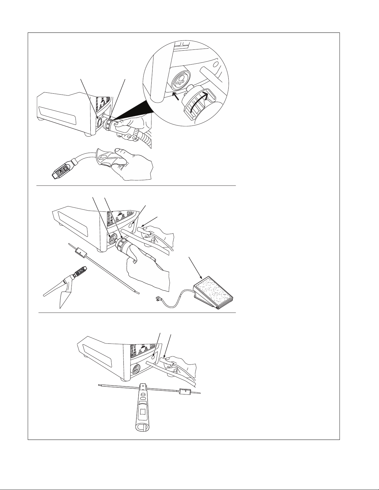
5-14. Connecting Weld Cables
MIG/ Flux Cored (FCAW)
Connections
1 Gun Cable Connector
2 Gun Receptacle
Align pins in connector with holes in re-
ceptacle. Insert connector in recepta-
cle and tighten collar clockwise.
3-12. Connecting Weld Cables
2
TIG Connections
3 Torch Cable Connector
4 Torch Cable Receptacle
Align pins in connector with holes in re-
ceptacle. Insert connector in receptacle
and tighten collar clockwise.
Optional RJ45 Foot Pedal Kit
Connections
TIG foot pedal and adapter cable are
included in optional TIG Foot Pedal
Kit.
5 RJ45 Foot Pedal
6 Adapter Cable
7 RJ45 Foot Pedal Receptacle
Insert foot pedal connector (RJ-45) into
adapter cable receptacle. Insert adapter
cable connector into TIG foot pedal re-
ceptacle on simulator.
Stick Connections
8 Electrode Holder Connector
9 Electrode Holder Receptacle
Align pins in connector with holes in
receptacle. Insert connector in re-
ceptacle.
1
34
8
5
6
7
9
MIG/ Flux Cored (FCAW)Connections
1 Gun Cable Connector
2 Gun Receptacle
Align pins in connector with holes in receptacle. Insert connector in receptacle and
tighten collar clockwise.
TIG Connections
3 Torch Cable Connector
4 Torch Cable Receptacle
Align pins in connector with holes in receptacle. Insert connector in receptacle and
tighten collar clockwise.
Optional RJ45 Foot Pedal Kit
Connections
TIG foot pedal and adapter cable are
F
included in optional TIG Foot Pedal Kit.
5 RJ45 Foot Pedal
6 Adapter Cable
7 RJ45 Foot Pedal Receptacle
Insert foot pedal connector (RJ-45) into
adapter cable receptacle. Insert adapter cable connector into TIG foot pedal receptacle
on simulator.
Stick Connections
8 Electrode Holder Connector
9 Electrode Holder Receptacle
Align pins in connector with holes in receptacle. Insert connector in receptacle.
OM-278680 Page 19
Page 24
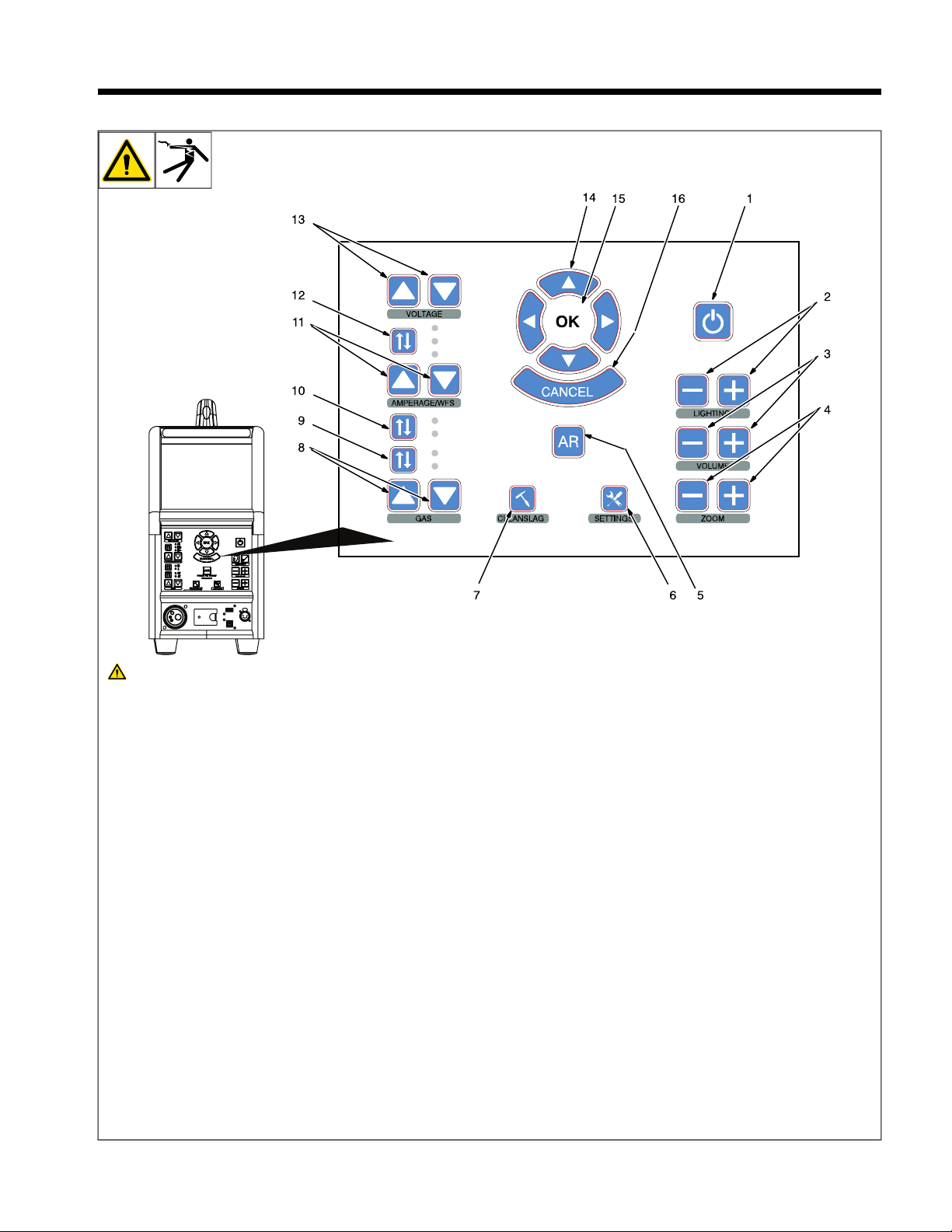
SECTION 6 – SYSTEM CONTROLS AND COMPONENTS
6-1. Simulator Controls
Do not use the welding simulator if
you are light sensitive or affected by
video, flashing lights, or other visual
stimuli. Stop using simulator and
consult your physician if you experience vision problems, nausea, headaches, dizziness, vertigo, or other
conditions.
For best performance, keep helmet,
F
guns, torches, and workpieces free of
dust and debris. Clean components
with a damp cloth. (Do not use chemicals, solvents, or abrasives to clean
markers.)
1 Power On/Off Button
2 Helmet Light Intensity Buttons
Use buttons to increase/decrease intensity
of helmet LED lights.
3 Volume Adjustment Buttons
Use buttons to increase/decrease volume of
helmet speakers.
4 Display (Zoom) Adjustment Buttons
Use buttons to magnify images on display
screen.
5 Augmented Reality (AR) Button
Use button to toggle augmented reality on
and off.
6 System Settings Button
Use the settings menu to change language,
units of measure (standard or metric), camera settings and other parameters.
After starting an exercise, use the System
Settings button to adjust video device settings and lighting (see Section 8-7).
Some settings can only be changed by
F
the system administrator.
7 Clean Slag Button
Use button to remove slag after completing
Stick and FCAW welding exercises. Slag
must be cleaned for test results to be
displayed.
8 Shielding Gas Flow Adjustment Buttons
Use buttons to increase or decrease the flow
of shielding gas for the MIG, Flux Cored,
and TIG weld processes.
9 Gun Trigger Selection Button
Use button to select either two-step or fourstep trigger operation.
10 Amperage/Wire Feed Speed Selection
Button
Use button to select the weld parameter
(amperage or wire feed speed) to be adjusted (see Item 11).
11 Amperage/Wire Feed Speed Adjustment
Buttons
Use buttons to increase or decrease amperage or wire feed speed (see item 10).
12 AC/Polarity Selection Button
Use button to select AC weld output or
DCEP or DCEN weld polarity.
13 Voltage Adjustment Buttons
Use buttons to increase or decrease weld
voltage.
14 System Navigation Buttons
Use buttons to navigate AR system programs and select menu items.
15 OK (System Selection) Button
Use button to activate selected menu items.
16 System Cancel Button
Use button to stop the AR program or activity in use, or return to the previous screen.
OM-278680 Page 20
Page 25

SECTION 7 – OPERATION
Do not use the welding simulator if you are light sensitive or affected by video, flashing lights, or other visual stimuli. Stop using
simulator and consult your physician if you experience vision problems, nausea, headaches, dizziness, vertigo, or other
conditions.
A MIG/FCAW welding simulation is shown in these examples. Setup and adjustments are similar for other welding processes.
F
7-1. Equipment Setup
l Assemble AugmentedArc training system. Install system in proper location and near 120 volt AC power source (see Section 5-1).
l Connect desired gun or torch to simulator (see Sections 5-9and 5-14).
l Connect simulator and router power cords to 120 volt AC receptacles.
l Place simulator Input Power switch (on back of simulator) in On position. Press router Power switch. Press and hold Power On-Off button
on front of simulator until simulator turns on. For Classroom applications, also place controller Input Power switch (on back panel) in On position (see Section 5-4). Press and hold controller Power On/Off button (on front panel) until unit turns on.
OM-278680 Page 21
Page 26
7-2. Getting Started
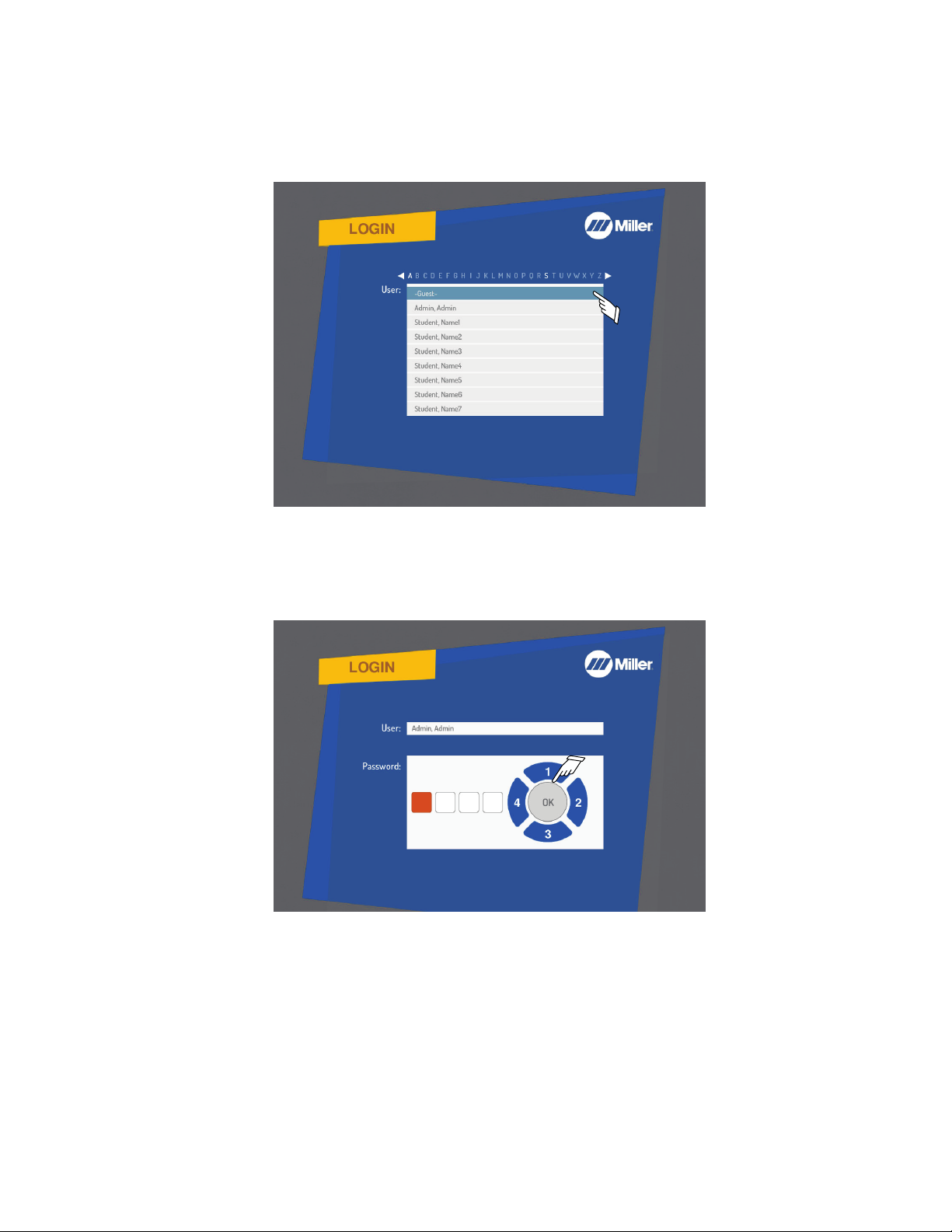
A. Login Screens
Use System Navigation buttons to select guest or user name from Login menu. Press OK.
To create a new user, see Section 9, Using The Teacher Software.
F
Figure 7-1. User Selection Screen
Use Navigation buttons to enter password. Each button represents a number (1 - 4) as shown in Figure 7-2. The default Admin user password is
1111. Press OK.
Passwords are established by the instructor. Guest users do not need a password.
F
Figure 7-2. Password Screen
OM-278680 Page 22
Page 27
B. Course Selection
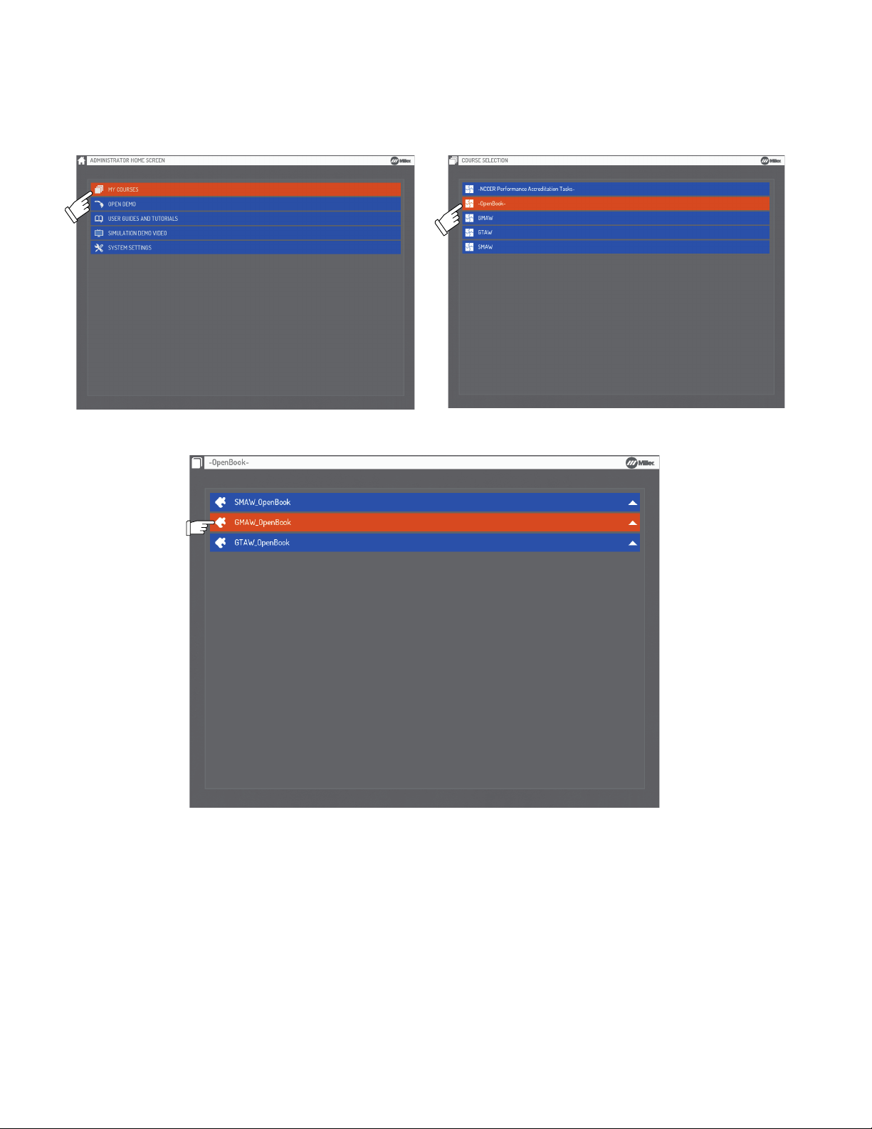
Use System Navigation buttons to select desired course (Figure 7-3). Press OK.
Course selection will vary for each user. The figure reflects default factory-installed courses.
F
Press the Cancel button at any time to stop the program and return to the previous screen.
F
Figure 7-3. Course Selection Screen
Use Navigation buttons to select an Open Book module. See Figure 7-4. Press OK.
Figure 7-4. Open Book Course Selection
OM-278680 Page 23
Page 28
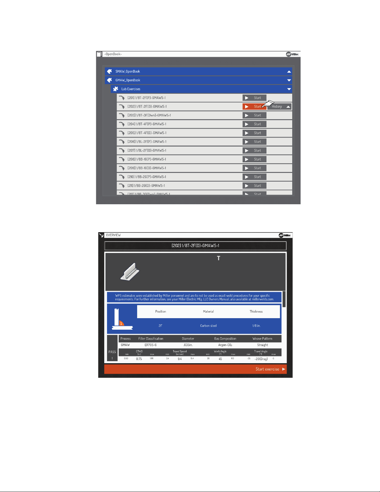
Use Navigation buttons to select (Start) a new exercise session or review previous sessions (under the History tab). See Figure 7-5. Press OK.
The History feature is not available to Guest users.
F
Figure 7-5. Activity Selection Screen
Use Navigation buttons to select or acknowledge the difficulty level (Beginner, Intermediate, Advanced), slag removal requirements, joint type,
position, material type/thickness, weld process, electrode type/diameter, gas composition, and other parameters as applicable (Figure 7-6).
Figure 7-6. Welding Procedure Specification (WPS)
Review welding assignment WPS. Select Start exercise to begin simulation.
OM-278680 Page 24
Page 29
C. NCCER Course Selection
NCCER is a not-for-profit 501(c)(3) education foundation created by the construction industry to develop standardized curriculum and assessments with portable credentials and certifications for skilled craft professionals. NCCER provides a comprehensive workforce development system that includes accreditation, training, assessment, certification and career development solutions for the construction and maintenance
industries. For more information, visit www.nccer.org or contact NCCER customer service at 888.622.3720.
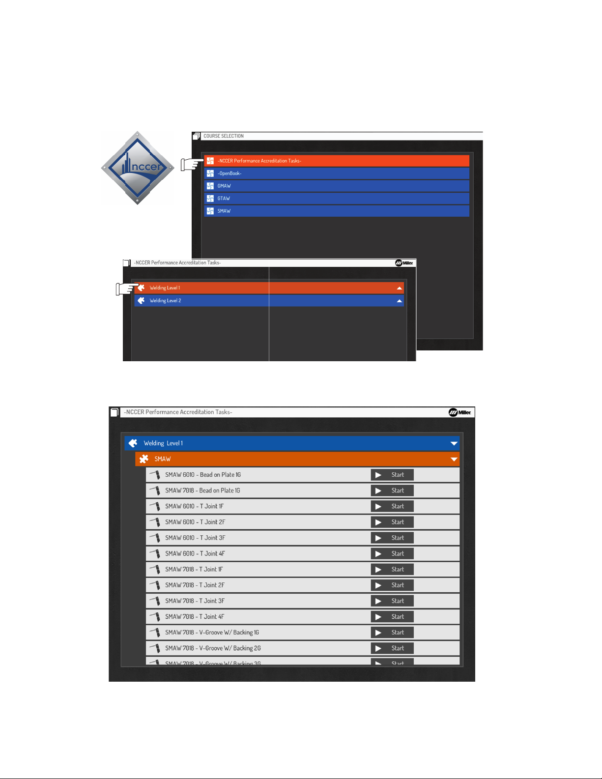
Select NCCER Performance Accreditation Tasks, then select Welding Level 1 or Welding Level 2 for exercises.
Use only NCCER coupons for NCCER courses.
F
Figure 7-7. NCCER Training
NCCER Welding Level 1 focuses on the SMAW Process with Bead on Plate, T Joint, V-Groove with Backing, and V-Groove without Backing
exercises.
Figure 7-8. NCCER Welding Level 1
OM-278680 Page 25
Page 30
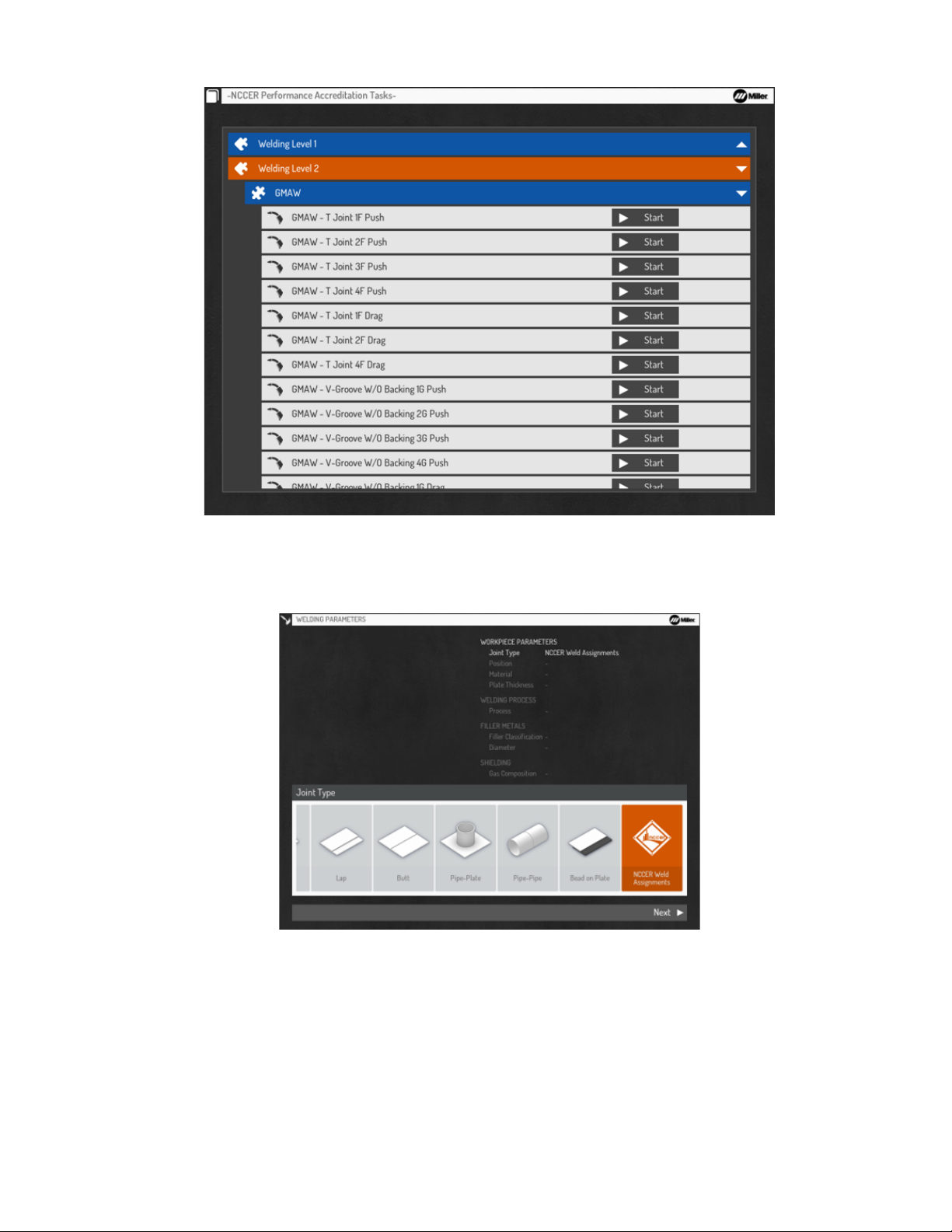
NCCER Welding Level 2 focuses on the GMAW, FCAW-G, and GTAW processes with Bead on Plate, T Joint, V-Groove with Backing, and VGroove without Backing exercises.
Figure 7-9. NCCER Welding Level 2
In Open Exercise, users can complete the NCCER exercises. The exercises are divided by Welding Level 1 and Welding Level 2. All exercises
are set at the intermediate difficulty level.
Figure 7-10. Open Exercise NCCER Assignments
OM-278680 Page 26
Page 31
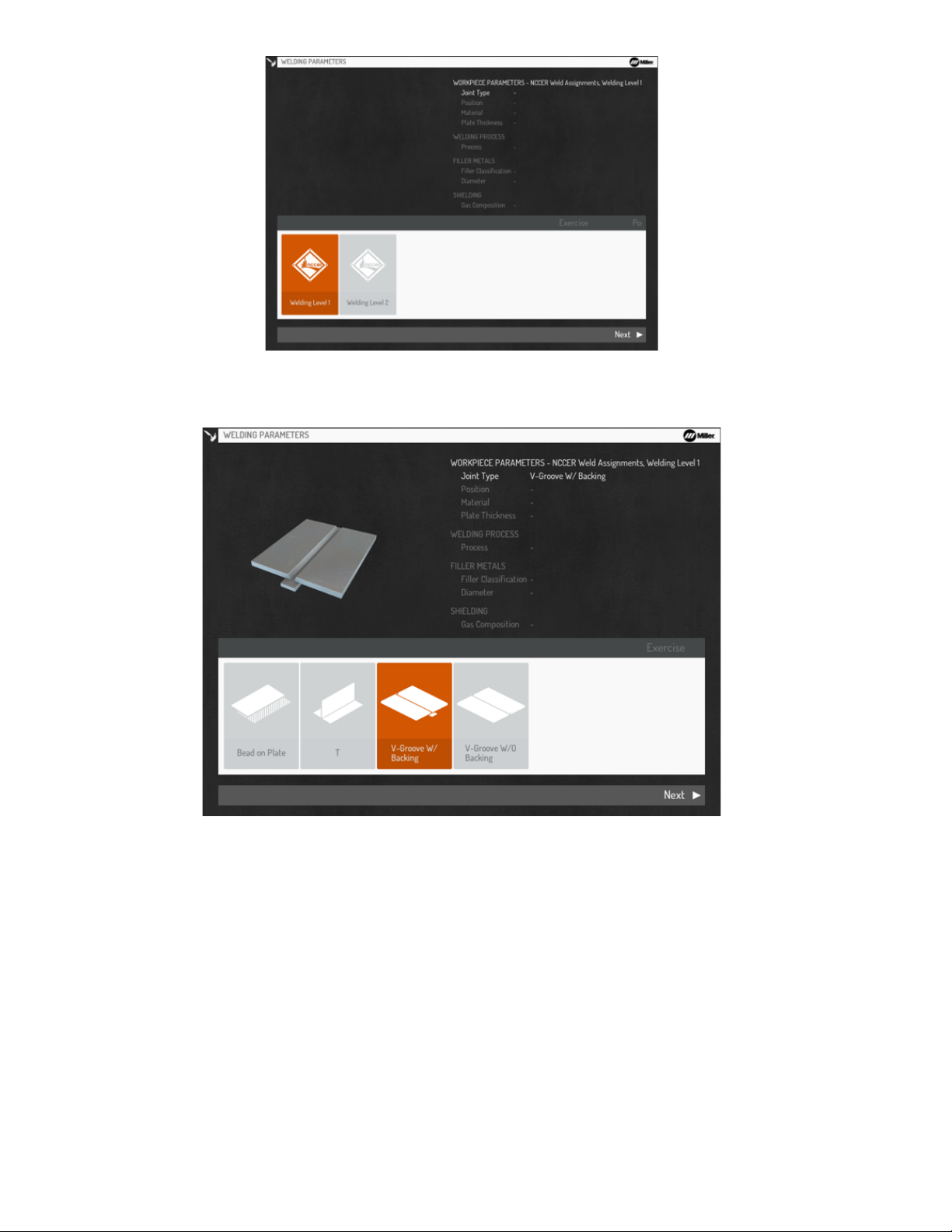
Figure 7-11. NCCER Welding Levels 1 And 2
Select the desired joint type. Then select Next.
Figure 7-12. Selecting Joint Type
OM-278680 Page 27
Page 32
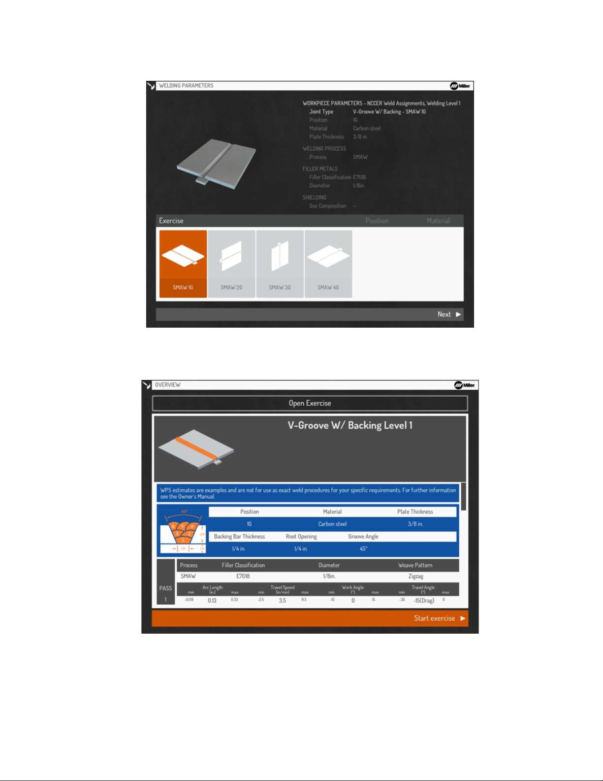
Select the desired position. Then select Next.
Use only NCCER coupons for NCCER courses.
F
Figure 7-13. Selecting Position
Review welding assignment WPS. Select Start exercise to begin simulation.
OM-278680 Page 28
Figure 7-14. Starting Exercise
Page 33
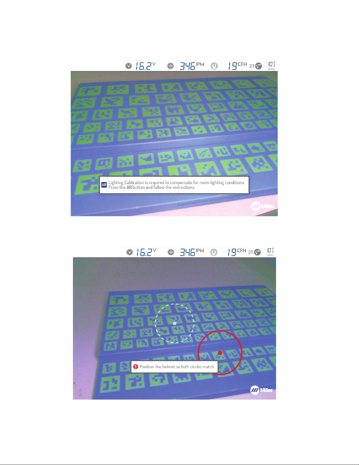
D. Lighting Calibration
Lighting calibration adjusts the video device settings (temperature, intensity) based on the room lighting conditions.
Ensure helmet LEDs are turned on (see Section 6-1). Default setting is full intensity.
Follow the on-screen prompts.
Figure 7-15. Lighting Calibration Screen
When circles appear, aim the helmet so that the dashed white circle is aligned with the red solid circle. Adjust the helmet’s distance from the
workpiece until circles turn green.
Figure 7-16. Lighting Calibration Circles
OM-278680 Page 29
Page 34
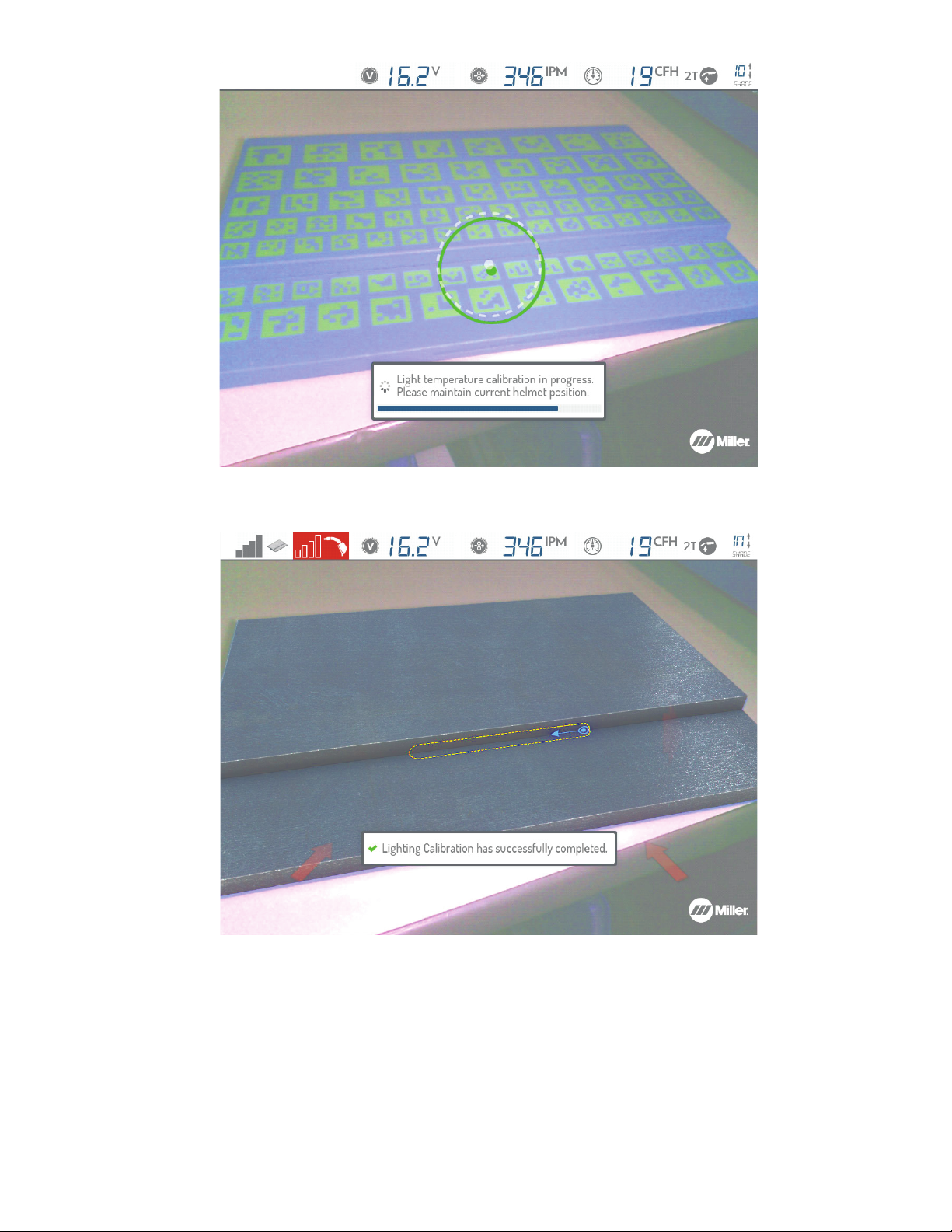
Figure 7-17. Lighting Calibration In Progress
A notification indicates when the process has completed successfully.
Figure 7-18. Lighting Calibration Successful
To repeat the Lighting Calibration process, press the Settings button (see Section 8-7).
OM-278680 Page 30
Page 35
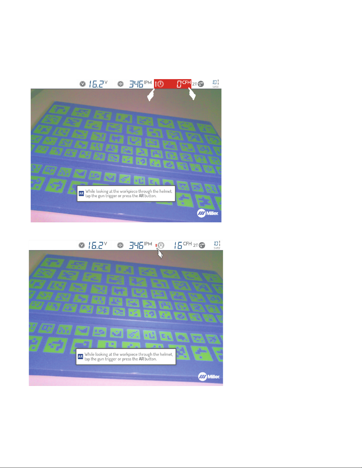
E. Correcting Improper Weld Setting
Look at the workpiece through the AR helmet and tap the gun trigger (MIG/FCAW/TIG) or press the AR button (MIG/FCAW/Stick/TIG). It may be
necessary to adjust video device settings or helmet lighting to compensate for ambient conditions (see Section 6-1). The Display screen shows
current weld voltage, wire feed speed, gas flow, and trigger control selection settings. Settings highlighted in red are outside the programmed parameters for the selected assignment. The arrows displayed on the screen indicate whether to increase or decrease the setting. Equipment settings must be within specifications before welding can begin.
Acceptable ranges and ideal target values of settings are either preset or set by the instructor (see Section 9-4).
F
Improper settings shown in red (gas
F
flow).
Figure 7-19. Example Of Improper Weld Settings
All weld settings are within acceptable
F
ranges, but gas flow not ideal.
Figure 7-20. Example Of Acceptable Weld Settings
OM-278680 Page 31
Page 36
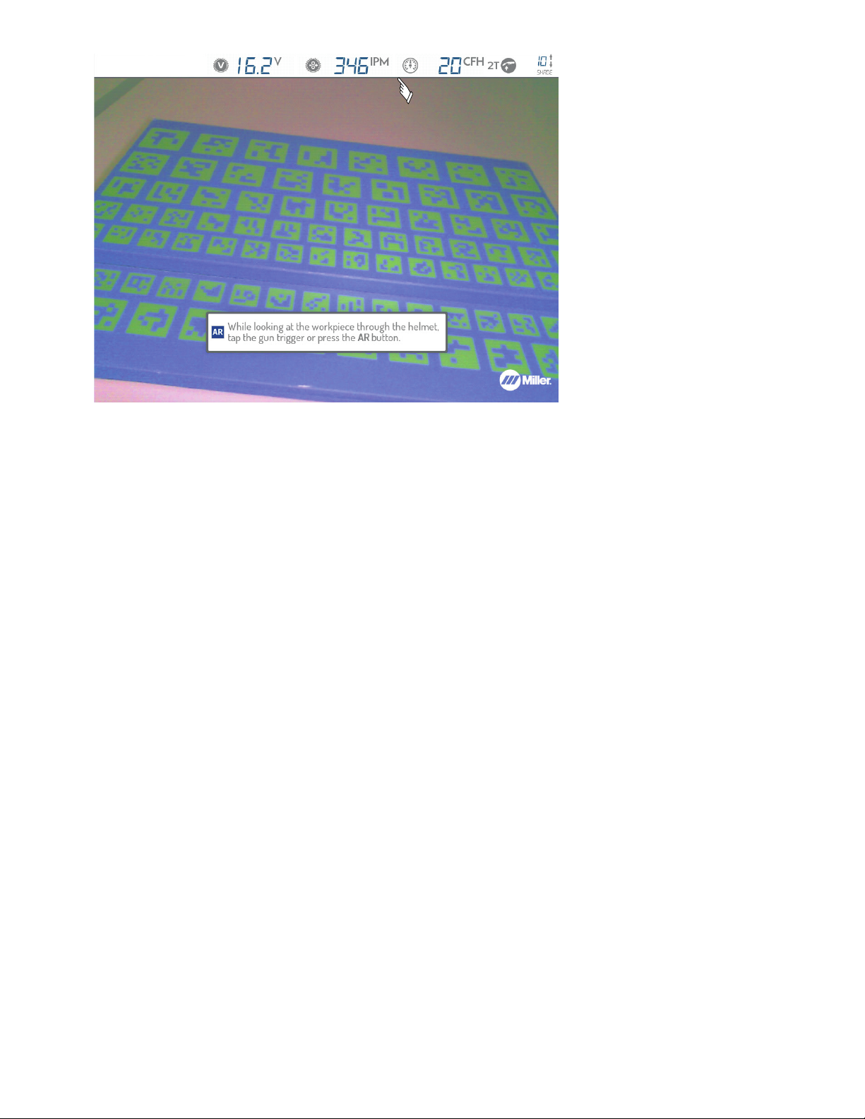
F
Figure 7-21. Example Of Ideal Weld Settings
All weld settings are at ideal values.
OM-278680 Page 32
Page 37
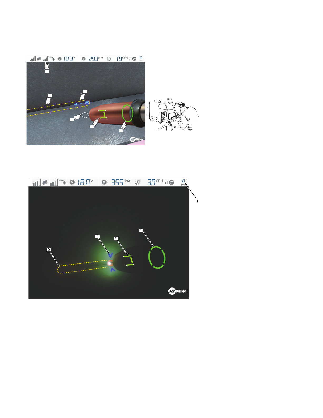
F. Determining Correct Position Of MIG Gun/Electrode And AR Helmet
6
1
5
2
3
4
Place the gun/electrode at the simulated weld joint (visible through the helmet). The screen will display an error message if the system cannot
track the gun/electrode. Adjust gun/electrode position and helmet position to clear the tracking error. Use the simulated guides to adjust the gun/
electrode angle, direction, and contact tip to work distance (CTWD) to acceptable limits. The guide color turns green when the gun/electrode is
properly positioned (Figure 7-22).
For best results, position gun so two
F
faces of AR tip are visible to cameras in
helmet.
1 Gun Tracking Indicator
2 Simulated Weld-Joint Location
3 Exercise Direction of Travel
4 Aim Guide
5 CTWD Guide
6 Work Angle And Travel Angle Guide
Use onscreen guides to ensure correct position of gun/electrode and helmet.
Figure 7-22. Review Gun/Electrode Positioning Guides Before Welding
During the weld simulation, the screen darkens to simulate the shading of an auto-darkening helmet. Use the up/down arrow buttons to adjust
the helmet shade from 8 (lightest) to 13 (darkest), as desired.
1 Currently Selected Helmet Shade
2 Gun Angle Guide
3 Contact Tip-Work Guide
4 Travel Speed Guide
5 Simulated Weld Joint
Top status panel can be configured to
F
be hidden during simulations (see Section 8-2).
Figure 7-23. Gun/Electrode Positioning Guides Displayed While Welding
OM-278680 Page 33
Page 38
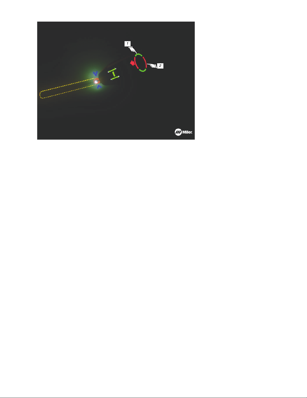
1 Work Angle Guide
2 Travel Angle Guide
Figure 7-24. Gun/Electrode Travel Angle Error
OM-278680 Page 34
Page 39
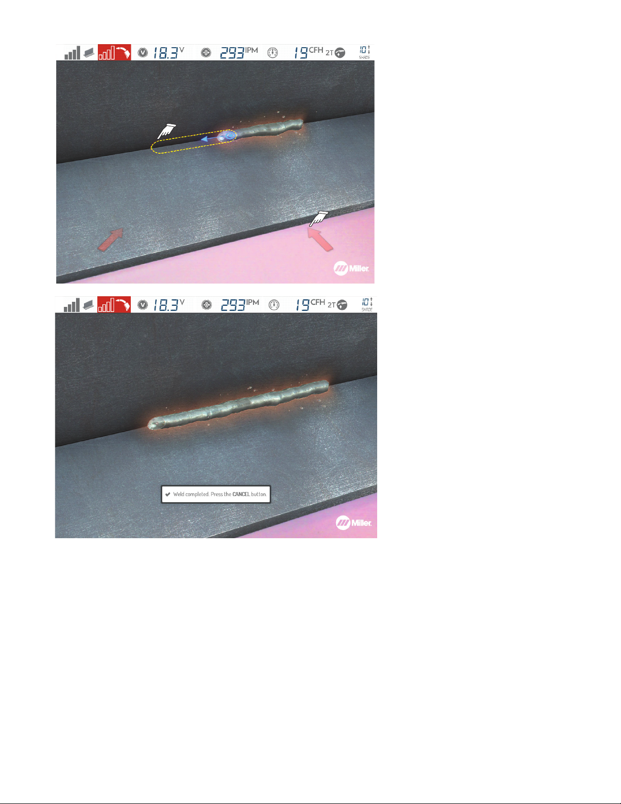
The entire length of the outlined area
F
must be welded before results can be
assessed.
Red arrows indicate AR helmet position
F
should be adjusted for best tracking
results.
Figure 7-25. Arrows Indicating Error In Helmet Position And Completing The Weld
OM-278680 Page 35
Page 40
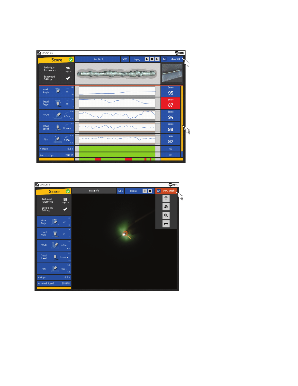
G. Course Analysis
Figure 7-7. Results Of Welding Exercise
After completing the welding exercise, examine scores to determine areas of improvement. Passing scores are shown in blue. Scoring is based
on the techniques and tolerances settings for the assignment. Use the right/left buttons for WPS Summary, Replay and Change View options.
After review, press Cancel button to perform another simulated test, or choose a different assignment.
Press the AR button to switch to 3D
F
view.
Use up/down buttons to move vertical
F
scroll bar and view additional results.
When the blue line is in the middle of the
white area, it indicates performance at ideal
level. When the blue line is at the top or bottom of the white area, it indicates performance outside the specified parameters.
Figure 7-26. Results Of Welding Exercise
Figure 7-27. Replay Of Welding Exercise
Press the AR button to switch back to
F
graphics view.
OM-278680 Page 36
Page 41
SECTION 8 – ADMINISTRATOR SYSTEM SETTINGS
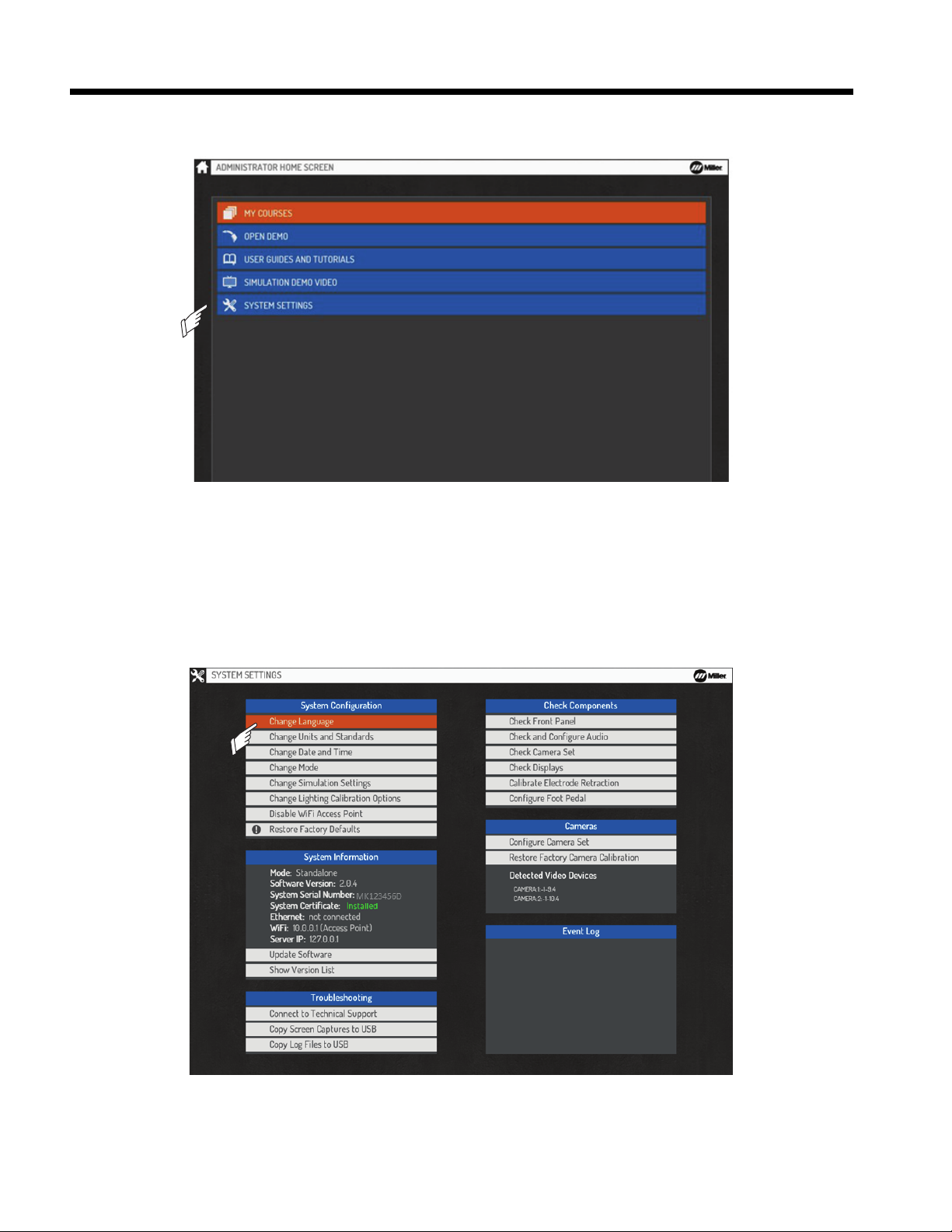
Figure 8-1. Accessing System Settings Screen
8-1. Accessing Administrator Home Screen
Log in as administrator to access the Administrator home screen (Section 7-2). Select System Settings (Figure 8-1) and press OK.
Figure 8-1. Accessing System Settings Screen
8-2. Changing System Configuration
A. Changing System Language Setting
Select Change Language and press OK to select a new language (Figure 8-2). Press Cancel to return to the menu.
English, Spanish, and French are currently available.
F
Figure 8-2. Changing Language Setting
OM-278680 Page 37
Page 42

B. Changing System Units And Standards
Select Change Units and Standards and press OK to change the units of measure (Imperial or Metric) or to change naming conventions. Select Apply and press OK after making changes, or press Cancel to exit the menu without saving.
The Mixed Standard naming convention will display both standards on the welding position selection screen (PB/2F).
F
C. Changing Date And Time
Select Change Date And Time and press OK to change the year, month, day, and time. Select Apply and press OK after making changes, or
press Cancel to exit the menu without saving.
D. Changing Mode
Before changing to Classroom mode, ensure the system is connected as shown in Section 5-4. The controller and the simulator must have
F
the same version of software installed (see Section 8-3).
Select Change Mode and press OK to change the system configuration to Standalone or Classroom. Use Standalone mode for a setup with a
single simulator. Use Classroom mode for a setup with multiple simulators and a controller. Select Apply and press OK after making changes, or
press Cancel to exit the menu without saving.
E. Changing Simulation Settings
Select Change Simulation Settings and press OK to change visibility of the top status panel during simulations, change the virtual nozzle display settings, and change tracking type (Mono or Stereo) for each process.
l Stereo tracking requires both the left camera and right camera to view the marker on the object for the object to be tracked. Stereo tracking
is recommended and results in the best accuracy of the tracked technique parameters.
l Mono tracking uses only the left camera for tracking, which means that if the marker on an object is viewable in the helmet display during
the exercise that the object will be tracked. Mono tracking has lower accuracy but may reduce tracking issues.
F. Changing Lighting Calibration Options
Select Change Lighting Calibration Options and press OK to change the frequency with which the system prompts the user to perform the
lighting calibration process. See Section 7-2.
G. Changing WiFi Access Point Settings
Select Enable WiFi Access Point to broadcast a WiFi network directly from the simulator without the need for a router (only available in standalone mode).
OM-278680 Page 38
Page 43
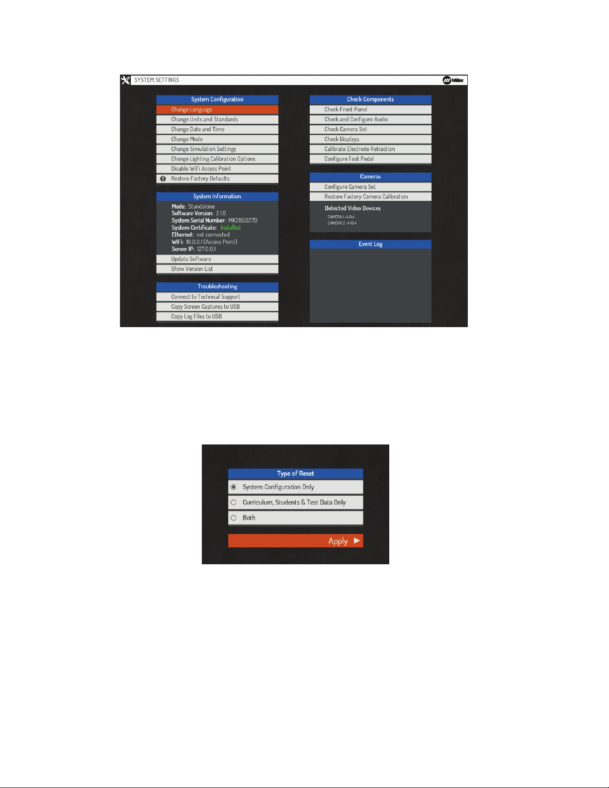
H. Restoring Factory Configuration
Figure 8-3. Restoring Factory Configuration
To reset system to the original factory configuration, select Restore Factory Defaults and then press OK (Figure 8-3). A confirmation message
will be displayed. Make a selection to either proceed or cancel.
Figure 8-3. Restoring Factory Configuration
For a system in Classroom Mode, the restore process will restore the simulator to original factory conditions, but will not affect the system curriculum (courses, students, student history). These changes can only be made by using the Teacher Software (see Section 9). For a system in
Standalone Mode, a number of reset options are provided (see Figure 8-4). Selecting System Configuration Only will restore the system to
original factory conditions, but will not affect the system curriculum. Selecting Curriculum, Students, & Test Data Only will erase all customized
system content and restore the system content to the factory defaults. Selecting Both will restore the system configuration and content to original factory conditions.
You can use the Teacher Software to create a backup file of the complete system curriculum, students, and test data, which can be re-
F
loaded onto the system at a later date (See Section 9-7).
Figure 8-4. Type Of Reset
OM-278680 Page 39
Page 44
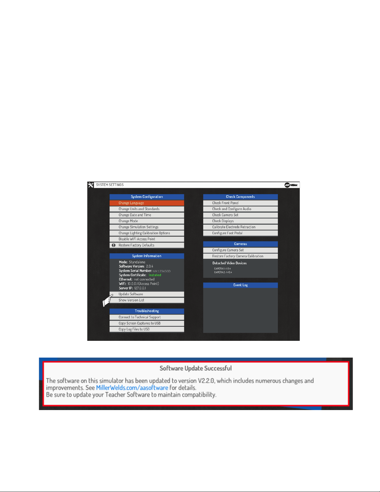
8-3. Software Updates
Figure 8-3. Restoring Factory Configuration
Figure 8-4. Type Of Reset
Software update files and detailed update instructions can be found online at https://www.millerwelds.com/aasoftware.
F
A. Software Updates—Standalone Mode
During start-up, the system automatically installs software updates provided through an Internet connection (if available) or USB memory stick (if
connected).
To manually initiate a software update, select Update Software and press OK (Figure 8-5). Select Internet if the system is connected to the Internet; select USB Stick if the software will be installed from a USB memory stick (connected to the USB receptacle on the back of the simulator)
(Section 5-2). Press OK after making changes, or press Cancel to exit the menu without saving.
After a successful software update, a confirmation message will be displayed on the Login screen indicating the new version of software in-
F
stalled. Be sure to also update the Teacher Software to the latest version to maintain compatibility (see Section 9-1).
B. Software Updates—Classroom Mode
During start-up, the controller automatically installs software updates provided through an Internet connection (if available) or USB memory stick
(if connected). Controller software installation may take up to five minutes. After a software update is installed on the controller, restart each simulator to automatically download the updated software from the controller.
To manually download the updated software from the controller to the simulators, select Update Software and then press OK, and then select
Update from Server. Press OK after making changes, or press Cancel to exit the menu without saving.
After a successful software update, a confirmation message will be displayed on the Login screen indicating the new version of software in-
F
stalled. Be sure to also update the Teacher Software to the latest version to maintain compatibility (see Section 9-1).
Figure 8-5. Updating Software
OM-278680 Page 40
Figure 8-6. Software Update Confirmation Message
Page 45
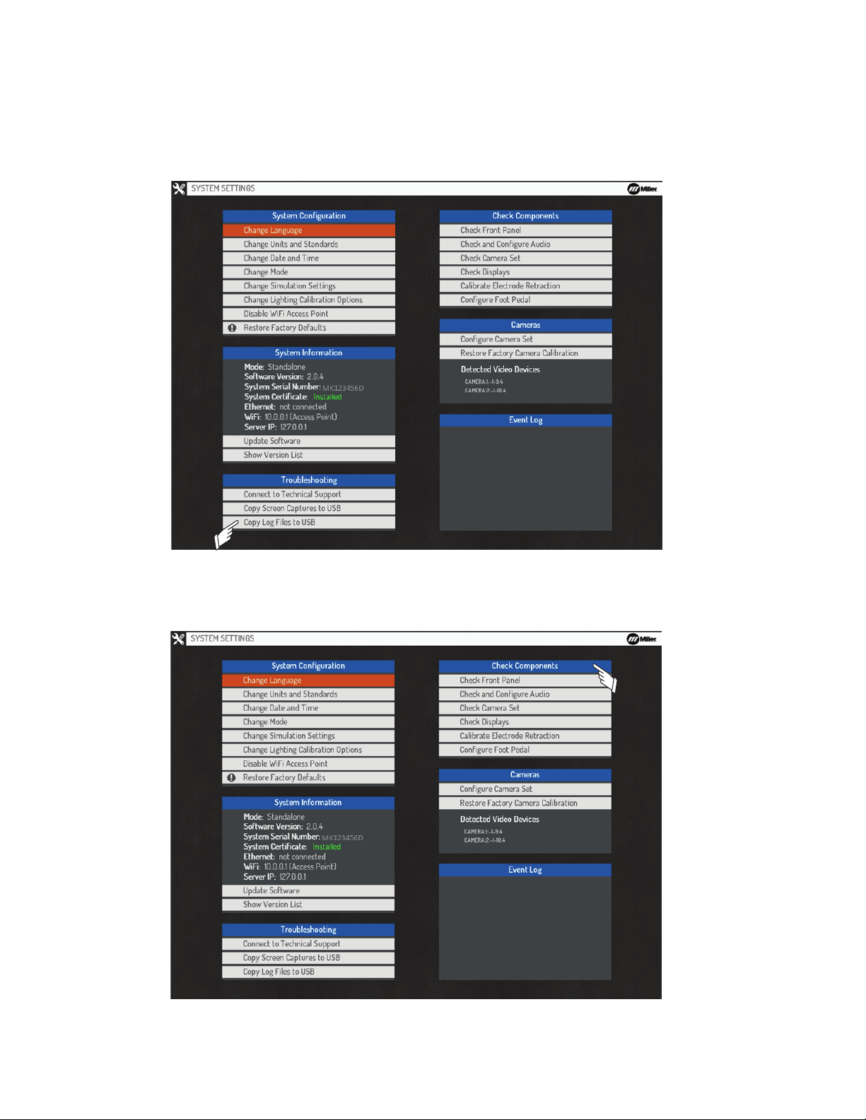
8-4. Troubleshooting
Figure 8-6. Software Update Confirmation Message
Figure 8-6. Software Update Confirmation Message
Figure 8-7. Connecting To Miller Technical Support
Select Connect to Technical Support and press OK to allow Miller technical support personnel to access the system for troubleshooting (Figure 8-7). Select Yes (to request assistance) or No (to cancel request for assistance), and then press OK. Press Cancel to exit the menu without
saving.
Select this option only if instructed by Miller technical support.
F
Select Copy Log Files to USB if you recently experienced a system issue or software crash. This will save the log files to a USB drive connected to the USB port located on the rear of the system.
Figure 8-7. Connecting To Miller Technical Support
8-5. Check Components
Figure 8-8. Check Components
OM-278680 Page 41
Page 46
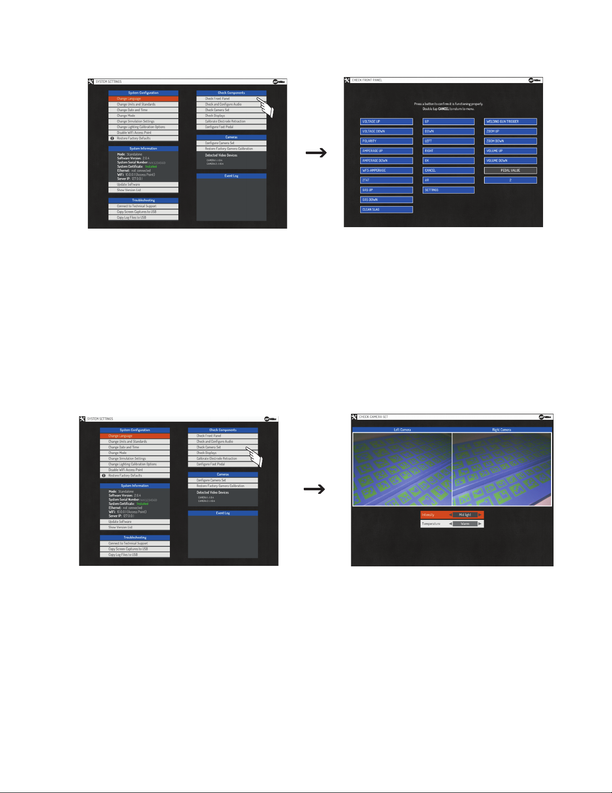
A. Checking Front Panel Functions
Figure 8-9. Checking Simulator Front Panel Controls And Gun/Torch Triggers
Select Check Front Panel and then press OK to access test screen (Figure 8-9). Use test screen to verify all front panel buttons and the MIG
Gun/TIG torch triggers are functioning properly. Quickly press Cancel twice to exit the menu.
Figure 8-9. Checking Simulator Front Panel Controls And Gun/Torch Triggers
B. Checking And Configuring Audio
Select Check and Configure Audio to select device(s) to be used for audio output and to verify proper function of the audio components. Press
Cancel to apply settings and exit the Menu.
C. Checking Displays
Select Check Displays to verify proper function of the simulator and helmet displays. When this option is selected, a solid white screen should
appear on both displays. Press Cancel to exit the Menu.
D. Checking Camera Set
Select Check Camera Set to verify the left and right cameras are functioning properly (Figure 8-10). Press OK.
Do not make video adjustments unless instructed by Miller technical support.
F
Figure 8-10. Checking Camera Set
OM-278680 Page 42
Page 47
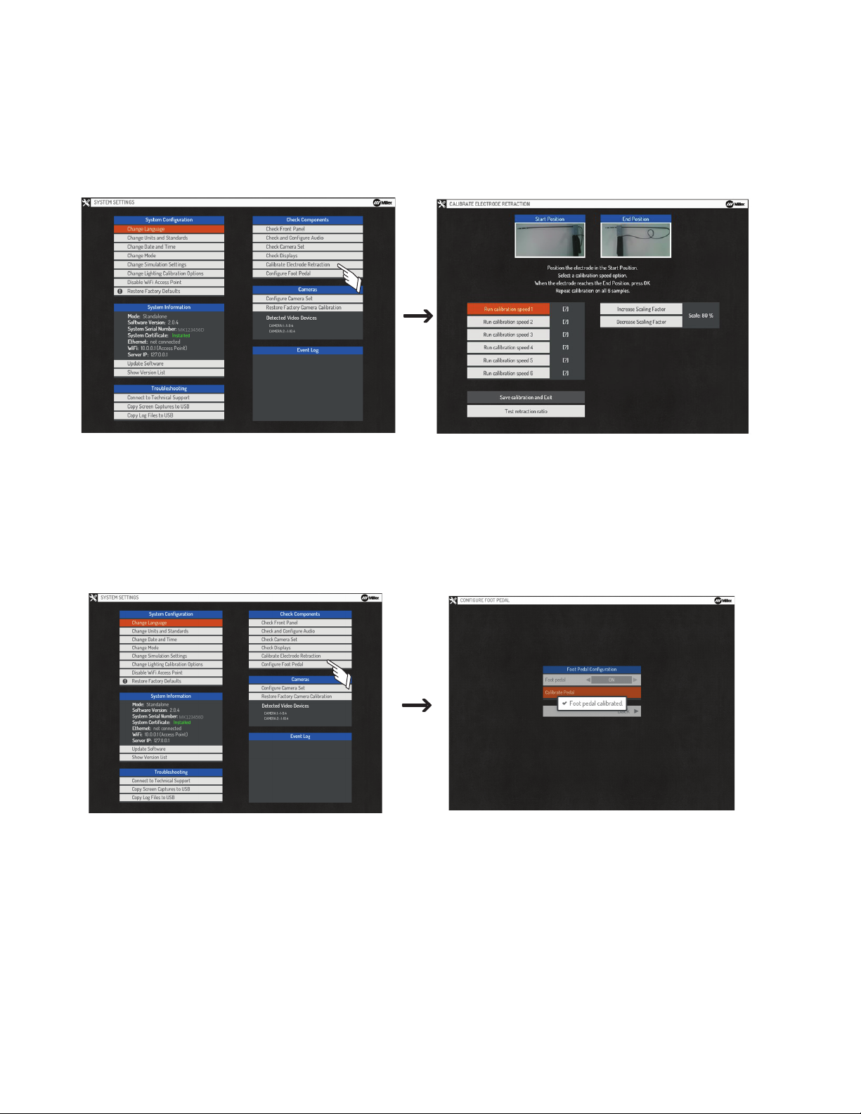
E. Calibrating Electrode Retraction
Figure 8-9. Checking Simulator Front Panel Controls And Gun/Torch Triggers
Figure 8-10. Checking Camera Set
Select Calibrate Electrode Retraction (Figure 8-11) and press OK to perform the following functions for the AR Stick electrode:
l Recalibrate the electrode retraction rate. (Recalibrate electrode retraction rate only when instructed by Miller technical support.)
l Test electrode retraction functionality.
l Adjust the electrode rate scaling factor. The retraction rate depends on the parameters of the exercise but the rate can be scaled to be slow-
er (80%) or faster (120%), as desired. To adjust the scaling factor, select Increase Scaling Factor or Decrease Scaling Factor, and then
press OK to change the value. Press OK after making changes, or press Cancel to exit the menu without saving.
Figure 8-11. Calibrating Stick Electrode
F. Configuring TIG RJ45 Foot Pedal
Select Configure Foot Pedal (Figure 8-12) and press OK to enable the TIG foot pedal (optional). Set foot pedal to ON, select Calibrate Pedal,
and follow on-screen instruction until the process is complete. See Section 5-14for foot pedal connections.
When the foot pedal is enabled, TIG welding exercises will require the use of the foot pedal. In order to use the TIG torch trigger button, the
F
foot pedal must be disabled.
Figure 8-12. Configuring TIG Foot Pedal
OM-278680 Page 43
Page 48
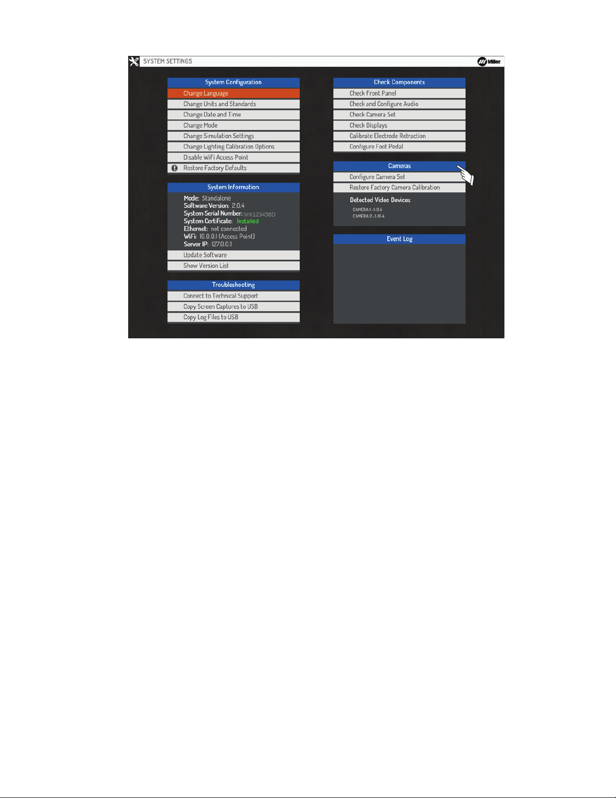
8-6. Cameras
Figure 8-13. Camera Settings
OM-278680 Page 44
Page 49
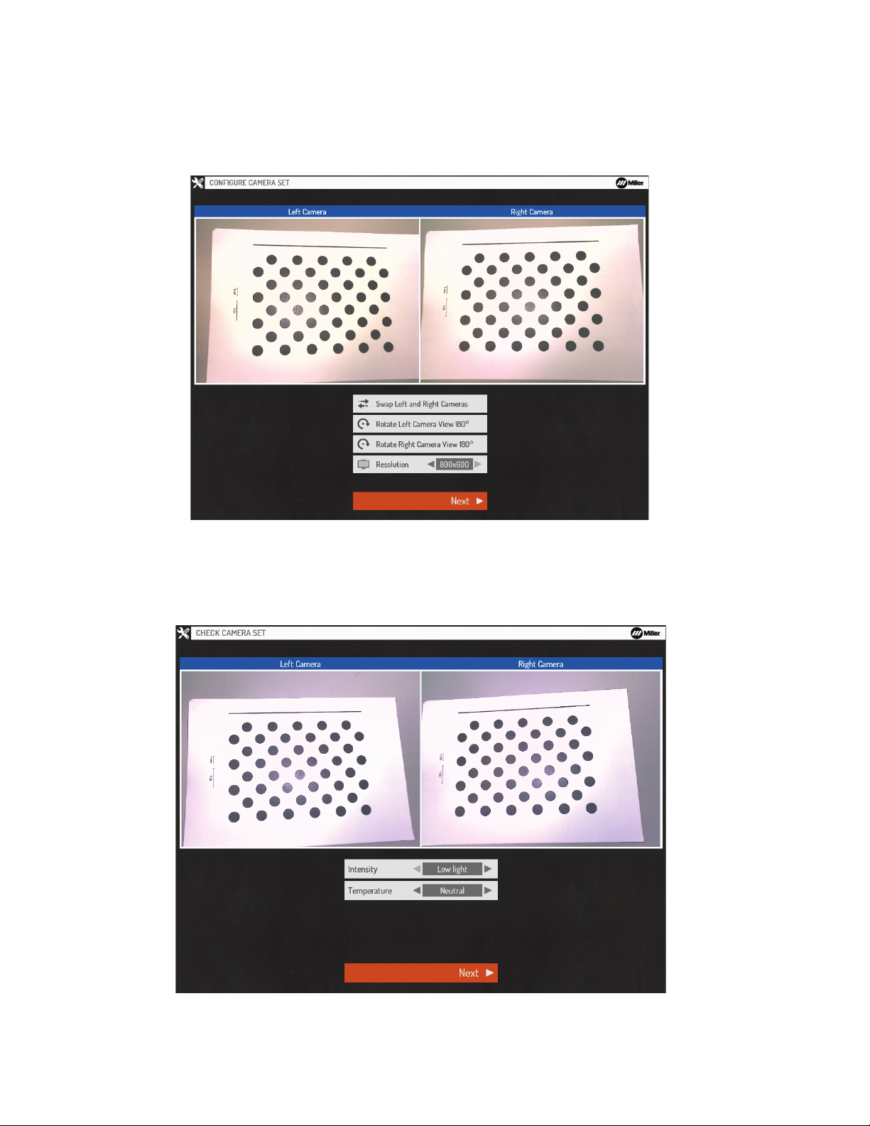
A. Configure Camera Set
Figure 8-13. Camera Settings
Selecting Configure Camera Set begins the processes required to calibrate the helmet’s cameras. The processes include Configure Camera
Set, Check Camera Set, Focusing Cameras, and Calibrating the Cameras.
Confirm the left and right camera views are displayed properly (Left and right are from the perspective of the user wearing the helmet). If the
camera views are swapped, select Swap Left and Right Cameras. If the left or right camera view is rotated, select the appropriate options to rotate the left or right camera to its proper orientation. The resolution can also be changed, but 800x600 will provide for the most consistent and accurate tracking experience. Select Next to proceed.
Figure 8-14. Configuring Camera Set
1. Check Camera Set
Adjust the Intensity and Color Temperature as needed until the displayed images closely match how they appear in the real world. Select Next
to proceed.
Figure 8-15. Checking Camera Set
2. Auto-Focus Cameras
Locate the camera calibration sheet (supplied with the simulator and also available to print from the AugmentedArc product website). Place it on
OM-278680 Page 45
Page 50
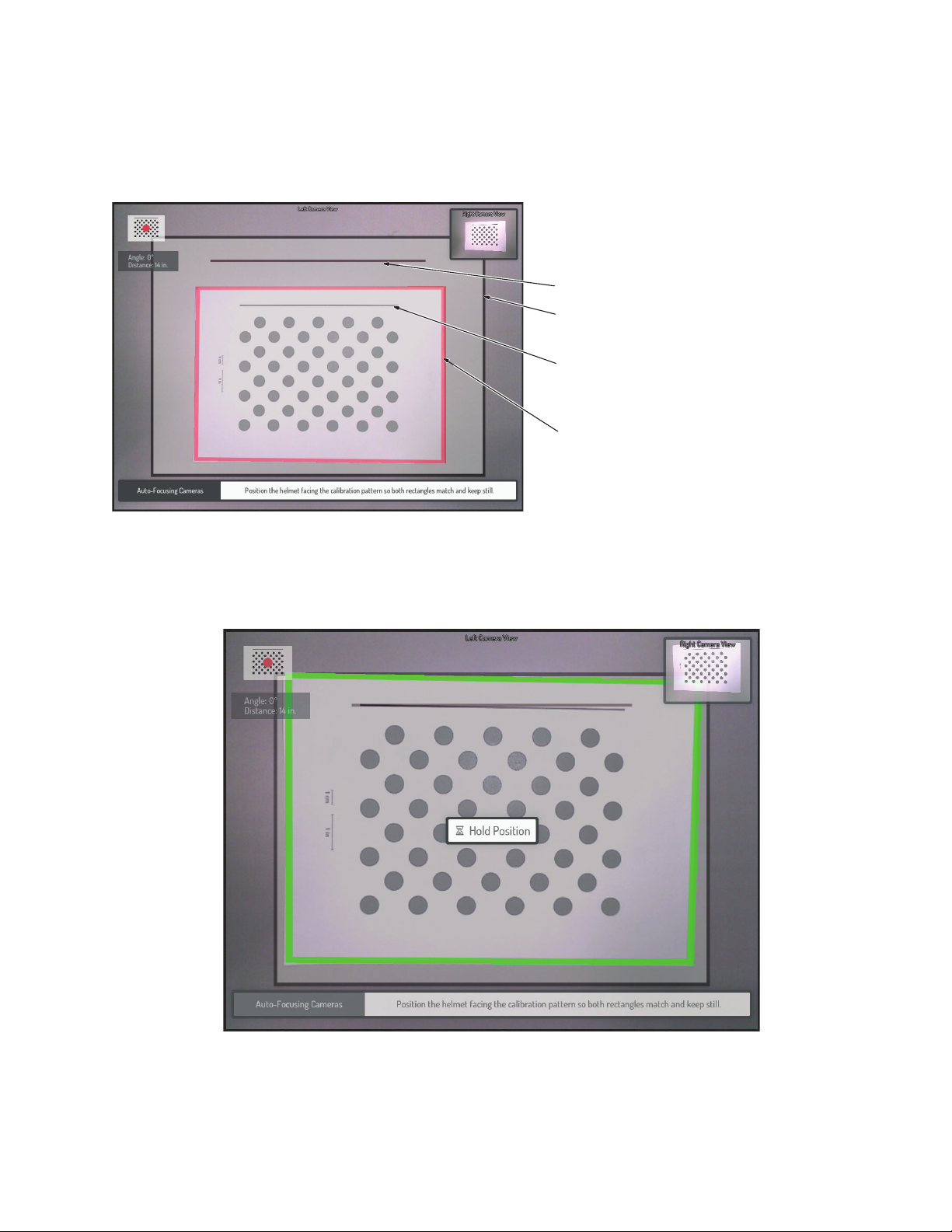
a flat surface. Hold the helmet over the calibration sheet so that the helmet cameras are facing straight down. Orient the helmet so that the Align-
Figure 8-15. Checking Camera Set
1
2
3
4
ment Guide Reference Line and the Calibration Sheet Reference Line are aligned. Move the helmet closer to or farther from the calibration sheet
until the Alignment Guide Border and the Calibration Sheet Border match (This should occur when the helmet is about 14 in. away from the calibration sheet).
It may be easiest to achieve proper helmet alignment while wearing the helmet and looking at the helmet display.
F
If printing calibration sheet, verify printed measurements are accurate using a ruler or tape measure.
F
1 Alignment Guide Reference Line
2 Alignment Guide Border
3 Calibration Sheet Reference Line
4 Calibration Sheet Border
Figure 8-16. Auto-Focus Cameras
When the helmet is positioned properly, the border of the calibration sheet will turn green and a message will appear that says Hold Position.
Hold the helmet still for a few seconds until the auto-focus process is completed. After completion, it will automatically proceed to the next
screen.
Figure 8-17. Hold Position
3. Confirm Focus
While keeping the helmet in the same position and orientation, the display will show the Left Camera’s view of the calibration sheet. Observe the
calibration sheet dots. If there is any perceived blur, press Cancel and repeat the auto-focus process. If they appear to be in focus (without any
significant blur), press OK to proceed. On the next screen, repeat the process for the Right Camera.
OM-278680 Page 46
Page 51
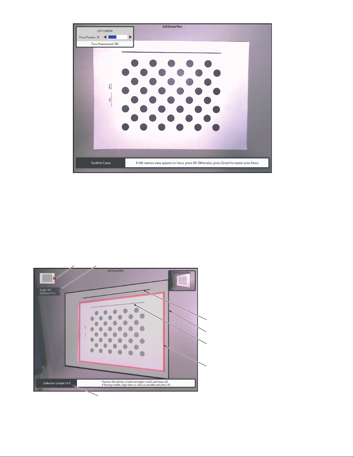
Figure 8-17. Hold Position
Figure 8-18. Confirming Focus
1
2
3
4
5
6
7
4. Capture Calibration Samples
To calibrate the helmet, you will be required to capture eight samples with the helmet facing the calibration sheet at a variety of orientations and
distances. For each sample, note the Helmet Position Direction arrow displayed in the upper left corner. Hold the helmet facing the calibration
sheet in the indicated direction. Orient the helmet so that the Alignment Guide Reference Line and the Calibration Sheet Reference Line are
aligned. Adjust the helmet distance, orientation, and position until the Alignment Guide Border and the Calibration Sheet Border match.
It may be easiest to achieve proper helmet alignment while wearing the helmet and looking at the helmet display.
F
If you have trouble aligning the reference lines exactly, align them as close as possible and press OK to manually trigger the sample
F
capture.
1 Alignment Guide Reference Line
2 Alignment Guide Border
3 Calibration Sheet Reference Line
4 Calibration Sheet Border
5 Helmet Position Direction
6 Helmet Position Information
7 Calibration Sample Number
Figure 8-19. Capturing Calibration Samples
OM-278680 Page 47
Page 52
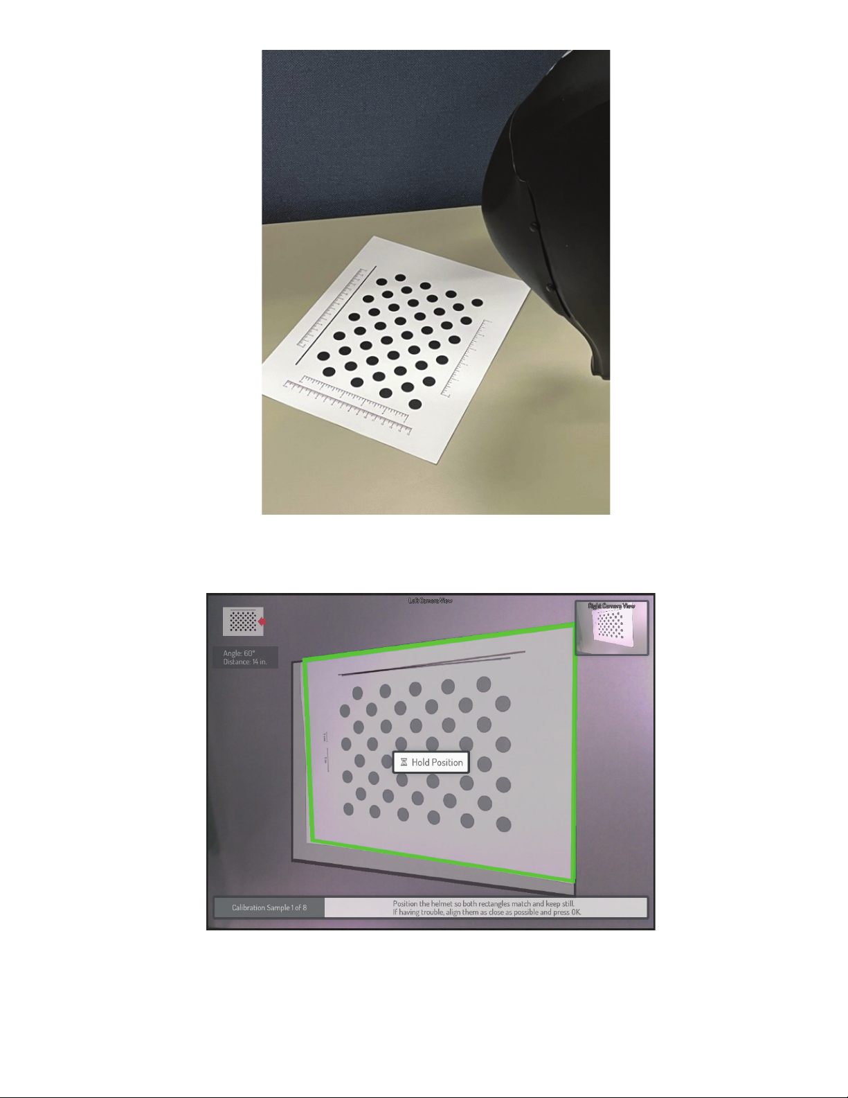
Figure 8-20. Helmet In Proper Position For Capturing Calibration Sample 1
When the helmet is positioned properly, the border of the calibration sheet will turn green and a message will appear that says Hold Position.
Hold the helmet still for a few moments until the calibration sample is captured. After completion, it will automatically proceed to the next sample.
For each sample, note the Helmet Position Direction and position the helmet accordingly.
Figure 8-21. Hold Position
After all eight samples are successfully captured, the results are displayed. If the results indicate a successful calibration, select Save Calibration. If the results indicate a failed calibration, this may be due to helmet movement or improper positioning during the capture of one or more of
the calibration samples. In this case, select Start Calibration to repeat the calibration process.
If the process of successfully capturing the required samples proves too difficult, there is an option to change the resolution to 640x480
F
(see 8-14). At this resolution, the calibration process is simpler. However, using this lower resolution setting will not have the tracking
OM-278680 Page 48
Page 53
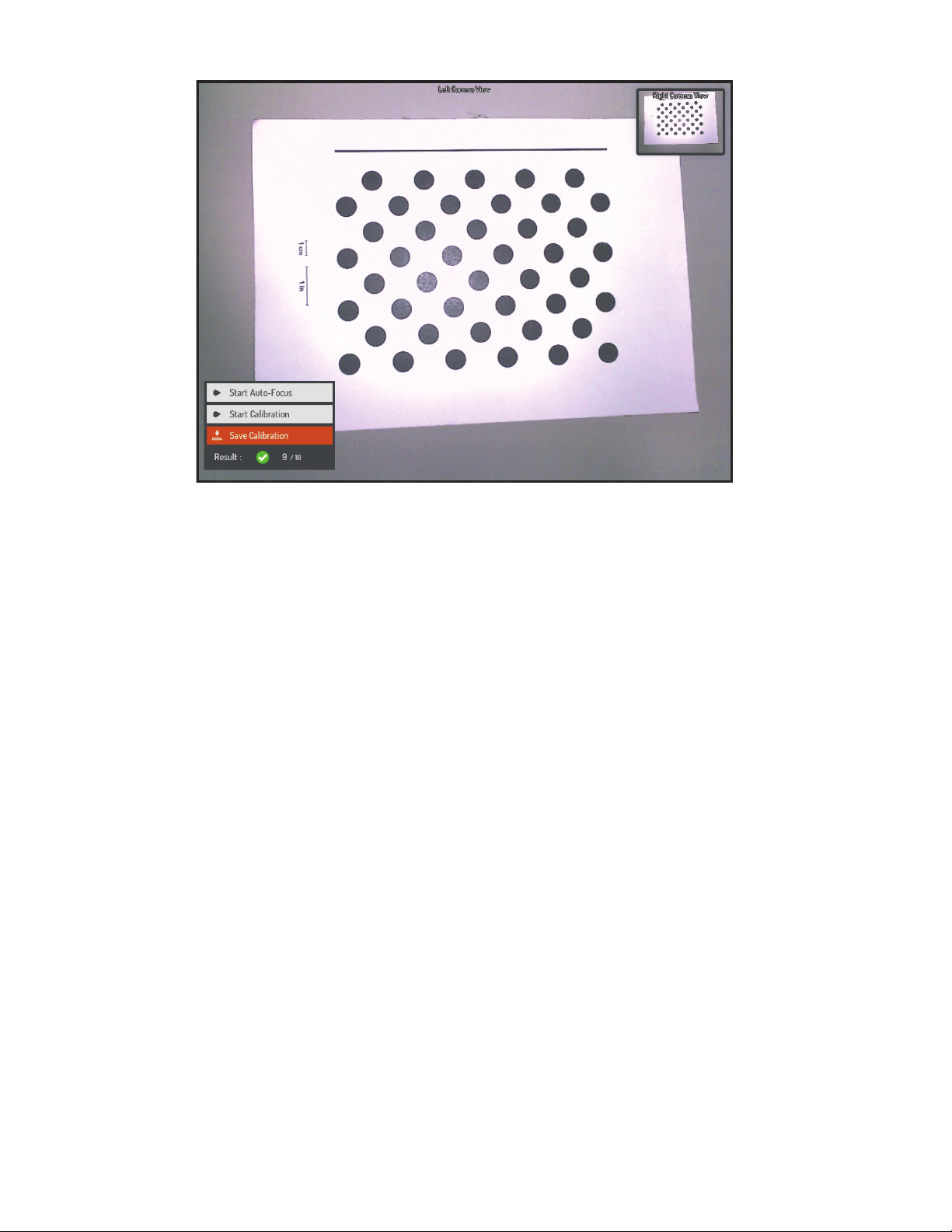
benefits of the higher resolution setting.
Figure 8-21. Hold Position
Figure 8-22. Calibration Results
B. Restore Factory Camera Calibration
Selecting Restore Factory Camera Calibration will replace the current calibration data with the original data capturing during factory calibration. Do this only as directed by Miller technical support.
OM-278680 Page 49
Page 54
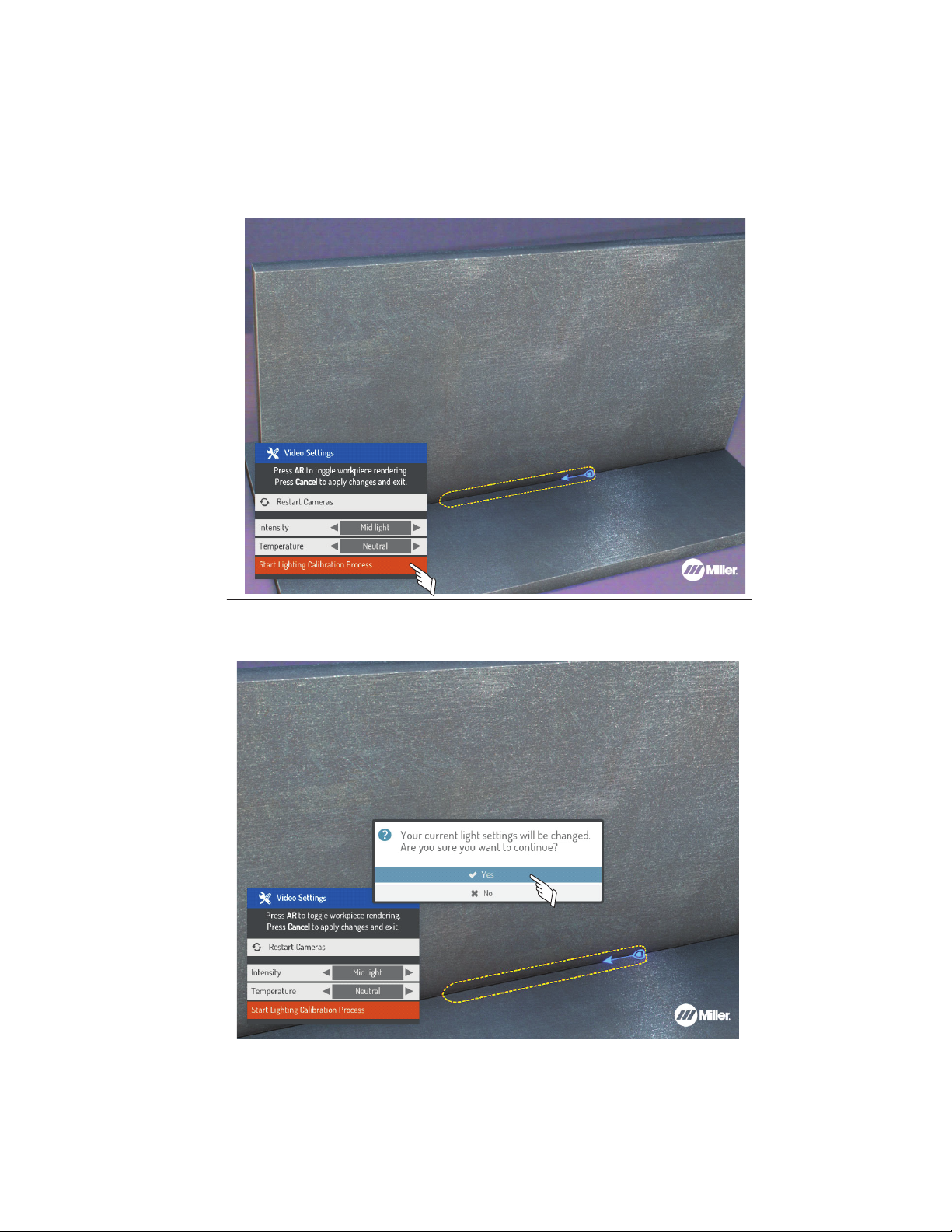
8-7. Video Device Settings
Figure 8-23. Video Device Lighting Calibration
The video device settings may need to be adjusted for specific lighting conditions to optimize the AR tracking. To access the Video Settings
menu, press the Settings button on the front panel after an exercise has been started.
A. Lighting Calibration
The video settings can be automatically adjusted for the room lighting conditions using the Lighting Calibration feature. This process removes
the guesswork from the process and usually results in the settings being optimized for tracking.
To begin the process, select Start Lighting Calibration Process and press OK.
Figure 8-23. Video Device Lighting Calibration
When prompted, select Yes and follow the on-screen instructions (see Section 7-2).
Figure 8-24. Lighting Calibration Confirmation Prompt
OM-278680 Page 50
Page 55
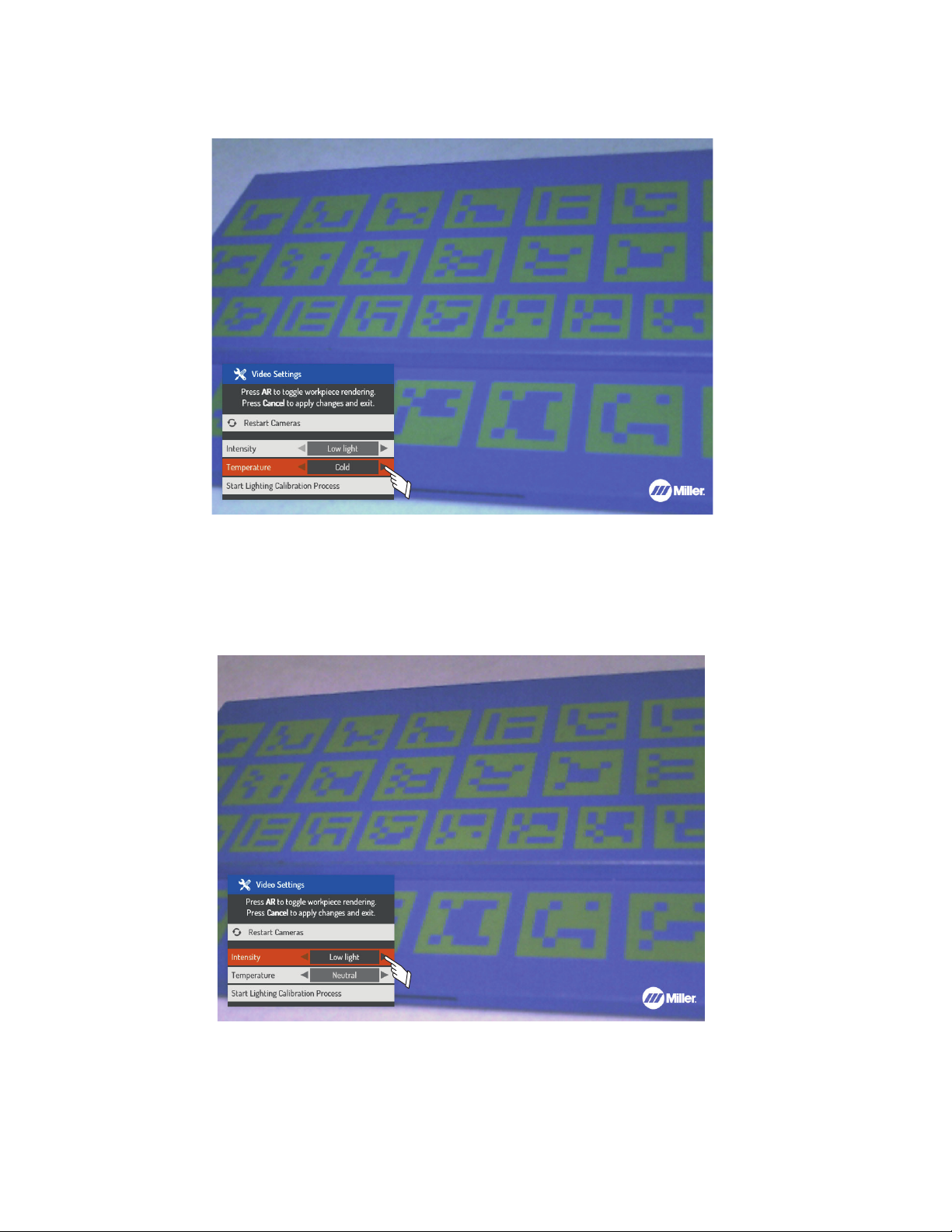
B. Temperature Setting
Figure 8-25. Changing Temperature Setting
Use the up/down Navigation buttons to select the Temperature setting. Use the left/right Navigation buttons to select either Cold, Neutral, or
Warm. Choose the setting that corresponds to the color of light in the room (cold = bluish, neutral = white, warm = yellow). If the Lighting Calibra-
tion process fails to result in the best settings, they can be adjusted manually. See Figure Figure 8-25.
Figure 8-25. Changing Temperature Setting
C. Intensity Setting
Use the up/down Navigation buttons to select the Intensity setting. Use the left/right Navigation buttons to select either Low Light, Mid Light,
or High Light. Choose the setting that corresponds to the intensity of light in the room. See Figure Figure 8-26.
If AR tracking is working properly, select Cancel to apply the changes and exit.
Figure 8-26. Changing Intensity Setting
OM-278680 Page 51
Page 56
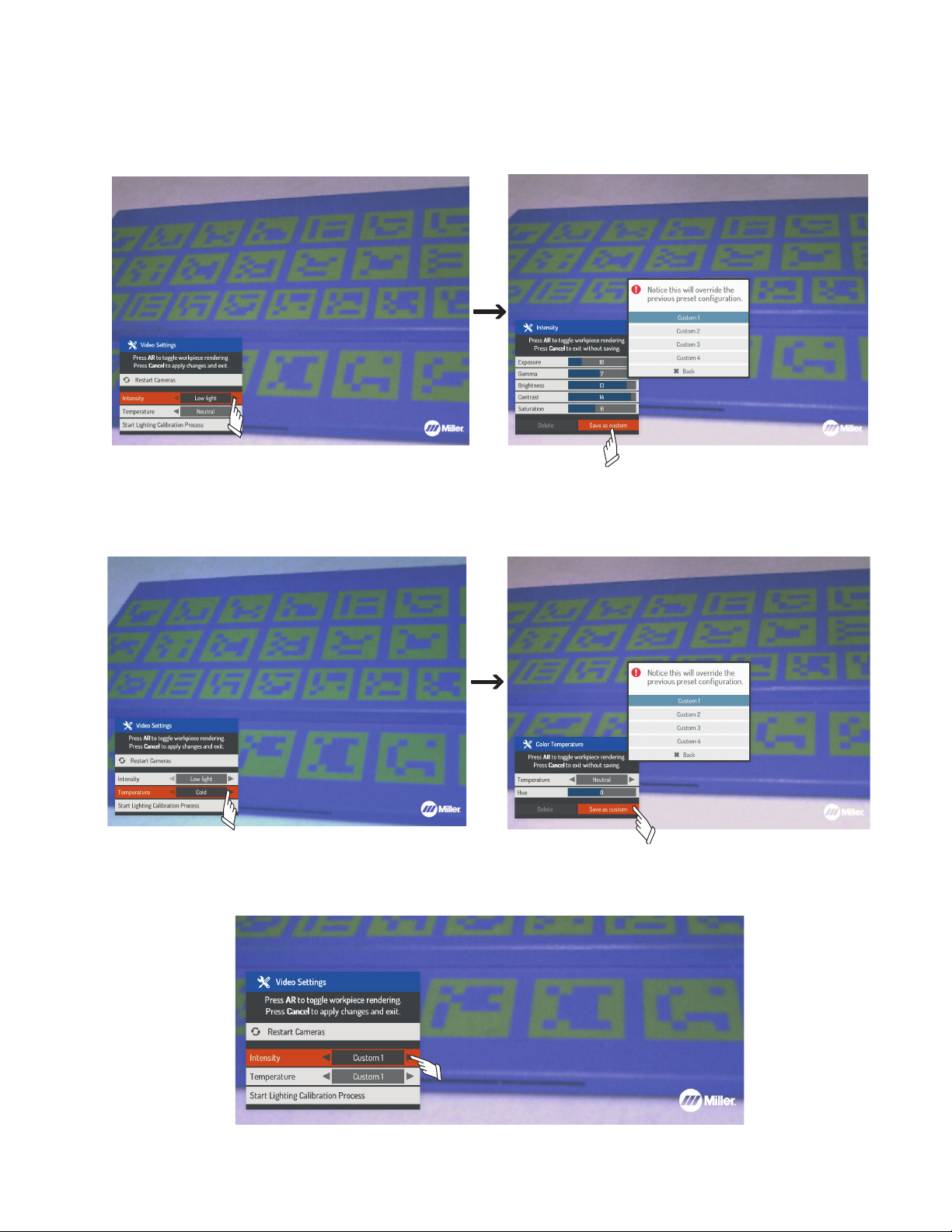
D. Custom Settings
Figure 8-27. Creating Custom Light Intensity Setting
Figure 8-27. Creating Custom Light Intensity Setting
Figure 8-28. Creating Custom Light Temperature Setting
If the existing options for lighting intensity and temperature do not resolve AR tracking issues, custom settings can be created.
To create a custom Light Intensity setting, use the up/down arrows to select the light intensity setting, and press OK (Figure 8-27). Use the up/
down Navigation buttons to scroll to a light intensity setting (Exposure, Gamma, Brightness, etc.), and then use the left/right Navigation buttons
to adjust. After the desired light intensity values are set, select Save as custom and press OK, or press Cancel to exit the menu. Choose the
name of the custom setting (Custom 1, Custom 2, Custom 3) to save the current intensity values.
Figure 8-27. Creating Custom Light Intensity Setting
To create a custom Light Temperature setting, use the up/down arrows to select the temperature setting, and press OK (Figure 8-28). Use the
left/right Navigation buttons to adjust the Hue value. After the desired hue value is set, select Save as custom and press OK, or press Cancel to
exit the menu. Choose the name of the custom setting (Custom 1, Custom 2, Custom 3) to save the current temperature value.
Figure 8-28. Creating Custom Light Temperature Setting
To apply a custom intensity or temperature setting, use the up/down and left/right Navigation buttons to scroll to the desired custom option for
each setting and then press Cancel to apply the changes and exit (Figure 8-29).
OM-278680 Page 52
Figure 8-29. Applying Custom Settings
Page 57
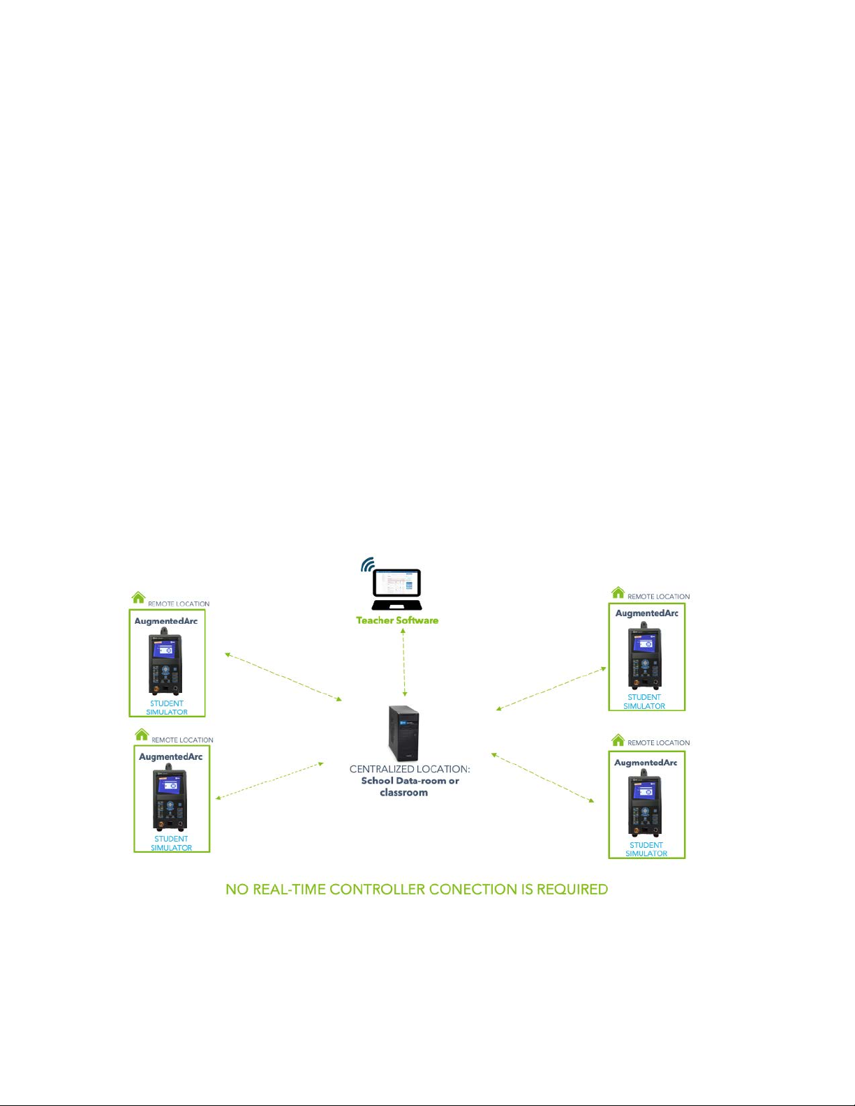
8-8. Distance Learning Mode
The Distance Learning mode works similarly to the Classroom mode (many simulators working together and connected to a controller/server).
However, the simulators can work disconnected from the controller if needed, and be placed in a location away from the controller to allow students to work remotely. When the simulators are returned to the same location as the controller (classroom) and they are synced together, the instructor can use the Teacher software to review the progress of the students.
If real-time student progress must be evaluated while the simulators are at a remote location (different location than the controller), the controller
and simulators must be configured to be accessible over the internet. Special network requirements are needed for the controller. Contact Miller
technical support for assistance.
A. Connecting For Distance Learning Mode
School requirements:
l Controller (server)
l Router (supplied with controller)
l Internet connection is not required
Student requirements:
l Simulator (AugmentedArc)
Connection information:
l Allow 5-10 minutes for connections
l Internet connection is not required
l IT assistance is not required
l One-time configuration
l Activity synchronization with the controller is done when the student returns the simulator to the school (if not connected to the internet).
l Virtual classroom is not available if system has no internet connection.
l Virtual Classroom is available only if the school and student have internet access and the procedure indicated by Miller technical support
has been followed.
Figure 8-30. Distance Learning Mode Connections
OM-278680 Page 53
Page 58
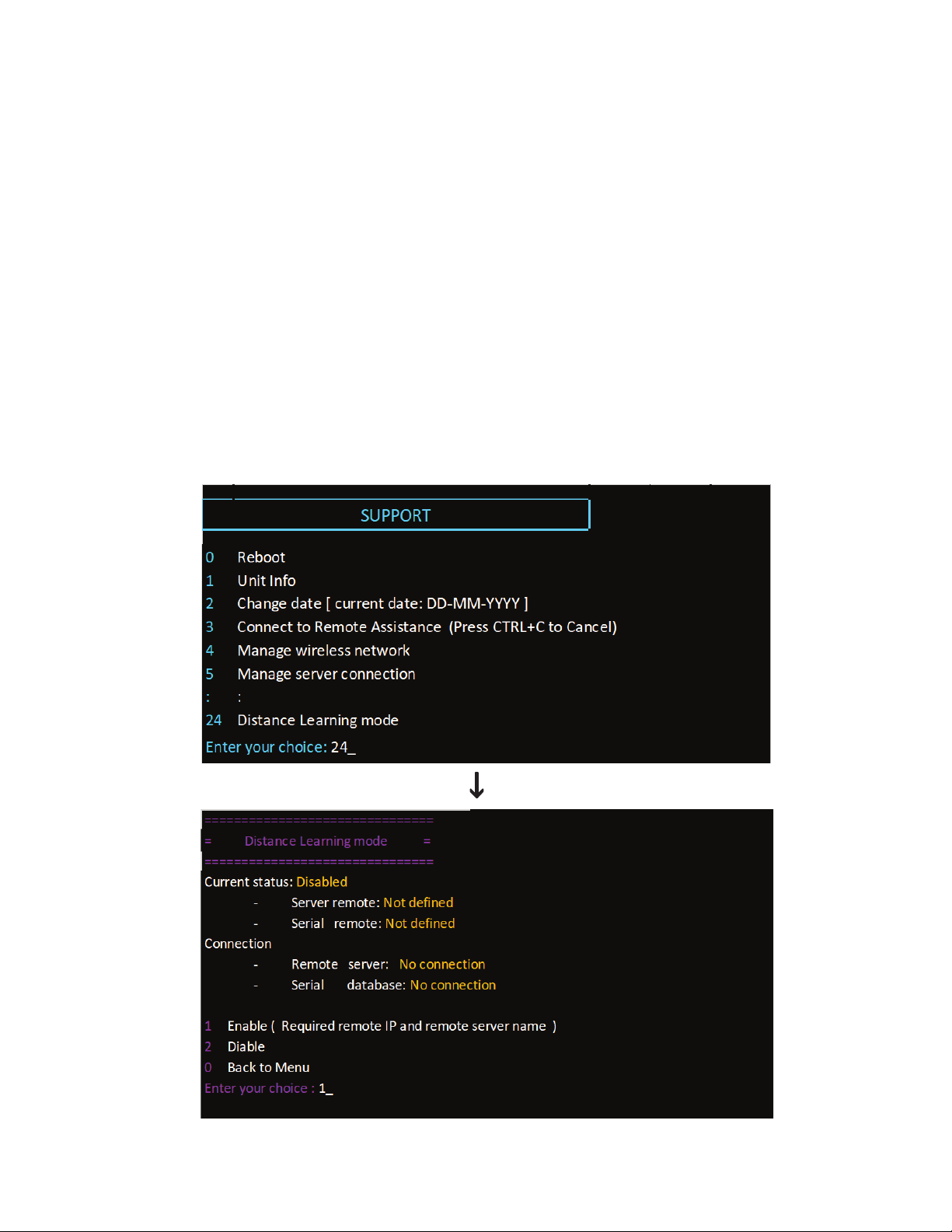
B. Enabling Distance Learning Mode In The Simulator
Tools needed:
l USB keyboard
Requirements:
l Controller must be turned on.
l The network between the simulators and controller must be connected, using either the supplied router (WiFi or wired) or local network.
l If using the supplied router, it must be turned on.
Connection procedure for each simulator (Figure 8-31):
l Configure simulator in Stand-alone mode. New units can be configured as Stand-alone during initial setup. If unit is already in Classroom
mode, log in as administrator, access System Settings, and change mode to Stand-alone (see Sections 8-1 and 8-2).
l After simulator is configured as Stand-alone, connect a USB keyboard to the back of the unit.
l Access Support menu by pressing CTRL + ALT + F4 keys.
l Select Distance Learning Mode option by entering 24 in the Enter your choice field. Press Enter.
l Select option Enable (Required remote IP and remote server name) by entering 1 in the Enter your choice field.
l Enter the Remote Server IP address:
If the controller is not accessible over the internet or it has not been assigned a static IP address by the user to access their own network, and
the customer is using the supplied router, then enter the default IP (10.0.0.1).
If the controller is accessible over the internet and using a public IP address or it has been assigned a static IP address by the user to access
their own network, enter the static IP address that the institution’s IT department configured for the controller (no real-time progress), or the public IP address of the network where the controller is installed (real-time progress).
OM-278680 Page 54
Figure 8-31. Configuring Simulator(s) For Distance Learning Mode
Page 59
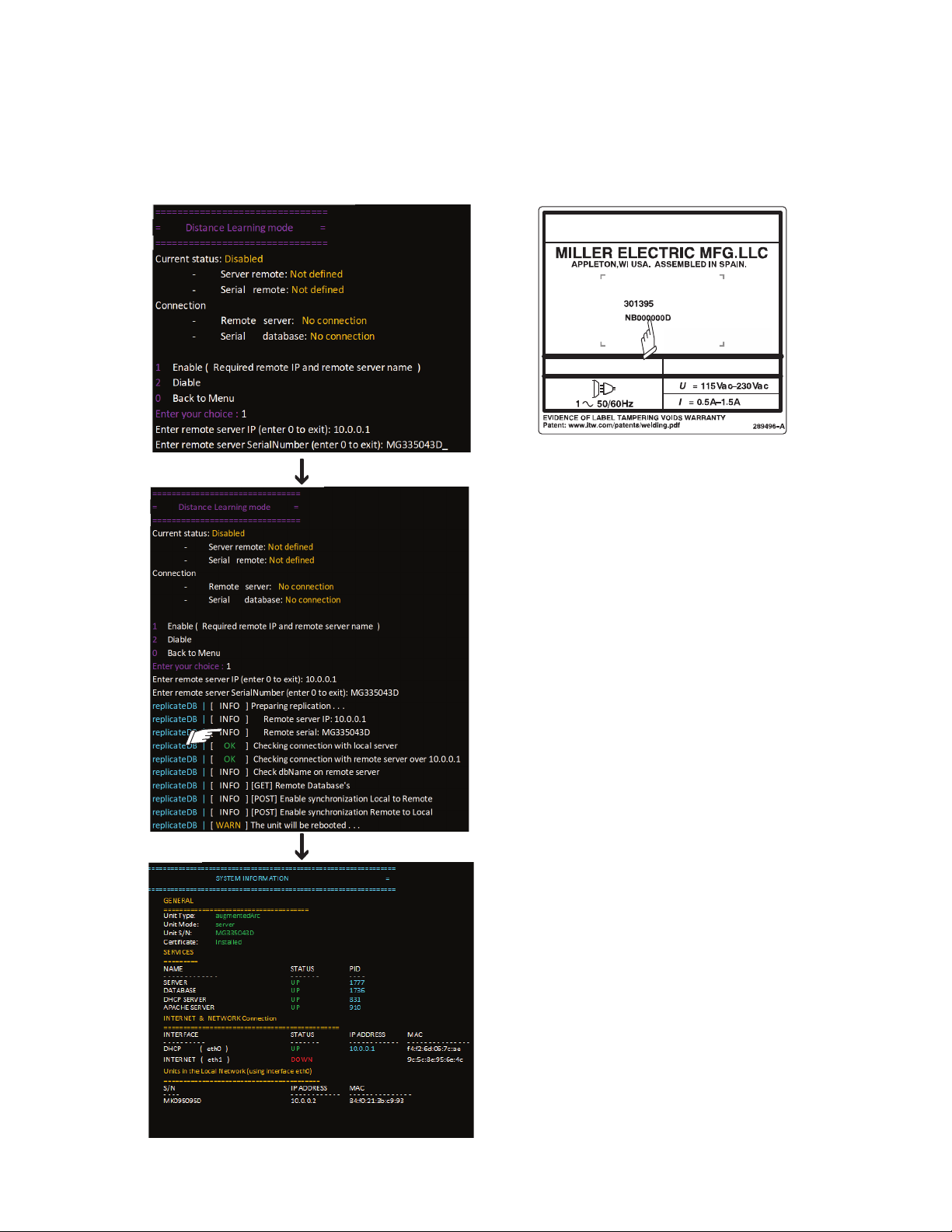
l Enter the serial number of the controller in the Remote Server SerialNumber field and press Enter. (The serial number is located on the
Controller serial
number
right side of the controller.)
l If the configuration was successful, before the simulator reboots the two Checking connection… messages will be marked OK.
l After the simulator reboots, it will automatically sync with the controller the first time with the new Distance Learning configuration and it will
be displayed as a unit connected in the controller. In this example, the simulator MK095095D is displayed under the units in the local network (using interface eth0) with an IP address 10.0.0.2.
l The simulator can now be used at the same location as the controller (school) or can be used off-site if desired (student’s home). Repeat
the previous steps for all the simulators.
Figure 8-32. Configuring Simulator(s) For Distance Learning Mode (Continued)
OM-278680 Page 55
Page 60

C. Syncing An Off-site Simulator With The Controller
When a simulator is taken off-site (student’s home), the progress information (exercises performed and quizzes taken) will be saved in the unit.
To see the student’s progress and save it with the progress reports of the entire class, the simulator must be returned to where the controller is located and then synced with the controller. Sync simulator(s) with controller as follows:
l Turn on controller.
l Connect network between simulator (s) and controller using either supplied router (WiFi or wired) or local network. If using the supplied
router, be sure it is turned on.
l Turn on simulator. The simulator will automatically sync with the controller and update the changes made.
OM-278680 Page 56
Page 61
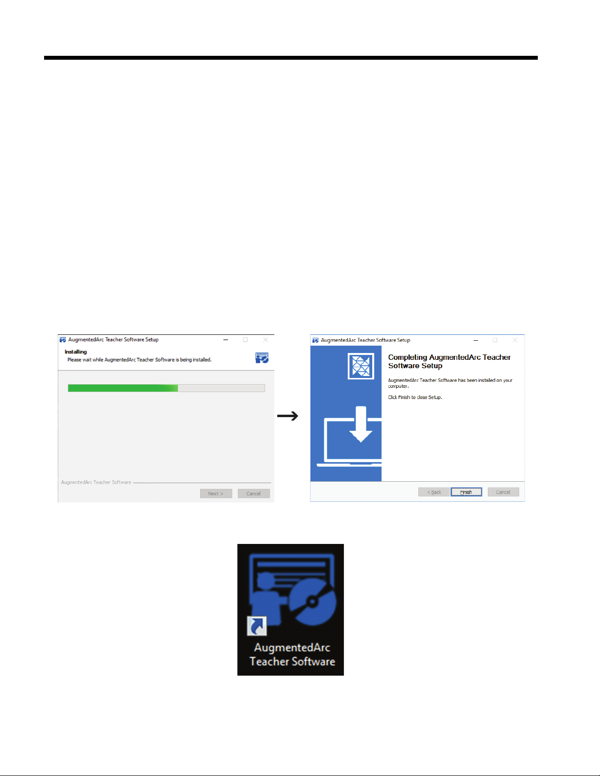
SECTION 9 – USING THE TEACHER SOFTWARE
SECTION 7 USING THE TEACHER SOFTWARE
9-1. Installing The Teacher Software Program
Download the teacher software from the Miller website at https://www.millerwelds.com/aasoftware
Computer requirements:
l Windows 7 (64 Bits), Windows 8 (64 Bits), Windows 10 (64 Bits)
l Processor: 2.2GHz 3MB
l RAM: 4GB
l Graphics:
– 2GB VRAM DirectX 9 compatible graphics card
– NVidia GeForce 750 or better
– GeForce 900 Mobile series or better
– AMD Radeon HD 6000 series or better, or Radeon HD 7000 Mobile series or better.
l Display (min): 1366 x 768
l Hard Drive: 1GB
Installation Procedure
Double-click the AugmentedArc_TeacherSoftware installation file. The installation setup window appears) and the installation automatically begins. When the process is completed, click Finish (Figure 9-1).
Continue with the installation process, including the license agreement screen. A Teacher Software shortcut and a shortcut on the Windows taskbar will be created (Figure 9-2). Click Finish.
Figure 9-1. Teacher Software Installation Screens
Figure 9-2. Teacher Software Shortcut Icon
If using a router, connect the computer running the Teacher Software to the AUGMENTED-ARC network (Figure 9-3). If using the internal Access Point (see section 8-2), connect the computer to the AugmentedArc_XXXXXXXXX network (Figure 9-3), where the Xs are the serial number of the simulator (i.e. AugmentedArc_MK123456D). When prompted for the network security key, enter augmentedarc. After connecting to an
Access Point, it may take up to a minute before the connection is established and the Teacher Software can connect.
OM-278680 Page 57
Page 62
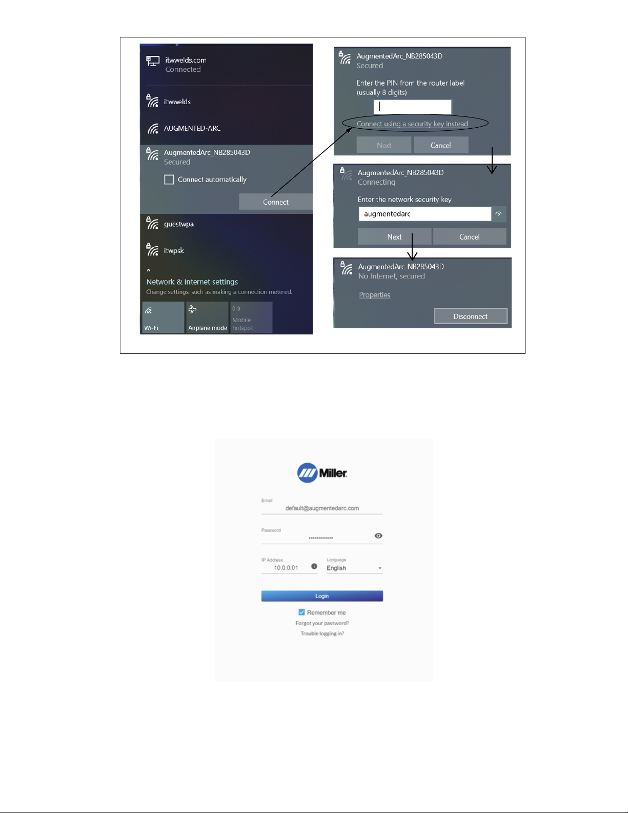
Figure 9-3. AUGMENTED-ARC Network Connection
Open Teacher Software on computer. The Login screen appears (Figure 9-4).
Available languages are English, Spanish, and French.
F
Click Trouble logging in? to see helpful videos on logging in.
F
Figure 9-4. Login Screen (Teacher Software)
For classroom configurations the IP address is always the same (10.0.0.1). To obtain the IP Address for standalone configurations, log in as administrator on AugmentedArc system. Press AugmentedArc Systems Settings Button (Section 6-1). System Settings screen displays Ethernet
IP address (Figure 9-5).
OM-278680 Page 58
Page 63
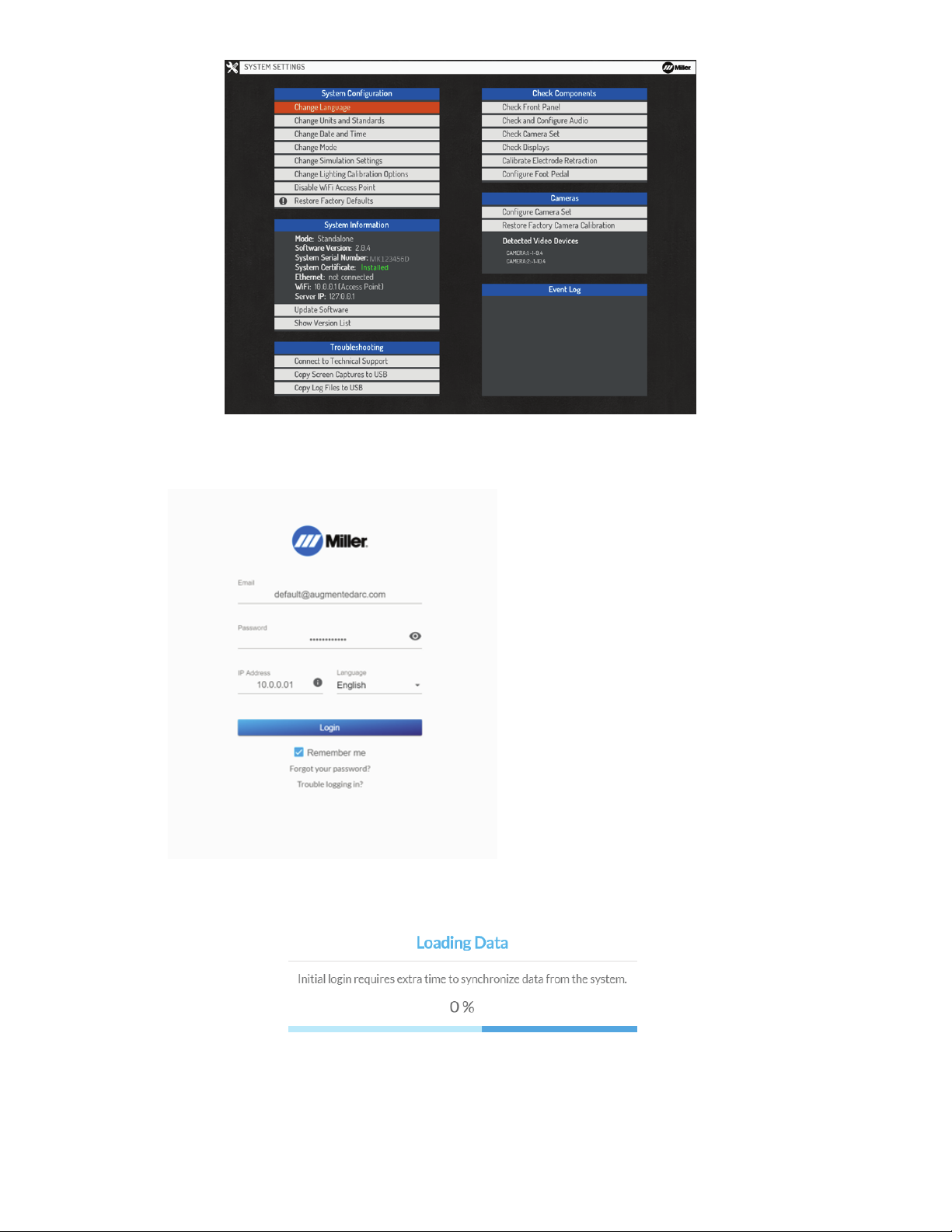
.
Figure 9-1. AUGMENTED-ARC Network Connection
Figure 9-5. System Settings Screen
.
Figure 9-6. Login Screen (Teacher Software)
Enter the user Email ([email protected]) and password (augmentedarc). Enter Ethernet IP address. Click Login.
Email is default@augmentedarc. com
F
and Password is augmentedarc. Email
and password are case sensitive.
For standalone configurations, enter the
F
Ethernet IP address shown on the simulator screen. For classroom configurations the IP address is always the same
(10.0.0.1).
Figure 9-6. Login Screen (Teacher Software)
When connecting to a system for the first time, the Teacher Software will synchronize offline data from the system which may take a few
minutes.
Figure 9-7. Initial Login Synchronization
After successfully logging in and connecting to a system, subsequently closing and re-opening the software will not require that you log in
F
again. You will only have to log in again if you intentionally log out.
OM-278680 Page 59
Page 64
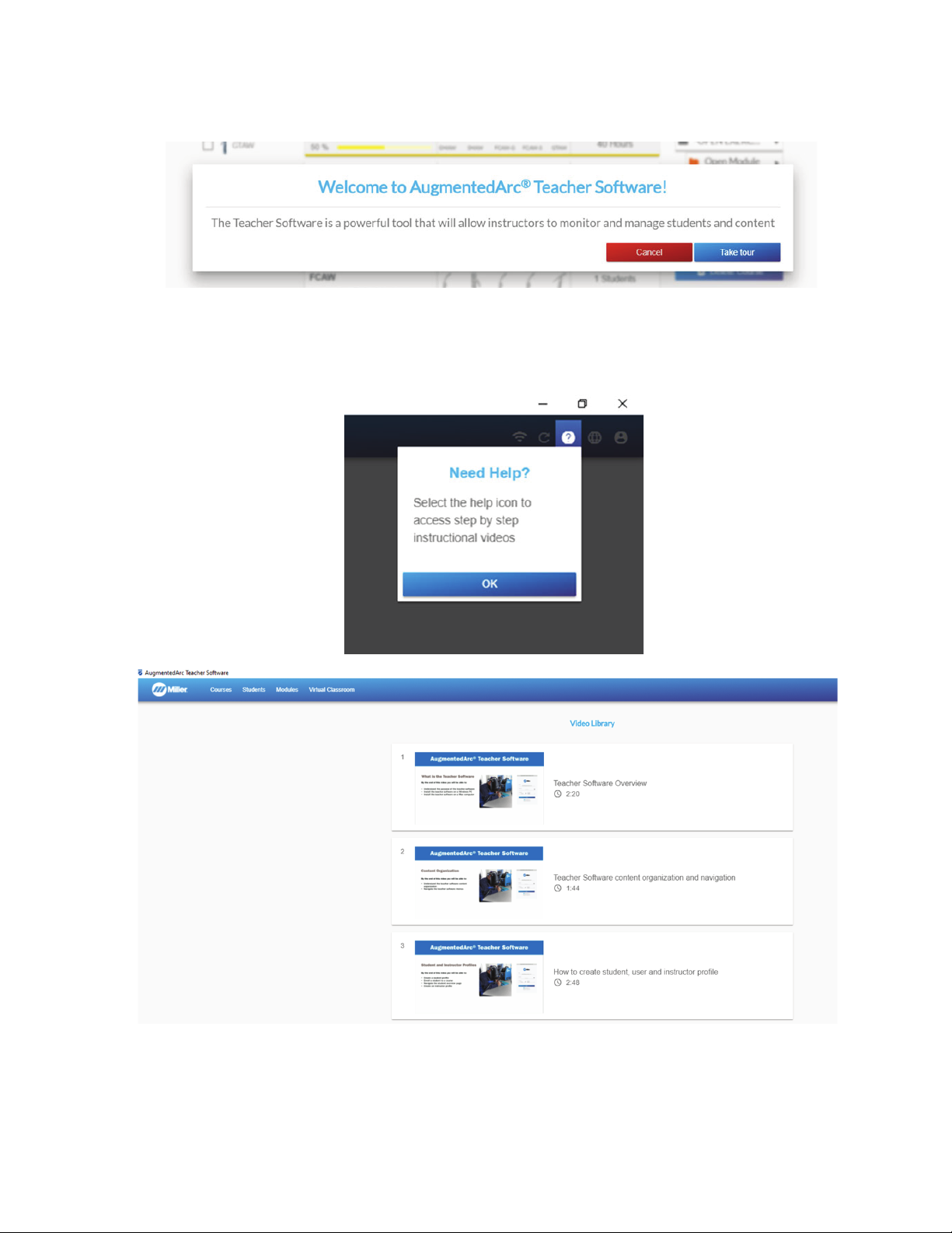
9-2. Instructional Help Videos
When entering the Teacher Software the first time, instructors have the option of touring the application. Click Take Tour to proceed.
Select the Help icon at any time to access instructional videos.
F
OM-278680 Page 60
Figure 9-8. Instructional Help Videos
Page 65
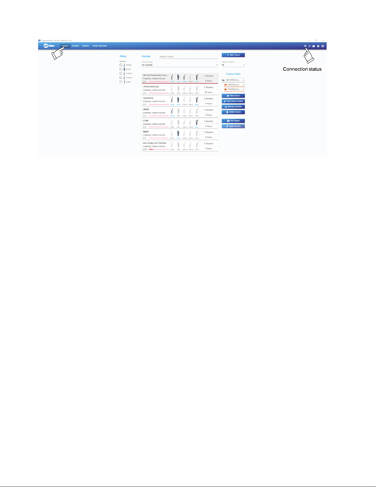
9-3. Using The Teacher Software
The navigation header contains options to select between the Course, Students, Modules, and Virtual Classroom sections of the software.
Figure 9-9. Teacher Software Navigation Header
As long as you do not log out, you can continue using the Teacher Software offline. The changes you make offline will be automatically ap-
F
plied to the simulator when you reconnect to the network.
OM-278680 Page 61
Page 66
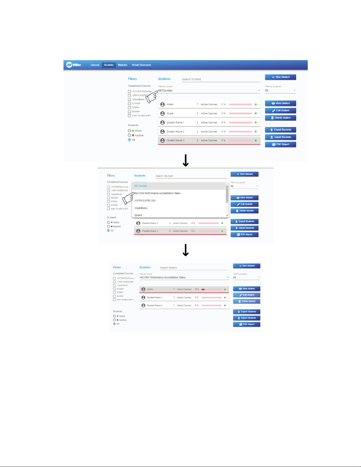
A. Student Home Page
A list of existing students is displayed in the middle of the screen. Select All Courses in the course filter to display all of the students. Select a
course to see a list of students assigned only to that course. Double-click a student to view the student overview.
The student overview shows the list of enrolled courses with associated progress and statistical analysis. Select Edit Student to edit the student’s profile. Select Manage Courses to add or remove the student from the list of available courses.
OM-278680 Page 62
Figure 9-10. Student Home Page
Page 67
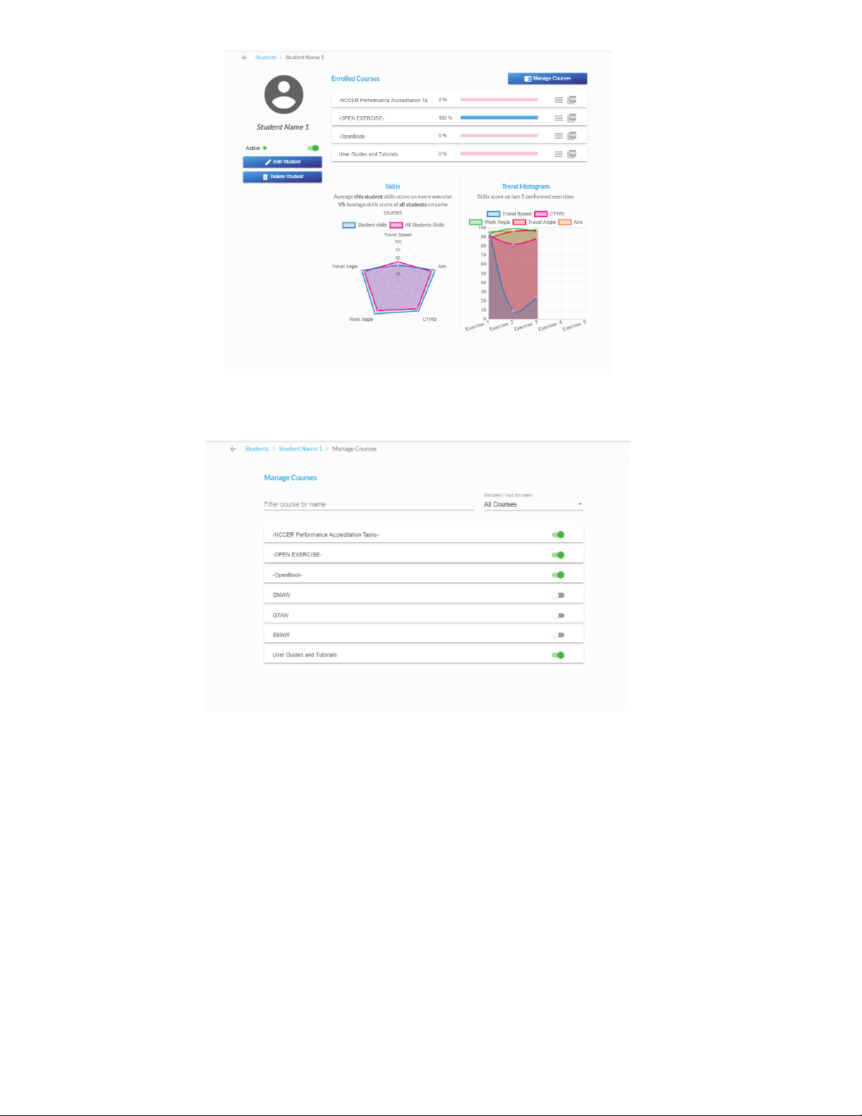
Figure 9-11. Student Overview Page
OM-278680 Page 63
Page 68
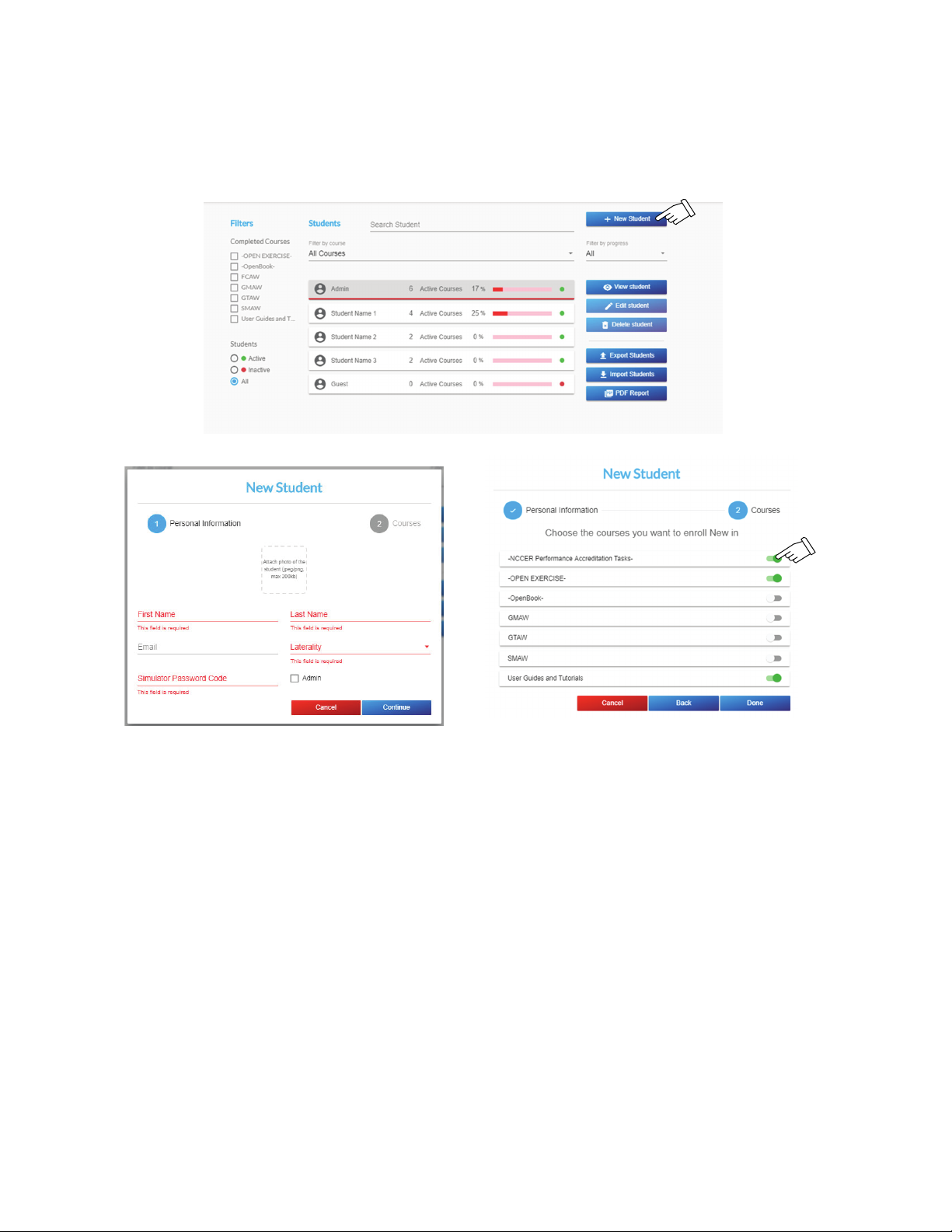
B. Adding A Student
Click + New Student and the student personal information entry screen is displayed. The Email is optional, but all other fields are required (only
numerals 1-4 can be used for Password). Assign a picture to a student by clicking the Attach photo box and then selecting the desired photo to
be added to the student profile. Click Continue and the course enrollment screen is displayed. Click the enrollment toggle button for each course
you want to enroll the student in. Click Done to save changes.
The student image must be in a .png format, and the file size cannot exceed 2Mb.
F
OM-278680 Page 64
Figure 9-12. Student Data Screen
Page 69
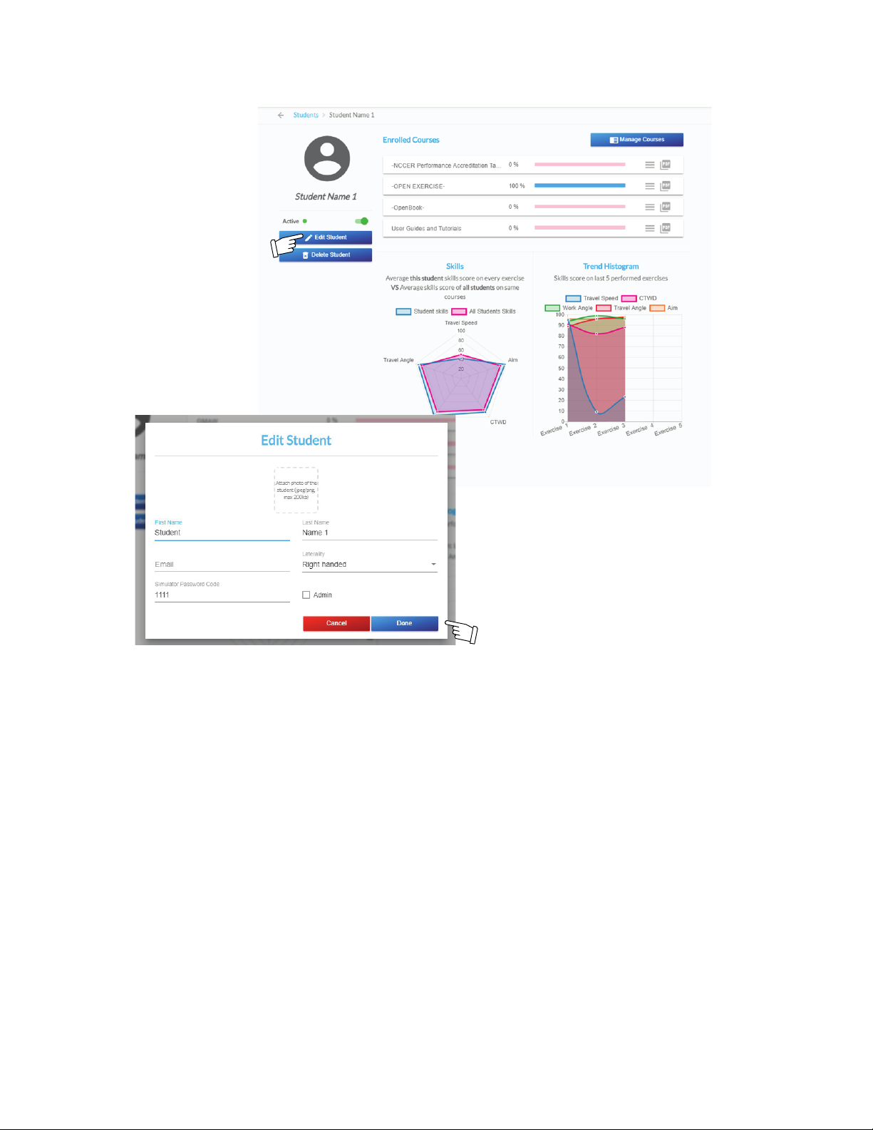
C. Editing Student Information
From the student overview screen of the desired student, click Edit Student to edit the student’s profile. The student profile data is displayed.
Edit the data fields as desired. Click Done to save changes.
Figure 9-13. Editing Student Data Screen
OM-278680 Page 65
Page 70
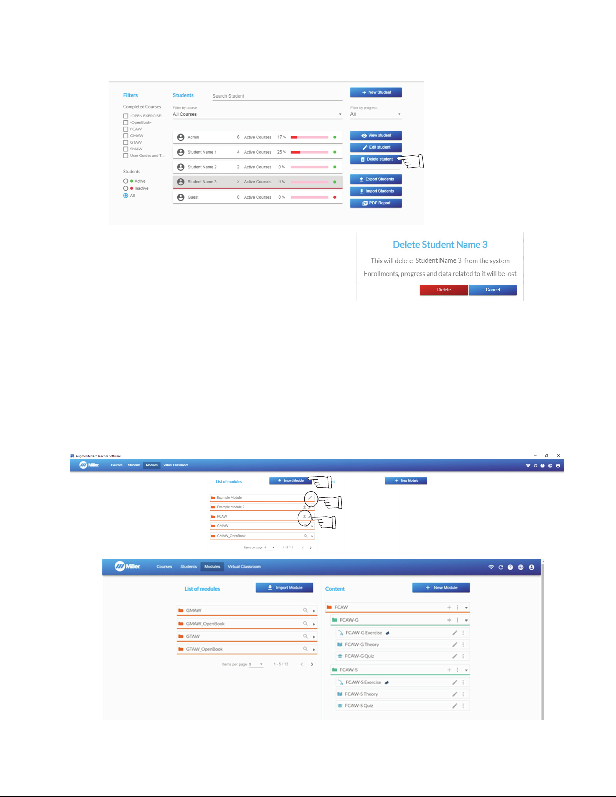
D. Deleting A Student
.
Figure 9-13. Student Data Screen
Select the student to be deleted and click Delete Student. A confirmation window will be displayed. To permanently delete the student and all
data related to the student, click Delete.
Figure 9-14. Delete Student Screen
9-4. Module Management
The left side of the screen displays existing modules. Except for predefined modules, modules can be added to, edited, deleted, exported, and
imported. To edit a module, select the Edit icon. The module content will be displayed on the right side of the screen.
To export a module, select the Export Module icon.
To import a module, select the Import Module icon.
The Teacher Software must be connected to the server to use the import and export functions
F
Predefined modules can be viewed but not edited.
F
OM-278680 Page 66
Figure 9-15. Module Screen
Page 71
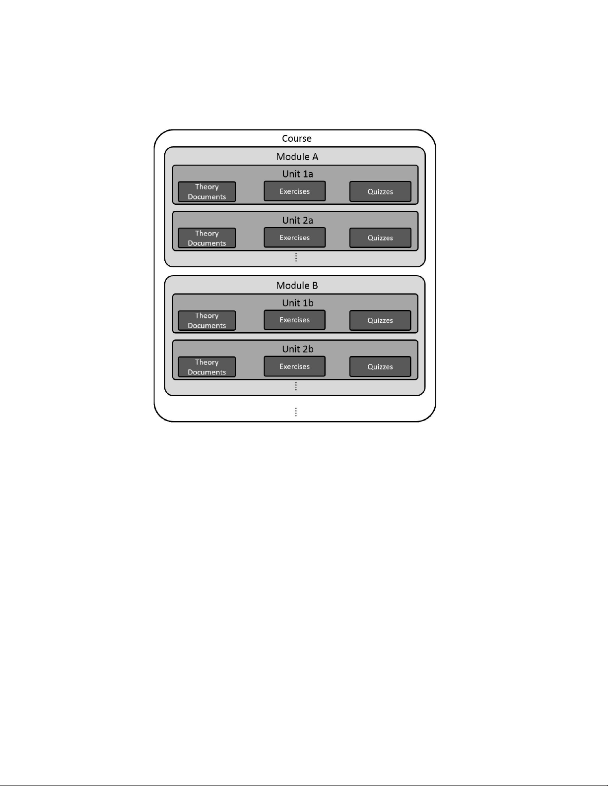
A. Task Information
The task screen displays all the instructional units and exercises included in a particular module. The relationship between courses, modules,
and units is displayed in Figure 9-16.
l A course is composed of one or more modules.
l Each module is composed of the required units.
l The tasks (theory, exercises, and quizzes) are included in the units.
Figure 9-16. Course Structure
OM-278680 Page 67
Page 72
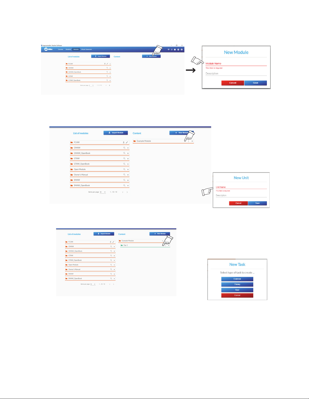
B. Adding A Module
.
Figure 9-8. Module Screen
Click + New Module to add a new module. Enter the module name and description (optional) and click Done. The new module will then be displayed on the right side. Click + within the module to add a unit to the module. Enter the module name and description (optional) and click Done.
Click the + within the unit to add a task to the unit. Click the desired type of task: exercise, theory, or quiz.
Figure 9-17. Adding A Module Screen
Figure 9-18. Adding A Unit Screen
Figure 9-19. Adding A Task Screen
Theory
To add a new Theory, select Theory in the task field. Enter the theory name and description (optional). Click the Theory File box and browse to
the file on the PC. Only PDF files can be uploaded. Click Save to save the theory task.
Maximum file size is 20 Mb.
F
The theory file cannot be viewed in the Teacher Software.
F
OM-278680 Page 68
Page 73
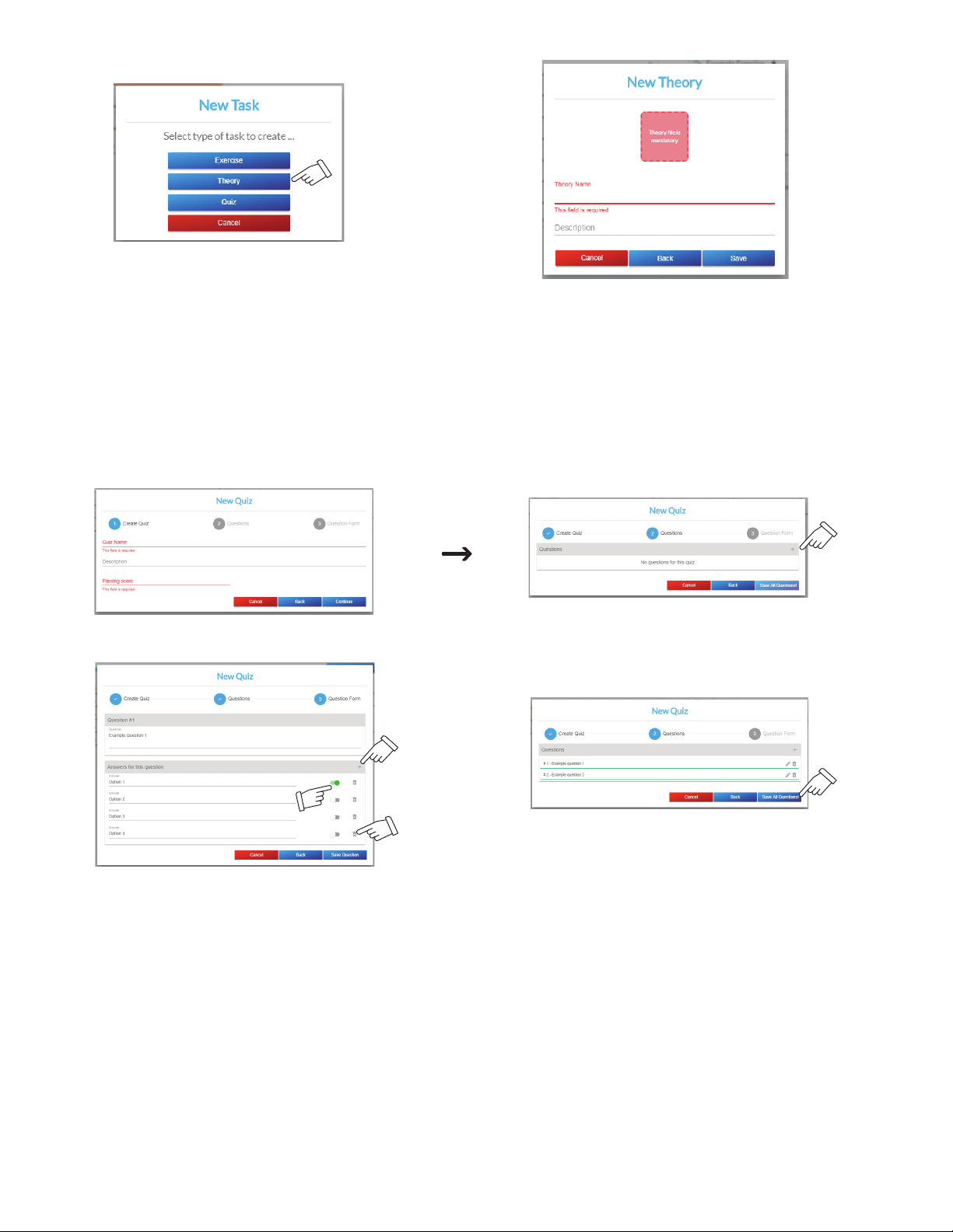
Figure 9-20. Adding A Theory Screen
.
Figure 9-10. Adding A Unit Screen
Quiz
Enter the quiz name, description (optional), and passing score (Figure 9-21). Click Continue. Click + to add a new question to the quiz. Enter
the question. Enter an answer option. Click + to add additional answer options (maximum of six). Click the toggle slider to indicate at least one
correct answer.
Indicating multiple correct answers will require the student to select all correct answers to get the question correct.
F
Click Save Question. Continue adding additional questions to the quiz as desired (a maximum of 20 questions may be added). When completed, select Save All Questions to save the quiz.
Figure 9-21. Adding A Quiz Screen
OM-278680 Page 69
Page 74
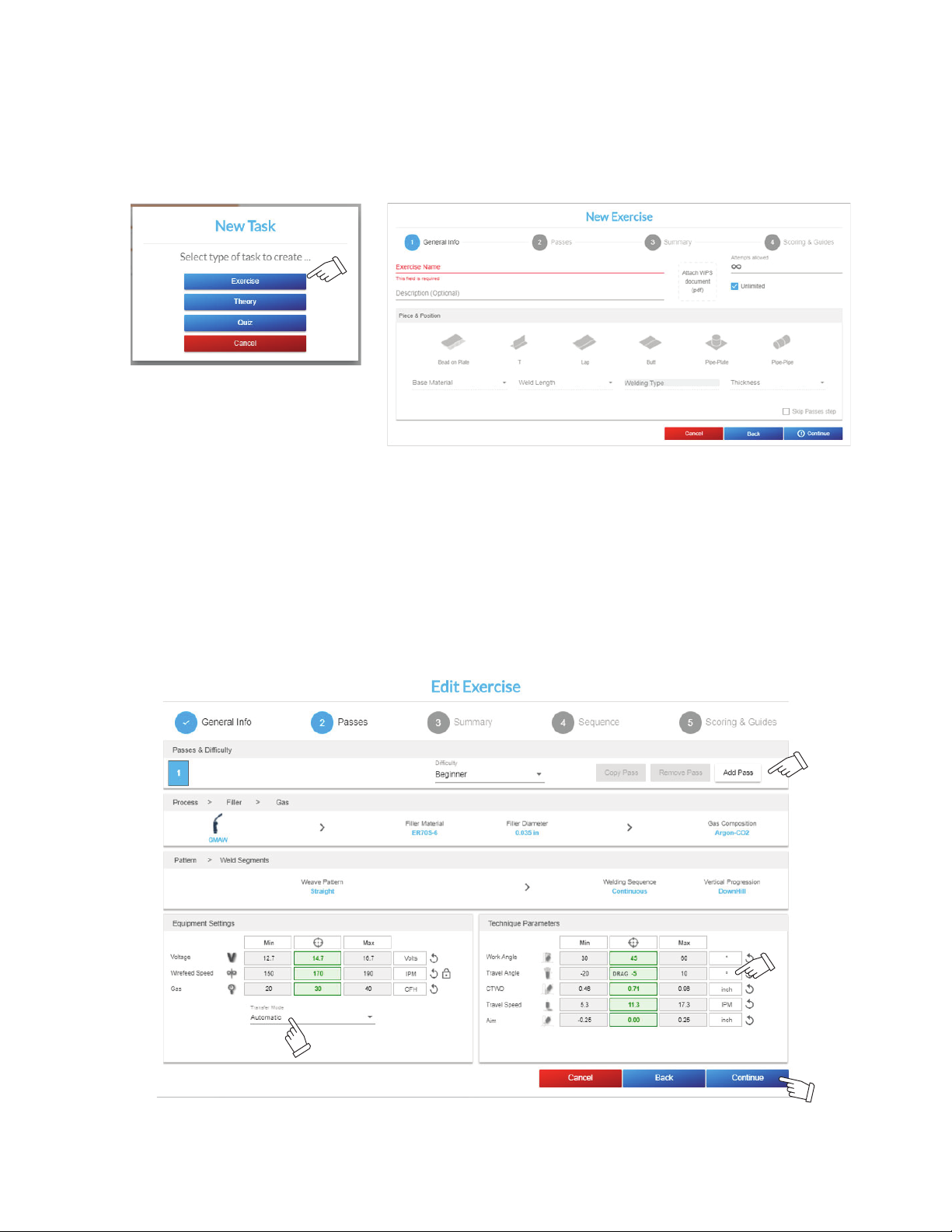
C. Designing The Welding Exercise
.
Figure 9-20. Adding A Theory Screen
Add answer option.
Delete answer option.
Indicate correct answer
.
Figure 9-21. Adding A Quiz Screen
To add a new welding exercise, select Exercise in the task field. The New Exercise General Info screen displays.
Enter the exercise name and description (optional). Attach a WPS .pdf document (optional), which will be viewed by the student in the simulator
before starting the welding exercise. Indicate the number of times the welding exercise can be attempted (the default is unlimited). Select the
joint type, position, base material, weld length, and material thickness. Leaving any of these parameters as undefined (open) will allow the student to select their own option. However, all of these parameters must be defined in order to define any pass details (see next section). Click
Continue to continue defining the exercise.
Figure 9-22. Add Exercise Screen
Select the difficulty level, welding process, filler type/diameter, gas type, weave pattern, and welding sequence. Customize the min, target, or
max values of the equipment settings or technique parameters as desired. Click Add Pass to add a pass and then change any pass details of
the new pass as desired. When all required fields are entered, click Continue.
Under Equipment Settings, override the default transfer mode with the Transfer Mode drop-down menu.
F
You can click the parameter icon to view a detailed definition of the parameter.
F
For travel angle, use negative values for drag and positive values for push.
F
Figure 9-23. Exercise Parameter Selection Screen
Review the summary (Figure 9-24) to confirm the parameters are set correctly; click Back to edit parameters as needed. Click Continue.
OM-278680 Page 70
Page 75
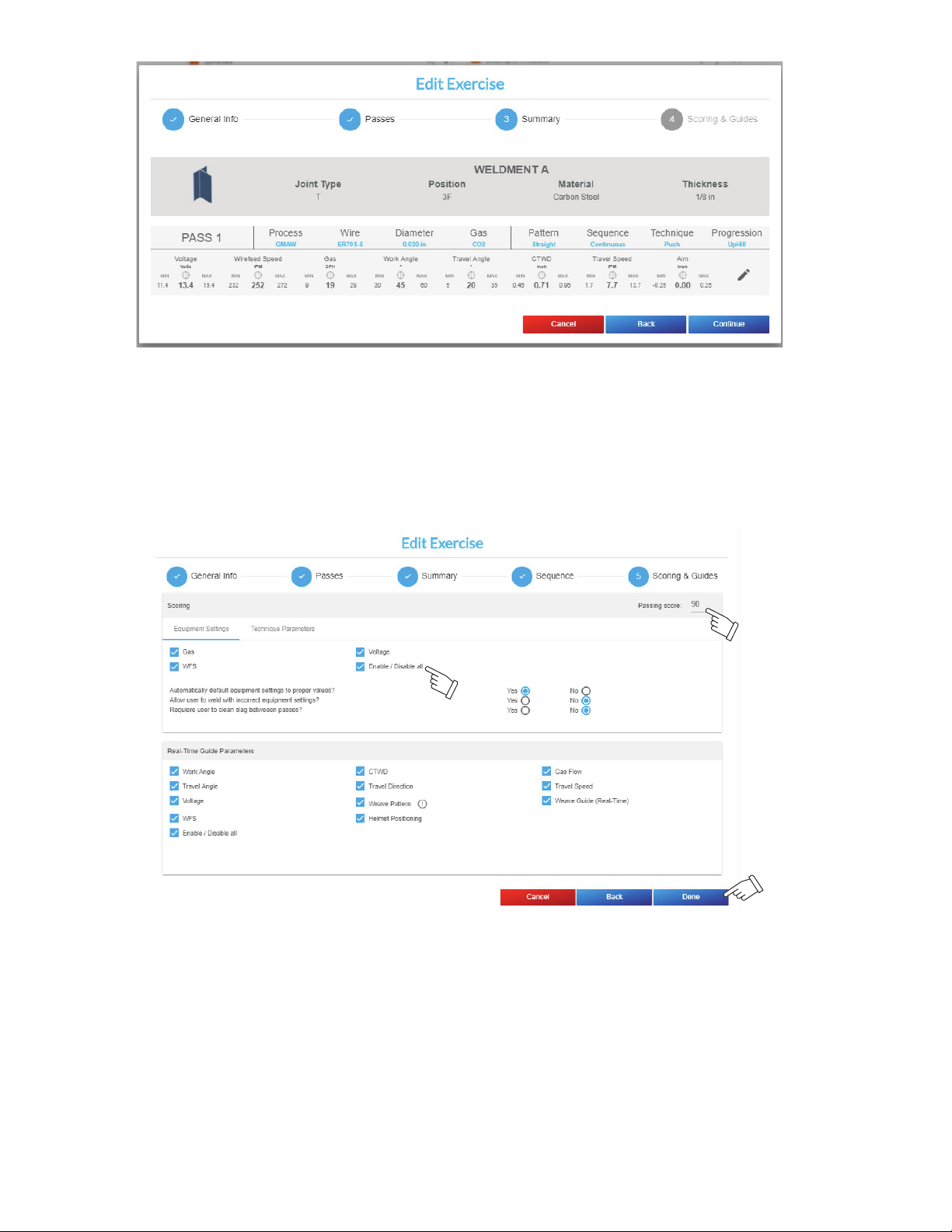
You can click on the parameter icon to
view a detailed definition of the parameter.
For travel angle, use
negative values for a
drag and positive
values for a push.
Override the default
transfer mode with this
drop-down menu.
.
Figure 9-23. Exercise Parameter Selection Screen
Figure 9-24. Exercise Parameter Summary Screen
.
Figure 9-12. Exercise Parameter Selection Screen
The Scoring & Guides screen allows you to select the parameters you want the system to evaluate for the exercise, and also the real-time guide
parameters you want the system to display during the exercise. You can select or deselect all the parameters by clicking the Enable/Disable All
option.
When all parameters have been configured, click Done.
You can also set the passing score, whether the equipment settings are automatically set to proper values, whether the student can contin-
F
ue with incorrect equipment settings, and whether users are required to clean slag between passes for FCAW and SMAW exercises.
Figure 9-25. Exercise Scoring And Guides Equipment Settings Screen
OM-278680 Page 71
Page 76

D. Scoring
The AugmentedArc system provides three difficulty levels: beginner, intermediate, and advanced. The parameter tolerances for each level are
as follows:
Beginner Intermediate Advanced
V (volts) ±2 ±1.5 ±1
A (amps) ±20 ±15 ±10
WFS (inches/min) ±20 ±15 ±10
Gas (cubic feet/hour) ±10 ±7 ±5
Work Angle (deg) ±15 ±10 ±5
Travel Angle (deg) ±15 ±10 ±5
CTWD (inches) ±0.25 ±0.175 ±0.10
Arc Length (inches) ±0.20 ±0.15 ±0.10
Travel Speed (inches/min) ±6 ±4 ±2
Aim (inches) ±0.25 ±0.20 ±0.15
Rod Work Angle (deg) ±20 ±15 ±10
Rod Travel Angle (deg) ±25 ±20 ±15
By default, all Real-Time Guides are enabled. The Real-Time Guides can be individually configured when developing a customer exercise using
the Teacher Software.
OM-278680 Page 72
Page 77
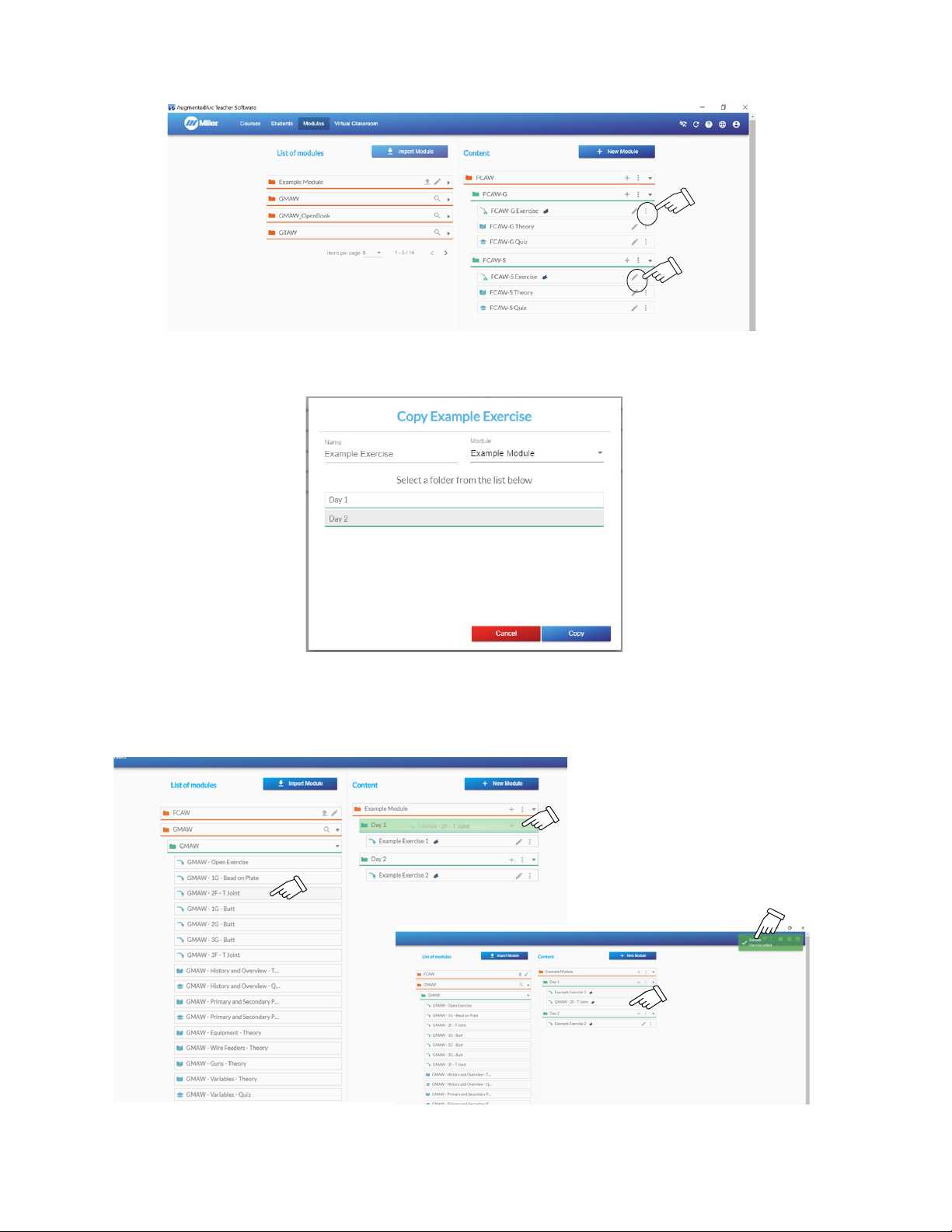
E. Copy Module
Copy or delete
Edit
.
Figure 9-26. Modules Management Screen
To access options to copy or delete a module, unit, or task, click the ⋮symbol. To edit a task, click the Edit icon.
Figure 9-26. Modules Management Screen
After selecting the option to copy a task, enter the name and select the module and unit to copy the task to. Click Copy to create the copy.
Figure 9-27. Copy Screen
Tasks can also be copied from one module to another using drag and drop. Find the module containing the existing task in the list of modules on
the left side. Click the expand icon to view the content of the module. Drag the task to the unit where you want to copy the task and drop it. You
will see the task added within the unit and also a confirmation message. You can also use drag and drop to adjust the order of tasks within a unit,
move tasks from one unit to another within a module, and adjust the order of units within a module.
Figure 9-28. Copying To A Module
OM-278680 Page 73
Page 78
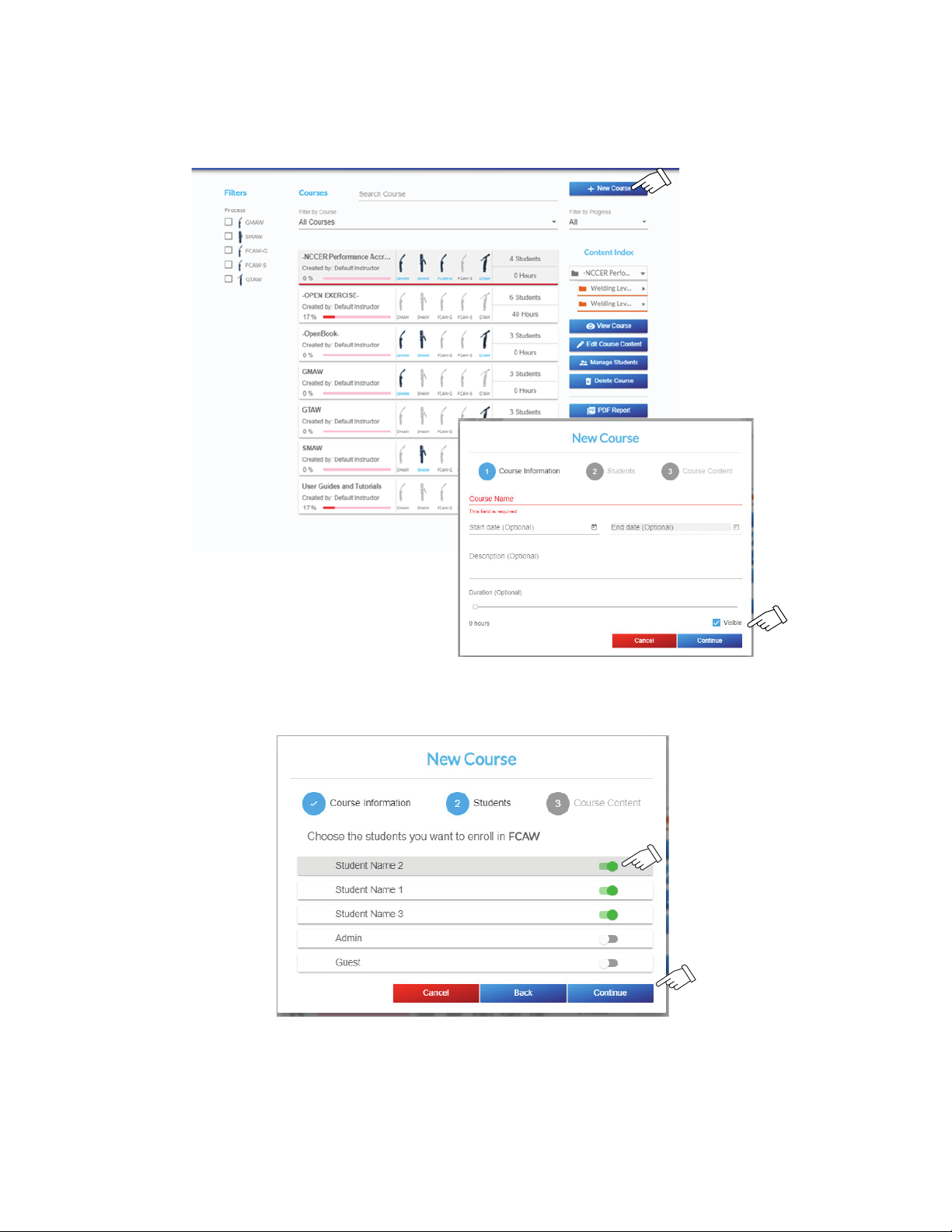
9-5. Course Management
A. Adding Courses
Click + New Course. The New Course screen is displayed. You must enter data in the Course Name field. The remaining fields are optional. If
the Course Visible option is enabled, the selected course will appear in the simulator to students that are enrolled in it. After completing the data
fields, click Continue.
Figure 9-29. Adding A Course
The list of available students is displayed. For each student you want to add to the course, select the toggle button. After all desired students are
added, click Continue.
Figure 9-30. Adding Students To A Course
To add modules to the course, click Edit Content. A list of available modules will be displayed on the left side of the screen. To add a module to
the course, click the + icon or drag and drop the module into the course. If multiple modules are added to the course, use drag and drop to
change the order of the modules within the course.
OM-278680 Page 74
Page 79
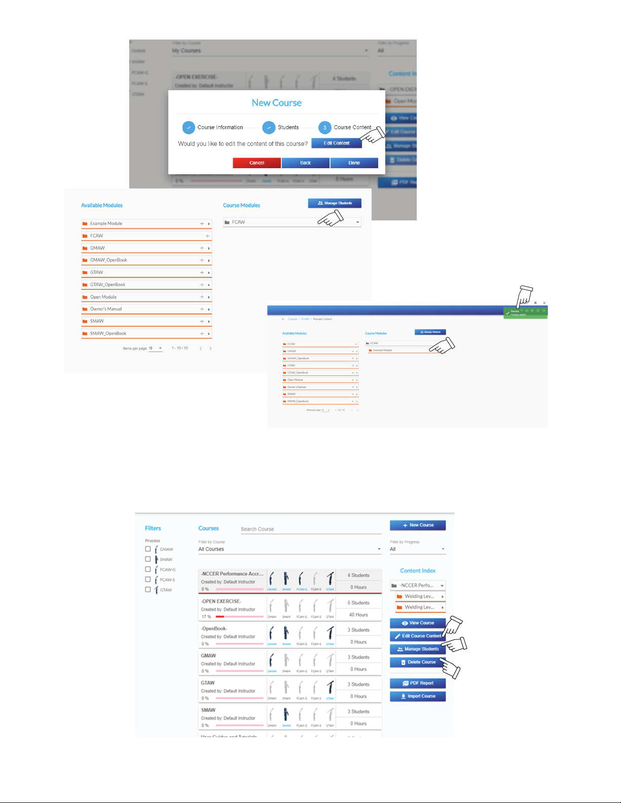
Figure 9-31. Adding A Module To A Course
B. Editing A Course
To edit a course, select the course. Click the Edit Course Content button to edit the list of modules within the course. Click the Manage Students button to edit the list of students enrolled in the course. Click the Delete Course button to permanently delete a course and all associated
data. (Default courses cannot be deleted.)
Figure 9-32. Editing A Course
OM-278680 Page 75
Page 80
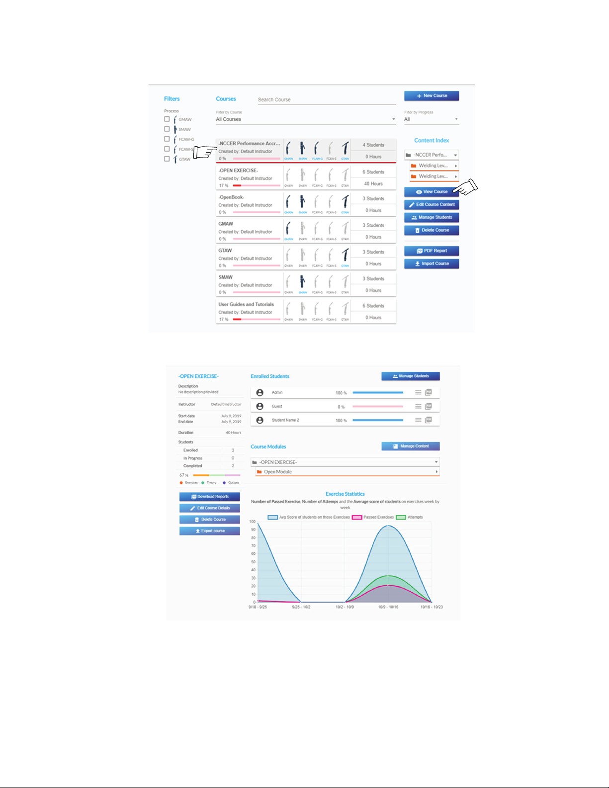
C. Course History
To view course history, select the course. Click View Course. The course overview screen is displayed (Figure 9-33). This shows the completion
progress for each student assigned to the course, a list of all the modules included within the course, and statistics related to student performance in the course.
Figure 9-33. Courses Screen
OM-278680 Page 76
Figure 9-34. Course Overview Screen
Page 81
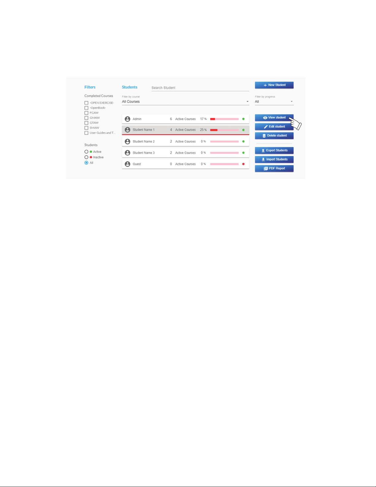
9-6. Reviewing Student Activity And Results
.
Figure 9-34. Course Overview Screen
A. Student Information
To view student progress, select the student. Click View Student. The student overview screen is displayed. This shows the completion progress for each enrolled course and statistics related to student performance in the enrolled courses. Click the Records icon to view the list of test
records for each task within the course. This screen allows the teacher to determine which tasks the student has completed (and not completed),
and how many tasks remain for the student to complete the course. The icons üü(pass) and X (fail) indicate the status of completed activities.
Figure 9-35. Students Screen
OM-278680 Page 77
Page 82
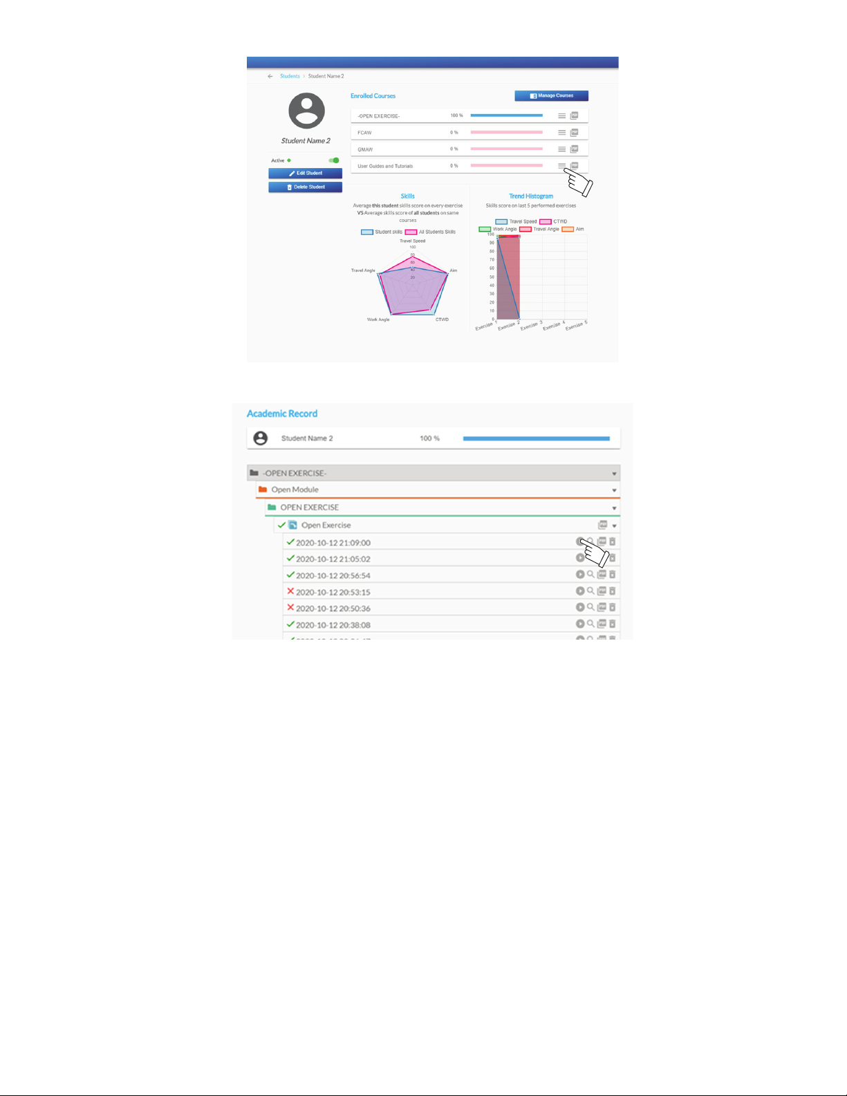
Figure 9-36. Student Course History Screen
Click the Play icon to view the analysis module for an exercise attempt. This displays the detailed test results including the graphs and scores.
Options exist to show the 3D view, view a replay of the simulation, view the WPS for the exercise, and capture a screenshot to be included in the
exercise report.
OM-278680 Page 78
Page 83
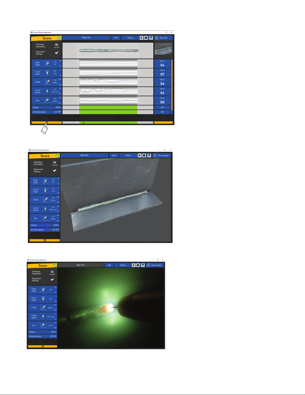
Capture Screenshot
3D View
Replay
Figure 9-37. Reviewing Recent Activity
OM-278680 Page 79
Page 84
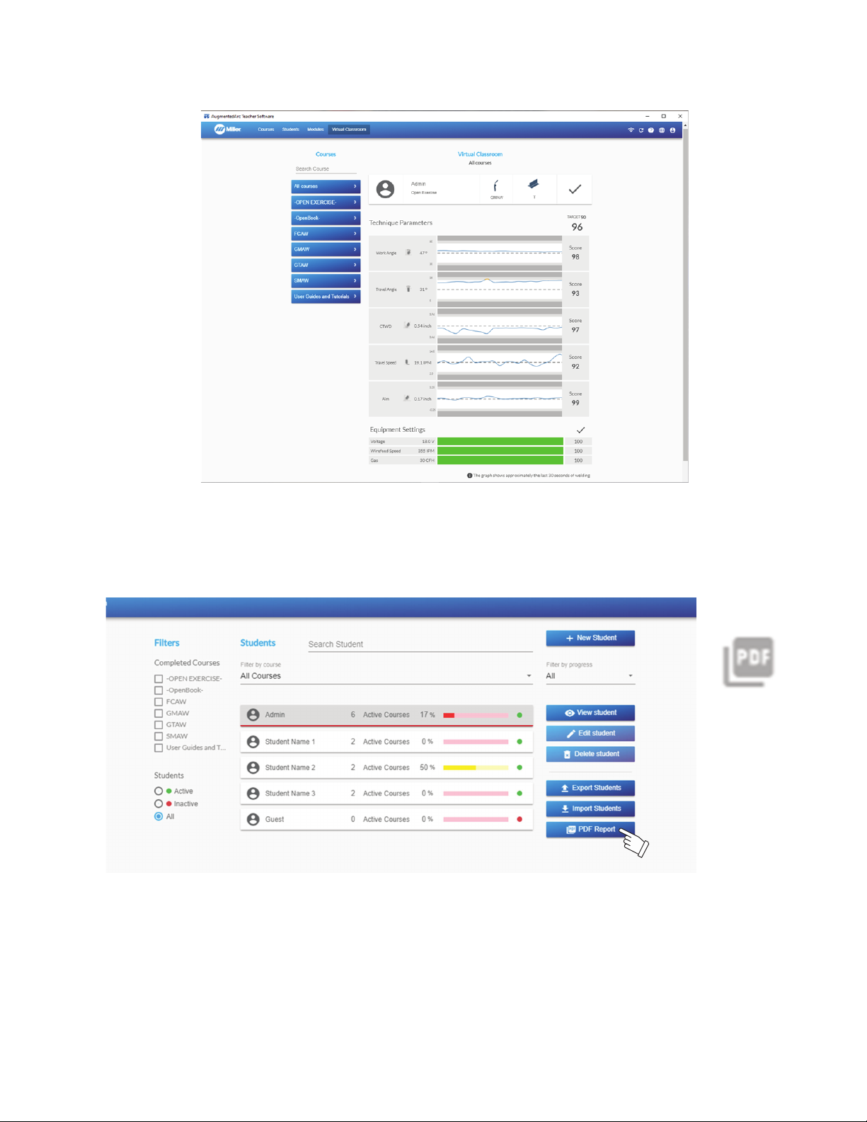
B. Virtual Classroom
.
Figure 9-38. Virtual Classroom
This screen allows the teacher to monitor real-time activity on the simulator. Select the student from the list of online students. The graphs and
scores will update in real-time to reflect the student’s current activity.
Figure 9-38. Virtual Classroom
C. Creating Reports
The Teacher Software can generate PDF reports of various types of information (student progress, list of students, list of courses). Many of the
screens have this option available. Click on the PDF icon or the PDF Report button to generate the desired report.
Figure 9-39. Creating Reports
OM-278680 Page 80
Page 85
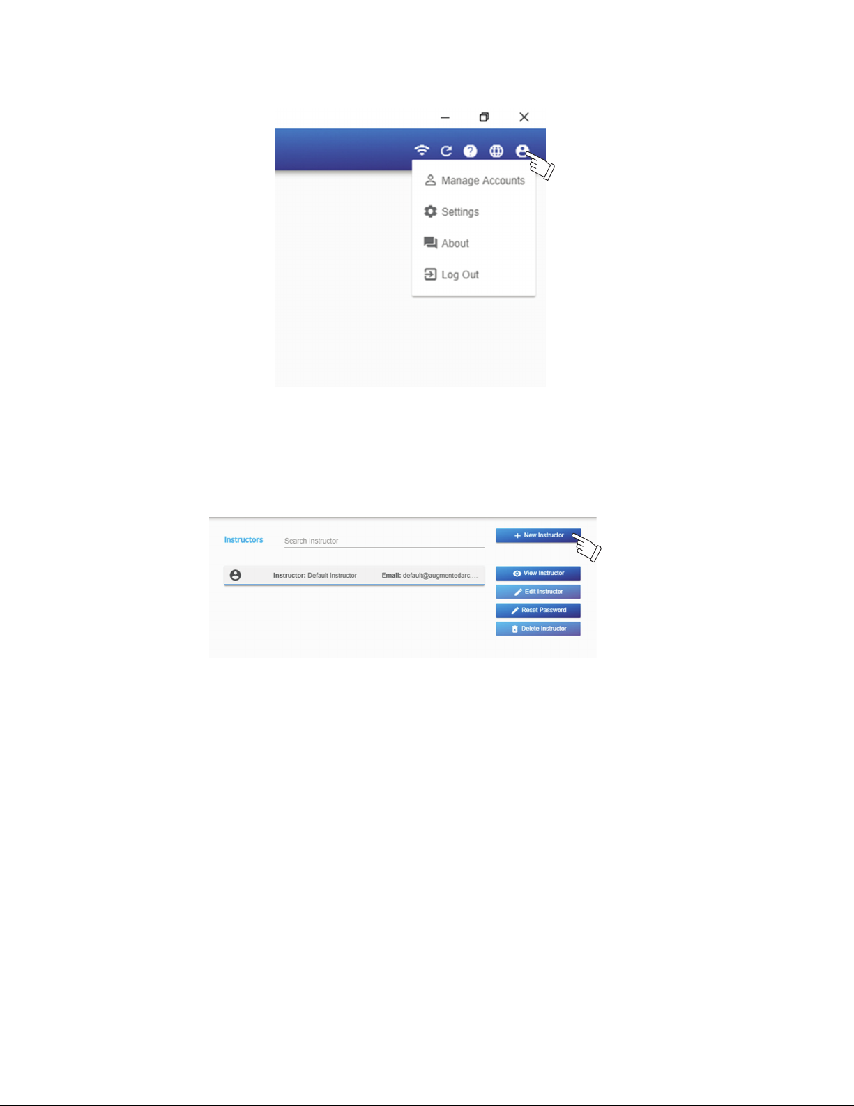
9-7. Account And Settings
.
Figure 9-40. Manage Accounts
Click the Account and Settings icon to access options related to Teacher Software user accounts and settings.
Figure 9-40. Manage Accounts
A. Manage Accounts
Select + New Instructor to add a new instructor account to the Teacher Software. The created courses are associated with the instructor who
creates them. This allows each instructor to easily find and manage their own courses. Options also exist to edit an instructor account profile, reset an instructor account password, and delete an instructor account.
Figure 9-41. Add Instructor
OM-278680 Page 81
Page 86
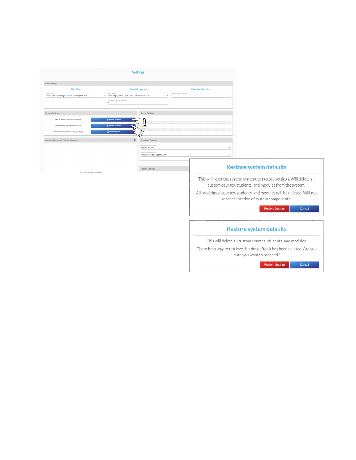
B. Settings
The Settings screen displays information and settings related to charts, system, server, and standards.
The complete data from a system can be backed up by selecting Export Database to save the database file to your PC. That backup can be restored at a later date by selecting Import Database and browsing to the appropriate backup database file.
Click Restore System to restore the system content to the original factory configuration. When confirmation messages appear (two times), select Restore System Defaults to proceed.
OM-278680 Page 82
Figure 9-42. Database Options
Page 87
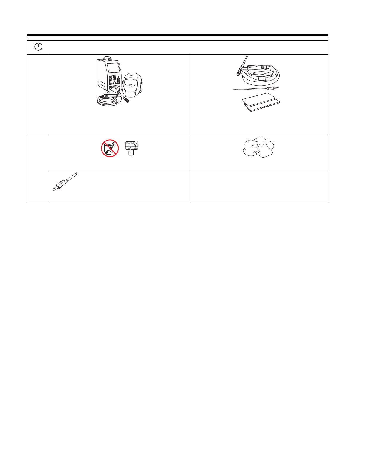
SECTION 10 – ROUTINE MAINTENANCE AND STORAGE
NGO’s
tools/
flathead philips head wrench
knife
heavy-duty workclamp light-duty workclamp wirecutter frontcutter
allen_set
steelbrush nutdriver
chippi
nghammer
imp
d
rill
greasegun
handream
f
ilterwrench
crescent wrench
ü = Check ◇ = Change m = Clean ¶ = Replace
Daily
m Simulator And Helmet Screens With Clean, Damp Cloth.
NOTICE – Do not use chemicals, solvents, or abrasive cleaning
solutions to clean touchscreen or lens covers.
Every 3
Months
¶ Damaged Or Unreadable Labels m Outer Surfaces
m Welding Gun, Torch, Electrode Holder, Filler Rod.
NOTICE – Do not use chemicals, solvents, or abrasive cleaning
solutions to clean touchscreen or lens covers.
m Fans on rear and power supply
NOTICE – Do not use solvents or abrasive cleaning detergents to clean the AugmentedArc components. Do not immerse any of the components
in water.
NOTICE – Keep the components dry; do not expose the components to rain or snow. Keep components away from fire and other sources of
heat.
NOTICE – The AugmentedArc system uses sensitive electronics. Do not drop or handle components in a rough manner.
The AugmentedArc system requires little maintenance. However, for best performance, use a soft cloth dampened with a mild soap and water to
clean outer surfaces of components after each use. Allow to air dry. Occasionally, the lens covers and display screen should be cleaned by gently wiping with a soft, dry cloth.
Store the AugmentedArc system in a clean, dry, cool place free of solvent-based vapors. Use Miller transportation case 951775 to store or transport the equipment.
End Of Useful Life
The AugmentedArc has no expiration date, and with proper care and maintenance it can provide many years of simulated welding training.
OM-278680 Page 83
Page 88
SECTION 11 – TROUBLESHOOTING TABLE
Always be certain software is updated to the current version.
F
For Classroom mode systems, be sure both the simulator and controller are updated to the current version of software.
F
The AugmentedArc system will reboot after eight hours of inactivity.
F
At the start of a new simulation exercise, if the system detects low memory the software will restart and automatically return to the in-
F
tended simulation.
Trouble Remedy
Simulator does not turn on. Place simulator Input Power switch in On position. Place simulator Power On-Off switch in the On
Augmented Reality system does not
operate.
System does not track gun/electrode. Be sure hands, tools, or debris are not blocking markers on gun or electrode
Unable to connect to AugmentedArc
system when using teacher software.
External monitor(s) displays initial
start-up screens but not subsequent
screens.
position (see Sections 5-3 and 6-1).
Check input power connections at AC receptacle and simulator (see Section 5-1).
Reset circuit breaker on power strip (if used). See Section 5-1.
Have Factory Authorized Service Agent check simulator.
Remove dirt and debris from helmet screen.
Adjust helmet lighting and check position of helmet and gun/electrode and workpiece.
Have Factory Authorized Service Agent check simulator and gun/electrode.
Adjust brightness of helmet LEDs.
Perform a lighting calibration. See Section 7-2.
Clean camera lens cover.
Recalibrate helmet cameras. See Section 8-6.
Check for correct IP address. For Standalone mode, check the IP address on the AugmentedArc
(see 9-5) and reenter it. For Classroom mode, enter 10.0.0.1.
Failure to connect to the AugmentedArc Network. Verify the router and simulator are properly connected. Verify your PC is connected to the proper network (see Section 9-3).
The version of the Teacher Software does not match the version installed on the simulator. Download
the latest software from the website (see Section 9-1) and update the simulator software and Teacher Software.
If external router is not used, be sure WiFi Access Point is enabled (see section 8-2).
After simulator starts up, disconnect HDMI cable from the simulator and then reconnect it.
OM-278680 Page 84
Page 89
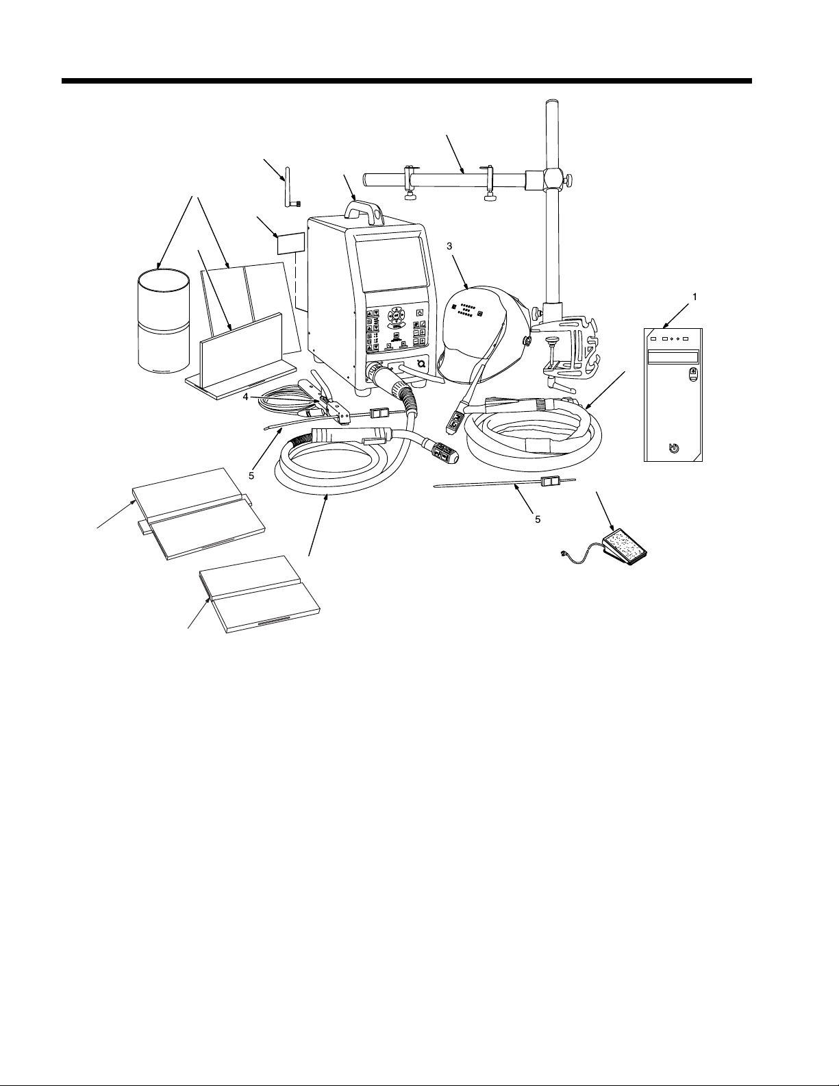
SECTION 12 – PARTS LIST
10
11
12
13
14
15
16
6
7
8
9
Figure 12-1. AugmentedArc Components
OM-278680 Page 85
Page 90

12-1. AugmentedArc Components
Item No. Part No. Description Quantity
1 ♦301395 Controller 1
278181 —Router, Classroom 1
2 ♦277196 Heavy Duty Transportation Case - Accessories (Not Shown) 1
2 ♦277197 Heavy Duty Transportation Case - Simulator (Not Shown) 1
3 AR Helmet Assembly 1
*276240 Cover, LED AR Helmet 1
*284218 Headgear, Gray 1
256178 —Kit, Adjustment Angle/Stop Hardware (Hardware Kit With O-Rings) 1
770249 —Headband, Cosmel Fabric 1
271326 —Cushion, Top Headgear 1
271335 Shell, Helmet Black Infinity 1
*286018 Holder, Magnetic Lens 1
♦212242 Magnifying Lens, Diopter 2.50 1
♦212240 Magnifying Lens, Diopter 2.00 1
♦212238 Magnifying Lens, Diopter 1.50 1
4 277258 SMAW Stinger Only 1
5 277267 SMAW Electrode/TIG Filler Rod With AR Marker Assembly 2
6 301400 TIG Torch (Does Not Include AR Tip) 1
283068 TIG Torch Nozzle Assembly 1
277272 TIG Torch AR Tip 1
7 301401 MIG Gun (Does Not Include AR Tip) 1
277269 MIG Gun AR Nozzle Assembly 1
8 277274 Butt/Pipe/Pipe to Pipe/Pipe to Plate Joint (Workpieces C, D, and E) 1
9 277270 T-Joint/Lap Joint (Workpieces A and B) 1
10 290648 Coupon NCCER, V-Groove W/ Backing 1
11 290649 Coupon NCCER, V-Groove W/O Backing 1
12 286000 Label, Warning General Precautionary 1
13 286055 Simulator Assembly 1
265650 —Handle Assembly, Center 1
14 277277 WiFi Antenna 2
15 277266 Workpiece Stand 1
16 ♦286033 TIG Foot Pedal Kit (Optional) 1
Hardware is common and not available unless listed.
F
*Recommended Spare Parts
♦Optional
+When ordering a component originally displaying a precautionary label, the label should also be ordered. Labels available separately or as part
of label kit.
To maintain the factory original performance of your equipment, use only Manufacturer’s Suggested Replacement Parts. Model and
serial number required when ordering parts from your local distributor.
OM-278680 Page 86
Page 91

Effective January 1, 2023 (Equipment with a serial number preface of ND or newer)
This limited warranty supersedes all previous Miller warranties and is exclusive with no other guarantees or war-
ranties expressed or implied.
LIMITED WARRANTY - Subject to the terms and
conditions below, Miller Electric Mfg. LLC, Appleton, Wisconsin, warrants to authorized distributors
that new Miller equipment sold after the effective
date of this limited warranty is free of defects in
material and workmanship at the time it is shipped
by Miller. THIS WARRANTY IS EXPRESSLY IN
LIEU OF ALL OTHER WARRANTIES, EXPRESS
OR IMPLIED, INCLUDING THE WARRANTIES
OF MERCHANTABILITY AND FITNESS.
Within the warranty periods listed below, Miller will
repair or replace any warranted parts or components that fail due to such defects in material or
workmanship. Miller must be notified in writing
within thirty (30) days of such defect or failure, at
which time Miller will provide instructions on the
warranty claim procedures to be followed. Notifications submitted as online warranty claims must
provide detailed descriptions of the fault and troubleshooting steps taken to diagnose failed parts.
Warranty claims that lack the required information
as defined in the Miller Service Operation Guide
(SOG) may be denied by Miller.
Miller shall honor warranty claims on warranted
equipment listed below in the event of a defect
within the warranty coverage time periods listed
below. Warranty time periods start on the delivery
date of the equipment to the end-user purchaser,
or 12 months after the equipment is shipped to a
US or Canada distributor, or 18 months after the
equipment is shipped to an international distributor,
whichever occurs first.
1 5 Years Parts — 3 Years Labor
l Original Main Power Rectifiers Only to Include
SCRs, Diodes, and Discrete Rectifier Modules
in non-inverter products
2 4 Years Parts (No Labor)
l Auto-Darkening ClearLight 2.0 Helmet Lenses
3 3 Years — Parts and Labor Unless Specified
l Auto-Darkening Helmet Lenses (No Labor)
l Engine Driven Welder/Generators (Including
EnPak) (NOTE: Engines are Warranted
Separately by the Engine Manufacturer.)
l Insight Welding Intelligence Products (Except
External Sensors)
l Inverter Power Sources
l Plasma Arc Cutting Power Sources
l Process Controllers
l Semi-Automatic and Automatic Wire Feeders
l Transformer/Rectifier Power Sources
4 2 Years — Parts and Labor
l Auto-Darkening Weld Masks (No Labor)
l Fume Extractors - Filtair 215, Capture 5, and
Industrial Collector Series
5 1 Year — Parts and Labor Unless Specified
l ArcReach Heater
l AugmentedArc, LiveArc, and MobileArc Weld-
ing Systems
l Automatic Motion Devices
l Bernard BTB Air-Cooled MIG Guns (No
Labor)
l CoolBelt, PAPR Blower, and PAPR Face
Shield (No Labor)
l Desiccant Air Dryer System
l Field Options (NOTE: Field options are cov-
ered for the remaining warranty period of
the product they are installed in, or for a
minimum of one year — whichever is
greater.)
l RFCS Foot Controls (Except RFCS-RJ45)
l Fume Extractors - Filtair 130, MWX and SWX
Series, ZoneFlow Extraction Arms and Motor
Control Box
l HF Units
l ICE/XT Plasma Cutting Torches (No Labor)
l Induction Heating Power Sources, Coolers
(NOTE: Digital Recorders are Warranted
Separately by the Manufacturer.)
l Insight Sensors
l Load Banks
l Motor-Driven Guns (except Spoolmate
Spoolguns)
l Positioners and Controllers
l Racks (For Housing Multiple Power Sources)
l Running Gear/Trailers
l Subarc Wire Drive Assemblies
l Supplied Air Respirator (SAR) Boxes and
Panels
l TIG Torches (No Labor)
l Tregaskiss Guns (No Labor)
l Water Cooling Systems
l Wireless Remote Foot/Hand Controls and
Receivers
l Work Stations/Weld Tables (No Labor)
6 6 Months — Parts
l 12 Volt Automotive-Style Batteries
7 90 Days — Parts
l Accessories (Kits)
l ArcReach Heater Quick Wrap and Air Cooled
Cables
l Canvas Covers
l Induction Heating Coils and Blankets, Cables,
and Non-Electronic Controls
l MDX Series MIG Guns
l M-Guns
l MIG Guns, Subarc (SAW) Torches, and Exter-
nal Cladding Heads
l Remote Controls and RFCS-RJ45
l Replacement Parts (No labor)
l Spoolmate Spoolguns
Miller’s True Blue
to:
1. Consumable components; such as contact
tips, cutting nozzles, contactors, brushes,
relays, work station table tops and welding
curtains, or parts that fail due to normal
wear. (Exception: brushes and relays are
covered on all engine-driven products.)
2. Items furnished by Miller, but manufactured by
others, such as engines or trade accessories.
These items are covered by the manufacturer ’s
warranty, if any.
3. Equipment that has been modified by any party
other than Miller, or equipment that has been
®
Limited Warranty shall not apply
improperly installed, improperly operated or
misused based upon industry standards, or
equipment which has not had reasonable and
necessary maintenance, or equipment which
has been used for operation outside of the
specifications for the equipment.
4. Defects caused by accident, unauthorized repair, or improper testing.
MILLER PRODUCTS ARE INTENDED FOR
COMMERCIAL AND INDUSTRIAL USERS
TRAINED AND EXPERIENCED IN THE USE AND
MAINTENANCE OF WELDING EQUIPMENT.
The exclusive remedies for warranty claims are, at
Miller’s option, either: (1) repair; or (2) replacement; or, if approved in writing by Miller, (3) the
pre-approved cost of repair or replacement at an
authorized Miller service station; or (4) payment of
or credit for the purchase price (less reasonable
depreciation based upon use). Products may not
be returned without Miller’s written approval. Return shipment shall be at customer’s risk and
expense.
The above remedies are F.O. B. Appleton, WI, or
Miller’s authorized service facility. Transportation
and freight are the customer’s responsibility. TO
THE EXTENT PERMITTED BY LAW, THE REMEDIES HEREIN ARE THE SOLE AND EXCLUSIVE REMEDIES REGARDLESS OF THE LEGAL
THEORY. IN NO EVENT SHALL MILLER BE LIABLE FOR DIRECT, INDIRECT, SPECIAL, INCIDENTAL OR CONSEQUENTIAL DAMAGES
(INCLUDING LOSS OF PROFIT) REGARDLESS
OF THE LEGAL THEORY. ANY WARRANTY NOT
PROVIDED HEREIN AND ANY IMPLIED WARRANTY, GUARANTY, OR REPRESENTATION, INCLUDING ANY IMPLIED WARRANTY OF
MERCHANTABILITY OR FITNESS FOR PARTICULAR PURPOSE, ARE EXCLUDED AND DISCLAIMED BY MILLER.
Some US states do not allow limiting the duration
of an implied warranty or the exclusion of certain
damages, so the above limitations may not apply
to you. This warranty provides specific legal rights,
and other rights may be available depending on
your state. In Canada, some provinces provide additional warranties or remedies, and to the extent
the law prohibits their waiver, the limitations set out
above may not apply. This Limited Warranty provides specific legal rights, and other rights may be
available, but may vary by province.
Warranty Questions?
Call 1-800-4-A-MILLER for
your local Miller distributor.
Your distributor also gives you...
Service
You always get the fast, reliable response you
need. Most replacement parts can be in your
hands in 24 hours.
Support
Need fast answers to the tough welding questions? The expertise of the distributor and Miller
is there to help you, every step of the way.
Page 92
Owner’s Record
Please complete and retain with your personal records.
Model Name Serial/Style Number
Purchase Date
Distributor
Address
City
State Zip
(Date which equipment was delivered to original customer.)
For Service
Contact a DISTRIBUTOR or SERVICE AGENCY near you.
Always provide Model Name and Serial/Style Number.
Contact your Distributor for:
Welding Supplies and Consumables
Options and Accessories
Personal Protective Equipment (PPE)
Contact the Delivering Carrier to:
Service and Repair Replacement Parts
Training (Schools, Videos, Books)
Welding Process Handbooks
To locate a Distributor or Service Agency visit
www.millerwelds.com or call 1-800-4-A-Miller
File a claim for loss or damage during
shipment.
For assistance in filing or settling claims, contact your distributor and/or equipment manufacturer’s Transportation Department.
Miller Electric Mfg. LLC
An Illinois Tool Works Company
1635 West Spencer Street
Appleton, WI 54914 USA
International Headquarters–USA
USA Phone: 920-735-4505
USA & Canada FAX: 920-735-4134
International FAX: 920-735-4125
For International Locations Visit
www.MillerWelds.com
ORIGINAL INSTRUCTIONS – PRINTED IN USA © Miller Electric Mfg. LLC 2023-03
 Loading...