


OM-157 066V
November 2000
Processes
|
|
|
|
MIG (GMAW) Welding |
|
|
|||
|
|
Flux Cored (FCAW) Welding |
||
|
|
|
|
|
|
|
|
|
Description |
|
|
|
|
|
|
|
|
|
Arc Welding Power Source And |
|
|
|
|
Wire Feeder |
Auto ArcR 255
And M-25 Gun
For Warranty Claims And Technical Support, Contact: Milweld Inc., National Distributor
P.O. Box 338, Hortonville, WI 54944-0338 Tel 920-779-0916 Fax 920-779-0924


 WARNING
This product, when used for welding or cutting, produces fumes or gases which contain chemicals known to the State of California to cause birth defects and, in some cases, cancer. (California Health & Safety Code Section 25249.5 et seq.)
The following terms are used interchangeably throughout this manual:
MIG = GMAW
OM-154 501V
TABLE OF CONTENTS
SECTION 1 – SAFETY PRECAUTIONS - READ BEFORE USING . . . . . . . . . . . . . . . . . . . . . . . . . . . . |
1 |
|
1-1. |
Symbol Usage . . . . . . . . . . . . . . . . . . . . . . . . . . . . . . . . . . . . . . . . . . . . . . . . . . . . . . . . . . . . . . . . |
1 |
1-2. |
Arc Welding Hazards . . . . . . . . . . . . . . . . . . . . . . . . . . . . . . . . . . . . . . . . . . . . . . . . . . . . . . . . . . |
1 |
1-3. Additional Symbols For Installation, Operation, And Maintenance . . . . . . . . . . . . . . . . . . . . . |
3 |
|
1-4. |
Principal Safety Standards . . . . . . . . . . . . . . . . . . . . . . . . . . . . . . . . . . . . . . . . . . . . . . . . . . . . . |
3 |
1-5. |
EMF Information . . . . . . . . . . . . . . . . . . . . . . . . . . . . . . . . . . . . . . . . . . . . . . . . . . . . . . . . . . . . . . |
4 |
SECTION 2 – INSTALLATION . . . . . . . . . . . . . . . . . . . . . . . . . . . . . . . . . . . . . . . . . . . . . . . . . . . . . . . . . . . |
5 |
||
2-1. |
Specifications . . . . . . . . . . . . . . . . . . . . . . . . . . . . . . . . . . . . . . . . . . . . . . . . . . . . . . . . . . . . . . . . |
5 |
|
2-2. |
|
Volt-Ampere Curve . . . . . . . . . . . . . . . . . . . . . . . . . . . . . . . . . . . . . . . . . . . . . . . . . . . . . . . . . . . . |
5 |
2-3. Welding Power Source Duty Cycle And Overheating . . . . . . . . . . . . . . . . . . . . . . . . . . . . . . . . |
6 |
||
2-4. |
Welding Gun Duty Cycle And Overheating . . . . . . . . . . . . . . . . . . . . . . . . . . . . . . . . . . . . . . . . |
6 |
|
2-5. |
Installing Work Clamp . . . . . . . . . . . . . . . . . . . . . . . . . . . . . . . . . . . . . . . . . . . . . . . . . . . . . . . . . . |
7 |
|
2-6. |
|
Installing Gas Supply . . . . . . . . . . . . . . . . . . . . . . . . . . . . . . . . . . . . . . . . . . . . . . . . . . . . . . . . . . |
7 |
2-7. |
Installing Welding Gun . . . . . . . . . . . . . . . . . . . . . . . . . . . . . . . . . . . . . . . . . . . . . . . . . . . . . . . . . |
8 |
|
2-8. |
Installing Wire Spool And Adjusting Hub Tension . . . . . . . . . . . . . . . . . . . . . . . . . . . . . . . . . . . |
8 |
|
2-9. |
|
Setting Gun Polarity . . . . . . . . . . . . . . . . . . . . . . . . . . . . . . . . . . . . . . . . . . . . . . . . . . . . . . . . . . . |
9 |
2-10. Positioning Jumper Links . . . . . . . . . . . . . . . . . . . . . . . . . . . . . . . . . . . . . . . . . . . . . . . . . . . . . . . |
9 |
||
2-11. |
Electrical Service Guide . . . . . . . . . . . . . . . . . . . . . . . . . . . . . . . . . . . . . . . . . . . . . . . . . . . . . . . . |
10 |
|
2-12. |
Selecting A Location And Connecting Input Power . . . . . . . . . . . . . . . . . . . . . . . . . . . . . . . . . . |
10 |
|
2-13. |
Threading Welding Wire . . . . . . . . . . . . . . . . . . . . . . . . . . . . . . . . . . . . . . . . . . . . . . . . . . . . . . . . |
11 |
|
SECTION 3 – OPERATION . . . . . . . . . . . . . . . . . . . . . . . . . . . . . . . . . . . . . . . . . . . . . . . . . . . . . . . . . . . . . |
12 |
|
3-1. |
Front Panel Controls . . . . . . . . . . . . . . . . . . . . . . . . . . . . . . . . . . . . . . . . . . . . . . . . . . . . . . . . . . . |
12 |
3-2. |
Center Baffle Controls . . . . . . . . . . . . . . . . . . . . . . . . . . . . . . . . . . . . . . . . . . . . . . . . . . . . . . . . . |
13 |
3-3. |
Weld Parameter Chart . . . . . . . . . . . . . . . . . . . . . . . . . . . . . . . . . . . . . . . . . . . . . . . . . . . . . . . . . |
14 |
SECTION 4 – MAINTENANCE & TROUBLESHOOTING . . . . . . . . . . . . . . . . . . . . . . . . . . . . . . . . . . . . |
16 |
|
4-1. |
Routine Maintenance . . . . . . . . . . . . . . . . . . . . . . . . . . . . . . . . . . . . . . . . . . . . . . . . . . . . . . . . . . |
16 |
4-2. |
Circuit Breaker CB1 . . . . . . . . . . . . . . . . . . . . . . . . . . . . . . . . . . . . . . . . . . . . . . . . . . . . . . . . . . . |
16 |
4-3. Fuses F1 And F2 . . . . . . . . . . . . . . . . . . . . . . . . . . . . . . . . . . . . . . . . . . . . . . . . . . . . . . . . . . . . . |
17 |
|
4-4. Changing Drive Roll And Wire Inlet Guide . . . . . . . . . . . . . . . . . . . . . . . . . . . . . . . . . . . . . . . . . |
17 |
|
4-5. Replacing Gun Contact Tip . . . . . . . . . . . . . . . . . . . . . . . . . . . . . . . . . . . . . . . . . . . . . . . . . . . . . |
17 |
|
4-6. Cleaning Or Replacing Gun Liner . . . . . . . . . . . . . . . . . . . . . . . . . . . . . . . . . . . . . . . . . . . . . . . . |
18 |
|
4-7. |
Replacing Switch And/Or Head Tube . . . . . . . . . . . . . . . . . . . . . . . . . . . . . . . . . . . . . . . . . . . . . |
19 |
4-8. |
Troubleshooting . . . . . . . . . . . . . . . . . . . . . . . . . . . . . . . . . . . . . . . . . . . . . . . . . . . . . . . . . . . . . . |
20 |
SECTION 5 – ELECTRICAL DIAGRAM . . . . . . . . . . . . . . . . . . . . . . . . . . . . . . . . . . . . . . . . . . . . . . . . . . . |
21 |
|
SECTION 6 – PARTS LIST . . . . . . . . . . . . . . . . . . . . . . . . . . . . . . . . . . . . . . . . . . . . . . . . . . . . . . . . . . . . . . |
23 |
|
OPTIONS AND ACCESSORIES |
|
|
WARRANTY |
|
|
SECTION 1 – SAFETY PRECAUTIONS - READ BEFORE USING
som _nd_4/98
1-1. Symbol Usage
Means Warning! Watch Out! There are possible hazards with this procedure! The possible hazards are shown in the adjoining symbols.
Y Marks a special safety message.
. Means “Note”; not safety related.
This group of symbols means Warning! Watch Out! possible
ELECTRIC SHOCK, MOVING PARTS, and HOT PARTS hazards. Consult symbols and related instructions below for necessary actions to avoid the hazards.
1-2. Arc Welding Hazards
YThe symbols shown below are used throughout this manual to call attention to and identify possible hazards. When you see the symbol, watch out, and follow the related instructions to avoid the hazard. The safety information given below is only a summary of the more complete safety information found in the Safety Standards listed in Section 1-4. Read and follow all Safety Standards.
YOnly qualified persons should install, operate, maintain, and repair this unit.
YDuring operation, keep everybody, especially children, away.
ELECTRIC SHOCK can kill.
Touching live electrical parts can cause fatal shocks or severe burns. The electrode and work circuit is electrically live whenever the output is on. The input power circuit and machine internal circuits are also
live when power is on. In semiautomatic or automatic wire welding, the wire, wire reel, drive roll housing, and all metal parts touching the welding wire are electrically live. Incorrectly installed or improperly grounded equipment is a hazard.
DDo not touch live electrical parts.
DWear dry, hole-free insulating gloves and body protection.
DInsulate yourself from work and ground using dry insulating mats or covers big enough to prevent any physical contact with the work or ground.
DDo not use AC output in damp areas, if movement is confined, or if there is a danger of falling.
DUse AC output ONLY if required for the welding process.
DIf AC output is required, use remote output control if present on unit.
DDisconnect input power or stop engine before installing or servicing this equipment. Lockout/tagout input power according to OSHA 29 CFR 1910.147 (see Safety Standards).
DProperly install and ground this equipment according to its Owner’s Manual and national, state, and local codes.
DAlways verify the supply ground – check and be sure that input power cord ground wire is properly connected to ground terminal in disconnect box or that cord plug is connected to a properly grounded receptacle outlet.
DWhen making input connections, attach proper grounding conductor first – double-check connections.
DFrequently inspect input power cord for damage or bare wiring – replace cord immediately if damaged – bare wiring can kill.
DTurn off all equipment when not in use.
DDo not use worn, damaged, undersized, or poorly spliced cables.
DDo not drape cables over your body.
DIf earth grounding of the workpiece is required, ground it directly with a separate cable.
DDo not touch electrode if you are in contact with the work, ground, or another electrode from a different machine.
DUse only well-maintained equipment. Repair or replace damaged parts at once. Maintain unit according to manual.
DWear a safety harness if working above floor level.
DKeep all panels and covers securely in place.
DClamp work cable with good metal-to-metal contact to workpiece or worktable as near the weld as practical.
DInsulate work clamp when not connected to workpiece to prevent contact with any metal object.
DDo not connect more than one electrode or work cable to any single weld output terminal.
SIGNIFICANT DC VOLTAGE exists after removal of input power on inverters.
DTurn Off inverter, disconnect input power, and discharge input capacitors according to instructions in Maintenance Section before touching any parts.
FUMES AND GASES can be hazardous.
Welding produces fumes and gases. Breathing these fumes and gases can be hazardous to your health.
DKeep your head out of the fumes. Do not breathe the fumes.
DIf inside, ventilate the area and/or use exhaust at the arc to remove welding fumes and gases.
DIf ventilation is poor, use an approved air-supplied respirator.
DRead the Material Safety Data Sheets (MSDSs) and the manufacturer’s instructions for metals, consumables, coatings, cleaners, and degreasers.
DWork in a confined space only if it is well ventilated, or while wearing an air-supplied respirator. Always have a trained watchperson nearby. Welding fumes and gases can displace air and lower the oxygen level causing injury or death. Be sure the breathing air is safe.
DDo not weld in locations near degreasing, cleaning, or spraying operations. The heat and rays of the arc can react with vapors to form highly toxic and irritating gases.
DDo not weld on coated metals, such as galvanized, lead, or cadmium plated steel, unless the coating is removed from the weld area, the area is well ventilated, and if necessary, while wearing an air-supplied respirator. The coatings and any metals containing these elements can give off toxic fumes if welded.
OM-157 066 Page 1
ARC RAYS can burn eyes and skin.
Arc rays from the welding process produce intense visible and invisible (ultraviolet and infrared) rays that can burn eyes and skin. Sparks fly off from the weld.
DWear a welding helmet fitted with a proper shade of filter to protect your face and eyes when welding or watching (see ANSI Z49.1 and Z87.1 listed in Safety Standards).
DWear approved safety glasses with side shields under your helmet.
DUse protective screens or barriers to protect others from flash and glare; warn others not to watch the arc.
DWear protective clothing made from durable, flame-resistant material (leather and wool) and foot protection.
WELDING can cause fire or explosion.
Welding on closed containers, such as tanks, drums, or pipes, can cause them to blow up. Sparks can fly off from the welding arc. The flying sparks, hot workpiece, and hot equipment can cause fires and
burns. Accidental contact of electrode to metal objects can cause sparks, explosion, overheating, or fire. Check and be sure the area is safe before doing any welding.
DProtect yourself and others from flying sparks and hot metal.
DDo not weld where flying sparks can strike flammable material.
DRemove all flammables within 35 ft (10.7 m) of the welding arc. If this is not possible, tightly cover them with approved covers.
DBe alert that welding sparks and hot materials from welding can easily go through small cracks and openings to adjacent areas.
DWatch for fire, and keep a fire extinguisher nearby.
DBe aware that welding on a ceiling, floor, bulkhead, or partition can cause fire on the hidden side.
DDo not weld on closed containers such as tanks, drums, or pipes, unless they are properly prepared according to AWS F4.1 (see Safety Standards).
DConnect work cable to the work as close to the welding area as practical to prevent welding current from traveling long, possibly unknown paths and causing electric shock and fire hazards.
DDo not use welder to thaw frozen pipes.
DRemove stick electrode from holder or cut off welding wire at contact tip when not in use.
DWear oil-free protective garments such as leather gloves, heavy shirt, cuffless trousers, high shoes, and a cap.
DRemove any combustibles, such as a butane lighter or matches, from your person before doing any welding.
FLYING METAL can injure eyes.
DWelding, chipping, wire brushing, and grinding cause sparks and flying metal. As welds cool, they can throw off slag.
DWear approved safety glasses with side shields even under your welding helmet.
OM-157 066 Page 2
BUILDUP OF GAS can injure or kill.
D Shut off shielding gas supply when not in use.
D Always ventilate confined spaces or use approved air-supplied respirator.
HOT PARTS can cause severe burns.
DDo not touch hot parts bare handed.
DAllow cooling period before working on gun or
torch.
MAGNETIC FIELDS can affect pacemakers.
D Pacemaker wearers keep away.
D Wearers should consult their doctor before going near arc welding, gouging, or spot welding operations.
NOISE can damage hearing.
Noise from some processes or equipment can damage hearing.
DWear approved ear protection if noise level is high.
CYLINDERS can explode if damaged.
Shielding gas cylinders contain gas under high pressure. If damaged, a cylinder can explode. Since gas cylinders are normally part of the welding process, be sure to treat them carefully.
DProtect compressed gas cylinders from excessive heat, mechanical shocks, slag, open flames, sparks, and arcs.
DInstall cylinders in an upright position by securing to a stationary support or cylinder rack to prevent falling or tipping.
DKeep cylinders away from any welding or other electrical circuits.
DNever drape a welding torch over a gas cylinder.
DNever allow a welding electrode to touch any cylinder.
DNever weld on a pressurized cylinder – explosion will result.
DUse only correct shielding gas cylinders, regulators, hoses, and fittings designed for the specific application; maintain them and associated parts in good condition.
DTurn face away from valve outlet when opening cylinder valve.
DKeep protective cap in place over valve except when cylinder is in use or connected for use.
DRead and follow instructions on compressed gas cylinders, associated equipment, and CGA publication P-1 listed in Safety Standards.
1-3. Additional Symbols For Installation, Operation, And Maintenance
FIRE OR EXPLOSION hazard.
D Do not install or place unit on, over, or near combustible surfaces.
D Do not install unit near flammables.
DDo not overload building wiring – be sure power supply system is properly sized, rated, and protected to handle this unit.
MOVING PARTS can cause injury.
DKeep away from moving parts such as fans.
DKeep all doors, panels, covers, and guards closed and securely in place.
FALLING UNIT can cause injury.
DUse lifting eye to lift unit only, NOT running gear, gas cylinders, or any other accessories.
DUse equipment of adequate capacity to lift and support unit.
DIf using lift forks to move unit, be sure forks are long enough to extend beyond opposite side of unit.
OVERUSE can cause OVERHEATING
DAllow cooling period; follow rated duty cycle.
DReduce current or reduce duty cycle before starting to weld again.
DDo not block or filter airflow to unit.
H.F. RADIATION can cause interference.
DHigh-frequency (H.F.) can interfere with radio navigation, safety services, computers, and communications equipment.
DHave only qualified persons familiar with electronic equipment perform this installation.
DThe user is responsible for having a qualified electrician promptly correct any interference problem resulting from the installation.
DIf notified by the FCC about interference, stop using the equipment at once.
DHave the installation regularly checked and maintained.
DKeep high-frequency source doors and panels tightly shut, keep spark gaps at correct setting, and use grounding and shielding to minimize the possibility of interference.
STATIC (ESD) can damage PC boards.
DPut on grounded wrist strap BEFORE handling boards or parts.
DUse proper static-proof bags and boxes to store, move, or ship PC boards.
MOVING PARTS can cause injury.
DKeep away from moving parts.
DKeep away from pinch points such as drive rolls.
WELDING WIRE can cause injury.
DDo not press gun trigger until instructed to do so.
DDo not point gun toward any part of the body, other people, or any metal when threading welding wire.
ARC WELDING can cause interference.
DElectromagnetic energy can interfere with sensitive electronic equipment such as computers and computer-driven equipment such as robots.
DBe sure all equipment in the welding area is electromagnetically compatible.
DTo reduce possible interference, keep weld cables as short as possible, close together, and down low, such as on the floor.
DLocate welding operation 100 meters from any sensitive electronic equipment.
DBe sure this welding machine is installed and grounded according to this manual.
DIf interference still occurs, the user must take extra measures such as moving the welding machine, using shielded cables, using line filters, or shielding the work area.
1-4. Principal Safety Standards
Safety in Welding and Cutting, ANSI Standard Z49.1, from American Welding Society, 550 N.W. LeJeune Rd, Miami FL 33126
Safety and Health Standards, OSHA 29 CFR 1910, from Superintendent of Documents, U.S. Government Printing Office, Washington, D.C. 20402.
Recommended Safe Practices for the Preparation for Welding and Cutting of Containers That Have Held Hazardous Substances, American Welding Society Standard AWS F4.1, from American
Welding Society, 550 N.W. LeJeune Rd, Miami, FL 33126
National Electrical Code, NFPA Standard 70, from National Fire Protection Association, Batterymarch Park, Quincy, MA 02269.
Safe Handling of Compressed Gases in Cylinders, CGA Pamphlet P-1, from Compressed Gas Association, 1235 Jefferson Davis Highway, Suite 501, Arlington, VA 22202.
Code for Safety in Welding and Cutting, CSA Standard W117.2, from
Canadian Standards Association, Standards Sales, 178 Rexdale Boulevard, Rexdale, Ontario, Canada M9W 1R3.
Safe Practices For Occupation And Educational Eye And Face
Protection, ANSI Standard Z87.1, from American National Standards
Institute, 1430 Broadway, New York, NY 10018.
Cutting And Welding Processes, NFPA Standard 51B, from National Fire Protection Association, Batterymarch Park, Quincy, MA 02269.
OM-157 066 Page 3

1-5. EMF Information
Considerations About Welding And The Effects Of Low Frequency Electric And Magnetic Fields
Welding current, as it flows through welding cables, will cause electromagnetic fields. There has been and still is some concern about such fields. However, after examining more than 500 studies spanning 17 years of research, a special blue ribbon committee of the National Research Council concluded that: “The body of evidence, in the committee’s judgment, has not demonstrated that exposure to powerfrequency electric and magnetic fields is a human-health hazard.”
However, studies are still going forth and evidence continues to be examined. Until the final conclusions of the research are reached, you may wish to minimize your exposure to electromagnetic fields when welding or cutting.
To reduce magnetic fields in the workplace, use the following procedures:
1.Keep cables close together by twisting or taping them.
2.Arrange cables to one side and away from the operator.
3.Do not coil or drape cables around your body.
4.Keep welding power source and cables as far away from operator as practical.
5.Connect work clamp to workpiece as close to the weld as possible.
About Pacemakers:
Pacemaker wearers consult your doctor first. If cleared by your doctor, then following the above procedures is recommended.
OM-157 066 Page 4
SECTION 2 – INSTALLATION
2-1. |
Specifications |
|
|
|
|
|
|
|
|
|
|
|
|
|
||||
|
|
|
|
|
|
|
|
|
|
|
|
|
|
|
|
|
|
|
Rated Welding |
|
Amperage Range |
|
Maximum Open- |
|
Amperes Input at Rated Load |
|
|
|
|||||||||
|
|
|
Output, 50 or 60 Hz, Single-Phase |
|
|
|
||||||||||||
|
Output |
|
DC |
|
Circuit Voltage DC |
|
|
|
|
|
|
|
|
|
|
|||
|
|
|
|
200 V |
230 V |
460 V |
575 V |
KVA |
|
KW |
||||||||
|
|
|
|
|
|
|
|
|
|
|
||||||||
|
|
|
|
|
|
|
|
|
|
|
|
|
|
|
|
|
|
|
|
|
|
|
|
|
|
|
|
|
|
|
|
|
|
|
|
|
|
200 A @ 28 Volts DC, |
|
|
|
|
|
|
|
|
|
|
|
|
|
|
|
|
||
60% Duty Cycle |
|
40 – 250 |
|
42 |
|
|
46 |
40 |
20 |
16 |
|
9.5 |
|
8.3 |
||||
|
|
|
|
|
|
|
|
|
||||||||||
250 A @ 28 Volts DC, |
|
|
|
|
1.1* |
1.3* |
0.5* |
0.4* |
|
0.31* |
|
0.18* |
||||||
|
|
|
|
|
|
|
|
|
||||||||||
|
|
|
|
|
|
|
|
|
|
|
|
|
|
|
|
|||
40% Duty Cycle |
|
|
|
|
|
|
|
|
|
|
|
|
|
|
|
|
||
|
|
|
|
|
|
|
|
|
|
|
|
|
|
|
|
|
|
|
|
|
|
|
|
|
|
|
|
|
|
|
|
|
|
|
|
||
|
Wire Type And Diameter |
|
|
|
|
|
|
|
|
|
|
|
|
|
|
|||
|
|
|
|
|
|
Wire Feed Speed Range |
|
|
Overall Dimensions |
|
Weight |
|||||||
Solid Steel / |
|
|
Flux Cored/ |
|
|
|
|
|||||||||||
|
|
|
|
|
|
|
|
|
|
|
|
|
|
|
|
|||
Stainless Steel |
|
|
Aluminum |
|
|
|
|
|
|
|
|
|
|
|
|
|
|
|
|
|
|
|
|
|
|
|
|
|
|
|
|
|
|
|
|
||
|
|
|
|
|
|
|
|
|
|
|
|
|
|
|
|
|
||
|
|
|
|
.030 – .035 in |
|
|
|
|
|
|
|
Length: 37 in (940 mm) |
|
|
|
|
||
.023 – .045 in |
|
|
|
|
|
|
|
|
|
|
|
|
|
225 lb |
|
|||
|
(0.8 – 0.9 mm) And |
90 – 1030 IPM (2.9 – 26.2 m/min) |
|
Width: 19 in (483 mm) |
|
|
||||||||||||
(0.6 – 1.2 mm) |
|
|
|
(102 kg) |
||||||||||||||
|
3/64 in (1.2 mm) Alu |
|
|
|
|
|
|
|
|
|
|
|
||||||
|
|
|
|
|
|
|
|
|
|
Height: 32 in (889 mm) |
|
|
|
|
||||
|
|
|
|
|
|
|
|
|
|
|
|
|
|
|
|
|||
|
|
|
|
|
|
|
|
|
|
|
|
|
|
|
|
|
|
|
*While idling |
|
|
|
|
|
|
|
|
|
|
|
|
|
|
|
|
||
|
|
|
|
|
|
|
||||||||||||
Operating Temperature Range – –20C to +40C |
|
|
Storage Temperature Range – -30C to + 50C |
|
|
|
||||||||||||
|
|
|
|
|
|
|
|
|
|
|
|
|
|
|
|
|
||
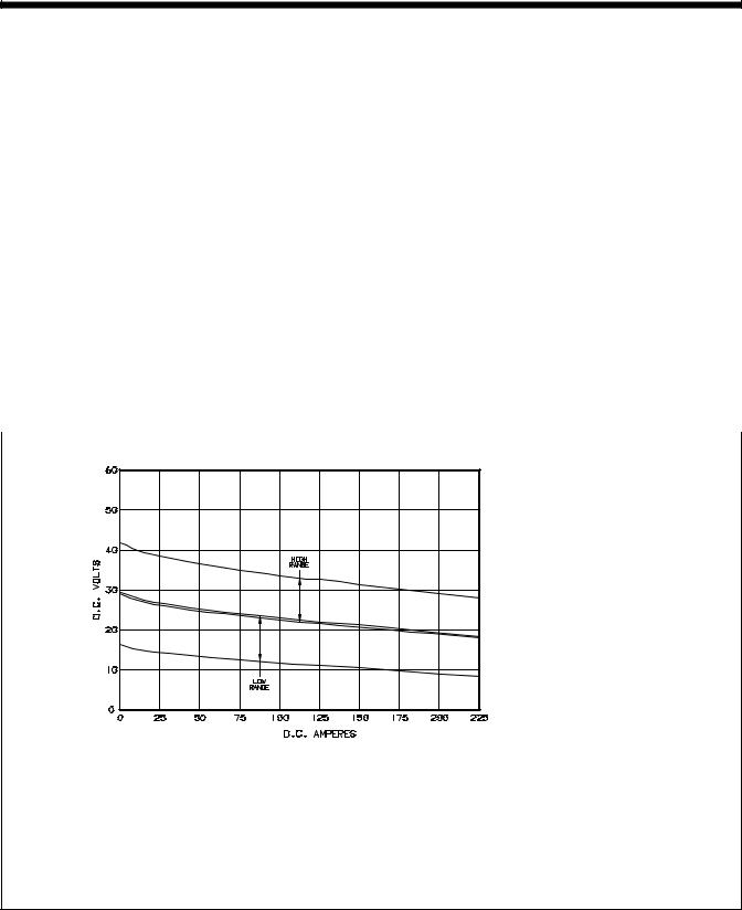
2-2. |
Volt-Ampere Curve |
|
|
|
|
|
|
|
|
|
|
|
|
|
||||
|
|
|
|
|
|
|
|
|
|
|
|
|
|
|||||
|
|
|
|
|
|
|
|
|
|
|
|
|
The volt-ampere curves show the |
|||||
|
|
|
|
|
|
|
|
|
|
|
|
|
minimum and |
maximum voltage |
||||
|
|
|
|
|
|
|
|
|
|
|
|
|
and amperage output capabilities of |
|||||
|
|
|
|
|
|
|
|
|
|
|
|
|
the welding power source. Curves |
|||||
|
|
|
|
|
|
|
|
|
|
|
|
|
of other settings fall between the |
|||||
|
|
|
|
|
|
|
|
|
|
|
|
|
curves shown. |
|
|
|
||
ssb1.1 10/91 – SB-049 424-C
OM-157 066 Page 5

2-3. Welding Power Source Duty Cycle And Overheating |
|
|
|
|
|
Duty Cycle is percentage of 10 |
|||
|
minutes that unit can weld at rated |
|||
|
load without overheating. |
|
||
|
If unit overheats, |
thermostat(s) |
||
|
opens, output stops, and cooling |
|||
|
fan runs. Wait fifteen minutes for |
|||
|
unit to cool. Reduce amperage or |
|||
|
voltage, or duty cycle before |
|||
|
welding. |
|
|
|
|
Y Exceeding duty cycle |
can |
||
|
damage |
unit |
and |
void |
|
warranty. |
|
|
|
60% Duty Cycle At 200 Amperes |
|
|
|
|
6 Minutes Welding |
4 Minutes Resting |
|
|
|
Overheating |
|
|
|
|
0 |
A or V |
|
|
|
|
|
|
|
|
|
15 |
|
|
|
|
OR |
|
|
|
Minutes |
Reduce Duty Cycle |
|
|
|
|
duty1 4/95 – SB-150 215 |
|||
2-4. Welding Gun Duty Cycle And Overheating
CAUTION |
WELDING LONGER THAN RATED DUTY CYCLE can damage gun and void warranty. |
|
|
• |
Do not weld at rated load longer than shown below. |
|
• |
Using gasless flux cored wire reduces gun duty cycle. |
warn7.1 8/93 |
Definition
0
10
Minutes
Duty Cycle is percentage of 10 minutes that gun can weld at rated load without overheating.
.023 To .045 in (0.6 To 1.1 mm) Hard Or Flux Cored Wires
100% Duty Cycle At 200 Amperes
Using CO2
100% Duty Cycle At 150 Amperes
Using Mixed Gases
Continuous Welding
.023 To .045 in (0.6 To 1.1 mm) Hard Or Flux Cored Wires
60% Duty Cycle At 300 Amperes
Using CO2
60% Duty Cycle At 200 Amperes
Using Mixed Gases
6 Minutes Welding |
4 Minutes Resting |
|
SB1.1 8/93 |
OM-157 066 Page 6
2-5. Installing Work Clamp
1 |
Work Cable |
2 |
Boot |
Slide boot onto work cable. Route |
|
cable out front panel opening from |
|
inside. |
|
4 |
Negative (–) Output Terminal |
3 |
|
Connect cable to terminal and |
|
cover connection with boot. |
|
5 |
Hardware |
4 |
|
5 |
Work Clamp |
Route cable through clamp handle |
|
|
1 |
and secure as shown. |
2 |
|
|
|
Close door. |
|
|
|
Tools Needed:
3
1/2, 3/4 in
ST-800 918-C
2-6. Installing Gas Supply
7 
6 |
5 |
4 |
1
2
3
Tools Needed:
5/8, 1-1/8 in
1Cylinder Rack
2Chain
Obtain gas cylinder and chain cylinder to rack.
3Gas Hose Fitting
4CO2 Washer
5Regulator
Install washer and regulator onto cylinder.
6 Gas Hose Connection
Obtain gas hose with fittings and install between regulator and welding power source.
7 Flow Adjust
Typical flow rate is 20 cfh (cubic feet per hour).
ST-154 623-A / Ref. ST-109 492
OM-157 066 Page 7
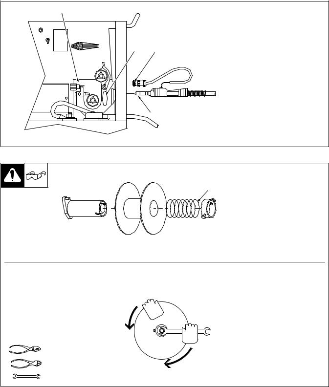
2-7. Installing Welding Gun
1
2 4
3
2-8. Installing Wire Spool And Adjusting Hub Tension
1Drive Assembly
2Gun Securing Knob
3Gun End
Loosen securing knob. Insert gun end through opening until it bottoms against drive assembly. Tighten nut.
4 Gun Trigger Plug
Insert plug into receptacle, and tighten threaded collar.
Close door.
Ref. ST-800 921-C
Use compression spring with 8 in (200 mm) spools.
When a slight force is needed to turn spool, tension is set.
Tools Needed:
15/16 in
ST-072573-B
OM-157 066 Page 8
 Loading...