

Page 1

User Manual
Network Camera
User Manual
V6.07
F
Page 2

Thank you for purchasing our product. If there is any question or request, please do not hesitate
Milesight H.264 Network Camera
Type
Megapixel
1.3MP
2.0MP
3.0MP
Mini Dome Camera
MS-C2181-PA
MS-C3581-PA
MS-C3586-PA
IR Mini Dome Camera
MS-C2182-PA
MS-C3582-PA
MS-C3587-PA
Vandal-proof Mini Dome
MS-C2173-PA
MS-C3373-PA
MS-C3573-PA
MS-C3377-PA
MS-C3577-PA
Wi-Fi Mini Cube Camera
MS-C2191-PWA
-
MS-C3596-PWA
Mini Bullet Camera
MS-C2163-PNA
MS-C3263-PNA
MS-C3363-PNA
MS-C3367-PNA
MS-C3567-PNA
Remote Focus&Zoom
Mini Bullet Camera
MS-C2163-F(I)PNA
MS-C3263-F(I)PNA
MS-C3363-F(I)PNA
MS-C3367-F(I)PNA
MS-C3567-F(I)PNA
Remote Focus&Zoom
Pro Bullet Camera
MS-C2162-F(I)PNA
MS-C3262-F(I)PNA
MS-C3362-F(I)PNA
MS-C3366-F(I)PNA
MS-C3566-F(I)PNA
Remote Focus&Zoom
Pro Dome Camera
MS-C2172-F(I)PNA
MS-C3272-F(I)PNA
MS-C3372-F(I)PNA
MS-C3376-F(I)PNA
MS-C3576F(I)PNA
Remote Focus&Zoom
Pro Dome(M) Camera
MS-C2172-F(I)PMNA
MS-C3272-F(I)PMNA
MS-C3372-F(I)PMNA
MS-C3376-F(I)PMNA
MS-C3576-F(I)PMNA
Day&Night Pro
Box Camera
MS-C2151-PA
-
MA-C3356-PA
MS-C3556-PA
to contact your dealer.
This manual is applicable to the Milesight H.264&H.265 Network Camera, series shown as follows,
except where otherwise indicated.
Page 3

This Manual explains how to use and manage Milesight network cameras on your network.
Milesight H.265 Network Camera
Type
Megapixel
2.0MP
3.0MP
4.0MP
IR Mini Dome
Network Camera
MS-C2982-PB
-
MS-C4482-PB
Vandal-proof Mini Dome
Network Camera
MS-C2973-PB
-
MS-C4473-PB
Mini Bullet Camera
MS-C2963-PB
MS-C3763-PB
MS-C4463-PB
Remote Focus&Zoom
Mini Bullet Camera
MS-C2963-F(I)PB
MS-C3763-F(I)PB
MS-C4463-F(I)PB
Remote Focus&Zoom
Pro Bullet Camera
MS-C2862-F(I)PB
MS-C2962-(R)F(I)PB
MS-C3762-F(I)PB
MS-C4462-F(I)PB
Remote Focus&Zoom
Pro Dome Camera
MS-C2972-F(I)PB
MS-C3772-F(I)PB
MS-C4472-F(I)PB
Remote Focus&Zoom
Pro Dome(M) Camera
MS-C2972-F(I)PMB
MS-C3772-F(I)PMB
MS-C4472-F(I)PMB
Day&Night Pro Box
Network Camera
MS-C2951-FB
MS-C3751-FB
MS-C4451-FB
Previous experience of networking will be of use when using the products. Please read this manual
carefully before operation and retain it for future reference.
This manual may contain several technically incorrect places or printing errors, and the content is
subject to change without notice. The updates will be added into the new version of this manual.
We will readily improve or update the products or procedures described in the manual.
Copyright Statement
This manual may not be reproduced in any form or by any means to create any derivative such
as translation, transformation, or adaptation without the prior written permission of Milesight
Technology Co., Ltd(Hereinafter referred to as Milesight).
Milesight reserves the right to change this manual and the specifications without prior notice.
The latest specifications and user documentation for all Milesight products are available on our
official website
www.milesight.com
Page 4

Industry Canada ICES-003 Compliance:
Warnings: Please follow these safeguards to
prevent injury or death.
Cautions: Please follow these safeguards to
prevent potential injury or material damage.
This installation must be conducted by a qualified service person and should strictly
To avoid risk of fire and electric shock, do keep the product away from rain and moisture
Do not touch components such as heat sinks, power regulators, and processors, which
Source with DC 12V or PoE
Please make sure the plug is firmly inserted into the power socket
When the product is installed on a wall or ceiling, the device should be firmly fixed
If the product does not work properly, please contact your dealer. Never attempt to
Make sure that the power supply voltage is correct before using the camera
Do not store or install the device in extremely hot or cold temperatures, dusty or damp
Only use components and parts recommended by manufacturer
Do not drop the camera or subject it to physical shock
To prevent heat accumulation, do not block air circulation around the camera
Laser beams may damage image sensors. The surface of image sensors should not be
Use a blower to remove dust from the lens cover
Use a soft, dry cloth to clean the surface of the camera. Stubborn stains can be removed
This Class B digital apparatus complies with Canadian ICES-003.
Cet appareil numerique de la classe B est conforme a la norme NMB-003 du Canada.
Safety Instruction
These instructions are intended to ensure that user can use the product correctly to avoid danger
or property loss. The precaution measures are divided into “Warnings” and “Cautions”
Warnings: Serious injury or death may be caused if any of these warnings is neglected.
Cautions: Injury or equipment damage may be caused if any of these cautions are neglected.
Warnings
comply with the electrical safety regulations of the local region
before installed.
may be hot
disassemble the camera by yourself
Cautions
locations, and do not expose it to high electromagnetic radiation
exposed to where a laser beam equipment is used
using a soft cloth dampened with a small quantity of detergent solution, then wipe dry
Page 5
Do not use volatile solvents such as alcohol, benzene or thinners as they may damage the
surface finishes
Save the package to ensure availability of shipping containers for future transportation
2012/19/EU (WEEE directive): Products marked with this symbol cannot be disposed
of as unsorted municipal waste in the European Union. For proper recycling, return
this product to your local supplier upon the purchase of equivalent new equipment,
or dispose of it at designated collection points. For more information
see:www.recyclethis.info.
2006/66/EC (battery directive): This product contains a battery that cannot be
disposed of as unsorted municipal waste in the European Union. See the product
documentation for specific battery information. The battery is marked with this
symbol, which may include lettering to indicate cadmium (Cd), lead (Pb), or
EU Conformity Statement
mercury(Hg). For proper recycling, return the battery to your supplier or to a designated
collection point. For more information see:www.recyclethis.info.
Page 6

Table of Contents
Chapter I Product Description
1.1 Product Overview
1.2 Key Features
1.3 Hardware Overview
1.4 Hardware Installation
1.5 How to Connect to Alarm Interface
1.6 System Requirements
Chapter II Network Connection
2.1 Setting the Camera over the LAN
2.1.1 Connect the Camera to the PC Directly
2.1.2 Connect via a Switch or a Router
2.2 Dynamic IP Connection
Chapter III Accessing the Network Camera
3.1 Assigning An IP Address
3.1.1 Assigning An IP Address Using Smart Tools
3.1.2 Assign An IP Address via Browser
3.2 Accessing from the Web Browser
3.2.1 Access over IE Browser
3.3 Accessing from Milesight VMS (Video Management Software)
Chapter IV System Operation Guide
...................................................................................................................................
....................................................................................................................
..........................................................................................................................
.......................................................................................................................
..................................................................................................................
...........................................................................................
.................................................................................................................
...............................................................................................................
...............................................................................................
..........................................................................
.....................................................................................
...............................................................................................................
.............................................................................................
..............................................................................................................
....................................................................
....................................................................................
..............................................................................................
.....................................................................................................
........................................................................................................
..............................................
1
1
1
2
12
28
28
29
29
29
29
29
31
31
31
34
35
35
37
38
4.1 Live Video
4.2 Playback
4.3 Basic Settings
4.3.1 Video
4.3.2 Image
4.3.3 Audio
4.3.4 Wi-Fi
4.3.5 Network
4.3.6 Date&Time
4.4 Advanced Settings
4.4.1 Image
4.4.2 Network
4.4.3 Alarm
4.4.4 Storage
4.4.5 Security
4.4.6 SIP
4.4.7 Logs
4.5 System
4.6 Maintenance
Chapter V Services
........................................................................................................................................
..........................................................................................................................................
.....................................................................................................................................
...............................................................................................................................
..................................................................................................................................
.................................................................................................................................
..................................................................................................................................
...................................................................................................................................
.............................................................................................................................
.........................................................................................................................
.......................................................................................................................
.................................................................................................................................
.............................................................................................................................
..................................................................................................................................
...............................................................................................................................
..............................................................................................................................
.......................................................................................................................................
....................................................................................................................................
................................................................................................................................
.....................................................................................................................................
38
40
42
42
43
48
49
50
53
54
54
55
60
67
71
72
75
75
76
78
Page 7

1
Chapter I Product Description
Based on Linux OS with high reliability
H.265/H.264/MJPEG video compression capability
Support ONVIF Profile S
Support three streams
Support PoE
ICR filter with auto switch, true day/night
Built-in WEB server, support IE/ Firefox/ Chrome/ Safari browser
UPnP protocol for the easy management of IPC
Motion Detection, Privacy Masking, Network Fault Detection and ROI
FTP upload, SMTP upload, SD card record and SIP phone
G.711/AAC audio compression capability
Alarm I/O(built-in for bullet and box cameras, optional for dome cameras)
Built-in Microphone(built-in for (IR) Mini Dome and Vandal-proof Mini Dome, optional for
Real-time video electronic amplification
Three-privilege levels of users for flexible management
Micro SD/SDHC/SDXC card local storage support, expand the edge storage
Local PAL/NTSC signal output
1.1 Product Overview
Milesight provides a consistent range of cost-effective and reliable network cameras to fully
meet your requirements. Based on embedded Linux operating system, Milesight network
cameras could be easily accessed and managed either locally or remotely with great reliability.
Built-in high-performance DSP video processing modules, the cameras pride on low power
consumption and high stability. They support state-of-the-art H.265/H.264/MJPEG video
compression algorithm and industry-leading HD dual-stream technology to achieve the highest
level of video image quality under the limited network resources. It is fully functional, supporting
for flexible and comprehensive alarm linkage mechanism, day and night auto switch, smart PTZ
control and privacy masking, etc.
In practical applications, Milesight network cameras could either work independently in the LAN,
or be networked to form a powerful safety monitoring system. It is widely used in fields such as
finance, education, industrial production, civil defense, health care for security’s sake.
1.2 Key Features
Pro Dome)
Page 8
2
1.3 Hardware Overview
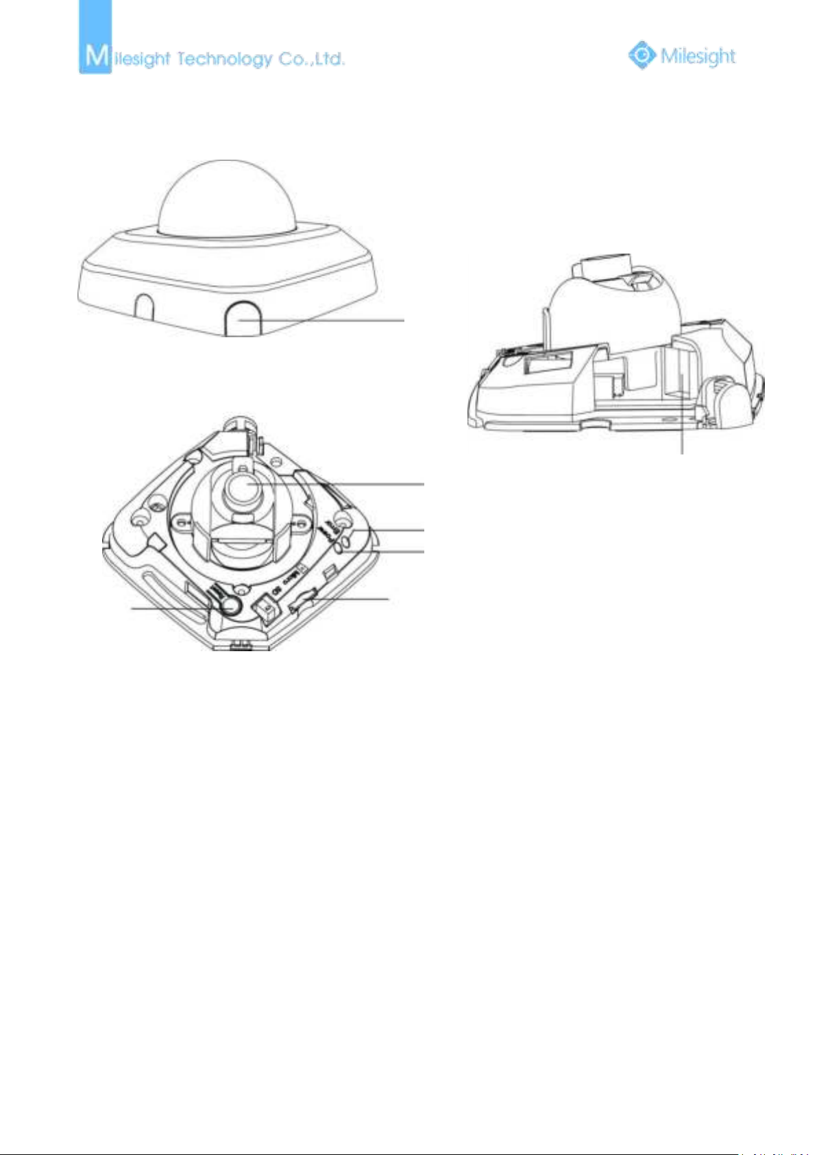
1. Mini Dome Network Camera
Press Button
Ethernet Port (PoE)
Lens
Error LED Indicator
Power LED Indicator
Micro SD/SDHC/SDXC Card Slot
Reset
1) Error LED Indicator: Error LED Indicator is on when the device starts up or runs error.
2) Reset Button: Press “Reset” button for 5 seconds, the device will be restored to factory
3) Only PoE is available for power supply.
Note:
Figure 1-3-1 Mini Dome Network Camera
default.
Page 9
3
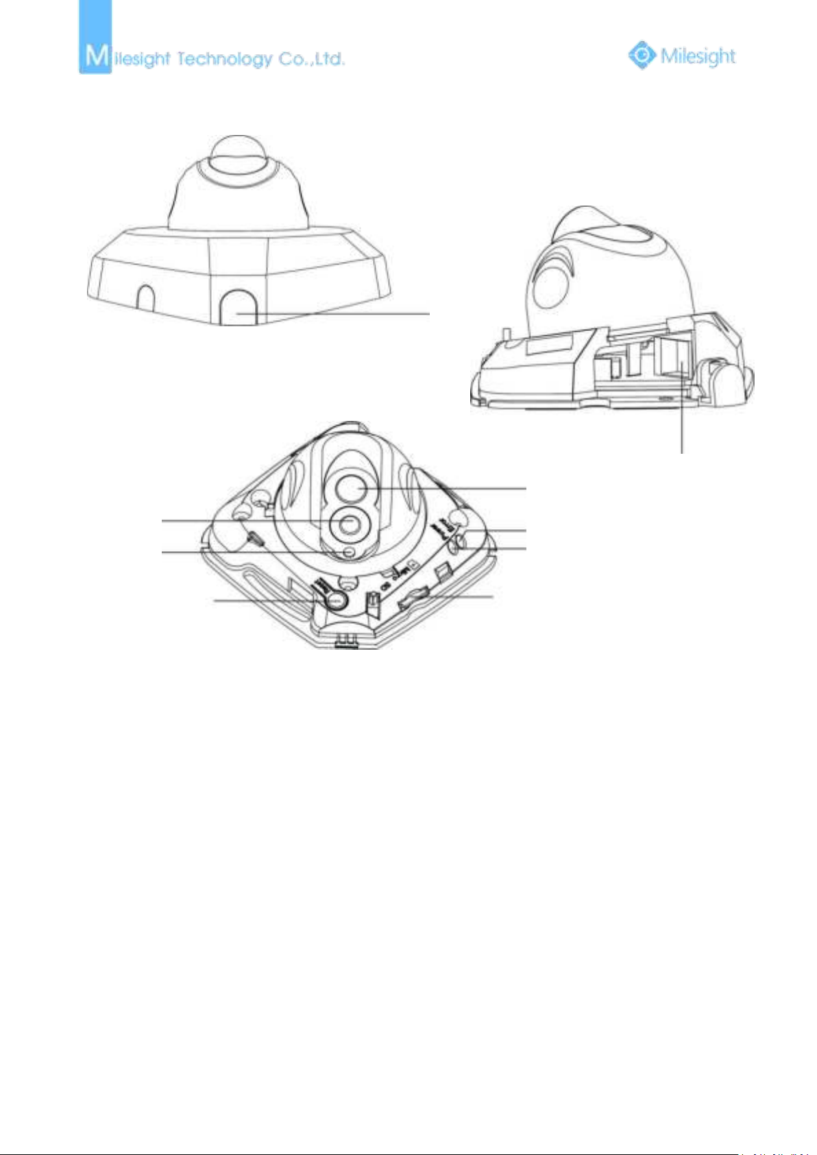
2. IR Mini Dome Network Camera
Ethernet Port (PoE)
Lens
Press Button
Error LED Indicator
Power LED Indicator
Micro SD/SDHC/SDXC Card Slot
Reset
IR LEDs
Light Sensor
Note:
1) Error LED Indicator: Error LED Indicator is on when the device starts up or runs error.
2) Reset Button: Press “Reset” button for 5 seconds, the device will be restored to factory
3) Only PoE is available for power supply.
Figure 1-3-2 IR Mini Dome Network Camera
default.
Page 10
4
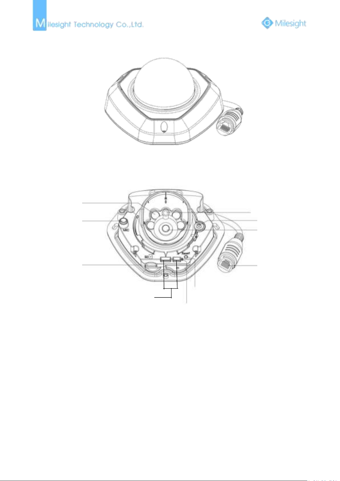
3. Vandal-proof Mini Dome Network Camera
Figure 1-3-3
1) Error LED Indicator: Error LED Indicator is on when the device starts up or runs error.
2) Reset Button: Press “Reset” button for 5 seconds, the device will be restored to factory
3) Only PoE is available for power supply.
IR LEDs
Microphone
Micro SD/SDHC/SDXC
Card Slot
Power and System LED Indicator
Reset
Ethernet Port
(PoE)
Lens
Screw
Light Sensor
Debug Ports
Note:
default.
Figure 1-3-4 Vandal-proof Mini Dome Network Camera
Page 11
5
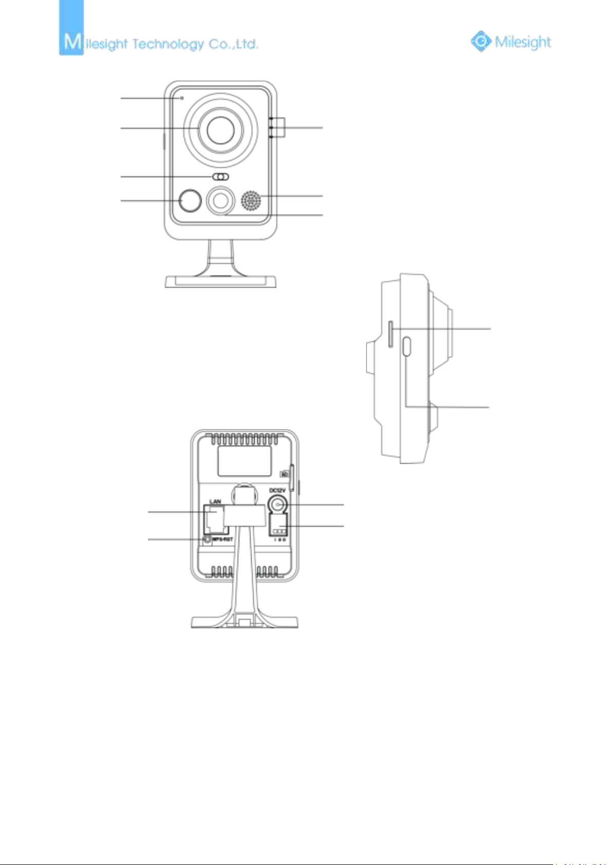
4. Wi-Fi Mini Cube Network Camera
Note:
1) SIP Button: Trigger alarm via SIP calling. After this button is pressed, the camera will call the SIP
2) WPS Button: Press this button, and then press the WPS button on your router to set up
3) DC 12V and PoE are available for power supply;
Microphone
Lens
Light Sensor
IR LEDs
LED Indicators
Speaker
PIR Sensor or SIP Button
Micro SD/SDHC/SDXC
Card Slot
SIP Button
Ethernet Port(PoE)
WPS/Reset Button
Power Connector
Alarm Input/Output
Phone.
wireless connection automatically.
Figure 1-3-5 Wi-Fi Mini Cube Network Camera
Page 12

6
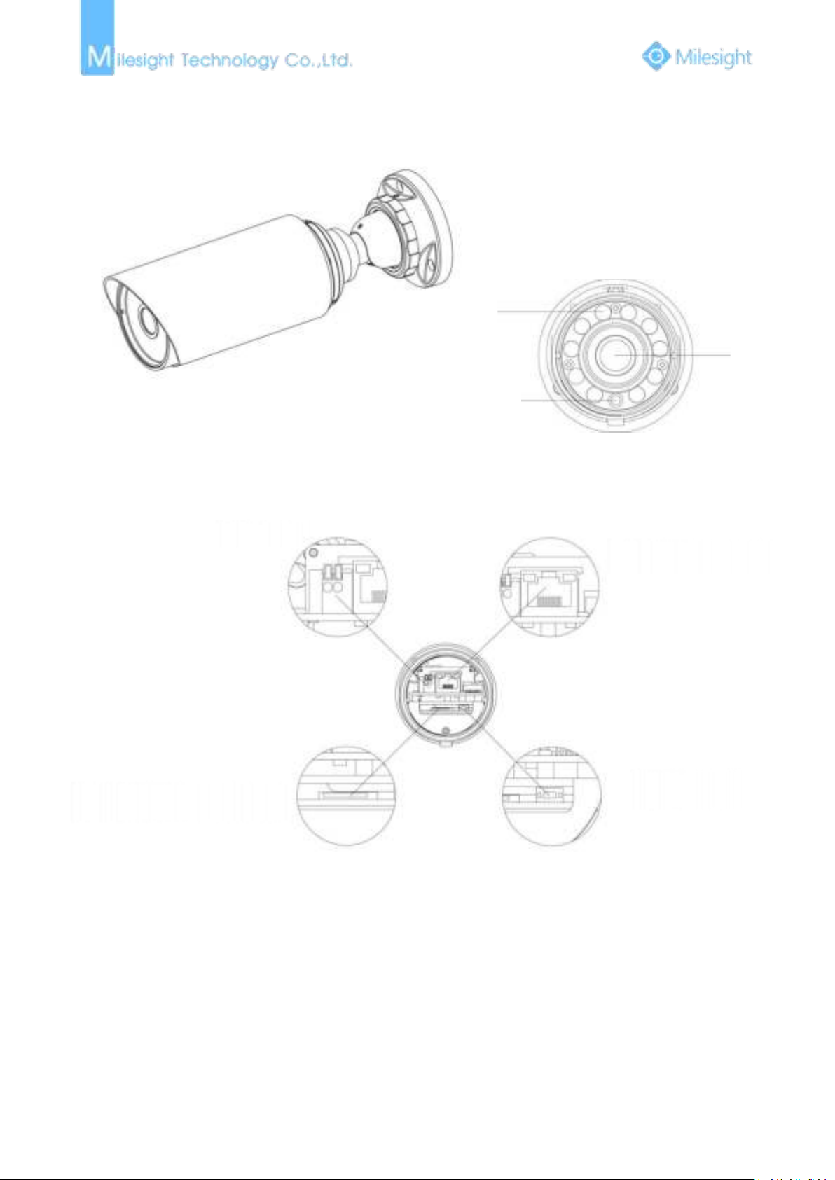
5. Mini Bullet Network Camera
Note:
1) Only PoE is available for power supply.
IR LEDs
Light Sensor
Lens
Ethernet Port(PoE)
Micro SD/SDHC/SDXC Card Slot
Reset Button
Figure 1-3-6 Mini Bullet Network Camera
Page 13
7
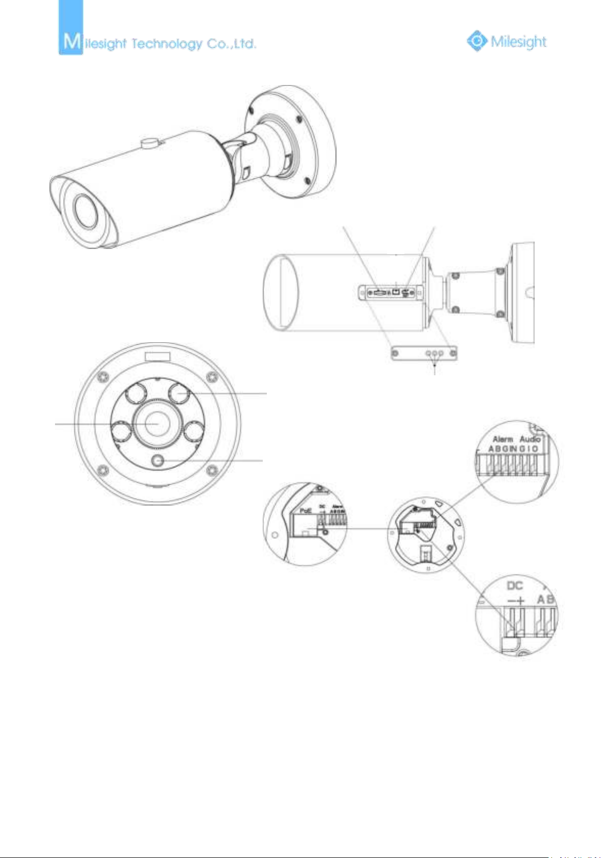
6. Remote Focus&Zoom Mini Bullet Network Camera
Note:
1) DC 12V and PoE are available for power supply.
IR LEDs
Light Sensor
Lens
DC 12V
Ethernet Port(PoE)
Micro SD/SDHC/SDXC Card Slot
Reset Button
Figure 1-3-7 Remote Focus&Zoom Mini Bullet Network Camera
Page 14
8
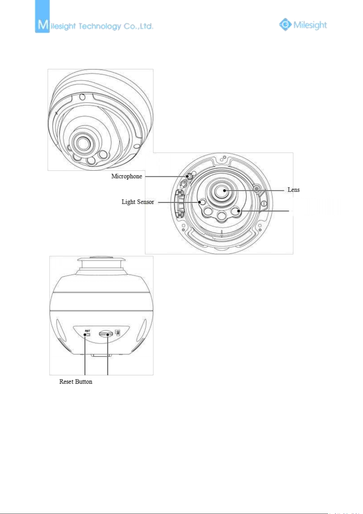
7. Pro Bullet Network Camera
Note:
1) DC 12V and PoE are available for power supply.
Ethernet Port (PoE)
Alarm /Audio
Power Connector
Lens
Light Sensor
IR LEDs
Micro SD/SDHC/SDXC
Card Slot
Reset
Breather
Figure 1-3-8 Pro Bullet Network Camera
Page 15
9
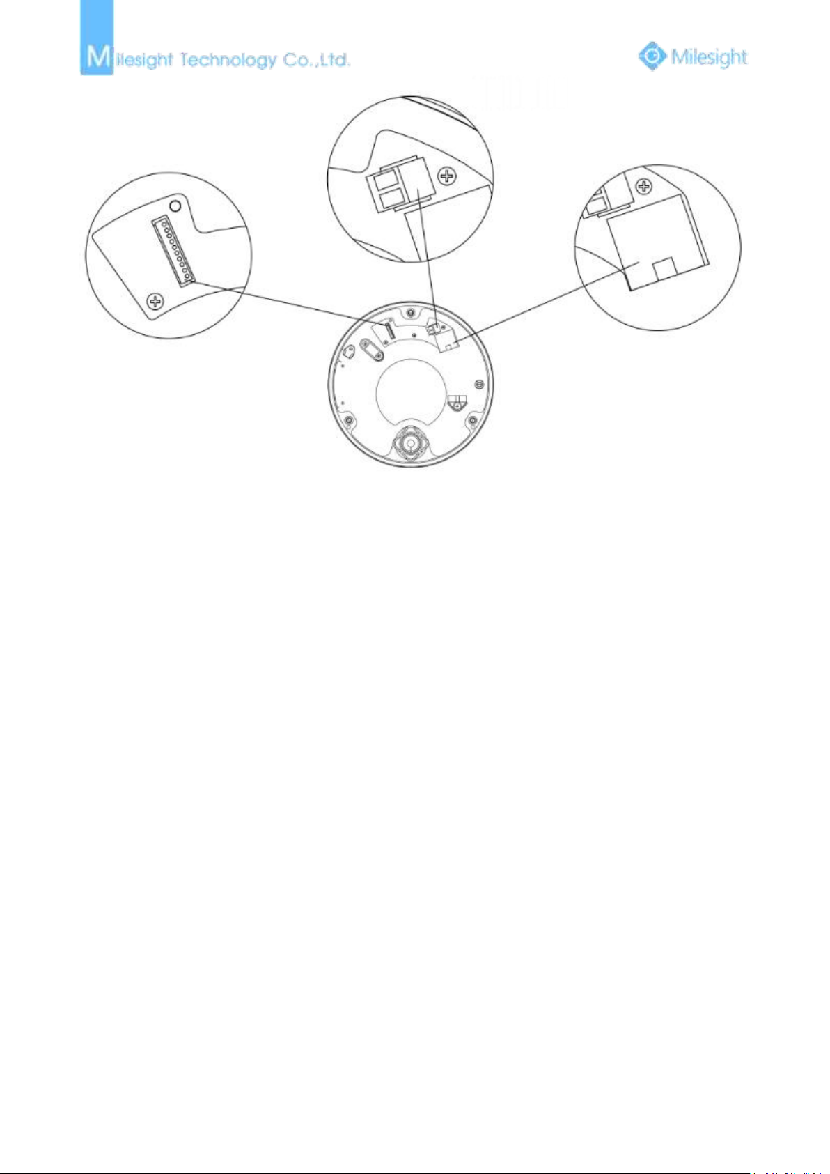
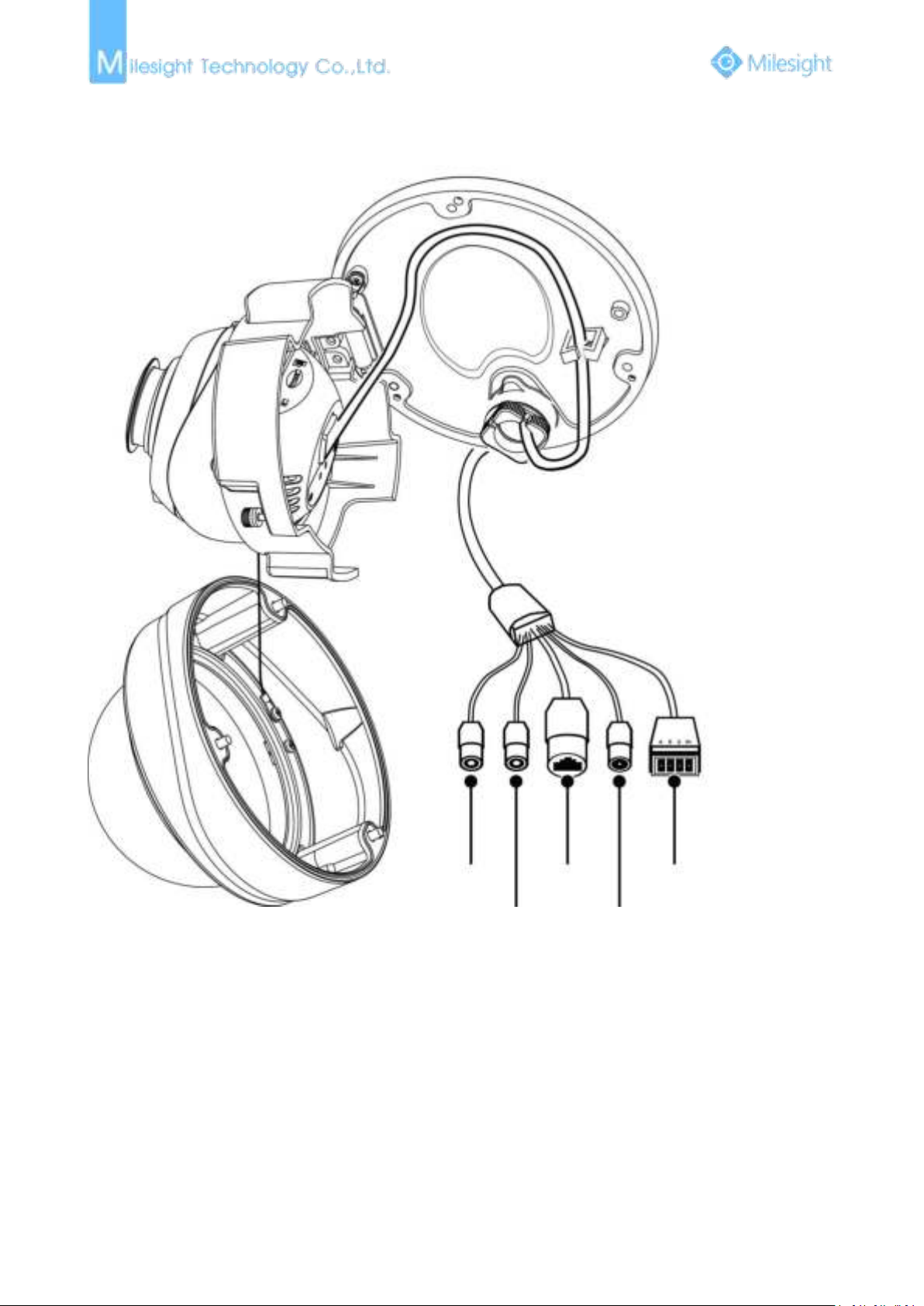
8. Pro Dome Network Camera
Note:
1) There are two versions for Pro Dome: Standard and Multiple Interface, the interface’s pictures
2) Multiple Interface adopts the external interface “Audio In” instead of the Microphone built-in;
IR LEDs
Micro SD/SDHC/SDXC Card Slot
are as following;
Page 16
10
Figure 1-3-9 Pro Dome Network Camera (Standard Interface)
DC 12V
Ethernet Port (PoE)
WAFER Contact
Page 17
11
Audio In
Audio Out
Ethernet Port
(PoE)
DC 12V
External Interface
Figure 1-3-10 Pro Dome Network Camera (Multiple Interface)
Page 18

12
1.4 Hardware Installation
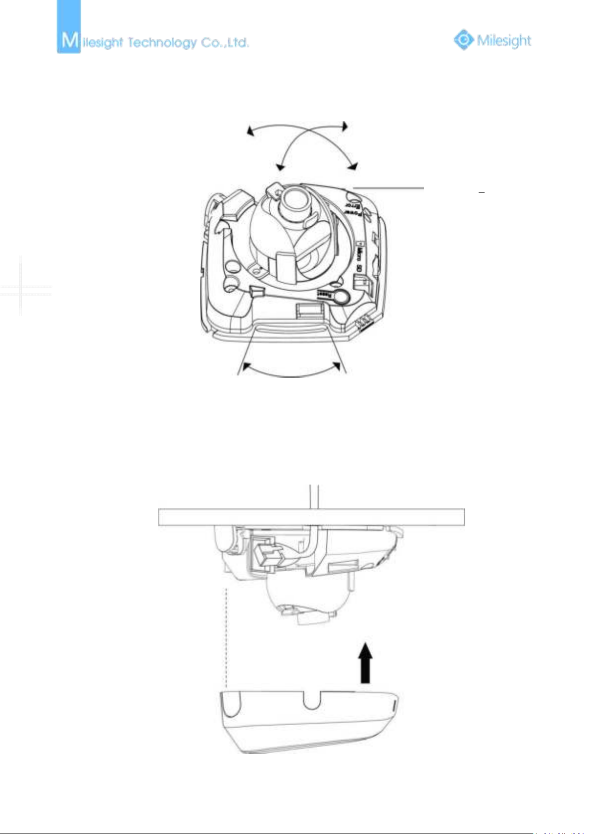
1. Mini Dome Network Camera
Press Button
Step1: Remove the dome cover;
Step2: Secure the screws;
Step3: Connect and route an Ethernet cable through the ceiling or wall;
Page 19
13
Step4: Adjust the lens angle and focus;
Pan Range:+15°
Tilt Range:0-90°
20°
Step5: Attach the dome cover;
Page 20
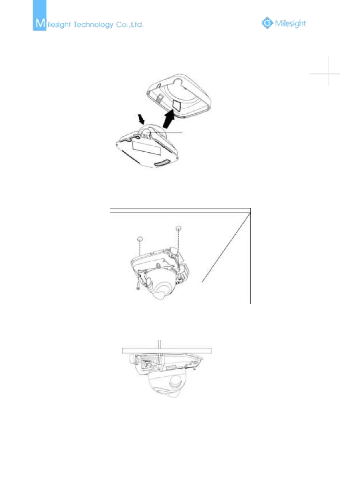
14
2. IR Mini Dome Network Camera
Step1: Remove the dome cover;
Press
Step2: Secure the screws;
Step3: Connect and route an Ethernet cable through the ceiling or wall;
Page 21
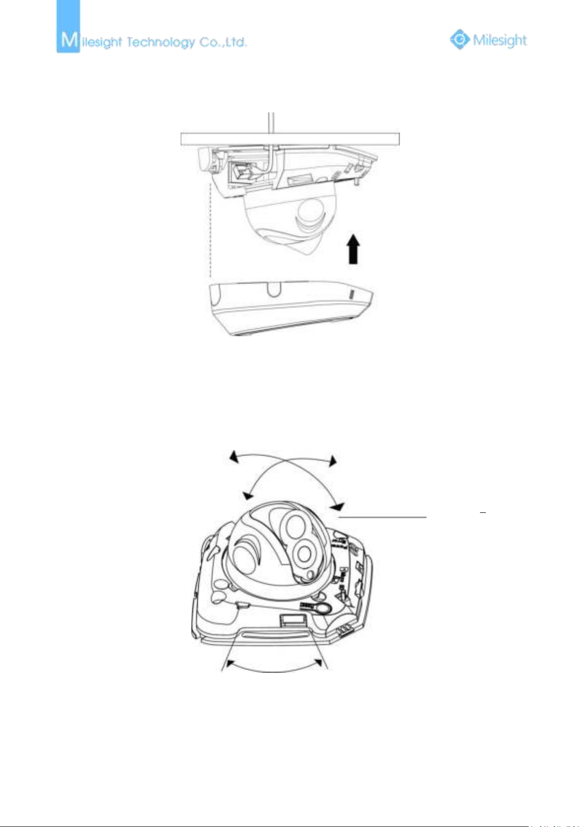
15
Step4: Attach the dome cover;
Pan Range:+17.5°
Tilt Range:20-60°
20°
Step5: Adjust the lens angle and focus;
Page 22
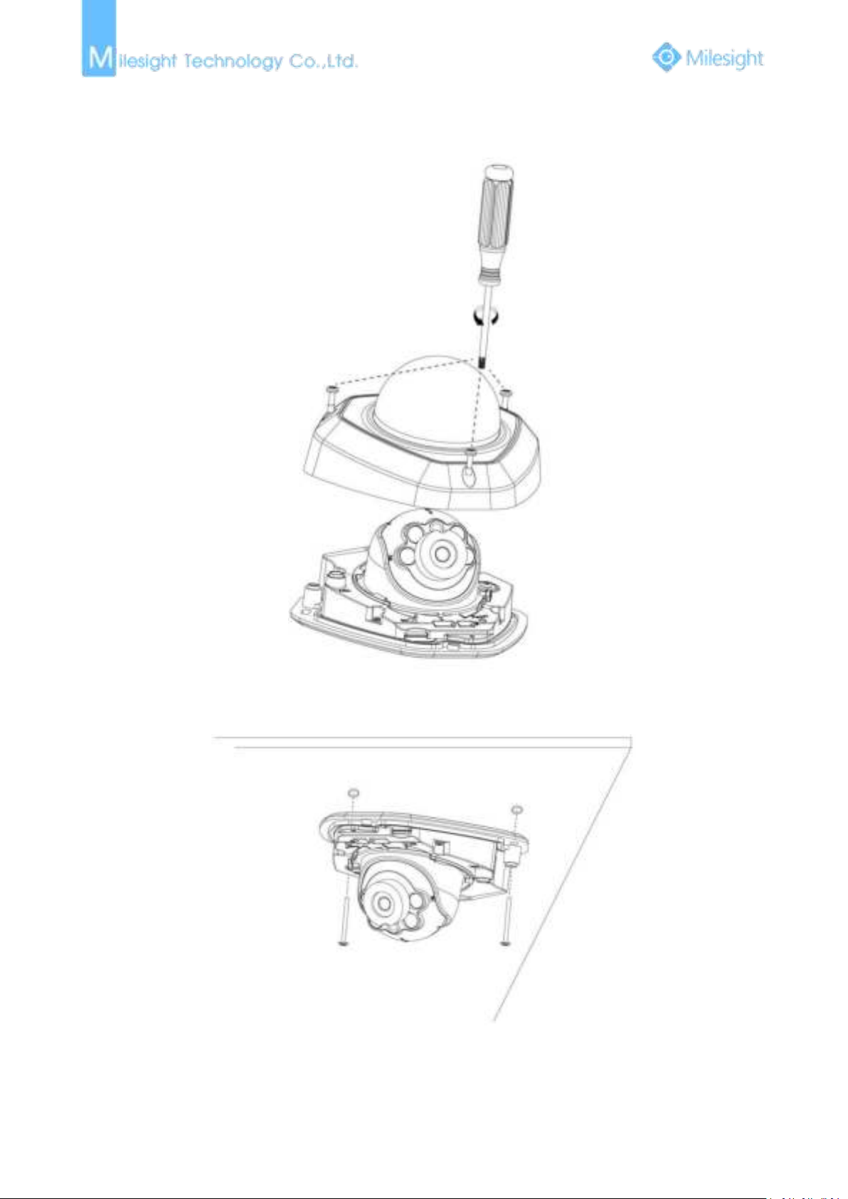
16
3. Vandal-proof Mini Dome Network Camera
Step1: Remove the dome cover;
Step2: Secure the screws;
Page 23
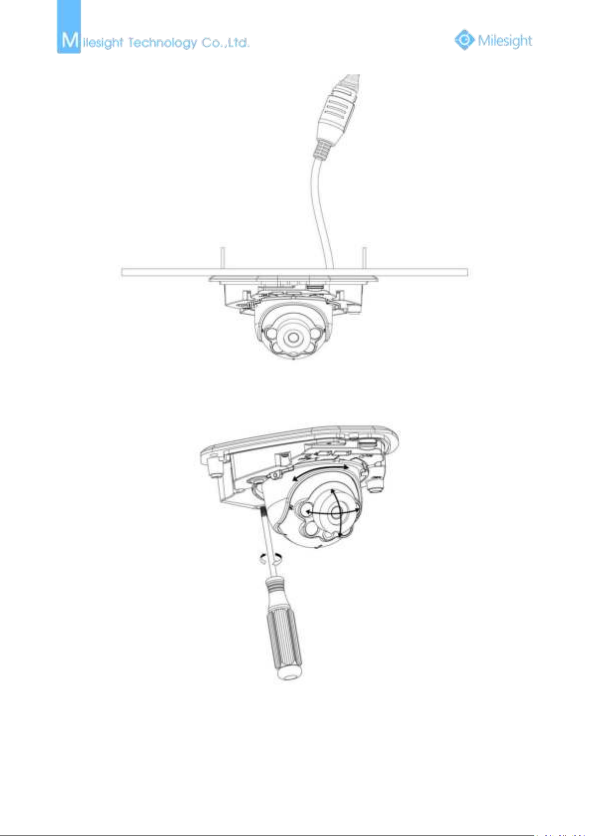
17
Step3: Connect and route an Ethernet cable through the ceiling or wall;
Step4: Loosen the screw and adjust the lens angle and focus;
Page 24
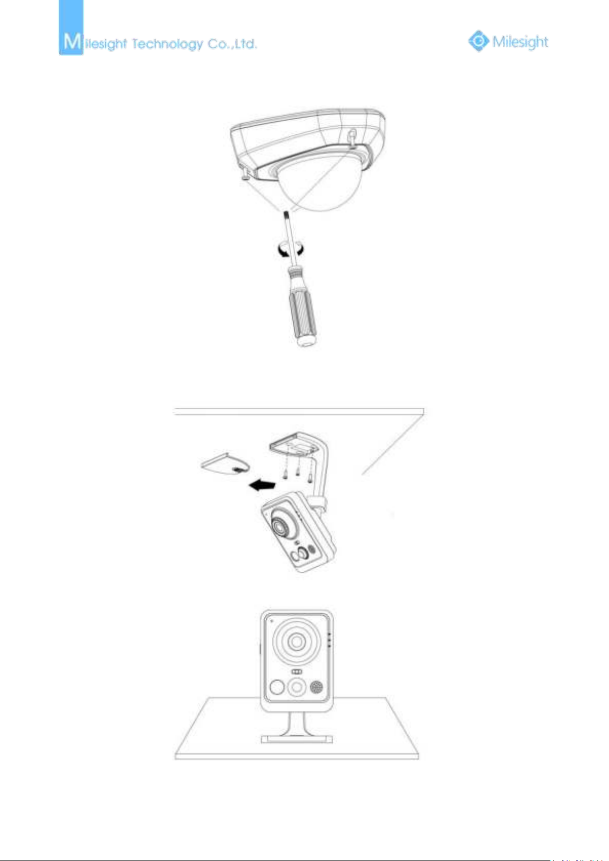
18
Step5: Attach the dome cover;
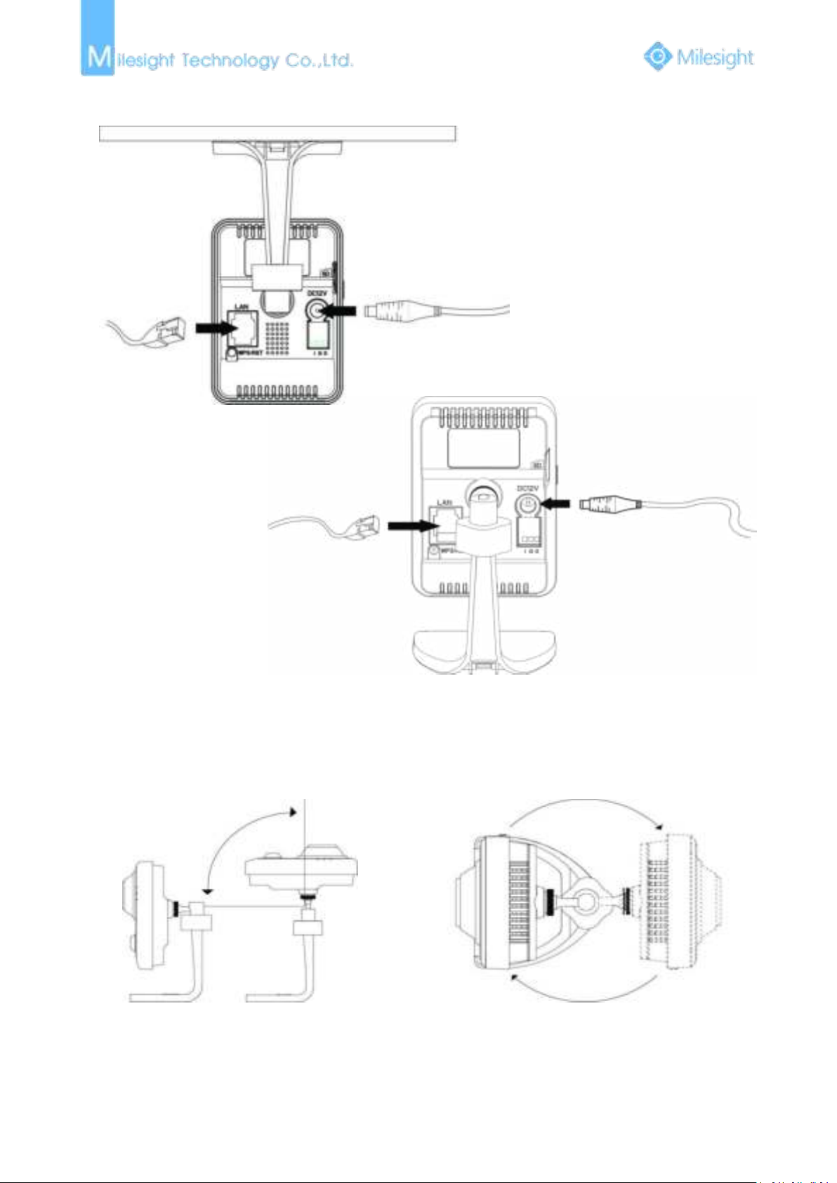
4. Wi-Fi Mini Cube Network Camera
Step1: Mount the cube camera to the ceiling or wall, or place the cube camera horizontally;
Page 25
19
Step2: Connect the power adapter and Ethernet cable;
Power Cable
Ethernet Cable
90°
360°
Step3: Adjust the shooting direction;
Page 26

20
5. Mini Bullet Network Camera
Step1: Loosen the waterproof connector, and then remove the rubber seal, and the waterproof
connector;
Step2: Loosen and open the rear cover;
Step3: Install a Micro SD/SDHC/SDXC card, connect an Ethernet cable and pass it through the
rubber seal.
Step4: Install and tighten the rear cover;
Step5: Tighten the rubber seal, seal clamp, and cap nut of the waterproof connector;
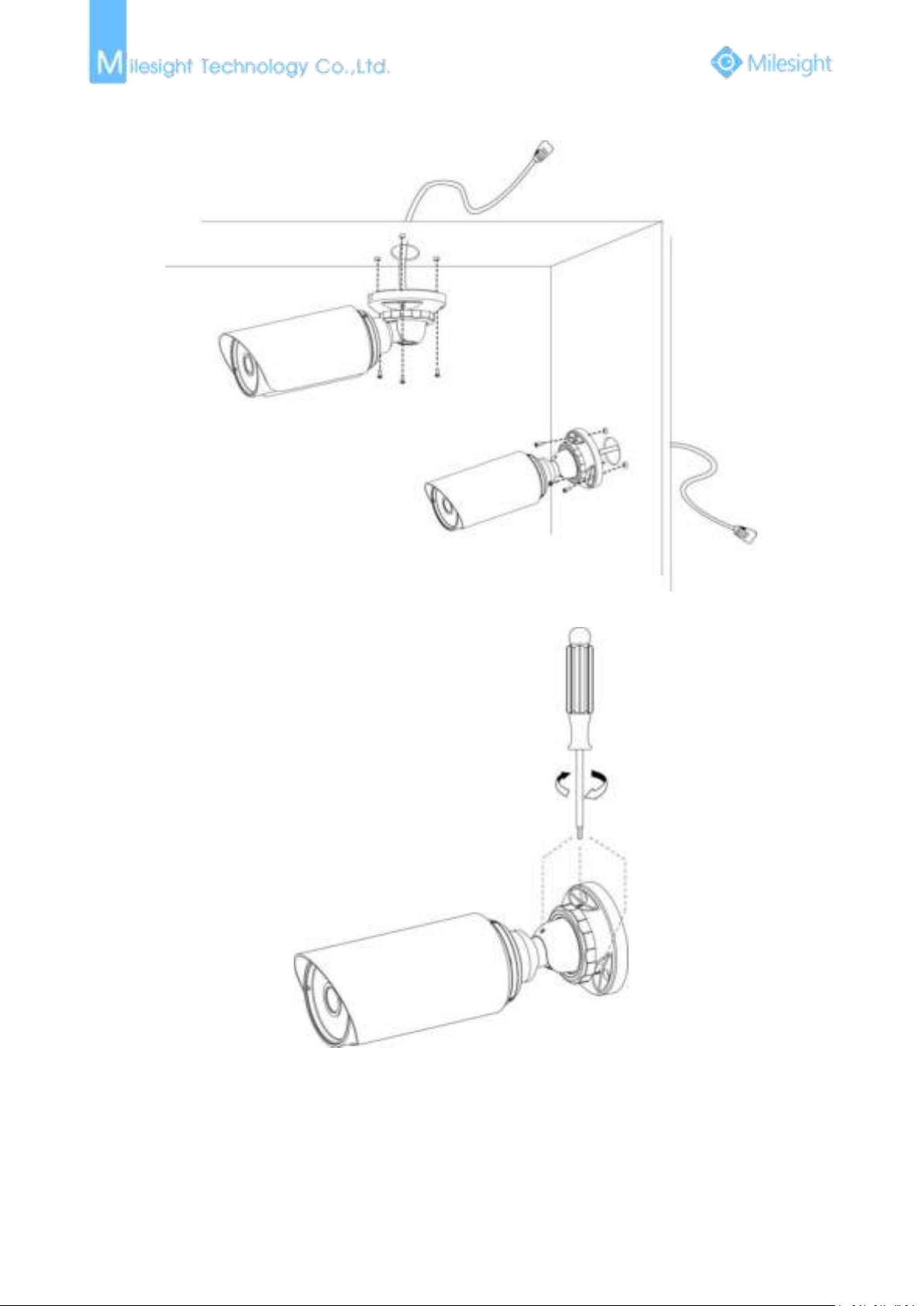
Step6: Pass the Ethernet cable through the center of the mount bracket, put the bracket and
camera together, rotate the bracket and fasten the bracket using screws;
Page 27
21
Step7: Mount the camera to the ceiling or wall;
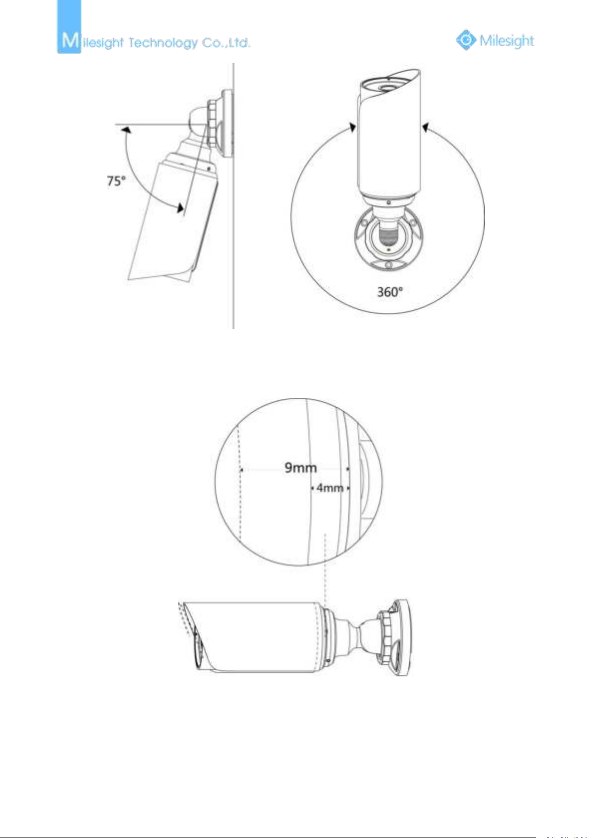
Step8: Adjust the shooting direction;
Page 28
22
Note:
1) The upper cover of the mini bullet camera could only be moved forward for 5mm at most to
ensure better field of view.
Page 29
23
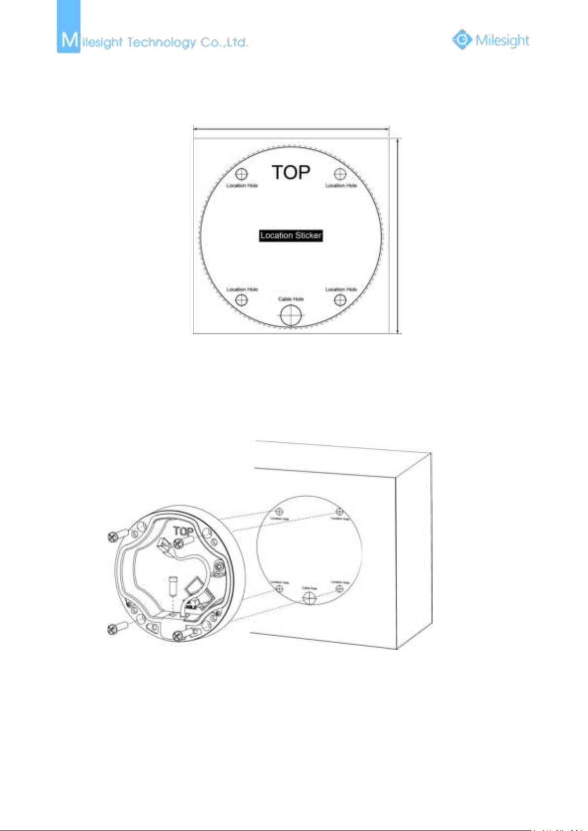
6. Pro Bullet Network Camera
Step1: Fix a sticker in the position where you want to install your camera;
Step2: Pass the Ethernet cable through the rear cover and fasten the rear cover to the ceiling or
wall;
Step3: Connect an Ethernet cable and hook for your camera with a hang rope;
Page 30
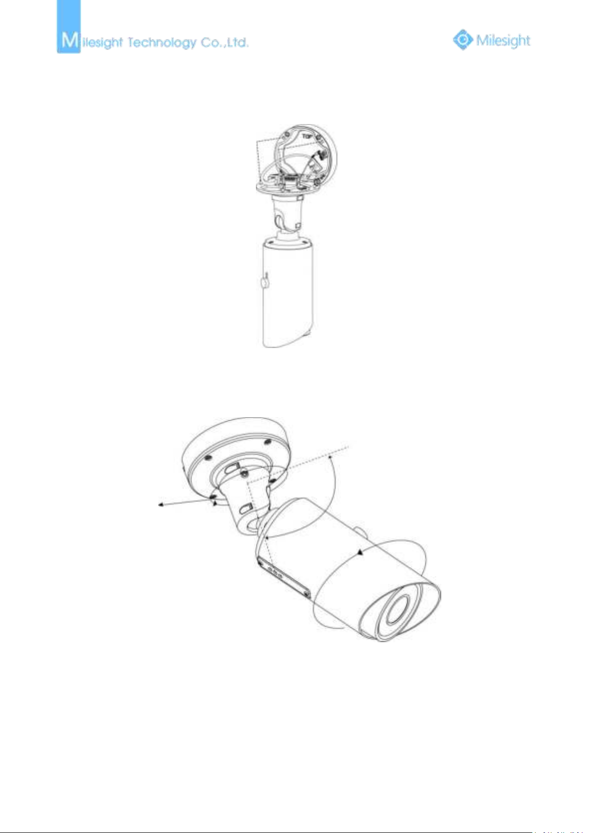
24
Step4: Install and tighten the rear cover and fasten the bracket to the camera using 4 plum flower
90°
360°
360°
head screws;
Step5: Adjust the shooting direction;
Page 31

25
7. Pro Dome Network Camera
Step1: Fix a sticker in the position where you want to install your camera. Install the supplied
bracket on the ceiling or wall, secure the screws;
Step2: Connect an Ethernet and pass it through the rubber seal;
Page 32
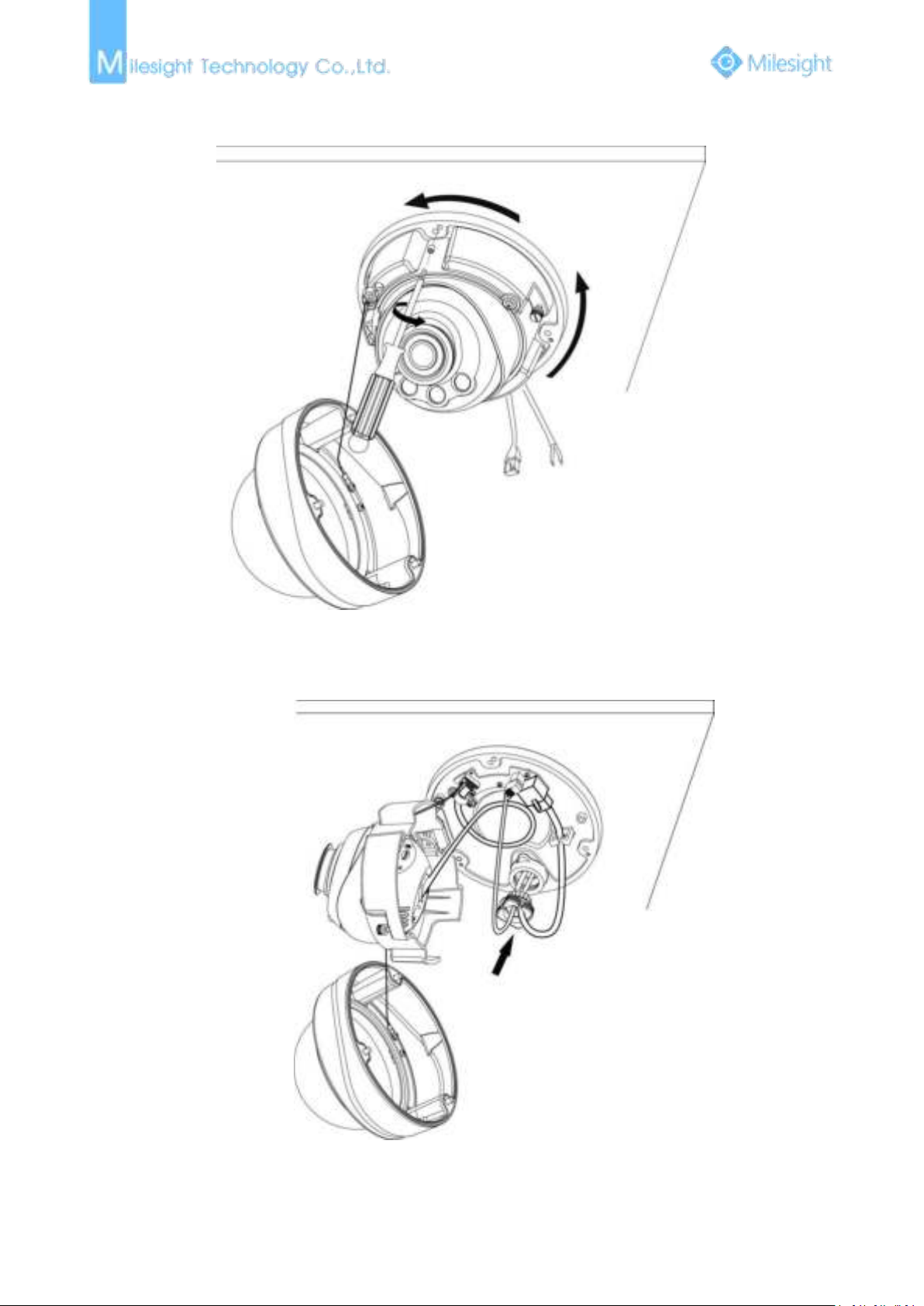
26
Step3: Rotate the camera unit according to the direction shown in the picture, and then attach the
camera unit to the bracket with the supplied screws;
Step4: Connect and route an Ethernet cable and the power source through the ceiling or wall, then
attach the camera unit to the bracket;
Page 33
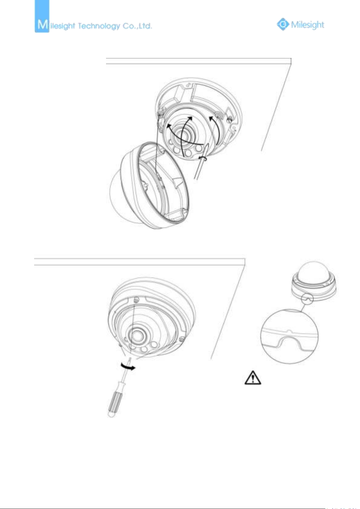
27
Step5: Loosen the camera head fixing screw. Adjust the camera to turn the lens in the desired
direction. Tighten the camera head fixing screw to fix the camera;
Step6: Attach the dome cover;
Page 34
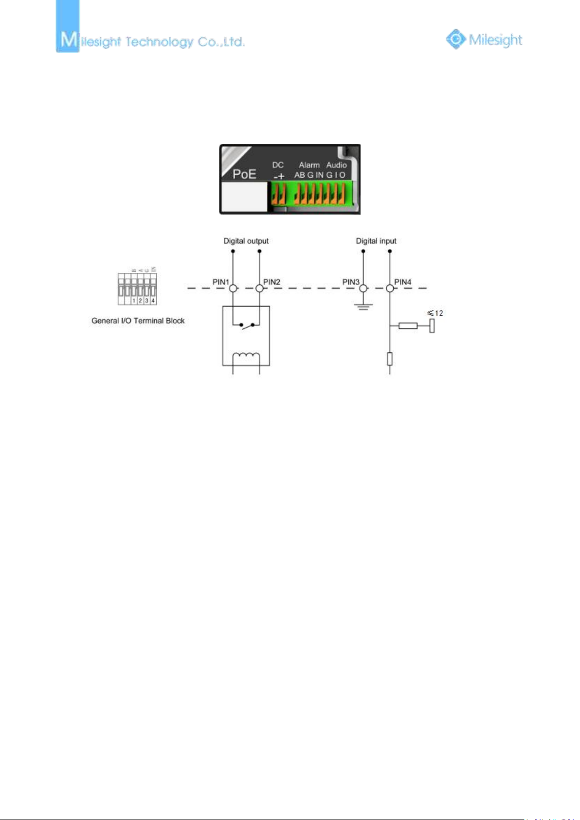
28
1.5 How to Connect to Alarm Interface
External interface of camera is as the following, you can refer to the picture to install the external
alarm device:
PIN1: Alarm Output NC/NO 24VDC 1A
PIN2: Alarm Output NC/NO 24VDC 1A
PIN3: Alarm Input NO/NC ≤12V
PIN4: Alarm Input NO/NC ≤12V
1.6 System Requirements
Operating System: Windows XP/Vista/7/8/10/Server 2000/Server 2008
CPU: 1.66GHz or higher
RAM: 1G or higher
Graphic memory: 128MB or more
Internet protocol: TCP/IP (IPv4/IPv6)
Web Browsers: Internet Explorer 8.0 and above version, Mozilla Firefox, Google Chrome and Safari.
Page 35
29
Chapter II Network Connection
Connecting the network camera via a router
2.1 Setting the Camera over the LAN
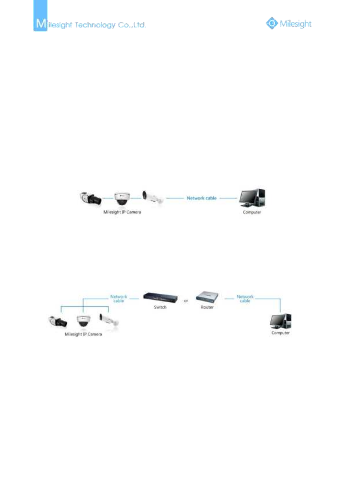
Connecting the camera to a switch or a router is the most common connection method. The
camera must be assigned an IP address that is compatible with its LAN.
2.1.1 Connect the Camera to the PC Directly
In this method, only the computer connected to the camera will be able to view the camera. The
camera must be assigned a compatible IP address to the computer. Details are shown as the
following figure.
Figure 2-1-1 Connect the camera to the PC directly
2.1.2 Connect via a Switch or a Router
Refer to the following figure to set network camera over the LAN via the switch or router.
Figure 2-1-2 Connect via a switch or a Router
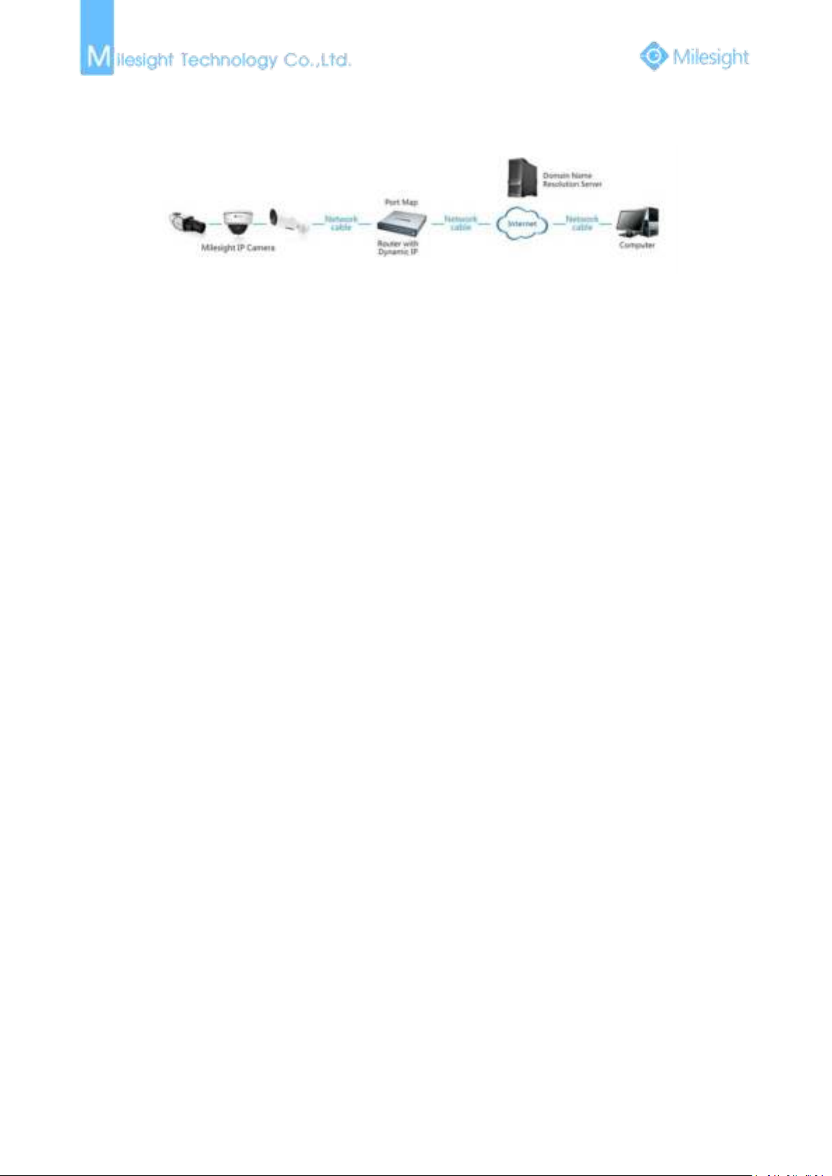
2.2 Dynamic IP Connection
Step1: Connect the network camera to a router;
Step2: On the camera, assign a LAN IP address, the Subnet mask and the Gateway;
Step3: On the router, set port forwarding. E.g. 80, 8000 and 554 ports. The steps for port
forwarding vary depending on different routers. Please look up the router's user manual for
assistance with port forwarding;
Page 36
30
Step4: Apply a domain name from a domain name provider;
Step5: Configure the DDNS settings in the setting interface of the router;
Step6: Visit the camera via the domain name.
Figure 2-2 Connect the network camera via a router using dynamic IP
Page 37
31
Chapter III Accessing the Network Camera
3.1 Assigning An IP Address
The camera must be assigned an IP address to be accessible. The default IP address of Milesight
network camera is 192.168.5.190. The default user name is “admin”, and password is “ms1234”.
You can either change the IP address of the camera via Smart Tools or browser. Please connect the
camera in the same LAN of your computer.
3.1.1 Assigning An IP Address Using Smart Tools
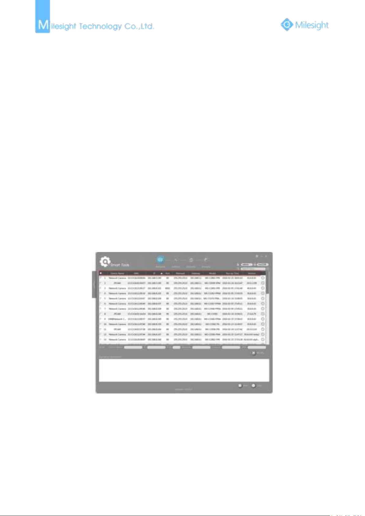
Smart Tools is a software tool which can automatically detect multiple online Milesight network
cameras connected in the LAN, set IP addresses, and manage firmware upgrades. It’s
recommended when assigning IP addresses for multiple cameras.
Step1: Install Smart Tools (The software could be downloaded from our website);
Step2: Start Smart Tools, click the IPC Tools page, then enter the device information including IP
address, MAC address, Port number, Netmask, and Gateway of all Milesight network
cameras will be displayed. Details are shown as Figure 3-1-1;
Figure 3-1-1 Smart Tools
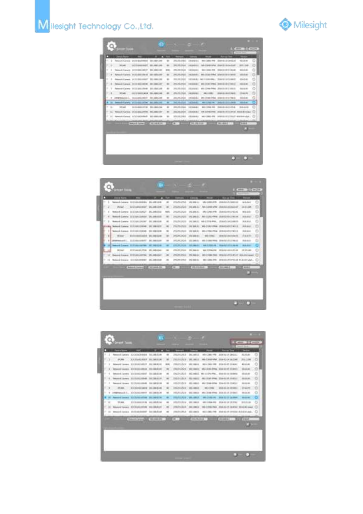
Step3: Select a camera or multiple cameras according to the MAC addresses;
Page 38
32
Figure 3-1-2 Select single camera
Figure 3-1-3 Select multiple cameras
Step4: Type the User Name and Password (if they are not the default value.);
Figure 3-1-4
Page 39
33
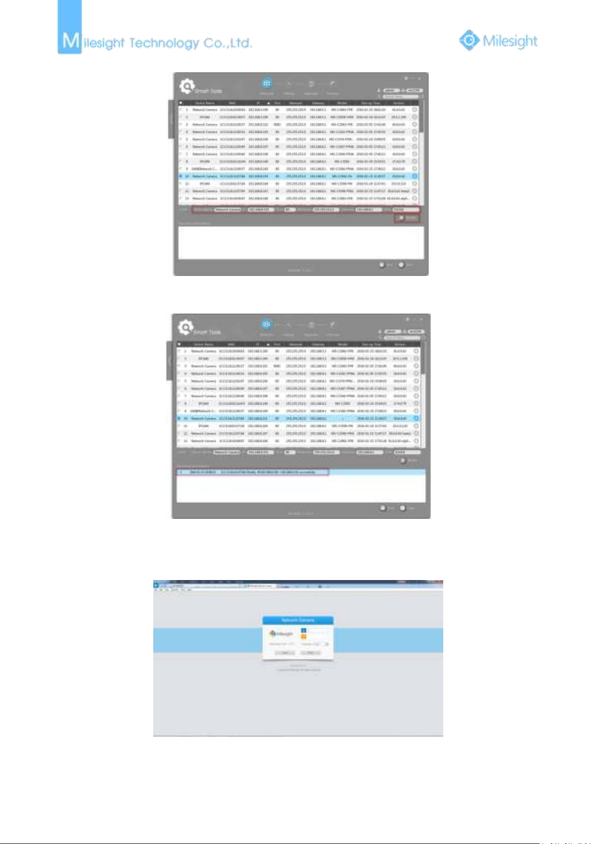
Step5: Change the IP address or other network values, and then click “Modify” button;
Figure 3-1-5
Step6: Change the IP address successfully;
Figure 3-1-6 Change IP address successfully
Step7: By clicking the browser icon, you can access the camera via web browser directly. The
Internet Explorer window will pop up.
Figure 3-1-7
More usage of Smart Tools, please refer to the Smart Tools User Manual.
Page 40
34
3.1.2 Assign An IP Address via Browser
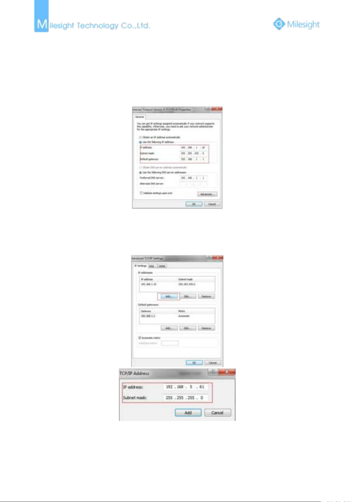
a. StartControl PanelNetwork and Internet ConnectionNetwork ConnectionLocal
b.Click “Advanced”, and then click “IP settings”“IP address”“Add” (See Figure 3-1-9).
If the network segment of the computer and that of the camera are different, please follow the
steps to change the IP address:
Step1: Change the IP address of computer to 192.168.5.0 segment, here are two ways as following:
Area Connection, and double click it. (Refer to Figure 3-1-8);
Figure 3-1-8
In the pop-up window, enter an IP address that in the same segment with Milesight
network camera ( e.g. 192.168.5.61, but please note that this IP address shall not conflict
with the IP address on the existing network);
Figure 3-1-9
Step2: Start the browser. In the address bar, enter the default IP address of the camera:
http://192.168.5.190;
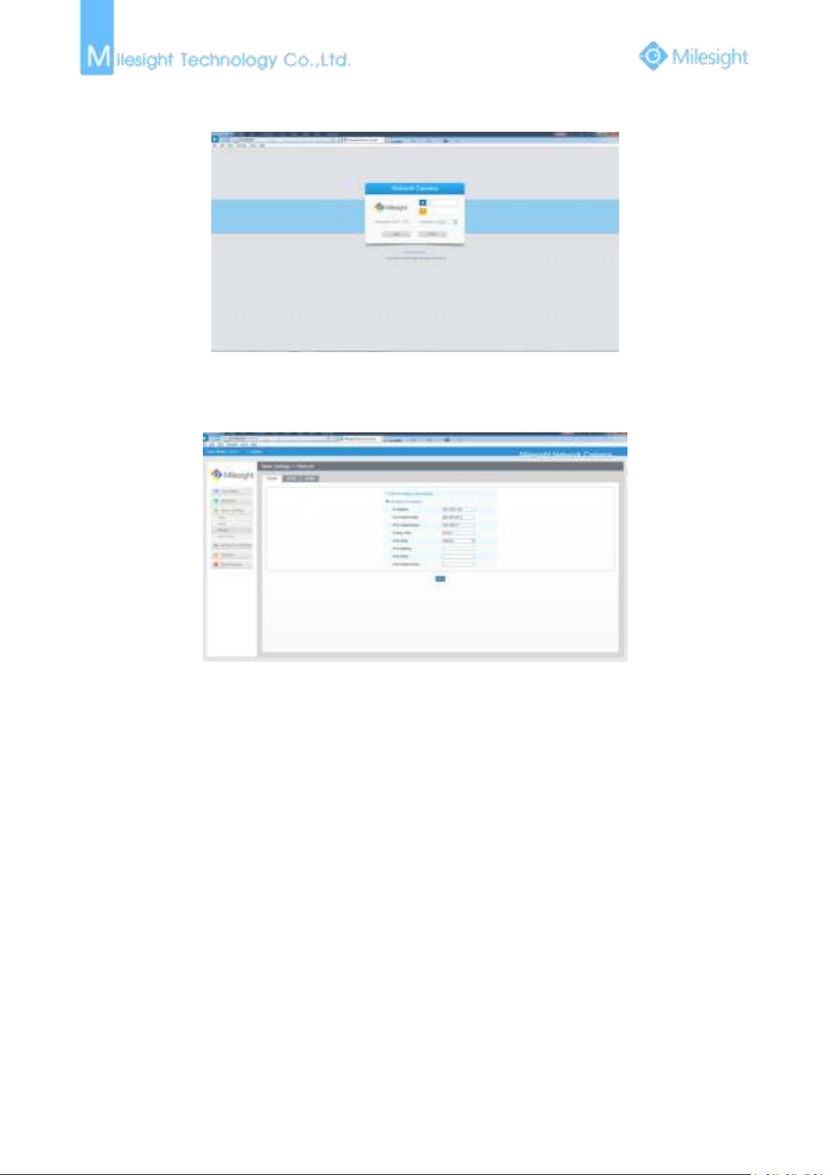
Step3: Enter the user name and password when the LOGIN page appears;
Page 41
35
Default user name: admin
Default password: ms1234
Figure 3-1-10
Step4: After login, please select “Configuration”“Basic Settings”“Network”“TCP/IP”. The
Network Settings page appears (Shown as following Figure);
Figure 3-1-11
Step5: Change the IP address or other network values. Then click “Save” button;
Step6: The change of default IP address is completed.
3.2 Accessing from the Web Browser
The camera can be used with the most standard operating systems and browsers. The
recommended browsers are Internet Explorer, Firefox, Chrome, Safari.
3.2.1 Access over IE Browser
Before using the browser to get access to your camera, you need to install the MsActiveX firstly.
You can refer the steps as follows:
Step1: Launch the IE browser and enter the IP address of the camera.
Step2: Enter the User Name and Password and click “Login”.
(The default user name is “admin”, password is “ms1234”)
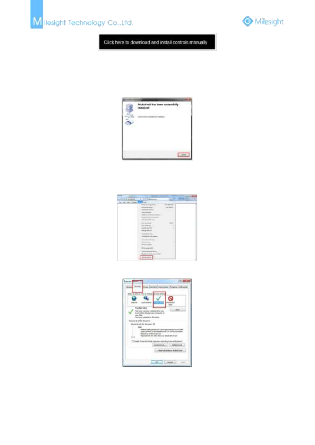
Step3: At the first time to log in the device, the browser will prompt to install Controls, please click
“Click here to download and install controls manually” as Figure 3-2-1.
Page 42
36
Figure 3-2-1
1)During installing the controls, please keep the browsers close.
Note:
Step4: Follow the prompts to install the Controls, when it`s finished, it will pop out a window as
Figure 3-2-2. Please click “Finish” and refresh the browser, then you will see the video.
Figure 3-2-2
If IE9 or higher version browser is used, it is suggested that the Milesight camera web link should
be added as a trusted site. See the instructions as follows:
Step1: Start the IE9 or higher version browser, and select “Tools”“Internet Options”;
Figure 3-2-3
Step2: Select “Security” to “Trusted”;
Figure 3-2-4
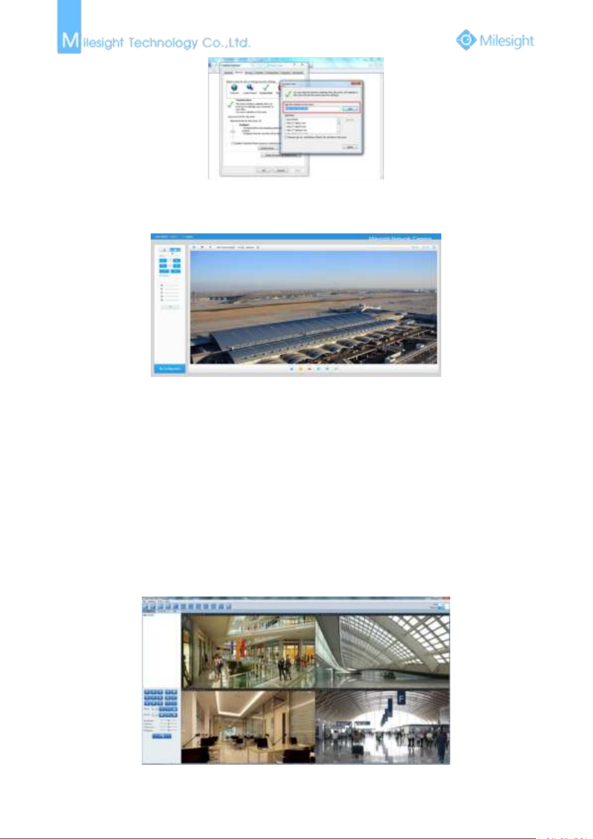
Step3: Enter the IP address of the camera in the blank and click “Add”;
Page 43
37
Figure 3-2-5
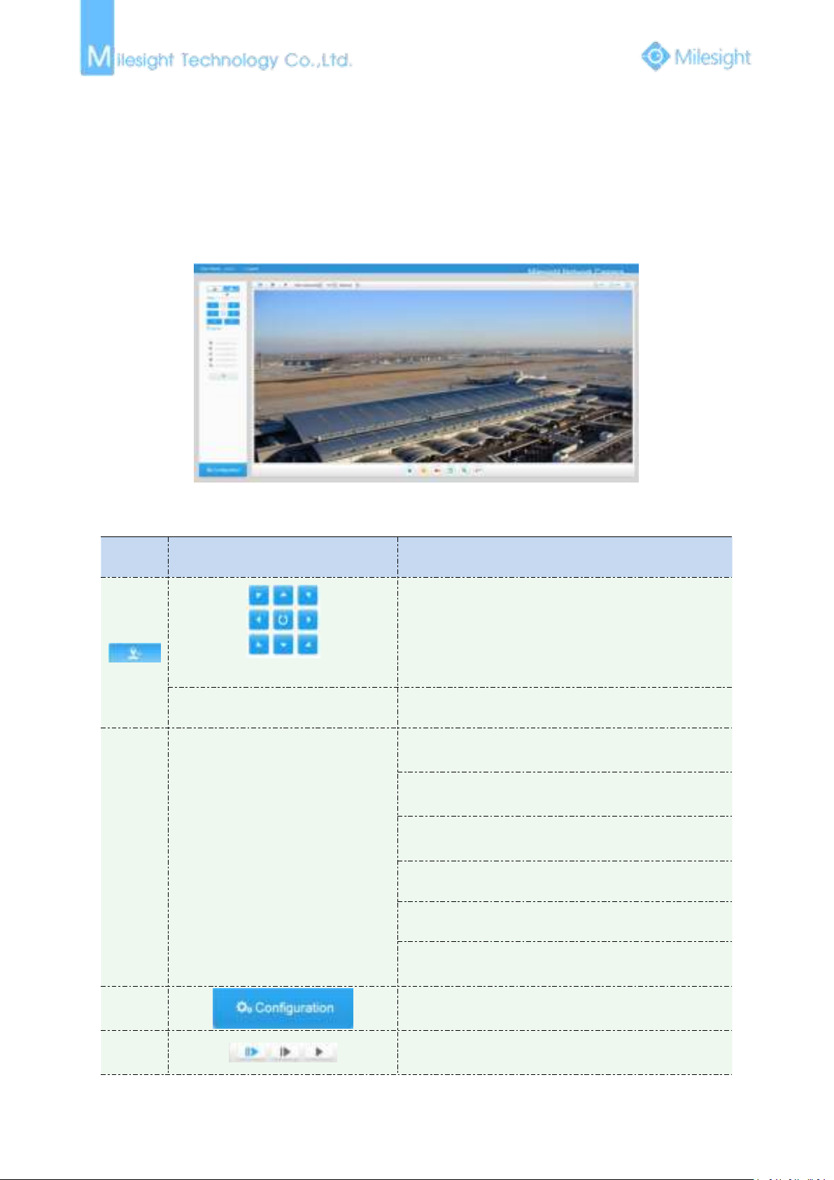
Step4: Enter the IP address. After logging on network camera’s web GUI successfully, user is
allowed to view live video as follows.
Figure 3-2-6
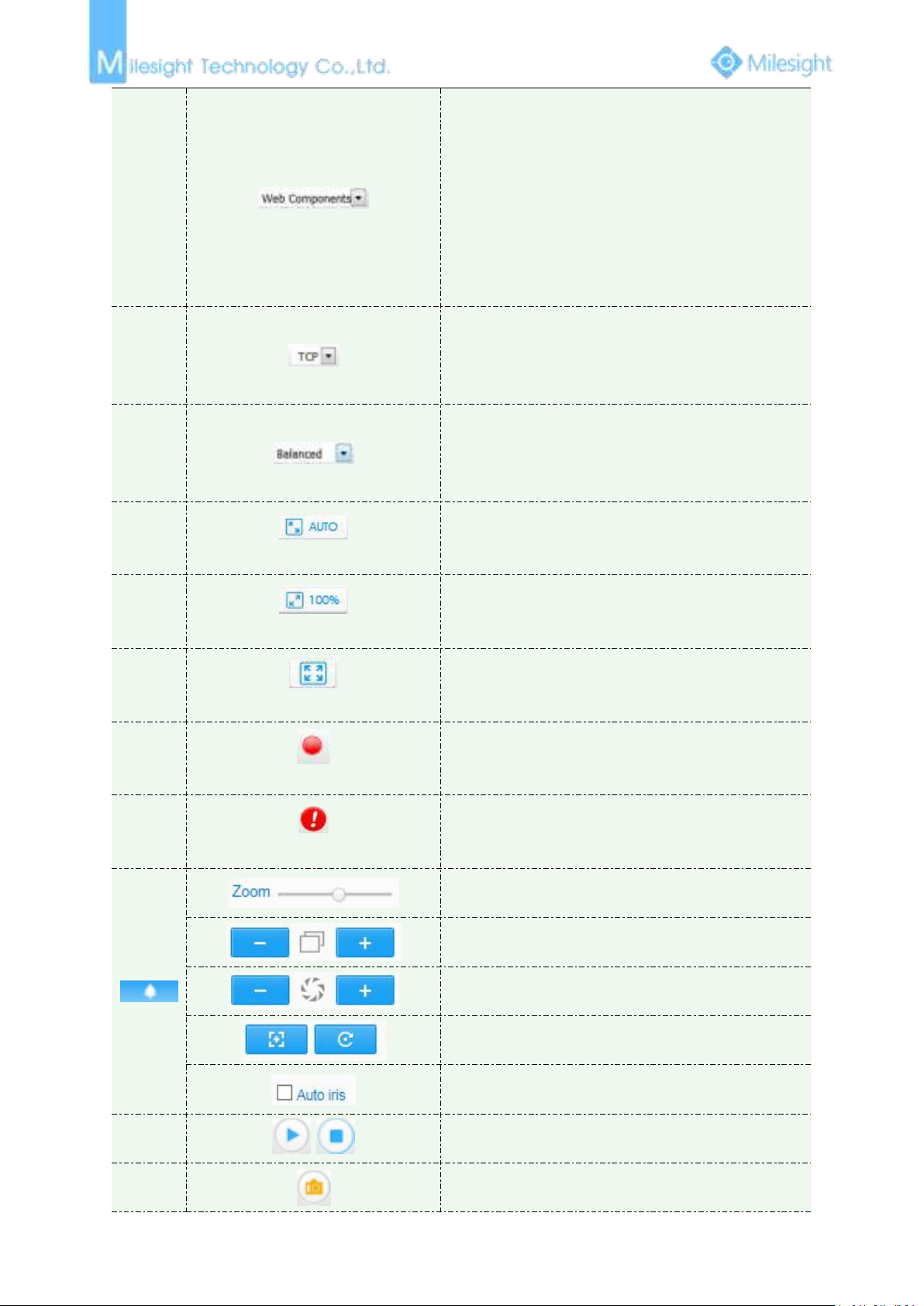
3.3 Accessing from Milesight VMS (Video Management Software)
Milesight VMS(ONVIF compatible) is a handy and reliable application designed to work with
network cameras in order to provide video surveillance, recording settings and event management
functions. The interface of Milesight VMS is very easy to use, intuitive, with easy access to the
most common activities, such as viewing live video, searching through recordings and exporting
videos and snapshots. It's able to be integrated with other devices through ONVIF. It is designed to
work on Windows XP/7/8/Vista/ Server 2000/ Server 2008. The software could be downloaded
from our website
Please install Milesight VMS; then launch the program to add the camera to the channel list. For
detailed information about how to use the software, please refer to user manual of Milesight VMS.
www.milesight.com.
Figure 3-3-1
Page 44
38
Chapter IV System Operation Guide
No.
Parameter
Description
PTZ Control
Navigation key is used to control the direction. The
rotation key is used for auto-rotation under the E-PTZ
mode
PTZ Speed
PTZ rotation speed control
2
Image Adjustment
Brightness: A brighter scene appears, if a higher level of
brightness is chosen
Contrast: The difference in color and light between
parts of an image
Saturation: A more vivid scene appears, if a higher level
of saturation is chose
Sharpness: Make image more sharp
Noise Reduction Level: Adjust the noise reduction level
Default Settings: Restore brightness, contrast and
saturation to default settings
3
Click to access the configuration page
4
Choose the Stream ( Primary/Secondary/Third ) to
show on the current video window
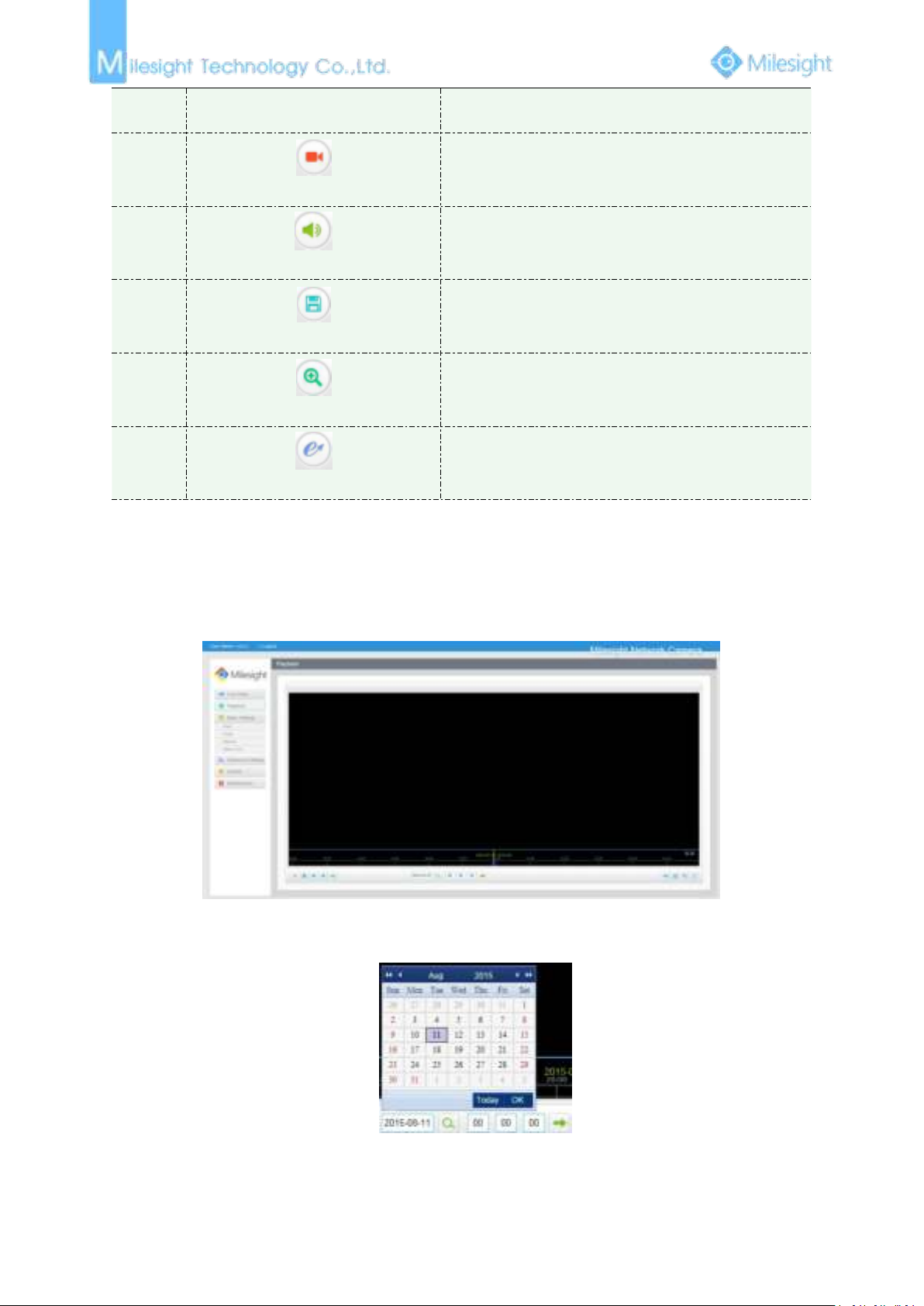
4.1 Live Video
After logging in the network camera web GUI successfully, user is allowed to view live video as
follows.
Figure 4-1-1 Live view interface
Table 4-1-1 Description of the buttons
Page 45
39
5
Only available for camera whose software version is
43 or above
Web Components: Support Firefox, Safari, Chrome
(Chrome version 44 or below); need to install the
component to display the view;
MJPEG: Support to display the view on Firefox, Safari,
Chrome (Chrome version 45 or above);
(
NOTE: IE choose Web Components mode for default, in
this case, it will not show the options)
6
TCP: More reliable connection;
UDP: More instantaneous connection, but if you cannot
get the live view successfully, please turn into TCP
connection;
7
Least Delay: Most instantaneous mode in the three
modes;
Balanced: Combine the fluent with timely characters;
Best Fluency: Most fluent mode in the three modes;
8
Window size
Click to display images at a window size
9
Real size
Click to display images at a real size
10
Full Screen
Click to display images at full-screen
11
Recording
When recording, the icon will turn red
12
Alarm
When an alarm causes recording, the icon will turn red
Adjust the Zoom length of the lens( Only work when
your camera is equipped with motorized lens)
Adjust focus of the lens(Only work when your camera is
equipped with motorized lens)
Adjust the size of IRIS(Only work when your camera is
equipped with motorized lens)
Auxiliary Focus and Lens Initialization(Only work when
your camera is equipped with motorized lens
)
Adjust iris automatically if check this box(Only work
when your camera is equipped with P-Iris
)
14
/
Start/Stop live view
15
Click to capture the current image and save to the
configured path. The default path is
Page 46
40
Capture
C:VMS\+-1\ IMAGE-MANUAL
16
Start Recording
Click to start recording video and save to the configured
path. The default path is C:VMS\+-1\MS_Record. Click
again to stop recording
17
Play Audio
Enable Audio Input/Output. It can also be set in Audio
configuration page
18
Saving Path Settings
Set the saving path for captured images and video
recordings of operating on the live view
19
Enable Zoom
When enabled, you can zoom in in a specific area of
video image with your mouse wheel
20
E-PTZ
Able to use PTZ to move the position
4.2 Playback
1) The date with bright red means there is recorded file in this day; one with dark red means
This section explains how to view the remotely recorded video files stored in SD cards.
Step1: Click [Playback] on the menu bar to enter playback interface.
Figure 4-2-1 Playback interface
Step2: Click the date button, choose the date when date window pops up;
Note:
Figure 4-2-2 Search Video
Page 47
41
weekend day; one with blue background means the date is selected now.
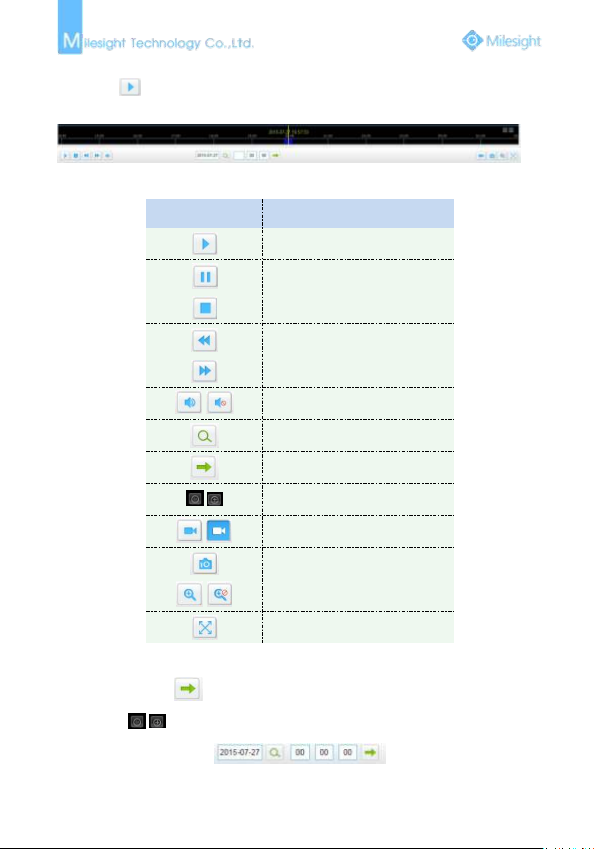
Button
Operation
Play
Pause
Stop
Slow Forward
Fast Forward
/
Audio On/Off
Search
Go To
/
Time Narrow/Expand
/
Start/Stop Recording
Snapshot
/
Zoom On/Off
Full Screen
1) Drag the progress bar with the mouse to locate the exact playback point. You can also input
Step3: Click
to play the video files found on this date.
The toolbar on the button of playback interface can be used to control playing progress.
Figure 4-2-3 Playback Toolbar
Table 4-1-2 Description of the buttons
Note:
the time and click to locate the playback point in the Set Playback Time filed. You can
also click
/ to zoom out/in the progress bar.
Figure 4-2-4 Set Payback Time
Page 48
42
4.3 Basic Settings
Parameters
Function Introduction
4.3.1 Video
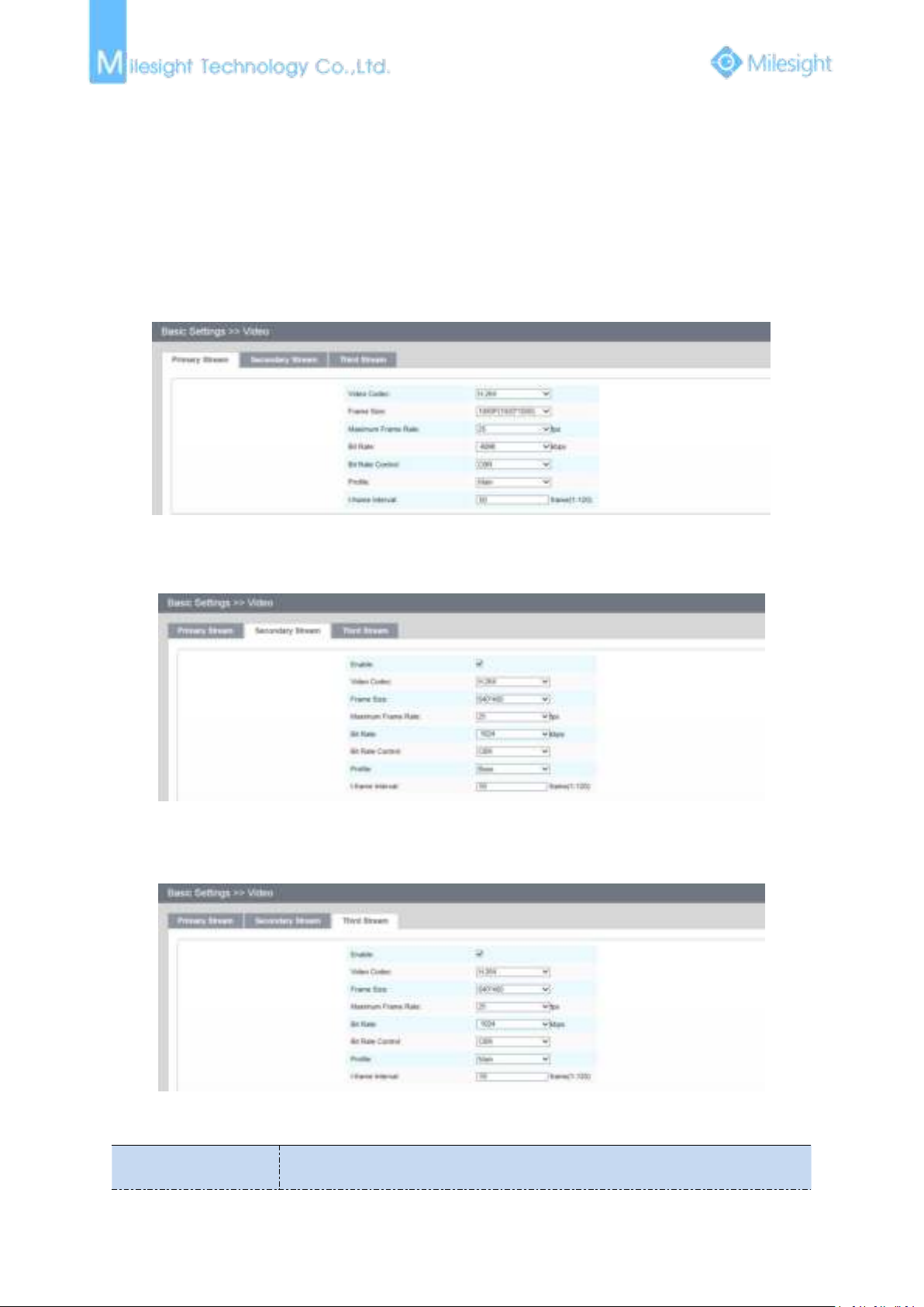
Stream parameters can be set in this module, adapting to different network environments and
demands.
Primary Stream Settings
Figure 4-3-1 Primary Stream Settings
Secondary Stream Settings
Third Stream Settings
Figure 4-3-2 Secondary Stream
Figure 4-3-3 Third Stream
Table 4-3-1 Description of the buttons
Page 49
43
Video Codec
There are difference for the camera with “-A” and “-B”
-A: H.264/MJPEG available
-B: H.265/H.264/MJPEG available
Frame Size
Options include 4M(2592*1520), 3M(2304*1296), 3M(2048*1536),
1080P(1920*1080), 2M(1600 *1200), 1.3M(1280*960), 720P(1280*720), D1
(704*576)
Maximum Frame Rate
Maximum refresh frame rate of per second
Bit Rate
Transmitting bits of data per second, this item is optional only if you select the
H.265/H.264
Bit Rate Control
CBR: Constant Bitrate. The rate of CBR output is constant
VBR: Variable Bitrate. VBR files vary the amount of output date per time
segment
Profile
The option is for H.264, Main/High can be selected according to your needs.
I-frame Interval
Set the I-frame interval to 1~120, 50 for the default. This item is optional only if
you select the H.265/H.264. The number must be a multiple of the number of
frames.
JPEG Quality
Low/Medium/High/Higher are available, this item is optional only if you select
the MJPEG
Note:
1) The options of [Frame Size] are variable according to the model selected.
4.3.2 Image
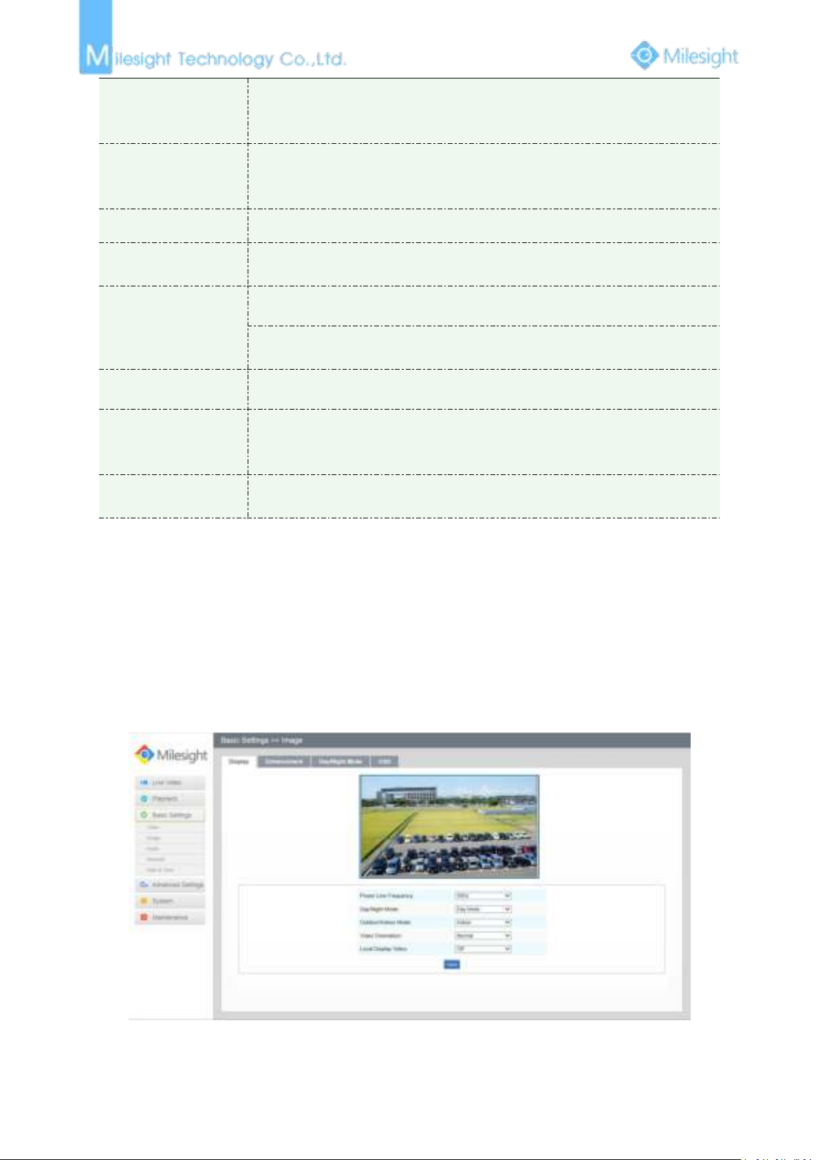
Display information, enhancement of image and Day/Night setting can be set in this module. OSD
(On Screen Display) content and video time can be displayed to rich the image information.
Display
Figure 4-3-4 Display
Page 50
44
Table 4-3-2 Description of the buttons
Parameters
Function Introduction
Power Line Frequency
60HZ flicker for NTSC mode and 50HZ flicker for PAL mode
Day/Night Mode
There are several parameters such as Exposure Level, Maximum Exposure Time
and IR-CUT Interval, etc, associated with this mode
Night Mode: Shown in live view based on Night Mode settings
Day Mode: Shown in live view based on Day Mode settings
Auto Mode: Shown in live view based on environment, set the sensitivity for
switching Day Mode to Night Mode, or Night Mode to Day Mode
Customize: Shown in live view based on your own settings’ time to start/end
Night Mode
Day To Night Value
This is the sensitivity for switching Day Mode to Night Mode. When IR Light
Sensor Current Value is lower than this value, it will switch Day Mode to Night
Mode
Night To Day Value
This is the sensitivity for switching Night Mode to Day Mode. When IR Light
Sensor Current Value is higher than this value, it will switch Night Mode to Day
Mode
IR Light Sensor Current
Value
The current value of the IR light sensor
Outdoor/Indoor Mode
Select indoor or outdoor mode to meet your needs
Video Orientation
There are six options available, you can select one to meet your need
Normal: Remain the image in normal direction
Flip Horizontal: Flip the image horizontally
Flip vertical: Flip the image vertically
Rotating 90°: The images is presented rotating 90°
Rotating 180°: The images is presented upside down
Rotating 270°: The images is presented rotating 270°
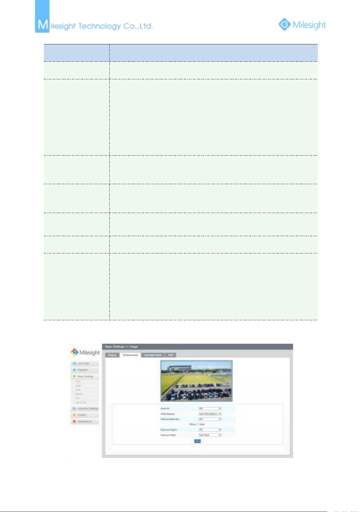
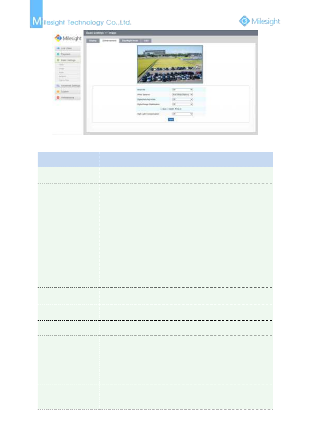
Enhancement
Figure 4-3-5 Enhancement (H.264 series)
Page 51
45
Figure 4-3-6 Enhancement (H.265 series)
Parameters
Function Introduction
Smart IR
There is an option to turn On/Off the IR LED. Select smart IR on, and the IR LED
changes according to the actual illumination.
White Balance
To restore white objects, removed color distortion because of the light of
the environment
Auto White Balance: This option will automatically enable the White Balance
function
Manual White Balance: This option is only for H.265 series, set Red Gain Level
and Blue Gain Level manually.
Incandescent Lamp: Select this option when light is similar with incandescent
lamp
Warm Light Lamp: Select this option when light is similar with warm light lamp
Natural Light: Select this option when there is no else light but natural light
Fluorescent Lamp: Select this option when light is similar with Fluorescent
Lamp
Reduce Motion Blur
This function is only for H.264 series, better image for moving objects, it may
lead worse quality for still objects
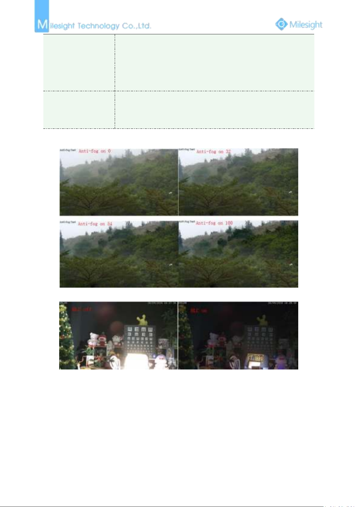
Digital Anti-fog Mode
This function is only for H.265 series, better image effect in foggy weather,
refers to Figure 4-3-7
Digital Image Stabilisation
This function is only for H.265 series, better image effect when image shaking
Exposure Region
(BLC)
Off, Customize, and Centre are available, only enable when WDR is disable
Off: Calculate the full range of view and offer appropriate light compensation
Customize: This option enables you to add customized windows as inclusive or
exclusive regions manually
Centre: This option will automatically add an inclusive region in the middle of
the window and give the necessary light compensation
Exposure Mode
(BLC)
Auto mode/Customize mode. If you choose customize mode, the camera
adjusts the brightness according to the value you set. The higher the value, the
brighter the image.
Table 4-3-3 Description of the buttons
Page 52
46
Wide Dynamic Range
(WDR)
This function enables the capture and display of both bright and dark areas in
the same frame, there are details in both areas in this way
Off: Disable WDR function
On: Enable the WDR, there are Low/High/Auto three levels
Customize: Customize the schedule to enable/disable the WDR function and
set the levels with Low/High/Auto
High Light Compensation
(HLC)
This function is only for H.265 series, adjust the brightness to a normal range
when the light is strong, refers to Figure 4-3-8
Off: Disable HLC function
On: Enable the HLC, and there is a setting for HLC Level
Figure 4-3-7 Anti-fog Image
Figure 4-3-8 HLC Image
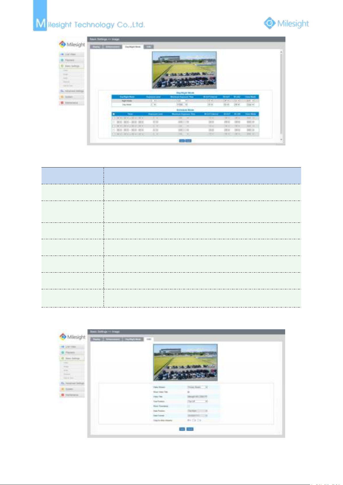
Day/Night Mode
Page 53
47
Parameters
Function Introduction
Exposure Level
Level 0~10 are available to meet your need
Maximum Exposure
Time
Set the maximum exposure time to 1/5~1/100000
IR-CUT Interval
The interval to keep the mode from switching
IR-CUT
Choose to turn on or turn off under this mode
IR LED
Choose to turn on or turn off under this mode
Color Mode
Select B/W or Color mode under Day/Night mode
Schedule Mode
Here you can customize your special demands for different time, then the Day
mode and Night mode will switch automatically according to your settings
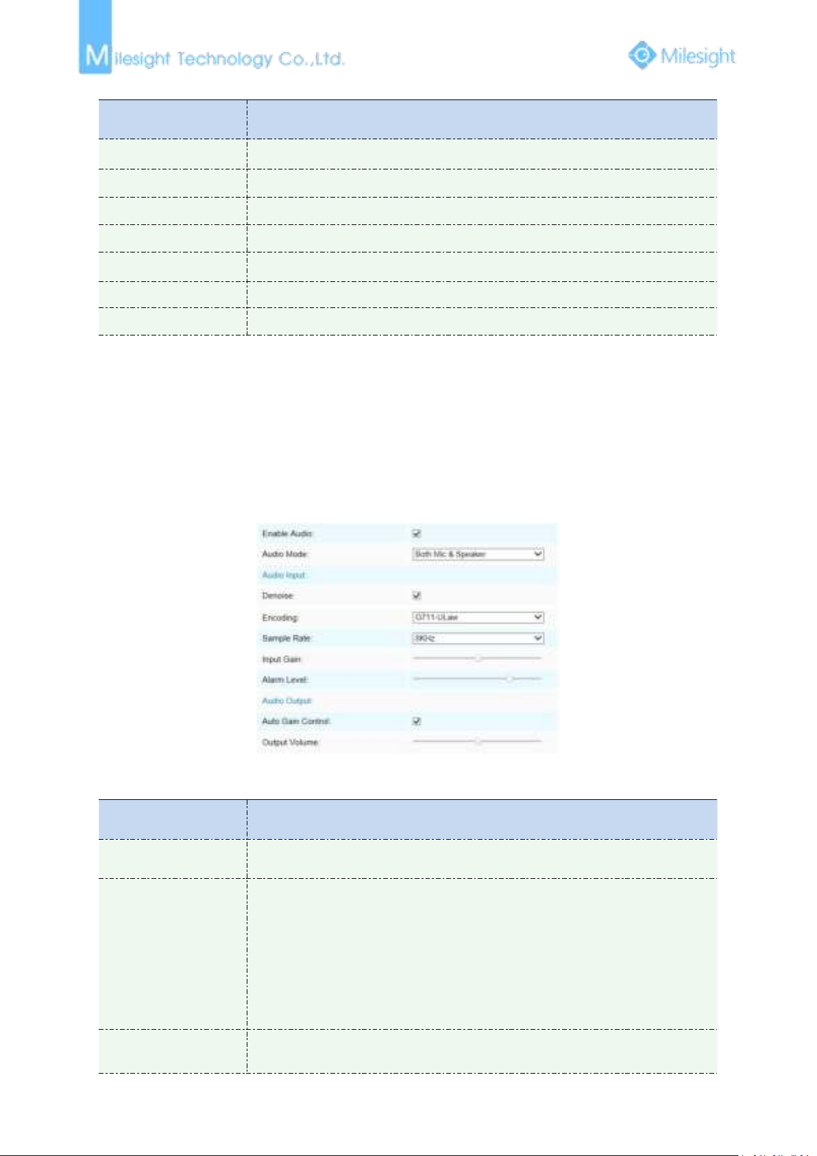
On Screen Display(OSD)
Figure 4-3-9 Day/Night Mode
Table 4-3-4 Description of the buttons
Figure 4-3-10 OSD
Page 54
48
Table 4-3-5 Description of the buttons
Parameters
Function Introduction
Show Video Title
Check the checkbox to show video title
Video Title
OSD content customized
Text Position
OSD display position on the image
Show Timestamp
Check the checkbox to display date on the image
Date Position
Date display position on the image
Date Format
The format of date
Copy to other streams
Copy the settings to other streams
Parameters
Function Introduction
Enable Audio
Check on the checkbox to enable audio feature
Audio Input
Denoise: Set it as On/Off. When you set the function on, the noise detected can
be filtered
Encoding: G711-ULaw, G711-ALaw and AAC LC are available
Sample Rate: There are 8KHz/16KHz two options
Input Gain: Input audio gain level, 0-100
Alarm Level: Alarm will be triggered if voice alarm is enabled and input gained
volume is higher than the alarm level, 0-100
Audio Output
Auto Gain Control: This function is only for H.265 series, improve the quality of
audio
4.3.3 Audio
This audio function allows you to hear the sound from the camera or transmit your sound to the
camera side. A two-way communication is also possible to be achieved with this feature. Alarm can
be triggered when the audio input is above a certain alarm level you set, and configured audio can
be played when an alarm occurs.
Figure 4-3-11 Audio
Table 4-3-6 Description of the buttons
Page 55
49
Output Volume: Adjust volume of output
Note:
1) The Audio mode and Audio Output are only for certain modules.
Parameters
Function Introduction
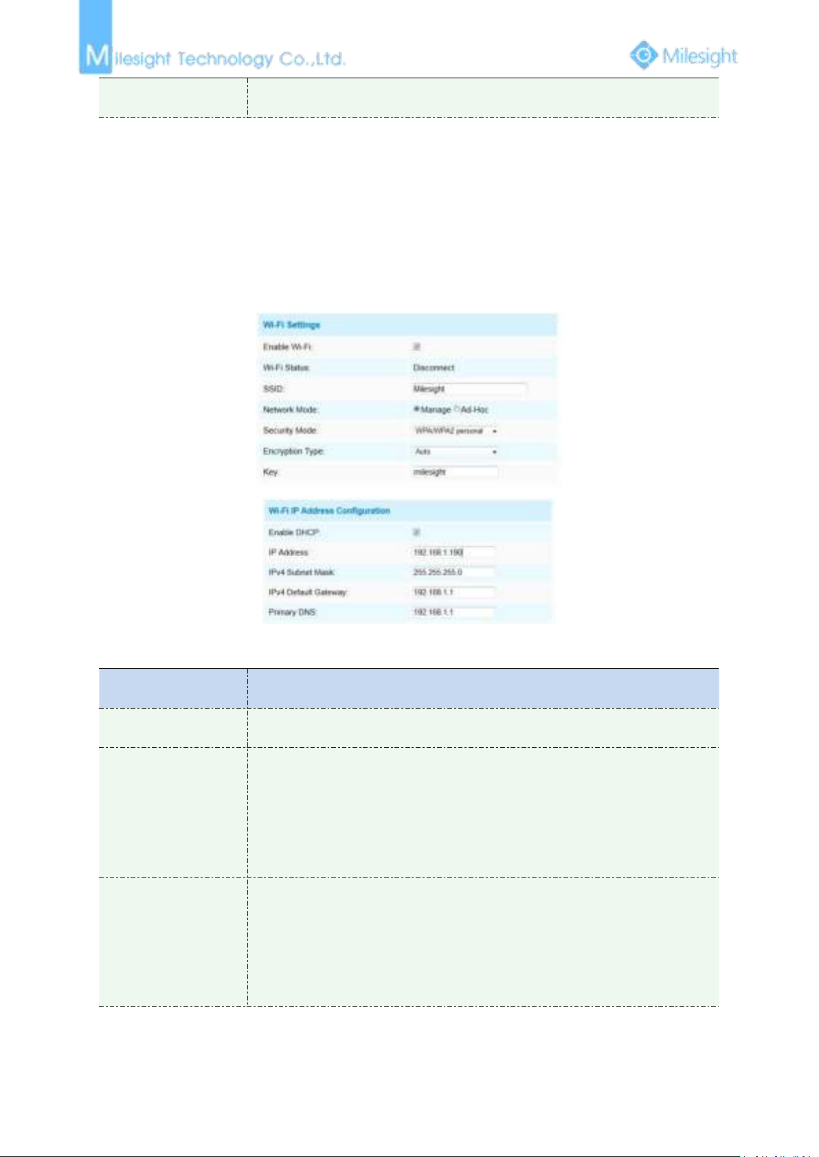
Enable Wi-Fi
Enable/Disable the Wi-Fi function
Wi-Fi Settings
Wi-Fi Status: Connected/Disconnected
SSID: Wi-Fi source
Network Mode: Wi-Fi option for Manage and Ad-Hoc mode
Security Mode: Select Wi-Fi connection security mode
Encryption Type: Auto/TKIP/AES are available
Key: Enter the Key of Wi-Fi to connect
Wi-Fi IP Address
Configuration
Enable DHCP: Check the checkbox to enable the DHCP function
IPv4 Address: Address used to identify a network camera on the network
IPv4 Subnet Mask: It is used to identify the subnet where the network camera is
located
IPv4 Default Gateway: The default gateway address
Primary DNS: The DNS Server translates the domain name to IP address
4.3.4 Wi-Fi
Wi-Fi
The page is as follows:
Figure 4-3-12 Wi-Fi
Table 4-3-7 Description of the buttons
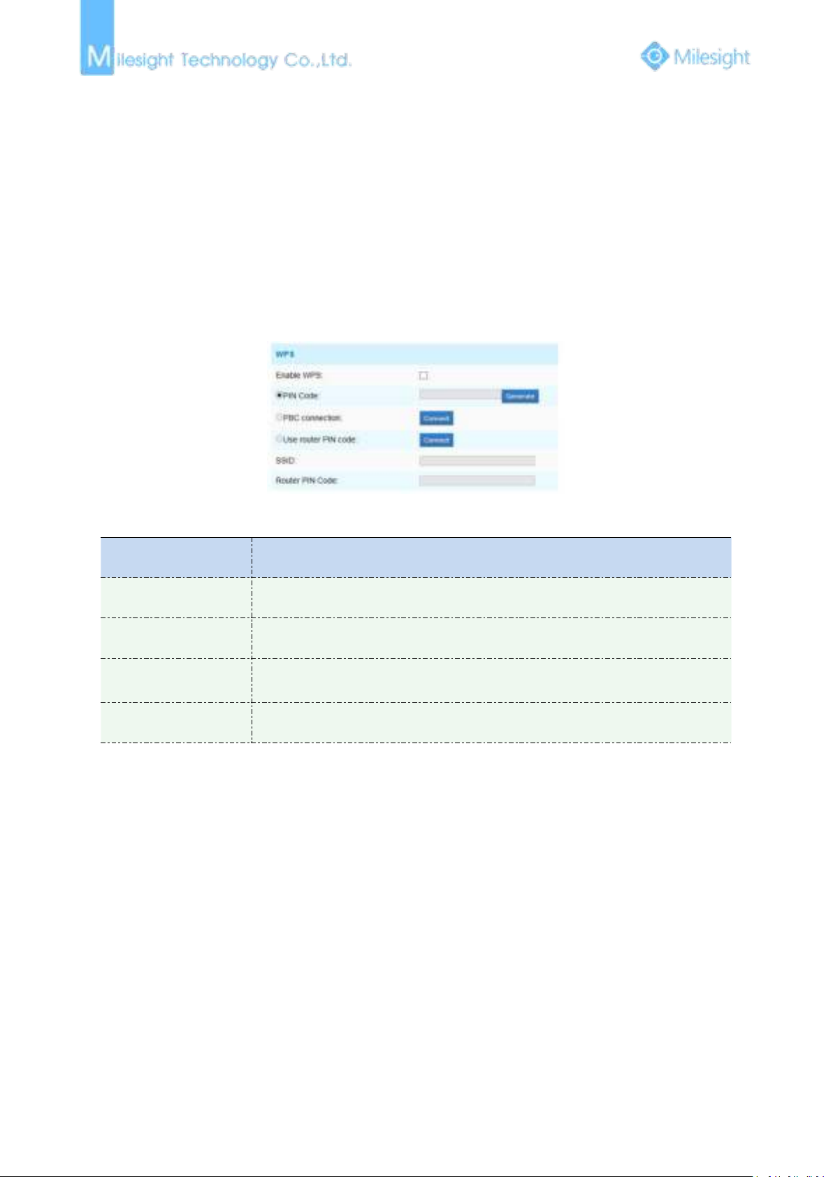
WPS(Wi-Fi Protected Setup)
Originally Wi-Fi Simple Config, it’s a network security standard that allows users to easily secure a
Page 56
50
wireless home network. The goal of the protocol is to allow home users who know little of wireless
Parameters
Function Introduction
Enable WPS
Enable or Disable WPS
PIN Code
Click on the “Generate” to get a code, you need to add this PIN code to the router
PBC Connecting
Connect via PBC button, click on the PBC button on the router, then click
“Connect” button again
Use Router PIN Code
Enter the router PIN code here, and also with the SSID
1) Wi-Fi function is only applicable for Cube cameras if purchased, WPS need supports from Wi-Fi
2) If you use Fixed IP, please set IP the same segment with Wi-Fi router.
security and may be intimidated by the available security options to set up Wi-Fi Protected Access,
as well as making it easy to add new devices to an existing network without entering long
password phrases.
PIN Method
It’s a personal identification number (PIN) has to be read from either a sticker or the display on the
new wireless device. You can add the PIN code to the router or you add the Router PIN code on
this camera.
Push-Button Method
The user simply has to push a button, either an actual or virtual one, on both the access point and
the new wireless client device. Support of this mode is mandatory for access points and optional
for connecting devices.
Note:
router.
4.3.5 Network
Figure 4-3-13 WPS
Table 4-3-8 Description of the buttons
TCP/IP
Page 57
51
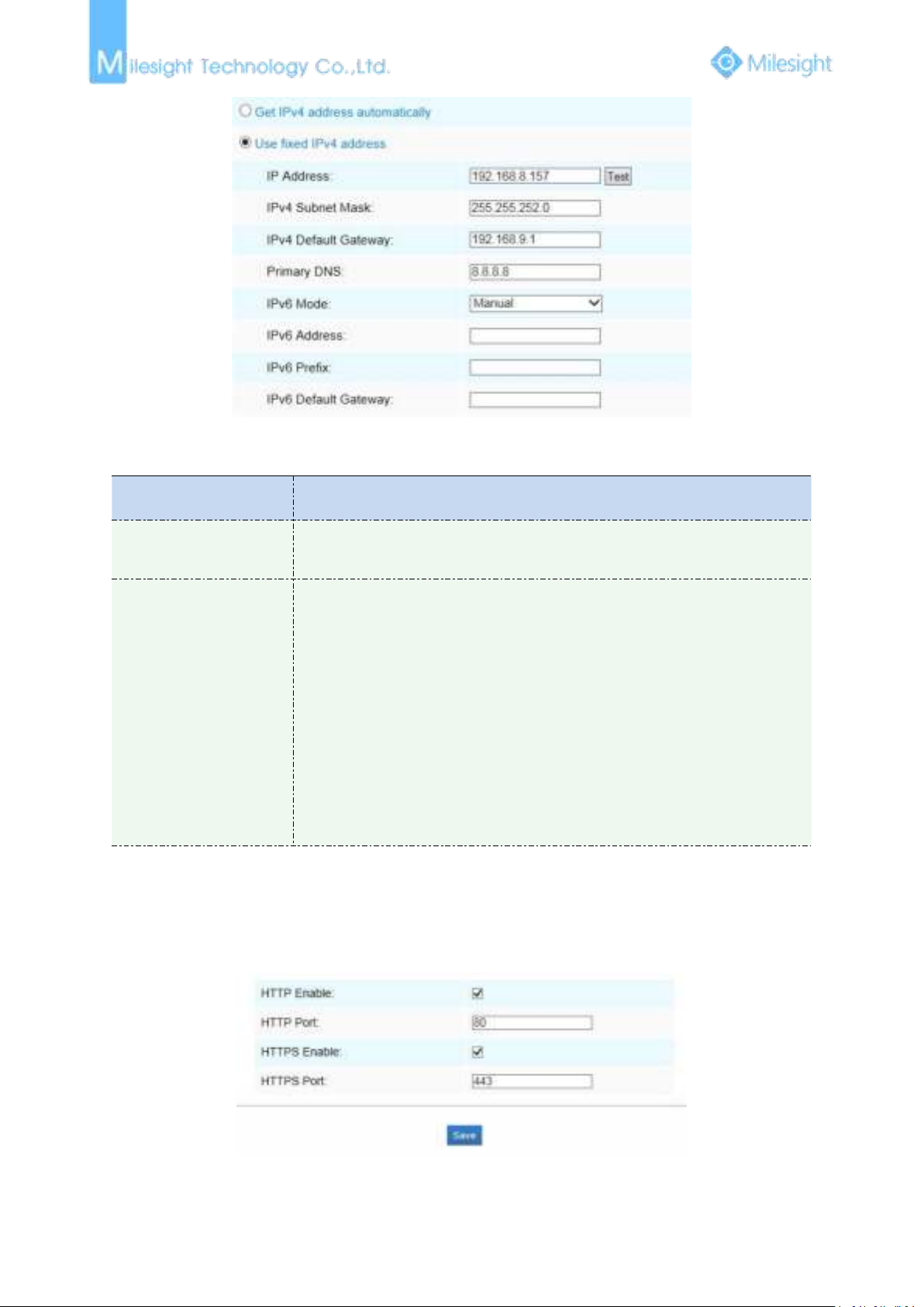
Parameters
Function Introduction
Get IPv4 Address
Automatically
Get an IP address from the DHCP server automatically
Use fixed IP address
IPv4 Address: An address that used to identify a network camera on the
network
IPv4 Subnet Mask: It is used for identifying the subnet where the network
camera is located
IPv4 Default Router: The default router address
Primary DNS: The DNS Server translates the domain name to IP address
IPv6 Mode: Choose different mode for IPv6: Manual/Route Advertisement/
DHCPv6
IPv6 Address: IPv6 Address used to identify a network camera on the network
IPv6 Prefix: Define the prefix length of IPv6 address
IPv6 Default Router: The default router IPv6 address
Note:
1) The Test button is used to test if the IP is conflicting.
Figure 4-3-14 TCP/IP
Table 4-3-9 Description of the buttons
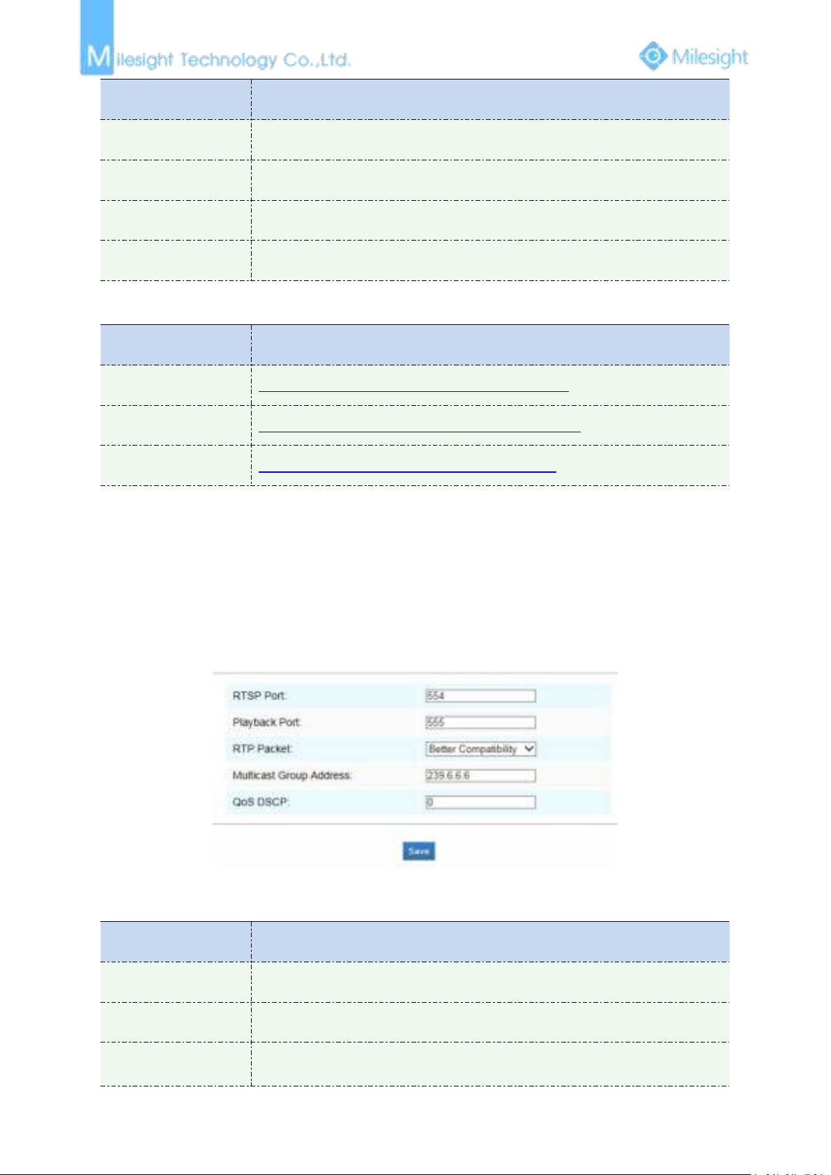
HTTP
Table 4-3-10 Description of the buttons
Figure 4-3-15 HTTP
Page 58
52
Parameters
Function Introduction
HTTP Enable
Start or stop using HTTP
HTTP Port
Web GUI login port, the default is 80, the same with ONVIF port
HTTPS Enable
Start or stop using HTTPS
HTTPS Port
Web GUI login port via HTTPS, the default is 443
HTTP URL are as following:
Stream
URL
Main Steam
http://username:password@IP:port/ipcam/mjpeg.cgi
Secondary Stream
http://username:password@IP:port/ipcam/mjpegcif.cgi
Third Stream
http://username:password@IP:port/mjpegthird.cgi
1) You need to change the codec type of streams to MJPEG expect the main stream of H.264
Parameters
Function Introduction
RTSP Port
The port of RTSP, the default is 554
Playback Port
The port of playback, the default is 555
RTP Packet
There are Better Compatibility and Better Performance two options, if your
camera’s image mess up, please switch this option
Note:
cameras whose models with “-A”.
RTSP
Figure 4-3-16 RTSP
Table 4-3-11 Description of the buttons
Page 59
53
Multicast Group
Address
Support multicast function
QoS DSCP
The valid value range of the DSCP is 0-63.
RTSP URL are as following:
Stream
URL
Main Steam
rtsp://username:password@IP:port/main
Secondary Stream
rtsp://username:password@IP:port/sub
Third Stream
http://username:password@IP:port/third
1) DSCP refers to the Differentiated Service Code Point; and the DSCP value is used in the IP
2) A reboot is required for the settings to take effect.
3) The third stream is only equipped on camera whose model with “-A” or “-B”.
Note:
header to indicate the priority of the data.
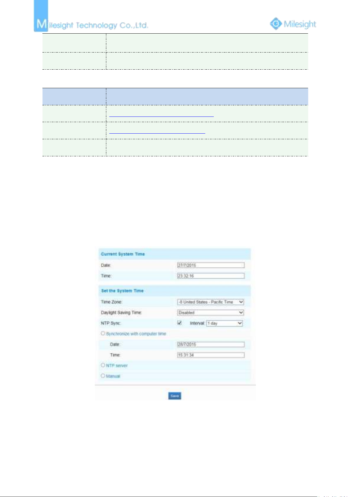
4.3.6 Date&Time
Current System Time
Current date&time of the system
Set the System Time
Figure 4-3-17 Date&Time
Page 60
54
Parameters
Function Introduction
Time Zone
Choose a time zone for your location
Daylight Saving time
Enable the daylight saving time
NTP Sync
Regularly update your time according to the interval time
Synchronize with
computer time
Synchronize the time with your computer
NTP server
Input the address of NTP server
Encryption Type
Synchronize the time with configured SNTP server and selected time zone
Manual
Set the system time manually
4.4 Advanced Settings
Parameters
Function Introduction
Enable
Check the checkbox to enable the Privacy Mask function
Clear All
Clear all areas you drew before
Table 4-3-12 Description of the buttons
4.4.1 Image
There are two more modules(Privacy Mask and ROI) in Advanced Settings than those in Basic
Settings. The same parts will not repeat again. Please refer to 4.3.2 if you are in need.
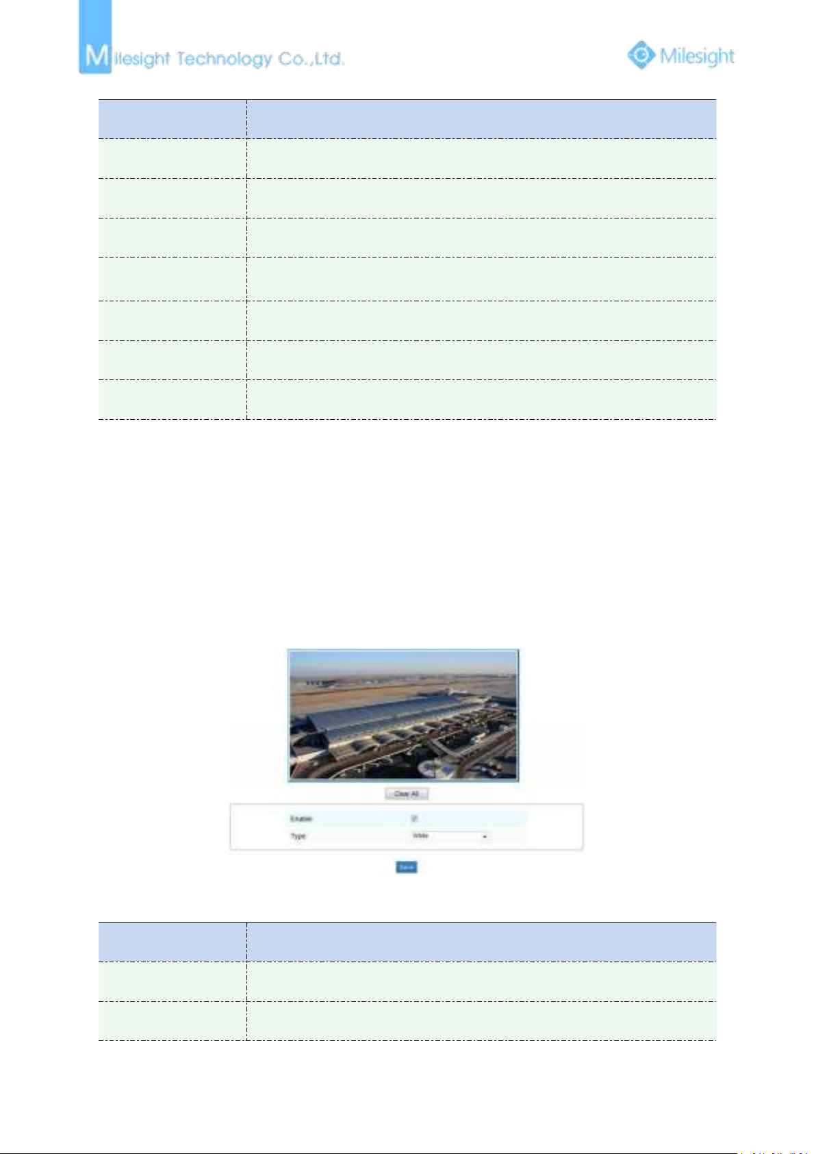
Privacy Mask
Figure 4-4-1 Privacy Mask
Table 4-4-1 Description of the buttons
Page 61
55
Type
Select the color to use for the privacy areas, there are three colors available:
White, Black, Blue
ROI
Parameters
Function Introduction
Enable
Check the checkbox to enable the ROI function
Clear All
Clear all areas you drew before
Video Stream
Choose the Video Stream
1) You can set a low bit rate.
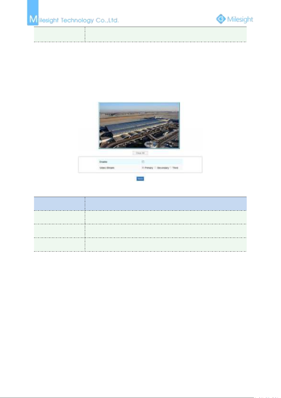
A region of interest(often abbreviated ROI), is a selected subset of samples within a dataset
identified for a particular purpose. Users can select up to 3 key regions of a scene to transmit as
separate streams for targeted preview and recording.
By using Milesight ROI technology, more than 50% of bit rate can be saved and therefore less
bandwidth demanded and the storage usage reduced. So according to this, you can set a small bit
rate for high resolution.
Figure 4-4-2 ROI
Table 4-4-2 Description of the buttons
Note:
4.4.2 Network
There are more several modules in Advanced Settings than those in Basic Settings. The same parts
will not repeat again. Please refer to 4.3.2 if you are in need.
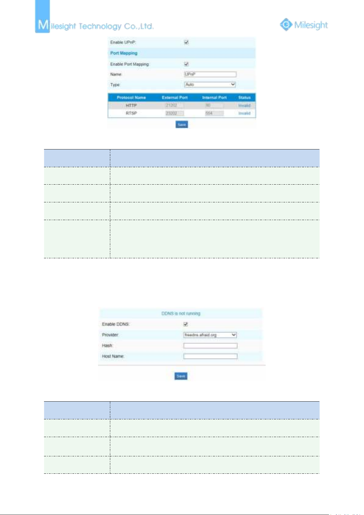
UPnP
Universal Plug and Play (UPnP) is a networking architecture that provides compatibility among
networking equipment, software and other hardware devices.The UPnP protocol allows devices to
connect seamlessly and to simplify the implementation of networks in the home and corporate
environments. With the function enabled, you don’t need to configure the port mapping for each
port, and the camera is connected to the Wide Area Network via the router.
Page 62
56
Figure 4-4-3 UPnP
Parameters
Function Introduction
Enable
Check the checkbox to enable the UPnP function
Enable Port Mapping
Check the checkbox to enable the Port Mapping
Name
The name of the device detected online can be edited
Type
Auto: Automatically obtain the corresponding HTTP and RTSP port, without any
settings
Manual: Need to manually set the appropriate HTTP port and RTSP Port. When
choose Manual, you can customize the value of the port number by yourself
Parameters
Function Introduction
Enable DDNS
Check the checkbox to enable DDNS service
Provider
Support DDNS from now dyndns.org, freedns.afraid.org, www.no-ip.com,
www.zoneedit.com
Hash
A string used for verifying, only for "freedns.afraid.org"
Table 4-4-3 Description of the buttons
DDNS
DDNS allows you to access the camera via domain names instead of IP address. It manages to
change IP address and update your domain information dynamically. You need to register an
account from a provider.
Figure 4-4-4 DDNS
Table 4-4-4 Description of the buttons
Page 63
57
User name
Account name from the DDNS provider, unavailable for "freedns.afraid.org"
Password
Account password, unavailable for "freedns.afraid.org"
Host name
DDNS name enabled in the account
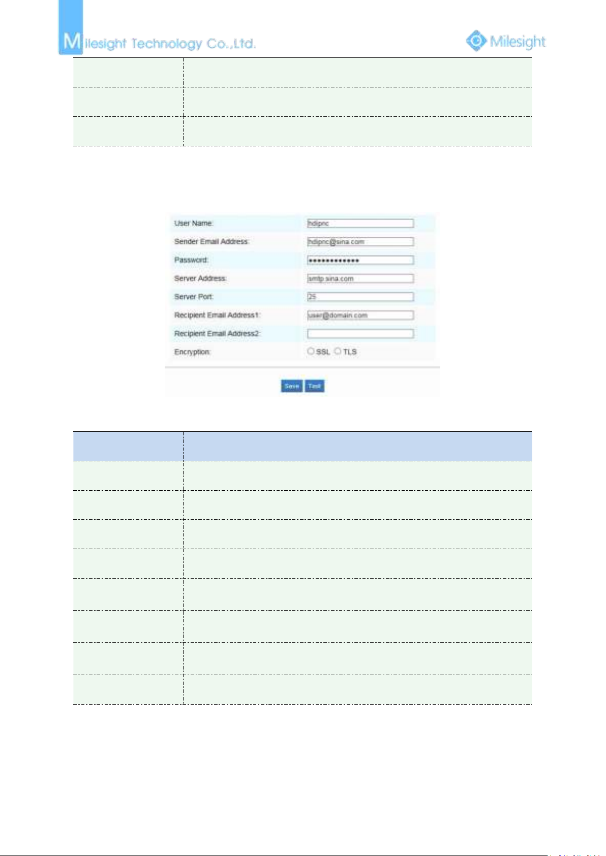
SMTP
Parameters
Function Introduction
User Name
The sender's name. It is usually the same as the account name
Sender Email Address
Email address to send video files attached emails
Password
The password of the sender
Server Address
The SMTP server IP address or host name(e.g. smtp.gmail.com)
Server Port
The port of SMTP server. The default TCP/IP port for SMTP is 25(not secured). For
SSL/TLS port, it depends on the mail you use
Recipient Email
Address1
Email address to receive video files
Recipient Email
Address2
Email address to receive video files
Encryption
Check the checkbox to enable SSL or TLS if it is required by the SMTP server.
Alarm video files can be sent to specific mail account through SMTP server. You must configure the
SMTP settings correctly before using it.
Figure 4-4-5 SMTP
Table 4-4-5 Description of the buttons
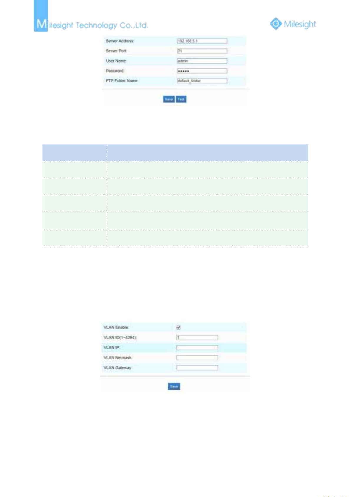
FTP
Alarm video files can be sent to specific FTP server. You must configure the FTP settings correctly
before using it.
Page 64
58
Figure 4-4-6 FTP
Parameters
Function Introduction
Server Address
FTP server address
Server Port
The port of the FTP server. Generally it is 21
User Name
User name used to log in to the FTP sever
Password
User password
FTP Folder Name
Path where video will be uploaded to on the FTP server
1) How to set up VLAN in switches, please refers to your switches user manual.
Table 4-4-6 Description of the buttons
VLAN
A virtual LAN (VLAN) is any broadcast domain that is partitioned and isolated in a computer
network at the data link layer (OSI layer 2). LAN is an abbreviation of local area network. VLANs
allow network administrators to group hosts together even if the hosts are not on the same
network switch. This can greatly simplify network design and deployment, because VLAN
membership can be configured through software. Without VLANs, grouping hosts according to
their resource needs necessitates the labour of relocating nodes or rewiring data links.
Note:
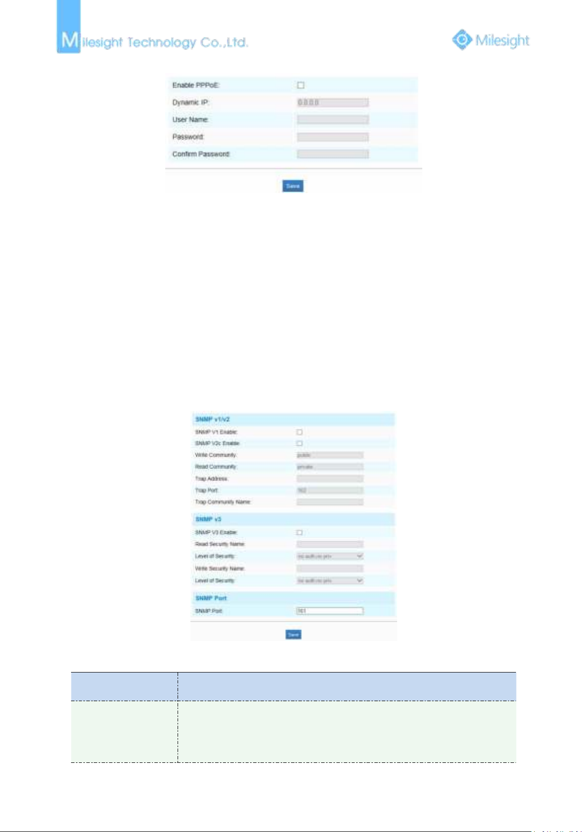
PPPoE
This camera supports the PPPoE auto dial-up function. The camera gets a public IP address by ADSL
dial-up after the camera is connected to a modem. You need to configure the PPPoE parameters of
Figure 4-4-7 VLAN
Page 65
59
the network camera.
1) The obtained IP address is dynamically assigned via PPPoE, so the IP address always changes
2) The user name and password should be assigned by your ISP.
Parameters
Function Introduction
SNMP v1/2/3
The version of SNMP, please select the version of your SNMP software.
SNMP v1: Provide no security
SNMP v2: Require password for access
SNMP v3: Provide encrytion and the HTTPS protocol must be enabled
Figure 4-4-8 PPPoE
Note:
after rebooting the camera. To solve the inconvenience of the dynamic IP, you need to get a
domain name from the DDNS provider (e.g. DynDns.com).
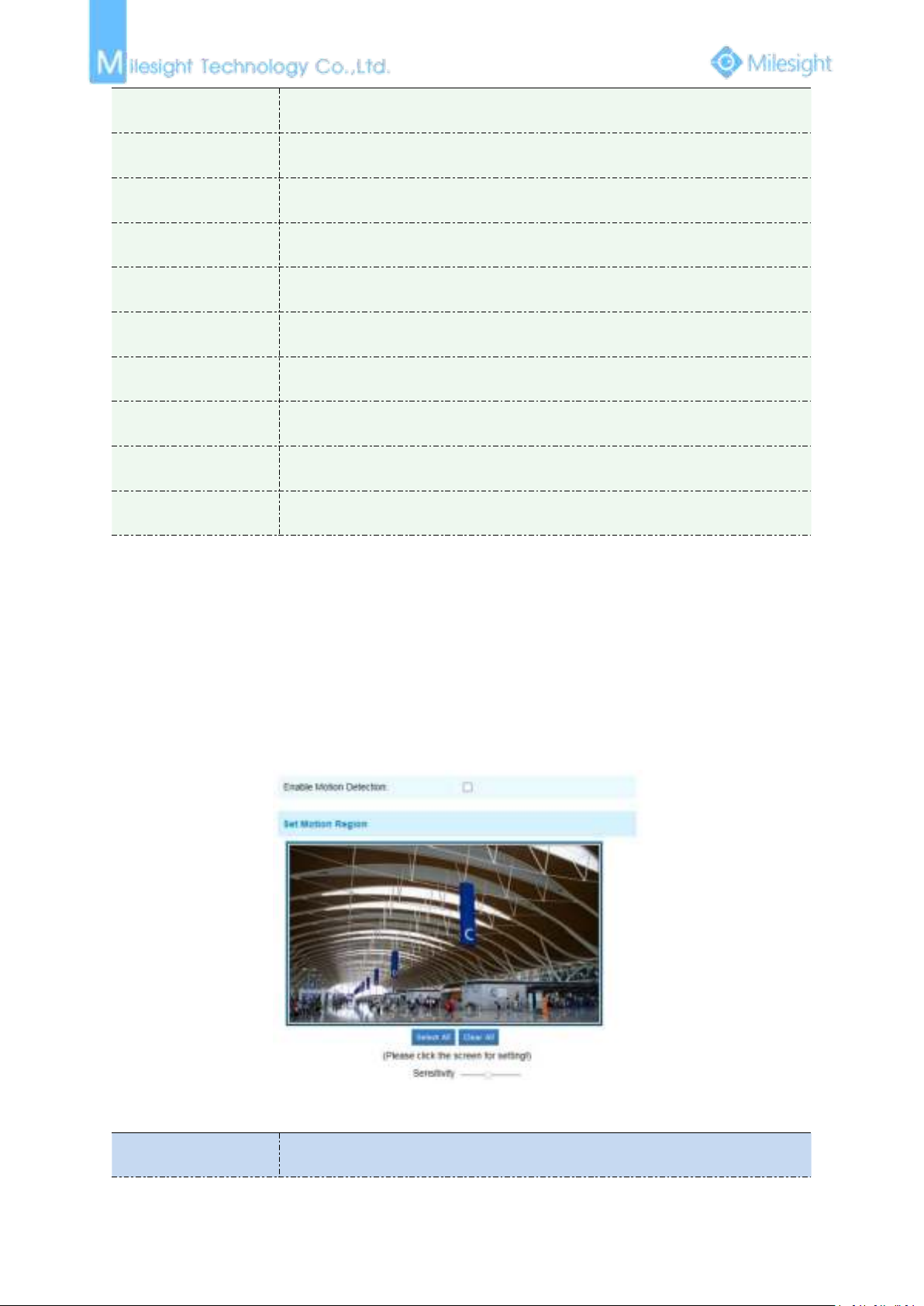
SNMP
You can set the SNMP function to get camera status, parameters and alarm related information
and manage the camera remotely when it is connected to the network.
Before setting the SNMP, please download the SNMP software and manage to receive the camera
information via SNMP port. By setting the Trap Address, the camera can send the alarm event and
exception messages to the surveillance center.
Figure 4-4-9 SNMP
Table 4-4-7 Description of the buttons
Page 66
60
Write Community
Input the name of Write Community
Read Community
Input the name of Read Community
Trap Address
Set the trap address
Trap Port
Set the trap port, the default is 162
Trap Community Name
Input the trap community name
Read Security Name
Input the name of Read Security Community
Level of Security
There are three levels available: (auth, priv), (auth, no priv) and (no auth, no priv)
Write Security Name
Input the name of Write Security Community
Level of Security
There are three levels available: (auth, priv), (auth, no priv) and (no auth, no priv)
SNMP Port
The port of SNMP, the default is 161
Note:
1) The settings of SNMP software should be the same as the settings you configure here;
2) A reboot is required for the settings to take effect.
Parameters
Function Introduction
4.4.3 Alarm
Motion Detection
Step1: Set motion region;
Figure 4-4-10 Motion Region
Table 4-4-7 Description of the buttons
Page 67
61
Enable Motion
Detection
Check the checkbox to enable Motion Detection function
Select All
Click the button, the motion in the area will be detected
Clear All
Click the button, the area drawn before will be removed
Sensitivity
Sensitivity level, 1~10
Step2: Set motion detection schedule;
Parameters
Function Introduction
Save Into SD Card
Save alarm recording files into SD Card
Save Into NAS
Save alarm recording files into NAS
Upload Via FTP
Upload the recording files via FTP
Upload Via SMTP
Upload the files via SMTP
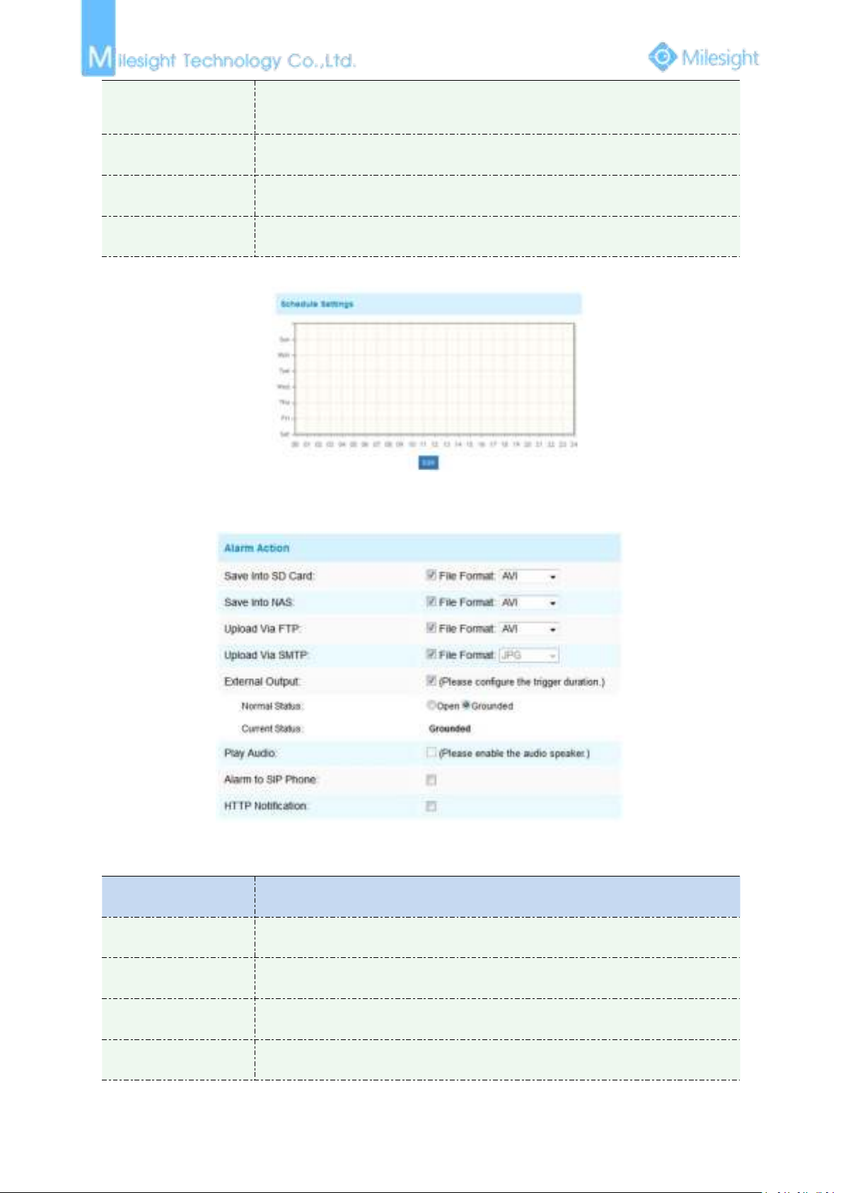
Step3: Set alarm action;
Figure 4-4-11 Schedule Settings
Figure 4-4-12 Alarm Action
Table 4-4-8 Description of the buttons
Page 68
62
External Output
If the camera equips with External Output, you can enable the action after
configuring the trigger duration
Play Audio
If the camera equips with Speaker, you can enable the action after configuring the
audio speaker
Play Buzzer
If the camera equips with Buzzer, you can check the checkbox to enable the
function.
Alarm to SIP Phone
Support to call the SIP phone after enable the SIP function.
HTTP Notification
Support to pop up the alarm news to specified HTTP URL.
NOTE:
1) The HTTP notification function is just one way for camera to send messages to VMS Software.
And it's the VMS that defines what the messages mean and decides what to do after receiving
this kind of messages. So, we can use the HTTP Notification function of our cameras only if the
VMS supports this kind of message format.
Here will take the Digifort as an example to introduce the HTTP Notification function.
The following are the detail steps of setting for HTTP Notification in Digifort VMS and our
cameras.
Step1: Enable Alarm, set Motion Region and detection Schedule.
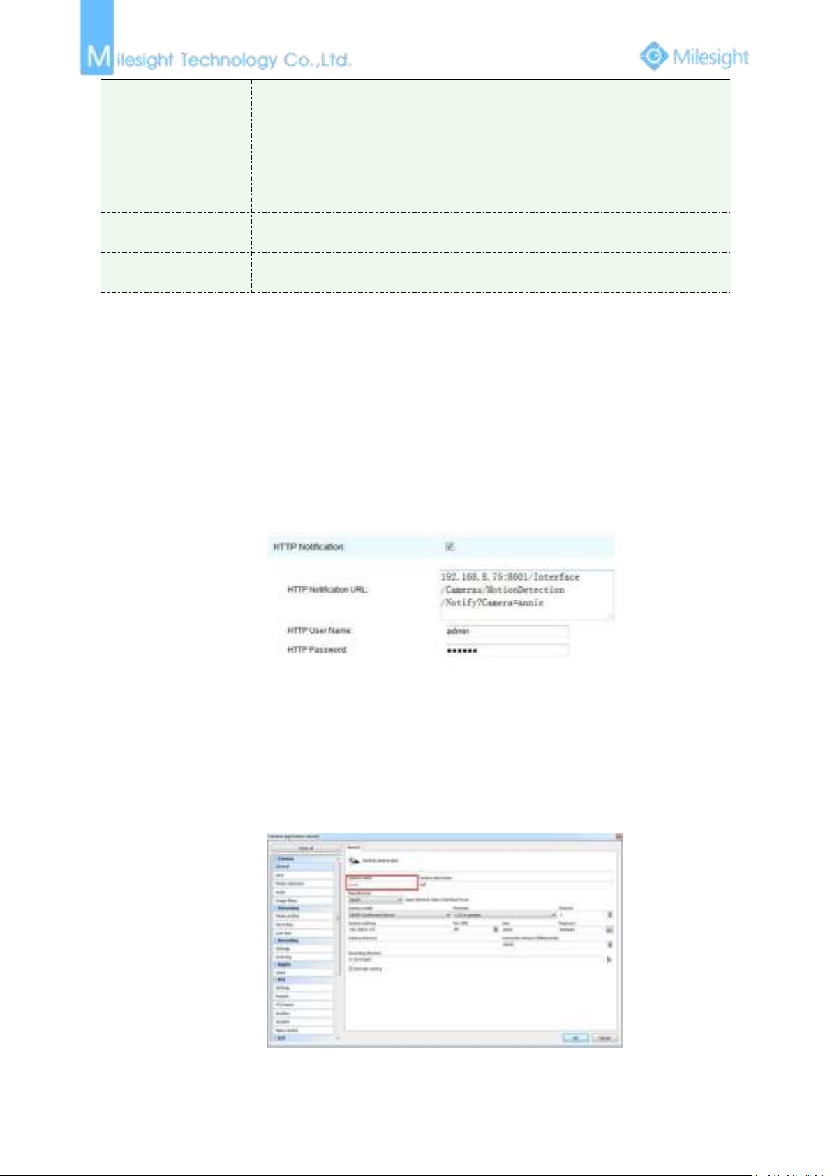
Step2: Check the HTTP Notification as Alarm Action, and fill the fields. Then save the alarm setting.
HTTP User Name: admin (the user name of your camera)
HTTP Password: ms1234 (the password of your camera)
HTTP Notification URL:
http://IP:8601/Interface/Cameras/MotionDetection/Notify?Camera=CameraName
IP refers to the PC's ip where the Digifort installed.
8601 is the port for Mothion signial in Digifort
CameraName is the camera name you set in Digifort VMS, like the picture shown below.
example:
http://192.168.8.75:8601/Interface/Cameras/MotionDetection/Notify?Camera=annie,
Page 69
63
this url format is exactly supported by Digifort VMS, so we can set as above to our cameras and get it
Parameters
Function Introduction
Record Video Sections
Six different periods are available(5, 10, 15, 20, 25, 30 sec)
Pre-record
Reserve the record time before alarm, 0~10 sec
Snapshot
The number of snapshot, 1~5
Snapshot Interval
This cannot be edited unless you choose more than 1 to Snapshot
Trigger Duration
Length of time an alarm lasts, this cannot be edited unless when you enable
the External Output on the Alarm Action firstly.
work well.
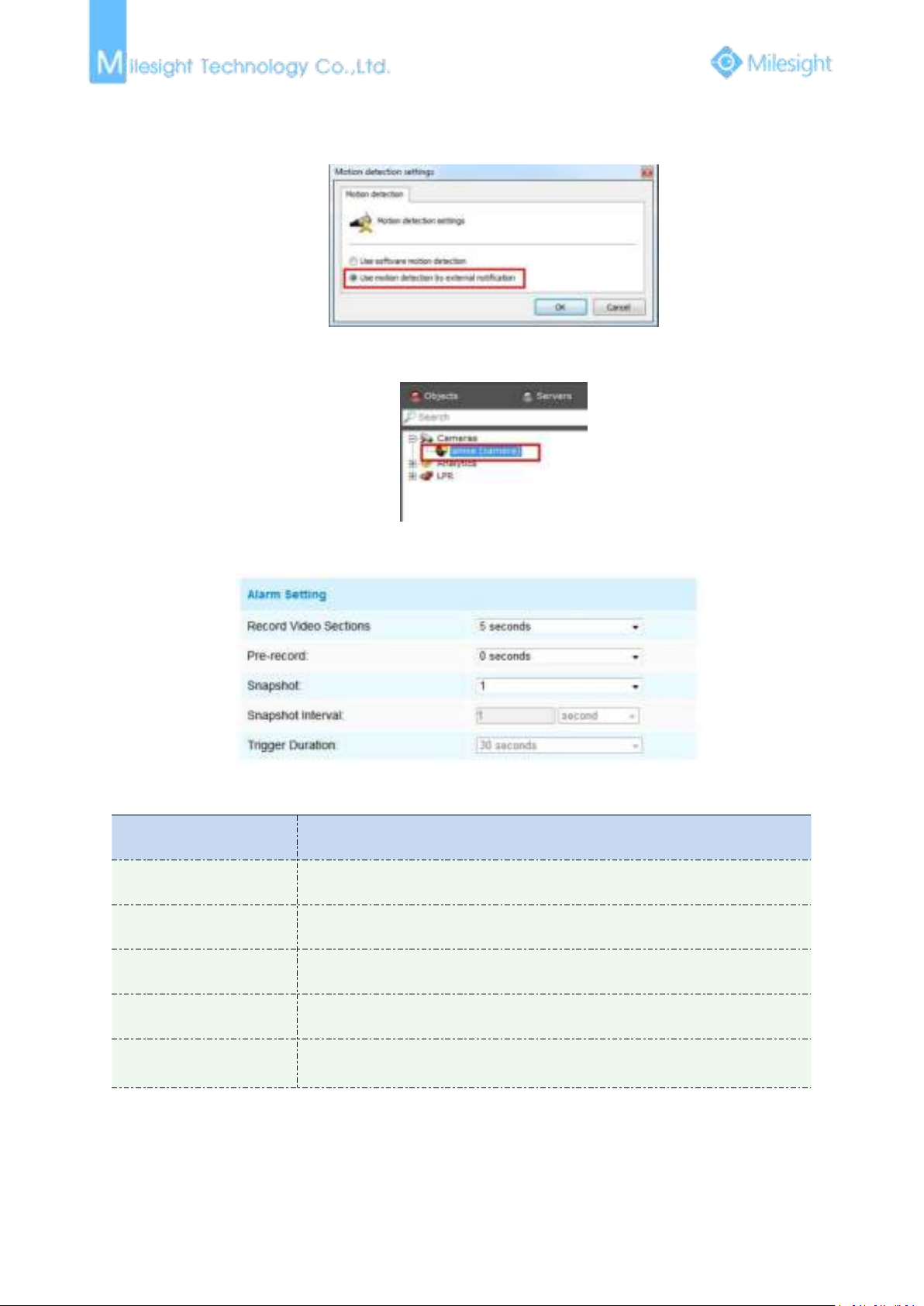
Step3: choose use motion detection by external notification.
Step4: If successfully, you can see the device icon turns yellow in the Surveillance when the camera is
under Motion Detection Alarm
So, it's the VMS Software which decides whether we can use this function successfully.
Step4: Set alarm settings.
Figure 4-4-13 Alarm Setting
Table 4-4-9 Description of the buttons
Audio Alarm
Enable the Audio before using Audio Alarm function.
Page 70
64
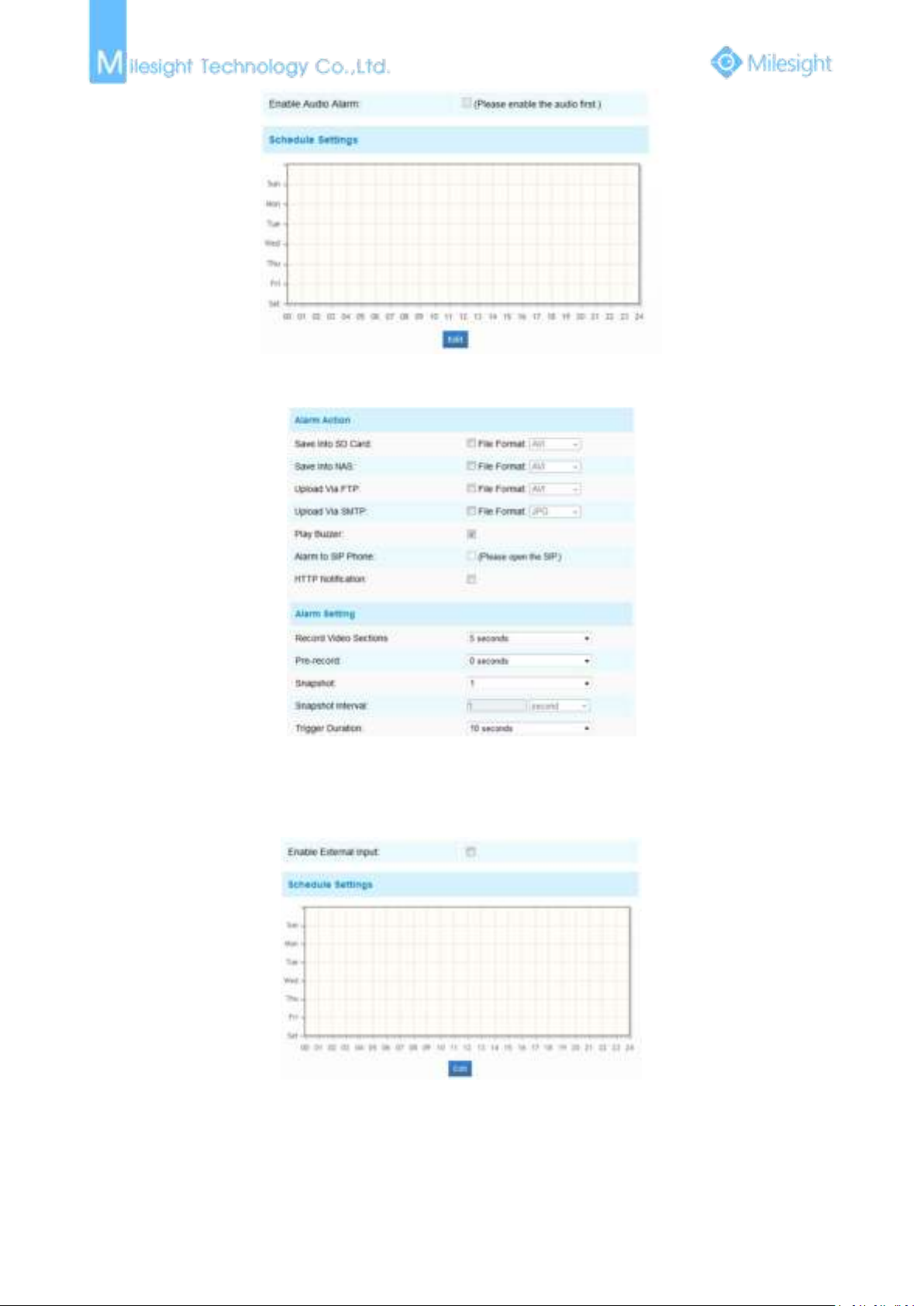
Figure 4-4-14 Schedule Settings
Figure 4-4-15 Alarm Setting
The meaning of items please refer to table 4-4-8 and 4-4-9, here will not repeat again.
External Input
Figure 4-4-16 Schedule Settings
Page 71
65
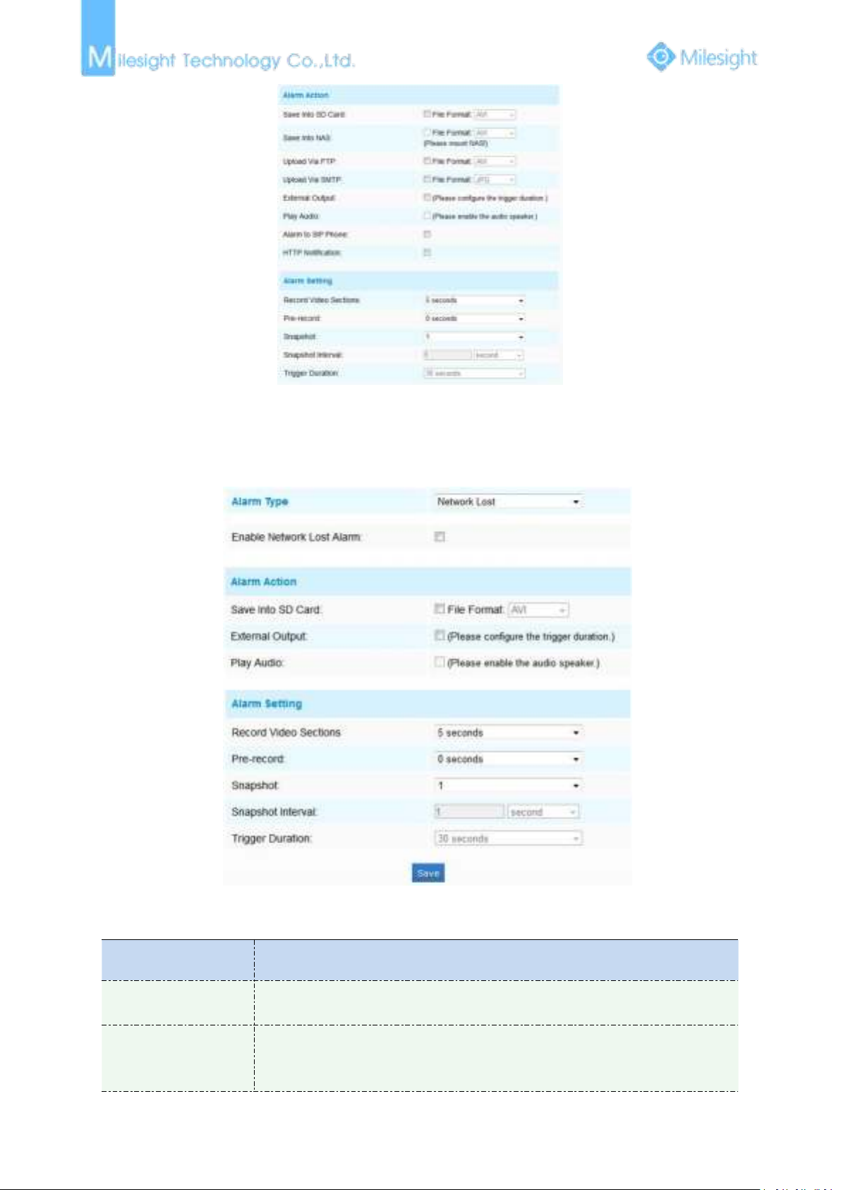
Figure 4-4-17 Alarm Setting
Parameters
Function Introduction
Alarm Type
Network Lost, Tampering and IP Address Conflicted are available
Check the checkbox to enable the alarm type you selected
Alarm Action
Save Into SD Card: Save alarm recording files into SD Card
External Output: If the camera equips with External Output, you can enable the
action after configuring the trigger duration
The meaning of items please refer to table 4-4-8 and 4-4-9, here will not repeat again.
Other Alarm
Figure 4-4-18 Other Alarm
Table 4-4-10 Description of the buttons
Page 72
66
Play Audio: If the camera equips with Speaker, you can enable the action after
configuring the audio speaker
Play Buzzer: If the camera equips with Buzzer, you can check the checkbox to
enable the function
Alarm Setting
Record Video Sections: Six different periods are available(5, 10, 15, 20, 25, 30
sec)
Pre-record: Reserve the record time before alarm, 0~10 sec
Snapshot: The number of snapshot, 1~5
Snapshot Interval: This cannot be edited unless you choose more than 1 to
Snapshot
Trigger Duration: Length of time an alarm lasts, this cannot be edited unless
when you enable the External Output on the Alarm Action firstly
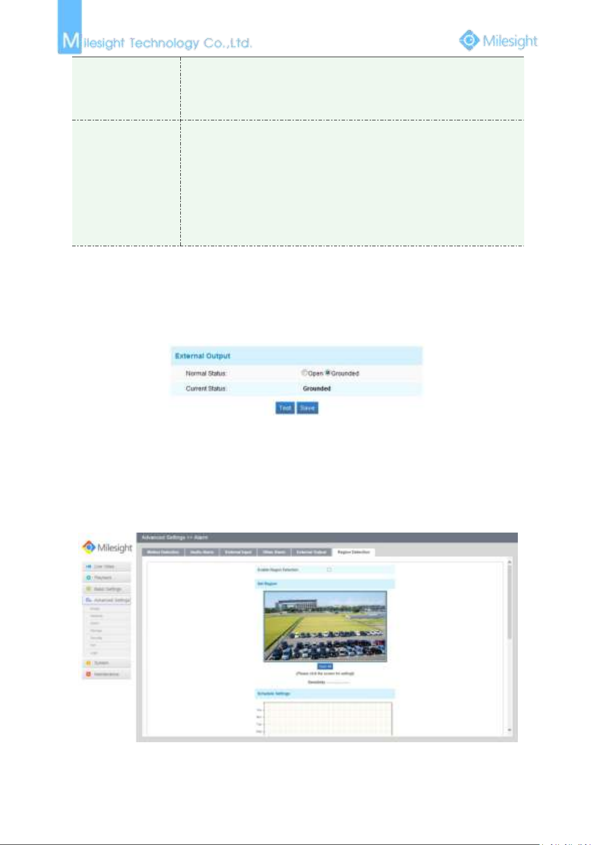
External Output
Figure 4-4-19 External Output Setting
Please set the Normal Status firstly, when the Current Status is different with Normal Status, it will lead to the
alarm.
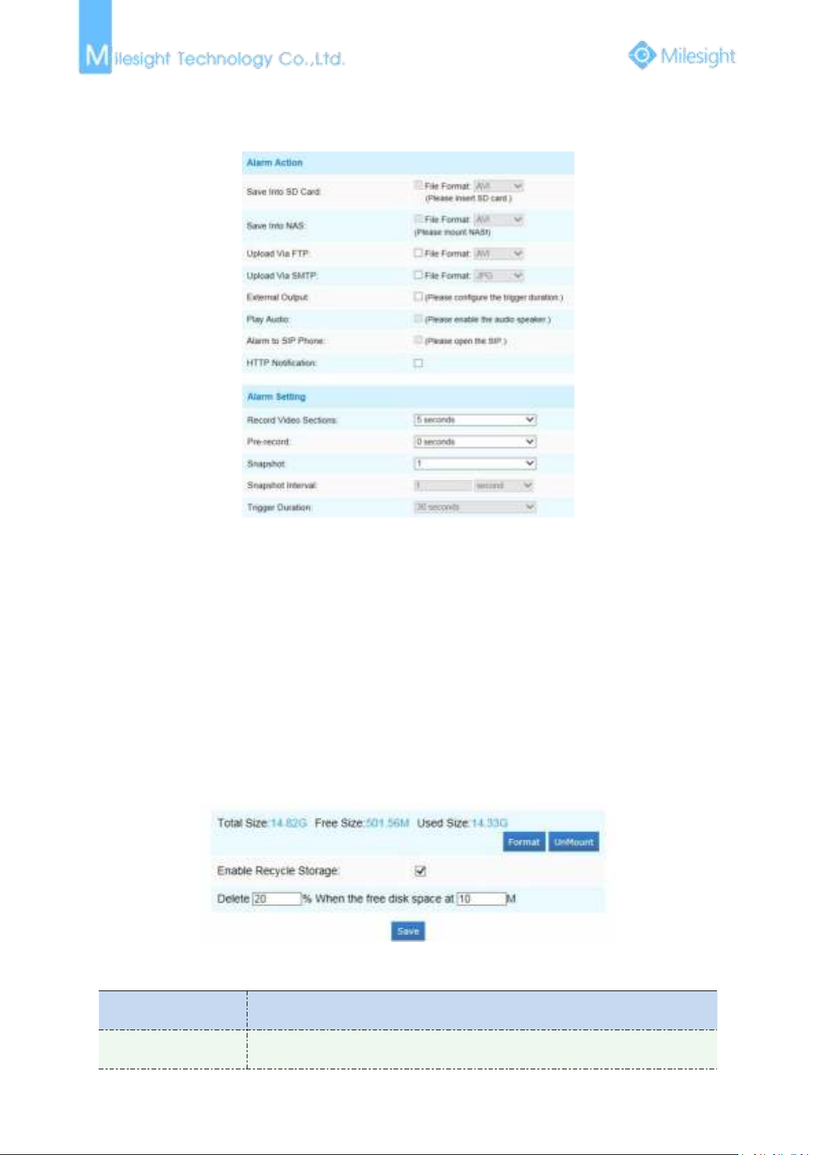
Region Detection
Region Detection is a target detection algorithm for H.265 series, it is a more exact motion
detection.
Step1: Set region, and
Figure 4-4-20 Region Detection Setting
Page 73
67
Step2: Set region detection schedule;
Parameters
Function Introduction
Format
Format SD card, the files in SD card will be removed
Step3: Set alarm action;
Step4: Set alarm settings.
Figure 4-4-21 Alarm Setting
The meaning of items please refer to table 4-4-8 and 4-4-9, here will not repeat again.
4.4.4 Storage
Before you start:
To configure record settings, please make sure that you have the network storage device within the
network or the SD card inserted in your camera.
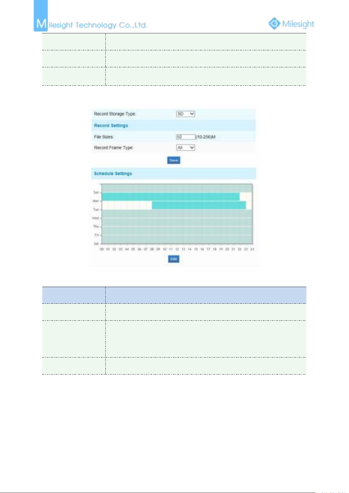
You can check “Enable cyclic storage”, then it will delete the files when the free disk space reach a
certain value. Choose the storage mode according to your needs.
SD Card
Figure 4-4-22 SD Card
Table 4-4-11 Description of the buttons
Page 74
68
Mount/UnMount
Mount/Dismount SD card
Enable cyclic storage
Enable/Disable cyclic storage
Delete
Enable cyclic storage, when the free disk space reach at a certain time, it will
automatically delete the files at certain percentage according to your settings
Record Schedule
Parameters
Function Introduction
Record Storage Type
SD or NAS are available
Record Settings
File Sizes: Set record file size, (10-256)M
Record Frame Type: All/Key
(All: Record all the frame
Key: Only record I-frame)
Schedule Settings
Click the Edit button to edit record schedule
Figure 4-4-23 Record Schedule
Table 4-4-12 Description of the buttons
NAS
The network disk should be available within the network and properly configured to store the
recorded files, etc.
NAS (Network-Attached Storage), connecting the storage devices to the existing network, provides
data and files services.
Page 75
69
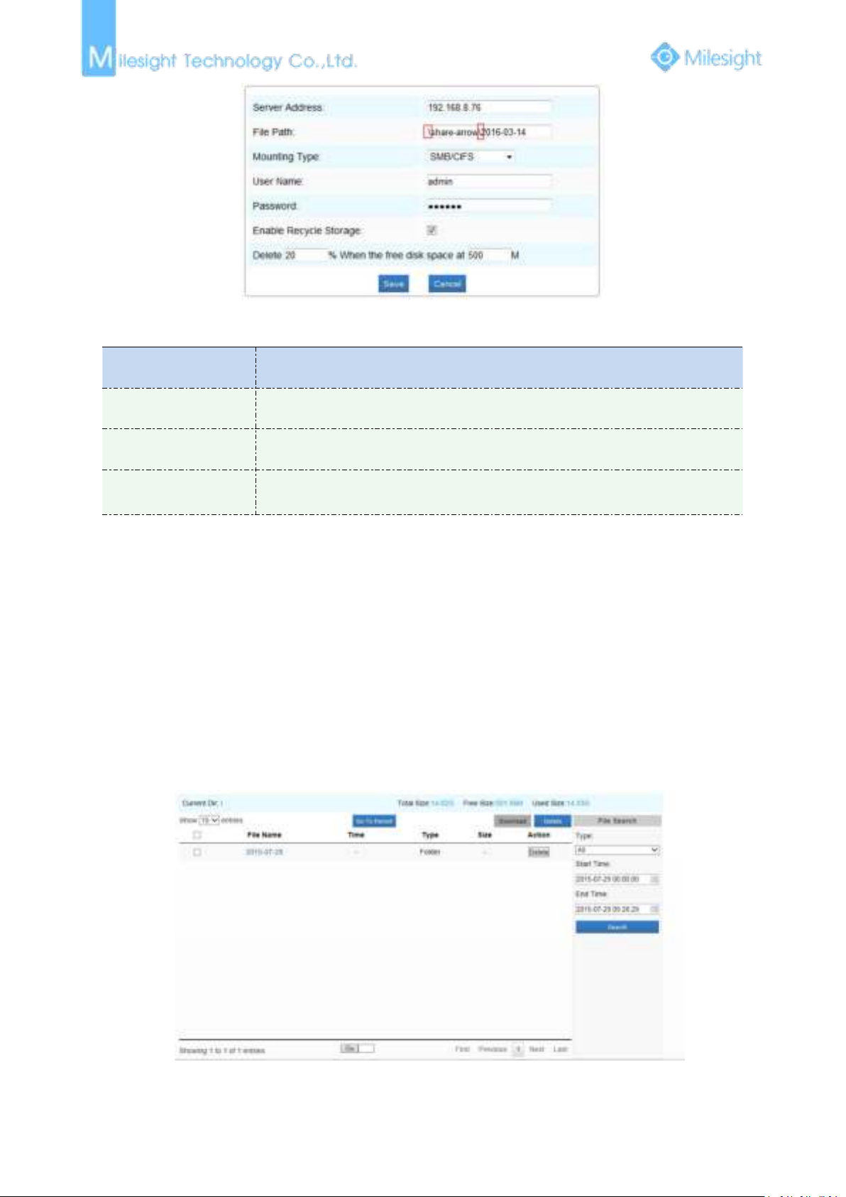
Figure 4-4-24 NAS
Parameters
Function Introduction
Server Address
IP address of NAS server
File Path
Input the NAS file path, e.g. “\path”.
Mounting Type
NFS and SMB/CIFS are available. And you can set the user name and password to
guarantee the security if SMB/CIFS is selected
1) Up to 5 NAS disks can be connected to the camera.
Table 4-4-13 Description of the buttons
Note:
SD Card Explorer
Files will be seen on this page when they are configured to save into SD card. You can configure
time schedules of video recording everyday and save video files to your desired location.
(
Note: Files are visible once SD card is inserted. Don’t insert or plug out SD card when power on.)
SD card video files are arranged by date. Each day files will be displayed under the corresponding
date, from here you can copy and delete files etc. You can visit the files in SD card by ftp, for
example,
camera account and the IP followed is the IP of your device.).
ftp://username:[email protected](user name and password are the same as the
Figure 4-4-25 SD Card Explore
Page 76
70
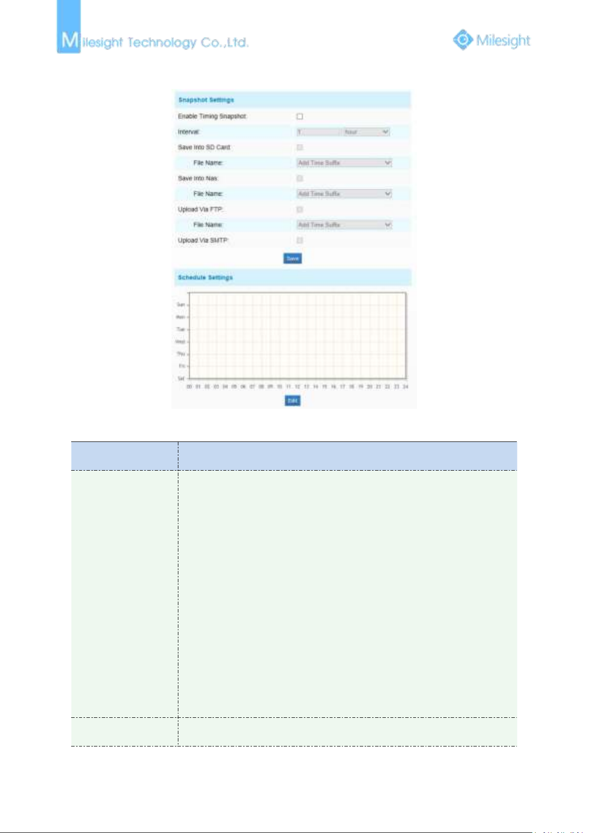
Snapshot
Parameters
Function Introduction
Snapshot Settings
Enable Time Snapshot: Check the checkbox to enable the Timing Snapshot
function
Interval: Set the snapshots interval, input the number and choose the
unit(millisecond, second, minute, hour, day)
Save Into SD Card: Save the snapshots into SD card, and choose the file name to
add time suffix or overwrite the base file name.
Save Into NAS: Save the snapshots into NAS, and choose the file name to add
time suffix or overwrite the base file name
Upload Via FTP: Upload the snapshots via FTP, and choose the file name to add
time suffix or overwrite the base file name
Upload Via SMTP: Upload the snapshots via SMTP
Please note:
There will be every snapshot picture if you choose to add time suffix, and only
latest picture when you choose the overwrite the base file name. When you
choose to add overwrite the base file name to SD, it will crate a file named
“Snapshot” to place the snapshot while the NAS and FTP wont.
Schedule Settings
Click the Edit button to edit record schedule
Figure 4-4-26 Snapshot
Table 4-4-14 Description of the buttons
Page 77
71
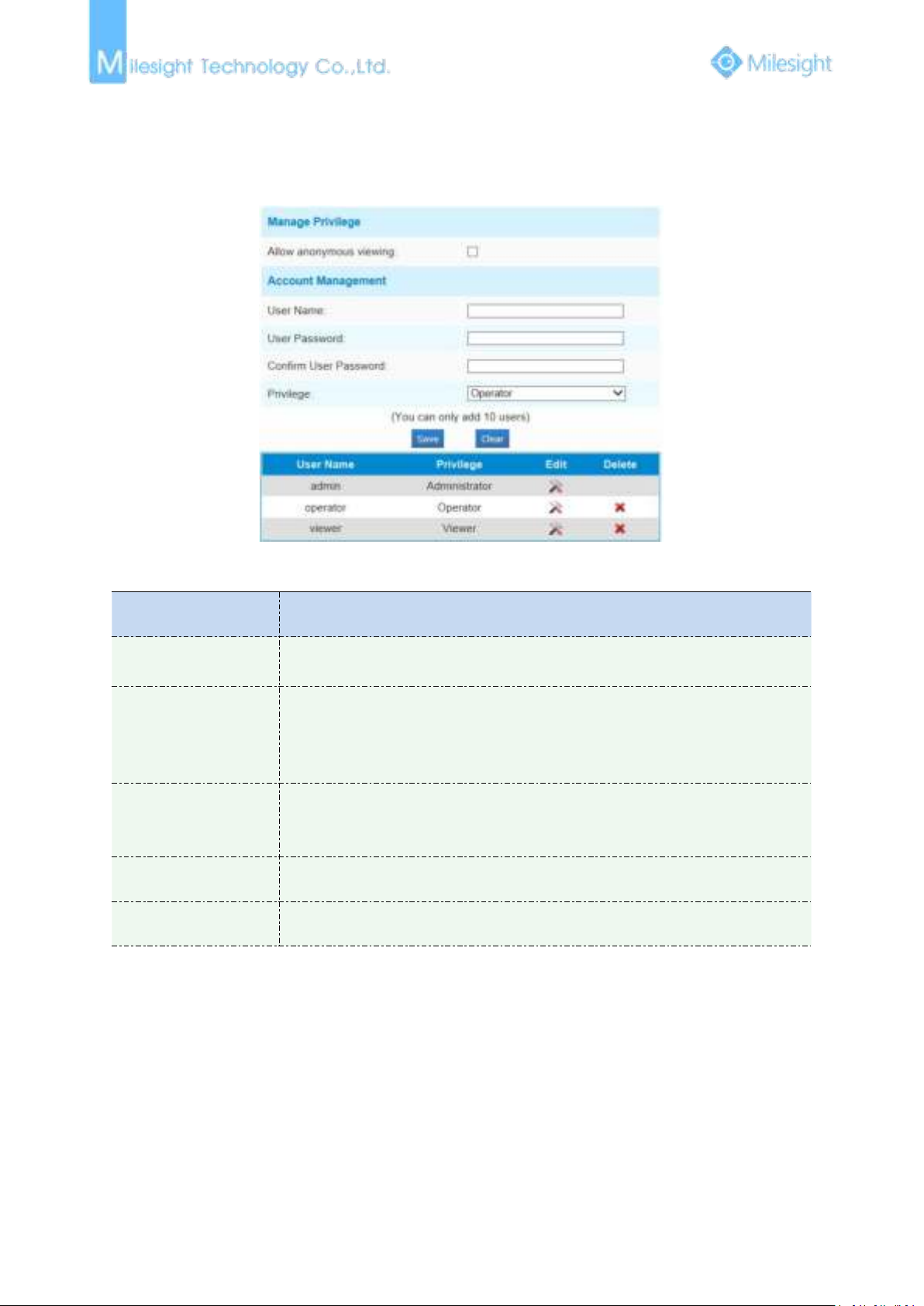
4.4.5 Security
Parameters
Function Introduction
Manage Privilege
Allow anonymous viewing: Check the checkbox to enable visit from whom
doesn’t have account of the device
Account Management
User Name: Input user name for creating an account
User Password: Input password for the account
Confirm User Password: Confirm the password
Privilege: Set the privilege for the account
Administrator
An administrator can manage all configuration pages of the device, including
change user password, add or delete users (the default user “admin” cannot be
deleted)
Operator
An operator can manage all configuration pages except the User page
Viewer
A viewer can`t change any settings
User
Figure 4-4-27 User
Table 4-4-15 Description of the buttons
Anonymous Visit
Set the Anonymous visit permission Enable or Disable in the drop-down list to enable or disable
the anonymous visit. There will be a checkbox of Anonymous next time you logging in.
Page 78
72
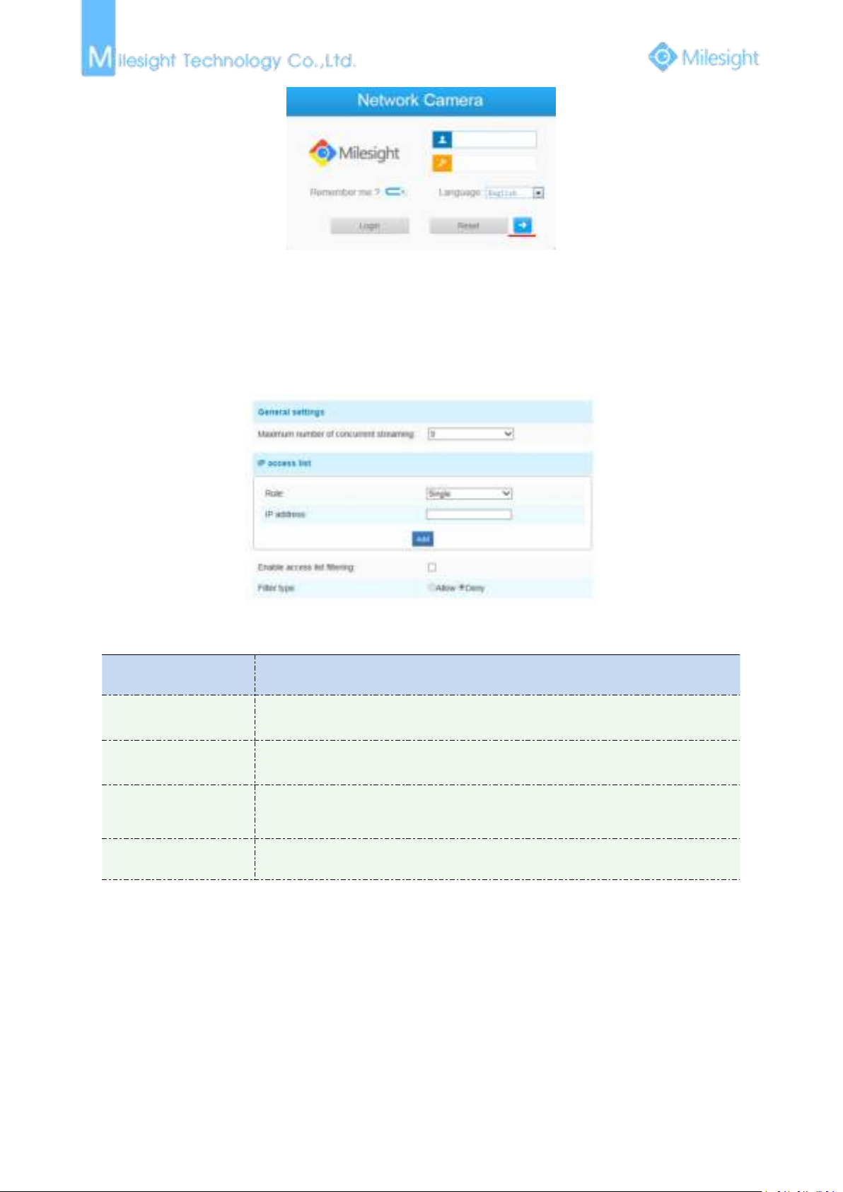
Click Anonymity and log in.
1) Only live view is available for the anonymous user.
Parameters
Function Introduction
General Settings
Maximum number of concurrent streaming: Select the maximum number of
concurrent streaming. Options include No Limit, 1~9
IP access list
Rule: Single, Network and Range are available
IP address: Input the address to get the access to the device
Enable access list
filtering
Able to access or restrict access for some IP address
Filter type
Access or restrict access
Note:
Access List
Figure 4-4-28 Log in interface
Figure 4-4-29 Access List
Table 4-4-16 Description of the buttons
4.4.6 SIP
The Session Initiation Protocol(SIP) is a signaling communications protocol, widely used for
controlling multimedia communication sessions such as voice and video calls over Internet
Protocol(IP) networks. This page allows user to configure SIP related parameters. Milesight
cameras can be configured as SIP endpoint to call out when alarm triggered; or allow permitted
number to call in to check the video if the video IP phone is used. To use this function, the settings
in SIP page must be configured properly. SIP can be achieved in two ways to get the video, one is to
Page 79
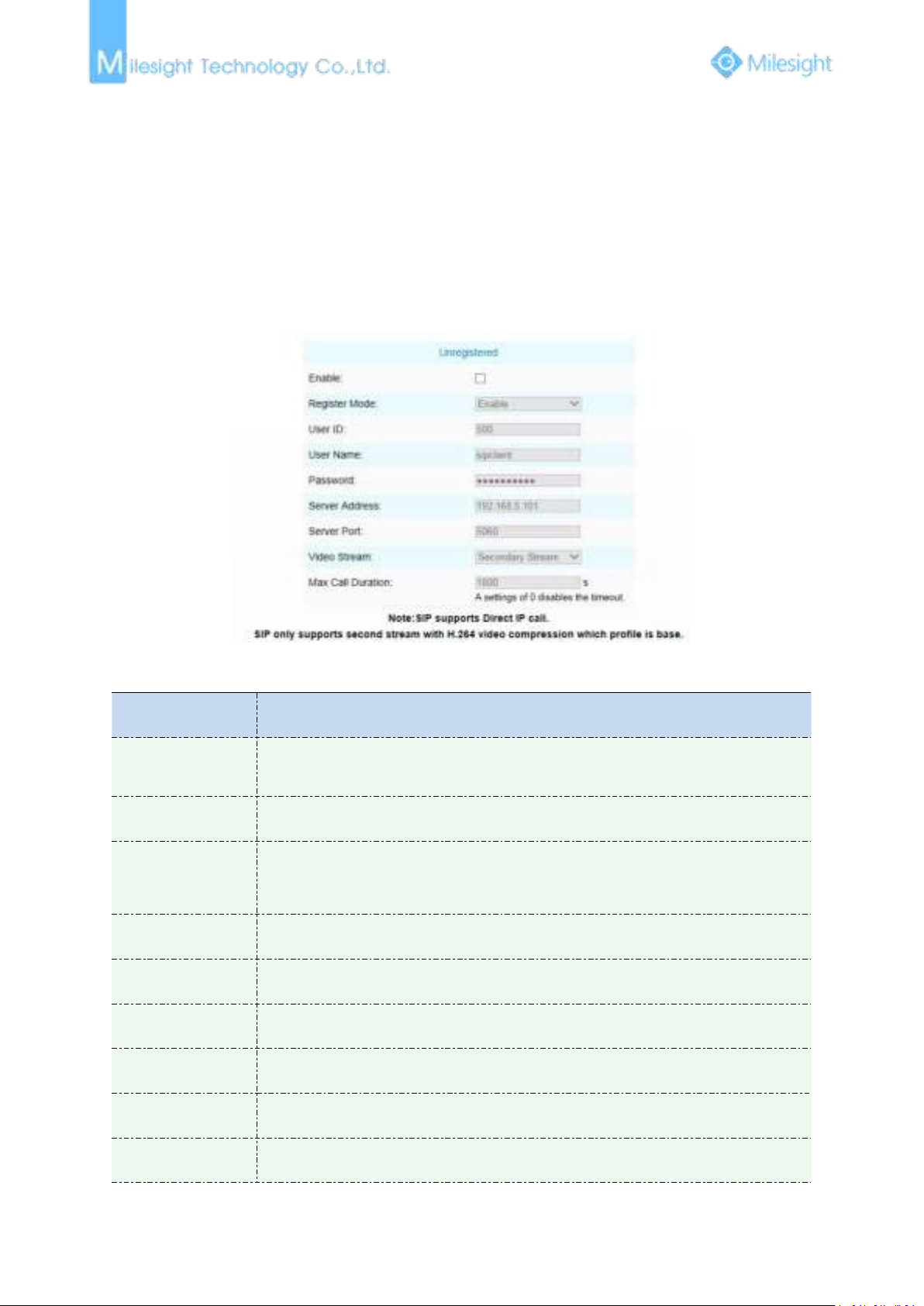
73
dial the IP address directly, the other is account registration mode, the details are as follows:
1) Before using the SIP, you need to register an account for the camera from the SIP server;
2) Register another user account for the SIP device from the same SIP server;
3) Call the camera User ID from the SIP device, you will get the video on the SIP device.
Parameters
Function Introduction
Unregistered/
Registered
SIP registration status. Display “Unregistered” or “Registered”
Enable
Start or stop using SIP
Register Mode
Choose to use Enable mode or Disable mode. Enable mode means to use SIP with
register account. Disable mode refers to use SIP without register account, just use the
IP address to call.
User ID
SIP ID
User Name
SIP account name
Password
SIP account password
Server Address
Sever IP address
Server Port
Sever port
Video Stream
Choose the video stream
Method 1: IP Direct mode
Dial on the camera’s IP address directly through SIP phone, so you can see the video
(
Note: SIP phone and the camera should in the same network segment).
Method2: Account registration mode
SIP Settings
Figure 4-4-30 SIP
Table 4-4-17 Description of the buttons
Page 80
74
Max Call Duration
The max call duration when use SIP
Note:
1) SIP supports Directly IP call;
2) SIP only supports second stream with H.265/H.264 or MPEG4 Video Compression.
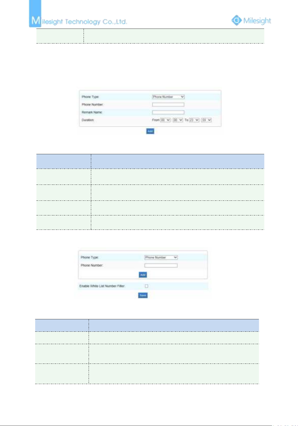
Alarm Phone List
Figure 4-4-31 Alarm Phone List
Table 4-4-18 Description of the buttons
Parameters
Function Introduction
Phone Type
Phone Number(Call by phone number) & Direct IP Call(Check to accept peer to
peer IP call).
Phone Number/
IP Address
Call by phone number or IP address.
Remark Name
Display name.
Duration
The time schedule to use SIP.
Figure 4-4-32 White List
Table 4-4-19 Description of the buttons
Parameters
Function Introduction
Phone Type
Phone Number(Call by phone number) & Direct IP Call
Phone Number/
IP Address
Including the phone number or IP address on the whitelist
Enable White List
Number Filter
When enabled, only the designated phone number or IP address can visit
White List
Page 81
75
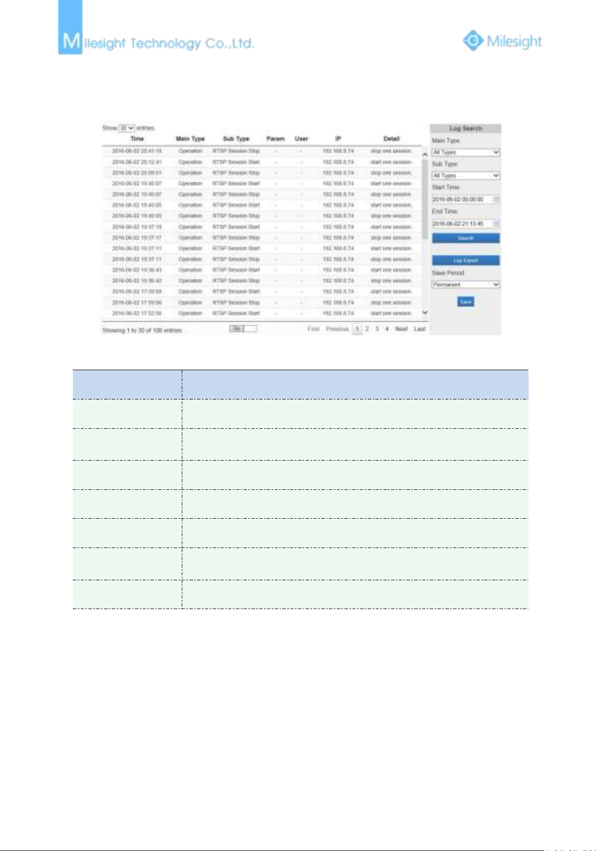
4.4.7 Logs
Parameters
Function Introduction
Main Type
There are five main log types: All Type, Event, Operation, Information, Exception
Sub Type
On the premise of main type has been selected, select the sub type to narrow the
range of logs
Start Time
The time log starts
End Time
The time log ends
Log Export
Export the logs
Save Period
Set the period of log saving, there are eight options to choose: Permanent and
30/60/120/180/240/300/360 Days
Go
Input the number of logs’ page
The logs contain the information about the time and IP that has accessed the camera through web.
Figure 4-4-33 Logs
Table 4-4-20 Description of the buttons
4.5 System
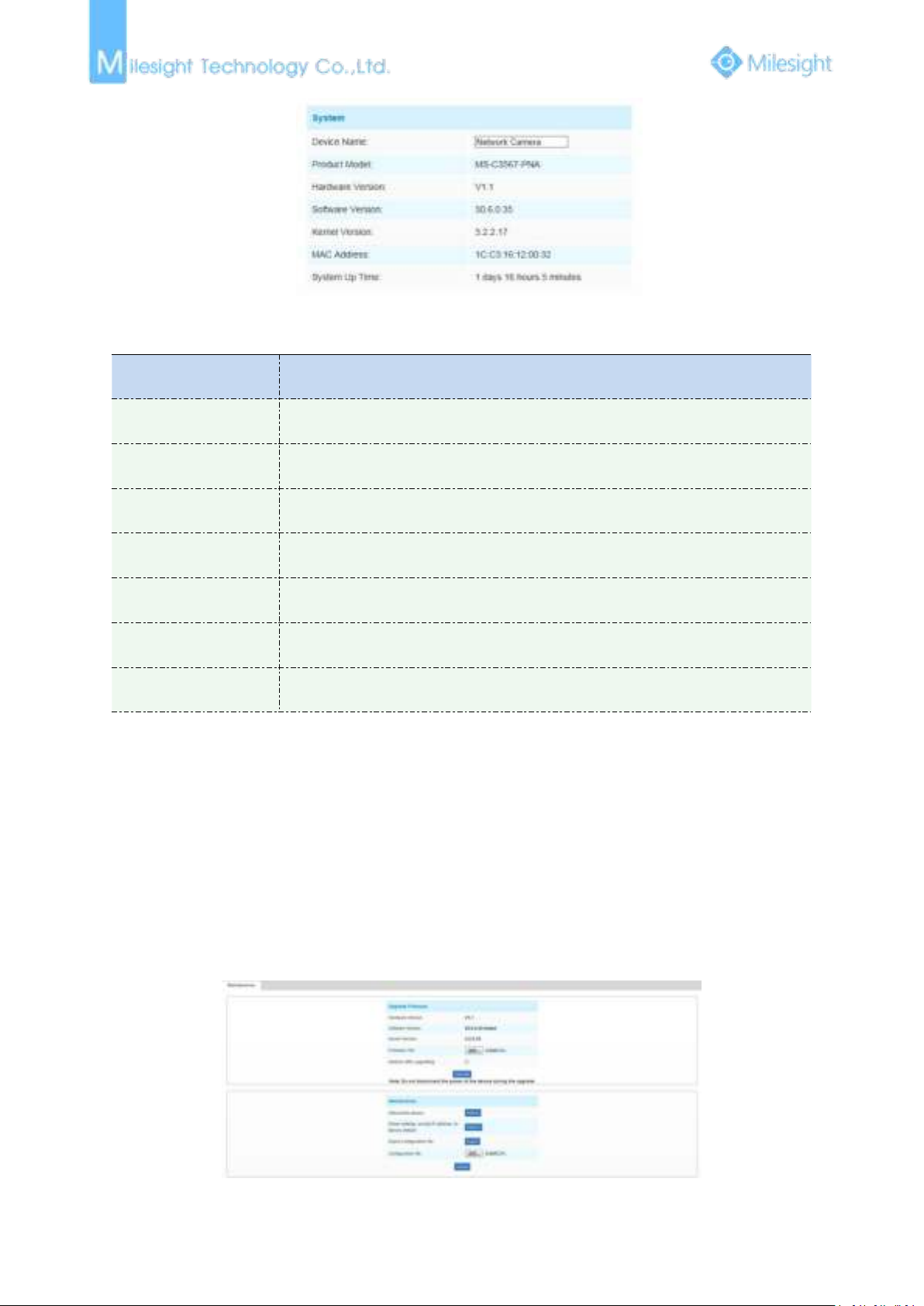
All information about the hardware and software of the camera can be checked on this page.
Page 82
76
Parameters
Function Introduction
Device Name
The device name can be customized. It will be seen in file names of video files
Product Model
The product model of the camera
Hardware Version
The hardware version of the camera
Software Version
The software version of the camera can be upgraded
Kernel Version
The kernel version
MAC Address
Media Access Control address
System Up Time Since
The elapsed time since the last restarted of the device
4.6 Maintenance
1) Do not disconnect the power of the device during the update. The device will be restarted to
Figure 4-5-1 System
Table 4-5-2 Description of the buttons
The software can be upgraded by the following steps:
Step1: Browse and select the upgrading file;
Step2: Click the “upgrade” button after it prompts upload file successfully. After the system
reboots successfully, the update is done.
Note:
complete the upgrading.
Figure 4-5-2 Maintenance
Page 83
77
Table 4-5-3 Description of the buttons
Parameters
Function Introduction
Upgrade Firmware
Hardware Version: The hardware version of the camera
Software Version: The software version of the camera
Kernel Version: The kernel version
Firmware File: Select the firmware used to upgrade
Maintenance
Reboot the device: Click “Reboot” button to restart the device immediately
Restore settings, except IP address to Factory Default: Click “Restore” button to
restore the camera to factory default settings
Export configuration file: Click this button to export the configuration file
Configuration file: Click this button to import the old configuration file
Page 84

78
Chapter V Services
Milesight Technology Co., Ltd provides customers with timely and comprehensive technical
support services. End-users can contact your local dealer to obtain technical support. Distributors
and resellers can contact directly with Milesight for technical support.
Technical Support Mailbox: [email protected]
http://www.milesight.com
Web:
Online Problem Submission System: http://www.milesight.com/service/feedback.asp
Address: No.23 Wanghai Road,2nd Software Park, Xiamen, China
Zip Code: 361006
TEL: +86-592-5922772
FAX: +86-592-5922775
Milesight
More in Sight
 Loading...